

Page 1
THE INDUSTRIAL NETWORK COMPANY
The
N-TRON
®
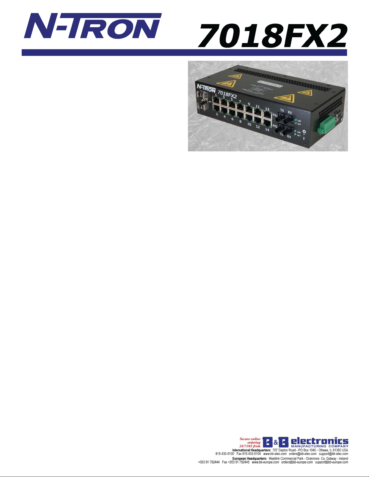
7018FX2 gigabit capable Industrial Ethernet Switch
offers outstanding performance and ease of use. It is ideally suited
for connecting Ethernet enabled industrial and/or security equipment
and is a fully managed switch.
PRODUCT FEATURES
• Fourteen 10/100BaseTX RJ-45 Ports
• Two 100BaseFX Ports, ST or SC Style
• Two Optional SFP (Mini-GBIC) Gigabit Transceivers
• 1000BaseSX/LX Fiber with LC style connectors or
• 1000BaseT Copper with RJ-45 connectors
• -40
o
C to 70oC Operating temperature
• ESD and Surge Protection Diodes on all Ports
• Auto Sensing 10/100BaseTX, Duplex, and MDIX
• Redundant Power Inputs (10-30VDC)
• High Voltage Option (40-160VDC)
• Confi gurable Alarm Contact & Bi-Color Fault Status LED
Fully Managed Features:
• SNMP v1, v2, v3 and Web Browser Management
• Detailed Ring Map and Fault Location Charting
• N-Ring
• N-View
• N-Link
• Plug-and-play IGMP Support
• 802.1Q tag VLAN and Port VLAN
• 802.1p QoS and Port QoS
• EtherNet/IP™ CIP Messaging
• LLDP (Link Layer Discovery Protocol)
• Port Trunking
• Port Mirroring
• 802.1d, 802.1w, 802.1D RSTP
• DHCP Server, Option 82 relay, Option 61
Management Features
The
7018FX2
confi gured using a web browser.
IGMP Snooping - Internet Group Management Protocol allows the
7018FX2
VLAN - V irtual Local Area Network allows you to segment the switch
in order to create two or more separate local area network domains.
QoS - Quality of Service provides prioritization of network traffi c in
order to provide better network service. QoS improves the latency of
prioritized Ethernet packets required for ring management, real-time,
and other interactive applications.
Port T runking - Trunking (link aggregation) enables multiple physical
ports to be linked together and function as one uplink to another
N-TRON
thereby increasing the bandwidth between switches. This confi guration
can provide increased bandwidth and redundancy to applications
requiring high levels of fault tolerant operation.
Port Mirroring - Allows the traffi c on one port to be duplicated and sent
to a designated mirror port. Port mirroring is used to monitor Ethernet
traffi c on the designated source port using the assigned mirror port.
DHCP-DHCP Server / Client automates the assignment of IP addresses.
DHCP Option 82 assures that if a device on a specifi c port is replaced,
the replacement receives the same IP address as the original device.
™
Technology with ~30ms Healing
™
OPC Monitoring
™
Redundant N-Ring Coupling
offers several management functions that can be easily
switch to forward and fi lter multicast traffi c intelligently.
trunking capable switch confi gured in the same manner,
Shown with Optional Gigabit
SFP Transceivers installed
Rapid Spanning Tree Protocol
RSTP allows the switch to be confi gured in a ring or mesh topology,
and provides support for redundant path communications with high
speed (rapid) healing.
Remote Monitoring Options
For ease of confi guration and monitoring, the
browser management and
server software. The
N-TRON
N-VIEW
OLE for process control (OPC)
N-VIEW
software can be combined
7018FX2
offers web
with popular HMI software packages to add network traffi c monitoring,
trending, and alarming to any application using
N-TRON
switches In
addition, SNMP is available for switch link and status monitoring. The
alarm contact and status LED can be confi gured to respond to power
N-Ring
failure on power input 1 or input 2,
broken, partial break high,
partial break low, or if multiple ring managers are detected.
N-Ring T echnology
N-TRON's 7018FX2
ring manager using
N-TRON's N-Ring
technology offers expanded ring size capacity, detailed fault
diagnostics, and a standard healing time of ~30ms. The
7018FX2
ring manager periodically checks the health of the ring via
packets. If the ring manager stops receiving these health check
packets, it converts the ring to a linear topology within ~30ms.
switches in the ring are
N-TRON
fully managed switches, a detailed
When all
ring map and fault location chart will also be provided on the ring
manager’s web browser and OPC server to identfy the health status of the
ring.
N-Link™
managed
allows the linking of two
N-TRON
switches can participate in
N-Rings
. Up to 250 fully
N-Ring
topologies.
Industrial Packaging and Specifi cations
The
7018FX2
is designed to operate in industrial environments. It is
housed in a rugged steel DIN-Rail enclosure. It has extended industrial
specifi cations and features to meet or exceed the operating parameters
of connected equipment. These include extended temperature ratings,
extended shock and vibration specs, redundant power inputs, and high
MTBF (greater than 2M hours).
Ease of Use
The 10/100BaseTX ports are auto sensing and auto confi guring. Each
copper port is automatically negotiated for maximum speed and
performance by default, but can also be hard coded through the user
interface. The two optional gigabit ports support full 2000 Mb/s
communications via 1000BaseSX/LX/T. For added fl exibility, these
SFP (Mini-GBIC) gigabit transceivers are fi eld upgradable or can be
factory installed at the time of purchase.
Page 2
THE INDUSTRIAL NETWORK COMPANY
7018FX2 Industrial Ethernet Switch Ordering Information
7018FX2-XX Fourteen 10/100BaseTX Ports, Two Multimode 100BaseFX Fiber Optic Ports, Two Optional Gigabit SFP Ports
7018FXE2-XX-YY Fourteen 10/100BaseTX Ports, Two Singlemode 100BaseFX Fiber Optic Ports, Two Optional Gigabit SFP Ports
NTSFP-TX Optional SFP (Mini-GBIC) Transceiver with One 1000BaseT GB Copper Port
NTSFP-SX Optional SFP (Mini-GBIC) Transceiver with One 1000BaseSX Multimode GB Fiber Optic Port
NTSFP-LX-ZZ Optional SFP (Mini-GBIC) Transceiver with One 1000BaseLX Singlemode GB Fiber Optic Port
700-PM Panel Mount kit
URMK Universal Rack Mount Kit
Where: XX = ST or SC, YY = 15, 40, or 80 for Singlemode, Blank for Multimode
E = Singlemode, and Blank Otherwise
ZZ = 10, 40, or 70 for GB Singlemode
If SFP Transceiver is not specifi ed at the time of purchase, slots will remain blank with covers
7018FX2 Specifi cations
Switch Properties
Number of MAC Addresses: 8000
Aging Time: Programmable
Latency Typical: 2.6 s
Switching Method : Store-and-Forward
Case Dimensions
Height: 2.3" (5.8 cm)
Width: 8.3" (21.0 cm)
Depth: 4.8" (12.1 cm)
Weight (max): 3.3 lbs (1.5 kg)
DIN-Rail Mount: 35mm
Electrical
Redundant Input Voltage: 10-30 VDC (Regulated)
Input Current (max): 520mA max. @24V
N-TRON Power Supply: NTPS-24-1.3 (1.3 A@24V)
Environmental
Operating Temperature: -40oC to 70oC
Storage Temperature: -40oC to 85oC
Operating Humidity: 5% to 95%
(Non Condensing)
Operating Altitude: 0 to 10,000 ft.
Shock and Vibration (bulkhead mounted)
Shock: 200g @ 10ms
Vibration/Seismic: 50g, 5-200Hz, Triaxial
Reliability
MTBF: >2 Million Hours
Network Media
10BaseT: >Cat3 Cable
100BaseTX: >Cat5 Cable
1000BaseT: >Cat5e Cable
100BaseFX, 1000BaseSX
Multimode: 50-62.5/125m
100BaseFXE, 1000BaseLX
Singlemode: 7-10/125m
100 Mb Fiber Transceiver Characteristics
Fiber Length 2km* 15km** 40km** 80km**
TX Power Min -19dBm/-14dBm -15dBm/-7dBm -5dBm/0dBm -5dBm/0dBm
RX Sensitivity Max -32dBm -34dBm -34dBm -34dBm
Wavelength 1310nm 1310nm 1310nm 1550nm
* Multimode Fiber Optic Cable
** Singlemode Fiber Optic Cable
SFP Gigabit Fiber Transceiver Characteristics
Fiber Length 550m for 50/125μm 10km** 40km** 70km**
TX Power Min -9.5dBm/-4dBm -9.5dBm/-3.5dBm -2dBm/3dBm 0dBm/5dBm
RX Sensitivity Max -17dBm -20dBm -22dBm
Wavelength 850nm 1310nm 1310nm 1550nm
Assumed Fiber Loss .45dB/km .35dB/km .25dB/km
Laser Type VCSEL FP DFB DFB
Connectors
* SX Fiber Optic Cable
** LX Fiber Optic Cable
-23dBm
10/100BaseTX: Fourteen (14) RJ-45 Copper Ports
100BaseFX: Two (2) SC or ST Fiber Duplex Ports
1000BaseT: Up to Two (2) RJ-45 Gigabit
Copper Ports (optional)
1000BaseSX: Up to Two (2) LC Duplex Gigabit
Fiber Ports (optional)
Recommended Wiring Clearance
Front: 4" (10.16 cm)
Side: 1" (2.54 cm)
Regulatory Approvals
FCC Title 47, Part 15, Subpart B - Class A; ICES-003 - Class A
UL Listed (US and Canada) 1604; ANSI/ISA-12.12.01-2007
Class I, Div 2, Groups A, B, C, D, and T4A
CE: EN61000-6-2:2001: EN61000-4-2, 3, 4, 5, 6
EN55022:1998+A1:1999+A2:2002-Class A
EN50155 for Railway Applications
GOST-R Certifi ed, RoHS Compliant
Designed to comply with:
IEEE 1613 for Electric Utility Substations
NEMA TS1/ TS2 for Traffi c control
Contact Information
N-TRON Corp. N-TRON Europe GmbH
820 S. University Blvd., Suite 4E Alte Steinhauserstr 19
Mobile, AL 36609 USA 6330 Cham / Zg Switzerland
TEL: (251) 342-2164 TEL: +41 41 7406636
FAX: (251) 342-6353 FAX: +41 41 7406637
Website: www.n-tron.com
Email: N-TRON_info@n-tron.com
REV 090805
® 2009
N-TRON
, Corp.
N-TRON
and the
N-TRON
may be trademarks and/or registered trademarks of their respective company. Specifi cations subject to change without notice. The responsibility for the use and application
N-TRON
of
shall not be liable for any damage resulting from the installation, use, or misuse of this product.
products rests with the end user.
N-TRON
logo are trademarks of
makes no warranties as to the fi tness or suitability of any
N-TRON
, Corp. Product names mentioned herein are for identifi cation purposes only and
N-TRON
Printed in USA.
product for any specifi c application.
N-TRON
Corporation
Page 3

THE INDUSTRIAL NETWORK COMPANY
7018FX2 Drawings on N-TRON Tech Docs Page
® 2009
N-TRON
, Corp.
N-TRON
and the
N-TRON
logo are trademarks of
N-TRON
, Corp. Specifi cations subject to change without notice. Printed in USA.
 Loading...