

Page 1
4WSD9TB-0712 - p1/5
www.bb-elec.com orders@bb-elec.com support@bb-elec.com
International Office: 707 Dayton Road PO Box 1040 Ottawa, IL 61350 USA 815-433-5100 Fax 433-5104
European Office: Westlink Commercial Park Oranmore Co. Galway Ireland +353 91 792444 Fax +353 91 792445
PRODUCT INFORMATION B&B ELECTRONICS
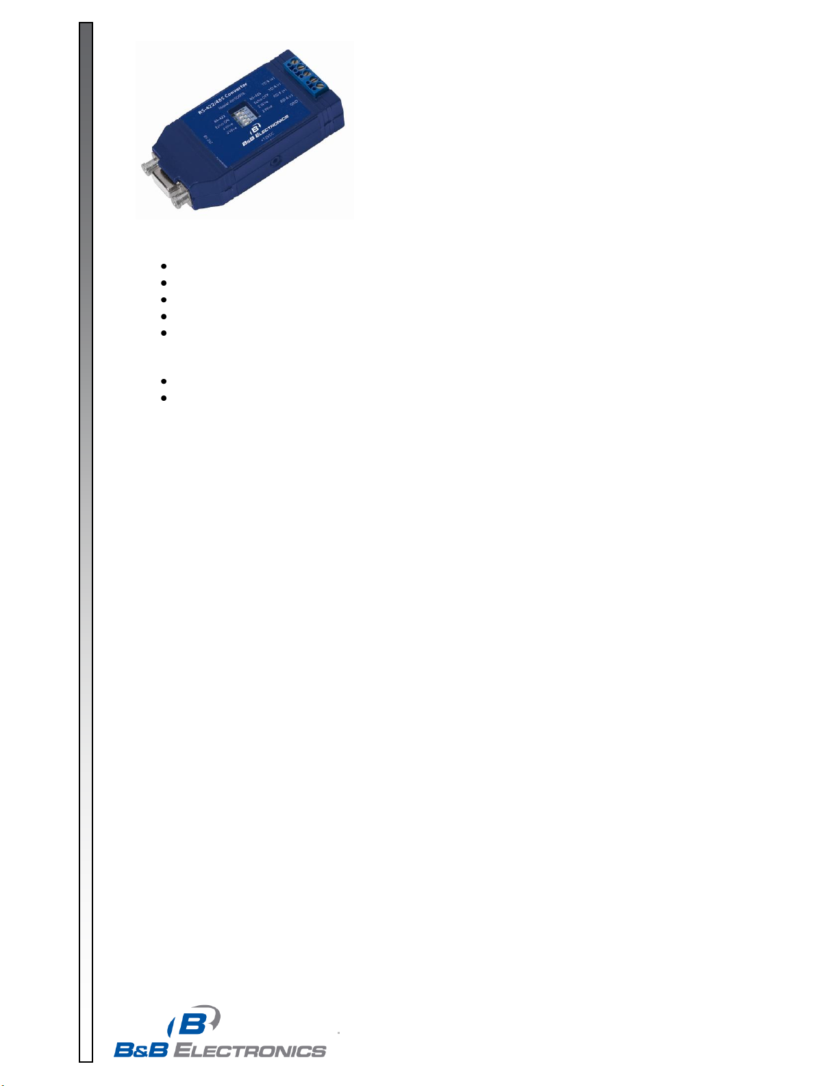
Model: 4WSD9TB
Universal Converter
Covers All the Bases:
RS-232 to 4-wire RS-422, 2-wire or 4-wire RS-485
Highlights
Selectable RS-485 2-wire half-duplex, or RS-485 4-wire full-duplex operation
Selectable RS-422 operation - Transmit & Receive always enabled
DB9 Female RS-232 Connection, Terminal Blocks for RS-422/RS-485
Port power or External 12V DC power (jack)
Automatic RS-485 Driver Control - works without special programming
o Enables Transmitter from RS-232 TD signal
o Enables Receiver when not Transmitting (half duplex)
Built-in bridging switches for 2-wire or 4-wire modes – no external jumpers
Operating Mode Switches: 4
o Transmit mode, Receive Mode, and 2 switches for 4-Wire or 2-Wire
o Receiver mode: Echo On (4-wire) or Echo Off (2-wire RS-485)
o Two 4-wire/2-wire switches for full or half duplex (bridge) connections
Description
The 4WSD9TB Universal Converter provides RS-232 to RS-422/RS-485 conversion using either port-power or an
external power supply. Data is converted in both directions, RS-232 Transmit data is converted to balanced RS422 or RS-485 Transmit, and Received RS-422/RS-485 signals are converted to RS-232. Unlike converters
which require programming hardware handshaking signals to control RS-485 or RS-422 operation, the 4WSD9TB
provides automatic control. In RS-485 mode, the RS-485 driver is enabled by circuitry which senses the RS-232
TD input. In half duplex RS-485 mode, the receiver is enabled when not transmitting. For full duplex operation,
the receiver is set always enabled. In RS-422 mode, the transmitter and receiver are always enabled. The
operating mode is set with 4 switches (Table 1). The 4WSD9TB is powered by the RS-232 signal lines whether
they are set high or low. If not enough power is available from the port, or no handshaking lines are available, a
DC jack is provided to connect a 12VDC supply. The DB9 female connector for RS-232 is wired as DCE (like a
modem).
Power
No external power is required if two RS-232 output handshake lines (RTS & DTR) are available and the
cable run is short. If the handshake lines are raised (enabled) and no termination is used, the power
efficiency is greatly increased. Less than 3mA is required to operate the 4WSD9TB plus the load current.
For applications that do not have handshake lines or require a large load current, power may be externally
supplied with a +12VDC power supply with a 2.5mm plug (tip positive).
RS-232 Operation
RS-232 connections require pins 2 (RD), 3 (TD), and 5 (Signal Ground). Pins 7 (RTS) and 8 (CTS) are
tied together, and pins 6 (DSR), 1 (DCD), and 4 (DTR) are also tied together. Any incoming data lines
in either the high or low state are used to port power the 4WSD9TB. The more handshake lines
available, the more likely the unit can be port powered. Table 2 shows the RS-232 pinout.
Refer to matching Figures 1 to 4 for each mode for typical connections. See Table 1, and set Switches 1-4
to match the Operating Mode. See Troubleshooting section for Loopback Test Mode.
Page 2
4WSD9TB-0712 - p2/5
www.bb-elec.com orders@bb-elec.com support@bb-elec.com
International Office: 707 Dayton Road PO Box 1040 Ottawa, IL 61350 USA 815-433-5100 Fax 433-5104
European Office: Westlink Commercial Park Oranmore Co. Galway Ireland +353 91 792444 Fax +353 91 792445
PRODUCT INFORMATION B&B ELECTRONICS
Switches
Switch 1 (Tx)
Switch 2 (Rx)
Switch 3 (bridge)
Switch 4 (bridge)
Operating Mode
RS-485 2-Wire Mode
(half duplex)
RS-485
Echo Off
2-Wire
2-Wire
RS-485 4-Wire Mode (full
duplex)
RS-485
Echo On
4-Wire
4-Wire
RS-422 4-Wire Mode
(full duplex)
RS-422
Echo On
4-Wire
4-Wire
Loopback Test Mode*
As Desired
Echo On
2-Wire
2-Wire
Table 1 – Switch Settings for Operating Mode
* Used with HyperTerminal or another terminal program to confirm operation of data through converter.
Page 3

4WSD9TB-0712 - p3/5
www.bb-elec.com orders@bb-elec.com support@bb-elec.com
International Office: 707 Dayton Road PO Box 1040 Ottawa, IL 61350 USA 815-433-5100 Fax 433-5104
European Office: Westlink Commercial Park Oranmore Co. Galway Ireland +353 91 792444 Fax +353 91 792445
PRODUCT INFORMATION B&B ELECTRONICS
RS-422/485 Operations
The RS-422 standard was designed to extend RS-232 connections, the RS-485 standard is an enhanced
version which allows multiple drivers/receivers to alternately share one pair of wires for transmit and
receive, or two pairs for full duplex operation. With a RS-485 device, the transmitter/driver is only active
while transmitting, but when not transmitting, is set to a high impedance state which allows another
transmitter to send data on the same wire pair. In the 4WSD9TB, the driver is controlled by circuitry which
senses the RS-232 TD input and automatically enables transmit. In half duplex operation, the receiver is
enabled when not transmitting (Echo Off).
Page 4

4WSD9TB-0712 - p4/5
www.bb-elec.com orders@bb-elec.com support@bb-elec.com
International Office: 707 Dayton Road PO Box 1040 Ottawa, IL 61350 USA 815-433-5100 Fax 433-5104
European Office: Westlink Commercial Park Oranmore Co. Galway Ireland +353 91 792444 Fax +353 91 792445
PRODUCT INFORMATION B&B ELECTRONICS
The 4WSD9TB does not require any handshaking lines to control the driver in RS-422 or RS-485 mode.
When Switch 1 set to RS-422, the driver is always enabled. When switch 1 is in the RS-485 position, the
RS-485 driver is automatically enabled during each Space state by the RS-232 data. During the Mark or
idle state, the RS-485 driver is disabled and the data lines are held in the Mark state by Bias provided by
the 4.7K Ohm pull-up and pull-down resistors. The value of these resistors may need to be changed to a
different value when termination is used in order to maintain the proper DC bias during the idle state. See
B&B Electronics’ free RS-422/RS-485 Application Note for more information on termination and DC biasing
of an RS-485 network.
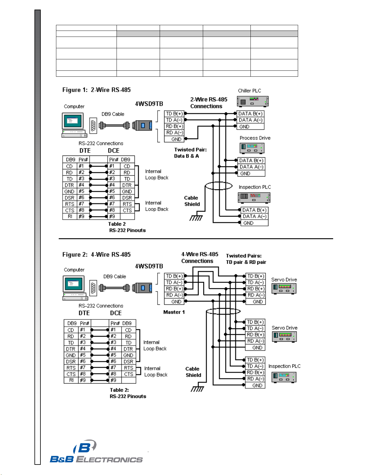
RS-485 2-Wire Half Duplex
This communications mode is used to connect several RS-485 devices to the same network with a
minimum number of wires when only one unit talks at a time. All units are normally in Receive mode,
listening for data. When data is requested, the addressed device waits (1 delay time) then transmits,
afterwards, goes back to receive. To use this mode set Switch 1: RS-485 , Switch 2: Echo Off, and
Switches 3 and 4 to 2-Wire. Refer to Figure 1 for connections.
RS-485 4-Wire Full Duplex
This mode is used for 4-Wire Master/Slave. Devices can be polled and respond faster, unlike half duplex
mode, no turn-around time delay is needed between requests and responses. The RS-485 driver works the
same as in haft duplex but the receiver is always enabled. This can allow devices to receive information
even while they are responding to a request. To use RS-485 4-Wire mode, set Switch 1: RS-485, Switch 2:
Echo On, and Switches 3 and 4 to 4-Wire. When the 4WSD9TB is used as a Master in a single master
system, Switch 1 can be set RS-422 since it is the only transmitter. When used for a Slave device, the RS232 device must provide addressability, and RS-485 mode should be selected. As in 2-Wire operation RS485 Biasing is provided on Receive, and should be provided on the transmit pair by the End-of-Line slave
device, RS-422 Transmit mode requires no bias on transmit. Refer to Figure 2 for Connections.
RS-422 4-Wire Full-Duplex or 2-Wire Simplex
This communications mode is typically used for point-to-point communications over long distances with
better noise immunity than RS-232. Another common use is as a single master in a master/slave
configuration, where the slave devices only receive, but don’t transmit back. In RS-422 the transmitter and
receiver are always enabled to allow full-duplex communications. Connections require one twisted pair for
Transmit, another twisted pair for Receive and a ground reference wirei for a total of 5 lines to operate
properly. To set this mode, Table 1: Switch 1: RS-422, Switch 2: Echo On, and Switches 3 and 4: 4-wire
Specifications
Signals:
o Transmit (TD) and Receive (RD)
o RTS and CTS are looped back, DTR., DSR & CD are looped back
Data Rates:
o Up to 115.2 kbps
Distance:
o Externally powered transmits up to 4000 ft (1200 m) at 115.2 kbps (may be less with port
powering)
Dimensions:
Temperature:
Troubleshooting Operation
If a RS-485 or RS-422 device doesn’t respond to data requests, try swapping the polarity of the data lines.
Some devices are marked opposite the RS-485 or RS-422 Standard. 4-Wire devices must swap polarity of
each pair. Operation of the converter can be checked with HyperTerminal. Set Converter to Loopback Test
mode. Open HyperTerminal using the Com port connected to, set baud rate, set Flow Control to None,
type characters. Each character should show as typed, two if local echo is on. For more info, visit our
website, Technical Library, FAQ on Troubleshooting and Checking.
i
If you are concerned about creating ground loops by connecting grounds of units together, please check into B&B Electronics’ line of
optically isolated RS-232 to RS-422/485 units such as the 485OT9L.
This product is Designed and Manufactured in the USA of domestic and imported components.
o 3.6 x 1.7 x 0.9 in (9.0 x 4.3 x 2.3 cm)
o 0-70 C
Page 5

4WSD9TB-0712 - p5/5
www.bb-elec.com orders@bb-elec.com support@bb-elec.com
International Office: 707 Dayton Road PO Box 1040 Ottawa, IL 61350 USA 815-433-5100 Fax 433-5104
European Office: Westlink Commercial Park Oranmore Co. Galway Ireland +353 91 792444 Fax +353 91 792445
PRODUCT INFORMATION B&B ELECTRONICS
DECLARATION OF CONFORMITY
Manufacturer’s Name: B&B Electronics Manufacturing Company
Manufacturer’s Address: P.O. Box 1040
707 Dayton Road
Ottawa, IL 61350 USA
Model Number: 4WSD9TB
Description: RS-422/485 Converter
Type: Light industrial ITE equipment
Application of Council Directive: 89/336/EEC
Standards: EN 55022
EN 61000-6-1
EN 61000 (-4-2, -4-3, -4-4, -4-5, -4-6, -4-8, -4-11)
Michael J. Fahrion, Director of Engineering
 Loading...