

Page 1
© 2003 by B&B Electronics. All rights reserved.
www.bb-elec.com orders@bb-elec.com support@bb-elec.com
International Office: 707 Dayton Road PO Box 1040 Ottawa, IL 61350 USA 815-433-5100 Fax 433-5104
European Office: Westlink Commercial Park Oranmore Co. Galway Ireland +353 91 792444 Fax +353 91 792445
PRODUCT INFORMATION B&B ELECTRONICS
Table 1:
RS-232 Pinout
Pin # Signal
1 DCD
2 RD
3 TD
4 DTR
5 GND
6 DSR
7 RTS
8 CTS
Table 2:
RS-422/485 Pinout
Pin # Signal
2 RD(A)3 TD(B)+
4 GND
6 GND
7 RD(B)+
8 TD(A)-
4WSD9R0712-1/4
Model 4WSD9R
Universal Converter
Covers All the Bases-
RS-232 to 4-wire RS-422,
2-wire or 4-wire RS-485
The 4WSD9R Universal Converter is a port-powered or externally powered two-channel RS-232 to RS-422/RS-485
converter. It converts TD and RD RS-232 lines to balanced RS-422 or RS-485 signals. RS-485 is an enhanced version
of the RS-422 standard, allowing multiple drivers and receivers on a two-wire system. The unit is powered from the RS232 data and handshake lines whether the lines are high or low. Or, if there is not enough power on the port, it can be
powered by an external +12VDC 100mA supply. The 4WSD9R has DB-9 female connectors on both the RS-232 side
and the RS-485 side. The RS-232 connector is configured as DCE (like a modem).
RS-232 Side:
Connector: DB-9 female (DCE)
Signals: Passes through pins 3 (TD) and 2 (RD)
Pins 7 (RTS) and 8 (CTS) are tied together
Pins 4 (DTR), 6 (DSR), and 1 (CD) are tied together
RS-422/RS-485 Side:
Connector: DB-9 female
Signals: RS-485 2-wire half-duplex, or RS-485 4-wire full-duplex,
or RS-422 4-wire full-duplex depending on switch configurations
Automatic control circuit enables driver only when transmitting
Receiver can be disabled when transmitting to prevent echo back to RS-232 device when in 2-wire mode
Data Rates: Up to 115.2 kbps
Distance: Externally powered transmits up to 4000 ft (1200 m) at 115.2 kbps (may be less with port powering)
Dimensions: 3.0 x 1.6 x 0.8 in (7.8 x 4.3 x 2.0 cm)
Power
No external power is required if two RS-232 output handshake lines are available and the cable
run is short. If the handshake lines are raised and no termination is used, the power efficiency is
greatly increased. Less than 3mA is required to operate the 4WSD9R plus the load current. For
applications that do not have handshake lines or require a large load current, power may be
externally supplied with a +12VDC power supply with a 2.5mm plug (tip positive).
RS-232 Operations
The RS-232 port has a female DB9 connector with pins 2 (RD), 3 (TD), and 5 (Signal Ground)
supported. Pins 7 (RTS) and 8 (CTS) are tied together, and pins 6 (DSR), 1 (DCD), and 4
(DTR) are also tied together. Any incoming data lines in either the high or low state are used to
port power the 4WSD9R. The more handshake lines available, the more likely the unit can be
port powered. Table 1 shows the RS-232 pinout.
RS-422/485 Operations
Although the 4WSD9R can use handshake lines to power the converter, no handshaking is
required to control the RS-422/RS-485 driver. With switch 1 set to RS-422, the driver is
always enabled. When switch 1 is in the RS-485 position, the RS-485 driver is automatically
enabled during each spacing state on the RS-232 side. During the marking or idle state, the
RS-485 driver is disabled and the data lines are held in the marking state by the 4.7K Ohm pullup and pull-down resistors. The value of these resistors may need to be changed to a different
value when termination is used in order to maintain the proper DC bias during the idle state.
Page 2
© 2003 by B&B Electronics. All rights reserved.
www.bb-elec.com orders@bb-elec.com support@bb-elec.com
International Office: 707 Dayton Road PO Box 1040 Ottawa, IL 61350 USA 815-433-5100 Fax 433-5104
European Office: Westlink Commercial Park Oranmore Co. Galway Ireland +353 91 792444 Fax +353 91 792445
PRODUCT INFORMATION B&B ELECTRONICS
Table 3: Switch settings for
RS-485 2-wire half-duplex
Switch # Position
1 RS-485
2 Echo Off
3 2-wire
4 2-wire
Table 4: Switch settings for
RS-485 4-wire full-duplex
Switch # Position
1 RS-485
2 Echo ON
3 4-wire
4 4-wire
9-pin M/F cable
See B&B Electronics’ free RS-422/RS-485 Application Note for more information on termination and DC biasing of an
RS-485 network.
4WSD9R0712-2/4
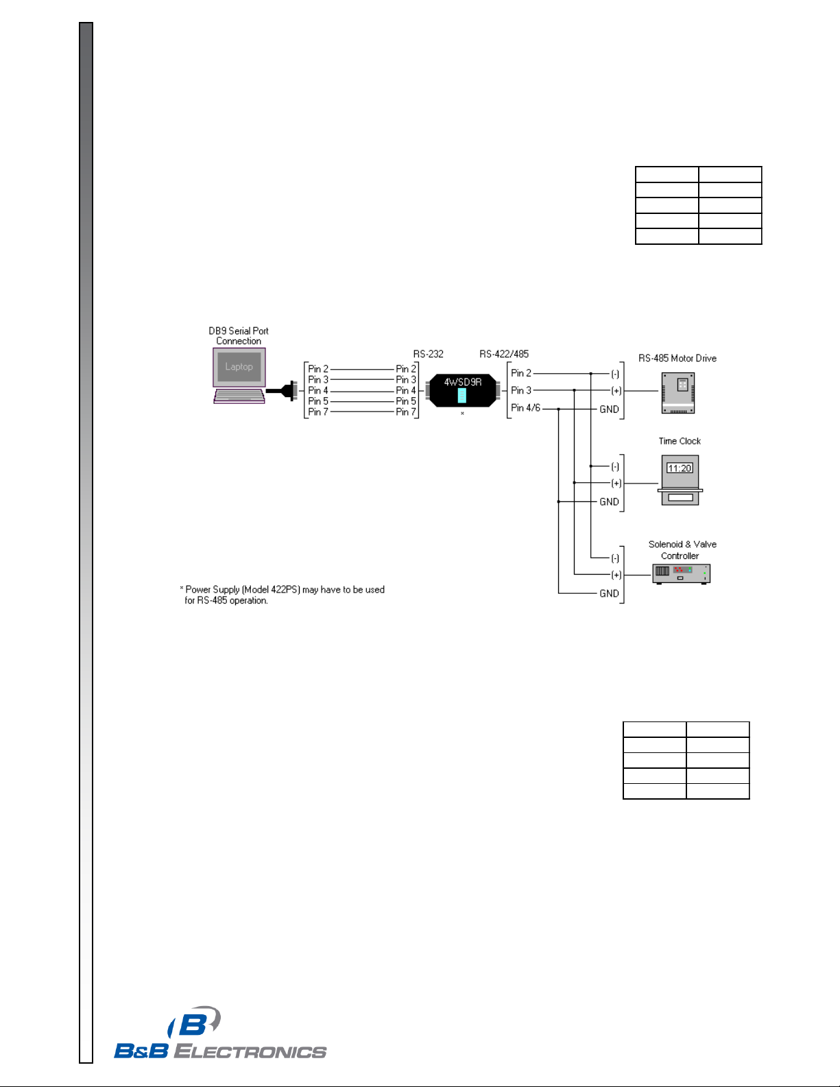
RS-485 2-Wire Half-Duplex
This communications mode is used to connect several RS-485 devices to the same
network with a minimum number of wires when only one unit talks at a time. The RS-485
driver is automatically enabled during each spacing state on the RS-232 side. During the
marking or idle state, the RS-485 driver is disabled and the data lines are held in the
marking state by the 4.7K Ohm pull-up and pull-down resistors. The value of these
resistors may need to be changed to a different value when termination is used in order
to maintain the proper DC bias during the idle state.
See B&B Electronics’ free RS-422/RS-485 Application Note for more information on
termination and DC biasing of an RS-485 network. To set up for this mode on the
4WSD9R, place switch 1 in the RS-485 position, switch 2 in the echo off position, and
switches 3 and 4 in the 2-wire position. Follow the wiring diagram in Figure1 to connect
to a 2-wire half-duplex network.
RS-485 4-Wire Full-Duplex
This communications mode is typically one of the slaves in a master/slave RS-485
setup. The RS-485 driver is automatically enabled during each spacing state on the
RS-232 side. During the marking or idle state, the RS-485 driver is disabled and the
data lines are held in the marking state by the 4.7K Ohm pull-up and pull-down
resistors. The value of these resistors may need to be changed to a different value
when termination is used in order to maintain the proper DC bias during the idle state.
See B&B Electronics’ free RS-422/RS-485 Application Note for more information on
termination and DC biasing of an RS-485 network.
The receiver is enabled at all times, allowing devices to receive information even while they are responding
to a request. To set up for this mode on the 4WSD9R, place switch 1 in the RS-485 position, switch 2 in the
echo on position, and switches 3 and 4 in the 4-wire position. The wiring between the slave and the master
is identical to the RS-422 4-wire full-duplex diagram shown in Figure 3, and in many cases the master in a
master/slave RS-485 network is set up as an RS-422 device. When multiple slaves are on the same
network, the connection between the master and each slave must be the same as shown in Figure 2. This
will cause all slaves to have their transmitters connected and their receivers connected, and not allow
communications between the slaves themselves.
Figure 1: RS-485 2-wire half-duplex diagram
Page 3

© 2003 by B&B Electronics. All rights reserved.
www.bb-elec.com orders@bb-elec.com support@bb-elec.com
International Office: 707 Dayton Road PO Box 1040 Ottawa, IL 61350 USA 815-433-5100 Fax 433-5104
European Office: Westlink Commercial Park Oranmore Co. Galway Ireland +353 91 792444 Fax +353 91 792445
PRODUCT INFORMATION B&B ELECTRONICS
Table 5: Switch settings for
RS-422 4-wire full-duplex
Switch # Position
1 RS-422
2 Echo On
3 4-wire
4 4-wire
9-pin M/F cable
9-pin M/F cable
4WSD9R0712-3/4
RS-422 4-Wire Full-Duplex:
This communications mode is typically used for point-to-point communications over long
distances with better noise immunity than RS-232. Another common use would be as the
master in a master/slave configuration. The RS-422 driver and receiver are always
enabled to allow full-duplex communications. In order to do this there must be a pair of
wires dedicated to the driver, a pair dedicated to the receiver, and a ground reference
wirei for a total of 5 lines to operate properly. To set up for this mode, put switch 1 in the
RS-422 position, switch 2 in the Echo On position, and switches 3 and 4 in the 4-wire
position as shown in Table 5.
_________________________
i
If you are concerned about creating ground loops by connecting grounds of units together, please check into
B&B Electronics’ line of optically isolated RS-232 to RS-422/485 units such as the 485OT9L.
Figure 2: RS-485 4-wire full-duplex diagram
Figure 3: RS-422 4-wire full-duplex diagram
Page 4

© 2003 by B&B Electronics. All rights reserved.
www.bb-elec.com orders@bb-elec.com support@bb-elec.com
International Office: 707 Dayton Road PO Box 1040 Ottawa, IL 61350 USA 815-433-5100 Fax 433-5104
European Office: Westlink Commercial Park Oranmore Co. Galway Ireland +353 91 792444 Fax +353 91 792445
PRODUCT INFORMATION B&B ELECTRONICS
DECLARATION OF CONFORMITY
Manufacturer’s Name: B&B Electronics Manufacturing Company
Manufacturer’s Address: P.O. Box 1040
707 Dayton Road
Ottawa, IL 61350 USA
Model Number: 4WSD9R
Description: RS-422/485 Converter
Type: Light industrial ITE equipment
Application of Council Directive: 89/336/EEC
Standards: EN 55022
EN 61000-6-1
EN 61000 (-4-2, -4-3, -4-4, -4-5, -4-6, -4-8, -4-11)
Robert M. Paratore, Director of Engineering
4WSD9R0712-4/4
This product is Designed and Manufactured in the USA of domestic and imported components.
 Loading...