

Page 1
P#9150_4WSDxxOTB-0812ds - p1/4
www.bb-elec.com orders@bb-elec.com support@bb-elec.com
International Office: 707 Dayton Road PO Box 1040 Ottawa, IL 61350 USA 815-433-5100 Fax 433-5104
European Office: Westlink Commercial Park Oranmore Co. Galway Ireland +353 91 792444 Fax +353 91 792445
PRODUCT INFORMATION B&B ELECTRONICS
Model Number
Description
4WSD9OTB
Converter with female DB9 RS-232 Connector
4WSD25OTB
Converter with female DB25 RS-232 Connector
7175
Power 2-position Terminal Block – one included
7372
Data 5-position Terminal Block – one included
9PAMF6
6ft. Serial Cable DB9M to DB9F
485PS2
120 VAC to 12 VDC Power Supply
PS2EU-1000
220/240 VAC to 12 VDC Power Supply; 2-Prong Euro Plug
PS2UK-1000
220/240 VAC to 12 VDC Power Supply; 3-Prong UK Plug
Models: 4WSD9OTB/4WSD25OTB
Isolated Universal Converters
RS-232, 4-wire RS-422, 2-wire or 4-wire RS-485
Features
High Speed Communications. Supports data rates up to 115.2 kbps.
Extended communications. Supports distances up to 4000 ft (1200 m).
Removable terminal blocks for easy RS-422/RS-485 connections.
Switchable modes. Supports 2-wire RS-485, 4-wire RS-485, and full duplex RS-422.
Automatic RS-485 driver control. External software modifications are not required.
2000 VAC isolation. Reliable in harsh electrical conditions.
Functional Description
Isolates and converts RS-232 signals into RS-422 / RS-485 signals and vice versa. Unlike other
converters, external software is not required to control data flow. The RS-232 input is wired for DCE and
interfaced through a female DB25 or DB9 connector. RS-422 or RS-485 signals are connected to a
removable terminal block. External power is applied to separate removable terminal block. A 10 – 48 VDC
power supply (not included) is required.
Ordering Information
Page 2
P#9150_4WSDxxOTB-0812ds - p2/4
www.bb-elec.com orders@bb-elec.com support@bb-elec.com
International Office: 707 Dayton Road PO Box 1040 Ottawa, IL 61350 USA 815-433-5100 Fax 433-5104
European Office: Westlink Commercial Park Oranmore Co. Galway Ireland +353 91 792444 Fax +353 91 792445
PRODUCT INFORMATION B&B ELECTRONICS
Switches
Switch 1 (Tx)
Switch 2 (Rx)
Switch 3
(bridge)
Switch 4
(bridge)
Operating Mode
RS-485 2-Wire Mode
(half duplex)
RS-485
Echo Off
2-Wire
2-Wire
RS-485 4-Wire Mode
(full duplex)
RS-485
Echo On
4-Wire
4-Wire
RS-422 4-Wire Mode
(full duplex)
RS-422
Echo On
4-Wire
4-Wire
Loopback Test Mode*
As Desired
Echo On
2-Wire
2-Wire
Operation
Configure operating mode using guidance in Table 1.
Common Applications are discussed in Figures 1 through 3.
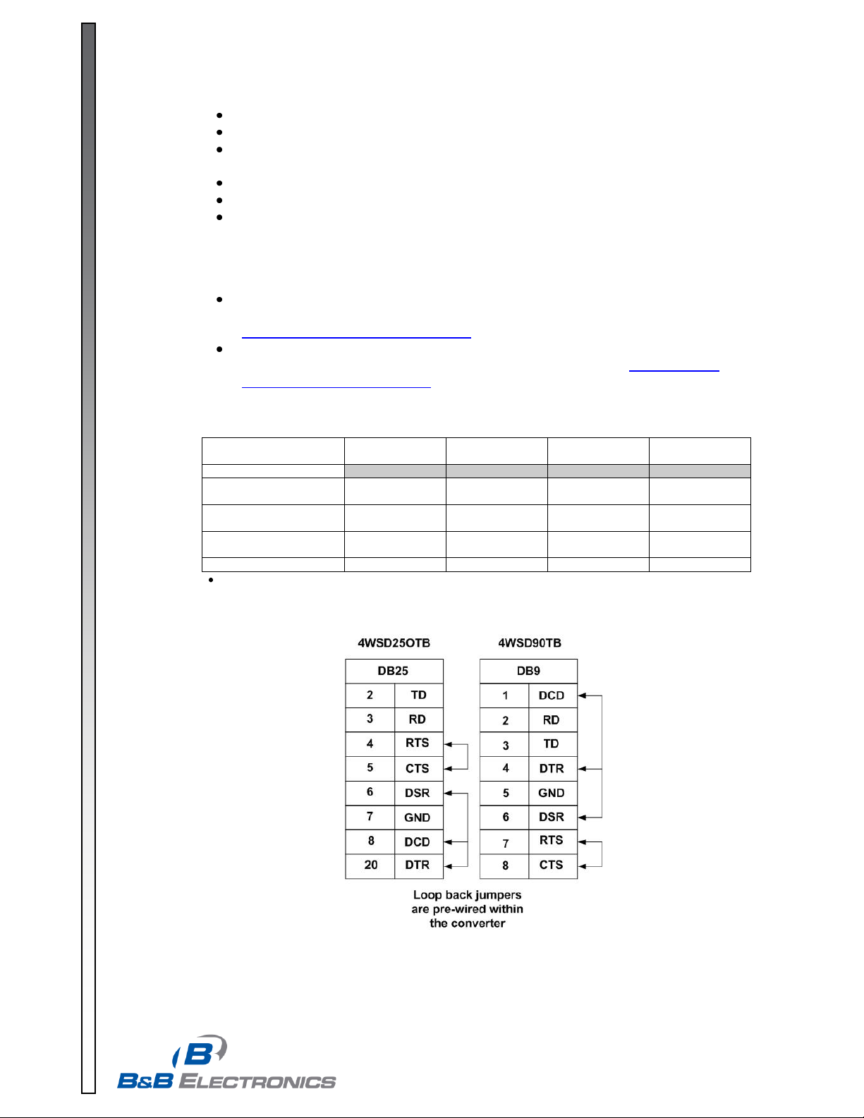
RS-232 connection requires RD, TD, and Signal Ground. The remaining signals are
looped back within the converter as shown in Table 2.
In half duplex operation, the receiver is enabled when not transmitting (Echo Off).
In RS-422 mode, the driver is always enabled.
In RS-485 mode, the RS-485 driver is automatically enabled during each space state by
the presence of an RS-232 signal. When the RS-232 data is in a mark or idle state, the RS-
485 driver is disabled and the RS-485 data lines are held in a mark state by the bias
provided by a 4.7K Ω resistor. The value of this resistor may need to be changed
depending on the termination used.
Refer to B&B Electronics’ RS-422/RS-485 Application Note for detailed information
concerning RS-422 and RS-485 networks. This document is available for download at
http://www.bb-elec.com/tech_articles.
The loopback test mode switch is used with hyper terminal to verify the operation of the
converter. Additional troubleshooting guidance is available at http://www.bb-
elec.com/technical_library.asp.
Table 1 – Operating Mode Switch Settings
Used with HyperTerminal or another terminal program to confirm operation of data through converter.
Table 2 – RS-232 Pin-out
Page 3

P#9150_4WSDxxOTB-0812ds - p3/4
www.bb-elec.com orders@bb-elec.com support@bb-elec.com
International Office: 707 Dayton Road PO Box 1040 Ottawa, IL 61350 USA 815-433-5100 Fax 433-5104
European Office: Westlink Commercial Park Oranmore Co. Galway Ireland +353 91 792444 Fax +353 91 792445
PRODUCT INFORMATION B&B ELECTRONICS
Figure 1: 2-Wire RS-485
Used to connect several RS-485
devices with minimal wire.
Devices communicate one at a time.
Units are normally in receive mode.
When data is requested, the
addressed device waits one delay
time before responding.
After transmitting, the device reverts
to receive.
Switch settings are: Switch 1: RS-
485, Switch 2: Echo Off, Switches 3
and 4 to 2-Wire.
Figure 2: 4-Wire RS-485
Used for 4-Wire Master/Slave
circuits.
Each device is polled, allowing
faster response time.
Addressed devices can receive
while responding to a request.
When used as a Master in a single
master system, Switch 1 may be
set RS-422 since it is the only
transmitter.
When used as a slave, the RS-232
device must provide addressability.
Select RS-485 mode in this
situation.
Biasing is provided by the end-of-line slave.
Switch settings for this mode are : Switch 1:
RS-485, Switch 2: Echo On, Switches 3 and
4: 4-wire.
Page 4
P#9150_4WSDxxOTB-0812ds - p4/4
www.bb-elec.com orders@bb-elec.com support@bb-elec.com
International Office: 707 Dayton Road PO Box 1040 Ottawa, IL 61350 USA 815-433-5100 Fax 433-5104
European Office: Westlink Commercial Park Oranmore Co. Galway Ireland +353 91 792444 Fax +353 91 792445
PRODUCT INFORMATION B&B ELECTRONICS
Input Power Requirement
10 – 48 VDC
Isolation
2000 VAC
Current Draw
28 mA at 12 VDC (typical)
RS-232 Connection
DB9/DB25
RS-422/RS-485
Connection
Removable Terminal
Block
Data Rate
Up to 115.2 kbps
Operating Temperature
32 – 158°F (0 - 70°C)
LED Indicators
TD and RD
Dimensions
(4WSD9OTB)
3.9 x 1.7 x 0.9 in
9.8 x 4.3 x 2.3 cm
Dimensions
(4WSD25OTB)
3.9 x 2.2 x 0.9 in
9.8 x 5.5 x 2.3 cm
Approvals
CE
DECLARATION OF CONFORMITY
Manufacturer’s Name: B&B Electronics Manufacturing Company
Manufacturer’s Address: P.O. Box 1040
707 Dayton Road
Ottawa, IL 61350 USA
Model Number: 4WSDxxOTB
Description: RS-422/485 Converter
Type: Light industrial ITE equipment
Application of Council Directive: 89/336/EEC
Standards: EN 55022
EN 61000-6-1
EN 61000 (-4-2, -4-3, -4-4, -4-5, -4-6, -4-8, -4-11)
Michael J. Fahrion, Director of Engineering
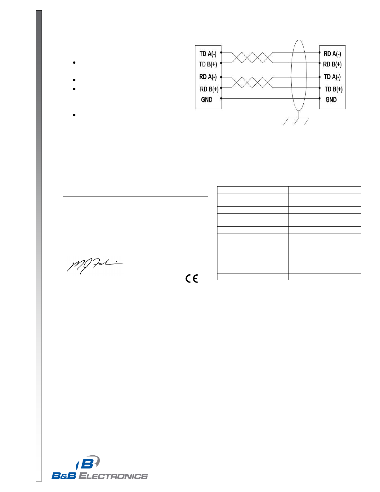
Figure 3: 4-wire RS-422
Used as the master in a master/slave
circuit with receive only slaves.
Full-duplex communications.
Requires a twisted pair for transmit, a
twisted pair for receive, and a ground
reference wire.
Switch settings are: Switch 1: RS-
422, Switch 2: Echo On, Switches 3
and 4: 4-wire.
Specifications
 Loading...