

Page 1
Documentation Number –p/n 8677R1 232CLDR-3512qsg
22.. UULL IInnssttaallllaattiioonn IInnffoorrmmaattiioonn
Underwriters Laboratories Conditions of Acceptability –
When installed in the end-use equipment, consideration
should be given to the following:
1. The wiring terminals are suitable for factory wiring only.
2. This device is to be mounted in a suitable enclosure in
the end-product.
3. This device is suitable for operation at a maximum
surrounding air temperature as described in the
documentation.
4. These devices are intended for use in a pollution
degree 2 environment.
Input Voltage: 10 – 30 VDC
Input Power: 2.5 Watts
Wire Range: 12 – 24 AWG
Tightening Torque: 4 kgf-cm
Temperature rating of field installed conductors is 105 C
minimum, sized for 60 C ampacity.
Use copper wire only
Maximum surrounding ambient air temperature 80 C.
11.. RReeqquuiirreedd HHaarrddwwaarree
232CLDR Optically Isolated RS-232 to Current Loop
Converter
This Quick Start Guide
Additional Items Required but not included
o Power Supply (10 to 30 VDC, 2.5 W)
o Cabling
Quick Start Guide
232CLDR
Optically Isolated RS-232 to
Current Loop Converter
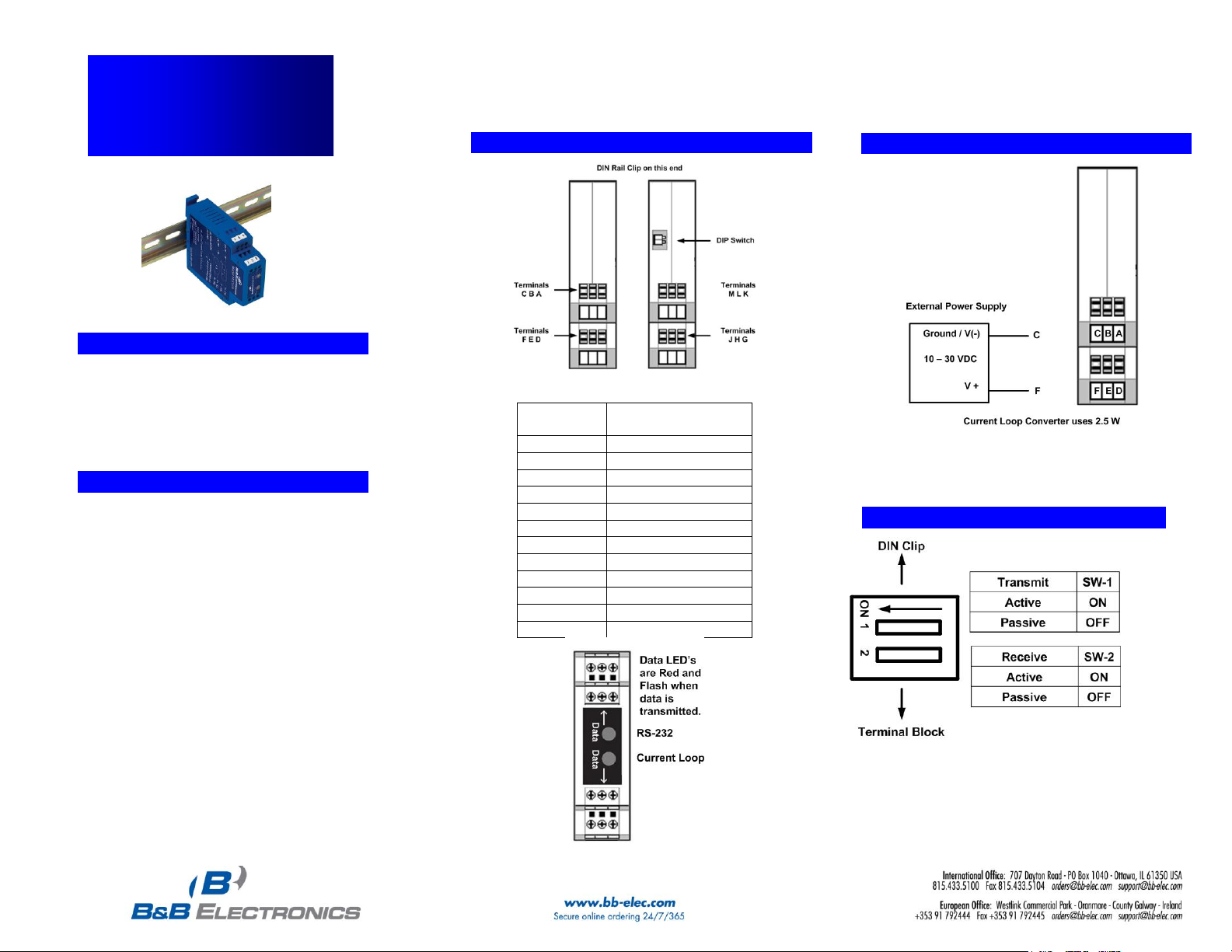
44.. PPoowweerr CCoonnnneeccttiioonn
33.. IInnffoorrmmaattiioonn
–
–
CCoonnnneeccttoorrss && IInnddiiccaattoorrss
Terminal
Block
Signal
A
RS-232 RD (Output)
B
Not Used
C
Ground
D
RS-232 TD (Input)
E
Not Used
F
+10 to 30 VDC
G
T(-) H T(+) J Current Ground
K
R(-)
L
R(+)
M
Current Ground
55.. DDIIPP SSwwiittcchh
©2012 B&B Electronics Manufacturing Company
Put
Page 2
Documentation Number –p/n 8677R1 232CLDR-3512qsg
88.. TTeesstt // TTrroouubblleesshhoooott
Connect your PC to the RS-232 side.
Place a jumper between Terminal G & L and
Terminal H & J.
Using hyper terminal or similar program, connect
to the appropriate COM port. Turn off hyper
terminal local echo.
Transmit data. The same data should be returned.
Data LED will indicate data being transmitted.
3. To determine if your current loop device is
“active” or “passive” a multi-meter is required.
Set the meter to DC Volts and put the positive
(red) lead on the T+ line and the negative
(black) lead on the T- line of the current loop
device. If a voltage is displayed on the meter,
your device is active.
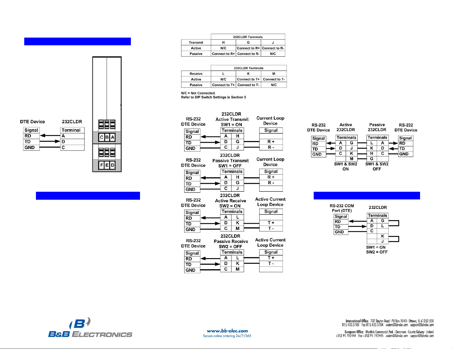
4. The following is an example of how to extend
RS-232 using two 232CLDR Current Loop
Converters. The converter on the left is
configured as “active” the converter on the right
is configured as “passive.”
66.. RRSS--223322 CCoonnnneeccttiioonnss
77.. CCuurrrreenntt LLoooopp CCoonnnneeccttiioonnss
1. The 232CLDR has one optically isolated 20 mA
transmit loop and one optically isolated 20 mA receive
loop. Each loop can be set to either “Active” or
“Passive. When set to “Active” an isolated 20 mA
current is supplied for each loop (transmit and
receive). The same power supply provides power to
the converter and both current loops.
2. The 232CLDR can communicate at baud rates up to
19.2 kbps and distances up to 2000 ft (600 m).
©2012 B&B Electronics Manufacturing Company
 Loading...