

B&B VESR901-ST, VESR902T, VESR901-ST40, VESR901-ST80, VESR902D User Manual
...
VESR9xx
Serial servers

2
International Headquarters
B+B SmartWorx.
707 Dayton Road
Ottawa, IL 61350 USA
Phone (815) 433-5100 -- General Fax (815) 433-5105
Website: www.bb-smartworx.com
support@bb-smartworx.com
European Headquarters
B+B SmartWorx
Westlink Commercial Park
Oranmore, Co. Galway, Ireland
Phone +353 91-792444 -- Fax +353 91-792445
Document: VESR9xx _3615m

3
CONTENTS
Introduction ................................................................................................................. 6
ABOUT VESR9XX SERIAL SERVERS ................................................................................ 6
VESR9XX SERIAL SERVER MODEL NUMBERING ........................................................... 7
LIST OF VESR9XX SERIAL SERVER MODELS .................................................................. 8
VESR9XX SERIAL SERVER FEATURES .......................................................................... 10
VLINX MANAGER CONFIGURATION SOFTWARE ........................................................ 10
VESR9XX SERIAL SERVER HARDWARE .................................................................... 11
PACKAGE CHECKLIST ................................................................................................... 11
VESR9XX SERIAL SERVER ENCLOSURES AND MOUNTING......................................... 11
LED INDICATORS(VESR90X) ........................................................................................ 12
LINK LED ............................................................................................................... 12
READY LED ........................................................................................................... 12
SERIAL PORT LEDS .............................................................................................. 12
LED INDICATORS (VESR92X) ....................................................................................... 12
MODE SWITCH ............................................................................................................. 13
ETHERNET CONNECTOR ............................................................................................... 14
FIBER OPTIC CONNECTORS ......................................................................................... 15
SERIAL PORT CONNECTORS ........................................................................................ 15
POWER CONNECTOR .................................................................................................... 16
MOUNTING HARDWARE .............................................................................................. 17
SERIAL SERVER SETUP AND CONNECTIONS ........................................................... 17
CONNECTING THE POWER SUPPLY ............................................................................. 17
CONNECTING VESR9XX SERIAL SERVERS TO SERIAL DEVICES ................................. 18
CONNECTING THE VESR901-X ......................................................................... 19
CONNECTING THE VESR902T-X ....................................................................... 19
CONNECTING THE VESR902D-X ...................................................................... 20
CONNECTING VESR9XX SERIAL SERVERS TO A NETWORK ........................................ 21
NETWORK CONNECTION (10BASET/100BASETX) ....................................... 21
FIBER OPTIC CONNECTION ............................................................................... 21
VESR9XX SERIAL SERVER CONFIGURATION CONNECTIONS ..................................... 22
CONFIGURING THE VESR9XX SERIAL SERVER VIA THE NETWORK
CONNECTION ....................................................................................................... 22
CONFIGURING THE VESR9XX SERIAL SERVER VIA THE SERIAL PORT
(CONSOLE MODE) ............................................................................................... 23
VESR9XX SERIAL SERVER OPERATIONAL CONNECTIONS .......................................... 24
USING VESR9XX SERIAL SERVERS IN DIRECT IP MODE ............................. 25
USING VESR9XX SERIAL SERVERS IN VIRTUAL COM PORT MODE .......... 25
USING VESR9XX SERIAL SERVERS IN PAIRED MODE .................................. 26
INITIATING A HARDWARE RESET ON THE SERIAL SERVER ....................................... 27
RELOADING FACTORY DEFAULTS ................................................................................ 27
Description of Serial Server Properties ................................................................... 28

4
BAUD RATE ................................................................................................................... 28
CHARACTER COUNT ..................................................................................................... 28
CONFIGURATION FILES ................................................................................................ 28
DATA/PARITY/STOP ..................................................................................................... 28
DEFAULT GATEWAY ..................................................................................................... 29
DELIMITER 1, DELIMITER 2 AND DELIMITER REMOVAL ........................................... 29
DELIMITER 1 ........................................................................................................ 29
DELIMITER 2 ........................................................................................................ 29
DELIMITER REMOVAL ........................................................................................ 29
HOW DELIMITERS WORK .................................................................................. 30
DHCP ............................................................................................................................. 30
FIRMWARE VERSION ................................................................................................... 31
FLOW CONTROL ........................................................................................................... 31
FORCED TRANSMIT ...................................................................................................... 31
HARDWARE VERSION ................................................................................................... 31
INTER- CHARACTER TIMEOUT ...................................................................................... 31
IP ADDRESS .................................................................................................................. 32
LINK STATUS ................................................................................................................. 34
MAC ADDRESS .............................................................................................................. 34
MODEL .......................................................................................................................... 35
NETWORK PROTOCOLS ................................................................................................ 35
NETWORK WATCHDOG ................................................................................................ 35
PAIRED MODE .............................................................................................................. 35
PASSWORD ................................................................................................................... 36
SERIAL INTERFACE MODES ......................................................................................... 36
SERIAL SERVER NAME ................................................................................................. 37
SERVER SERIAL PORT NUMBER................................................................................... 37
SERIAL WATCHDOG ..................................................................................................... 37
SUBNET MASK .............................................................................................................. 37
TCP (TRANSMISSION CONTROL PROTOCOL) .............................................................. 38
UDP (USER DATAGRAM PROTOCOL) .......................................................................... 38
VCOM (VIRTUAL COM PORT) ...................................................................................... 39
UPGRADING THE SERIAL SERVER FIRMWARE ........................................................ 39
DOWNLOADING FIRMWARE FILES .............................................................................. 40
UPLOADING THE FIRMWARE TO THE SERIAL SERVER .............................................. 40
Diagnostics ................................................................................................................ 42
TESTING A SERIAL SERVER CONNECTION .................................................................. 42
TESTING A VIRTUAL COM PORT ................................................................................. 43
Appendix A: Default Server Settings ....................................................................... 45
APPENDIX B: PRODUCT SPECIFICATIONS ............................................................... 46
GENERAL SPECIFICATIONS ............................................................................... 46
CONTROLS, INDICATORS AND CONNECTOR SPECIFICATIONS ................. 48
SERIAL INTERFACE SPECIFICATIONS .............................................................. 49
NETWORK SPECIFICATIONS ............................................................................. 50

5
Appendix C: Dimensional Diagrams ........................................................................ 51
APPENDIX D: CONNECTOR PINOUTS ....................................................................... 55
VESR901 & VESR921 SERIES ............................................................................ 55
VESR902D SERIES ............................................................................................... 57
VESR902T & VESR922T SERIES........................................................................ 58
STANDARD ETHERNET CABLE RJ-45 PIN-OUT ............................................. 59
B&B SMARTWOR X TECHNICAL SUPPORT ................................................... 60

6
INTRODUCTION
Thank you for purchasing a VESR9xx Serial Server product! This product has been
manufactured to the highest standards of quality and performance to ensure your
complete satisfaction.
A VESR902T Serial Server
ABOUT VESR9XX SERIAL SERVERS
VESR9xx Serial Servers connect serial devices (RS-232, RS-422 or RS-485) to Ethernet
networks, allowing the serial device to become a node on the network. The serial
ports can be accessed over a LAN/WAN using Direct IP Mode, Virtual COM Port, or
Paired Mode connections. VESR9xx Serial Servers feature 10BaseT or 100BaseTX
copper network media and several fiber optic media options, depending on the
model. VESR92x serial servers feature an additional copper Ethernet pass-through
port. VESR9xx Serial Servers are built for use in industrial environments, featuring an
IP30 approved slim line DIN rail mountable case. They operate from a range of DC
power supply voltages and feature pluggable terminal block power connectors.
7
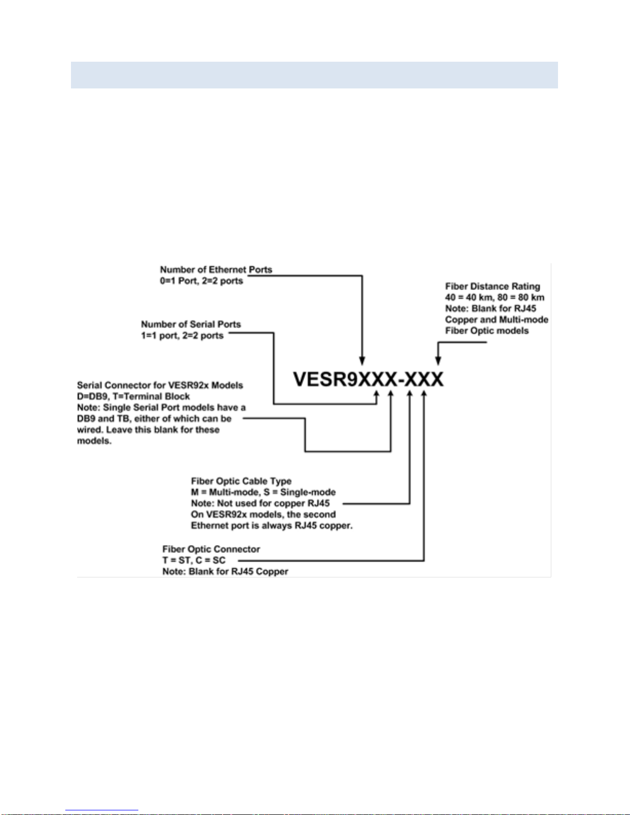
VESR9XX SERIAL SERVER MODEL NUMBERING
VESR9xx Serial Server are a growing family of products. Models are available with
one or two serial connections and one or two Ethernet connections. Network
connection options include 10BaseT/100BaseTX copper or several different fiber
optic options (on models with a pass-through port, the pass-through port is copper).
The following diagram shows the model numbering scheme:

8
LIST OF VESR9XX SERIAL SERVER MODELS
The following table lists the various VESR9xx Serial Server models available.
Model Number Features
VESR901
Vlinx , 1PORT, DB9, ESS, DIN, CU ETHERNET
VESR901-SC40
Vlinx , 1PORT, DB9, ESS, DIN, FIBER, SC, 40KM
VESR901-SC80
Vlinx , 1PORT, DB9, ESS, DIN, FIBER, SC, 80KM
VESR901-ST
Vlinx , 1PORT, DB9, ESS, DIN, FIBER, ST
VESR901-ST40
Vlinx , 1PORT, DB9, ESS, DIN, FIBER, ST, 40KM
VESR901-ST80
Vlinx , 1PORT, DB9, ESS, DIN, FIBER, ST, 80KM
VESR902D
Vlinx , 2PORT, DB9, ESS, DIN, CU ETHERNET
VESR902D-SC40
Vlinx , 2PORT, DB9, ESS, DIN, FIBER, SC, 40KM
VESR902D-SC80
Vlinx , 2PORT, DB9, ESS, DIN, FIBER, SC, 80KM
VESR902D-ST40
Vlinx , 2PORT, DB9, ESS, DIN, FIBER, ST, 40KM
VESR902D-ST80
Vlinx , 2PORT, DB9, ESS, DIN, FIBER, ST, 80KM
VESR902T
Vlinx , 2PORT, TB, ESS, DIN, CU ETHERNET
VESR902T-SC
Vlinx , 2PORT, TB, ESS, DIN, FIBER, SC
VESR902T-SC40
Vlinx , 2PORT, TB, ESS, DIN, FIBER, SC, 40KM
VESR902T-SC80
Vlinx , 2PORT, TB, ESS, DIN, FIBER, SC, 80KM
VESR902T-ST
Vlinx , 2PORT, TB, ESS, DIN, FIBER, ST
VESR902T-ST40
Vlinx , 2PORT, TB, ESS, DIN, FIBER, ST, 40KM
VESR902T-ST80
Vlinx , 2PORT, TB, ESS, DIN, FIBER, ST, 80KM
VESR902T-MC
Vlinx , 2PORT, TB, ESS, DIN, FIBER, MULTIMODE, SC
VESR902T-MT
Vlinx , 2PORT, TB, ESS, DIN, FIBER, MULTIMODE, ST
VESR921
VLINX, 1PORT, DB9, ESS, DIN, 2 CU ETHE RNET
VESR921-MC
VLINX, 1PORT, DB9, ESS, DIN, FIBER, MULTI, SC, CU
VESR921-MT
VLINX, 1PORT, DB9, ESS, DIN, FIBER, MULTI, ST, CU
VESR921-SC
VLINX, 1PORT, DB9, ESS, DIN, FIBER, SC, CU
VESR921-SC40
VLINX, 1PORT, DB9, ESS, DIN, FIBER, SC, 40KM, CU
VESR921-SC80
VLINX, 1PORT, DB9, ESS, DIN, FIBER, SC, 80KM, CU
VESR921-ST
VLINX, 1PORT, DB9, ESS, DIN, FIBE R, ST, CU
VESR921-ST40
VLINX, 1PORT, DB9, ESS, DIN, FIBER, ST, 40KM, CU

9
Model Number Features
VESR921-ST80
VLINX, 1PORT, DB9, ESS, DIN, FIBER, ST, 80KM, CU
VESR922T
VLINX, 2PORT, TB, ESS, DIN, 2 CU ETHER NET
VESR922T-MC
VLINX, 2PORT, TB, ESS, DIN, FIBER, MULTI, SC, CU
VESR922T-MT
VLINX, 2PORT, TB, ESS, DIN, FIBER, MULTI, ST, CU
VESR922T-SC
VLINX, 2PORT, TB, ESS, DIN, FIBER, SC, CU
VESR922T-SC40
VLINX, 2PORT, TB, ESS, DIN, FIBER, SC, 40KM, CU
VESR922T-SC80
VLINX, 2PORT, TB, ESS, DIN, FIBER, SC, 80KM, CU
VESR922T-ST
VLINX, 2PORT, TB, ESS, DIN, FIBER, ST, CU
VESR922T-ST40
VLINX, 2PORT, TB, ESS, DIN, FIBER, ST, 40KM, CU
VESR922T-ST80
VLINX, 2PORT, TB, ESS, DIN, FIBER, ST, 80KM, CU

10
VESR9XX SERIAL SERVER FEATURES
Three series models
VESR9x1-x (single serial port)
VESR9x2D-x (two serial ports with DB9M)
VESR9x2T-x (two serial ports with pluggable terminal blocks)
Fiber models available for each of the above series
Ethernet pass through ports are available on VESR92x series models.
Multi-interface serial ports
DB-9M and pluggable terminal block serial port connector options
All ports are software selectable as RS-232, RS-422 or RS-485 2- and 4-wire
Configuration can be done via network or direct serial connection
Slim line DIN rail mountable case
Accepts DC power over a wide voltage range
10/100 Mbps Ethernet with Auto Selection
LAN and WAN Communications
TCP Client or Server, or UDP operation - configurable
Virtual COM port and Paired Mode capabilities
Firmware Upload for future revisions/upgrades
Software Support - Windows 2000, XP (32/64 bit), 2003 Server (32/64 bit), Vista
(32/64 bit), 2008 Server (32/64 bit), Windows 7 (32/64 bit)
Configuration of Ethernet and serial port settings using Vlinx Manager software
VLINX MANAGER CONFIGURATION SOFTWARE
Vlinx Manager configuration software enables you to find connected serial servers,
configure them, upgrade serial server firmware, and save/load configuration files. It
features a graphical user interface (GUI) that is convenient and easy to use. The
software also makes it easy to add and remove virtual COM ports on your computer.

11
VESR9XX SERIAL SERVER HARDWARE
VESR9xx Serial Servers are enclosed in DIN rail mountable enclosures and feature
LED indicators, power, Ethernet and serial connectors and a recessed Mode switch.
PACKAGE CHECKLIST
VESR9xx Serial Servers are shipped with the following items included:
VESR9xx Serial Server Module
Quick Start Guide
VESR9XX SERIAL SERVER ENCLOSURES AND MOUNTING
All VESR9xx Serial Server models are built into similar enclosures. Modules are DIN
rail mountable.
Front View of the VESR922T and VESR902T Serial Server
12
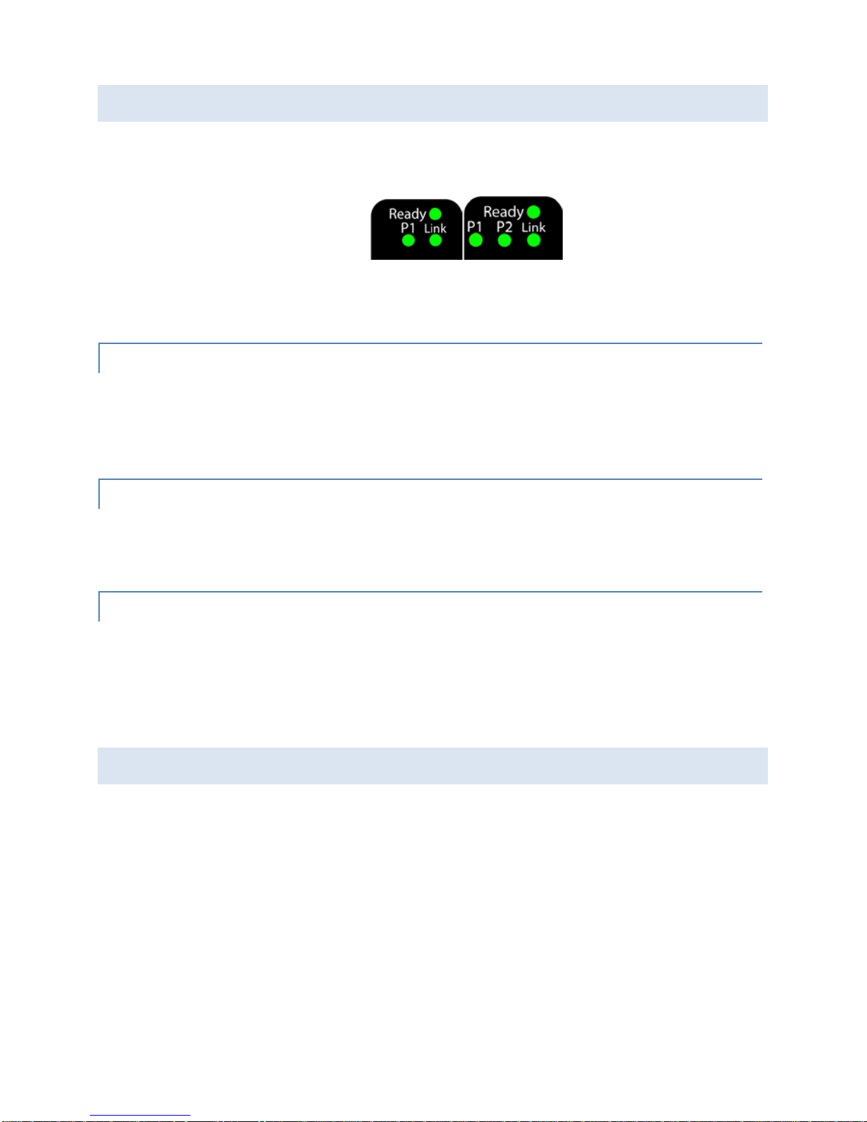
LED INDICATORS(VESR90X)
VESR9xx Serial Servers have three LED indicators: a Link LED, a Ready LED and two
Serial Port LEDs.
LEDs on 1 and 2 Port Serial Servers
LINK LED
The Link LED illuminates (green) if the Ethernet connection is operating in 100BaseTX
mode. The LED is off if the mode is 10BaseT. When the LED is blinking it indicates
that there is data traffic on the Ethernet link.
READY LED
The Ready LED (green) blinks once per second if the system is operating correctly. If
the LED is off, it indicates the system is not operating correctly.
SERIAL PORT LEDS
VESR901-x serial servers feature one serial port. VESR902D,and VESR902T-x serial
servers feature two serial ports. Each serial port has an associated LED. Serial Port
LEDs blink (green) when data is being transmitted or received on the serial port.
When the LED is On it indicates the serial port is open.
LED INDICATORS (VESR92X)
VESR92x Serial Servers have four LED indicators: E1 and E2 LEDs, a Ready LED and
two Serial Port LEDs.

13
LEDs on 1 and 2 Port Serial Servers
E1 and E2 LEDs
The E1 and E2 LEDs illuminate (green) if the Ethernet connection is operating in
100BaseTX mode. The LEDs are off if the mode is 10BaseT. When the LED is blinking
it indicates that there is data traffic on the Ethernet link.
Ready LED
The Ready LED (green) blinks once per second if the system is operating correctly. If
the LED is off, it indicates the system is not operating correctly.
Serial Port LEDs
VESR921-x serial servers feature one serial port. VESR922x, serial servers feature two
serial ports. Each serial port has an associated LED. Serial Port LEDs blink (green)
when data is being transmitted or received on the serial port. When the LED is On it
indicates the serial port is open.
MODE SWITCH
A recessed momentary reset switch is located on the top of the enclosure. To
activate the switch, insert a small plastic tool through the hole in the enclosure and
press lightly.

14
Top View of the Serial Server
The Mode switch can be used to:
Initiate a Hardware Reset
Enter Console Mode
Reload factory defaults
Note: Refer to Sec tion 3. S erial Server Setu p and Co nnecti ons for mor e inform atio n on using
the Mode switch.
ETHERNET CONNECTOR
Serial server models using 10BaseT/100BaseTX network connections use an RJ45
receptacle. The serial server is connected to a standard Ethernet network drop using
a straight-through RJ45 (male) Ethernet cable. VESR92x models feature a second
RJ45 receptacle which acts an Ethernet pass-through connection. This connection
functions similar to an Ethernet switch and allows the connection of other devices to
the network.
Ethernet Connector
Note: Refer to Appendix D for connection pin-outs.
15
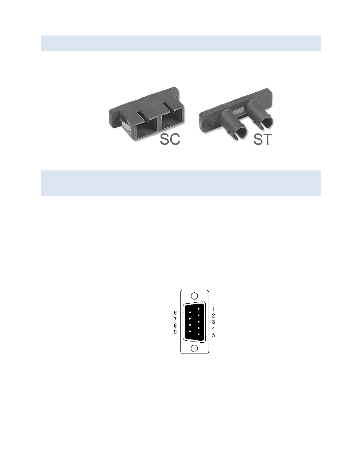
FIBER OPTIC CONNECTORS
Serial server models using fiber Optic network connections use either SC or ST
connectors, depending on the specific model.
SC and ST Fiber Optic Cable Connectors
SERIAL PORT CONNECTORS
VESRxx Serial Servers use three serial port connector configurations, depending on
the model:
VESR901-x serial servers feature one serial port and use a DB-9M connector for RS232 and a five-position removable terminal block for RS-422 and RS-485 connections.
VESR902D-x serial servers feature two serial ports, both using DB-9M connectors for
RS-232, RS-422 and RS-485 connections.
VESR902T-x serial servers feature two serial ports, both using five-position
removable terminal blocks for RS-232, RS-422 and RS-485 connections.
DB-9 Female Serial Port Connector with Pinout

16
Five-Position Pluggable Terminal Blocks
Note: Refer to Appendix D for connection pin-outs.
POWER CONNECTOR
The power connector is a 5.08 mm 2-position pluggable terminal block.
Power Connection

17
MOUNTING HARDWARE
VESR9xx Serial Server modules can be DIN rail mounted. The DIN mounting clip and
spring is included on each module.
DIN Clip on a Serial Server Module
SERIAL SERVER SETUP AND CONNECTIONS
This section describes how to setup and connect VESRxx Serial Servers.
Note: In this section devices to be connected to the serial server’s serial connection are
simply referred to as the “serial device”.
CONNECTING THE POWER SUPPLY
Connect a DC power supply to the power terminals on the top of the serial server.
Polarity of the wires is indicated on the label on the side of the serial server.
Acceptable voltages are between 10 VDC and 48 VDC. The power supply must be
capable of supplying 4 Watts for VESR90x models and 6.0 Watts for VESR92x models.

18
CONNECTING VESR9XX SERIAL SERVERS TO SERIAL DEVICES
VESR9xx Serial Servers can be configured to connect to serial devices using RS-232,
RS-422, RS-485 2-wire and RS-485 4-wire.
RS-232 connections support eight signal lines plus Signal Ground. Signals are single
ended and referenced to Ground. Default communications parameters are 9600, 8,
N, 1 and no flow control implemented.
RS-422 connections support two signal pairs: TDA (-), TDB (+), RDA (-), RDB (+) and
GND. The data lines are differential pairs (A & B) in which the B line is positive
relative to the A line in the idle (mark) state. Ground provides a common mode
reference.
RS-485 connections support 2-wire or 4-wire operation.
When configured for 4-wire operation the connection supports two signal pairs: TDA
(-), TDB (+), RDA (-), RDB (+) and GND. This makes full-duplex operation possible. The
data lines are differential pairs (A & B) in which the B line is positive relative to the A
line in the idle (mark) state. Ground provides a common mode reference.
When configured for 2-wire operation the connection supports one signal pair: Data
A (-) and Data B (+) signal channels using half-duplex operation. The data lines are
differential with the Data B line positive relative to Data A in the idle (mark) state.
Ground provides a common mode reference.
 Loading...