

Page 1

Documentation
KNX OPUS
Gateway
Controlling and visualization of the
OPUS MCU610 System with the EIB/KNX
Order number: E001-H028001
Page 2

Rev.: 04/2012 KNX OPUS Gateway Page 2 of 25
IMPORTANT-READ CAREFULLY:
This b+b End-User License Agreement ("EULA") is a legal agreement between you (either an individual or a single entity) and b+b Automations- und
Steuerungstechnik GmbH, for the software product identified above, which includes computer software and may include associated media, printed
materials, and "online" or electronic documentation ("SOFTWARE PRODUCT"). By installing, copying, or otherwise using the SOFTWARE PRODUCT,
you agree to be bound by the terms of this EULA.
SOFTWARE PRODUCT LICENSE
1. COPYRIGHT TREATIES
The SOFTWARE PRODUCT is protected by copyright laws and international copyright treaties, as well as other intellectual property laws and treaties. The SOFTWARE PRODUCT is licensed, not sold.
2. GRANT OF LICENSE.
This EULA grants you the following rights:
a. Software Product. b+b grants to you as an individual, a personal, nonexclusive license to make and use copies of the SOFTWARE for the sole
purposes of using the SOFTWARE´s functionality.
b. Storage/Network Use. You may also store or install a copy of the SOFTWARE PRODUCT on a storage device, such as a network server, used
only to install or run the SOFTWARE PRODUCT on your other computers over an internal network; however, you must acquire and dedicate a
license for each separate computer on which the SOFTWARE PRODUCT is installed or run from the storage device. A license for the SOFTWARE
PRODUCT may not be shared or used concurrently on different computers.
c. Electronic Documents. Solely with respect to electronic documents included with the SOFTWARE PRODUCT, you may make an unlimited
number of copies (either in hardcopy or electronic form), provided that such copies shall be used only for internal purposes and are not republished or distributed to any third party.
3. DESCRIPTION OF OTHER RIGHTS AND LIMITATIONS.
a. Limitations on Reverse Engineering, Decompilation, and Disassembly. You may not reverse engineer, decompile, or disassemble the SOFTWARE
PRODUCT.
b. Separation of Components. The SOFTWARE PRODUCT is licensed as a single product. Its component parts may not be separated for use on
more than one computer.
c. Changing documentations. You may not make changes to the documentation of the SOFTWARE PRODUCT.
d. Termination. Without prejudice to any other rights, b+b may terminate this EULA if you fail to comply with the terms and conditions of this
EULA. In such event, you must destroy all copies of the SOFTWARE PRODUCT and all of its component parts.
4. COPYRIGHT.
All title and copyrights in and to the SOFTWARE PRODUCT (including but not limited to any images, photographs, animations, video, audio, music,
text, and "applets" incorporated into the SOFTWARE PRODUCT), the accompanying printed materials, and any copies of the SOFTWARE PRODUCT
are owned by b+b or its suppliers. The SOFTWARE PRODUCT is protected by copyright laws and international treaty provisions. Therefore, you must
treat the SOFTWARE PRODUCT like any other copyrighted material except that you may install the SOFTWARE PRODUCT on a single computer
provided you keep the original solely for backup or archival purposes. You may not copy the printed materials accompanying the SOFTWARE
PRODUCT.
5. LIMITED WARRANTY
Except with respect to the REDISTRIBUTABLES, which are provided "as is," without warranty of any kind, b+b warrants that (a) the SOFTWARE
PRODUCT will perform substantially in accordance with the accompanying written materials for a period of ninety (90) days from the date of receipt, and (b) any hardware accompanying the SOFTWARE PRODUCT will be free from defects in materials and workmanship under normal use
and service for a period of one (1) year from the date of receipt.
6. CUSTOMER REMEDIES.
b+b´s entire liability and your exclusive remedy shall be, either (a) return of the price paid, or (b) repair or replacement of the SOFTWARE PRODUCT
or hardware that does not meet b+b Limited Warranty. This Limited Warranty is void if failure of the SOFTWARE PRODUCT or hardware has resulted from accident, abuse, or misapplication.
NO OTHER WARRANTIES: TO THE MAXIMUM EXTENT PERMITTED BY APPLICABLE LAW, b+b DISCLAIMS ALL OTHER WARRANTIES
NO LIABILITY FOR CONSEQUENTIAL DAMAGES: TO THE MAXIMUM EXTENT PERMITTED BY APPLICABLE LAW, IN NO EVENT SHALL b+b OR ITS
SUPPLIERS BE LIABLE FOR ANY SPECIAL, INCIDENTAL, INDIRECT, OR CONSEQUENTIAL DAMAGES WHATSOEVER (INCLUDING, WITHOUT
LIMITATION, DAMAGES FOR LOSS OF BUSINESS PROFITS, BUSINESS INTERRUPTION, LOSS OF BUSINESS INFORMATION, OR ANY OTHER
PECUNIARY LOSS) ARISING OUT OF THE USE OF OR INABILITY TO USE THE SOFTWARE OR HARDWARE PRODUCT, EVEN IF b+b HAS BEEN
ADVISED OF THE POSSIBILITY OF SUCH DAMAGES.
Life support:
These products are not designed for use in life support appliances, devices or systems where malfunction of these products can reasonably be
expected to result in personal injury. b+b customers using or selling these products for use in such applications do so at their own risk and agree to
fully indemnify b+b for any damages resulting from such application.
Copyright 1998 - 2012 b+b Automations- und Steuerungstechnik GmbH. All rights reserved.
Microsoft and Windows are trademarks of Microsoft Corporation.
OPUS is a trademark of OPUS Technologies Ltd.
b+b Automations- und Steuerungstechnik GmbH
©
KNX OPUS GATEWAY.DOC
Page 3

Rev.: 04/2012 KNX OPUS Gateway Page 3 of 25
This handbook describes also functions, which are options.
Only qualified persons are allowed to install our units.
Softwaredesign and Coding: Michael Herbst
Documentation: Michael Herbst
Editor: Steffen Kiene
b+b Automations- und Steuerungstechnik GmbH
Eichenstraße 38a
D-64743 Beerfelden
Tel.: +49 6068 / 478910
Email: support@bb-steuerungstechnik.de
Internet: http://www.bb-steuerungstechnik.de
b+b Automations- und Steuerungstechnik GmbH
©
KNX OPUS GATEWAY.DOC
Page 4

Rev.: 04/2012 KNX OPUS Gateway Page 4 of 25
Table of contents
Highlights KNX OPUS Gateway.....................................................................................................................5
Field of application...........................................................................................................................................5
Scope of delivery...............................................................................................................................................5
Introduction.......................................................................................................................................................6
Technical data ...................................................................................................................................................7
Connection overview.......................................................................................................................................8
Display and control elements.........................................................................................................................9
Installation instruction.................................................................................................................................. 10
Parametrisation with the b+b Terminal software ................................................................................... 11
Automatic USB driver installation.................................................................................................11
Manual USB driver installation......................................................................................................11
Establish a connection with the KNX OPUS Gateway ................................................................15
Configure gateway specific settings.............................................................................................16
Configure channel settings ...........................................................................................................17
EIB/KNX
OPUS
Transfer parametrisation to the KNX OPUS Gateway.................................................................21
Æ
OPUS Transmission ....................................................................................................18
Æ
EIB/KNX Transmission ....................................................................................................20
Functional description .................................................................................................................................. 23
Parametrisation phase ...................................................................................................................23
Parametrisation check....................................................................................................................23
ASCII command interface............................................................................................................................. 24
ASCII commands overview ............................................................................................................24
b+b Automations- und Steuerungstechnik GmbH
©
KNX OPUS GATEWAY.DOC
Page 5

Rev.: 04/2012 KNX OPUS Gateway Page 5 of 25
Highlights KNX OPUS Gateway
• Integrated EIB/KNX – bus coupling unit with two wire EIB/KNX connector
• Easy parametrisation with the b+b Terminal software over USB connection
• Each KNX OPUS Gateway can handle up to 200 configuration channels
• Rail mounted device (6TE = 105mm) with integrated 85V – 260V wide range power supply
Field of application
• Simple integration of OPUS MCU610 controller in the EIB/KNX bussystem
• Visualization of OPUS states (e.g. “Input Select”, “Volume”, …) in the EIB/KNX bussystem
• Controlling OPUS instructions (e.g. “Volume Up”, “Input Select”, …) from the EIB/KNX bussystem
Scope of delivery
• KNX OPUS Gateway
• USB cable
• b+b Terminal software for parametrisation
• Documentation
b+b Automations- und Steuerungstechnik GmbH
©
KNX OPUS GATEWAY.DOC
Page 6

Rev.: 04/2012 KNX OPUS Gateway Page 6 of 25
Introduction
The KNX OPUS Gateway allows the communication between the EIB/KNX bussystem and the MCU610
controller from OPUS. The Gateway establishes a bidirectional communication, which means you can
transmit data from the EIB/KNX bussystem to the OPUS system and you can also transmit data from the
OPUS system to the EIB/KNX bussystem.
You can use the gateway on the one hand for visualization of OPUS MCU610 states like e.g. “Volume”,
“Balance”, … in the EIB/KNX system. On the other hand it is possible to execute OPUS instructions from
the EIB/KNX bussystem with an EIB/KNX switch like e.g. “Input Select”, “Volume Up”/”Volume Down”,
... instructions.
The parametrisation of the KNX OPUS Gateway is performed through the integrated USB interface in
conjunction with the b+b Terminal software.
The hardware of the KNX OPUS Gateway consists of a 6TE (= 105mm) DIN rail mounting enclosure
with integrated 85V – 260V power unit and connectors for OPUS MCU610 and EIB/KNX. The device is
maintenance-free without fan or any other wear parts.
Figure 1: Field of application for the “KNX OPUS Gateway”
b+b Automations- und Steuerungstechnik GmbH
©
KNX OPUS GATEWAY.DOC
Page 7

Rev.: 04/2012 KNX OPUS Gateway Page 7 of 25
Technical data
External dimensions
(W x H x D)
105mm x 90mm x 59mm
Casing DIN rail mounted, plastic, 6TE, lightgrey (RAL 7035)
Weight 0,3 kg
Power supply
85V – 260V AC, 50Hz – 60Hz, connection over screw terminals
(max. 2 x 2,5mm² solid wire / max. 2 x 1,5mm² flexible wire)
Power consumption 30mA
Temperature range 0°C … +50°C (in operation)
0°C … +70°C (storage)
Degree of protection IP20
Interfaces
1.) RS-232 connection to OPUS MCU610 controller over D-Sub 9 pole (female) connector via a 1:1 cable (male – female)
2.) USB as service interface (for parametrisation) over
Mini USB connector Type B
Virtual COM port
Baudrate: 57600 Baud
3.) EIB/KNX connection via standard EIB/KNX connector
Table 1: Technical data
b+b Automations- und Steuerungstechnik GmbH
©
KNX OPUS GATEWAY.DOC
Page 8
Rev.: 04/2012 KNX OPUS Gateway Page 8 of 25
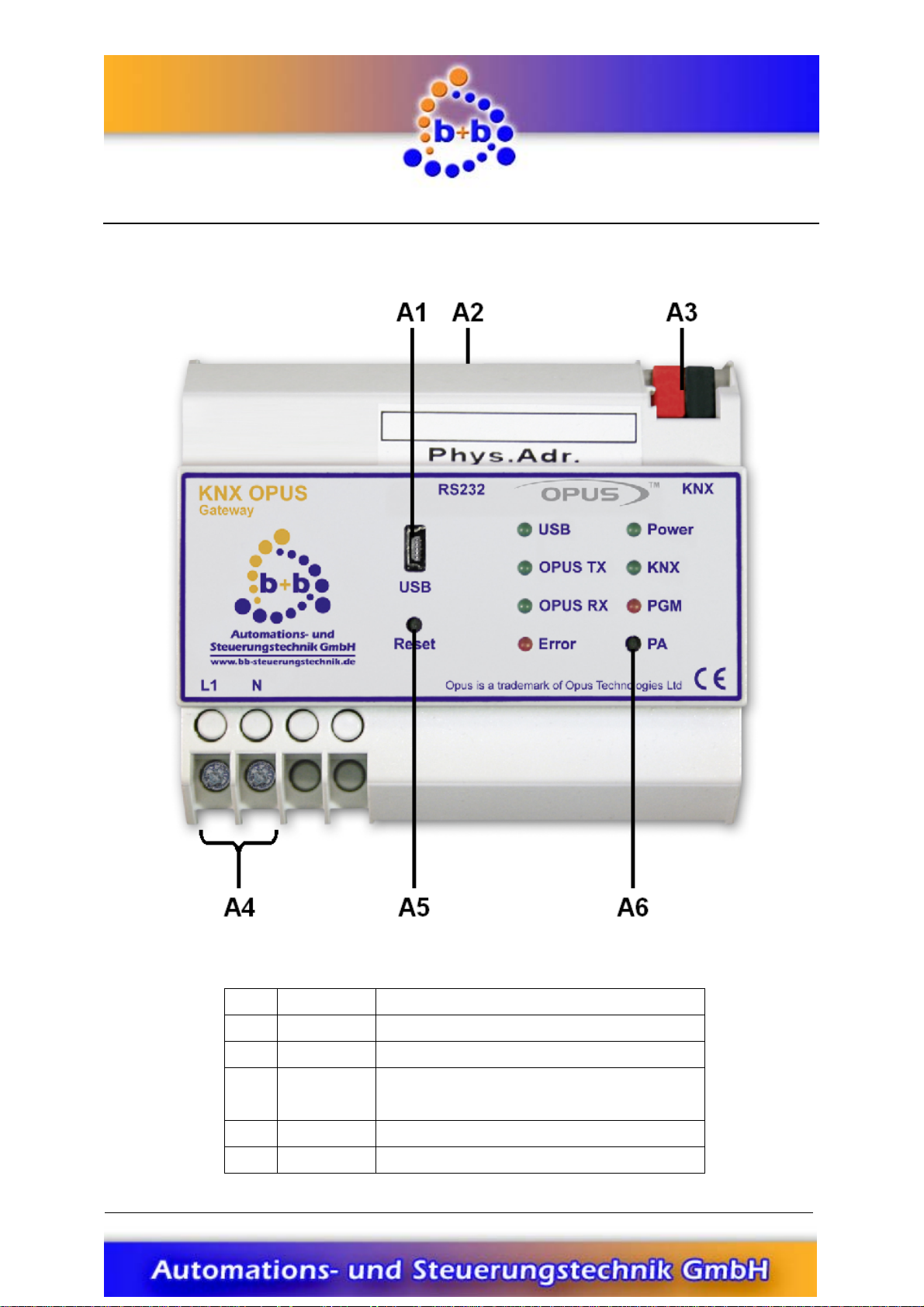
Connection overview
Figure 2: Connection overview KNX OPUS Gateway
A1
A2
A3
A4
A5
A6
b+b Automations- und Steuerungstechnik GmbH
©
USB
RS232
KNX
L1 / N
RESET
PA
Table 2: Connection overview KNX OPUS Gateway
USB connector (Mini USB Typ B)
Serial connection (RS-232) to OPUS MCU610
EIB/KNX connector
Power supply 85V – 260V AC
L1: Phase conductor N: Neutral conductor
Reset button
Programming button
KNX OPUS GATEWAY.DOC
Page 9

Rev.: 04/2012 KNX OPUS Gateway Page 9 of 25
Display and control elements
Figure 3: Detail view display and control elements
Button Function
Keypress long (>= 3 seconds):
Reset
PA
LED Function
USB
OPUS TX
OPUS RX
Error
Power
KNX
PGM
The KNX OPUS Gateway reboots.
Note: The long keypress recognition is signalled by illuminating the LEDs
OPUS
TX, OPUS RX, Error, Power, KNX and PGM.
Keypress short (< 3 seconds):
The KNX OPUS Gateway switches to programming mode for EIB/KNX physical address setup. The programming mode is visualised with an illuminated LED
You can leave the programming mode by short pressing the
LED flashing:
A data transmission between the PC and the KNX OPUS Gateway over the USB interface is in progress.
LED flashing:
The KNX OPUS Gateway sends a telegram to the OPUS system.
LED flashing:
The KNX OPUS Gateway receives a telegram from the OPUS system.
LED flashing (frequency: ~ 1Hz):
The KNX OPUS Gateway has detected an EIB/KNX busvoltage breakdown. The
EIB/KNX bus voltage is checked cyclic every 30 seconds.
LED illuminated:
Power supply OK
LED flashing:
The KNX OPUS Gateway sends or receives an EIB/KNX telegram.
LED illuminated:
The KNX OPUS Gateway is currently in programming mode, waiting for an EIB/KNX
physical address.
LED flashing (frequency ~1Hz):
The KNX OPUS Gateway is running in normal operating mode.
Table 3: Display and control elements
PA Button again.
PGM.
b+b Automations- und Steuerungstechnik GmbH
©
KNX OPUS GATEWAY.DOC
Page 10

Rev.: 04/2012 KNX OPUS Gateway Page 10 of 25
Installation instruction
• Mount the KNX OPUS Gateway on a standard DIN rail.
• Connect the KNX OPUS Gateway to the EIB/KNX bussystem with a standard bus connector.
• Connect your OPUS MCU610 controller via the RS-232 Port 3 to the KNX OPUS Gateway. Use a
D-Sub 9 pole serial 1:1 cable (male - female) for this connection.
• Connect the power supply (85V – 260V AC) to your KNX OPUS Gateway.
• If everything is connected properly you can switch on the power supply.
After installing the KNX OPUS Gateway you have to configure it (see section „Parametrisation with
the b+b Terminal software“).
b+b Automations- und Steuerungstechnik GmbH
©
KNX OPUS GATEWAY.DOC
Page 11

Rev.: 04/2012 KNX OPUS Gateway Page 11 of 25
Parametrisation with the b+b Terminal software
Before using the KNX OPUS Gateway you first have to setup all OPUS instructions you want to map to
EIB/KNX group addresses. The parametrisation of the gateway is handled via a dialog in the b+b Terminal software and can be transferred to the KNX OPUS Gateway over the USB interface.
Note: The parametrisation dialog is available in the b+b Terminal software since version 1.32. If you
have already installed our b+b Terminal software on your PC please ensure that you have at least version 1.32 (see menu item „
our b+b Terminal software on the provided EIB Tools CD or on our homepage under „
dates and Downloads
Before you can parametrise the KNX OPUS Gateway you first have to install the driver for the USB interface. The driver can be found on the provided EIB Tools CD in the directory „
“. For installing the driver please proceed with the following steps:
GW\
?\Info about b+bTerminal…
“.
Automatic USB driver installation
There’s a setup package available which automatically selects and installs the correct driver required by
your operating system. To start the setup procedure doubleclick the file CDM20814_Setup.exe. in the
directory „
for a short period of time and automatically closes. After installing the USB driver you can connect the
KNX OPUS Gateway with your PC. The KNX OPUS Gateway is recognized and the needed drivers are
loaded automatically.
…\Support\USB KNX OPUS GW\
“ on the EIB Tools CD. A command prompt window opens
“) installed. You can find the current version of
Support \ Up-
…\Support\USB KNX OPUS
Manual USB driver installation
If you have problems with installing the automatic setup program, you can also install the USB drivers
manually. There’s a ZIP archive named CDM20814 WHQL Certified.zip in the directory
…\Support\USB KNX OPUS GW\
„
content into any directory. Proceed with the following steps for manual driver installation:
Ensure that the KNX OPUS Gateway is connected to the power supply (LED
connect it to your PC with the provided USB cable. You should see the following pop up message in
your taskbar:
After this pop up message the „
not this time
“ and push the „
“ on the EIB Tools CD. Copy this file to your harddisk and extract the
Power illuminated) and
Figure 4: “Found New Hardware“ pop up
Found New Hardware Wizard
Next >
“ button (see Figure 5).
“ should appear. Select the option „
No,
b+b Automations- und Steuerungstechnik GmbH
©
KNX OPUS GATEWAY.DOC
Page 12

Rev.: 04/2012 KNX OPUS Gateway Page 12 of 25
Figure 5: “Found New Hardware Wizard” step 1
In the second step of the Hardware Wizard select the option „
vanced)
“ and click again on the „
Next >
“ button.
Install from a list or specific location (Ad-
Figure 6: “Found New Hardware Wizard” step 2
In the last step of the Hardware Wizard select the directory on your harddisk in which you have ex-
Next >
tracted the ZIP archive before (e.g. “D:\Support\FTDI\”) and push the button „
“.
b+b Automations- und Steuerungstechnik GmbH
©
KNX OPUS GATEWAY.DOC
Page 13

Rev.: 04/2012 KNX OPUS Gateway Page 13 of 25
Figure 7: “Found New Hardware Wizard” step 3
The Hardware Wizard signals the successful driver installation in the last dialog. Finish the „
Hardware Wizard
“ by pushing the „
After installing the driver for the „
driver for the „
USB Serial Port
Finish
“ button.
Figure 8: “Found New Hardware Wizard” successful
USB Serial Converter
“, the Found New Hardware Wizard will ask for a
“. Please repeat the steps of the installation process above to install this
driver. The Hardware Wizard again signals the successful driver installation in the last dialog:
Found New
b+b Automations- und Steuerungstechnik GmbH
©
KNX OPUS GATEWAY.DOC
Page 14

Rev.: 04/2012 KNX OPUS Gateway Page 14 of 25
Figure 9: “Found New Hardware Wizard” successful
Finish the Found New Hardware Wizard by pushing the „
Finish
“ button.
b+b Automations- und Steuerungstechnik GmbH
©
KNX OPUS GATEWAY.DOC
Page 15

Rev.: 04/2012 KNX OPUS Gateway Page 15 of 25
Establish a connection with the KNX OPUS Gateway
Note: The b+b Terminal software beginning from version 1.32 gives you the opportunity to automati-
cally recognize the virtual COM port of the connected KNX OPUS Gateway. Open the menuitem „
tings Æ Communication port / generic settings
OPUS GW
Protocol. Close the window with the „
COM port of your connected KNX OPUS GW manually. Please proceed as follows:
To establish a connection with your KNX OPUS Gateway you need to know the virtual COM port number under which the KNX OPUS Gateway was installed. To find out this COM port number you have to
open the „
the menu entry „
ager
You can recognize (and also change) the virtual COM port of your KNX OPUS Gateway behind the
entry „
“ in the combobox „
Device Manger
Manage
“ entry in the left tree view and click on the „
USB Serial Port
“.
Com port
” by a right click on the „
”. The „
“. Choose Baudrate 57600, 8 Data Bits, 1 Stop Bit, No Parity, No
OK
“ button. In all versions < 1.32 you need to setup the virtual
Computer Management
“. Choose „
My Computer
Ports (COM & LPT)
Serial
“ as connection type and „
“ symbol on your desktop and choose
“ window is opened. Select the „
“ entry.
Device Man-
Set-
b+b KNX
Figure 10: Device Manager
b+b Automations- und Steuerungstechnik GmbH
©
KNX OPUS GATEWAY.DOC
Page 16

Rev.: 04/2012 KNX OPUS Gateway Page 16 of 25
With this information you can now start the b+b Terminal software. Choose the menu entry „
Æ Communication port / generic settings
“. The window „
Port settings…
“ appears. In this dialog you can
Settings
select the virtual COM port of your KNX OPUS Gateway and the following settings:
Figure 11: b+b Terminal menu item „
Settings Æ Communication port / generic settings
“
After you’ve setup the connection, close the window by clicking on the „OK“ button. To start the communication with your KNX OPUS Gateway you have to click on the green arrow button in the toolbar.
To test the connection you can send a „
?v“ command to your gateway. The KNX OPUS Gateway
should respond with the following text (firmware version and serial number may differ):
b+b KNX OPUS Gateway V0.90 (compiled Nov 3 2011) SN: 12345678
Configure gateway specific settings
To configure your KNX OPUS Gateways select the menu item „
in the b+b Terminal software. The parametrisation main window appears (see Figure 12).
Settings Æ b+b KNX OPUS Gateway …
“
b+b Automations- und Steuerungstechnik GmbH
©
KNX OPUS GATEWAY.DOC
Page 17

Rev.: 04/2012 KNX OPUS Gateway Page 17 of 25
Figure 12: KNX OPUS Gateway parametrisation dialog
In the top section of the dialog window you can setup the gateway specific settings. Enter the desired
EIB/KNX physical address for your KNX OPUS Gateway in the field „
Physical address
”.
In the field „
Alive GA
address a „1“ is written cyclic (see description of the field „
“ you have the opportunity to setup an EIB/KNX group address. On this group
Send Interval
“) if the KNX OPUS Gateway is
alive.
The time interval (in minutes) in which the above EIB/KNX group address is written cyclic can be specified in the field „
Send Interval
Activating the checkbox „
“.
Auto ACK
“ activates the Auto ACK mode in the KNX OPUS Gateway. In the
Auto ACK mode the KNX OPUS Gateway automatically acknowledges all EIB/KNX group address telegrams, which can reduce the bus load on your EIB/KNX bussystem.
Configure channel settings
After setting up the Gateway specific data you can now start to configure your OPUS instruction to
EIB/KNX group address mappings. It is possible to setup up to 200 different channels per KNX OPUS
Gateway, which means you can map up to 200 different OPUS instructions to EIB/KNX group addresses.
To setup a new channel click on the button „
occurs (see Figure 13).
New channel…
“. The „
Channel settings…
“ dialog window
b+b Automations- und Steuerungstechnik GmbH
©
KNX OPUS GATEWAY.DOC
Page 18

Rev.: 04/2012 KNX OPUS Gateway Page 18 of 25
Figure 13: Adding a new channel
In this dialog you have to enter the channel specific settings. First choose the OPUS instruction you
want to map to an EIB/KNX group address in the field „
OPUS Instruction
“. Depending on your OPUS
instruction choice different fields on the dialog are now enabled or disabled.
Please choose the OPUS address (MCU and Zone) in the fields „
OPUS MCU
“ and „
OPUS Zone
“ for
which you want to configure your channel.
Next there are two sections for configuration (maybe one of them is disabled, depending on the OPUS
instructions you’ve chosen):
(1.) EIB/KNX Æ OPUS Transmission (Direction ‘S’)
(2.) OPUS Æ EIB/KNX Transmission (Direction ‘U’/Direction ‘T’)
EIB/KNX Æ OPUS Transmission
In the middle of the window (see Figure 14) you can map EIB/KNX group addresses to the OPUS instruction for the transmission direction EIB/KNX Æ OPUS. This means if you write data to the EIB/KNX
group address entered in the field „
KNX Groupaddress
an OPUS instruction with direction “S”.
b+b Automations- und Steuerungstechnik GmbH
©
“ this data is transmitted to the OPUS system as
KNX OPUS GATEWAY.DOC
Page 19

Rev.: 04/2012 KNX OPUS Gateway Page 19 of 25
First enter an EIB/KNX Groupaddress in the field „
KNX Groupaddress
“. Depending on the OPUS instruction you’ve chosen you can now choose a data format, for the EIB/KNX groupaddress you’ve entered
before, in the field „
KNX Data Format
“. Sometimes this field is also disabled and a value is entered which
you can not change. This is the case for all OPUS instructions which allow only 1 Bit (0 or 1) data value.
Figure 14: “EIB/KNX Æ OPUS Transmission” section
The OPUS instruction “’01’ – Input Select” e.g. is an instruction which allows to choose the KNX data
format. If you choose “8 Bit Unsigned” in the combobox „
KNX Data Format
“ (see figure 14) you can
write a 8 Bit data value to your parametrised EIB/KNX group address, which is then directly used as the
data value in the OPUS instruction telegram send to your OPUS system. That means, if you write e.g.
the data value “5” to EIB/KNX group address “1/0/1”, the KNX OPUS Gateway transmits the OPUS instruction “#11S0105!” to your OPUS system.
If you choose the “1 Bit Binary” entry in the combobox „
KNX Data Format
“ you can use e.g. an EIB/KNX
switch to control the OPUS instruction “Input Select”:
If you select the option „
Fixed Data Value”
(see figure 15) you can save a predefined value in the KNX
OPUS Gateway which will be used for the data value in your OPUS instruction telegram whenever you
write a “0” or “1” (depending on your choice in the field „
Trigger Level”
) to your parametrised EIB/KNX
group address.
With the option „
Data Value Range”
you can setup a predefined lower and upper limit for the data
value in your OPUS instruction. Whenever you send a “0” or “1” (depending on your choice in the field
Trigger Level”
„
) to the parametrised EIB/KNX group address the KNX OPUS Gateway walks cyclic
through your defined range and sends OPUS instructions with the current range value as data value to
the OPUS system. (In case you’ve chosen the OPUS instruction “Input Select” (see figure 15) you can
also select all single values through which the gateway should cycle.)
In the combobox „
Trigger Level”
you can setup if the KNX OPUS Gateway should react on the value “0”
or on the value “1” written to your parametrised EIB/KNX group address.
b+b Automations- und Steuerungstechnik GmbH
©
KNX OPUS GATEWAY.DOC
Page 20

Rev.: 04/2012 KNX OPUS Gateway Page 20 of 25
Figure 15: Data Value Options for OPUS Instruction “Input Select”
In the option group below the Data Value Options you can choose when the KNX OPUS Gateway
should transmit data from the EIB/KNX bussystem to the OPUS system.
If you choose the option „
this channel. The option „
Never send to OPUS
Always send to OPUS
“, you can disable the transmission EIB/KNX Æ OPUS for
“ tells the gateway that a WriteValue to the parametrised EIB/KNX group address should always send an OPUS instruction with the direction ‘S’ to the OPUS
system. With the option „
Send to OPUS only on data value change
“ the gateway checks on every ValueWrite which value was received before on the parametrised EIB/KNX group address. Only if these
two values differ an OPUS instruction with direction ‘S’ is transmitted to the OPUS system. (This means if
you write 3 times the value “2” on your EIB/KNX group address only 1 OPUS instruction telegram with
direction ‘S’ will be generated from the KNX OPUS Gateway.)
OPUS Æ EIB/KNX Transmission
Figure 16: “OPUS Æ EIB/KNX Transmission” section
b+b Automations- und Steuerungstechnik GmbH
©
KNX OPUS GATEWAY.DOC
Page 21

Rev.: 04/2012 KNX OPUS Gateway Page 21 of 25
On the bottom of the window (see Figure 16) you can map EIB/KNX group addresses to the OPUS
instruction you’ve chosen before for transmission direction OPUS Æ EIB/KNX. These mappings can be
used for sending update instructions (Direction ‘U’) or text instructions (Direction ‘T’) from the OPUS
system to the EIB/KNX bussystem. These values can e.g. be used for visualization purposes.
First you enter a EIB/KNX Groupaddress in the field „
instruction you’ve chosen you can now choose a data format, for the EIB/KNX groupaddress you’ve
entered before, in the field „
In the option group below the KNX Data Format you can choose when the KNX OPUS Gateway should
transmit data from the OPUS system to the EIB/KNX bussystem.
If you choose the option „
for this channel. The option „
instruction should always execute a ValueWrite on the EIB/KNX bussystem for the parametrised
EIB/KNX group address. With the option „
checks on every ‘U’ or ‘T’ direction OPUS instruction which value was received before from the OPUS
system. Only if these two values differ an EIB/KNX ValueWrite with the reveived data value is transmitted to the EIB/KNX bussystem. (This means if you send 3 times the OPUS instruction “#11S0105!” you
will see only 1 EIB/KNX ValueWrite to EIB/KNX group address “2/0/1” with the data value “5” on your
EIB/KNX bussystem.)
Repeat the described steps above until you have setup all your needed channels (max. 200 channel
configurations are possible per KNX OPUS Gateway).
KNX Data Format
Never send to EIB/KNX
Always send to EIB/KNX
“.
Send to EIB/KNX only on data value change
KNX Groupaddress
“, you can disable the transmission OPUS Æ EIB/KNX
“ tells the gateway that a an direction ‘U’ or ‘T’
“. Depending on the OPUS
“ the gateway
Transfer parametrisation to the KNX OPUS Gateway
With the button „
change your parametrisation you can use the „
After you have finished your parametrisation you can transfer the parametrisation to the KNX OPUS
Gateway by clicking the button „
Save to file…
“ you can save your parametrisation in a „
Transfer to GW
Load from file…
“.
“ button to reload your parametrisation.
.KOG
“ file. If you want to
Note: If you want to transfer the parametrisation to your KNX OPUS Gateway it is necessary to establish
a connection to the gateway before opening the parametrisation dialog. You can establish the connec-
Start
tion with the „
OPUS Gateway the button „
tion transfer is impossible.
Important: If you transfer a new parametrisation to your KNX OPUS Gateway an existing parametrisation in the device is overwritten! With the button „
tion of your KNX OPUS Gateway at any time and save it as a „
b+b Automations- und Steuerungstechnik GmbH
©
“ button (green arrow in the toolbar). If there’s no connection existing to the KNX
Transfer to GW
“ and „
Read from GW
Read from GW
.KOG
“ are deactivated and a parametrisa-
“ you can read out the parametrisa-
“ file.
KNX OPUS GATEWAY.DOC
Page 22

Rev.: 04/2012 KNX OPUS Gateway Page 22 of 25
Figure 20: Parametrisation dialog b+b KNX OPUS Gateway (Online)
b+b Automations- und Steuerungstechnik GmbH
©
KNX OPUS GATEWAY.DOC
Page 23

Rev.: 04/2012 KNX OPUS Gateway Page 23 of 25
Functional description
After the KNX OPUS Gateway was installed and parametrised it is ready for operation.
The KNX OPUS Gateway has seven light emitting diodes (LEDs) on its top to visualise the current device
status, data transmission and errors to the user. The meaning of these LEDs was described in the sec-
Display and control elements
tion „
in different situations is described:
Parametrisation phase
If the KNX OPUS Gateway is running in parametrisation mode the LEDs Error, KNX and PGM are
blinking altogether (Frequency ~ 1Hz).
Parametrisation check
After the system startup the KNX OPUS Gateway checks it’s parametrisation. If the Gateway has no
parametrisation or a the current parametrisation is corrupted the LEDs
blinking in common. In this case the KNX OPUS Gateway needs to be parametrised for operation (see
section „
Parametrisation with the b+b Terminal software
“. In the following section the behaviour of the KNX OPUS Gateway
Error, KNX and PGM are
“).
After the parametrisation check succedded the KNX OPUS Gateway sends the text „
Gateway started
The KNX OPUS Gateway is now runninig in normal operating mode, which is signaled by a cyclic flashing (frequency: ~ 1Hz) of the LED
“ via the USB interface.
PGM.
b+b KNX OPUS
b+b Automations- und Steuerungstechnik GmbH
©
KNX OPUS GATEWAY.DOC
Page 24

Rev.: 04/2012 KNX OPUS Gateway Page 24 of 25
ASCII command interface
The KNX OPUS Gateway offers an easy to use ASCII command interface for diagnosis purposes. The
user can connect to the KNX OPUS Gateway with any terminal program over the virtual COM port and
transmit ASCII commands to the gateway.
The communication between PC and KNX OPUS Gateway is textbased. The “carriage return“ character
(0x0D hexadecimal) signals the end of an ASCII command and is abbreviated with
ing text. ASCII commands from the PC are case insensitive.
ASCII commands overview
Table 5 gives an overview of all ASCII command which are supported by the KNX OPUS Gateway.
<CR> in the follow-
Note: You can also view a short overview of all ASCII commands if you send the command „
to the KNX OPUS Gateway.
? | ?H
?V
?P
?G
DISPINSTS
DISPINST=<INST>
DISPALLCH
DISPCH=<CH>
DISPCHL=<CH>
Show ASCII command overview
Show information about serial number and firmware version ot the KNX
OPUS Gateway
Show physical address of the KNX OPUS Gateway
Overview KNX OPUS Gateway settings
Show all parametrised OPUS Instructions
Show parametrisation of OPUS Instruction <INST> (<INST> = 1 … 85)
Show all available channel parametrisations
Show parametrisation of channel <CH> (<CH> = 1 … 200)
Show parametrisation of channel <CH> and all linked channels with the
same OPUS Instruction (
<CH> = 1 … 200)
?“ or „?H“
DISPALLGAE
DISPGA=<GA>
DISP1STGAE
ERASE!
Show a list of all used EIB/KNX group addresses
Show settings of EIB/KNX group address <GA> (z.B. <GA> = 0/0/1)
Show index of first EIB/KNX group address entry
Erase KNX OPUS Gateway parametrisation
OA{+|-} KNX Auto Acknowledge mode: OA+: enabled OA-: disabled
OL
b+b Automations- und Steuerungstechnik GmbH
©
Language of dialog texts: German
KNX OPUS GATEWAY.DOC
Page 25

Rev.: 04/2012 KNX OPUS Gateway Page 25 of 25
OLE
Language of dialog texts: English
PA:<PA>
RESET
Set physical address <PA> (e.g. <PA> = 1.1.254)
Restart KNX OPUS Gateway
Table 5: Overview ASCII commands
b+b Automations- und Steuerungstechnik GmbH
©
KNX OPUS GATEWAY.DOC
 Loading...