

Page 1
Documentation
KNX-GSM
Gateway
EIB/KNX remote control and
alarming with a mobile phone
Order number: E001-H031007
Page 2

Rev: 03/2009
KNX-GSM Gateway
Page 2 of 19
IMPORTANT-READ CAREFULLY:
This b+b End-User License Agreement ("EULA") is a legal agreement between you (either an individual or a single entity) and b+b Automations- und Steuerungstechnik GmbH, for the software product identified above, which includes computer software and may include associated media, printed materials, and "online" or electronic documentation ("SOFTWARE PRODUCT"). By installing, copying, or otherwise using the SOFTWARE PRODUCT, you agree to be bound by the terms of this EULA.
SOFTWARE PRODUCT LICENSE
1. COPYRIGHT TREATIES
The SOFTWARE PRODUCT is protected by copyright laws and international copyright treaties, as well as other intellectual property laws
and treaties. The SOFTWARE PRODUCT is licensed, not sold.
2. GRANT OF LICENSE.
This EULA grants you the following rights:
a. Software Product. b+b grants to you as an individual,
a personal, nonexclusive license to make and use copies of the
SOFTWARE for the sole purposes of using the SOFTWARE´s
functionality.
b. Storage/Network Use. You may also store or install a copy of the
SOFTWARE PRODUCT on a storage device, such as a network server, used
only to install or run the SOFTWARE PRODUCT on your other computers
over an internal network; however, you must acquire and dedicate a
license for each separate computer on which the SOFTWARE PRODUCT is
installed or run from the storage device. A license for the SOFTWARE
PRODUCT may not be shared or used concurrently on different computers.
c. Electronic Documents. Solely with respect to electronic documents
included with the SOFTWARE PRODUCT, you may make an unlimited number
of copies (either in hardcopy or electronic form), provided that such
copies shall be used only for internal purposes and are not
republished or distributed to any third party.
3. DESCRIPTION OF OTHER RIGHTS AND LIMITATIONS.
a. Limitations on Reverse Engineering, Decompilation, and Disassembly.
You may not reverse engineer, decompile, or disassemble the SOFTWARE
PRODUCT.
b. Separation of Components. The SOFTWARE PRODUCT is licensed as a
single product. Its component parts may not be separated for use on
more than one computer.
c. Changing documentations. You may not make changes to the documentation
of the SOFTWARE PRODUCT.
d. Termination. Without prejudice to any other rights, b+b
may terminate this EULA if you fail to comply with the terms and
conditions of this EULA. In such event, you must destroy all copies
of the SOFTWARE PRODUCT and all of its component parts.
4. COPYRIGHT.
All title and copyrights in and to the SOFTWARE PRODUCT (including but not
limited to any images, photographs, animations, video, audio, music, text,
and "applets" incorporated into the SOFTWARE PRODUCT), the accompanying printed
materials, and any copies of the SOFTWARE PRODUCT are owned by b+b
or its suppliers. The SOFTWARE PRODUCT is protected by copyright laws and
international treaty provisions. Therefore, you must treat the SOFTWARE PRODUCT
like any other copyrighted material except that you may install the SOFTWARE
PRODUCT on a single computer provided you keep the original solely for backup
or archival purposes. You may not copy the printed materials accompanying the
SOFTWARE PRODUCT.
5. LIMITED WARRANTY
Except with respect to the REDISTRIBUTABLES, which are provided "as is,"
without warranty of any kind, b+b warrants that (a) the
SOFTWARE PRODUCT will perform substantially in accordance with the accompanying
written materials for a period of ninety (90) days from the date of receipt,
and (b) any hardware accompanying the SOFTWARE PRODUCT will be free from defects
in materials and workmanship under normal use and service for a period of
one (1) year from the date of receipt.
6. CUSTOMER REMEDIES.
b+b´s entire liability and your exclusive remedy shall be, either
b+b Automations- und Steuerungstechnik GmbH
©
KNX-GSM GATEWAY.DOC
Page 3

Rev: 03/2009
KNX-GSM Gateway
(a) return of the price paid, or (b) repair or replacement of the SOFTWARE
PRODUCT or hardware that does not meet b+b Limited Warranty.
This Limited Warranty is void if failure of the SOFTWARE PRODUCT or hardware
has resulted from accident, abuse, or misapplication.
NO OTHER WARRANTIES: TO THE MAXIMUM EXTENT PERMITTED BY APPLICABLE
LAW, b+b DISCLAIMS ALL OTHER WARRANTIES
NO LIABILITY FOR CONSEQUENTIAL DAMAGES: TO THE MAXIMUM EXTENT
PERMITTED BY APPLICABLE LAW, IN NO EVENT SHALL b+b
OR ITS SUPPLIERS BE LIABLE FOR ANY SPECIAL, INCIDENTAL,
INDIRECT, OR CONSEQUENTIAL DAMAGES WHATSOEVER (INCLUDING,
WITHOUT LIMITATION, DAMAGES FOR LOSS OF BUSINESS PROFITS,
BUSINESS INTERRUPTION, LOSS OF BUSINESS INFORMATION, OR ANY
OTHER PECUNIARY LOSS) ARISING OUT OF THE USE OF OR INABILITY
TO USE THE SOFTWARE OR HARDWARE PRODUCT, EVEN IF b+b
HAS BEEN ADVISED OF THE POSSIBILITY OF SUCH DAMAGES.
Life support:
These products are not designed for use in life support appliances, devices or
systems where malfunction of these products can reasonably be expected to result
in personal injury. B+b customers using or selling these products
for use in such applications do so at their own risk and agree to fully
indemnify b+b for any damages resulting from such application.
Copyright 1998 - 2009 b+b Automations- und Steuerungstechnik GmbH. All rights reserved.
Microsoft and Windows are trademarks of Microsoft Corporation.
This handbook describes also functions, which are options.
Only qualified persons are allowed to install our units.
Softwaredesign und Coding: Volker Knapp, Peter Bernert, Michael Herbst
Documentation: Volker Knapp, Peter Bernert, Michael Herbst
Editor: Steffen Kiene
b+b Automations- und Steuerungstechnik GmbH
Eichenstraße 38a
D-64743 Beerfelden
Tel.: +49 6068 / 478910
Email: support@bb-steuerungstechnik.de
Internet: http://bb-steuerungstechnik.de
Page 3 of 19
b+b Automations- und Steuerungstechnik GmbH
©
KNX-GSM GATEWAY.DOC
Page 4

Rev: 03/2009
KNX-GSM Gateway
Page 4 of 19
Table of Contents
Highlights KNX-GSM Gateway..............................................................................................................5
Fields of application............................................................................................................................... 5
Contents of delivery...............................................................................................................................5
Introduction............................................................................................................................................6
Technical data .......................................................................................................................................6
General ........................................................................................................................................................6
GSM Standards ..........................................................................................................................................6
SIM cards.....................................................................................................................................................7
GSM antenna..............................................................................................................................................7
Overview................................................................................................................................................8
Installation instruction ............................................................................................................................9
Functions .............................................................................................................................................10
LED description ........................................................................................................................................10
Parameterisation phase...........................................................................................................................10
System startup phase ..............................................................................................................................11
Test mode..................................................................................................................................................12
Alarm input ................................................................................................................................................12
Configuration with the EIBDoktor software..........................................................................................13
Transfering the configuration...............................................................................................................19
b+b Automations- und Steuerungstechnik GmbH
©
KNX-GSM GATEWAY.DOC
Page 5

Rev: 03/2009
KNX-GSM Gateway
Page 5 of 19
Highlights KNX-GSM Gateway
• Bi-directional EIB/KNX ÅÆ GSM communication via short messages (SMS)
• Quadband GSM support for worldwide use
• Only additional SIM card required, no other hardware is needed
• Integrated EIB/KNX – bus coupling unit with two wire EIB/KNX connector
• Integrated real time clock
• Writing values to all 32767 groupaddresses by SMS
• Up to 100 event messages can be set to up to 8 receivers
• A receiver can be: (*: network provider dependent)
¾ mobile phone
¾ telephone *
¾ fax *
¾ e-mail address *
• Eight event time ranges are possible, time synchronisation via EIB-DCF
• Access control for protection against unauthorized access to your EIB/KNX – installation:
¾ phone number filter
¾ password protection for commands via SMS
¾ groupaddress filter
• Alarm input
• Automatic log in to the GSM network after power failure
• Alarming on sabotage, bus voltage loss, bus voltage return
• Routine event message every X hour for monitoring the gateway („Alive – SMS“)
• Event message when starting the gateway („BootUp – SMS“)
• Easy configuration using the EIBDoktor software
Fields of application
• Remote control your EIB/KNX – installation via mobile phone over GSM network
• Monitor your EIB/KNX – installation via mobile phone over GSM network
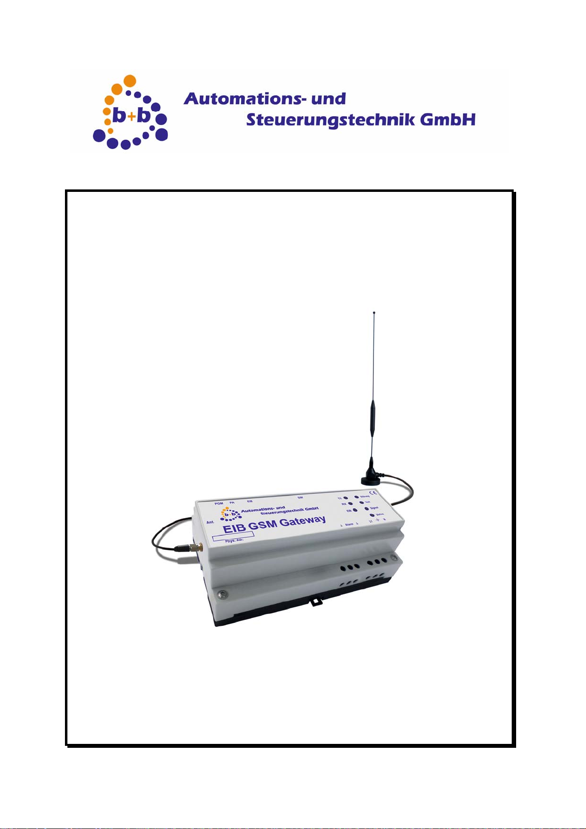
Contents of delivery
• KNX-GSM Gateway
• Dualband GSM antenna (supports GSM frequency bands 900MHz and 1800MHz)
• EIBDoktor software for configuration
• Documentation
b+b Automations- und Steuerungstechnik GmbH
©
KNX-GSM GATEWAY.DOC
Page 6

Rev: 03/2009
KNX-GSM Gateway
Page 6 of 19
Introduction
The KNX-GSM Gateway offers a bi-directional communication between the EIB/KNX and the GSM
network via short messages (SMS). This allows you to remote control and monitor your EIB/KNX
installation with a mobile phone.
Every authorized user can read from/write to EIB/KNX group addresses via mobile phone, if these
addresses are unlocked in the KNX-GSM Gateway. Furthermore the KNX-GSM Gateway provides
the opportunity to send short messages to one or more receivers if certain events (e.g. “Temperature
> x°C”) occur. This can be used to inform the user about interferences.
The KNX-GSM Gateway supports the widespread mobile phone standard GSM. This is why it can be
used in almost any place.
Technical data
General
Dimensions
(W x H x D) (mm)
Power supply 230V AC
Current consumption 5VA
Temperature range 0°C – 50°C (in operation)
Degree of protection IP40 (frontside, after installation)
Casing DIN-rail mounted, 9TE
GSM standard Quadband GSM (GSM 900, GSM1800, GSM 850, GSM 1900)
GSM antenna
156 x 86 x 59
5dBi antenna, Dualband GSM (GSM 900, GSM 1800), magnetic base, SMA
connector (male)
GSM Standards
The KNX-GSM Gateway was developed for operating in four different GSM frequency bands:
• 900MHz (mainly used in Europe)
• 1800MHz (mainly used in Europe)
• 850MHz (mainly used in USA)
• 1900MHz (mainly used in USA)
The KNX-GSM Gateway supports all current GSM standards because it uses GSM Quadband technology.
Important: You have to ensure, that your GSM network provider supports the short message service
and that this service is activated for your account!
b+b Automations- und Steuerungstechnik GmbH
©
KNX-GSM GATEWAY.DOC
Page 7

Rev: 03/2009
KNX-GSM Gateway
Page 7 of 19
SIM cards
A SIM card from a GSM network provider is needed for communication in the GSM network. This
SIM card identifies the user in the GSM network. The KNX-GSM Gateway supports 1,8V and 3V mini
SIM cards.
Important: Bevor changing the SIM card you have to cut the power supply from the KNX-GSM
Gateway. This is important to save the SIM card from damage!
GSM antenna
Every GSM antenna with SMA connector (male) can be used with the KNX-GSM Gateway. You only
have to ensure that the used antenna supports the frequency band used by your GSM network provider.
Note: The included antenna is a Dualband antenna which supports operation in the frequency bands
900MHz and 1800MHz. If you plan to use the KNX-GSM Gateway in the frequency band 850MHz or
1900MHz you have to provide an extra antenna which supports these frequency bands.
b+b Automations- und Steuerungstechnik GmbH
©
KNX-GSM GATEWAY.DOC
Page 8

Rev: 03/2009
Overview
KNX-GSM Gateway
Page 8 of 19
A1
A2
A3
A4
A5
A6
A7
Ant.
PGM
PA
EIB
SIM
Figure 1: KNX-GSM Gateway overview
GSM antenna, SMA connector (female)
Programming LED
Programming Button
EIB/KNX connector
SIM card holder
Power supply 230V AC
: Protective conductor N: Neutral conductor L1: Phase conductor
Alarm input, n.c.
┴: Ground Alarm: Alarm
b+b Automations- und Steuerungstechnik GmbH
©
KNX-GSM GATEWAY.DOC
Page 9

Rev: 03/2009
KNX-GSM Gateway
Page 9 of 19
Installation instruction
Mount the KNX-GSM Gateway on DIN rail. After this insert the SIM card in the SIM card holder (A5).
While inserting the SIM you should see the SIM card’s backside (side without contacts). The next
step is to connect the Gateway to the EIB/KNX bus system and to the power supply 230V AC. If
everything is connected properly you can switch on power supply.
Changing the SIM card: To unlock the SIM card holder you have to push the SIM card into the cas-
ing. When releasing the pressure the SIM card holder unlocks and you can take the SIM card from
the KNX-GSM Gateway.
Important: It is important to cut the power supply bevor you change the SIM card! This prevents the
SIM card from being damaged!
After installing the KNX-GSM Gateway you have to configure it (see „Configuration with the EIBDok-
tor Software“).
b+b Automations- und Steuerungstechnik GmbH
©
KNX-GSM GATEWAY.DOC
Page 10

Rev: 03/2009
KNX-GSM Gateway
Page 10 of 19
Functions
After installing and configuring the KNX-GSM Gateway it is ready for usage.
The KNX-GSM Gateway has seven light emitting diodes (LEDs) on its top to visualize occurred errors to the user. The meaning of these LEDs is described in the following section.
LED description
Figure 2: Overview LEDs
LED
TX
RX
EIB
Störung
Test
Signal
Status
SMS sending
SMS receiving
Sending SMS for test Measure signal strength
no GSM signal GSM signal strength good
LED off LED on LED blinking
Parameterisation phase
Function
Error occurred
Æ see below for details
Flashing when receiving /
sending EIB/KNX telegramms
Blinking with 1Hz if no connection to the EIB/KNX
system is available
Blinking shows poor GSM
signal strength
Blinking with 1Hz in normal
operation mode
If the KNX-GSM Gateway is in the parameterisation phase the LEDs Test, Signal and
Status are blinking alternately. Additionally the programming LED (PGM) is blinking.
b+b Automations- und Steuerungstechnik GmbH
©
KNX-GSM GATEWAY.DOC
Page 11

Rev: 03/2009
KNX-GSM Gateway
Page 11 of 19
System startup phase
Power up
When switching on the power supply the KNX-GSM Gateway switches all LEDs on and off. The
LEDs are switched one after another in the following order:
Status Æ Signal Æ Test Æ Störung Æ TX Æ RX Æ EIB
Check Parametrization
After Power up the KNX-GSM Gateway checks its parametrization. If the gateway is not yet configured or the parametrization is incorrect or inconsistent the LEDs
Störung, Test, Signal and
Status are blinking simultaneously. In this case you have to configure the KNX-GSM Gateway
before you can use it (see „Configuration with the EIBDoktor software“).
Initialization
If the KNX-GSM Gateway is configured correctly the initialization phase starts. First, the gateway
checks if a SIM card exists in the SIM cardholder. If there’s no SIM card present in the KNX-GSM
gateway, the LED
KNX-GSM gateway will stop in this state and no further initialization steps will be executed.
Status is switched on and the LED Störung starts blinking (ca. 1Hz). The
Important: You have to switch of the power supply before inserting the SIM card in the SIM card-
holder! This is important to save the SIM card from damage!.
Next, if a SIM card is inserted in the KNX-GSM Gateway, the configured PIN is checked. If the PIN is
rejected by the SIM card, the LED
switched on. In this case the initialization phase is also cancelled and the KNX-GSM Gateway stops
in the current state.
Note: Normally SIM cards are locked if you enter an invalid PIN three times. If the KNX-GSM Gate-
way shows an invalid PIN, you have to correct your parameterisation and upload this parameterisation into the KNX-GSM Gateway. If you boot the KNX-GSM Gateway three times with an incorrect
PIN your SIM card will be locked! In this case the SIM card can not be used anymore in the KNXGSM Gateway. You have to unlock your SIM card with the corresponding PUK (Personal Unblocking
Key) in a normal mobile phone.
The LED
checking phase the KNX-GSM Gateway will try to log in to the GSM network. The LEDs
RX will blink (ca. 1Hz) if the configured PIN is accepted by the SIM card. After the PIN
Störung starts blinking (ca. 1Hz) and the LED Signal is
Status,
Signal and Test will show the current state of the log in action. Thereby the three LEDs will be
illuminated in the following order:
Status illuminates
•
•
Signal illuminates
•
Status and Signal illuminate
•
Test illuminates
b+b Automations- und Steuerungstechnik GmbH
©
KNX-GSM GATEWAY.DOC
Page 12

Rev: 03/2009
Status and Test illuminate
•
•
Signal and Test illuminate
•
Status, Signal and Test illuminate
•
Status, Signal and Test are switched off.
At this moment the log in procedure is finished successfully. Next step is checking the GSM signal
strength. When the signal strength is evaluated the LED
KNX-GSM Gateway
RX will also be switched off.
Page 12 of 19
The evaluated GSM signal strength is visualized by the LED
means a good GSM signal strength, if the LED flashes GSM signal is poor.
The GSM signal strength and the LED
takes place the LED
When starting the KNX-GSM Gateway the current time needs to be adjusted. This is performed by
the KNX-GSM Gateway by sending a short message to it’s own mobile phone number. This action is
shown to the user by a blinking LED
If the SMS sending fails the LED
illuminate.
After sending the Test SMS successfully the KNX-GSM Gateway is waiting for the receiving. The
Test is switched off if the SMS is received successfully. After this SMS receive the system
LED
startup phase is over and the KNX-GSM Gateway is ready for action.
Test will flash.
Signal are updated every 60 seconds. When this actions
Status and an illuminating LED Test.
Störung starts blinking and the LEDs Status and Signal
Signal. If the LED is illuminating this
Test mode
It is also possible to check if the KNX-GSM Gateway is in operation and is logged in the GSM network even if you are on the way. You just have to call the KNX-GSM Gateway’s mobile phone number from any telephone. The KNX-GSM Gateway will accept the call and will answer with four different tones. After these tones the gateway hangs up the call automatically.
Alarm input
The KNX-GSM Gateway offers an additional alarm input. This input offers the opportunity to connect
a contact of sabotage to the KNX-GSM Gateway. This contact can e.g. be a switch which can monitor the door opening of your control cabinet. To use this alarm input feature the KNX-GSM Gateway
must be configured to activate the input. After the parameterisation the monitoring of the contact is
activated as soon as the contact is closed the first time.
b+b Automations- und Steuerungstechnik GmbH
©
KNX-GSM GATEWAY.DOC
Page 13

Rev: 03/2009
KNX-GSM Gateway
Page 13 of 19
Configuration with the EIBDoktor software
The KNX-GSM Gateway needs a correct configuration to work properly. This configuration can be
generated with the EIBDoktor software, the configuration data transfer can be done directly with the
EIBDoktor or with the ETS software.
Start the EIBDoktor software, and select the menu item „Options“ Æ „KNX-GSM Gateway…“. The
following window will appear:
In the upper line you have to enter the serialnumber of the Gateway (can be found on the case of the
device), and the wanted physical address of the device. Additional you have to enter a „Parameter
group address”, this address will be used to send the gateway configuration to the device.
The button „Transfer to GW“ starts the device configuration. This button is only available if the EIBDoktor software is connected to the EIB with an EIBDoktor-EIBWeiche. If you do not have such a
bus coupling device available, you can save the current configuration by the button „Save to file…”.
This will also save a „.TEL“ file, which can be loaded and used in the ETS software, to transfer the
gateway configuration.
The button „Load from file…“ loads a saved configuration into the configuration window.
b+b Automations- und Steuerungstechnik GmbH
©
KNX-GSM GATEWAY.DOC
Page 14

Rev: 03/2009
KNX-GSM Gateway
Page 14 of 19
In the upper part of the window you have to enter the SIM card details to access the mobile network.
Please enter the correct PIN number of the card, and the matching phone number. All phone numbers have to be entered in the international format (+49…) without blanks and special characters!
Up to eight receiver phone numbers can be stored and used in the gateway (E1 – E8). Each message can refer to one or more of this numbers, so you can create different message priorities.
You can specify an external EIB/KNX time address, to synchronize the Real-Time-Clock of the
Gateway with an EIB/KNX DCF device.
In the middle area of the window you can see the list with up to 100 defined messages, which will be
send by incoming EIB data. Below the list you can optionally activate certain alarming messages..
Sending a SMS by incoming EIB data
Up to 100 different events and messages can be stored in the Gateway. Push the button „Add…“ to
define a new message, the following window will appear:
b+b Automations- und Steuerungstechnik GmbH
©
KNX-GSM GATEWAY.DOC
Page 15

Rev: 03/2009
First you select the up to 8 receiver of this message, by selecting the check boxes E1 to E8. In the
edit field „Group address“ you have to enter the address you want to react to. Next is the EIB data
type, possible are simply switches (1 bit), but also 8, 16 and 32 bit integer values, and floating point
numbers (16 and 32 bit formats are supported).
Simply press the „…” button to define the related message text:
KNX-GSM Gateway
Page 15 of 19
Here you can define up to 100 different texts, by selecting a number in the list, entering the text, and
pressing the „Store text“ button. To use this text in a message, select the text in the list and press
“OK”:
b+b Automations- und Steuerungstechnik GmbH
©
KNX-GSM GATEWAY.DOC
Page 16

Rev: 03/2009
KNX-GSM Gateway
Page 16 of 19
If you want to get the incoming value inside the SMS, you can activate the option „Append current
value to message text“.
In the middle area you define when the SMS should be send, the following event types are possible:
- Receiving a value
- Receiving 0
- Receiving 1
- Receiving 0 Æ x
- Receiving x Æ 0
- Value below lower limit
- Value in range
- Value outside range
- Value above upper limit
The last four events need additional lower/upper limit values. Please take care that the limits are
matching the selected EIB data type.
The limit/range events will by default only triggered, if the limit/range condition has been reached the
first time. If you for example are using “Value below lower limit”, and the temperature is falling into
this range, a SMS will be send. If the temperature doesn’t leave this lower area, no new messages
will be send. If you want a message on every incoming value, you have to activate the option “Send
always”.
You can also lock each message to a time range. If you select „Send SMS independed from current
time“, the message will be send always. If you select the “Send only … in / out time range“, you can
additionally create and select a time range fort his message. Up to eight time ranges are possible;:
After you have defined your message, pressing “OK” will add it to the list in the main window:
b+b Automations- und Steuerungstechnik GmbH
©
KNX-GSM GATEWAY.DOC
Page 17

Rev: 03/2009
KNX-GSM Gateway
Page 17 of 19
Up to 100 EIB messages are possible.
Below the message list you can activate optional messages for special events:
- Message on sabotage
- Message on bus power loss
- Message on bus power recovery
- Message on start of gateway
- From (time) every (n) hours
Each of this message can be connected to one of the 100 message texts (button „…“), and to up to
eight receivers (E1 – E8).
b+b Automations- und Steuerungstechnik GmbH
©
KNX-GSM GATEWAY.DOC
Page 18

Rev: 03/2009
KNX-GSM Gateway
Page 18 of 19
In the lower part of the main configuration window you can define the SMS receiving parameters of
the Gateway:
The option „Accept incoming SMS only from the eight receiver phone numbers” limits the access to
the gateway for the given phone numbers, no other number will be able to control the EIB by sending
a SMS.
The option „Password security…“ can be used to lock your GSM gateway: only commands with a
proper password will be accepted. Example: „#secret,W0/0/1,L=1“ is sending the password „secret“
along with the write command.
The option „Send current value on receive of R[GA]“ will send a SMS with the current GA value to
the number which had requested the value. For example: phone A is sending „R0/0/1“ to the gateway. The gateway will answer to this call by sending the text „GA=value“ (if the value or GA is unknown, it will send ? instead) to phone A. Please note: only GAs you have used in the up to 100
messages can be requested. Also the “R…“ command will not issue a read telegram on the bus, the
Gateway will simply send back the last known value for this address.
Please note: if the password security is activated, you have to send a “#pw,R…” command (including
the correct password).
Writing an EIB telegram with a SMS Text is easy: simply send “W[GA],[Type]=[Value]“ to the gateway. For example, if you are sending „W0/0/1,L=1“ by SMS, the value „1“ will be written to group
address „0/0/1“ (Type L=switch). The following types are possible:
L = (Light-)Switch (1 bit) Values: 0 or 1
D = Dimming value (8 bit) Values: 0-100% (scaled to 0..255)
B = Byte value (8 bit) Values: 0-255
I = Integer value (16 bit) Values: 0-65535
F = Floating point 16 bit (EIB float) Values: vvv,nnn (note: , instead of .)
T = Texts (up to 14 characters) Values: EIB Text
If you don’t want to give complete write control by SMS, you can limit the range of group addresses
the gateway can write to. Simply activate “Allow writing only fort he following GAs“ and enter a list
with up to 100 group addresses in the combo box. “OK” will add a GA, “Delete“ will remove the selected GA from the list. If you don’t want to allow any writing, simply activate this option and leave the
GA list empty.
b+b Automations- und Steuerungstechnik GmbH
©
KNX-GSM GATEWAY.DOC
Page 19

Rev: 03/2009
KNX-GSM Gateway
Page 19 of 19
Transfering the configuration
EIBDoktor
The easiest way to transfer the gateway configuration is by using the EIBDoktor software. Just go
online to the EIB with a connected EIBDoktor-EIBWeiche coupling device by pressing the green
arrow (or selecting the menu item “Logging” Æ “Start” in the EIBDoktor software.
If you now go to the KNX-GSM Gateway configuration window, the button „Transfer to GW“ is available. By pressing this button the data transfer will start. Please note: if the serial number of the gateway is wrong, or the gateway is not connected to the EIB, an error message box will appear after a
short time. If the data transfer has been completed, a success message box will pop up. The Gateway will automatically reboot after the transfer, and is now ready to use with the new configuration.
ETS
If you do not have an EIBDoktor-EIBWeiche available, you can save your current configuration into a
file by pressing the „Save to file…“ button. This will create automatically a “.TEL” file as well. This file
contains the configuration data as a telegram list, which can be used with the ETS software. You
have to start the ETS, change into the group monitor, and open/transfer this TEL file.
b+b Automations- und Steuerungstechnik GmbH
©
KNX-GSM GATEWAY.DOC
 Loading...