

Page 1
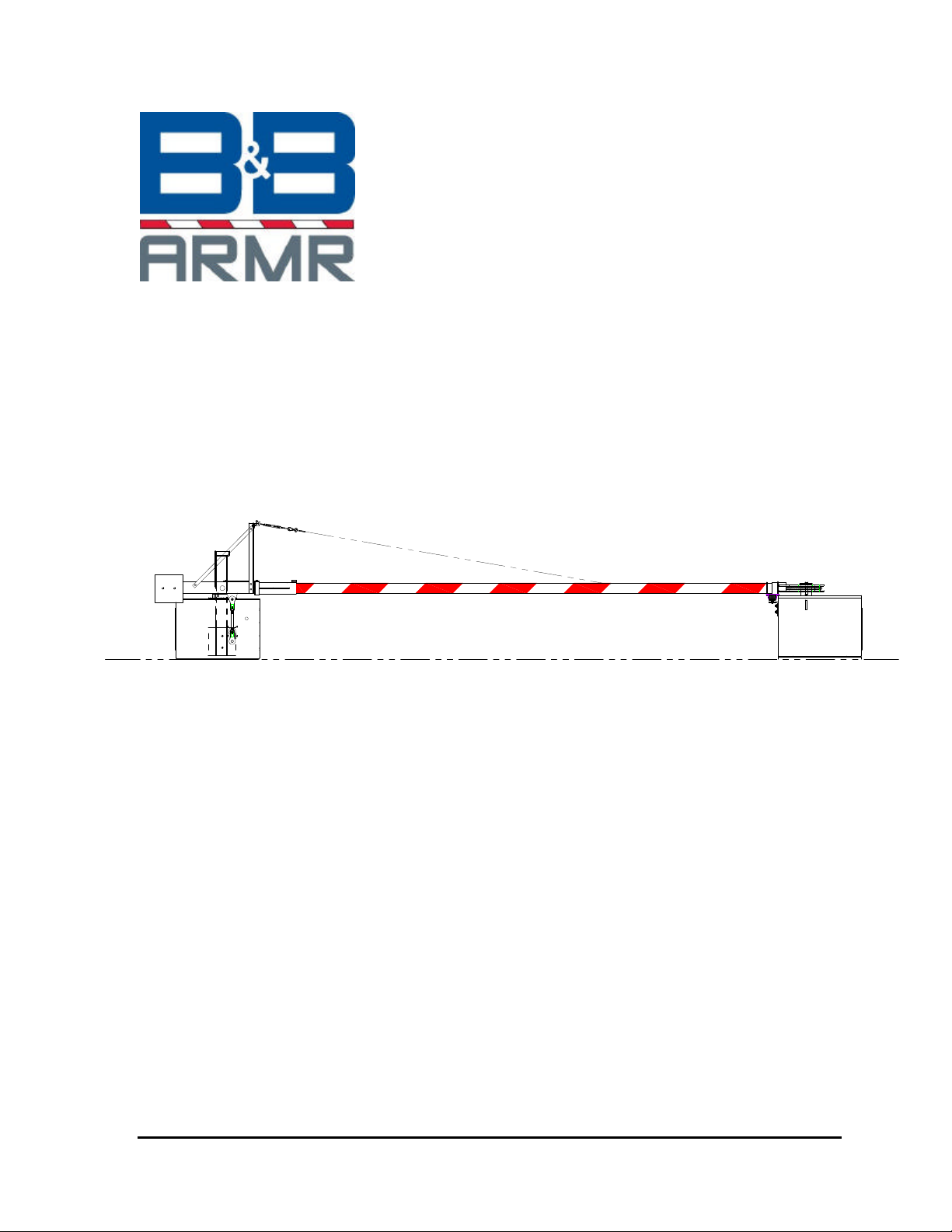
MODEL CR-25E
Cable Beam Barrier
INSTALLATION AND OPERATIONS
MANUAL
B&B ARMR CORPORATION
CORPORATE AND
TECHNICAL SUPPORT: FIELD SERVICE SUPPORT:
2009 CHENAULT DRIVE 1934 OLD GALLOWS ROAD
SUITE 114
CARROLLTON, TX 75006 VIENNA, VA 22182
TELEPHONE: (800) 367-0387 TELEPHONE: (703) 752-6108
FAX: (972) 385-9887 FAX: (703) 752-6288
MADE IN THE USA
© 2007 B&B ARMR B&B ARMR Rev C
Page 2

Installation & Operations Manual
CR-25E Cable Beam Barrier Introduction ii
INTRODUCTION
Welcome
Congratulations on your purchase of a B&B ARMR warning gate. We have years of experience
in all aspects of perimeter security and related disciplines, and our products are used
throughout the world to control access and to protect people, equipment, and facilities. Your
warning gate is designed to give you years of smooth, trouble-free operation.
In addition to providing detailed operating instructions, this manual describes how to install,
maintain, and troubleshoot your vehicle barrier. To make it easy to locate the information you
need, we've included a detailed Table of Contents immediately following this Introduction. All
of this is important information, so be sure to keep the manual available for reference.
If you need help with any aspect of your vehicle barrier's installation or operation, please
contact us. We offer a broad range of vehicle barrier and related security services, so you can
also call on us for:
• Turnkey installations
• Routine barrier preventative maintenance or emergency repairs (including work on non-
B&B ARMR products)
• Spare or replacement parts
• Custom designs or special installations
• Equipment upgrades (modernize your old equipment with state-of-the-art hydraulics
and control systems)
• Ancillary security equipment (such as security guard enclosures, card readers, security
lighting, and so on)
Safety
Your safety is important to us. If you have any questions or are in doubt about any aspect of
the equipment, please contact us. While B&B ARMR does not assume responsibility for injury
to persons or property during installation, operation, or maintenance, we can provide verbal
guidance, additional written instructions, or the services of a factory engineer. We're here to
help you operate your vehicle barrier safely and effectively.
© 2007 B&B ARMR WWW.BB-ARMR.COM (800) 367-0387
Page 3

Installation & Operations Manual
CR-25E Cable Beam Barrier Introduction iii
As the user, you are responsible for correct and safe installation, operation, and maintenance of
this equipment. Users must follow the specific instructions and safety precautions located in
this manual. In addition they must:
• Be aware of and follow the safety standards of the Occupational Safety and Health
Administration (OSHA), as well as other applicable federal, state, and local safety
regulations and industry standards and procedures. For installation outside the United
States, users must also follow applicable international, regional, and local safety
standards.
• Engage only experienced staff, properly trained, to install, operate, and maintain the
equipment.
• Ensure that all repairs are performed correctly, using properly trained staff and the right
tools and equipment.
How to Contact Us
If you have any questions or experience any problems with your vehicle barrier—or if we can
help you with any other facility security issues—please contact us directly at:
CORPORATE AND
TECHNICAL SUPPORT: SERVICE SUPPORT:
2009 Chenault Drive 1934 Old Gallows Road
Suite 114
Carrollton, TX 75006 Vienna, VA 22182
Telephone: (800) 367-0387 Telephone: (703) 752-6108
Fax: (972) 385-9887 Fax: (703) 752-6288
E-mail: info@bb-armr.com
© 2007 B&B ARMR WWW.BB-ARMR.COM (800) 367-0387
Page 4

Installation & Operations Manual
CR-25E Cable Beam Barrier Table of Contents iii
Table of Contents
INTRODUCTION .......................................................................................................ii
Welcome........................................................................................................................................................ii
Safety...........................................................................................................................................................ii
How to Contact Us........................................................................................................................................iii
1. INSTALLATION, ADJUSTMENT AND MAINTENANCE............................4
1.1 CR-25E Installation Instructions (Reference Drawing: 0025-0050-A)....................................... 4
1.2 CR-25E Start Up Instructions...................................................................................................... 6
1.3 CR-25E Shut Down Instructions.................................................................................................. 6
1.4 CR-25E Emergency Operation Instructions................................................................................ 6
1.5 CR-25E Lubrication Instructions (Reference Drawing: 0025-0053-B)....................................... 7
1.6 Lubrication Replacement Instructions......................................................................................... 8
1.7 Recommended Replacement Oils for CR-25E ............................................................................. 9
1.8 Brake Assembly Instructions (Reference Drawing: 0040-0023-C) ........................................... 10
1.9 Motor Replacement Instructions................................................................................................ 11
1.10 Limit Switch Replacement Instructions...................................................................................... 12
1.11 Field Balancing Instructions..................................................................................................... 13
1.12 Gate Arm Balancing Instructions.............................................................................................. 14
1.13 Adjusting the Barrier Movement ............................................................................................... 15
2. SPECIFICATIONS..............................................................................................19
3. ACCESSORIES AND MAJOR COMPONENTS.............................................. 22
3.1 Housing Assembly – 0025-0050-A............................................................................................. 22
3.2 Operator Assembly – 0025-0053-B........................................................................................... 23
3.3 Brake Assembly – 0040-0023-C................................................................................................ 24
3.4 Limit Switch Assembly - 0040-0009-F....................................................................................... 25
3.5 Motor Cut Sheet......................................................................................................................... 26
4. SYSTEM DRAWINGS........................................................................................ 27
4.1 Installation – 22’ Clear Opening............................................................................................... 27
4.2 Installation – 14’ Clear Opening............................................................................................... 28
4.3 Wiring........................................................................................................................................ 29
5. WARRANTY ....................................................................................................... 30
© 2007 B&B ARMR WWW.BB-ARMR.COM (800) 367-0387
Page 5

Installation & Operations Manual
CR-25E Cable Beam Barrier Installation, Adjustment & Maintenance 4 of 31
1. INSTALLATION, ADJUSTMENT AND MAINTENANCE
1.1 CR-25E Installation Instructions (Reference Drawing: 0025-0050-A)
NOTE: Failure to install your barrier properly could cause damage to the
operating mechanism.
1. Read the instructions and review the drawings thoroughly. If you do not
understand any part of these instructions, please contact the manufacturer.
2. Check the anchor bolt locations and prepare the foundation for the barrier. Set the
barrier operator and be sure to seal the bottom with duct seal. Housing must be
level. Anchor bolts must be tightened evenly.
3. Make sure the local power supply for the motor and control circuit are correct.
*Reference the enclosed electrical drawing in the back of the handbook.
IMPORTANT: All conduit must be sealed and the housing grounded.
4. Using the hand crank, turn the drive crank 45 degrees noting rotation of the drive
crank should be clockwise.
5. Open main disconnect switch (S1) and connect the power. Connect the control
circuit if separate. If power is supplied from the motor circuit, check the
connections at the terminals.
NOTE: At this point in the installation, no counterweights or arms should
have been installed.
6. "Bump" test barrier operator for correct motor rotation.
NOTE: The drive cranks should rotate upwards toward roadway to raise
barrier arm (viewing barrier operator from either drive crank side of
the housing).
7. Run barrier operator (without arms or counterweights) through several complete
cycles. Leave the barrier operator in the closed to traffic position and open the
main disconnect switch.
© 2007 B&B ARMR WWW.BB-ARMR.COM (800) 367-0387
Page 6

Installation & Operations Manual
CR-25E Cable Beam Barrier Installation, Adjustment & Maintenance 5 of 31
NOTE: This barrier has been completely assembled and test run through 24
complete cycles under full power at the factory. If satisfactory
operation is not displayed in step #7, recheck all electrical connections
carefully. CONSULT FACTORY IF PROBLEM IS NOT FOUND.
8. Remove side arm tube cover plate (Item #2). Locate pillow block bearings (Item
#12). Do not tighten set screws. Now center assembly with housing. When
assembly is correctly centered, tighten bearing set screws.
9. Insert arm, with endlock intact, into the main arm tube base. Push tube far
enough to make the cable, connections at the pivot. After cables have been
securely bolted to the pivot mechanism, extend arm so that the endlock saddles
satisfactorily over the anchor assembly (on the bollard). Slide lock coller into
place and tighten allen bolts.
NOTE 6: If endlock fails to line up properly, loosen bearing bolts and rotate
laterally. Re-tighten bolts. Now tighten arm base bolts securely.
Replace side arm tube cover plate (tighten bolts securely).
10. With the arm in the down position, install the allotted amount of counterweights
(Item #3) on the side arm tube assembly. Tighten bolts securely.
11. Close the main disconnect switch (S1) and operate the control circuit. If all
connections are made correct, barrier arm will operate to fully up or fully down.
The limit switch will automatically stop the motor at the extreme 90-degree
movement of the arm.
12. With the barrier in the lowered position, check endlock mechanism for any type
of hindrance with bollard post and adjust accordingly if required.
IMPORTANT: IF THREE PHASE POWERE CONNECTIONS TO THE
MOTOR ARE REVERSED, THE LIMIT SWITCH WILL
AUTOMATICALLY DISCONNECT THE MOTOR WHEN THE
DRIVE CRANK HAS ROTATED ABOUT 30 DEGREES IN THE
INCORRECT DIRECTION, DEPENDING ON THE POSITION OF
THE CONTROLS, i.e., UP OR DOWN. DRIVE CRANK MUST
THEN ROTATE BACK TO ORIGINAL (VERTICAL) POSITION
USING HANDCRANK, IN ORDER TO RESET BARRIER.
If this problem occurs, phase must be reversed. The limit switch has
been set at the factory and should NOT REQUIRE ADJUSTMENT.
Arm should be raised or lowered by lengthening or shortening of the
connecting rod not by adjustment of the limit switch cams.
© 2007 B&B ARMR WWW.BB-ARMR.COM (800) 367-0387
Page 7

Installation & Operations Manual
CR-25E Cable Beam Barrier Installation, Adjustment & Maintenance 6 of 31
1.2 CR-25E Start Up Instructions
NOTE: These instructions assume installation has been completed. If
necessary, refer to the enclosed installation instructions.
1. Remove the rear operator door.
2. Connect power by flipping the disconnect switch to the "ON" position.
3. Test operate the barrier to be sure it is functioning properly.
1.3 CR-25E Shut Down Instructions
1. Remove the rear operator door.
2. Disconnect power by flipping the disconnect switch to the "OFF" position.
1.4 CR-25E Emergency Operation Instructions
1. Remove the rear operator door.
2. Disconnect power by flipping the disconnect switch to the "OFF" position.
3. Locate the hand-crank mounted inside the housing.
4. Slip the hand-crank onto the shaft extending through the brake. The brake will
automatically release.
5. Turn the hand-crank to raise or lower the barrier, as needed. A tag on the brake
indicates crank direction for opening or closing the barrier. (Clockwise for
“Close”, counter clockwise for “Open”).
6. Remove the hand-crank.
7. Flip the disconnect switch back to the "ON" position to resume powered
operation.
© 2007 B&B ARMR WWW.BB-ARMR.COM (800) 367-0387
Page 8

Installation & Operations Manual
CR-25E Cable Beam Barrier Installation, Adjustment & Maintenance 7 of 31
1.5 CR-25E Lubrication Instructions (Reference Drawing: 0025-0053-B)
Mechanism lubrication should be checked at least once per month.
Transmission (Item 5 on Assembly drawing):
First gear drive box ( High speed housing):
1. Remove the front door of the housing (roadway side).
2. Check oil by removing the oil level plug located on the left-hand vertical
surface of the transmission a few inches below the motor.
Note: Some barriers may have site glasses.
a. If oil is visible, oil level is adequate - replace plug and go to
next section.
b. If oil is not visible, go to step 3.
3. Remove fill plug of first gear box located on top of gear box facing door).
4. Fill the case to the level plug or site glass (removed in step two) with multi-
grade Mobil SHC 629 or a direct replacement. (See recommended
replacement oils on the following page.)
5. Replace plugs.
Final drive gear box (Low speed housing):
1. Remove the back door of the housing (counterweight side).
2. Check the oil level by removing the oil level plug located on the left-hand
vertical surface of transmission. Note: Some barriers may have site
glasses.
a. If oil is visible, oil level is adequate - replace the plug and go to
next section.
b. If oil is not visible, go to Step 2.
2. Remove oil fill plug on final gear box, on the left-hand vertical surface,
top.
3. Fill the case to the level plug or site glass (removed in step one) with
multi-grade Mobil SHC 629 or a direct replacement. (see recommended
replacement oils on the following page)
4. Replace plugs.
Pillow Block Bearings:
1. Grease with Texaco Marfak 2 or equal.
2. Wipe off excess.
NOTE: 1 pillow block bearing is located inside unit on main shaft.
© 2007 B&B ARMR WWW.BB-ARMR.COM (800) 367-0387
Page 9

Installation & Operations Manual
CR-25E Cable Beam Barrier Installation, Adjustment & Maintenance 8 of 31
Connecting Rod Ends (Items11 & 13):
1. Grease with Texaco Marfak 2 or equal.
2. Wipe off excess.
Limit Switch Drive Chain (Item 8):
1. Spray chain with any good aerosol chain lube.
2. Wipe off excess.
1.6 Lubrication Replacement Instructions
Lubricate mechanism every 12 months with a manufacturer approved lubricant.
First gear drive box ( High speed housing):
1. Standing in front of the operator (roadway side) remove the door.
2. Locate drain plug on the bottom horizontal surface of the gear change box directly
under the motor. (Motor is horizontally mounted).
3. Position catch pan under drain plug.
4. Remove the oil fill plug on the top of gear box facing door.
5. Remove the drain plug until the oil is completely drained, then replace plug.
6. Remove the oil level plug.
7. Refill gear change box until oil flows from the oil level hole. Replug the oil fill
hole and the oil level hole.
Final drive gear box (Low speed housing):
1. Remove back door. Oil fill plug is located on the left-hand vertical surface, top.
Remove oil fill plug.
2. Standing in front of the operator (roadway side), remove the door.
3. Locate drain plug on the vertical surface of the final output gear box.
4. Position catch pan under drain plug.
5. Remove the drain plug until the oil is completely drained, then replace plug.
6. Remove the oil level plug.
7. Refill final output box until oil flows from the oil level hole. Replug the oil fill
hole and the oil level hole.
© 2007 B&B ARMR WWW.BB-ARMR.COM (800) 367-0387
Page 10

Installation & Operations Manual
CR-25E Cable Beam Barrier Installation, Adjustment & Maintenance 9 of 31
1.7 Recommended Replacement Oils for CR-25E
Direct replacement of oils is very complicated and should be considered carefully when
doing so. The following oils are recommended by the manufacturer of the transmissions
on the warning gates and barriers.
The multi-grade Mobil SHC 629 synthetic oil is the manufacturers first choice. If this oil
is not available, Exxon Terrestic SHP 150 can be used as a direct replacement. The
temperature range is -30°F to 165°F.
If neither of the two above mentioned oils is available, almost any ISO Grade 150 or
AGMA Lubricant #4 with a pour point of -40°F or less & a viscosity of approx. 726
(SUS@100°F) is acceptable.
The following grease is recommended by the manufacturer of the flange type bearings
used on both the warning gates and barriers.
Texaco Marfax or Texaco Starplex grease is the manufacturers first choice. If this grease
is not available, consult your local supplier for an equivalent.
© 2007 B&B ARMR WWW.BB-ARMR.COM (800) 367-0387
Page 11

Installation & Operations Manual
CR-25E Cable Beam Barrier Installation, Adjustment & Maintenance 10 of 31
1.8 Brake Assembly Instructions (Reference Drawing: 0040-0023-C)
IMPORTANT: Unless specified, the replacement brake assembly does not include a
solenoid or a brake drum. If these items are required, they must be requested separately,
please specify the motor voltage.
WARNING: DISCONNECT BARRIER POWER BY THROWING THE MAIN
POWER SWITCH (S1) OFF BEFORE REMOVING THE OLD
BRAKE ASSEMBLY.
Item numbers refer to the brake drawing included in the major components section of this
handbook.
To remove the old assembly:
1. Remove the Brake Release Stub (Item 9) from its bracket.
2. Remove the Brake Drum (Item 2) set screw. The set screw is located on the
side of the brake drum, even with the key in its center.
3. Pull the drum off of its shaft.
4. Disconnect the wires from the brake release solenoid (Item 5).
5. Remove the brake assembly mounting bolts, and lift off the brake assembly.
To mount the new assembly:
1. Place the new brake assembly on top of the motor, align the mounting holes,
and tighten the mounting bolts.
2. Unless a new solenoid was requested, the brake solenoid from the old brake
assembly will need to be re-mounted on the new assembly.
• Disconnect the solenoid arm from the solenoid release rod (Item 7).
• Remove the solenoid mounting screws.
• Place the solenoid (Item 5) on the new brake assembly, align the holes and
replace the mounting bolts.
• Reconnect the solenoid plunger to the solenoid release rod.
• Reconnect power wires to the solenoid.
3. Insert the brake drum onto the keyed shaft and tighten the set-screw.
4. Re-install the manual release stub onto its mounting bracket.
5. Re-apply power to the barrier, and test the brake by running the operator.
6. If the solenoid makes a loud buzzing sound, it is binding and needs to be
adjusted.
• Loosen the mounting bolts and activate the operator. The solenoid should seat
itself properly.
• Re-tighten the mounting bolts.
© 2007 B&B ARMR WWW.BB-ARMR.COM (800) 367-0387
Page 12

Installation & Operations Manual
CR-25E Cable Beam Barrier Installation, Adjustment & Maintenance 11 of 31
If the solenoid continues to buzz, the solenoid release rod may be out of
alignment. Loosening the screw between the Solenoid Plunger and Release
Rod (Item 7) should alleviate this. If the problem persists, contact the
manufacturer.
1.9 Motor Replacement Instructions
IMPORTANT: Before replacing the motor, check that the new motor is identical to
the old in voltage, phase and horsepower.
WARNING: DISCONNECT BARRIER POWER BY THROWING THE MAIN
POWER SWITCH (S1) OFF BEFORE CHANGING MOTORS.
1. Remove the brake assembly (see previous instructions)
2. Have a qualified electrician disconnect the motor wires from the junction box
on the side of the motor.
3. Remove the four motor mounting bolts located at the base of the motor.
4. Pull the motor up, out of the transmission, making sure the feather key comes
out with the motor shaft.
5. Mount the new motor, inserting the keyed shaft into the transmission and
aligning the mounting holes.
6. Have a qualified electrician reconnect the motor wires at the junction box on
the side of the motor.
7. Re-mount the brake assembly (see previous instructions).
8. Re-apply power to the operator and run the barrier several times. If the barrier
does not run satisfactorily, contact the manufacturer.
© 2007 B&B ARMR WWW.BB-ARMR.COM (800) 367-0387
Page 13

Installation & Operations Manual
CR-25E Cable Beam Barrier Installation, Adjustment & Maintenance 12 of 31
1.10 Limit Switch Replacement Instructions
WARNING: DISCONNECT BARRIER POWER BY THROWING THE
MAIN POWER SWITCH (S1) OFF BEFORE BEGINNING.
1. Remove the old limit switch from the barrier limit switch assembly by
removing the mounting screws and connecting wires.
NOTE: Mark chain and drive sprocket for proper reinstallation alignment.
2. Install the new limit switch by aligning the mounting holes, replacing the
mounting screws and re-connecting wires as removed from defective switch.
NOTE: Visually set cams and drive sprocket to match defective unit before
installation.
3. Apply power to the barrier and run it several times. If the barrier does not
operate satisfactorily, contact the manufacturer.
© 2007 B&B ARMR WWW.BB-ARMR.COM (800) 367-0387
Page 14

Installation & Operations Manual
CR-25E Cable Beam Barrier Installation, Adjustment & Maintenance 13 of 31
1.11 Field Balancing Instructions
IMPORTANT: EVERY BARRIER IS BALANCED AT THE FACTORY BEFORE IT IS SHIPPED. IF
ANY ADDITIONS OR CHANGES ARE MADE TO THE BARRIER ARM IN THE FIELD, THE
BARRIER MAY REQUIRE RE-BALANCING. AN UNBALANCED ARM MAY DAMAGE THE
OPERATOR.
If any additions or changes are made to the barrier, the following guidelines will help you
determine what changes, if any, need to be made to the barrier balance:
1. Make the desired changes to the barrier arm.
2. Secure the tip end of the arm to prevent injury or accident.
3. Disconnect the connecting rod which runs between the upper and lower cranks,
this will free the arm to be balanced.
INDICATIONS PROBLEM SOLUTION
Barrier arm tends to raise
Requires more than 20 lbs. to
Barrier is counterweight
heavy.
1. Counterweights can be
removed.
keep it closed to traffic.
Barrier arm tends to lower
Barrier is arm heavy. 1. Counterweights can be added.
Requires more than 20 lbs. to
keep it open to traffic.
A properly balanced barrier can be manually operated by one person pushing on the end
of the counterweight mounting channel. It should require only 20 lbs. of force to
manually operate the barrier. For detailed instructions on balancing the operator with
weights, refer to the next page.
© 2007 B&B ARMR WWW.BB-ARMR.COM (800) 367-0387
Page 15

Installation & Operations Manual
CR-25E Cable Beam Barrier Installation, Adjustment & Maintenance 14 of 31
1.12 Gate Arm Balancing Instructions
These adjustments are set at the manufacturing facility and should not need to be adjusted
in the field unless the arms have been modified, causing the weight of the arm to change.
Calculating Counterweight Requirements
1. Disconnect arm drive by removing top connecting rod bolts located on each side of
the operator.
2. Mark any place on the barrier arm and attach a weighing scale to the arm at that
point.
3. Measure how much weight, in pounds, it takes to start raising the barrier arm. (arm
lbs.)
4. Measure, in inches, the distance from the weight point to the center of the pivot point
(arm distance).
5. Measure, in inches, the distance from center of pivot point to center of
counterweight (counterweight distance).
6. Follow this formula to get the proper amount of counterweight to add to barrier.
arm lbs. x arm dist.
cw dist.
COUNTERWEIGHT SIZES
12”X12”X1” THICK = 41 POUNDS
12”X12”X2” THICK = 82 POUNDS
© 2007 B&B ARMR WWW.BB-ARMR.COM (800) 367-0387
Page 16

Installation & Operations Manual
CR-25E Cable Beam Barrier Installation, Adjustment & Maintenance 15 of 31
1.13 Adjusting the Barrier Movement
When installing or maintaining a CR-25 barrier, setting the limit switches and connecting
rod length properly can be confusing at times. The following instructions are intended to
clarify this process. The steps can be broken into two sections, setting crank orientation,
and setting barrier starting and stopping points.
SECTION 1: SETTING THE CRANK ORIENTATION AND ROTATION USING
THE LIMIT SWITCHES
A standard CR-25 barrier operator with 90 degrees of travel is designed so that the barrier
arm accelerates and decelerates smoothly as it pivots. This is achieved through the
lengths of the two crank arms. In order to optimize this “sinusoidal” movement, the
following steps should be followed when installing the operator.
© 2007 B&B ARMR WWW.BB-ARMR.COM (800) 367-0387
Page 17

Installation & Operations Manual
CR-25E Cable Beam Barrier Installation, Adjustment & Maintenance 16 of 31
1) Determine the direction of rotation of the cranks. In a standard installation, the cranks
pivot toward the motor, and the roadway.
The limit switch cams rotate the same direction that the pivot rotates. Cam 1 is always
the raise stop, Cam 2 is always the lower stop, Cam 3 generally controls the arm lights if
there are any.
IMPORTANT: Always power down at the main switch before adjusting the limit
switches.
2) Manually rotate the barrier into its fully open to traffic (raised) position by inserting
the manual crank onto the shaft extending from the top of the motor and turning it
until the barrier reaches the desired position.
Note: At fully open, the connecting rods should be parallel with the sides of the operator
and with the cranks. The cranks should be pointing straight up.
3) With an allen wrench loosen the limit switch cams just enough so that they will turn,
but not so much that they are loose.
4) Rotate Cam 1 until the limit switch follower just falls off of the edge of the cam. Keep
the direction of rotation of the cam in mind as you set it to ensure that when the barrier
rotates, the limit switch follower will move back onto the cam.
© 2007 B&B ARMR WWW.BB-ARMR.COM (800) 367-0387
Page 18

Installation & Operations Manual
CR-25E Cable Beam Barrier Installation, Adjustment & Maintenance 17 of 31
5) Manually rotate the barrier into its fully closed to traffic position.
Note: At fully closed, the lower drive crank should have rotated through 180 degrees, and
should be pointing straight down. The connecting rods should be parallel with the sides
of the housing and the cranks.
6) Rotate Cam 2 until the limit switch follower just falls off of the edge of the cam. Keep
the direction of rotation of the cam in mind as you set it to ensure that when the barrier
rotates, the limit switch follower will move back onto the cam.
7) Re-apply power and run the barrier open and closed. If the cams require more
adjustment it is important to disconnect power before moving the limit switch cams.
Be sure to re-tighten the limit switch cams once they have been properly set.
NOTE: At this point in the adjustment, the crank orientation is more important than the
barrier position. At the fully open and fully closed positions, the connecting rods should
be parallel with the sides of the housing, and the drive cranks should point directly up or
directly down.
STEP TWO: ADJUSTING THE STOPPING AND STARTING POINTS OF THE
BARRIER ARM
If the starting and stopping points of the barrier arm need to be adjusted, this will be done
using the connecting rods. This should only be done if the cranks and connecting rods
positions are correct as described above.
© 2007 B&B ARMR WWW.BB-ARMR.COM (800) 367-0387
Page 19

Installation & Operations Manual
CR-25E Cable Beam Barrier Installation, Adjustment & Maintenance 18 of 31
8) With the barrier in the fully raised or lowered position, loosen the lock nuts on the
connecting rods and turn the rods to increase or decrease their length. Adjust the rods
until the barrier arm is in the desired position.
NOTE: Adjusting the connecting rods changes both the raised and lowered position by
the same amount.
9) Run the barrier through several cycles to ensure proper starting and stopping points.
10) If the barrier panel travels slightly too far in either the open or closed direction, this
can be adjusted using the limit switches. It is important to note that adjusting the limit
switch at this point will stop the barrier arm before it has fully decelerated.
© 2007 B&B ARMR WWW.BB-ARMR.COM (800) 367-0387
Page 20

Installation & Operations Manual
CR-25E Cable Beam Barrier Specifications 19 of 31
2. SPECIFICATIONS
APPLICATIONS
The CR-25 Electromechanical Crash Beam Barrier Gate will typically be used as a safety
barrier. Typical applications will include embassies, nuclear facilities, "High-Risk" AtGrade crossings, government facilities where safety is an important consideration.
ENERGY ABSORPTION CAPACITY
The manual version of the CR-25 crash beam with 3/4" cable has been successfully crash
tested per U.S. Navy specifications (OR-98-09-88 and M-56-86-05 with a level 1/L2
rating) and Department of the Army rating level of KN1-LN2. It is also listed by the U.S.
Army Corps of Engineers in their document Protection Against Malevolent Use of
Vehicles at Nuclear Power Plants (NUREG/CR-6190 Vol. 2, Rev. 1).
HOUSING
The housing will be fabricated from 3/8-inch steel plate and will be hot dip galvanized
after fabrication. Formed, channel shaped side plates will be used to produce a strong
configuration without welded corners. The housing will receive a finish coat of
aluminum paint.
Access doors will be provided to service the operating mechanism and electrical
equipment. The doors will be sealed with neoprene strip gaskets and bolted in place
with corrosion-resistant, hex-head bolts.
The housing base will provide twelve 1-1/4 inch holes for mounting on the customer's
foundation. Anchor bolts and template will be supplied by the gate manufacturer.
Standard anchor bolts size will be 1.125-7 UNC X 2’-9” Long hot dip galvanized.
ARM
The beam arm will be constructed from 4-inch 6061-T6 aluminum pipe which will
contain the wire rope assembly. Maximum arm length will be 25 feet.
Dimension "A", Shall be measured from the centerline of the pivot to the centerline of the
bollard, will not exceed 322 inches. See Installation drawings for arm lengths.
Gate arms will be covered with 16-inch alternating red and white engineering grade
reflective sheeting.
ARM MOUNTING TUBES
Arm mounting tubes will be hot dip galvanized carbon steel. The roadway arm shaft
centerline will be 30-1/2 inches above the base line of the gate housing.
COUNTERWEIGHTS
Each gate will be equipped with suitable hot dip galvanized steel counterweights of the
sectional, bolt-on type.
ARM SHAFTS
© 2007 B&B ARMR WWW.BB-ARMR.COM (800) 367-0387
Page 21

Installation & Operations Manual
CR-25E Cable Beam Barrier Specifications 20 of 31
The main arm shaft will be mounted in heavy duty ball bearings. The main arm shaft will
be not less than 2 inches in diameter. Shaft material will be ASTM A311 Class B high
strength, stressproof steel.
TRANSMISSION
The transmission will be a fully enclosed, all gear, direct drive unit running in an oil bath.
The drive train will not use belts or chains and will be connected to the arm shaft with a
connecting rod having self-aligning ball ends. The connecting rod will be constructed of
ASTM A311 Class B high strength stressproof steel.
During the opening and closing cycles, the gate arm will begin with zero velocity and
accelerate smoothly reaching maximum velocity at mid-stroke (45 degrees). The arm
will then decelerate smoothly to zero velocity at full stroke (90 degrees) preventing
bounce or whip of the arm. Standard operating time to open or close the gate will be 13
seconds. Consult the factory for other available speeds.
MOTOR
A 110V, 1/2HP Single Phase motor will be supplied. The motor will be of the flange
mounted type, attached to the transmission case with not less than four bolts. The motor
will be of the instant reversing type to permit reversing movement of the arms at any
point of travel. Motor data will appear in the manual.
BRAKING MECHANISM
A solenoid release, automatic motor brake will be furnished as part of the gate drive
mechanism. The brake will automatically release when the handcrank is inserted to
manually operate the gate.
HANDCRANK
A handcrank and drill crank will be included with each gate to operate the gate during
power failure. An automatic safety disconnect switch will automatically break the
control circuit power when the handcrank is inserted to allow for manual operation.
LIMIT SWITCH
The gate limit switch will be a unit assembly containing eight individual switches having
one set of normally open and one set of normally closed contacts each. Contacts will be
totally enclosed and will have U.L. rating of not less than 15 amperes at 220 volts AC.
Limit switch will be readily accessible and easily replaced with normal hand tools. Each
individual switch will be controlled by an independent cam, which will be adjustable with
a hex socket cap screw. The limit switch body, shafts and cams will be of corrosion
resistant non-ferrous materials.
© 2007 B&B ARMR WWW.BB-ARMR.COM (800) 367-0387
Page 22

Installation & Operations Manual
CR-25E Cable Beam Barrier Specifications 21 of 31
SAFETY SWITCHES, TERMINAL BLOCKS AND WIRING
To protect operating and maintenance personnel from injury during service or
installation, a manual disconnect switch will be furnished, installed and fully wired in the
main motor leads. Automatic disconnect switches will be arranged to break the control
circuit when either door is opened. Pressure type terminal blocks will be provided and
installed inside the housing on the roadway side. All control wires will terminate on
these blocks. Each terminal will be clearly labeled and all conductors will be color coded
and/or numbered. The wiring diagram will reflect such colors or numbers. A GFI
receptacle will be supplied in the gate housing. No conductor will be smaller than #16
AWG stranded. Each housing will contain a laminated electrical schematic secured to
the inside of the housing for reference by service personnel.
ENERGY ABSORPTION CABLES
A 7/8-inch diameter galvanized, double-extra improved plow steel 6 x 9 IWRC
(independent wire rope center) wire rope will provide the primary vehicle restraint
capability of the barrier. The cable will have closed, cad-plated swage sockets on each
end. Both ends of the cable will be anchored securely at the operator end of the beam
doubling the cable. The cable assembly will be enclosed inside the arm and will form a
loop at the end of the beam arm.
CABLE ANCHORING SYSTEM
The cable assembly will be designed to securely engage an anchor post at the arm end on
impact. The engaged assembly will be designed to anchor the cable assembly at each end
of the beam at all times when the arm is in the closed position to withstand collision
loads.
Engagement of the anchoring assemblies at each end will not rely upon any electrical,
hydraulic, magnetic or other powered devices. A clevis mounted on the end of the crash
beam will be designed to securely and passively engage and lock itself to the bollard
upon vehicle impact with the beam.
QUALITY ASSURANCE
Manufacturer of the traffic control gate operator will have a minimum of five years
experience in the manufacture of industrial gate operators and barriers, and will make
available replacement parts for 10 years. All gates are individually inspected at time of
final assembly and test. Each gate will be tagged "ACCEPTED" upon completion of
inspection and “Certification of Testing” will be supplied in the handbook for validation
of meeting internal Quality Assurance standards.
© 2007 B&B ARMR WWW.BB-ARMR.COM (800) 367-0387
Page 23

Installation & Operations Manual
CR-25E Cable Beam Barrier Accessories and Major Components 22 of 31
3. ACCESSORIES AND MAJOR COMPONENTS
3.1 Housing Assembly – 0025-0050-A
2009 Chenault Dr., #114
800-367-0387
Carrollton, Tx 75006
B&B ARMR
CR-25E
OPERATOR ASSEMBLY
© 2007 B&B ARMR WWW.BB-ARMR.COM (800) 367-0387
Page 24

Installation & Operations Manual
CR-25E Cable Beam Barrier Accessories and Major Components 23 of 31
3.2 Operator Assembly – 0025-0053-B
2009 Chenault Dr., #114
Carrollton, Tx 75006
800-367-0387
B&B ARMR
CR-25 BARRIER
OPERATOR ASSEMBLY
A
© 2007 B&B ARMR WWW.BB-ARMR.COM (800) 367-0387
Page 25

Installation & Operations Manual
CR-25E Cable Beam Barrier Accessories and Major Components 24 of 31
3.3 Brake Assembly – 0040-0023-C
2009 Chenault Dr., #114
800-367-0387
B&B ARMR
Carrollton, Tx 75006
UNIVERSAL VT BRAKE ASSEMBLY
© 2007 B&B ARMR WWW.BB-ARMR.COM (800) 367-0387
Page 26

Installation & Operations Manual
CR-25E Cable Beam Barrier Accessories and Major Components 25 of 31
3.4 Limit Switch Assembly - 0040-0009-F
2009 Chenault Dr., #114
Carrollton, Tx 75006
800-367-0387
B&B ARMR
8 CIRCUIT
LIMIT SWITCH ASSEMBLY
© 2007 B&B ARMR WWW.BB-ARMR.COM (800) 367-0387
Page 27

Installation & Operations Manual
CR-25E Cable Beam Barrier Accessories and Major Components 26 of 31
3.5 Motor Cut Sheet
© 2007 B&B ARMR WWW.BB-ARMR.COM (800) 367-0387
Page 28

Installation & Operations Manual
CR-25E Cable Beam Barrier System Drawings 27 of 31
4. SYSTEM DRAWINGS
4.1 Installation – 22’ Clear Opening
2009 Chenault Dr., #114
Carrollton, Tx 75006
800-367-0387
B&B ARMR
22' CLEAR OPENING
CR-25E CABLE BEAM BARRIER
© 2007 B&B ARMR WWW.BB-ARMR.COM (800) 367-0387
Page 29

Installation & Operations Manual
CR-25E Cable Beam Barrier System Drawings 28 of 31
4.2 Installation – 14’ Clear Opening
2009 Chenault Dr., #114
Carrollton, Tx 75006
800-367-0387
B&B ARMR
14' CLEAR OPENING
CR-25E CABLE BEAM BARRIER
© 2007 B&B ARMR WWW.BB-ARMR.COM (800) 367-0387
Page 30

Installation & Operations Manual
CR-25E Cable Beam Barrier System Drawings 29 of 31
4.3 Wiring
2009 Chenault Dr., #114
Carrollton, Tx 75006
B&B ARMR
110V, SINGLE PHASE, 1/2HP
CR-25E CABLE BEAM BARRIER
800-367-0387
© 2007 B&B ARMR WWW.BB-ARMR.COM (800) 367-0387
Page 31

Installation & Operations Manual
CR-25E Cable Beam Barrier Warranty 30 of 31
5. WARRANTY
B&B-ARMR CORPORATION warranties for a period of one year, after delivery F.O.B.
plant, unless otherwise specified by Supplier, from failure of operation in ordinary use
and against defects due to faulty material or workmanship. Any defective equipment in
the Barrier shall be returned to the factory, at Supplier’s option, for repair or replacement,
and Supplier assumes no responsibility for service at any consumer site. Supplier is in no
event responsible for any labor costs under the warranty. Subject to the above limitation,
all service, parts, and replacements necessary to maintain the equipment as warranted
shall be furnished by the end user. Supplier shall not have any liability under these
specifications, other than for repair or replacement as described above for equipment
malfunction or equipment failure of any kind, caused for any reason, including, but not
limited to unauthorized repairs, improper installation, installation not performed by
Supplier personnel, nor by Supplier authorized personnel, failure to perform
manufacturer’s suggested routine maintenance, modifications, misuse, accident,
catastrophe, neglect, natural disaster, act of God or if at any time the power supplied to
any part of the Security Barrier falls short or exceeds the rate of tolerance for the
equipment.
The exclusive remedy for breach of any warranty by Supplier shall be the repair or
replacement at supplier’s option, of any defects in the equipment. IN NO EVENT
SHALL THE SUPPLIER OF SECURITY BARRIER BE LIABLE FOR
CONSEQUENTIAL OR SPECIAL DAMAGES OR ANY KIND OF DAMAGES
TO ANYONE. Except as provided herein, Supplier makes no warranties or
representations to consumer or to anyone else and consumer hereby waives all liability
against Supplier as well as any other person for the design, manufacture, sale,
installation, and/or servicing of the Security Barrier.
THE FOREGOING WARRANTIES ARE IN LIEU OF ALL OTHER
WARRANTIES EXPRESS OR IMPLIED, INCLUDING THE IMPLIED
WARRANTY OF MERCHANTABILITY AND FITNESS FOR A PARTICULAR
PURPOSE. NO OTHER WARRANTIES EXIST.
Any modification or alteration by anyone other than B&B-ARMR will render the
warranty herein as null and void.
© 2007 B&B ARMR WWW.BB-ARMR.COM (800) 367-0387
 Loading...