

Page 1

WWW.BB-LOCKS.COM
INSTRUCTION MANUAL - A1 SERIES
Page 2

CHARACTERISTICS:
24V DC stabilized (+/- 5%)consumption:
2,2 A activationcurrent(<0,2sec)
130 mA holding current
controlledandmanageableaccess
immediatelylocked(onthemainboltwithathrow of 20mm) when the door closes
mechanical opening with the cylinder is alwayspossible
from the inside the lock (HX and HE) can always be opened mechanically
using the handle or panic bar (emergency exit)
integrated signalisation of the bolt position (unlocked/ locked)
integrated signalisation of the door position (open / closed)
integrated signalisation of the use of the cylinder
integrated signalisation of the use of the handle
stainlesssteellockingcomponents, cylinder block, baseplate and striker plate
the locking components are mounted on the solid baseplate using 6mm axes,
which improvesthefreemovementofthecomponents and the lifespanofthelock
integratedmicroprocessor controlledintelligence
anti-saw pin in the bolt
strikerplates (standardoradjustable)withcast on strikercup
PCB protectedinapolyurethanecasted resin
door detection by 3 Hall-sensors
testedtoachieve1.000.000cycles
testedtoafrequencyof600cycles a day
bolt resistanceupto40.000Nlateralforce
unlocking under considerablelateral pressureispossible
specially designed security escutcheons (SE-17, SE-22, SEK-17, SEH-17, SEH-22 and
SEHK-17) are available (optional)
availableforboth17mmand22mmcylinders
availableinbacksetsof25,30,35,50&60mm(SA,SX&SEmodels)
availableinbacksetsof35&60mm(HX&HEmodels)
availablewith2cylinderopenings(PSX,PSE&PMEmodels)
distancefromhandletocylinderis72mm(HX&HEmodels)
tumbler 9 mm (completeboltretraction at 30° tumbler rotation)-(HX&HEmodels)
DESCRIPTION:
The B&B Locks A1-series are electrical security locks of superior quality. Because of their very
solid construction, these locks offer an extreme high resistance against all forms of agression
and burglary attempts and are suitable for intensif use. To ensure a fast and precise action, the
hardened locking components are driven by a powerful solenoid. This solenoid was especially
designed to have the best possible balance between activation and holding current. A low
power consumption and very little heating are additional advantages thereof. Unlocking is
done by giving animpulse with a push button, card reader, code, fingerprint or any other type of
impulse generator. Mechanical unlocking is always possible using a key. The automatic locking
mechanism guarantees that the door will be locked as soon as it closes, which makes a closed
door automaticallyasecureddoor.
A1 ELECTRO-MECHANICAL SECURITY LOCK
Description & Characteristics
Page 3

Certificates EN14846
w w w . b b - l o c k s . c o m
A1 ELECTRO-MECHANICAL SECURITY LOCK
Certificates:
EN14846:2008
CERTIFICATE:
SKG-IKOB -ITT(report nr.):
Declarationof Performance (doc.nr.):
PRODUCT AND DESCRIPTION:
3
M
9
C
0
L
7
1
1
0960-CPR-SKGIKOB.009752.01.EN
13.00921
DoP1011
:
A1B__SX, A1B__SE, A1B__PSX,A1B__PSE
A1B__HX, A1B__HE
A1SRC__SX, A1SRC__SE, A1SRC__PSX, A1SRC__PSE
A1SRC__HX, A1SRC__HE
(availableon our website)
A1 fail secure series
Category of use High frequency of use in public buildings
Durability and load on latchbolt 200'000 cycles with 25N sideload
Door mass and closing force Above 200 Kg, closing force max. 15N
Suitebility for use on fire/smoke doors Suitable for use on smoke/fire doors (30 min.)
Safety -
Corrosion resistance, temperature and humidity High resistance (96h), -25°C to +70°C, level 2
Security Very high security with drill resistance
Security - electrical function Status indication
Security - electrical manipulation Electrostatic discharge EN 61000-4-2 level 2
CERTIFICATE:
SKG-IKOB - ITT(report nr.):
PRODUCT AND DESCRIPTION:
3
M
9
0
0
L
7
1
1
SKGIKOB.009753.01.EN
13.00921
:
A1B__SANOCYL, A1B__SA, A1B__PSA
A1SRC__SANOCYL, A1SRC__SA, A1SRC__PSA
A1 fail safe series
Category of use High frequency of use in public buildings
Durability and load on latchbolt 200'000 cycles with 25N sideload
Door mass and closing force Above 200 Kg, closing force max. 15N
Suitebility for use on fire/smoke doors Not intended for use on smoke/fire doors
Safety -
Corrosion resistance, temperature and humidity High resistance (96h), -25°C to +70°C, level 2
Security Very high security with drill resistance
Security - electrical function Status indication
Security - electrical manipulation Electrostatic discharge EN 61000-4-2 level 2
Page 4

A1 ELECTRO-MECHANICAL SECURITY LOCK
Certificates EN179
Certificates:
EN179:2008
CERTIFICATE:
IFT - ITT(report nr.):
Declarationof Performance (doc.nr.):
PRODUCT AND DESCRIPTION:
3
7
6
B
1
4
5
2
A
B
0960-CPR-SKGIKOB.009758.01.EN
13-000057-PR05
DoP1013
A1B__HX, A1B__HE, A1B__HA
A1SRC__HX, A1SRC__HE, A1SRC__HA
(availableon our website)
A1 lock series with handle:
In combination with one of the following lever handles:
SEH-17
SEH-22
Category of use High frequency of use (little care + chance of incidence and misuse)
Durability 200'000 test cycles
Door mass up to 200 Kg
Suitebility for use on fire/smoke doors Suitable for use on smoke/fire doors (EN1634-1)
Safety Safety function
Corrosion resistance 240 h (very high resistance)
Security 5000 N
Projection of operating element projection up to 100mm (standard projection)
Type of operation Emergency exit device with "lever handle" operation
Field of door application Outwardly opening single exit door only
Page 5
Certificates EN1125 and DIN18251
w w w . b b - l o c k s . c o m
A1 ELECTRO-MECHANICAL SECURITY LOCK
Certificates:
EN1125:2008
DIN18251 - part 1
40'000N resistance to lateral force on the bolt.
CERTIFICATE:
IFT - ITT(report nr.):
Declarationof Performance (doc.nr.):
PRODUCT AND DESCRIPTION:
3
7
6
B
1
4
2
2
A
B
0960-CPR-SKGIKOB.009760.01.EN
13-000057-PR06
DoP1014
A1B__HX, A1B__HE, A1B__HA
A1SRC__HX, A1SRC__HE, A1SRC__HA
Push-bar ECO EPN900 II-IV
Push-bar ECO EPN950
(availableon our website)
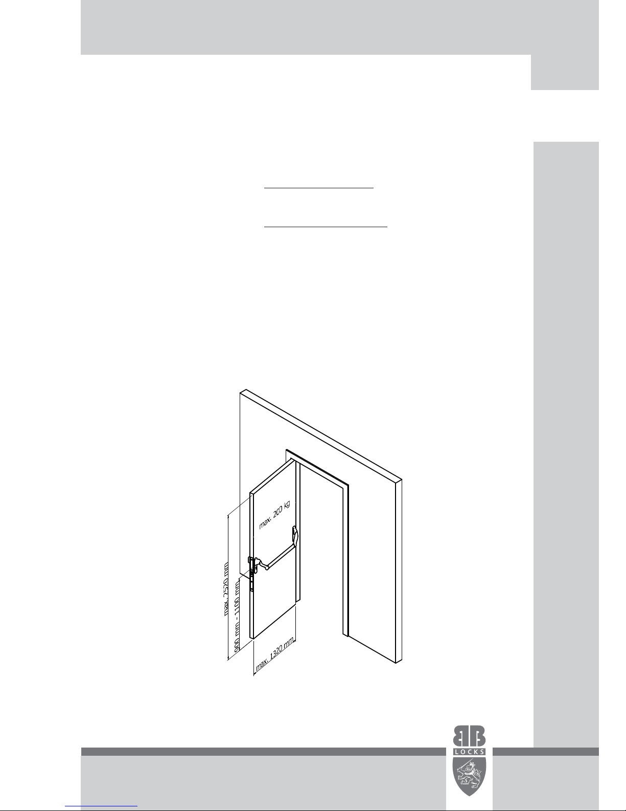
A1 lock series with handle:
In combination with Push-bar:
Category of use High frequency of use (little care + chance of incidence and misuse)
Durability 200'000 test cycles
Door mass up to 200 Kg
Suitebility for use on fire/smoke doors Suitable for use on smoke/fire doors (EN1634-1)
Safety Safety function
Corrosion resistance 240 h (very high resistance)
Security Grade 2, only one grade
Projection of operating element projection up to 100mm (standard projection)
Type of operation Panic exit device with "push-bar" operation
Field of door application Single door only
Page 6

Standard Striker Plate with
striker cup
3mm
Adjustable Striker Plate with
striker cup
6mm
Both the standardstriker plate (SSP)
and the adjustable striker plate
(ASP) have a cast on striker cup
protecting the bolt. The ASP has the
big advantage of being easily
adjustable in case the lock and the
striker plate need to get aligned
better.
Models without handle
A1 ELECTRO-MECHANICAL SECURITY LOCK
SA SANOCYL P P P&SX SXSE SE ME
AVAILABLE BACKSETS : 25, 30, 35, 50 & 60 mm AVAILABLE BACKSETS : 35 & 60 mm
SANOCYL
SA
SX
SE
:
:
:
:
unlocked without power - without cylinder block
unlocked without power - with cylinder block (mechanical opening always possible with key)
locked without power - with cylinder block (mechanical opening always possible with key)
locked without power ( ) - with cylinder block (mechanical opening
always possible with key)
: locked without power - with 2 cylinder holes
: locked without power ( ) - with 2 cylinder holes
: mechanical version - unlocking by cylinder; automatic locking when door closes
only when door is closed
only when door is closed
PSX
PSE
PME
Page 7

Models with handle
w w w . b b - l o c k s . c o m
A1 ELECTRO-MECHANICAL SECURITY LOCK
HHX E
AVAILABLE BACKSETS : 35 & 60 mm
Standard Striker Plate with
striker cup
3mm
Adjustable Striker Plate with
striker cup
6mm
Both the standard striker plate (SSP) and the adjustable striker
plate (ASP) have a cast on strikercup protectingthe bolt. The ASP
has the big advantage of being easily adjustable in case the lock
and the striker plate need toget aligned better.
HX :
HE :
Lockedwithout power. Mechanical opening withkeyis always possible fromboth sides.
Mechanical opening withthe handle isalwayspossible from thesecureside.
Lockedwithout power ( ). Mechanical openingwith key is always
possible from bothsides. Mechanical openingwith the handle isalways possiblefromthe
secure side.
The handle on the inside mechanically retracts the locking components, always granting you an authorised exit.
These HX and HE versions of the A1 locks are therefore suitable for emergency exit doors and are certified for
and European standards.
In some cases it might be desirable to prevent people from exiting a building freely. In that case a master-slave
combination (of different A1 locks) can be installed. The „slave“ will need an unlock impuls from an authorised
person or alarm; the „master-lock“ will be unlucked with the handle. Please contact us for more detailed
informationregardingpossible combinations.
only when thedoor is closed
EN179 EN1125
Page 8

Installation instructions
A1 ELECTRO-MECHANICAL SECURITY LOCK
Please make sure the following installation requirements are met to ensure the correct functioning of
your B&B A1 electro-mechanical lock :
Use BB25LSZH cable (2 x 1,5mm² + 5 x 0,22mm² - shielded).
Use 24V DC regulated POWER SUPPLYof minimum 2,5A per lock.
Makesure the distance between the power supply and the lock is maximum 25m.
Measure the voltage coming to the lock and make sure that this never drops below 22,8V (24V DC +/-
5%) - important especially when the solenoid is activated! In case of a voltage drop on the line
one can increase the TRIM 2 on the PS24D52 power supply (factory setting = 2 ).
Makesure the distance between the lock and strikerplate is min. 2mm and max. 6mm.
Make sure the lock and striker plate are installed in a proper matter where the 2 are perfectly aligned
(in closed door position they should be straight across from each other, both laterally and in
height).
Makesure that there is no friction on the bolt when being ejected and retracted (this should be tested
after installation of the rubbers on the profile).
Make sure the holes for inserting the cylinder are large enough so the cylinder can be easily installed
without being forced.
Only cylinders with the lever at 5 and 7 (o’clock)can be used:
Filings that end up in or around the lock will be attracted
when the solenoid is activated and will eventually damage the lock. Compressed air can be used
to clean out the lock if necessary.
Do not use grease or oil in the locks. The necessary areas have been libricated during the assembly at
the factory.
A standard revision is recommended aftre 300'000 cycles or 5 years.
Make sure the door is equipped with adequate hinges (according to door size and weight) to avoid
„hanging“ of the door.
Makesure the door is equipped with an adequate door closer (according to door size and weight) !
DO NOT FILEwith the lockalready installed!
Please note that in order for the lockto functioncorrectly the above mentioned specifications need to
be strictly followed. B&B LOCKS b.v.b.a. can not be held accountable for on-site interventions and
reparationsunder warranty if the installation was notdone according tothese specific instructions!
min. 2mm
max. 6mm
Page 9

Mounting possibilities
w w w . b b - l o c k s . c o m
A1 ELECTRO-MECHANICAL SECURITY LOCK
Sanocyl
SA
SX
SE
Sanocyl
SA
Sanocyl
SA
SX
SE
HX
HE
BASEPLATE FIXATION BLOCKS
(BFB)
SURFACE MOUNT BRACKETS
(SMB)
A1 locks can of course also be
installed in existing doors. Since
it is not always easy to make very
accurate adaptions to a door
when you are on site, we have
developed Baseplate Fixation
Blocks ( ). Using these
blocks the A1 lock will end up
flush mounted on the profile
(when profile used is 2mm).
BFB-1
In case it is impossible to
install the A1 lock in the door
or the door frame because of
its dimensions, a surface
mount apllication may be
considered. The Surface
Mount Bracket (SMB) consists
of 2 mounting blocks and 1
stainless steel cover (these
need to be ordered
seperately for the lock AND
forthestrikerplate).
Installation is on the secure
side!
Page 10

Notes
......................................................................................................
......................................................................................................
......................................................................................................
......................................................................................................
......................................................................................................
......................................................................................................
......................................................................................................
......................................................................................................
......................................................................................................
......................................................................................................
......................................................................................................
......................................................................................................
......................................................................................................
......................................................................................................
......................................................................................................
......................................................................................................
......................................................................................................
......................................................................................................
......................................................................................................
......................................................................................................
......................................................................................................
......................................................................................................
......................................................................................................
......................................................................................................
......................................................................................................
......................................................................................................
......................................................................................................
......................................................................................................
......................................................................................................
......................................................................................................
......................................................................................................
......................................................................................................
......................................................................................................
......................................................................................................
......................................................................................................
......................................................................................................
......................................................................................................
......................................................................................................
A1 ELECTRO-MECHANICAL SECURITY LOCK
Page 11

A1 BASIC - connection diagram
w w w . b b - l o c k s . c o m
A1 ELECTRO-MECHANICAL SECURITY LOCK
CONNECTOR 1 (2-pole):
CONNECTOR 2 (5-pole):
pin 1 = (red,
GND (blue,
,
pin 4 = BOLT SIGNAL
(brown,
(yellow,
pin 6 = KEY SIGNAL
(green,
(grey,
+24Vdc +/- 5%, 2.5A 1.5 mm²)
pin 2 = 1.5 mm²)
pin 3 = UNLOCK - opening impulse - NO contact connects pin 2 (GND) and pin 3 to unlock
(black 0.22 mm²)
0.22 mm²)
0.22 mm²)
0.22 mm²)
0.22 mm²)
- transistorswitch to GND when bolt is locked - max. charge 100mA
pin 5 = DOOR SIGNAL - transistorswitch to GND when door is closed - max. charge 100mA
- transistorswitch to GND when key is used - max. charge 100mA
pin 7 = HANDLE SIGNAL - transistorswitch to GND when handle is used - max. charge 100mA
handle OUT
unlock impulse
bolt OUT
door OUT
key OUT
power GND
power +24V
-Unlock
Internal GND (+0V)
Internal power (+24V)
Page 12

A1 BASIC - connection diagram with REL-4
A1 ELECTRO-MECHANICAL SECURITY LOCK
The REL-4 interface is available to turn the
signals coming from the lock into potential
free contacts. It also facilitates the
connection of the access control.
In order to guarantee the correct
functioning of the lock, 24Vdc (+/- 5%) /
2.5A has to reach the lock. We suggest
using our PS24D52 power supply and
BB25LSZH cable (2x1.5mm² + 5x0.22mm²).
The maximum distance between the power
supply and the lock is 25m.
Page 13

REL-4 - connection diagram
w w w . b b - l o c k s . c o m
A1 ELECTRO-MECHANICAL SECURITY LOCK
REL-4 interface:
CONNECTOR 1 (2-pole) - connection to the power supply:
CONNECTOR 2 (2-pole) - unlocking impulse:
CONNECTOR 3 (7-pole) - connection to the lock:
CONNECTOR 1 (12-pole) - potential free outputs:
DIN Rail box with user friendly Phoenix plug-in screwconnectors.
pin 1 = (red,
GND (blue,
pin 2
pin 1 = (red,
GND (blue,
(black,
pin 4 = BOLT SIGNAL brown,
(yellow,
pin 6 = KEY SIGNAL (green,
(grey,
pin 1 = BOLT common
pin 2 = BOLT locked (NO)
pin 3 = BOLT unlocked (NC)
pin 4 = DOOR common
pin 5 = DOOR closed (NO)
pin 6 = DOOR open (NC)
pin 7 = KEY common
pin 8 = KEY in use (NO)
pin 9 = KEY not in use (NC)
pin 10 = HANDLE common
pin 11 = HANDLE in use (NO)
pin 12 = HANDLE not in use (NC)
Inputs:
Outputs:
+24Vdc +/- 5%, 2.5A 1.5 mm²)
pin 2 = 1.5 mm²)
pin 1
+24Vdc +/- 5%, 2.5A 1.5 mm²)
pin 2 = 1.5 mm²)
pin 3 = UNLOCK - unlocking impulse 0.22 mm²)
0.22 mm²)
0.22 mm²)
0.22 mm²)
0.22 mm²)
(
pin 5 = DOOR SIGNAL
pin 7 = HANDLE SIGNAL
UNLOCK - NO contact connecting pin 2 (GND) to pin 3 to unlock
Page 14

A1 BASIC - connection diagram without REL-4
A1 ELECTRO-MECHANICAL SECURITY LOCK
Connection without REL-4 interface:
The unlock impulse is a NO contact, which
bridges pin 2 and 3 on the lock.
In order to guarantee the correct
functioning of the lock 24Vdc (+/-5%) / 2.5A
has to arrive at the lock. We recommend
using our PS24D52 power supply and
BB25LSZH cable (2x1.5mm² + 5x0.22mm²).
The maximum distance between the power
supply and the lock is 25m.
Page 15

A1 master-slave connection
w w w . b b - l o c k s . c o m
A1 ELECTRO-MECHANICAL SECURITY LOCK
Openen 3x A1 sloten met kruk uitgang
Voeding +24V
Voeding massa
Ontgrendel ingang
Schoot uitgang
Deur uitgang
Sleutel uitgang
Kruk uitgang
Voeding +24V
Voeding massa
Ontgrendel ingang
Schoot uitgang
Deur uitgang
Sleutel uitgang
Kruk uitgang
Voeding +24V
Voeding massa
Ontgrendel ingang
Schoot uitgang
Deur uitgang
Sleutel uitgang
Kruk uitgang
SLOT MET KRUK
It is possible to mount multiple A1 locks on 1 door in a „master-slave“ configuration
to obtain a multi-point locking system:
handle output
key output
door output
bolt output
opening impulse input
Power Supply GND
Power Supply +24V
handle output
key output
door output
bolt output
opening impulse input
Power Supply GND
Power Supply +24V
handle output
key output
door output
bolt output
opening impulse input
Power Supply GND
Power Supply +24V
Page 16

Production and sales:
Uilenbaan 88 unit 3
2160 Wommelgem
Belgium
Tel.: +32.3.326.36.30
Fax: +32.3.326.38.33
E-mail: info@bb-locks.com
B&B LOCKS b.v.b.a.
 Loading...