

Page 1
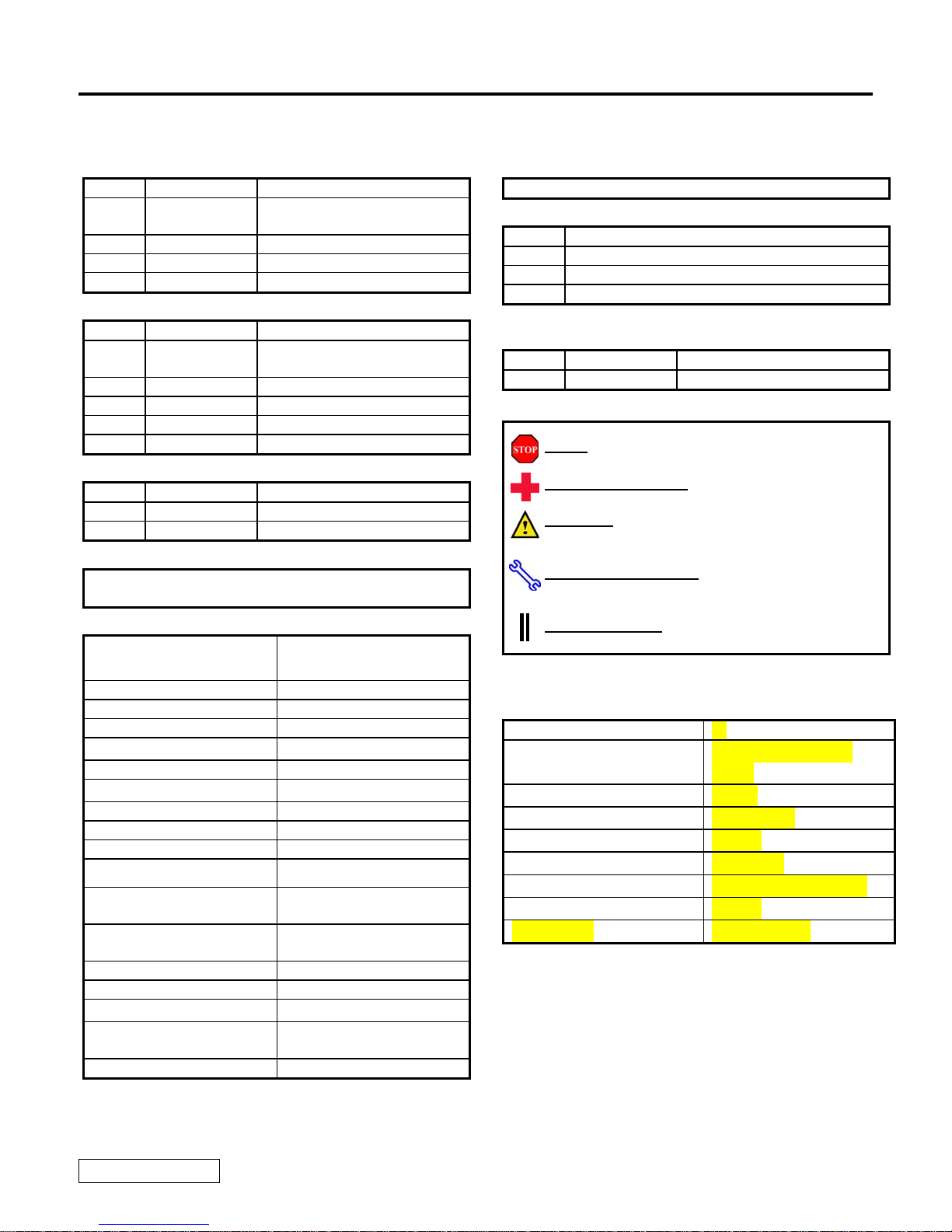
TOYOTA TUNDRA D-CAB 2004 - VSE SUBWOOFER (NON-JBL)
Preparation
Part Number: PTS20-34040 (VSE)
PTS20-34041 (Non-JBL Wire Harness)
VSE Kit Contents
Item # Quantity Reqd. Description
1 1 Vehicle Specific Enclosure
(VSE) Subwoofer
4 4 Product Feature Placard
5 1 Service Care Card
Wire Harness Bag Contents
Item # Quantity Reqd. Description
1 1 Non-JBL Audio VSE Wire
Harness
2 1 Instruction sheet
3 14 7” Wire Ties
3 1 10mm Ground Bolt
Additional Items Required For Installation
Item # Quantity Reqd. Description
1
Conflicts
None:
Recommended Tools
Personal & Vehicle
Protection
Vehicle Protection Seat/Floor Covers
Part Protection Blankets
Special Tools Notes
Installation Tools Notes
Panel Removal Tool Nylon Removal Tool (NRT)
Socket/Ratchet 10mm
Socket Extension 6 inch (optional)
Torque Wrench
Pliers 1. Diagonal Cutters
Screwdriver (Manual or
Electric)
Clip Removal Tool
Special Chemicals Notes
Cleaner 3MTM Prep Solvent–70 (if
Notes
3 lbf·ft , and 10 lbf·ft
2. Long Nose (optional)
Magnetized Philips # 2
required)
NOTE: Part number of this accessory may not be
the same as the part number shown.
General Applicability
All Tundra D-Cab Grades w/ NON JBL AUDIO
Recommended Sequence of Application
Item # Accessory
1a Install Security/Audio
1b Install VSE Subwoofer
2 Install Molded Dash
*Mandatory
Vehicle Service Parts (may be required for reassembly)
Item # Quantity Reqd. Description
1
Legend
STOP: Damage to the vehicle may occur. Do not
proceed until process has been complied with.
OPERATOR SAFETY: Use caution to avoid risk of
injury.
CAUTION: A process that must be carefully observed
in order to reduce the risk of damage to the
accessory/vehicle and to ensure a quality installation.
TOOLS & EQUIPMENT: Used in Figures calls out t
specific tools and equipment recommended for this
process.
REVISION MARK: This mark highlights a change in
installation with respect to previous issue.
Bass Tube Specifications
Woofer Size 6”
Voice Coil Size
1”high power/high
temp.
Magnet Size 15 oz.
Frequency Response 39 – 85 hz.
Efficiency 105dB
Power Handling 100 watts
Dimensions 18.125” x 8.5” x 10”
Weight 14 lbs.
Impedance 2 ohms DVC
he
Issue: A 08/16/04
Page 1 of 12 pages
Page 2
TOYOTA TUNDRA D-CAB 2004 - VSE SUBWOOFER (NON-JBL)
N
Procedure
Care must be taken when installing this accessory to ensure damage does not occur to the vehicle. The installation of this
accessory should follow approved guidelines to ensure a quality installation.
These guidelines can be found in the "Accessory Installation Practices" document.
This document covers such items as:-
• Vehicle Protection (use of covers and blankets, cleaning chemicals, etc.).
• Safety (eye protection, rechecking torque procedure, etc.).
• Vehicle Disassembly/Reassembly (panel removal, part storage, etc.).
• Electrical Component Disassembly/Reassembly (battery disconnection, connector removal, etc.).
Please see your Toyota dealer for a copy of this document.
1. Pre-installation Precautions
STOP
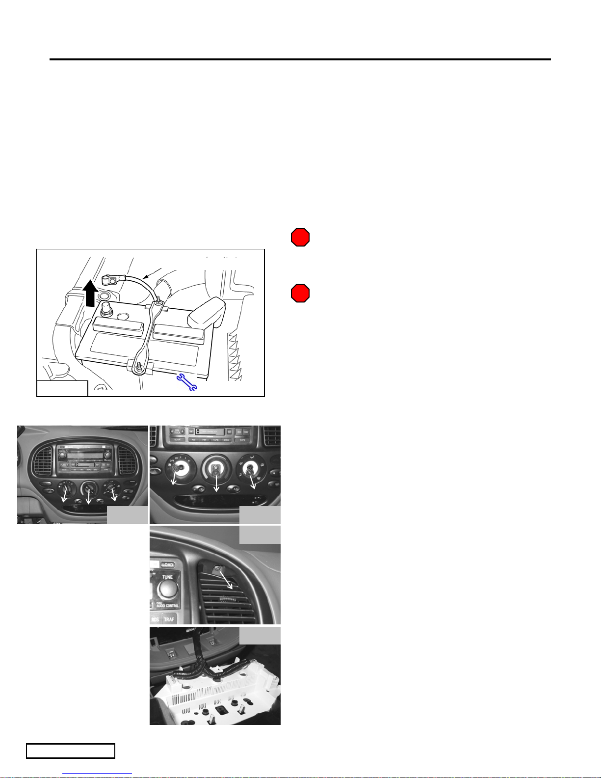
(a) Use Seat & Floor Protectors and Fender
Fig. 2a
egative Battery Cable
10 mm Socket
Fig. 3a Fig. 3b
Fig. 3d
Covers/Blankets to avoid damage to surfaces.
Operator Safety Warning (if applicable.)
STOP
(b) Place all removed parts on a protective
surface.
2. Battery Disconnect
(a) Remove the NEGATIVE (-) battery terminal
using a 10mm socket before any disassembly
starts. (Fig. 2a).
3. Disassemble Center Instrument Panel (IP)
(a) Starting with the center portion of the center
IP, pull out the three (3) ventilation control
knobs. (Fig. 3a)
(b) Using the #2 Philips Screwdriver, remove the
3 screws behind the left, right & center
climate control knobs. (Fig. 3b)
Issue: A 12/15/04
Fig. 3e
Page 2 of 12 pages
(c) Push in the top section of both center vents to
expose the screw behind each of the vents.
(1) Using the #2 Philips Screwdriver, remove
the 2 screws behind the vents. (Fig. 3c)
(d) Remove the center IP
(1) Carefully disconnect the connectors
located behind the center IP. (Fig. 3d)
(2) An NRT may be used to remove difficult
connectors from center IP.
Page 3
TOYOTA TUNDRA D-CAB 2004 - VSE SUBWOOFER (NON-JBL)
Procedure
4. Remove Radio
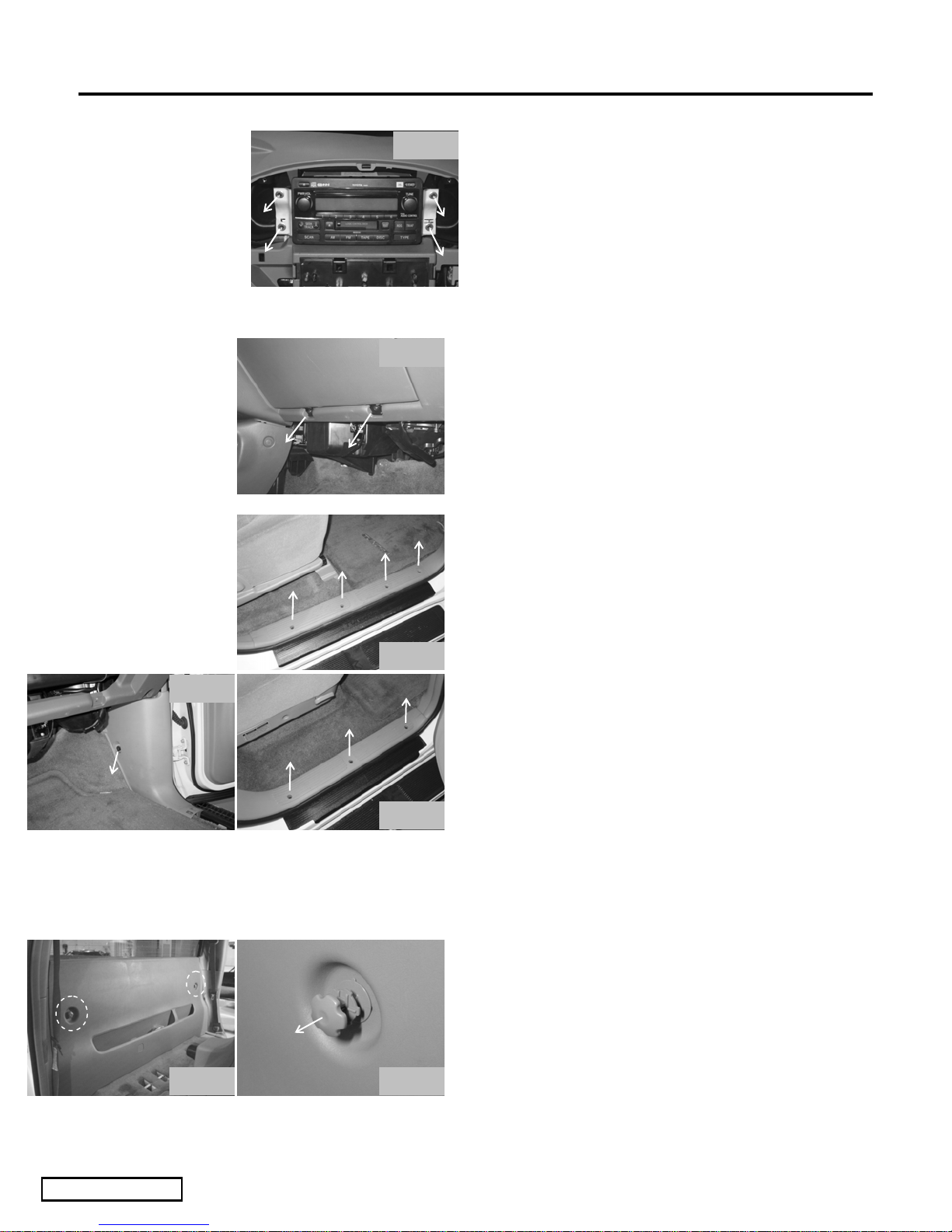
Fig. 4a
Fig. 5a
(a) With the center IP removed, use a 10mm
socket to remove the four (4) bolts from the
radio bracket. (Fig. 4a)
(b) Pull out the Radio and carefully disconnect
the connectors located behind.
(1) A NRT may be used to release difficult
connectors from the radio.
5. Disassemble Glove Compartment
(a) Using the #2 Philips Screwdriver, remove the
2 screws attached to the glove compartment
hinges. (Fig. 5a)
6. Disassemble Passenger Front & Rear Scuff
Plates & Passenger Front Kick Panel
(a) Remove the front passenger scuff plate by
Fig. 6b
Fig. 6a
Fig. 6c
removing the 4 Philips screws and carefully
pulling upward. (Fig. 6a)
(b) Remove passenger kick panel by removing
the plastic nut (located near firewall) using a
needle nose plier and pulling out the kick
panel. (Fig. 6b)
(c) Remove both rear passenger scuff plates by
removing the 3 Phillips screws (per side) and
carefully pulling upward. (Fig. 6c)
7. Remove Rear Cab Panel
(a) Slide the front seats forward.
(b) Tumble both the passenger and drivers’ rear
seats forward.
(c) Remove the rear cab panel
(1) Release the 2 cargo hangers by pulling on
Fig. 7a Fig. 7b
Issue: A 12/15/04
the head of the hanger. (Fig. 7a & 7b)
Page 3 of 12 pages
Page 4
TOYOTA TUNDRA D-CAB 2004 - VSE SUBWOOFER (NON-JBL)
Procedure
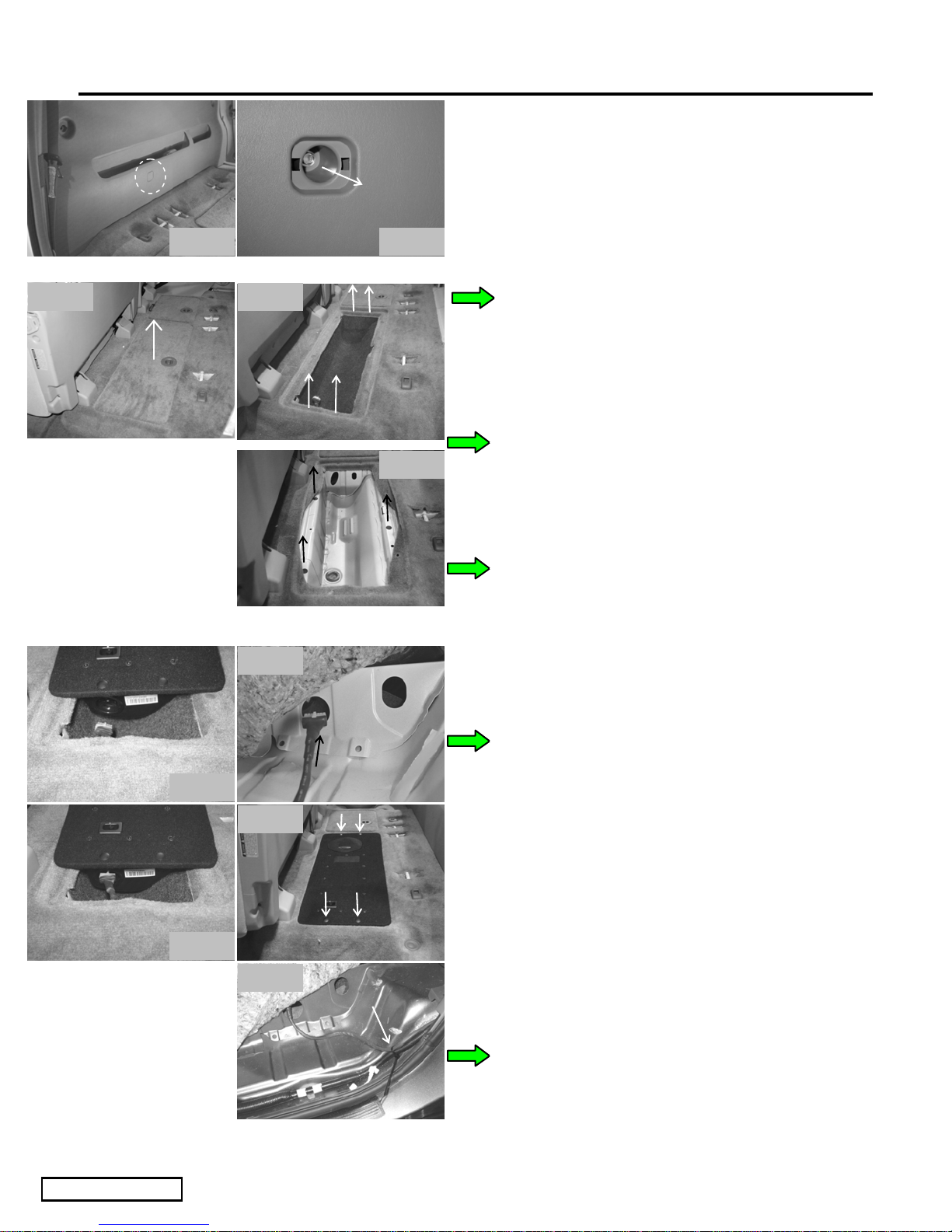
(2) Using an NRT, remove the bolt cover.
(Fig. 7c)
(3) Using a 10mm socket, remove the 10mm
bolt that attaches the cab panel. (Fig. 7d)
Fig. 7e
Fig. 7c
Fig. 7f
Fig. 8b
Fig. 7d
Fig. 7g
(4) Unsnap the cab panel from the cab and
remove from vehicle.
(5) There are a total of 17 clips attached to
the panel, in the event that any clips
remained attached to the vehicle, remove
them using an approved clip removal tool
and reinstall them to the panel.
(d) Remove & discard the rear driver side
storage well cover. (Fig. 7e)
(e) Remove the (4) side X-mas tree fasteners and
discard. (Fig. 7f)
(f) Remove storage well liner, (3) fasteners and
discard. (Fig. 7g)
8. Route Wire Harness
(a) Place the VSE over the storage well as
Fig. 8a
Fig. 8c
Fig. 8d
Fig. 8e
shown. (Fig. 8a)
(b) Route the wire harness through the large hole
on the outside of the storage well. (Fig. 8b)
(c) Plug wire harness connector into the
connector on the VSE. (Fig. 8c)
(d) Move the VSE toward the driver side.
(1) Pull the slack back through the hole.
(e) Align the 4 mounting clips on the VSE with
the mounting holes on the vehicle floor, and
apply pressure to the clips to securely fasten.
(Fig. 8d)
(f) Route the wire harness in the rear driver side
foot well and wire tie as shown. (Fig. 8e)
Issue: A 12/15/04
Page 4 of 12 pages
Page 5
TOYOTA TUNDRA D-CAB 2004 - VSE SUBWOOFER (NON-JBL)
Procedure
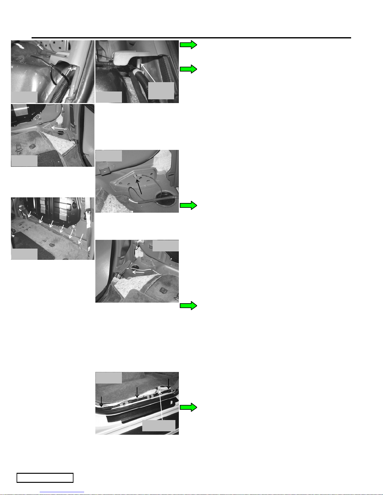
(g) Route wire harness along the factory harness
and wire tie as shown. (Fig. 8f & 8g)
(1) Start the wire tie outside the pillar cover
Fig. 8f
Fig. 8h
Fig. 8j
Fig. 8g
Fig. 8i
Harness
clip
Fig. 8k
and slide up the harness, tighten to the
existing harness clip and cut off excess.
(h) Remove rear corner of the rear carpet from
under the driver side pillar cover and route
the wire harness under the cover. (Fig. 8h)
(1) Tuck the carpet back under the pillar
cover.
(i) Using the supplier 10mm bolt, install the
ground ring onto the vehicle accommodated
weld nut. (Fig. 8i)
(1) Torque bolt to 10 lbf·ft
(j) Continue to route the wire harness under the
rear edge of the carpet. (Fig. 8j)
(k) Remove rear corner of the rear carpet from
under the passenger side pillar cover and
Fig. 8l
route the wire harness under the cover,
toward the passenger side rear door opening.
(Fig. 8k)
(1) Wire tie the wire harness to the vehicle
harness as described in step g-1.
(2) Tuck the carpet back under the pillar
cover.
(l) Route the wire harness along existing vehicle
harness in the rear door opening.
(1) Release the white plastic carpet clip and
route wire harness underneath. (Fig. 8l)
(2) Fasten to the vehicle harness using (3) 7”
wire ties as shown. Trim excess. (Fig. 8l)
Carpet clip
(m) Route wire harness behind the B-pillar cover
toward the front.
Issue: A 12/15/04
Page 5 of 12 pages
Page 6
TOYOTA TUNDRA D-CAB 2004 - VSE SUBWOOFER (NON-JBL)
Procedure
Fig. 8p
Fig. 8m
Under branch
Fig. 8o
Fig. 8q
Fig. 8n
Carpet clip
Wire tie
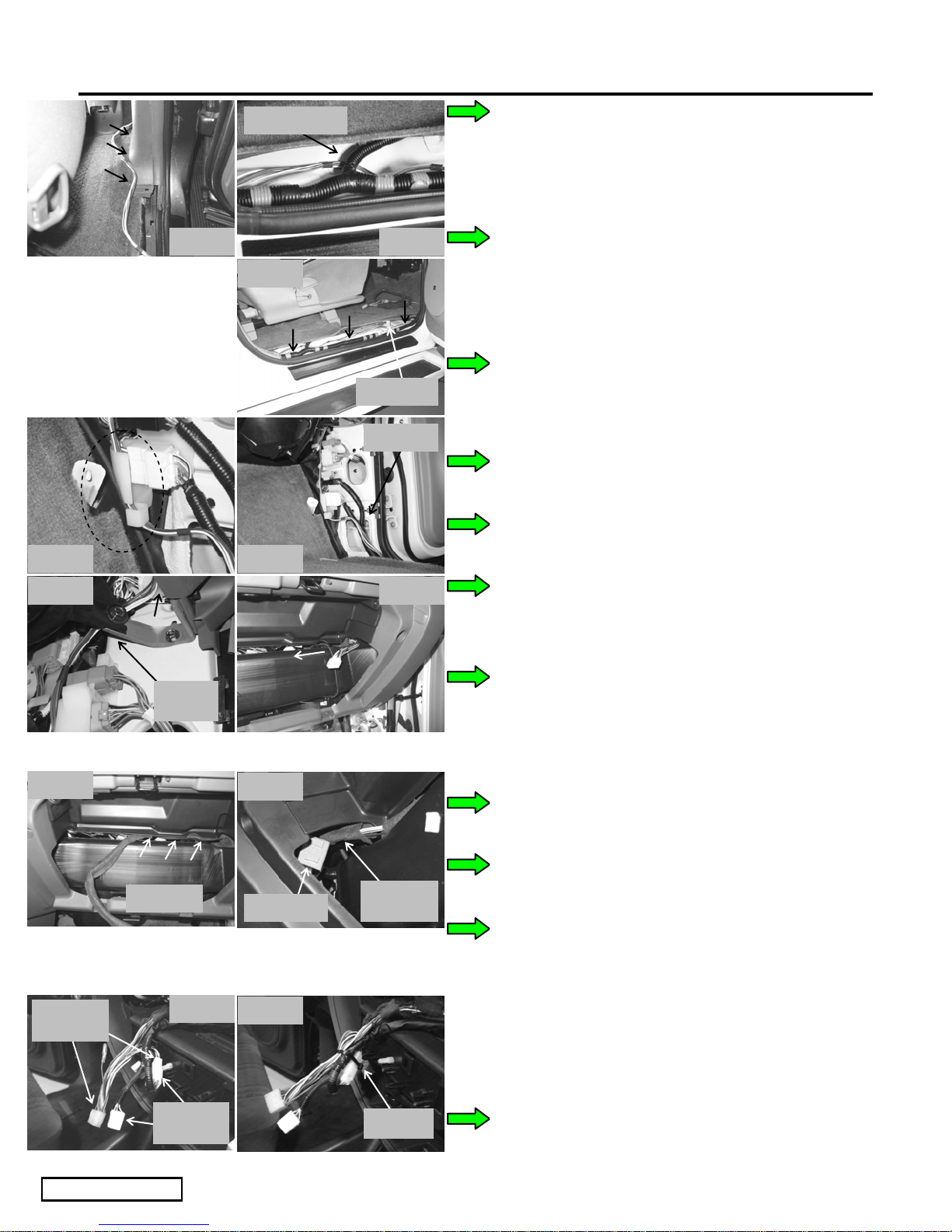
(1) Tuck the wire harness under the B-pillar
cover. (Fig. 8m)
(n) Route the wire harness along existing vehicle
harness in the front door opening.
(1) Route the harness under the “branch” in
the vehicle harness. (Fig. 8n)
(2) Release the white plastic carpet clip and
route wire harness underneath. (Fig. 8o)
(3) Fasten to the vehicle harness using (3) 7”
wire ties as shown. Trim excess. (Fig. 8o)
(o) Route wire harness up kick panel
(1) Insert wire harness into existing clip.
(Fig. 8p)
(2) Fasten to the vehicle harness using (1) 7”
wire tie as shown. Trim excess. (Fig. 8q)
Fig. 8r
Fig. 8t
VSE
connector
Behind
bracket
Tuck wire
Fig. 8v
Fig. 8u
Relay box
Relay box
Fig. 8w
Fig. 8s
Wire goes
over
(3) Route wire harness behind the dash
bracket, behind the duct and up toward
the glove box opening. (Fig. 8r)
(p) From the glove box opening, retrieve wire
from behind the duct. (Fig. 8s)
(1) Route the wire harness toward the radio
opening
(q) Tuck the wire harness between the HVAC
components. (Fig. 8t)
(r) Route the wire harness over the relay box.
(Fig. 8u)
(s) Continue to feed the harness under the duct
and toward the radio opening.
(t) Retrieve wire harness from bottom right
corner of radio opening.
Vehicle
connector
Issue: A 12/15/04
Wire tie
Page 6 of 12 pages
(u) Connect the wire harness to vehicle radio
harness. (Fig. 8v)
(v) Wire tie the harness assembly as shown.
(Fig. 8w)
Page 7
TOYOTA TUNDRA D-CAB 2004 - VSE SUBWOOFER (NON-JBL)
p
N
Procedure
Torque Wrench, 10mm Socket
egative Battery Cable
Fig. 8x
Factory cli
Wire tie
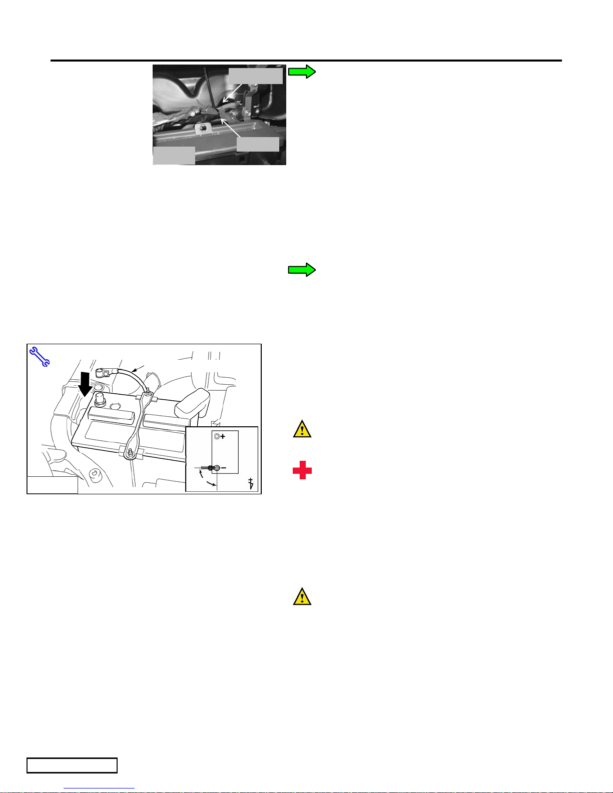
(w) Wire tie the harness to the factory harness
next to the brown factory wire tie clip.
(Fig. 8x)
9. In Process Functional Test.
(a) Reconnect the harness to the radio.
(1) Reconnect the Satellite radio harness if so
equipped
(2) Reconnect antennae cable.
(b) Reinstall radio.
(1) Be sure the wire harness is not pinched.
(c) Securely fasten (hand tighten) the four (4)
mounting fasteners using the 10mm socket.
DO NOT OVER TIGHTEN
(d) Reconnect the negative battery terminal.
(Fig. 9a)
Fig. 10-1
90˚
(1) Position the negative terminal at an angle
of 90˚ to the battery as shown.
(2) Tighten the nut with 4.1 N-m (36 lbf-in)
of torque.
(3) Be careful not to touch the positive
battery terminal.
(e) Turn ignition key to "ACC" position.
(f) Press the power button on the receiver/player
head unit. Verify the backlighting
illuminates.
(g) Verify that the green led on the VSE is
illuminated, and that sound is coming out of
the driver.
NOTE: If the green light on the VSE unit is
illuminated, and there is no sound coming from
the driver –then one (or more) of the four (4)
speaker wires are disconnected.
Issue: A 12/15/04
Page 7 of 12 pages
Page 8
TOYOTA TUNDRA D-CAB 2004 - VSE SUBWOOFER (NON-JBL)
Procedure
NOTE: If the green light on the VSE unit is
NOT illuminated – then the wire harness is not
properly connected to either the radio/amplifier,
or is not properly grounded.
10. Reassemble Interior
11. Test and Set Up Procedures
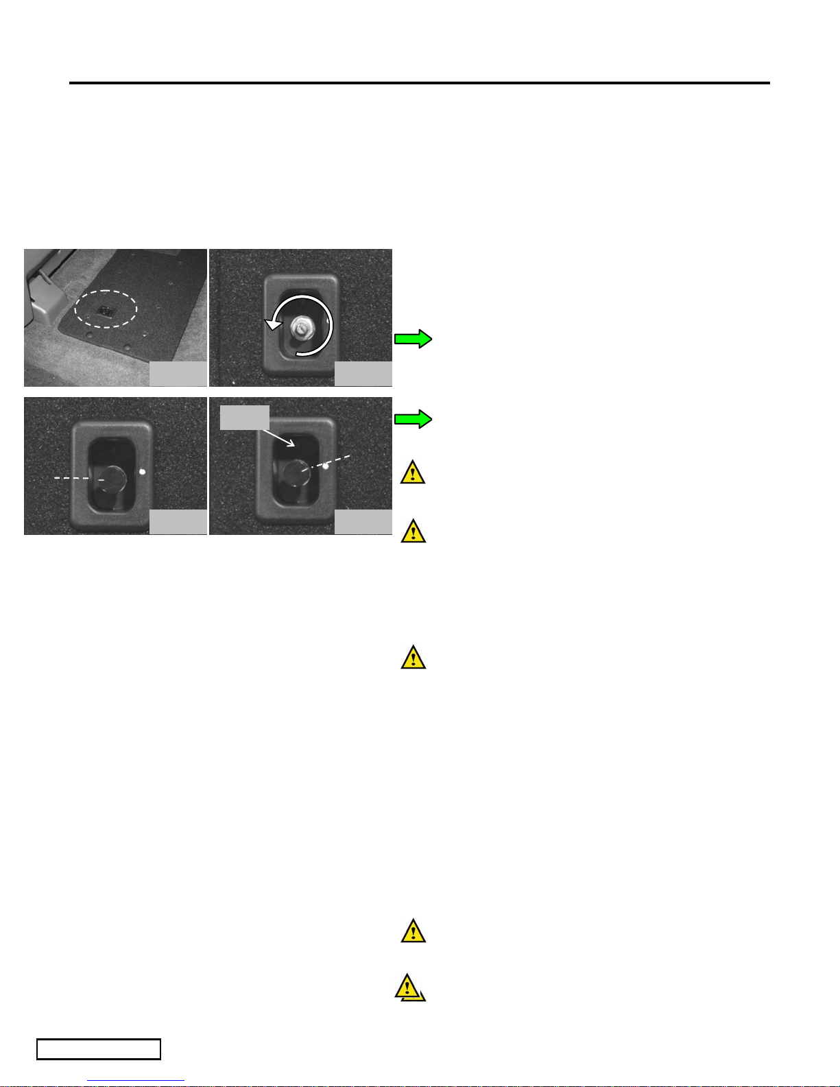
(a) Gain Control Knob Adjustment
(1) Remove gain control knob with needle
nose pliers. (Fig.11a)
(2) With a small slotted screwdriver, gently
Fig. 11a Fig. 11b
LED
Fig. 11c Fig. 11d
turn the gain control fully
counterclockwise. (Fig.11b)
(3) Re-install gain control knob with white
mark at 9:00. (Fig.11c)
(b) Match up white mark on gain control knob
with mark on enclosure. (Fig.11d)
(c) If system is installed correctly, the VSE
Subwoofer will power up when the vehicle’s
ignition is turned on. (indicated by
illumination of the POWER L.E.D. on the
Gain Control module of the unit.)
(d) Using the tone controls on the radio, adjust
the balance left and right, to verify that VSE
Subwoofer produces sound on both sides,
and that the sound is loudest when the
balance is set to the center.
Issue: A 12/15/04
12. Post Installation
(a) Clean up and remove any trash.
(b) If required, wipe down all applicable interior
surfaces with a plastic safe, VDC approved
cleaner. to remove fingerprints, etc
(c) Place Service Care Card in glove
compartment
(d) Hang Product Feature Placard onto the
rearview mirror.
Page 8 of 12 pages
Page 9
TOYOTA TUNDRA D-CAB 2004 - VSE SUBWOOFER (NON-JBL)
Checklist - these points MUST be checked to ensure a quality installation.
Check: Look For:
Accessory Function Checks
Turn on Radio
Verify CD & Satellite Tuner (if equipped)
Antenna is functioning
Bazooka Tube operation
Vehicle Function Checks
Hazard Button
Radio display turns on & sound is heard
CD player functions & Satellite Tuner
stations are playing (if equipped)
Reception of AM/FM stations
Bazooka Tube – Listen to Bazooka Tube to
make sure it is functioning properly or by
feeling the Bazooka for vibration. Be sure
the Phase Switch is in the “UP” position.
Functioning Hazard Lights
HVAC
Rear Window Defogger
Passenger Seat Belt Warning Light
All HVAC controls function properly
Functioning Rear Window Defogger
Functioning Seat Belt Warning Light
Issue: A 12/15/04
Page 9 of 12 pages
Page 10
TOYOTA TUNDRA D-CAB 2004 - VSE SUBWOOFER (NON-JBL)
Troubleshooting
Troubleshooting
Condition: Check For:
No sound from VSE Subwoofer, however
factory speakers still play
o Is the green L.E.D. lit on the VSE
Subwoofer? If not, check for 12 volts
on pins of the VSE Subwoofer with the
ignition on. If either pin doesn’t
indicate 12 volts, check T-Harness
connectors behind the radio.
o Is the 14-pin connector securely
connected to the VSE Subwoofer?
Distorted Sound
Low Sound
o Is the ground ring securely fastened to
the rear anchorage bolt?
o Fold down the rear seat.
o Adjust the radio to a comfortable
listening level, and then turn the “gain
control” knob on the VSE Subwoofer
counter-clockwise until the sound
becomes clean.
o Fold down the rear seat.
o Adjust the radio to a comfortable
listening level, and then turn the “gain
control” knob on the VSE Subwoofer
clockwise until the sound becomes
audible. Do not adjust the level too
high, as this will result in distorted
sound.
Rattling Noises
Issue: A 12/15/04
o Rattling will be evident in some panels
at extreme volume conditions, but make
sure you have performed the following
to minimize noise:
o Securely tightened Mounting Hardware
so VSE Subwoofer does not move.
Page 10 of 12 pages
Page 11
TOYOTA TUNDRA D-CAB 2004 - VSE SUBWOOFER (NON-JBL)
Troubleshooting
Troubleshooting
Condition: Check For:
Dimming Radio Lights
Radio does not come on
No Sound at all
VSE Subwoofer produces sound on the
right or the left, but not both.
o Dimming Radio Lights could occur when
the VSE Subwoofer is played at high
volumes.
o Check to ensure that the main connector,
antenna connector, and auxiliary connector
have been correctly plugged back in.
o Is the fuse under the hood still operational?
o Is the battery ground reconnected?
o Is the radio connector securely seated?
o Check T-Harness connections at the back of
the radio. All connectors must be securely
fastened to the correct wiring for both
channels to produce audio output.
Issue: A 12/15/04
Page 11 of 12 pages
Page 12
TOYOTA TUNDRA D-CAB 2004 - VSE SUBWOOFER (NON-JBL)
Troubleshooting
Troubleshooting
Condition: Check For:
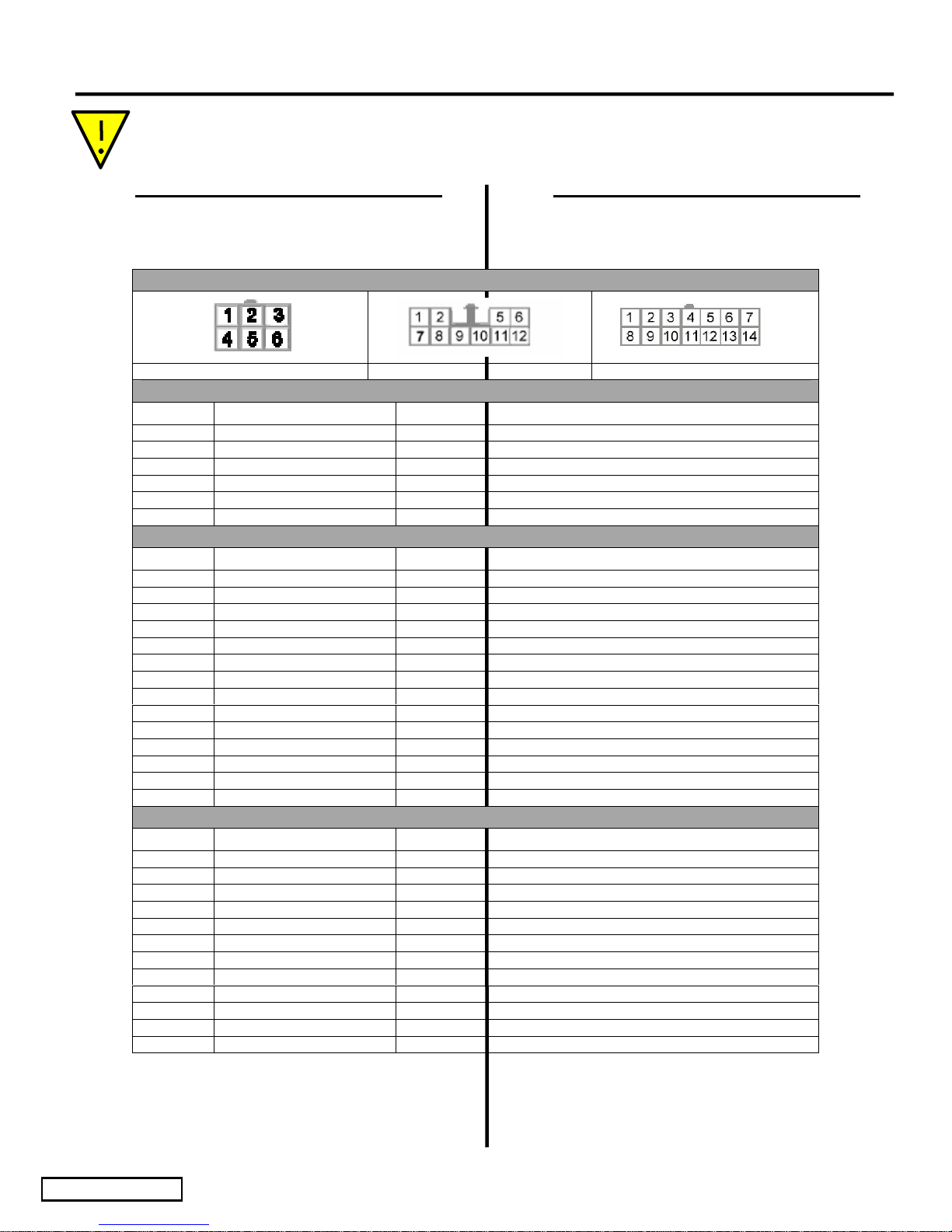
WIRING CONNECTOR SCHEMATICS:
Harness Split Radio Connector Subwoofer Connector
Pin No. Wire Color Function
1 Red 12 Volt Battery Connection (B+)
2 White/Black Left Front Speaker (-)
3 Gray/Black Right Front Speaker (-)
4 Blue/White Remote Turn-On/Ignition (Switched+)
5 White Left Front Speaker (+)
6 Gray Right Front Speaker (+)
Harness Split Connector
Subwoofer Connector
Pin No. Wire Color Function
1 Black Chassis Ground
2 N/A N/A
3 N/A N/A
4 N/A N/A
5 White Left Front Speaker (+)
6 Grey Right Front Speaker (+)
7 N/A N/A
8 Red 12 Volt Battery Connection (B+)
9 Blue/White Remote Turn-On/Ignition (Switched+)
10 N/A N/A
11 N/A N/A
12 White/Black Left Front Speaker (-)
13 Grey/Black Right Front Speaker (-)
14 N/A N/A
Radio Connector (R4 GRAY)
Pin No. Wire Color Function
1 Right Front Speaker (+)
2 Left Front Speaker (+)
3 NO CONNECTION NO CONNECTION
4 NO CONNECTION NO CONNECTION
5 12 Volt Ignition Switched (B+)
6 12 Volt Battery Connection (B+)
7 Right Front Speaker (-)
8 Left Front Speaker (-)
9 Chassis Ground (B-)
10 Power Antenna Control (+)
11 Power Antenna Control (-)
12
Dimmer / Illumination Control (B+ variable)
Issue: A 12/15/04
Page 12 of 12 pages
 Loading...