

Page 1

DS Series Manual
DATA SWITCH
DS74 Serial Input - Output Module
BayTech Manual Publication
Revision May 2008
Page 2

DS74 Serial I/O Module
Copyright 2007 by Bay Technical Associates, Inc.
BayTech, is a registered trademarks of Bay Technical Associates, Inc.
Windows 2000®, Windows XP® are products and registered trademark of Microsoft Corporation.
Tera Term is a product and registered trademark of Vector, Inc.
2
Page 3

DS74 Serial I/O Module
Cabling............................................................................................................................................................4
RJ-45 Cables and Adapters......................................................................................................................... 4
Adapters ......................................................................................................................................................5
Serial Setup.................................................................................................................................................5
Unit Configuration Menu.................................................................................................................................. 6
DS74 Configuration Menu...............................................................................................................................6
Status...........................................................................................................................................................7
Serial Port Configuration.............................................................................................................................. 7
Handshaking............................................................................................................................................7
Baud Rate................................................................................................................................................8
Word Size.................................................................................................................................................9
Stop Bits...................................................................................................................................................9
Parity........................................................................................................................................................ 9
RTS/DTR Line Driver Inactivity State.....................................................................................................10
Port Device Name...................................................................................................................................... 10
Port Device Type.......................................................................................................................................11
Verify DS74 is functioning:............................................................................................................................12
RESET DS74 Configuration.......................................................................................................................... 12
BayTech Product Warranty...........................................................................................................................13
Technical Support......................................................................................................................................14
Return Authorization Process:................................................................................................................... 15
3
Page 4
DS74 Serial I/O Module
Cabling
RJ-45 Cables and Adapters
DS74 EIA-232 RJ-45 Signal
Pin EIA 232
Signal
1 DTR Out
2 GND Signal Ground
3 RTS Out
4 TX Out Transmit Data Out
5 RX In Receive Data In
6 DSR In
7 GND
8 CTS In
Adapters Signals
Listed are the pin
Signal
Direction
Handshake, Line Driver Inactive State = Low: -12V when port is selected
unless programmed differently. Used as a handshake line to enable/disable
the receiving of characters.
Handshake, Line Driver Inactive State = Low: -12 V when port is selected
unless programmed differently.
Handshake In. +12V when not used.
Signal Ground
Used as a handshake line to enable/disable the receiving of characters.
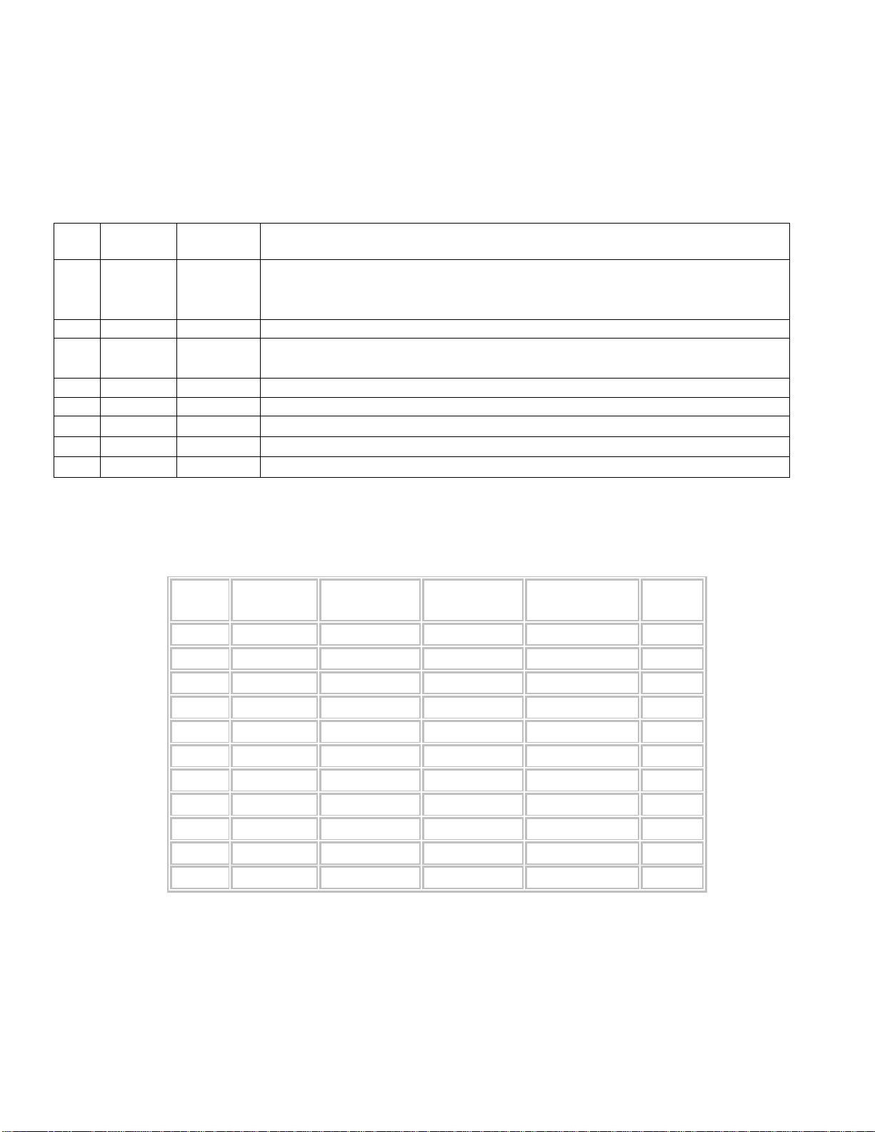
specifications for the BayTech cable and adapters and the terminal COM ports:
Description
Signal RS-232
Port (DS)
RS-232
Port (RPC)
COM Port
DE-9 Pin
COM Port
DB-25 Pin
Signal
DTR 1 1 4 20 DSR
GND 2 2 1 GND
RTS 3 3 7 5 CTS
TXD 4 4 3 2 RXD
RXD 5 5 2 3 TXD
DSR 6 N/C 6 6 DTR
GND 7 7 5 7 GND
CTS 8 8 4 RTS
DTR 4 DCD
DCD 8 1 8 DTR
RI 9 22
4
Page 5
Adapters
DS74 Serial I/O Module
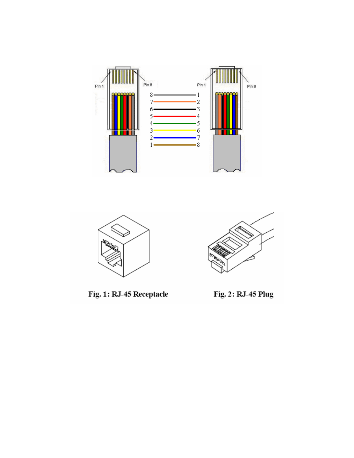
RJ08X007
Figures 1 and 2 provide visual representation of an RJ-45 receptacle and plug.
Serial Setup
• Connect the EIA-232 port to a Baytech device via the RJ08X007 rolled flat ribbon cable.
• Baytech makes custom cables for some devices.
• Default configuration is 9600 bps, 8 data bits, 1 stop bit and no parity.
5
Page 6

DS74 Serial I/O Module
Unit Configuration Menu
The configuration menu allows the user to choose which unit they would like to access. Enter the number
that corresponds with the Host Module followed by a <cr>. Now the module can be configured as shown.
This menu is where you will be able to edit any of the information listed below. The following pages define
each line of the configuration menu.
Configuration
DS62 module #1..........1
DS74 module #2..........2
DS-RPC module #5..........3
Enter Request :
NOTE: The DS74 I/O peripheral configuration is save to the host module.
DS74 Configuration Menu
Copyright(C) Bay Technical Associates 2005
Data Switch Series - EIA-232 I/O Module
Module 2
Status..........................1
Serial Port Configuration.......2
Port Device Name................3
Port Device Type................4
Exit............................X,CR
Enter Request :
IMPORTANT: Once you make a change to any of the Configuration options, you have to back out
of the Configuration menu and will be asked to ‘Accept changes’. If you type ‘Y’ for YES, the
changes take effect immediately for the serial port.
Accept changes ? (Y/N) :y
Changes accepted.
6
Page 7

DS74 Serial I/O Module
Status
Displays the current configuration of each I/O port.
+----+------+-----------------+------+------+------+------+---------+----+----+
|Port|Device| Device | Baud | Word | Stop |Parity|Handshake|LineDrive|
| | Type | Name | Rate | Size | Bits | | |DTR |RTS |
+----+------+-----------------+------+------+------+------+---------+----+----+
| 1 | RPC | Device A | 9600 | 8 | 1 | None | None | HI | HI |
+----+------+-----------------+------+------+------+------+---------+----+----+
| 2 | RS232| Device B | 9600 | 8 | 1 | None | None | HI | HI |
+----+------+-----------------+------+------+------+------+---------+----+----+
| 3 | RS232| Device C | 9600 | 8 | 1 | None | None | HI | HI |
+----+------+-----------------+------+------+------+------+---------+----+----+
| 4 | RS232| Device D | 9600 | 8 | 1 | None | None | HI | HI |
+----+------+-----------------+------+------+------+------+---------+----+----+
Strike ENTER to continue
Serial Port Configuration
Since the DS74 I/O modules use different serial port configurations. Handshaking, Baud Rate, Word Size,
Stop Bits, and Parity can all be configured through the HOST module using the menus. The default settings
are 9600bps, 8 data bits, no parity, one stop bit, RTS and DTR High.
Select 2), the peripheral module responds asking for a port number:
Enter Serial Port Number (? = Help, ENTER = Exit) :1
Type the port number, press <cr> and the unit responds:
+----+------+-----------------+------+------+------+------+---------+----+----+
|Port|Device| Device | Baud | Word | Stop |Parity|Handshake|LineDrive|
| | Type | Name | Rate | Size | Bits | | |DTR |RTS |
+----+------+-----------------+------+------+------+------+---------+----+----+
| 1 | RS232| Device A | 9600 | 8 | 1 | None | None | HI | HI |
+----+------+-----------------+------+------+------+------+---------+----+----+
Handshaking......................1
Baud Rate........................2
Word Size........................3
Stop Bits........................4
Parity...........................5
RTS Line Driver Inactive State...6
DTR Line Driver Inactive State...7
Enter Request :1
Handshaking
For a simple communication between modems three connected lines are needed: TX, Rx, and Ground. For
the data to be transmitted, both sides have to be clocking the data at the same baud rate. While this method is
sufficient for most applications, it is limited in being able to respond to problems such as the receiver getting
overloaded. This is where serial handshaking can help.
Select 1), for the Handshaking menu, Default is None, the Host module responds with the following:
7
Page 8

DS74 Serial I/O Module
Select handshaking:
1 For None
2 For Software Handshaking
3 For Hardware Handshaking
Enter Request :
Type a number to select the handshaking option and press <cr>.
1. Software Handshaking: This style uses actual data bytes as control characters. The lines necessary
are TX, Rx, and ground since the control characters are sent over the transmission line like regular
data. The two control characters, XON and XOFF are characters sent by the receiver of the data to
halt the transmitter during communication.
NOTE: A drawback to this method is also the most important fact to keep in mind. In ASCII
transmissions these character values are non-character values; however, data being transmitted via
binary, it is very likely that these values could be transmitted as data and the transmission would fail.
2.
Hardware Handshaking: This style uses actual hardware lines. Like the TX and Rx lines, the
RTS/CTS and DTR/DSR lines work together. When a receiver is ready for data, it will assert the RTS
(Request to Send) line. This is then read by the sender at the CTS (Clear to Send) input, indicating it
is clear to send the data. DTR (Data Terminal Ready) and DSR (Data Set Ready) allow the serial port
and the modem to communicate their status. When the modem is ready for data to be sent, it will
assert the DTR line indicating that a connection has been made across the phone line. This is read in
through the DSR line and the modem can begin to send data. The general rule of thumb is that the
DTR/DSR lines are used to indicate that the system is ready for communication where the RTS/CTS
lines are used for individual packets of data.
Baud Rate
Select 2), Baud Rate is the rate the modem transfers Data bites per second, Default is 9600, the Host module
responds:
Type a number to select the Baud Rate and press <cr>.
Select baud rate:
1 For 300
2 For 600
3 For 1200
4 For 2400
5 For 4800
6 For 9600
7 For 19200
8 For 38400
9 For 57.6K
A For 76.8K
B For 115.2K
Enter Request :
8
Page 9

DS74 Serial I/O Module
Word Size
The word size is the measurement of the actual data bits in a transmission. Which setting you choose
depends on what information you are transferring. For example, standard ASCII has values from 0 to 127 (7
bits). Extended ASCII uses 0 to 255 (8 bits). If the data being transferred is simple text (standard ASCII),
sending 7 bits of data per packet is sufficient for communication. A packet refers to a single byte transfer,
including start/stop bits, data bits, and parity.
Select 3), to get the Word Size, Default is 8 the Host module responds:
Select word size:
1 For 5
2 For 6
3 For 7
4 For 8
Enter Request :
Type a number to select the Word Size and press <cr>.
Stop Bits
The Stop Bits are used to signal the end of communication for a single packet. Since the data is clocked
across the lines and each device has its own clock, it is possible for the two devices to become slightly out of
sync. Therefore, the stop bits not only indicate the end of transmission but also give the computers some
room for error in the clock speeds. The more bits that are used for stop bits, the greater the lenience in
synchronizing the different clocks, but the slower the data transmission rate.
Select 4), to get the Stop Bits, Default is 1 the Host module responds:
Select stop bits:
1 For 1
2 For 1.5
3 For 2
Enter Request :
Type a number to select the Stop Bits option and press <cr>.
Parity
Parity is a simple form of error checking used in serial communication. For even and odd parity, the serial
port will set the parity bit (the last bit after the data bits) to a value to ensure that the transmission has an
even or odd number of logic high bits. For example, if the data was 011, then for even parity, the parity bit
would be 0 to keep the number of logic high bits even. If the parity was odd, then the parity bit would be 1,
resulting in 3 logic high bits. This allows the receiving device to know the state of a bit so as to enable the
device to determine if noise is corrupting the data or if the transmitting and receiving devices' clocks are out
of sync.
With no parity selected (or defaulted), it's assumed that there are other forms of checking that will detect any
errors in transmission. No parity also usually means that the parity bit can be used for data, speeding up
transmission. In modem-to-modem communication, the type of parity is coordinated by the sending and
receiving modems before the transmission takes place.
9
Page 10

DS74 Serial I/O Module
Select 5), to get the Parity, Default is None the Host module responds:
Select parity:
1 For None
2 For Even
3 For Odd
Enter Request :
Type a number to select the Parity option and press <cr>.
RTS/DTR Line Driver Inactivity State
RTS (Request to Send)/ DTR (Data Terminal Ready) is normally used in conjunction with an external
modem. With no modem the RTS and DTS default state is High.
Select 6), from the Serial Port Configuration the Host Module responds:
RTS Line Driver Inactive State is: High
High ? (Y/N, CR for no change):
Select 7), from the Serial Port Configuration the Host Module responds:
DTR Line Driver Inactive State is: High
High ? (Y/N, CR for no change):
Type ‘Y’ for YES or ‘N’ for NO and press <cr>.
NOTE: Once you make a change to the Serial Port Configuration options, you have to back out of
the menu and will be asked to Accept changes. If you type ‘y’ for yes, the changes take effect
immediately for the serial port.
Accept changes ? (Y/N) :y
Type ‘Y’ for YES or ‘N’ for NO and press <cr>.
Changes accepted.
Port Device Name
Select the port you want to rename, followed by a <cr>. Type the name you want to identify the port.
Enter Serial Port Number (? = Help, ENTER = Exit) :1
The unit displays the current port configuration.
10
Page 11

DS74 Serial I/O Module
+----+------+-----------------+------+------+------+------+---------+----+----+
|Port|Device| Device | Baud | Word | Stop |Parity|Handshake|LineDrive|
| | Type | Name | Rate | Size | Bits | | |DTR |RTS |
+----+------+-----------------+------+------+------+------+---------+----+----+
| 1 | RS232| Device A | 9600 | 8 | 1 | None | None | HI | HI |
+----+------+-----------------+------+------+------+------+---------+----+----+
Enter Port Device Name (Max. 16 characters):
or press ENTER for no change .....:test
NOTE: Once you make a change to the Port Device Name, you have to back out of the menu and
will be asked to Accept changes. If you type ‘y’ for yes, the changes take effect immediately for the
serial port.
Accept changes ? (Y/N) :y
Type ‘Y’ for YES or ‘N’ for NO and press <cr>.
Changes accepted.
Port Device Type
There are two configurations of port types. The standard RS-232 is the basic configuration for transfer of
data. RPC-SNMP is allows the port to be monitored through SNMP protocol. The host module will poll the
port at a predetermined time based on the firmware and displays the RPC/RPS SNMP ID data from the unit
connect to the port on the host main menu. Default is RS-232 Type
NOTE: If no RPC/RPS with SNMP enabled device is connected to the port, the host module will
wait approximately 40 seconds for the port to respond to it’s polling upon power up or host module
Select the port you want to change the TYPE, followed by a <cr>.
The unit responds with the port’s current type.
unit reset and display the following: No communication with RPC at Module # Port #
Enter Serial Port Number (? = Help, ENTER = Exit) :1
Module 2, Port 1 device type: RS232
Note: Changing port type will force a unit reset when configuration is exited
RS-232..........................1
RPC-SNMP........................2
Exit............................X,CR
Enter Request :2
Selecting either option the module responds with the DS74 Configuration Menu.
NOTE: Once you make a change to the port type, you have to back out of the Port Type menu and
will be asked to Accept changes. If you type ‘Y’ for YES, the changes take effect immediately for the
serial port.
Accept changes ? (Y/N) :y
11
Page 12

DS74 Serial I/O Module
Type ‘Y’ for YES or ‘N’ for NO and press <cr>.
Changes accepted.
Verify DS74 is functioning:
A rollover cables (pin out 1-8, 2-7, 3-6, 4-5, 5-4, 6-3, 7-2, 8-1) and a 9-pin adapter (9FRJ45PC-1) and
Ethernet or Modem cable.
1. Set up the Host module with modem or Ethernet cables for normal operations.
2. Connect the rollover cable and adapter from the PC to a DS74 port.
3. Create a Modem/Ethernet session. (i.e. Hyper-terminal) Type semi-colon 5-times (; ; ; ; ;) Press
‘Enter’ until you get to the main menu.
4. The main menu should display the DS74 ports. Select the port connected to the PC from step 2. The
cursor will move to next line and wait.
5. From your PC create a terminal session to the serial port. Default setting is 9600, 8, 1, no parity, no
flow.
6. Type several random characters to see them echoed in the telnet/modem session.
7. Select the telnet/modem session and type several random characters to see them echoed in the PC
serial session.
8. This verifies the Chassis, Host module, and the I/O port is working.
9. Move pc cable to next DS74 port and repeat step 3 -9.
If a DS74 module appears not to be working, move the module to a different slot and retest.
RESET DS74 Configuration
1. Perform a host module Factory Default reset procedure.
2. Select the DS74 module in the Configuration Menu; select Serial Port Configuration; select each
option and change to default setting, 9600bps, 8 data bits, no parity, one stop bit, RTS and DTR
High.
12
Page 13

DS74 Serial I/O Module
BayTech Product Warranty
Bay Technical Associates (BayTech) warrants that its products will be free from defects in materials and
workmanship under normal use for a period of two years from date of purchase (or from date of shipment
from BayTech if proof of purchase is not provided).
During this warranty period, BayTech shall, at its discretion, either repair or exchange any defective product
at no charge for labor and materials, or refund the amount paid for the product, less shipping and handling
charges. Any replacement and/or repaired products are warranted for the remainder of the original warranty.
The customer is responsible for properly packaging the product and for shipping costs for returns. The
customer is liable for loss or damage to the product during shipping, as well as any other fees or charges
associated with transporting the product back to BayTech. BayTech will pay return costs for delivery within
the Continental United States.
All repair and return shipments must be approved by BayTech and must be accompanied by an RA (return
authorization) number. Please refer to our Repair and Return Policy below.
For the initial 30 days from the original date of shipment, any unopened product may be returned to
BayTech, accompanied by an RA number. Full purchase price will be refunded, provided that the product is
in excellent condition. A product may not be returned after 30 days from the original date of shipment unless
approved by BayTech management.
Replacements for defective products may be cross-shipped to the customer at no cost if requested within 30
days of date of purchase. At BayTech’s discretion, this period may be extended to 90 days.
For additional information or more specific warranty issues, contact BayTech’s Technical Support
Department at (800) 523-2702 or (228) 563-7334.
Exceptions
This warranty does not cover misuse or minor imperfections that fall within design specifications or that do
not materially alter functionality. BayTech does not warrant and is not responsible for damages incurred in
shipping and handling or caused by disasters (such as fire, flood, wind, earthquake, lightning, power surges
or water).
The warranty will be voided regarding products that have been neglected, altered, abused, misused, or used
for purposes other than those for which it was designed.
Under no circumstances shall BayTech be liable for any special, incidental, or consequential damages based
upon breach of warranty, breach of contract, negligence, strict liability, or any other legal theory. Such
damages include (but are not limited to) loss of profits, loss of the product or associated equipment, cost of
capital, cost of substitute or replacement equipment, facilities or services, down time, purchaser’s time, the
claims of third parties, including customers, and injury to property.
BayTech Extended Warranty
Extended warranties and overnight replacements are available for purchase, but only at the time of product
purchase. The extended warranty cost will not exceed 7% per year of the product list price unless otherwise
stated in the customer contract or approved by BayTech management. Contact BayTech for further details on
this.
13
Page 14

DS74 Serial I/O Module
Technical Support
BayTech offers Tech Support for the lifetime of the product. A staff of Applications Engineers is on duty to
assist with installation, set up or operation issues. Support is available from 8:00 a.m. to 5 p.m. (CST or
CDT), Monday through Friday at the phone numbers or website provided below.
Please have the following information available to help the Applications Engineers answer questions
efficiently:
1. BayTech model type
2. Unit serial number
3. Firmware version (if accessible)
4. A list of devices connected to the BayTech unit
5. A general description of the application being used and the intended outcome
6. Information about cables and adapters being used (type, length, place of purchase)
7. The name of the software emulation program being used
8. Printout of the configuration status (if possible)
Bay Technical Associates, Inc.
5239 A Avenue
Long Beach Industrial Park
Long Beach, MS 39560
Telephone: 800-523-2702 or 228.563.7334
FAX: 228.563.7335
Email: support@baytech.net
Website: www.baytech.net
Repair and Return Policy
(Return policy refers to BayTech products purchased and returned for credit or repair.)
A Return Authorization (RA) number must be obtained in all cases before returning the BayTech product.
Have the serial number and reason for the return or description of the problem handy. Customers in the
Continental U.S. can call 1-800-523-2702 or international customers can call 228.563.7334 to obtain an RA
number.
If a product is being returned for credit (based on BayTech approval), the credit will not include shipping and
handling charges. Determination of credit amount will be made after BayTech receives the product.
Returns on BayTech products older than 3 months are subject to a 15% re-stocking fee of the list price of the
product and will be evaluated on a case-by-case basis. BayTech does not allow returns on products out of
warranty or for any type of custom product.
Before dismantling equipment or returning the unit for any reason, always contact BayTech. Attempting to
repair a product without BayTech authorization may result in voiding the warranty.
Follow the instructions below for repackaging and shipping. NOTE:
power source before servicing or dismantling.
Power should be disconnected from the
14
Page 15

DS74 Serial I/O Module
Return Authorization Process:
1. Contact BayTech to get a Return Authorization (RA) Number. IMPORTANT: BayTech will not
accept any returns without an RA number.
2. Package the unit carefully in its original packaging or similar packaging. The warranty does not cover
damage sustained during shipment. Enclose a letter with name, address, RA number, daytime phone
number and description of the problem.
3. Mark the RA number clearly on the outside of the package.
NOTE: If the RA number is not on the outside of the box, the package will be returned back to the
sender or will sit in Receiving until the customer calls in regarding status of RA.
4. Ship the unit by insured, prepaid carrier to the following address:
Bay Technical Associates
5239 A Avenue
Long Beach Industrial Park
Long Beach, MS 39560
5. Surround your unit with a minimum of two inches of insulation.
6. Be sure to seal the box securely with strapping or packing tape. We do not recommend masking tape
or cellophane tape.
RA #: 140-xxxxx
15
 Loading...