

Page 1
OWNER'S MANUAL
________________
DS72 NETWORK INTERFACE MODULE
FOR DS SERIES AND DS-RPC PRODUCTS
BayTech Manual Publication #
October 1998
U140A127
Page 2

Copyright 1998 by Bay Technical Associates, Inc.
BayTech is a registered trademark of Bay Technical Associates, Inc.
IBM, IBM PC, IBM PC/AT, IBM PC/XT are products and registered trademarks of
International Business Machines Corporation.
Windows 95
is a product and registered trademark of M icrosoft Corpor ation.
ii
Page 3

DS72 HOST MODULE OWNER’S MANUAL
ABOUT THIS OWNER’S MANUAL
ABOUT THIS OWNER’S MANUAL
This document provides information required for installing and operating your Bay Tech equipment. It
should allow the user to connect, power up, and access an applications menu where peripheral
equipment can be controlled. We recommend reading this manual carefully, while placing special
emphasis on correct cabling and configuration. If you have any problems w ith your installation, please
contact a BayTech Applications Engineer at
States using
1-800-523-2702
or contact us at our We b Sit e , www.baytechdcd.com.
BayTech manufactures many remote site management products, data switches, data collection
mult iple xers, r emot e power contro llers, and per ipher al print shar ers. I f you wo uld like infor mation o n
any of these products, please contact BayTech Customer Service at the numbers pr eviou sly listed.
Conv e nt io n s use d in th is ma nu a l inc lu d e:
228-467-8231
, call toll free from anywhere in the United
CAUTION:
This term is used to denote any condition that could possibly result in physical
harm to personnel or damage to equipment.
IMPORTANT:
This term is used to denote conditions that could result in the loss of
communications or to highlight the proper functioning of equipment.
NOTE:
<cr>:
This term is used to denote items of interest to the user.
Carriage Return or ENTER
The information in this document is subject to change without notice. The statements, configurations,
technical data, and recommendations in this document are believed to be accurate and reliable, but are
presented without express o r implied warrant y. Users must t ake full respo nsibility for the ir applications
of any products specified in this document. The information in this document is proprietary to Bay
Technical Associates, Inc.
In the interest of improving internal design, operational function, and/or reliability, Bay Technical
Associates, Inc reserves the right to make changes to the products descr ibed in this document without
notice.
Bay Technical Associates, Inc does not assu me any liability t hat may occur due to the use or application
of the product(s) or circuit layout(s) described herein.
We welcome any comments you may have about our products, and we hope that you will continue to
look to BayTech for your dat a communication needs.
iii
Page 4

TABLE OF CONTENTS
ABOUT THIS OWNER’S MANUAL................................................................................iii
INTRODUCTION TO THE DS72 NETWORK INTERFACE MODULE ................... 1
PROGRAMMABLE FEATURES OF THE DS72 ............................................................................................................1
DS72 QUICK START............................................................................................................ 3
EIA-232 SERIAL CONNECTION...................................................................................................................................3
INSTALLATION................................................................................................................... 5
UNPACKING..................................................................................................................................................................5
PREPARING THE INSTALLATION SITE.....................................................................................................................5
POWER ...........................................................................................................................................................................5
CABLING ............................................................................................................................... 6
RJ-45 CABLES AND ADAPTERS..................................................................................................................................6
DETAILED OPERATION AND CONFIGURATION..................................................... 8
ACCESSING MAIN MENU............................................................................................................................................8
SELECTING A DEVICE.................................................................................................................................................8
CONFIGURATION.......................................................................................................................................................10
STATUS....................................................................................................................................................................10
SERIAL PORT CONFIGURATION .......................................................................................................................... 11
PORT DEVICE NAME..............................................................................................................................................12
PORT SEL ECT CODE ...............................................................................................................................................13
ATTENTION CHARACTER.....................................................................................................................................14
DISCONNECT TIME GUARD.................................................................................................................................. 14
CONNECT PORT ID ECHO......................................................................................................................................14
LOGIN SETUP..........................................................................................................................................................15
HEADER...............................................................................................................................................................15
PASSWORD ..........................................................................................................................................................16
MENU....................................................................................................................................................................16
AUTO C ONNEC T PO RT.............................................................................................................. ..........................17
NETWORK PORT CONFIGURATION..................................................................................................................... 18
MODULE IP ADDRESS........................................................................................................................................ 18
SUBNET MASK....................................................................................................................................................19
GATEWAY...........................................................................................................................................................19
ACTIVITY TIMEO UT...........................................................................................................................................20
CARRIAGE RETURN TRANSLATION ................................................................................................................20
BREAK LENGTH..................................................................................................................................................20
UNIT ID....................................................................................................................................................................20
STATUS........................................................................................................................................................................21
SYSTEM...................................................................................................................................................................21
NETWORK...............................................................................................................................................................21
LOGGED USERS......................................................................................................................................................21
I/O MODULES RESET .................................................................................................................................................21
UNIT RESET................................................................................................................................................................21
DIAGNOSTICS.............................................................................................................................................................22
TECHNICAL SUPPORT.................................................................................................... 23
iv
Page 5

TABLE OF CONTENTS
REPACKAGING, SHIPPING AND RETURNING TO THE FACTORY.................. 24
FCC RADIO FREQUENCY INTERFACE STATEMENT........................................... 25
APPENDIX A: SPECIFICATIONS..................................................................................26
APPENDIX B: OPERATING WITH A MODEM ..........................................................27
INDEX ................................................................................................................................... 29
v
Page 6
DS72 HOST MODULE OWNER’S MANUAL
INTRODUCTION TO THE DS72 HOST MODULE
INTRODUCTION TO THE DS72 NETWORK INTERFACE
MODULE
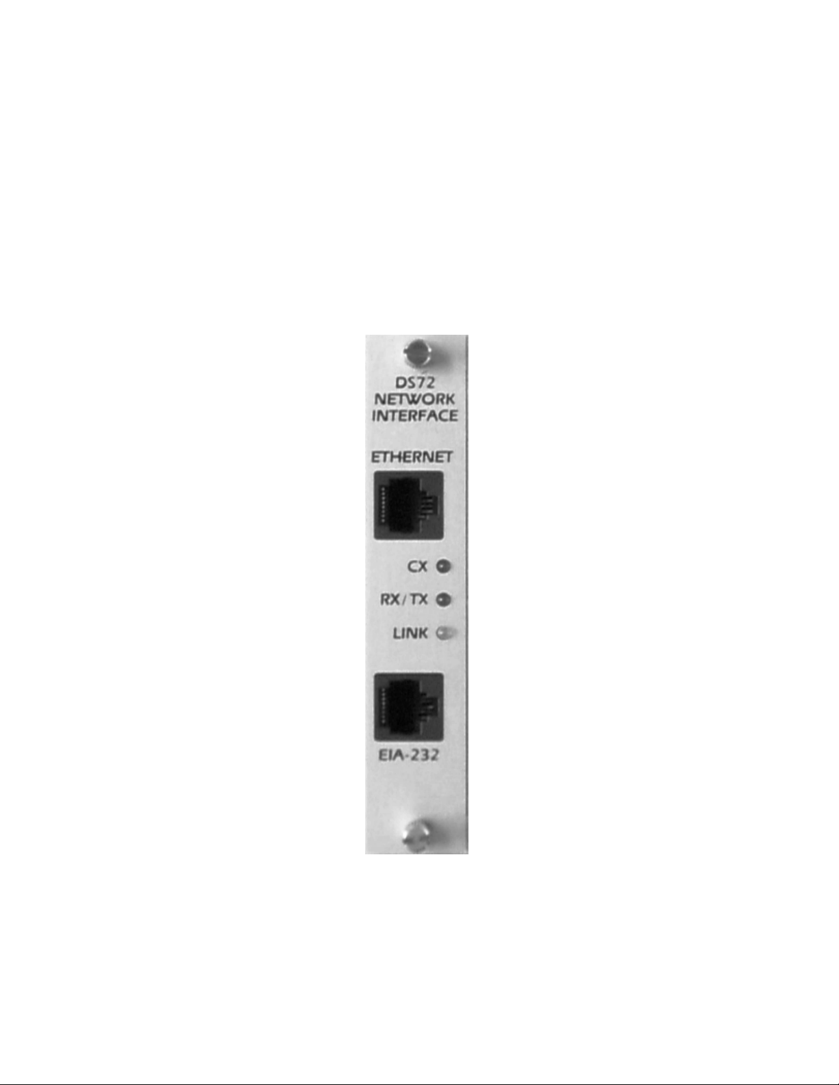
The DS72 network interface module is a primary user interface for use with the BayTech DS-Series and
DS-RPC units. The DS72 allows network users operating on a device using a TCP/IP stack with an
ethernet connect ion, to access the main DS units, serial I/O modules, and (in the case o f the DS-RP C)
remote power switches. It also allows remote access via external modem to the serial port. This makes the
DS72 an extremely versatile module, covering most applications.
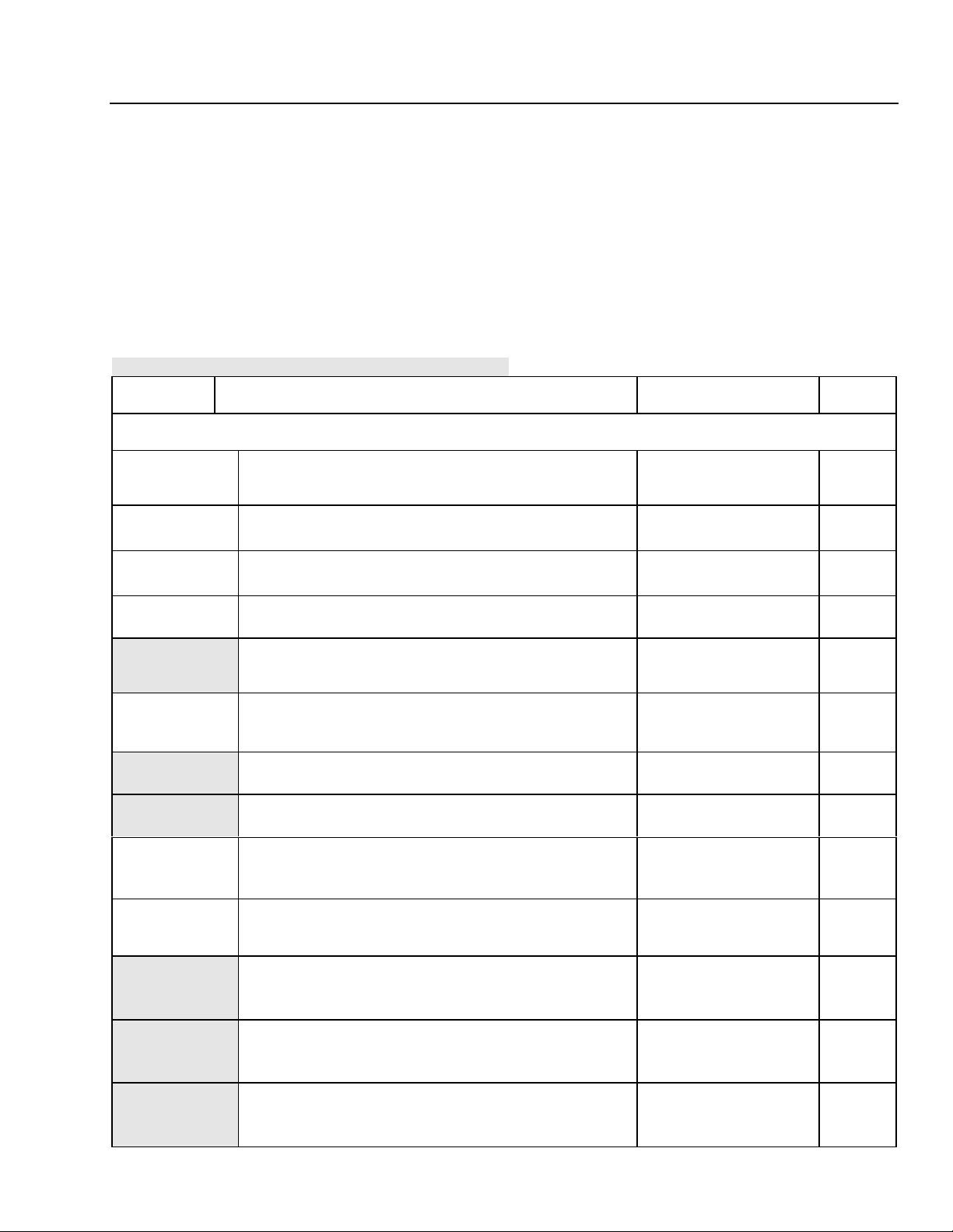
PROGRAMMABLE FEATURES OF THE DS72
Highlighted features indicate items most often programmed
FEATURE DESCRIPTION ACTION PAGE
NO.
DS72 N
ETWORK INTERFACE MODULE
Serial Port
Configuration
Port Device
Name
Port Select Code ASCII character string used to select a port or module.
Attention
Character
Disconnect Time
Guard
Port ID Echo Echoes the module number and port number when you
Header Unit information that appears upon login
Password Password protection for telnet and EIA-232 connections.
Menu Provides a menu interface for device selection, and
Auto Connect
Port
IP Address IP Address for the DS72 to access the network.
Sets serial port speed of the DS72 Default = 9600, 8, 1, N,
Xon/Xoff Disabled
Uniquely identifies the port (or device connected to the port).
Default = Host EIA-232
Default = $BT
A character sent in sequence five times to invoke the main
menu. De fault = ;
Provides reliable bin ary data transmission. Defaul t =
Disabled
conn ect to the port .
Default = Disabled
Default = DS72
Default = Disabled
configuration.
Default = Enabled
Allows automatic connection to a specified port upon Telnet
or EIA-232 connection.
Default = Disabled
Default = 0.0.0.0
Enter baud rate, data bits,
stop bits, parity, and
Xon/Xoff
Enter the device na me 12
Enter Port Select Code 13
Enter Attention Character 14
Enable/Disable
Disconnect Time Guard
Enable/Disable Connect
Port ID Echo
Enable/Disable Header 15
Enable/ Disable , a nd
Program Password
Enable/Disable Menu 16
Enable ,/Disabl e, and
Program Auto Connect
Port.
Enter the IP Addr es s in
dotted decimal format
0.0.0.0
11
14
14
16
17
18
Subnet Mask Consists of four bytes, each byte ranging from 0 to 255.
Default = 0.0.0.0
Gateway Consists of four bytes, each byte ranging from 0 to 255.
Default = 0.0.0.0
1
Enter the Subnet Mask in
dotted decimal format
0.0.0.0
Enter the Gateway in
dotted decimal format.
0.0.0.0
19
19
Page 7
DS72 HOST MODULE OWNER’S MANUAL
INTRODUCTION TO THE DS72 HOST MODULE
Activity Timeout Provides a timeframe for unit disconnect due to inactivity
from 1 to 120 minutes. Default = 0 (disabled
Carriage Return
Translation
Break Length Provides the time frame, for a break command, in msecs,
Unit ID
Enables the Telnet processor to strip linefeeds or nulls which
follow carriage returns. Default = disabled.
from 1 to 9999 msecs. Default = 350 msecs.
Unique ID for DS72 module. Default = DS72 Enter unit ID 20
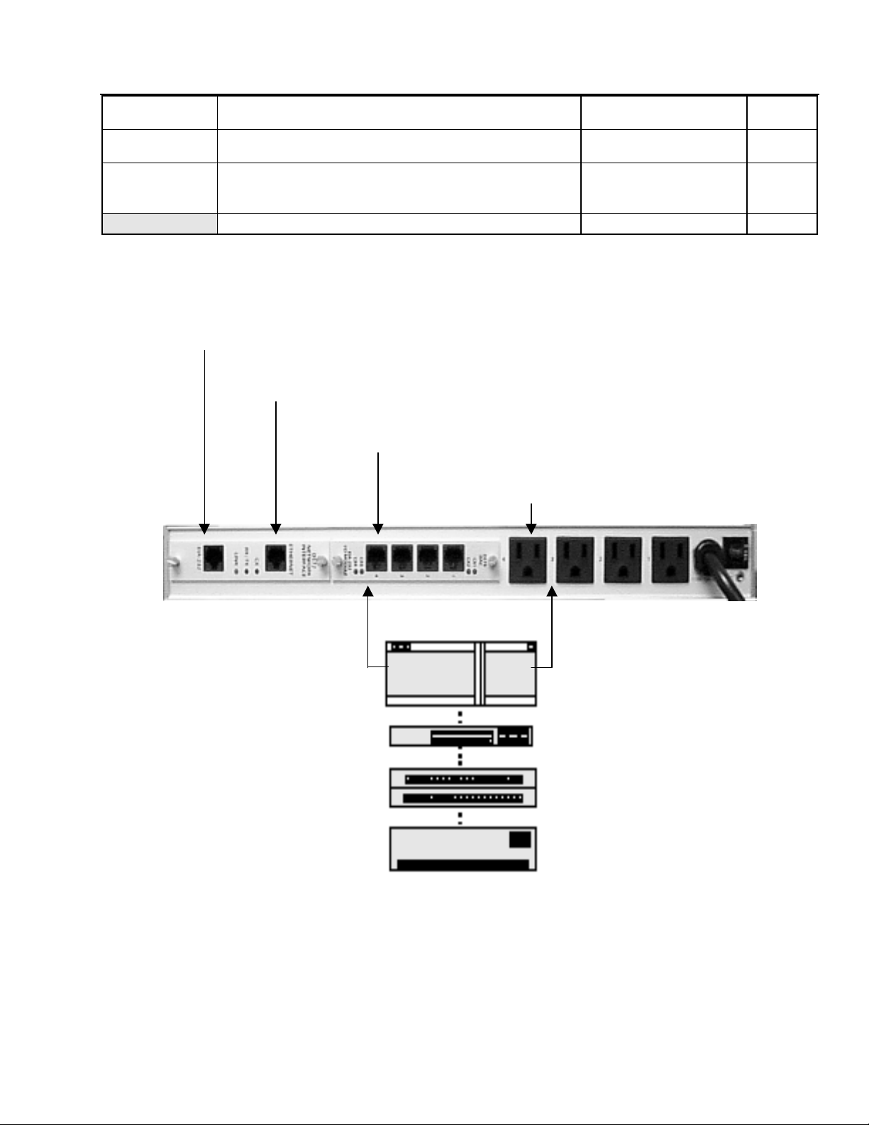
RS-232 Interface For Local Access or
Connection to external modem for dial
backup
Ethernet Interface Telnet Access
RS-232 Console Connection
Power Connection
Enter the timeframe or 0
to disconnect.
Press “E” to enable this
function
Enter the timeframe in 1
msec in crements between
1 and 9999 msecs.
20
20
20
Control
Port
Access
Power
Control
Router
DSU
Hub
Server
2
Page 8

DS72 HOST MODULE OWNER’S MANUAL
DS72 QUICK START
DS72 QUICK START
This section describes the basic steps required to set up and configure your DS72. If you need to
acquaint yourself further with the setup, configuration, and operations, see “Detailed Operations and
Configuration” beginning on page 8.
GETTING STARTED
Befo re the DS72 can be us ed within a networ k, ther e are a few para meter s w hich must be configu red.
For an initial setup, connect the serial port of your computer to the RJ-45 port labeled “EIA-232” on t he
DS72 module using the 9FRJ45PC-4 adapter and the RJ08X007 (8 pin crossed) cable.
With standard serial communications software or a terminal, set serial communications parameters to
9600 bps, 8 data bits, 1 stop bit, and no parity. This will allow direct communicat ions with the DS72
module. Appl y powe r to the DS -Series unit. The following main menu w ill appear:
Data Switch Series - F.1.00
Bay Te chnical Associates
Unit ID: BA YT EC H DS 72
Port Select Code: $BT
Attention Character: ;
Device A (2,1)...........1
Device B (2,2)...........2
Device C (2,3)...........3
Device D (2,4)...........4
DS-RPC (3,1)...........5 (if connected in a DS-RPC unit)
Configure.......................C
Status..........................S
I/O Mo dules Reset........... ....RM
Unit Rese t. .. .. ........ .. .......R U
Exit... .. .. .. ........ .. ........ .X
Logout. .. .. .. ........ .. ........ .T
Ente r Request :
NOTE
: Depending on the DS series or DS-RPC model, the menus may vary according to t he
number of DS74 modules installed in the unit.
At a minimum, the IP Address, Subnet Mask and Gat eway must be programmed in or der to access the
unit via your network. At the “Enter Request:” prompt, type “C” followed by <cr>. The following menu
is dis pla ye d:
3
Page 9

DS72 HOST MODULE OWNER’S MANUAL
Copyright(C) Bay Technical Associates 1998
DS-72 Data Switch Series - Telnet Host Module
Revisio n F. 1. 00
Module 1
Status. .. .. .. ........ .. ........ .1
Serial Port Configuration.......2
Port Device Name................3
Port Select Code................4
Atte ntion Character....... ......5
Disconn ec t Ti me guard... .. .......6
Connect Port ID Echo............7
Logi n Setup............... ......8
Network Port Configuration......9
Unit ID.. .. .. .. ........ .. .......1 0
Conf igure Another Module.... ....11
Exit............................X,CR
DS72 QUICK START
Type “9”, followed by <cr> to access the Networ k Port Co nfigurat ion. The fo llowing menu is disp layed:
Netw ork Configuration
IP Address: 0.0.0.0
Subnet Ma sk : 0. 0. 0.0
Gateway: 0.0.0.0
Ethernet Address: 00.C0.48.06.1A.81
Connection Inactivity Timeout (mins): 0
Carriage Return Translation: Disabled
Break Length (msecs): 350
IP Addres s. .. .. ........ .. ........ .1
Subnet Ma sk .. .. ........ .. ........ .2
Gateway .. .. .. ........ .. ........ .. .3
Activit y Ti me ou t....... .. ........ .4
Carriage Return Translation.......5
Brea k Length.............. ........6
Exit..............................X,CR
Ente r Request :
Se lectio ns 1 a nd 2 w ill allo w you to inpu t t he ad dre ss in a do tt ed dec imal for mat. For examp le, typin g
“1”, followed by <cr> will display:
Enter IP address in dotted decimal form :
Enter the address in the following for mat: nnn.nnn.nnn.nnn where n is any number. If you are unsure
of this address, co ntact your network administrato r. The subnet mask and gateway are programmed in a
similar fashion. When programming is complete, type “X” followed by <cr>. The system must be reset
for these setting s to be applicab le.
If this is not an initial set-up and password has been enabled, you are prompted to login. After logging
in successfully, access the main menu by sending the attention character five times (;;;;;).
4
Page 10

DS72 HOST MODULE OWNER’S MANUAL
INSTALLATION
INSTALLATION
UNPACKING
Compare the unit and serial number of the equipment you rece ived to the packing slip located on the
outside of the box. Inspect equ ipment carefully for damage that may have occurred in shipment . If t here
is damage to the equipment or if mater ials are missing, contact Ba yTech customer service at 228-4678231 or call toll free inside the United States at 800-523-2702.
NOTE:
Keep the shipping container and packing material in the event future shipment is
required.
PREPARING THE INST ALLATION SITE
The installation area shou ld be clean and free of extre me temperat ur es and humidit y.
POWER
CAUTION:
This unit is int ende d for indoo r use only. D o not inst all nea r wat er or expo se t his
unit to moisture. To prevent heat buildup, do not coil the power cord when in use. Do not use
extension cords. Do not attempt to make any internal changes to the power source. Do not
attempt to modify any portion or component of a DS72 module unless specifically directed by
BayTech p e rso nnel. BayT ech will pe rfo rm mos t inte rnal changes.
CAUTION:
Before removing or replacing any modules, turn off main power switch locat ed on
the DS-Series Base Unit. Communication to the DS-Series Data Switch will be disrupt ed while
power is off.
5
Page 11

CABLING
RJ-45 CABLES AND ADAPTERS
DS72 HOST MODULE OWNER’S MANUAL
CABLING
IMPORTANT:
The DS72 network interface module has an RJ-45 port which uses an 8-pin
crossed modular cable to connect to a local EIA-232 device such as a computer terminal or
external modem. Most serial computers do not have RJ-45 connections; t herefore an adapter is
provided with this unit to convert from a DE-9 connector to an RJ-45 co nnector ( Bay Tech Part
No. 9FRJ45PC-4). An adapter to convert from a DB-25 co nnecto r to an RJ-45 connector is also
available from Bay Tech, upon request (Bay Tech Part No. 25FRJ45PC-4). The 8-pin crossed
modular cable is configured to operate with these adapters.
CAUTION:
All power should be removed from the DS72 unit prior to removing or installing
cables.
The DS72 Et hernet co nnect ion requ ires a straig ht cable betwee n the et hernet port of the DS 72 modu le a nd
the network hu b. The “LINK” light will lig ht gr ee n when a good link has been establis hed.
DS72 EIA-232 RJ-45 Pin/Signal Definition
Pin EIA-232
Description
Signal
1 Hands hake Out (DTR) Line Driver Inactive State = High: +12V when power is applied.
Used as a handshake line to enable/d isab le t he receiving of characters.
2 Gnd Signal ground
3 Handshake Out (RTS) Line Driver Inactive St ate = High: +12 V when power is applied. Not
used to enable/disable.
4 TX Out Transmit Data (data out)
5 RX In Receive Data (dat a in)
6 Handshake In (DSR) Handshake In. –12V when not used.
7 Gnd Signal ground
8 Hands hake In (CTS) Used as a handshake line to enable/disa b le t he rece iving of
characters.
6
Page 12

CONDUCTOR
COLOR
BLUE
ORANGE
BLACK
RED
GREEN
YELLOW
BROWN
GRAY
PIN
1
2
3
4
5
6
7
8 8
Fig 4: Cro s s ed 8-pin Modu lar Cable
BayTech Part No. RJ08X007
DS72 HOST MODULE OWNER’S MANUAL
CABLING
RJ-45RJ-45
PIN
1
2
3
4
5
6
7
COLOR
BLUE
ORANGE
BLACK
RED
GREEN
YELLOW
BROWN
GRAY
Fig 5: D E-9 PC Seri al Port Adapter
BayTech Part No. 9FRJ45PC4
7
Page 13

DS72 HOST MODULE OWNER’S MANUAL
DETAILED OPERATION AND CONFIGURATION
DETAILED OPERATION AND CONFIGURATION
The following section, “Detailed Operation and Configuration,” provides a detailed approach to
accessing, operating, and configuring the DS72 network interface module.
NOTE
: It is important that you type all commands correctly. Any combination of wrong
entries results in an erro r mess ag e.
ACCESSING MAIN
MENU
NOTE
: Depending on the DS-Series model, the menus may vary accor ding to t he number o f
DS74 modules installed in the unit.
Apply power to the module. The following header and main menu appear:
Data Switch Series - F.1.00
Bay Te chnical Associates
Unit ID: BA YT EC H DS 72
Port Select Code: $BT
Attention Character: ;
Device A (2,1)...........1
Device B (2,2)...........2
Device C (2,3)...........3
Device D (2,4)...........4
DS-RPC (3,1)...........5
Configure.......................C
Status..........................S
I/O Mo dules Reset........... ....RM
Unit Rese t. .. .. ........ .. .......R U
Exit... .. .. .. ........ .. ........ .X
Logout. .. .. .. ........ .. ........ .T
Ente r Request :
NOTE:
Password feature is case sensitive.
SELECTING A DEVICE
Menu Driven
Selection
From the main menu, se lect the number that co rr esponds to the device you
wish to access, followed by <cr>. To return to the main menu, send the
ASCII Character
String
If this is not an initia l set -u p and P asswo rd has alr ead y bee n ena bled, you
are prompt ed to log in. A fter logg ing in suc cess ful ly, t he main menu wi ll
appear.
There are two methods o f selecting a device, menu dr iven se lection and
ASCII character string method.
attention character five times (;;;;;).
Another method of selecting devices and operatingthe DS-Series and DS
RPC is the ASCII character string metho d. To select a device located on
a peripheral Port, type $BTm,p where m is the module and p is the port.
To configure a module, type $BT and the module number followed by
8
Page 14

DS72 HOST MODULE OWNER’S MANUAL
DETAILED OPERATION AND CONFIGURATION
<cr>, then $CONFIG followed by <cr>. This will allow access to the
configuration menu for that module. Once configuration is complete, type
X for “Exit” followed by <cr>. To access the main menu, type the
attention charact er five times.
NOTE:
NOTE:
You must exit main menu to send ASCII char acter string commands.
While operating using the ASCII Character String method, consider placing the DS-
Series in binary mode.
Binary Mode
Te rm ina te Bin ary
Mode
If binary data containing the port select code is sent to a module, the DSSeries may interpret the data as a command to change port s. Binary mode
prevents such an occurrence by placing the DS-Series in a mode which
does not look at the data. This provides a reliable binary data transmission.
However, before a connection can be made to another port, the binary
mo de must be termi na ted.
Place the port in binary mode by sending the port select code, a capital B,
and a carriage return
($BTB).
For example, if using the default Port
Select Code ($BT), place Module 2, Port 1 in binary mode by typing
$BT2,1<cr>$BTB<cr>.
From the terminal emulation software, send a BR EAK condition
command to terminate binary mode. You may have to consult the
software users’ manual for the specific BREAK condition command for
the emulation software you are using. For example, the BREAK condition
command for PROCOMM PLUS is “Alt B.”
NOTE:
The break length for emulation software is progra mmed within that so ftware. The break
length for a TELNET session is programmed within the BayTech firmware. This procedure is
discussed on page 20.
Data Switch Series - F.1.00
Bay Te chnical Associates
Unit ID: BA YT EC H DS 72
Port Select Code: $BT
Attention Character: ;
Device A (2,1)...........1
Device B (2,2)...........2
Device C (2,3)...........3
Device D (2,4)...........4
DS-RPC (3,1)...........5
Configure.......................C
Status..........................S
I/O Mo dules Reset........... ....RM
Unit Rese t. .. .. ........ .. .......R U
Exit... .. .. .. ........ .. ........ .X
Logout. .. .. .. ........ .. ........ .T
Ente r Request :
9
Page 15

DS72 HOST MODULE OWNER’S MANUAL
DETAILED OPERATION AND CONFIGURATION
DS72 CONFIGURATION
If you are using the Menu Selection Method, select C, “Configure,”
followed by <cr> from the DS72 Main Menu. The following selection
menu appears:
Configuration
Module 1. .. .. .. ........ .. .......1
Module 2. .. .. .. ........ .. .......2
Module 3. .. .. .. ........ .. .......3
Select Po rt .. .. ........ .. .......S
Exit... .. .. .. ........ .. ........ .X ,C R
Ente r request:
If you are using the ASCII Character String Method, exit the main menu,
then select the module to configure. To select Mo dule #1, type $BT1<cr >.
The DS72 responds “Requested Connection Made.” Send the ASCII
configuration command $CONFIG. The configuration menu appears.
Enter the number of the module to configure, followed by <cr>. To
configure the host module 1, select #1. The following conf iguration menu
appears for the DS72:
Copyright(C) Bay Technical Associates 1998
DS-72 Data Switch Series - Telnet Host Module
Revisio n F. 1. 00
Module 1
STATUS
Status. .. .. .. ........ .. ........ .1
Serial Port Configuration.......2
Port Device Name................3
Port Select Code................4
Atte ntion Character....... ......5
Disconn ec t Ti me guard... .. .......6
Connect Port ID Echo............7
Logi n Setup............... ......8
Network Port Configuration......9
Unit ID.. .. .. .. ........ .. .......1 0
Conf igure Another Module.... ....11
Exit............................X,CR
Ente r Request:
View the status of most user programmable features by selecting #1,
“Status,” from the configuration menu, followed by <cr>. The following
menu appears:
Installed Modules :
Port Select Code is.............$BT
Attention Character is .........;
Disconnect Time Guard is........Enabled
Port ID Echo is.................Device Name
Unit ID is......................BAYTECH DS72
Network Setup :
Etherne t Ad dr es s............. .. .00.C0.48.06.1A . 81
IP Addres s. .. .. .............. .. .200.4.2.65
Subnet Ma sk .. .. .............. .. .255.255.255.0
Gateway .. .. .. .............. .. ...200.4.2.1
Inactiv it y Ti me out (mins)...... .1
Break Length (msecs)............350
10
Page 16

DS72 HOST MODULE OWNER’S MANUAL
DETAILED OPERATION AND CONFIGURATION
Login Setup :
Header is .. .. .. .............. .. .Enabled
Passwor d is .. .. .............. .. .Disabled
Menu is.. .. .. .. .............. .. .Enabled
Auto Connect Port is............Module 3,Port 1
Auto Conn ec t is .. .............. .D isabled
SERIAL PORT
CONFIGURATION
DS72 modules perform data rate conversions for devices using
different serial configurations.See Appendix A, “SPECIFICATIONS” for
available serial parameters.
Default Serial Port Configurations are
9600 bps, 8 data bits, 1 stop bit, no parity, Xon/Xoff disabled, RTS
high, and DTR low.
From the configuration menu, select #2, “Serial Port
Configuration”, followed by <cr>. The DS72 unit displays the following
table:
Module 1 Serial Port Configuration :
Port Device
Name
1 EIA-232 9600 8 1 None Off Off High High
Save.......1 Parity............5
Baud Rate..2 Xon/Xoff..........6
Word Size..3 RTS Line Driver...7
Stop bits..4 DTR Line Driver...8
Enter Request :
Baud
Rate
Word
Size
Stop
Bits
Parity Xon/
Xmit
Xoff/
Recv
Line
DTR
Drive
RTS
Select the corresponding number to configure baud rate, word size, stop
bits, parity...
NOTE:
DTR is unchangeable when configuring the serial port.
For examp le, t o change the baud r at e t o 115.2 K, select #2, “Set B aud Rat e, ”
followed by <cr>.
The DS71 displays the following list of available baud rates:
1 for 300
2 for 600
3 for 1200
4 for 2400
5 for 4800
6 for 9600
7 for 19200
8 for 38400
9 for 57.6K
A for 76.8K
B for 115.2K
Enter Request :
Type "B" for 115.2K baud rate. The DS72 responds with the new
configurat io n st atus:
11
Page 17

DS72 HOST MODULE OWNER’S MANUAL
DETAILED OPERATION AND CONFIGURATION
Module 1 Serial Port Configuration :
Port Device
Name
1 EIA-232 115.2K 8 1 None Off Off High High
Save.......1 Parity............5
Baud Rate..2 Xon/Xoff..........6
Word Size..3 RTS Line Driver...7
Stop bits..4 DTR Line Driver...8
Enter Request :
Baud
Rate
Word
Size
Stop
Bits
Parity Xon/
Xmit
Xoff/
Recv
Line
DTR
Drive
RTS
Set Word S ize by select ing #3, “Set Word S ize.” The DS 72 displays the
following list of available word sizes:
1 For 5
2 For 6
3 For 7
4 For 8
Enter the corresponding number for the desired word size. The DS72
responds with the new configuration status:
Module 1 Serial Port Configuration :
Port Device
Name
1 EIA-232 9600 7 1 None Off Off High High
Baud
Rate
Word
Size
Stop
Bits
Parity Xon/
Xmit
Xoff/
Recv
Line
DTR
Drive
RTS
Save.......1 Parity............5
Baud Rate..2 Xon/Xoff..........6
Word Size..3 RTS Line Driver...7
Stop bits..4 DTR Line Driver...8
Enter Request :
To permane ntly save configur ation changes, select 1, “S ave,” from the
selection menu, followed by <cr >. The DS72 responds:
Change Host Device to Match NEW Configuration
Before Answering this Request
Save Changes Permanently ? (Y/N) :
IMPORTANT:
This message reminds you to change the serial port configuration of the host
termina l to match the new co nfigurat ion cha nges made to the ser ial port on the host module be fore
answering the question. If they do not match, the DS72 will be unable to interpret the next
command, and you will be unab le to acce ss an y co nnecte d u nit. I f t his happ ens, r ec ycle pow er a nd
reconfigure the unit. Make any necessary changes to the host device before answering "Save
Changes Permanently? "
If you have made necessary changes to the host device, type "Y" for yes,
followed by <cr>. New configuration changes are stored permanently in
no n-volati le memory.
PORT DEVICE NAME
Port Device Name is a user programmable feature that uniquely identifies
the port (or device connected to the port) you are configuring.
The default
name is EIA-232.
12
Page 18

DS72 HOST MODULE OWNER’S MANUAL
DETAILED OPERATION AND CONFIGURATION
Select #3, “Port Device Name,” followed by <cr>. The DS72 module
responds:
Module 1 Serial Port Configuration :
Port Device
Name
1 EIA-232 9600 8 1 None Off Off High High
Baud
Rate
Word
Size
Enter Port Device Name (Max. 16 characters):
or press ENTER for no change ...........:
Stop
Bits
Parity Xon/
Xmit
Xoff/
Recv
Line
DTR
Drive
RTS
Enter a new port device name up to 16 charact ers. For example, if you are
using mult iple DS units o n a network, and you w ant t o name the ho st dev ice
Southeast Region, type "SE REGION" followed by <cr>. The module
responds:
Module 1 Serial Port Configuration :
Port Device
Name
1 SE REGI ON 9600 8 1 None Off Off High High
Baud
Rate
Word
Size
Enter Port Device Name (Max. 16 characters):
or ENTER for n o change ...........:
Stop
Bits
Parity Xon/
Xmit
Xoff/
Recv
Line
DTR
Drive
RTS
PORT SELECT
CODE
to the DS72 module to sel ect an I/O port on a DS 74 periph eral mod ul e. The
The P ort Sele c t C ode is an ASCII charac ter strin g sent by the host terminal
Port Select Code can ra nge from 1 to 8 charact ers and is user programmable
Default Port Select Code is $BT.
From the configuration menu, select #4, “Port Select Code,” followed by
<cr>. The host module disp la ys the cur rent port select code and ask s if yo u
wan t to change:
Port Select Code is................$BT
Change It ? (Y/N) :
Type "Y" to change the port select code, followed by <cr>. The host module
responds:
Enter Port Select Code (Max. 8 characters):
Enter a new port select code fo llo wed b y <cr>. For examp le, if you wa nt to
identi fy t he port select code as “BAYTEC H,” type BAYTE CH followe d by
<cr>. The DS72 module displays t he new port select code and asks if you
wan t to change.
Port Select Code is................BAYTECH
Change It? (Y/N):
.
13
If there are no addit ional changes, type "N" for no, followed by <cr>. The
DS72 module stores the new port select code permanently in non-volatile
memory and returns to the configuration menu.
Page 19

DS72 HOST MODULE OWNER’S MANUAL
DETAILED OPERATION AND CONFIGURATION
ATTENTION
CHARACTER
The Attention Character i s a char acte r used in sequence to invoke the main
menu.
Default Attention Character is a semicolon (;).
From the conf igurat io n menu, s e le ct #5, “Attention Charact er,” follow ed by
<cr>. The host module displays the current attention character and asks if
you want to change.
Attention Character is............ ;
Change It? (Y/N):
For example, if you want to change the attention character type “Y”
followe d by <cr >. T h e DS72 module respo nds :
Enter Attention Character:
Enter a new attention character. For "%", type % followed by <cr>. The
DS72 displays the new attention character and asks if you want to change.
Attention Character is............ %
Change It? (Y/N):
If there are no additio nal changes, type “N” for no fol lowe d by <cr>. T he
DS72 module stores the new attent ion character in non-volatile memory and
returns to the main configuration menu.
DISCONNECT TIME
When usi n g the A ttention Character Method, it is possible for the same
GUARD
DS72 as the attention character. This could result in unwanted port
disconnection. If enabled, the Disconnect Time Guard feature provides
reliable binary data transmission by providing a one-second “t imeguar d”
after the DS72 receives the attention character. If more data is received
within the delay period, the DS72 treats the character as data, not an
attention character; thereby preventing unwanted port disconnection.
Default Disconnect Time Guard is disabled.
From the conf igurat io n menu, select #6, “Disco nnect T ime Gu ar d,” follo wed
by <cr>. T he DS 72 module disp lays t he c urre nt stat us and ask s if you wa nt
to change:
Disconnect Time Guard is..................Disabled
Enable? (Y/N, CR for no change):
Type “Y” or “N” fo l low ed b y <cr> t o to gg le the e xist ing st at us or t ype <cr >
for no change. The DS72 module stores the Disconnect Time Guard
se lection in non-volatile me mory and returns t o the con figuration menu.
CONNECT PORT
ID ECHO
port number you are connect ed to. Choose the por t device name or the
When enabled , C onn ect Port ID Echo identifies the module number and
module and port number to echo when a DS72 module select s a po rt on a
DS74 module.
character being sent as data from another device to be interpreted by the
Default Connect Port ID Echo is disabled.
From the co nfigur ation menu, select #7, “Co nnect Po rt ID Echo,” followed
14
Page 20

DS72 HOST MODULE OWNER’S MANUAL
DETAILED OPERATION AND CONFIGURATION
by <cr>. The DS72 module present s the current status of Port ID Echo and
asks if you want to change:
Port ID Echo is....................Disabled
Change It? (Y/N):
Type “Y” follo wed by <cr> to to ggle Connect Po rt ID Echo o r “N” for no
fo l lo we d by <cr>. If you answer yes , the DS72 module responds:
Port ID Echo is...................Device Name
Disable Port ID Echo..............1
Use Module, Port Number...........2
Use Device Name...................3
Exit..............................X,CR
Ente r Request :
If you are e nabling Port ID E cho, choose #2 t o echo t he modu le and po rt
number, followed by <cr>. Choose #3 to echo the device name, followed by
<cr>. The DS72 module stores t he selected Connect Port ID Echo in nonvolatile memory and returns to the configuration menu.
NOTE:
DS74 is used.
LOGIN SETUP
Header
If you choose #3, “Use Device Name,” the programmed Port Device Name for the selected
This configures how the DS72 responds upon login. You can
Enable/Disable the Header and Menu and/or Enable/Disable/Program
Password and Auto Connect Port.
From the configurat ion menu, select #8, “Login Setup, ” fo llowed b y <cr>.
The follow ing menu app ears:
Header..........................1
Password........................2
Menu............................3
Auto Conn ec t. .. .............. .. .4
Exit... .. .. .. .............. .. ...X,CR
Ente r Request :
If e nab le d, the follow in g h e ad e r a ppea r s wit h the mai n me n u u p on in itiation
of power or after a modem connection to the host module has been
established. If disabled, the header does not appear with the main menu.
Default Header is enabled.
Data Switch Series – F.1.00
Bay Technical Associates
Unit ID: BAYTECH DS72
Port Select Code: $BT
Attention Character: ;
15
From the selection menu, sel ect #1 , “ Head er , ” followed by <cr>. The DS72
displays the current header status and asks if you want to enable:
Page 21

DS72 HOST MODULE OWNER’S MANUAL
DETAILED OPERATION AND CONFIGURATION
Header is......................... Disabled
Enable? (Y/N, CR for no change):
Type “Y” follo wed b y <cr > if yo u want t o ena ble Head er st at u s. T ype “N ”
followed by <cr> if you want to disable Head er . E nt er <cr > for no change.
Passwor d
To change Password or Enable/Disable Password upon login, select #2,
“Passwo rd, ” from the select io n menu, fo llow ed b y <cr>.
is BTA, dis a ble d .
Change Password....................1
Enable/Disable.....................2
Exit...............................X, CR
The DS72 module responds:
Default Password
To change the current pas sword, se lect #1, “Change Pas sword,” followed by
<cr> . The DS72 m odule responds:
Enter New Password (1 - 8 char., CR to end):
Enter the new password u p to 8 ASCII character s followe d by <cr>. T he
DS72 module stores the new password in non-volatile memory and returns
to the selection menu.
To toggle Password status, select #2, “Enable/Disable,” followed by <cr>.
The DS72 module displays the current status and asks if you want to enable:
Password is ......................... Disabled
Enable? (Y/N, CR for no change):
Enter “Y” followed by <cr> if you want to enable Password. Type “N”
followed by <cr> if you want to disable Password. Enter <cr> for no
change.
Menu
NOTE:
To invoke the main menu when disabled, enter the attention character five times (;;;;;).
Ena b le / D is a b le M e nu u po n lo gin
. Default menu is enab led.
following header appears upon login without the main menu :
Data Switch Series - F.1.00
Bay Te chnical Associates
Unit ID: BA YT EC H DS 72
Port Select Code: $BT
Attention Character: ;
If disabled,the
16
Page 22

DS72 HOST MODULE OWNER’S MANUAL
DETAILED OPERATION AND CONFIGURATION
If enabled, the following header and menu appears:
Bay Te chnical Associates
Unit ID: BA YT EC H DS 72
Port Select Code: $BT
Attention Character: ;
Device A (2,1)...........1
Device B (2,2)...........2
Device C (2,3)...........3
Device D (2,4)...........4
DS-RPC (3,1)...........5
Configure.......................C
Status..........................S
I/O Mo dules Reset........... ....RM
Unit Rese t. .. .. .............. .. .RU
Exit... .. .. .. .............. .. ...X
Logout. .. .. .. .............. .. ...T
To toggle the menu status, select #3, “Menu,” from the selection menu,
followe d by <cr >. T he DS72 module disp lays t he curr ent st atu s and ask s if
you want to change:
Menu is............................ Disabled
Enable? (Y/N, CR for no change):
Auto Connect Port
NOTE
: The aut o connect por t has priority over the login setup menu. If Auto Connect Po rt is
enabled, the main menu is automatic all y disab led.
Type “Y” followed by <cr> if you want to enable Menu. Type “N”
followed by <cr> if you want to disable Menu. T yp e <cr> for no change.
If Auto Connect Port has been enabled, establishing a communication
link to the DS72 module will connect the user to the designated I/O port.
This also happens when a connection is esta blis hed via the serial port .
Select # 4, “Auto Conne ct Port ”, from the selection menu, followed by <cr>.
The following Auto Connect Port menu appears:
Auto Connect Port is..............Module 3,Port 1
Auto Conn ec t is .. .............. .. .Disabled
Change Auto Connect Port..........1
Enable/Disable....................2
Exit..............................X,CR
Ente r Request :
The DS72 module displays the current auto connect port and its current
status. To change the a uto connect po rt module number and po rt number,
select #1, “Change Auto Connect Port,” followed by <cr>. The DS72
module responds:
17
Auto Connect Port is..............Module 3,Port 1
Enter Auto Connect Module (2 to 9) :3
Enter Auto Connect Port (1 to 4) :1
Auto Connect Port is..............Module 3,Port 1
Page 23

DS72 HOST MODULE OWNER’S MANUAL
DETAILED OPERATION AND CONFIGURATION
Enter the module t o connect automatically, followed by <cr>. E nter the port
to connect aut omatically, fo llo wed by <cr>. The DS72 module sto res the
new settings in non-volatile memory and returns to the Auto Connect Port
menu.
Toggle Auto Connect Port feature by selecting #2, “Enable/Disable,” fro m
the Auto Connect Port menu followed by <cr>. The DS72 module displays
the curr e nt aut o co nnect po rt st at us and a sks if you wa nt t o ena ble.
Default
Auto Connect Port is disabled.
Auto Conn ec t is .. .............. .. .Disabled
Type “Y” fol lowed b y <cr> if you wa nt t o ena b le Auto Co nnect Po rt . T ype
“N” follow ed by <cr> if you wa nt to disable Auto Co nnect Port . Type <cr >
for no change. The DS72 module stores Auto Connect Port configuration in
non-vol atil e memory and retu rns to the A uto Connect Port men u.
NETWORK PORT
CONFIGURATION
IMPORTANT:
For network access, you must configure the IP addresses, Subnet Mask, and
Gateway Address. The module must be reset for networ k changes to t ake effect .
This sets up the network parameters for the DS72.
From the configuration menu, select #9, “Network Port Configuration”,
followed by <cr>. The following menu appe ars:
Netw ork Configuration
IP Address: 200.4.2.65
Subnet Ma sk : 25 5. 255.255.0
Gateway: 200.4.2.1
Ethernet Address: 00.C0.48.06.1A.81
Connection Inactivity Timeout (mins): 1
Carriage Return Translation: Disabled
Break Length (msecs): 350
IP Addres s. .. .. .............. .. ...1
Subnet Ma sk .. .. .............. .. ...2
Gateway .. .. .. .............. .. .....3
Activit y Ti me ou t............. .. ...4
Carriage Return Translation.......5
Brea k Length.............. ........6
Exit..............................X,CR
Ente r Request :
IP Address
The IP address is the networ k address assigned by your network manager
for your network.The IP Address consist of four bytes, each byte ranging
from 0 to 255. This parameter must be programmed before the DS72
may be accessed via the networ k.
From the configuration menu, select #1, “IP Address,” fo llowed by <cr>.
The DS72 responds:
Enter Module IP address in dotted decimal form:
18
Page 24

DS72 HOST MODULE OWNER’S MANUAL
DETAILED OPERATION AND CONFIGURATION
Enter the Module IP Address (Example: 200.4.3.50), followed by <cr>.
The DS72 resumes the configuration menu.
Default Mo dule IP Address
is 0.0.0.0.
If you fail to enter the Module IP Address in dotted decimal form, the
DS72 responds again:
Enter Module IP address in dotted decimal form:
The DS72 responds indefinitely with t he same request until the Module IP
Address in entered in the correct form.
NOTE:
should be reset upon completion of configuration.
Subnet Mask
There should be no active connections while configuring the DS72 module. The unit
The Subnet Mask is a bit mask that identifies the network portion of the IP
address, allowing the DS72 to determine whether to send a packet directly
to the client or to a gateway. The Subnet Mask consist o f four bytes, each
byte ranging from 0 to 255.
before the DS-Series can be accessed through the network
This parameter must be programmed
.
From the configuration menu, select #2, “Subnet Mask,” followed by
<cr>. The DS72 responds:
Enter Subnet Mask in dotted decimal fo rm:
Enter the Subnet Mask (Example: 255.255.255.0), followed by <cr>. The
DS72 resumes the configuration menu.
Default Subnet Mask is 0.0.0.0.
If you fail to enter the Subnet Mask in dotted decimal form, the DS72
responds again:
Enter Subnet Mask in dotted decimal fo rm:
The DS72 responds indefinitely with t he same request until the Subnet
Mask is entered in the correct for m.
Gateway
19
The Gat eway is the address of a ro uter for connection to their networks.
The Gateway address consists of four bytes, eac h byte ra nging from 0 to
255. If your network uses gateways, this parameter must be programmed
before the DS72 can be accessed thro ugh a network.
From the configuration menu, select #3, “Gateway,” followed by <cr>.
The DS72 responds:
Enter Gateway address in dotted dec imal form:
Enter the Gateway address (Example: 200.4.5.50), followed by <cr>. T he
DS72 resumes the configuration menu.
0.0.0.0.
If you fail to enter the Gateway address in dotted decimal for m,
Default Gateway address is
the DS72 responds again:
Page 25

DS72 HOST MODULE OWNER’S MANUAL
DETAILED OPERATION AND CONFIGURATION
Activity Ti meout
Carriage Return
Translation
When this option is enabled, the DS72 will automatically disconnect, if there
Press “E” to enable the DS 72 Telnet processor to stri p line feeds or nulls
which follow carriage returns. Press “D” to allow the characters to pass
Enter Gateway address in dotted dec imal form:
The DS72 responds indefinitely with t he same request until the Gateway
address is entered in the co rrect for m.
is no a c tivity, after the program med amou nt o f time .
(disabled)
. The enabling input can be from 1 to 120 minutes.
Default is 0
From the configuration menu, select #4, “Activity Timeout ,” followed by
<cr>. The DS72 responds:
Connection Inactivity Timeout is 0 minutes
Enter timeout, in minutes (<=120, 0 to disable) :
Enter 0 to disable or a number between 1 and 120 (inclusive) to set the
timeo ut.
through and press <cr> to leave this option unchanged.
“disabled”
.
Default is
Programmable Break
UNIT ID
From the configuration menu, select #5, “Carriage Return Translation,”
followed by <cr>. The DS72 responds:
Carriage Return Translation is....Disabled
Enable ? (Y/N), CR for no change) :
Us ers may co nfigur e the DS72 for a br eak lengt h o f 1 - 1000 milliseco nds .
When a user, running a Telnet session with the DS72 and connected to a
ser ial port o n a DS74, se nds a Te lnet br eak co mmand ( 0xF3) t o the D S72,
the ser ia l port will send a bre a k signa l of t he pro gr ammed d ur at io n.
is 350 milliseconds
.
Default
From the configuration menu, select #6, “Break Length,” followed by
<cr>. The DS72 responds:
Break Length is (msec)............350
Enter break length, in milliseconds (<10000, 0 to disable) :
The unit ID (64 chars. max.) appears in the DS72 configuration menu and
uniquely identifies the module.
Default Unit ID is BAYTECH DS72.
Select 10, “Unit ID,” from the configuration menu, followed by <cr>. The
DS72 mod ule displ ay s the cu rren t Un it ID and asks for a new name:
Unit ID is ................ ........... ...... BAYTECH DS72
Change It? (Y/N Change) :
Enter Unit ID (64 chars. max.) :
20
Page 26

DS72 HOST MODULE OWNER’S MANUAL
DETAILED OPERATION AND CONFIGURATION
Enter the desired Unit ID, followed by <cr.> The DS72 module stores t he
changes in non- vo la t ile me mory and re t u r ns to the co n fig ur a t io n me nu .
STATUS
SYSTEM
NETWORK
From the main menu, type “S” to select “Status,” followed by <cr>. T he
follow ing me nu appe a rs:
DS-72 Status Menu.
Enter selection, CR to exit.
1)...S ystem
2)...Network Interface
3)...L ogged Users
Ente r Request :
Select “1” to display the System Status:
System St at us :
Available local memory (256 byte buffers): 21
TCP sockets in use: 1
System up time (hh:mm:ss): 00:04:27
Select “2” to display the Network Status:
Network Status:
Medium st at us : go od
Medium fa ul ts : 0
Xmit bufr errs: 0
Available send buffers: 11
Rece ive queue status: open
LOGGED USERS
I/O MODULES RESET
UNIT RESET
NOTE:
Resetting the unit does not return user selections to their default settings.
Menu
Driven
Selection
Select “3” to display the Logged Users:
Active Us er s:
User Address Internal Conn Status
1 * 200.4.2.52 +
From the main menu, type “RM” to se lect “I/O Modules Reset, ” followed
by <cr>. The DS72 module recycles power to all I/O ports on all
peripheral modules and responds:
I/O Modules Reset Succe ss fully. Strike CR to Continue
Use the menu driven selection or the ASCII charact er st r ing met ho d to
reset the DS-Series Unit:
From the main menu, type “RU” to select “Reset Unit,” followed by
<cr>. The DS72 module resets the unit and respo nds:
21
Reset Unit……
Page 27

DS72 HOST MODULE OWNER’S MANUAL
DETAILED OPERATION AND CONFIGURATION
Allow approximately 10 seconds for the unit to reset.
ASCII
Character
send the following command:
To reset the DS-Series Unit using the ASCII charact er string method,
String
$BTRESET<cr>
DIAGNOSTICS
To detect hardware, cabling, or configuration problems upon initializat ion
of power, the DS72 executes a diagnostic sequence. To help determine
the cause of the problem, the DS72 has a CX LED located on the front
panel of the unit. Upon initialization of power, refer to the following table
for int erpretation.
INDICATION INTERPRETATION
Not lit Normal unconnected operat ion
Brief flash followed by a solid illumination Established connection on network port or serial port
Flashes 1 time per cycle Hardware or NIC problem
Flashes 2 times per cycle Configuration error
Flashes 3 times per cycle Cable or hub connection fault
Flashes 4 times per cycle Duplicate IP address
Remains lit w ithou t a brief fl ash p rio r to
illumination
NOTE:
Diagnostic indications override a connection indication.
Memory error
22
Page 28

REPACKAGING, SHIPPING AND RETURNING TO THE FACTORY
DS72 HOST MODULE OWNER’S MANUAL
TECHNICAL SUPPORT
BayTech has a staff of applicat ions engineers o n duty to ass ist you from 7 a.m. to 6 p.m. (CST or CDT),
Monday through Friday. If you have problems installing, setting up, or operating your Bay Tech
product, please contact BayT ech’s technical support office. For informat io n on all of BayTech’s data
communication products, cont act our Web Site at the address shown below.
Bay Technical Associates, Inc.
200 N. Second Street, P. O. Box 387
Bay St. Louis, MS 39520-1000, USA
Telephone: 800-523-2702
228-467-8231
FAX: 228-467-4551
Web Site:
www.baytechdcd.com
23
Page 29

REPACKAGING, SHIPPING AND RETURNING TO THE FACTORY
DS72 HOST MODULE OWNER’S MANUAL
REPACKAGING, SHIPPING AND RE TURNING TO THE FACTORY
If your Bay Tech unit needs service, upgrade, or repair, return it to BayTech. Before dismantling your
equipment or before returning the unit for any reason, always call Ba yTec h. T he user should never
attempt repairs on this unit. If you need to return the Bay Tech unit to the factory for repair, warr anty
work, or upgrade, follow the instr uctions below for repackaging and shipping.
INSTRUCTIONS FOR REPACKAGING AND SHIPPING:
a. Call BayTech to get a
IMPORTANT:
Return Authorization Number
.
Without this number, BayTech will not accept returns.
b. Use the original packaging if available or choose a heavy cardboar d bo x.
c. Surround your unit with a minimum o f two inches of insu la tion.
d. Be sure to seal the box securely with strapping or packing t ape. We do not recommend masking tape
or cellophane tape.
e. On the out side o f the box, p lease wr ite the Ret urn Authorization
Number.
f. Ship the unit to the following address:
Bay Technical Associates, Inc.
200 N. Second Street
Bay St. Louis, MS 39520-1000, USA
24
Page 30

FCC RADIO FREQUENCY INTERFACE STATEMENT
DS-SERIES OWNER’S MANUAL
FCC RADIO FREQUENCY INTERFACE STATEMENT
This equipment generates, uses and can radiate radio frequency energy and, if not installed and used in
accordance with this manual, may cause interference to r adio co mmunicat ion.
This equipment has been type tested and found to comply within the limits for a Class A digital device
pursuant to Subpart J of Part 15 of FCC rules. FCC rules provide reasonable protection against
interference with radio co mmunications in a commercial environment. Not installing in accordance with
th is ma nual or o perat ing this u nit in a r esident ial env ironme nt is lik ely to cause int erfere nce. I n such
cases, the user w ill be respons ible for the expense of correcting the interference.
a. Federal Communications Commission (FCC) has established rules permitting a direct
connection to the t elephone network. These connect ions use st andardized jacks. Do not use t his
equipment on party lines or coin lines.
b. If this device is malfunctioning, it may also be causing harm to the telephone network;
disconnect this device until the source of the problem is determined and repairs made. The
Telephone Co mpany may te mpor ar ily disco nne ct service until the problem is corr ect ed.
c. The Telephone Company may make changes in its technical operations and procedures. If
such changes affect the compatibility or use of this device, the Telephone Company is required
to give adequate notice of the changes. In t his case, you have the right to file a complaint w ith
the FCC.
d. If the Telepho ne Company request s infor mat ion on connected equipment to their lines, infor m
them of the following:
1. The telephone number of this unit.
2. The ringer equivalence number (indicated on the label).
3. The USOC jack required: RJ-11
4. The FCC Registration Number (indicated on the label).
The ringer equivalence number (REN) is used to determine how many devices can be connected
to you telephone line. In most areas, the su m of the RENs of all devices on a single line s hould
not exceed five. If there are too many devices attached, they may not r ing properly.
In case of equipment malfunction, BayTech should per form all repairs. It is the responsibility of
the user requiring service to report the need for service to BayTech:
25
Bay Technical Associates, Inc.
P.O. Box 387, 200 N. Second Street
Bay Saint Louis, MS 39520-1000, USA
Telephone: 228-467-8231
800-523-2702
Fax: 228-467-4551
Page 31

SPECIFICATIONS
DS72 Network Interface Module
EIA-232 Serial Port 8 pin modular connector (RJ-45)
DS72 HOST MODULE OWNER’S MANUAL
APPENDIX A
Environment
0° to 70°C
5% to 95% humidity
Indicators 1 green LINK integrity LED
1 red RX/TX Network Activity LED
1 red CX LED
Interface EIA-232, Ethernet, 10Base-T
Transmission Asynchronous
Protocols TCP/IP
Frame Types Ethernet II and SNAP (802.3)
Handshaking CTS/DTR; selectable Xon/Xoff
Baud Rate 300, 600, 1200, 2400, 4800, 9600, 19.2K, 38.4K, 57.6K, 76.8K, or 115.2K
Word Size 5, 6, 7, or 8 bit s
Stop Bits 1, 1 1/2, or 2 bit s
Parity Even, Odd, or None
Buffer Size 63 KB
Warranty One year on parts a nd labor
26
Page 32

APPENDIX B
OPERATING WITH A MODEM
U.S. ROBOTIC MO DEMS
COMMAND INTERPRETATION
DS-SERIES OWNER’S MANUAL
APPENDIX B
AT&B1
AT&C1
AT&D2
ATS0=1
ATE0
ATQ1
AT&W0
NOTE:
ROCKWELL CHIP SET MODEMS
To send all of the above at the same time, type the following command: AT&B1&C1&D2S0=1E0Q1&W0
Fixed Serial Port Rate (default)
Normal CD Operations (default)
Normal DTR Operations (default)
Auto answer telephone li ne i n 4 or fewer rings
Modem does not display keyboar d commands.
Place mode m into quiet mode
Save the modem’s configuration in non-volatile memory
COMMAND INTERPRETATION
ATS23=59
Fixed Serial Port Rate (default)
AT&C1
AT&D2
ATS0=1
ATE0
ATQ1
AT&W0
NOTE:
27
To send all of the above at the same time, type the following command: ATS23=59&C1&D2S0=1E0Q1&W0
Normal CD Operations (default)
Normal DTR Operations (default)
Auto answer telephone li ne i n 4 or fewer rings
Modem does not display keyboar d commands
Place mode m into quiet mode
Save modem’s configuration in non-volatile memory
Page 33

DS-SERIES OWNER’S MANUAL
APPENDIX B
Connecting an external modem to the serial port requires a 25MRJ45MD-6 modem adapter, an
RJ08X007 crossed 8 pin modular cable, and the jumper setting on the module as shown below. For
serial port connect ion to the co mputer, the jumper should be in the opposite position.
28
Page 34

INDEX
DS-SERIES OWNER’S MANUAL
iNDEX
A
Accessing Main Menu 8
ASCII 9, 10
Attention Character 8, 14, 15, 16
Auto Connec t P ort 17, 18
B
Baud Rate 11
Binary Mode 9
break co n dition
C
Cable 7
Cabling 6
Configuration 8, 9, 10, 11, 12, 13, 16
Co nne ct Port ID Echo 14, 15
Copyright ii
Current Passwor d 4, 8
D
Data Acquisition and Control 1
Default 4, 8, 19, 27
Devices 6
diagnostic 22
Disconnect TimeGuard 14
E
EIA-232 Port 26
EIA-232 Serial Connection 3
Exit 19
F
Fact ory Default 13, 19
FCC Statement 25
G
Gateway 18, 19, 20
H
Header 15, 16
Host communications 1
I
Installation 5
Interface 25
IP Address 18, 19, 22
M
Menu 3, 8, 10, 15, 16, 17, 21
Menu Selection Meth od 10
Modem Command Summary 27
N
Network Configuration 18, 19
O
9
Operation 8, 10, 11, 12, 13, 16
P
Parity 3, 11
Password 4, 8, 15, 16
Port Device Name 12, 13, 15
Port Select Code 8, 9, 13, 15, 16
Power 5, 22
PPP Dial-Up Connection 10
Q
Quick Start 3
R
Repackaging 24
Reset 21
Returning 24
RTS/DTR Line Driver 11
S
Save Configuration 12
Serial Port 22
Serial Port Configuration 11, 12, 13
Shipping 24
Specifications 11, 26
Status 10
Stop Bits 11
Strip line f e eds or n ulls
Subnet Mask 18, 19
T
TCP/IP stack 1
Technical Support 23
U
Unit ID 8, 15, 20, 21
User Programmable 10, 12, 13
20
L
LED 22, 26
Login Setup 15, 18
29
W
Word Size 11, 12, 26
X
Xon/Xoff 11, 26
Page 35

DS-SERIES OWNER’S MANUAL
iNDEX
30
 Loading...