

Page 1

OWNER'S MANUAL
________________
BAYTECH® NETWORK
SERVER
PS-SERIES
PS-4A
PS-4C
PS-4E
LASERSHARE® PS-MIO
BayTech Publication #U140E095-03
Page 2

Thank you for selecting the BayTech® Print Server/Print Server Plus
Novell Netware® compatible network print ser ver.
The data provided in this Owner's Manual explains the various ways you
can operate and configur e t he Pr int Server/Print Server Plus with your
network. We suggest that you read this manual carefully before
attempting t o install the Print Server/Print Ser ver Plus and t hat you place
special emphasis on correct cabling and configuration. If you have any
problems with your installation, please contact a BayTech applications
engineer at 1-800-523-2702 for assistance. BayTech or your local
BayTech dealer are "the sole support cont act s" for BayTech network print
server products
.
BayTech also manufactures other data communications devices that
include printer sharing solutions, st at istical multiplexing, and data
acquisition controllers . I f you would like information on any of t hese
models, please contact BayTech Customer Ser vice at 1- 800- 523- 2702.
W e welcome any comments you may have about our product s. And we
hope that you will continue to look to BayTech for your dat a
communications needs.
Page 3

NOTE: The information contained in thi s document i s subject to
change without not i ce.
Copyright 1994 by Bay Technical Associates, Inc.
LaserShare is a registered tradem ark of Bay Technical Associates, Inc.
IBM, IBM PC, IBM PC/AT, IBM PC/XT are products and registered
trademarks of Int er nat ional Business Machines Cor poration.
Hewlett-Packard LaserJet is a pr oduct and registered trademark of the
Hewlett-Packard Company.
MS-DOS is a trademark of Microsoft, Inc.
Novell and NetWare are regist er ed t r ademarks of Novell, Inc.
Mirror is a registered tr ademark of SoftKlone Distributing.
PC Plus is a registered trademark of DATASTORM TECHNOLOGIES,
INC.
pcANYWHERE is a registered tr adem ar k of Symantec Corp.
Page 4

TABLE OF CONTENTS
1 GENERAL INFORMATION .......................................................................................... 1
2 SPECIFICATIONS........................................................................................................ 5
3 INSTALLATION/OPERATION OVERVIEW................................................................. 10
4 INSTALLATION........................................................................................................... 12
4.1 UNPACKING............................................................................................... 12
4.2 BAYTECH SOFTWARE UTILITY DISKETTE.............................................. 13
4.3 POWER ...................................................................................................... 14
4.4 PS-4C AND PS-4E: SERIAL INTERFACE SELECTION............................ 15
4.5 PS-MIO PHYSICAL INSTALLATION........................................................... 17
4.5.1 HP LASERJET SERIES IIISI INSTALLATION ............................. 17
4.5.2 HP LASERJET 4 AND 4SI INSTALLATION................................. 20
4.6 FACTORY DEFAULT CONFIGURATION .................................................. 22
5 CABLING.................................................................................................................... 23
5.1 NETWORK INTERFACE............................................................................. 23
5.1.1 10BASE2 (COAX) CONNECTION............................................... 25
5.1.2 10BASE-T (MODULAR) CONNECTION...................................... 26
5.1.3 TOKEN RING CONNECTION...................................................... 27
5.1.3.1 TOKEN RING STP CABLING...................................... 28
5.1.3.2 TOKEN RING UTP CABLING...................................... 28
5.2 PS-4C AND PS-4E: SERIAL PERIPHERAL INTERFACE.......................... 29
5.3 PS-4A AND PS-4E: PARALLEL PRINTER INTERFACE............................ 31
6 PRINT SERVER INSTALLATION USING PCONSOLE............................................... 32
7 PRINT SERVER SOFTWARE - PSQMGR.................................................................. 35
7.1 GENERAL INFORMATION......................................................................... 35
7.2 EXECUTION, CONVENTIONS, AND INFORMATION MENU..................... 37
7.3 FILE SERVER MENU.................................................................................. 38
7.4 MAIN MENU................................................................................................ 40
7.5 QUEUES MENU.......................................................................................... 41
7.5.1 QUEUES - [ Insert ]..................................................................... 42
7.5.2 QUEUES - [ Delete ].................................................................... 43
7.5.3 QUEUES - [ Oprs ] ...................................................................... 44
7.5.4 QUEUES - [ Users ]..................................................................... 45
Page 5

7.6 PRINT SERVER MENU .............................................................................. 46
7.6.1 PRINT SERVERS - [ Insert ]........................................................ 47
7.6.2 PRINT SERVERS - [ Delete ]...................................................... 48
7.6.3 PRINT SERVERS - [ Oprs ]......................................................... 49
7.6.4 PRINT SERVERS - [ Users ]....................................................... 50
7.6.5 PRINT SERVERS - [ Config ]...................................................... 51
7.6.5.1 PRINT SERVE R CONF IGURATION -
[ Configure Port ].......................................................... 53
7.6.5.2 PRINT SERVE R CONF IGURATION -
[File Servers/Queues].................................................. 55
7.6.5.3 PRINT SERVE R CONF IGURATION -
[ Delete Printer ]........................................................... 56
7.6.5.4 PRINT SERVE R CONF IGURATION -
[ Status/Control ].......................................................... 56
7.6.5.5 PRINT SERVE R CONF IGURATION -
[ Virtual/Modem User ]................................................. 58
7.6.6 PRINT SERVERS - [ Info ]........................................................... 59
7.6.7 PRINT SERVERS - [ BayTech ]................................................... 60
7.6.7.1 BAYTECH PRINTSERVER SETUP -
[ Rename PrintServer ] ................................................ 61
7.6.7.2 BAYTECH PRINTSERVER SETUP -
[Update Mode Change]................................................ 62
7.6.7.3 BAYTECH PRINTSERVER SETUP -
[ Queue Service Intv ] .................................................. 62
7.6.7.4 BAYTECH PRINTSERVER SETUP -
[Preferred Server ]....................................................... 63
7.7 QUICK PRINT SERVER INSTALLATION USING PSQMGR....................... 65
7.8 BCON.EXE COMMAND LINE UTILITY....................................................... 68
8 MODEM COMMUNICATION....................................................................................... 70
8.1 DIAL-OUT MODEM COMMUNICATION...................................................... 71
8.2 DIAL-IN MODEM COMMUNICATION.......................................................... 78
9 LED INDICATORS...................................................................................................... 88
10 MAINTENANCE.......................................................................................................... 89
10.1 RETURNS TO THE FA CT ORY ................................................................... 89
10.2 REPACKING FOR SHIPPING ..................................................................... 89
11 TECHNICAL S UPPORT.............................................................................................. 90
12 FEDERAL COMMUNICA T I ONS COMMISSION RADIO FREQUENCY
INTERFACE STATEMENT ........................................................................................ 91
Page 6

APPENDIX A
RECOMMENDED ADAPTERS AND CABLING.......................................................................... 92
A.1 PS-4C AND PS-4E: EIA-232 PRINTER, PLOTTE R A ND MODE M
ADAPTER................................................................................................... 92
A.2 PS-4C AND PS-4E: EIA-422 INFORMATION.............................................. 94
A.2.1 EIA-422 HARDWARE HANDSHAKING....................................... 94
A.2.2 EIA-422 XON/XOFF HANDSHAKING.......................................... 95
A.3 PS-4C AND PS-4E: SERIAL CABLING USING BAYTECH
ADAPTERS OR TRAN-X............................................................................. 96
A.3.1 8-WIRE CABLING....................................................................... 96
A.3.2 4-WIRE CABLING....................................................................... 97
A.4 PS-4E AND PS-4A: PARALLEL CABLING................................................. 98
APPENDIX B
MSHELL MESSAGE SUMMARY................................................................................................ 99
APPENDIX C
TROUBLESHOOTING.............................................................................................................. 101
APPENDIX D
EPROM UPGRADE INST RUCT IONS ....................................................................................... 103
D.1 PS-4A, PS-4C, AND PS-4E....................................................................... 103
D.2 PS-MIO..................................................................................................... 104
APPENDIX E
MECHANICAL LAYOUTS......................................................................................................... 105
E.1 PS-4A, PS-4C, AND PS-4E....................................................................... 105
E.2 PS-MIO ..................................................................................................... 106
E.3 PS-4A SHIELDED TWISTED PAIR JUMPER LOCATION........................ 107
E.4 PS-4C SHIELDED TWISTED PAIR JUMPER LOCATION........................ 108
E.5 PS-4E SHIELDED TWISTED PAIR JUMPER LOCATION........................ 109
APPENDIX F
INDEX....................................................................................................................................... 110
Page 7

GENERAL INFORMATION
The BayTech PS-4 print server models ar e high performance network
print servers that support up t o four peripherals including print er s,
modems, and other asynchronous devices. The PS-4A has four parallel
ports, the PS-4C has four serial ports, and the PS-4E has t wo parallel
and two serial ports. The BayTech LaserShare Net work PS- MIO is a
network print server card which installs into the MIO slot of the HP
LaserJet Series IIISi and Series 4/4Si laser printers. The BayTech print
server is typically used as an alternative to a value-added process (VAP)
or NetWare loadable module (NLM) print server. These unit s em ulat e
PSERVER operation and eliminate the need to r un PSERVER on your
file servers or on dedicated workstations.
Each BayTech print server complies with either the IEEE 802. 3 Et her net
standard or the IEEE 802.5 T oken Ring standard. The IEEE 802.3
models may be modified to support t he 802.2 frame type. All models are
compatible with file servers running Novell NetWare 3.X X and 4.XX using
normal NetWare commands and utilit ies (i.e., PCONSOLE, CAPTURE,
and NPRINT). You may use an Ether net 10BASE2 (thin coax), 10BASET (twisted pair), or a DB-9/RJ-11 (Token Ring) network interface
depending on the specific model pur chased.
The BayTech print server services up to 32 print queues distributed on as
many as 32 file servers and does not requir e user configuration to locate
its file servers. Communication with each file server is independent of
communication with any other file server. An optional " Pr eferred Server"
mode of operation instr uct s the print server to login to a single file server
and read a list of other file servers containing print q ueues for it to
service. This is helpful f or lar ge networks with many file servers or a
network with a bridge connected.
Page 8

2
The PS-4C and PS-4E support EI A- 232 or EIA-422 serial interf ace
allowing you to locate parallel printers up to 1000 f eet away when using
the BayTech Tran-x® SP-01 high speed ser ial t o parallel converter. The
serial ports featur e m aximum output speeds up to 460K bps. Dial-out or
dial-in modem communication is accomplished thr ough BayTech's utility
software that supports EXTENDED BIOS 14 calls. Software packages
tested for compatibility are Mirror III® LAN, Procomm Plus® for networks,
and pcANYW HERE/ L AN
.
Once the BayTech print server has been installed and configured,
network users are able to print t o attached printers in the same manner
as they would to any other Novell print server using NetWare print
commands. The method in which print queues are serviced is similar to
PSERVER (i.e., queue ser vice mode) .
The BayTech print server may be progr am m ed to update its queue
information automatically or manually when changes are made to queue
assignments. Utilit y software is supplied to configur e all per ipher al ports
and to inform all file servers on the network that the BayTech pr int ser ver
has been added. In addition, you may change the print ser ver nam e with
this utility. The utility will transfer all queue and printer information to t he
new name eliminating the time consum ing print server insertion/definition
required by PCONSOLE.
Page 9
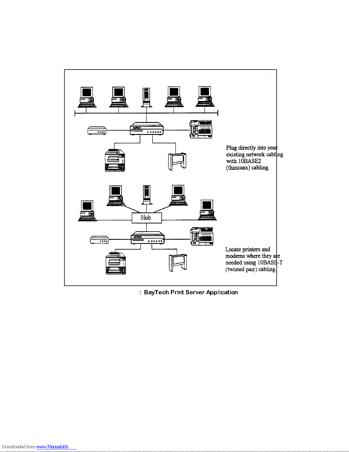
Figure 1
shows an example of a PS-4E used in a Novell based network
using 10BASE2 or 10BASE-T cabling . This example shows 2 printers, a
plotter, and a modem connected to a PS-4E.
IMPORTANT:
In this manual, we assume you know some basic
information about Novell based network s including basic DOS
commands, your network's operat ing system, the NetWare version
number, and the basic funct ions of Novell's PCONSOLE program. I f you
have any questions regarding t he Novell PCONSO LE program, please
refer to your NetWare document ation.
Figure 1
Page 10

4
DEFINITION OF TERMS
Here we will provide a basic definition of the comm on t e r m inology used in
Novell based networks which is utilized in this manual.
10BASE2: IEEE standard f or Thin-Wire Ethernet networks.
Provides 10 Mbps speed, BASEband signalling, 185 meters per
coax segment.
10BASE-T: IEEE standar d for Twisted-Pair Ether net networks. 10
Mbps transmission BASEband signalling, unshielded twisted pair
cable, 100 meters per segment.
BNC: Network connector used with Thin Ethernet cable.
PCONSOLE: Novell Netware Print Console utilit y which allows you
to configure pr int servers, print queues, and control network
printing.
PRINT SERVER: A hardware or software item which services
a network print queue and sends the pr int data to a printer.
TSR: Terminate and Stay Resident - A program which stays in your
PC's memory until either unloaded or the PC is rebooted. Usually
activated via hot key sequence.
VIRTUAL CIRCUIT : A direct connection between two nodes on a
network. This connection allows bidirectional comm unicat ion
between the devices connected to these nodes. Used for dial- out
and dial-in modem communication.
Page 11

SPECIFICATIONS
*PERIPHERAL INTERFACE:
Serial Ports:
EIA-232 (CCITT V.24), -5v mark , +5v
space or EIA-422, -5 to +5 volt differential (TX+,
TX-, RX+, RX-). Hardware (jumper) selectable.
Parallel Ports:
Centronics compatible.
NETWORK INTERFACE:
Ethernet - 10BASE2 (thin coax)
or 10BASE-T (twisted pair) , IEEE 802.3 compliant.
Token Ring: I EEE 802.5 compliant.
NOTE:
If you have a 10BASE2 or 10BASE-T unit and
your network uses a frame type other than 802.3 (e.g.,
Ethernet II or SNAP), please see the
IMPORTANT
statement in
Section 5.1
(Network Interface).
NETWORK OPERATING SYSTEM COMPATIBILITY:
Netware V3.XX and V4.XX .
PERIPHERAL PORT HANDSHAKING*:
CTS/DTR
(EIA-232) or HSI/ HSO (EIA-422); selectable XON/XOFF.
CONNECTORS:
Network Port:
Thin coax - BNC type;
Twisted pair - RJ-45
Token Ring - DB-9F (STP) or RJ-45 (UTP).
Peripheral Ports*:
Serial - RJ-45;
Parallel - DB-25F.
*
- Not applicable to the PS-MIO
Page 12

6
INDICATORS:
All 10BASE-T units have a green Link
Integrity indicator.
PS-4A, PS-4C, and PS-4E:
1 green power LED;
1 red network activity LED; 4 red peripheral port
activity LEDs.
LS MIO:
Network activity LED
*POWER:
9 VDC, 1 A - external (supplied with unit).
DIMENSIONS:
PS-4A, PS-4C, and PS-4E:
7 x 5 3/4 x 1 5/8 inches.
WEIGHT:
PS-4A, PS-4C, and PS-4E:
4 lbs.
PS-MIO:
0.5 lbs.
MOUNTING:
PS-4A, PS-4C, and PS-4E:
Desk-top.
PS-MIO:
Installs in the MIO slot of t he HP Laser Jet
Series IIISi, Series 4, Series 4+, or Series 4Si.
ENVIRONMENT:
0 degrees to 50 degrees C t em per ature;
5% to 95% humidity.
WARRANTY:
One full year.
NETWARE QUEUE SERVICE FEATURES:
Maximum number of queues serviced: 32.
Maximum number of file servers: 32.
Simultaneous port operation.
Queues may be assigned to multiple port s.
Operates with PCONSOLE, CAPT URE, and NPRINT.
*
- Not applicable to the PS-MIO
Page 13

FACTORY-SET POWER-UP DEFAULT CONFIGURATION:
Serial Peripheral Ports (PS-4C and PS-4E only):
Baud rate:
9600 bps.
Data bits:
8 bits.
Stop bits:
1.
Parity:
None.
Handshaking:
DTR.
Virtual circuit connection:
Printer.
Serial interface:
EIA-232.
+Modem Init String:
ATS0=1&C1^M
+Prompt String:
^M^JEnter Workstation ID (Ctrl-C
to Hangup):
+Answer String:
Disabled (blank)
+HangUp String:
~~~+++~~~ATH0^M
+WkStn Init String:
Disabled (blank)
+Access Code:
Disabled
+Timeout:
90 seconds
+Nmbr of Rings:
0
+
- Applicable for dial-in modem communication only if the
port is configur ed as a m odem port.
Network Port:
Print server name:
BT-xxxxxx, where xxxxxx i s the
last six hex characters of the node address. The
default name is labeled on the bott om of the unit.
Update operation mode:
Manual.
NOTE:
If the Update Oper ation Mode is changed
to automatic, the default time interval is 15 minutes.
Queue service interval:
4 seconds.
Page 14

8
USER-PROGRAMMABLE CONFIGURATION:
Serial Peripheral Ports (PS-4C and PS-4E only):
Reconfigurable via BayTech utilit y software except EIA232/EIA-422 peripheral interface which is jumper
selectable. Data is saved in non-volatile memory to
become the new power-up default config uration.
Baud rate:
300, 600, 1200, 2400, 4800, 9600,
19.2k, 38.4k , 57. 6k, 78.6k, 115.2k, 230.4k, or
460.8k bps.
Data bits:
5, 6, 7 or 8 bits.
Stop bits:
1, 1 1/2 or 2.
Parity:
Even, odd or none.
Handshaking:
None, XON/XO FF, or DTR.
Virtual circuit connection:
Printer or modem.
Serial interface:
EIA-232 or EIA-422.
+Modem Init String:
Any string up 46 characters.
+Prompt String:
Any string up 46 characters.
+Answer String:
Any string up to 22 characters
+HangUp String:
Any string up to 22 characters
+WkStn Init String:
Any string up to 22 characters.
+Access Code:
Any string up to 14 characters.
+Timeout:
0 to 650 seconds.
+Nmbr of Rings:
0 to 99 rings.
+
- Applicable for dial-in modem communication only if the
port is configur ed as a m odem port.
Page 15

Network Port:
Utility software is provided which allows you
to install your print server on NetWare V3.X X and V4.XX
file servers. BayTech utility software provides central
management of queues across file servers. Please see
Section 7
for more information on the BayTech utility
software.
Print server name:
You may assign a logical name to
your unit using Novell naming convention (up to 48
characters).
Reset:
Performs software or hardware reset.
Update Operation Mode:
You may program the print
server to update its queue information either
automatically or manually. In automatic mode, the
unit will search for any changes made in its q ueue
assignments every 1 to 99 minutes without
intervention by the user. In manual mode, the unit
will need to be reset after q ueue assignment
information is changed.
Queue Service Interval:
Allows you to program the
time interval at which the BayTech print server
checks the queues f or new print jobs (1 to 4
seconds).
Page 16
10
INSTALLATION/OPERATION OVERVIEW
This section provides basic set up instructions for print server installation
and operation. We will refer to specif ic sections in this manual for more
in-depth instructions on installat ion, operation, and configurat ion. Please
review the following procedure:
Step Instructions
1 GENERAL
Determine what BayTech Print Server model you are installing. The model num ber is
specified on the lower right corner of the rear panel. The model number will have a
hyphenated suffix indicating the network interf ace type. This suffix will be one of the
following:
-CX
(for 10BASE2 thin coax),
-TP
(for 10BASE-T twisted pair), or
-TR
(for
token ring).
Identify which ports are s eri al and whic h are paral l el . Serial ports have RJ-45 modul ar
connectors and parallel ports have DB-25 female connectors. The PS-4A has f our
parallel ports, the P S-4C has four serial ports, and the PS-4E has two parallel and two
serial ports. The Las erS hare PS-MIO installs directly into the MIO slot of the HP
Laserjet IIISi or HP Laserjet 4/4Si printer and does not have parallel or serial ports. If
you are installing a LaserS hare P S-MIO, install the unit into the MIO slot of t he pri nter
as described in
Section 4.5
and proceed to Step 2.
Determine what devices will connect to t he print server and if these devices will
connect as serial or paral l el . Typical devices incl ude pri nters, plotters, modems, or
Tran-x high speed serial-to-parallel converters.
2 CABLING
Cable your print server to the network as described in
Section 5
. If you are install i ng a
LaserShare PS-MIO, proceed to Step 3. Modular adapters are typic al l y required to
connect serial printers, plotters, and modems to the pri nt server. You may connec t a
Tran-x high speed serial to parallel converter to a serial port which will allow a parallel
printer to be located up to 1000 feet away from the print server. Please see
Appendix
A
for the required serial adapter and cable pinouts.
NOTE:
If you will be connecting a Tran-x high speed serial-to-parallel converter to a
serial port on the print server, you must change t he serial interface for t he port to EIA-
422. Please see
Section 4.4
.
Parallel ports require a s tandard male to centronics cable to connect a paral lel printer
to the print server.
Page 17
Step Instructions
3 PRINT SERVER INSTALLATION TO THE NETWORK
Once the BayTech print s erver has been physically connect ed t o the network, it must
be added to the network via software. The print server may be added to the network
and print queues assigned t o the printer ports using Novell P CONSOLE or BayTech's
utility program (PSQMGR). The basic steps to install the print server on the network
are listed below.
a. Log on to the network as a supervis or.
b. Load PCONSOLE or PSQMGR.
c. I nsert the BayTech print server i nto the list of availabl e pri nt servers.
NOTE:
Changes to the default print server name must be made using
PSQMGR or BCON. On networks with m any file servers or with bridges or
routers, it m ay be advantageous to use "Preferred Server" operation (see
Section 7.6.7. 4
).
d. Install and configure where necessary the print server ports that will be
servicing print queues.
NOTE:
Changes to the serial port parameters (baud rate, word size, et c.),
must be conf i gured us i ng PSQMGR or BCON.
e. Define the print queues to be serviced by the print server (if not already
defined).
f. Assign the pri nt server ports to servic e t he appropri ate print queues.
g. Reset the print server using the BayTech utility software or by cycling power.
See
Section 6
for step-by-step network installation instructions using PCONSOLE or
Section 7.7
if using PSQMGR.
Section 7.8
discusses how to c hange the print server
name and/or serial port parameters using BCON. P ri nting is typically accomplished
using Novell's CAPTURE command, NPRINT command, or directly f rom PCONSOLE.
4 MODEM COMMUNICATION
NOTE:
If you are installi ng a LaserShare PS-MIO, skip t hi s step.
If a serial port on the pri nt server is to be used for modem communication, you m ust
use PSQMGR to configure the port as a modem port.
a. Networks users that will be accessing a connected modem for dial-out must
be assigned as
virtual users
. Actual dial-out operation is performed usi ng
the BayTech MSHELL program i n conjunction with a network based
communications package suc h as Procomm P l us® for networks. The
communications package m ust support EXTENDED BIOS 14 CA LLS.
Section 8.1
discusses di al -out modem communication in more detail.
b. Dial-in communication is acc omplished by loading the BayTech MSHELL
program on a local network "hos t" workstation. A remote user may access
the network by first dial i ng i n t o the local modem connected to the print
server. Then a virtual connec t i on i s established between the local modem
and the host workstation. Third party software such as
pcANYWHERE/LAN
allows the remote user to access the network through
the local host workstation.
Section 8.2
discusses di al -i n modem
communication in more detail.
5 If you have any questions, please cal l B ayTech technical support at 1-800-523-2702.
Page 18

12
INSTALLATION
IMPORTANT:
W hen you are installing the BayTech print server, we
assume that you are familiar with Novell printing concept s such as pr int
servers and print queue operation. Please r efer to your Novell NetWare
documentation for m or e information on network print ing concepts.
This section discusses basic installation instructions which include
unpacking, the software utility diskette, power considerations (PS- 4A, PS4C, and PS-4E only), hardware configur at ion for the serial peripheral
ports (PS-4C and PS-4E only), installation into the MIO slot of t he pr inter
(PS-MIO only), and factory default parameters.
Section 5
discusses
cabling,
Section 6
discusses print server installation using PCONSO LE,
and
Section 7
discusses the various commands provided on the utility
diskette and installat ion using PSQMGR.
Before you proceed with installation, you should determine the nam es of
the print queues to be serviced by the BayTech print ser ver. For the PS4A, PS-4C, and PS-4E, you should determine t he num ber and type of
printers that will connect to the unit.
UNPACKING
After opening t he box, check the packing list that com es with your
BayTech print server to ensure that you have received all components
and to determine the specif ic BayTech pr int server model number you
have purchased. At a minimum, you should have received the unit, an
external power supply (PS-4A, PS-4C, and PS-4E models only), a Tconnector for the 10BASE2 ( coaxial) m odels, and this manual with any
applicable addendums. Determine the default print server name which is
located on the bottom of the unit. Also check the unit to m ake certain
that it did not receive damage dur ing shipping. If it em s ar e m issing or
damage did occur, please contact BayTech technical support at 1-800523-2702.
Page 19

BAYTECH SOFTWARE UTILITY DISKETTE
BayTech provides utility software to configure the unique settings of your
BayTech print server. These include the ser ial par am et er s and virt ual
circuit connection for t he peripheral ports (PS-4C and PS-4E only), t h e
update operation mode, the print server name, queue service interval,
and resetting the unit. I n addition, software is provided for modem
communication using virtual circ uit s and third-party EXTENDED BI O S 14
calls communications software.
IMPORTANT:
Copy the BayTech original diskette ont o a blank diskette
and store the original in a safe place. Refer to your operating system's
manual for copying instruct ions.
The software utilit y disk et te provided with your BayTech Print Server
contains a single zipped file: INSTALL.EXE. To install the BayTech
utility software on your network, first log in as a supervisor and use the
DOS COPY command to copy INST ALL ont o a public dir e ct or y on a file
server which the supervisor and users have access to. Next, type
INSTALL
from the public subdirect or y prom pt . This command will
expand seven files onto the public subdirectory: PSQMGR.EXE,
BCON.EXE, MSHELL.EXE, DIAL.EXE, MOPEN.EX E, MCLOSE.EXE and
BAY.TCH.
PSQMGR is a menu-driven configur ation program equivalent to Novell
PCONSOLE. PSQMGR is used to prog ram the unique feat ures of the
BayTech print server as well as set up other print servers, m anage print
queues, control network pr inting, and view information about network
printing. BCON is a command line utility that perfo r m s cer tain functions
of the PSQMGR program from a DOS prompt. The BAY.T CH file is
called by the PSQMGR program when it is loaded.
Page 20

14
MSHELL is a memory resident program used f or dial-out and dial-in
modem communication. DIAL allows modem select ion from a menu for
dial-out modem communication and is used t o assign workstation IDs for
dial-in modem communication. T he MOPEN and MCLOSE programs are
used for dial-out modem com m unication to select a network modem and
disconnect from the m odem r espectively. The operational functionality of
the software is discussed in
Section 7
and
Section 8
.
POWER
NOTE:
This section does not pertain to the PS-MIO since this unit draws
its power from the LaserJet printer. If you are installing a PS-MIO, please
proceed to
Section 4.5
.
IMPORTANT:
Do not power up your BayTech print server until all
external cables have been connected (see
Section 5
). If you will be using
PCONSOLE, do not power up the BayTech print server unt il after the unit
has been added to your network as a print server and the relevant pr int
queues assigned to it (see
Section 6
). If you will be using the BayTech
utilities (see
Section 7
), you must power up the BayTech print server af ter
all external cables have been connected.
The PS-4A, PS-4C, and PS- 4E m odels r equire external DC power. The
external power supply provided with your print server supplies 9 VDC at 1
A. To apply power, first plug t he DC jack of the external power supply
into the
POWER
receptacle on the rear of t he unit and then plug the AC
connector into an AC socket. Next, posit ion t he on/off switch on the rear
panel to the
ON
position. Power-on is indicated on the fr ont panel by the
illuminating of a green LED.
WARNING:
Do not connect or disconnect the DC jack from the BayTech
print server while the AC connector is plugged int o an AC socket. Power
should be disconnected anytime cables are to be installed or removed.
Make sure the power is disconnected before removing t he cover and
attempting to m ake any internal changes such as changing the EPRO M.
Page 21

If you are installing a PS-4A, please proceed to
Section 4.6
.
PS-4C AND PS-4E: SERIAL INTERFACE
SELECTION
Serial ports on the PS-4C and PS-4E may use either EIA-232 or EIA-422
serial interface. The serial interface is configured via hardware jumper
settings. Most serial printers and plotters support EIA-232 serial interface
(default). This generally limits the serial speed and ma ximum cable
distance. EIA-422 serial interface allows you to run at high speeds (up to
460,800 bps) over long cable distances (up to 1000 feet). Some printer s
may be equipped with an EIA-422 port. BayTech supplies a high speed
EIA-422 serial to parallel converter (Tran-x SP-01) which would allow
your printer to operate in parallel up t o 1000 feet at 460,800 bps.
NOTE:
If you will be connecting a Tran-x high speed converter , you must
reconfigure t he ser ial int er face of the port( s) t o EIA-422. If you will be
connecting any EIA-232 serial printers, plotters, or modems, you must
use EIA-232 serial interface (default).
Serial interface selection should be done before any other hardware
installation such as connecting cables or applying power. Once you have
made any necessary changes for serial interface, you may review the
user-programm able features (see
Section 4.6
).
If you must reconf igure the serial interf ace for any of the peripheral port s
on the PS-4C or PS-4E, you will need a phillips-head screwdriver. Please
use the following instructions:
1.
IMPORTANT:
Remove power from the unit by first unplugging
the AC converter from the AC socket and then removing the DC
jack from t he
POWER
receptacle.
2. Remove the cover of the unit by first unscr ewing t he 2 scr ews
located on the front panel with the phillips- head scr ewdriver.
Next, remove the front panel and then slide the top panel off.
Page 22
16
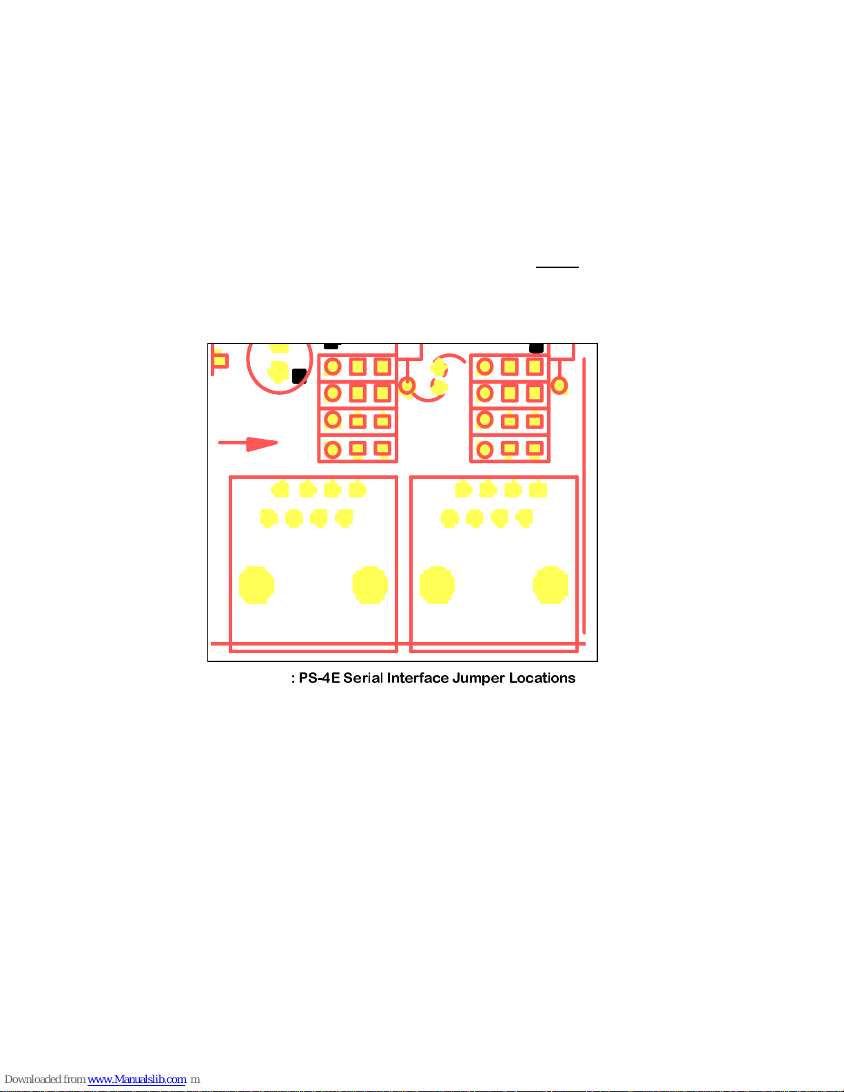
3. Refer to
Figure 2
below and locate the jumper locations for EI A232/EIA-422 serial interface selection. The jumper locat ions ar e
adjacent to the respective serial ports . Each jumper location has
three pins: a center or common pin, a pin marked
232
, and a pin
marked
422
. Each port is configured for EIA-232 or EIA-422
serial interface by positioning four jumpers to connect t he
common pin and the
232
pin for EIA-232 (default) or the common
pin and the
422
pin for EIA-422.
IMPORTANT:
For each port, all jumpers must be installed either
to the
232
or
422
side for the desired serial interface.
4.
Procee
d to
Sectio
n 4.6
.
422
232
422
232
P3
P4
C46
C45
Figure 2
Page 23
PS-MIO PHYSICAL INSTALLATION
Please see
Section 4.5.1
if you are installing the PS-MIO into an
HP LaserJet Series IIISi or
Section 4.5.2
if installing the PS-MIO
into an HP LaserJet Series 4.
HP LASERJET SERIES IIISI INSTALLATION
The PS-MIO installs inside the HP Laserjet IIISi in the place of the
existing interface or adapter card. The interface card has a
Centronics parallel port and an EIA-232/EIA-422 serial port as
shown in
Figure 3
below.
Figure 3: HP Laserjet Series IIISi
Interface Card
Page 24

18
CAUTION:
The LaserJet interface card and the PS-MIO contain
electrical components which are susceptible to damage from static
electricity. To avoid damage, either use an anti-static wrist strap
and a grounding mat similar to those included in the Electrically
Conductive Field Service Grounding Kit (HP 9300-0933) or touch
the surface of the bubble wrap the PS-MIO comes shipped in and
any bare sheet metal surface on the rear of the printer. Avoid
moving about the work area, especially if it is carpeted. Handle the
interface card and the PS-MIO carefully at all times. Never flex or
put excessive pressure on either device. Avoid touching electrical
components.
Use the following instructions to install the PS-MIO into your HP
LaserJet IIISi:
1.
IMPORTANT:
Remove power from the printer by
positioning the on/off switch to the "0" (off) position and
unplugging the electrical cord from the AC outlet.
2. Remove any interface cables connected to the parallel or
serial ports of the interface card. Next, loosen the two
thumbscrews that secure the interface card into the I/O slot.
You may need a flat head screw driver to initially loosen
these screws. Remove the interface card from the I/O slot
by pulling on the two thumbscrew posts with a moderate
amount of pressure. Place the interface card in a safe place
such as an anti-static bag.
3. Install the PS-MIO into the I/O slot with the 48-pin connector
at the bottom of the board by sliding it along the card guides
inside the slot while holding the thumbscrew posts. You
should feel the connector on the PS-MIO board insert into
the connector inside the I/O slot. Tighten both thumbscrews
with the flat head screw driver.
Page 25

4. Apply power to the printer. When the printer completes its
power-up self test, take the printer off-line and hold the
Test
key down until "SELF TEST" appears on the display and
then release the
Test
key. The printer should print out a
SELF TEST
page which will include information for the PS-
MIO as follows:
MIO CONFIGURATION
Bay Technical Associates Inc.
Version 1.00
LaserShare = PS-MIO
NAME =
XXX
ADDRESS =
YYY
XXX is the print server name and YYY is the print server
node address. This menu will confirm the installation of the
PS-MIO. Proceed to
Section 4.6
.
Page 26
20
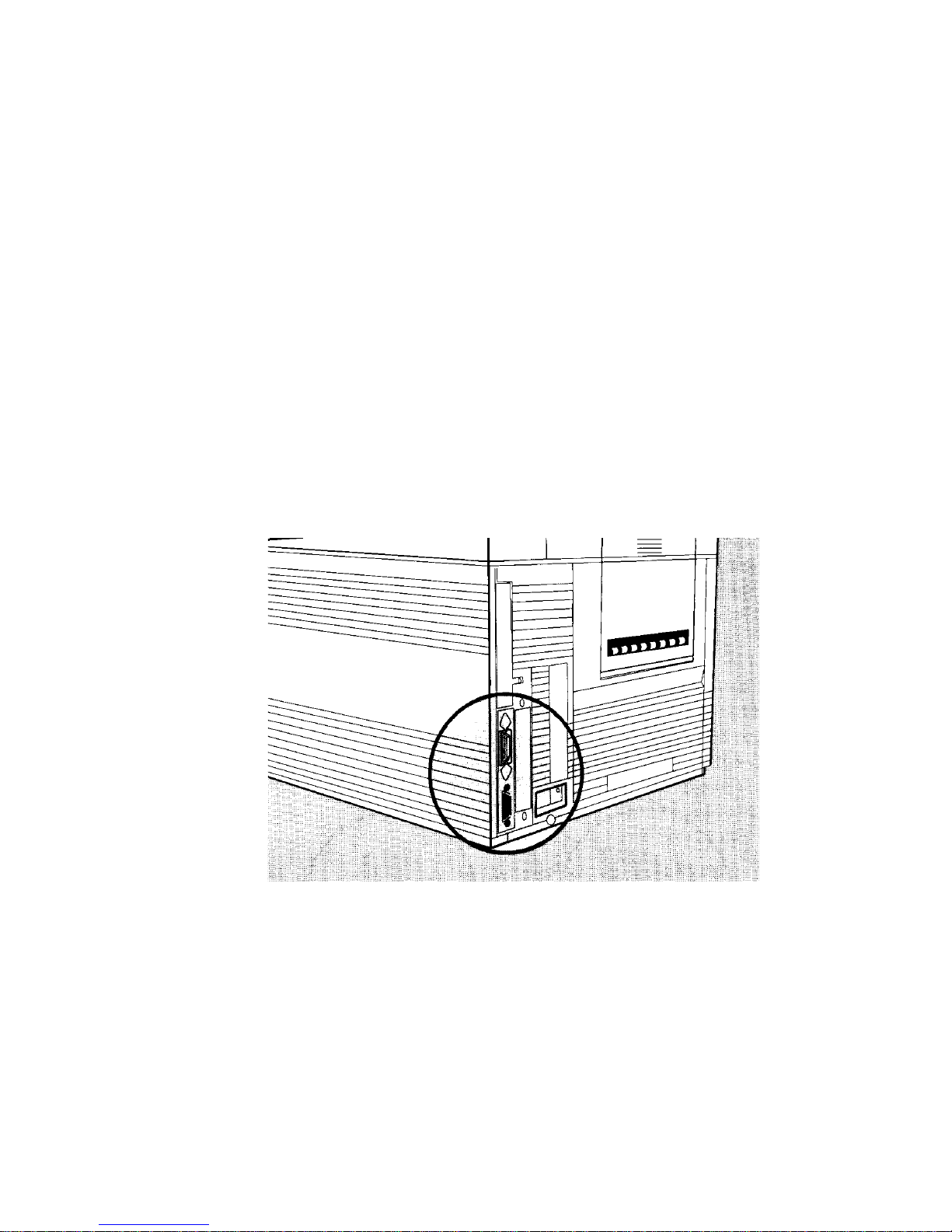
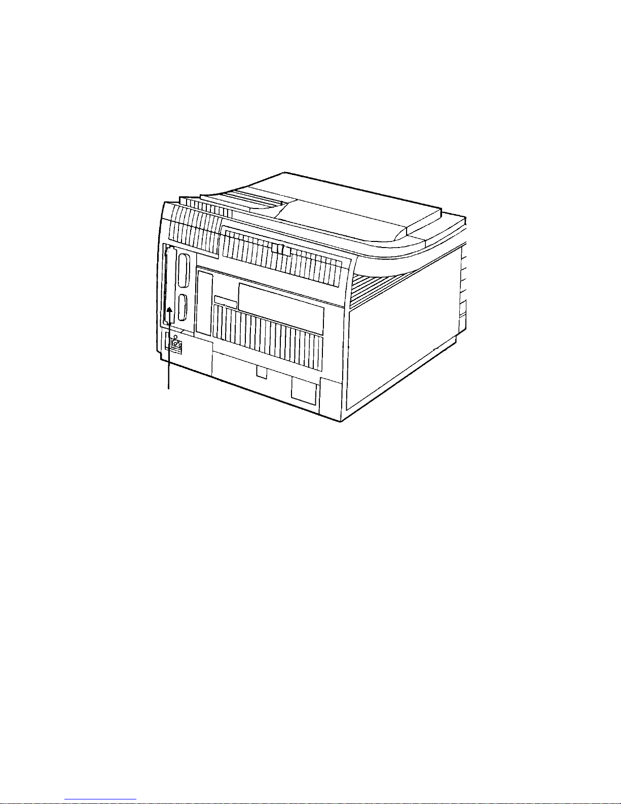
HP LASERJET 4 AND 4SI INSTALLATION
The PS-MIO installs inside the Modular I/O (MIO) slot. Please see
Figure 4
below. You may use the existing Centronics parallel and
EIA-232/EIA-422 serial ports in addition to the ports on the PSMIO.
CAUTION:
The PS-MIO contains electrical components which are
susceptible to damage from static electricity. To avoid damage,
either use an anti-static wrist strap and a grounding mat similar to
those included in the Electrically Conductive Field Service
Grounding Kit (HP 9300-0933) or touch the surface of the bubble
wrap the LaserShare comes shipped in and any bare sheet metal
surface on the rear of the printer. Avoid moving about the work
area, especially if it is carpeted. Handle the PS-MIO carefully at all
times. Never flex or put excessive pressure on the card. Avoid
touching electrical components.
Figure 4: HP LaserJet Series 4 MIO Slot
Page 27

Install the PS-MIO into your HP LaserJet 4 as follows:
1.
IMPORTANT:
Remove power from the printer by
positioning the on/off switch to the "0" (off) position and
unplugging the electrical cord from the AC outlet.
2. Remove any interface cables connected to the parallel or
serial ports. Next, remove the metal plate covering the MIO
slot or any existing MIO card by loosening the two
thumbscrews that secure the plate or card to the MIO slot.
You may need a flat head screw driver to initially loosen
these screws. Remove the plate or card from the MIO slot
by pulling on the two thumbscrew posts with a moderate
amount of pressure. Place the plate or card in a safe place.
3. Install the PS-MIO into the I/O slot with the 48-pin connector
towards the top of the board by sliding it along the card
guides inside the slot while holding the thumbscrew posts.
You should feel the connector on the PS-MIO card insert
into the connector inside the I/O slot. Tighten both
thumbscrews with the flat head screw driver.
4. Apply power to the printer. When the printer completes its
self test, take the printer off-line and press
Menu
key
repeatedly until "TEST MENU" appears on the display.
Press the
Item
key once and the display will show "SELF
TEST". Press the
Enter
key and the printer should print out
a
SELF TEST
page which will include information for the PS-
MIO similar to the following:
AUX IO MENU
LASERSHARE = PS
Bay Technical Associates Inc.
Version 1.00
LaserShare = PS-MIO
NAME =
XXX
ADDRESS =
YYY
This menu will confirm the installation of the PS-MIO.
Page 28

22
FACTORY DEFAULT CONFIGURATION
The
[ Factory ]
selection under the "BayTech PrintServer Setup"
menu in PSQMGR (see
Section 7.6.7
) will reconfigure the print
server to the factory default values as follows:
*
Baud Rate:
9600 bps.
*Data bits:
8 bits.
*Stop bits:
1.
*Parity:
None.
*Handshaking:
DTR.
*Virtual circuit connection:
Printer.
Print server name:
BT-xxxxxx, where xxxxxx is the
last six hex characters of the node address. The
default name is labeled on the unit.
Operation mode:
Manual.
Queue service interval:
4 seconds.
*
- Serial ports on the PS-4C and PS-4E only.
The
[ Factory Setup ]
selection under the "Port X Modem Setup"
menu in PSQMGR (see
Section 8.2
) will reset the dial-in modem
parameters on PS-4C and PS-4E modem ports to the following
factory default values:
Modem Init String:
ATS0=1&C1^M
Prompt String:
^M^JEnter Workstation ID (Ctrl-C
to Hangup):
Answer String:
Blank
HangUp String:
~~~+++~~~ATH0^M
WkStn Init String:
blank (disabled)
Access Code:
Disabled
Timeout:
90 seconds
Nmbr of Rings:
0
Page 29

If the factory default parameters are not satisfactory for your
application, you must use the BayTech software utilities to
reconfigure the BayTech print server. If the default parameters are
satisfactory, there is no need to use the BayTech software utilities.
You may use PCONSOLE to add the BayTech print server on the
network and to assign print queues to the ports as described in
Section 6
.
NOTE:
Even if the factory default settings are satisfactory, you
may still use the BayTech software utilities to add the BayTech
print server to the network. The primary advantage to using the
BayTech utility is that it automatically informs a ll selected file
servers the BayTech print server has been added. Otherwise, you
would have to update the desired file servers individually. Other
advantages of the BayTech utility software are described in
Section
7.1
.
CABLING
Section 5.1
discusses the hardware interface to the network and
Section 5.2
explains how to cable your printers or plotters to the
PS-4A, PS-4C, or PS-4E.
CAUTION:
Power should be removed anytime cables are installed.
NETWORK INTERFACE
The network port of your BayTech print server is equipped with a
10BASE2 (coax) connector for - CX m odels, a 10BASE-T (modular)
connector for -TP models, or a DB-9F (STP)/ RJ- 11 ( UTP) connector for TR models. The specif ic net work interface type is indicated on the lower
right corner of the back panel. For example,
PS4E-CX
specifies a PS-4E
with a 10BASE2 coax network interface. See
Section 5.1.1
for network
interface instruct ions for -CX models,
Section 5.1.2
for -TP models, or
Section 5.1.3
for -TR m odels.
Page 30
24
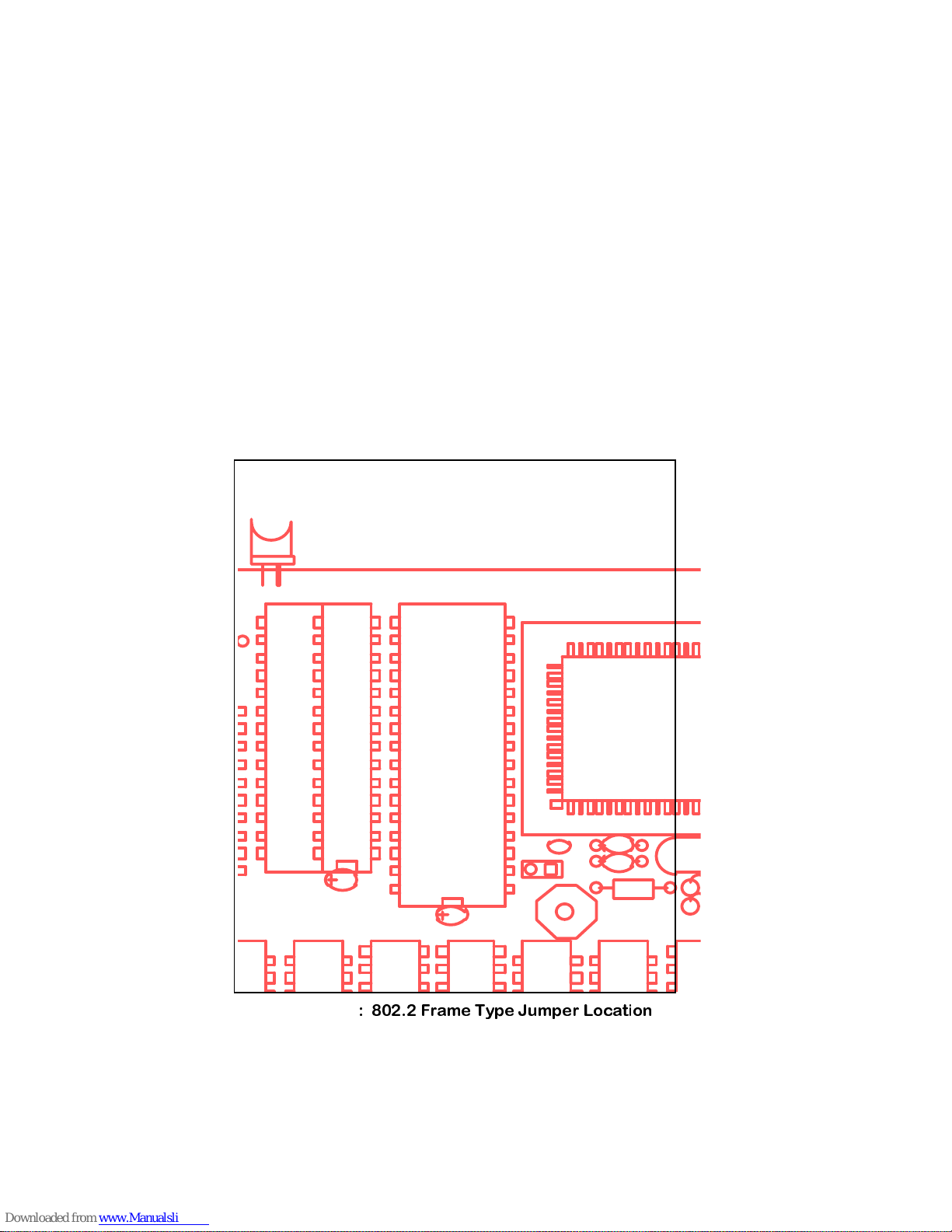
IMPORTANT:
BayTech 10BASE2 (-CX) and 10BASE-T (-TP) print
servers use a frame type of 802.3. If your network uses a frame
type other than 802.3 (e.g., Ethernet II or SNAP), you must load an
additional frame type for your network card in the file server. This
is accomplished via the LOAD command. Please refer to your
Netware System Administration documentation for more
information on loading a LAN driver more than once. You may
hardware configure the print server to support the 802.2 frame type
without the need to add another frame type to your file server. This
is done by removing the jumper at
JP2
. Once this jumper is
removed, the unit will only recognize 802.2 frames and will no
longer recognize 802.3 frames. Please see
Figure 5
on the
following page for the location of this jumper.
LED1
C47
C48
C49
JP1
R1
U1
U2
U3
C1
C2
Y1
1
Figure 5
!"! #
Page 31

10BASE2 (COAX) CONNECTION
The network port of a BayTech -CX print server connects to any
BNC connector on the network cable. BayTech provides a Tconnector for this purpose. Please see
Figure 6
below.
PARALLEL PORTS
2
1
3
SERIAL PORTS
4 OFF
0
1
ON
POWER
MADE IN USA
NETWO
R
POWER
9VDC
+ -
PS-4E
-
Figure 6
: PS-4E Connection to Network
Page 32

26
If you are installing a PSMIO-CX, proceed to
Section 6
if using
PCONSOLE to add the BayTech print server to the network or
Section 7
if using the BayTech software. If you are installing a
PS4C-CX or PS4E-CX, proceed to
Section 5.2
. If you are installing
a PS4A-CX, proceed to
Section 5.3
.
Page 33

10BASE-T (MODULAR) CONNECTION
If your network uses 10BASE-T, RJ-45 connectors, connect an RJ45 cable between the modular
NETWORK
port and the network
hub. The modular
NETWORK
port is defined as DTE (i.e., Pin 1 is
TD+, Pin 2 is TD-, Pin 3 is RD+, and Pin 6 is RD-). Most RJ-45
network hubs will require a straight cable.
The
LINK
(link integrity) LED on the back panel will illuminate if
there is a good connection between the BayTech print server and
the hub.
If you are installing a PSMIO-TP, proceed to
Section 6
if using
PCONSOLE to add the unit to the network or
Section 7
if using the
BayTech software.
From the factory, 10BASE-T models come configured to use Un-
shielded Twisted Pair Cabling (UTP). If your application uses
Shielded Twisted Pair Cabling (STP), you must configure a jumper
on your print server. The required jumper number is
JP5
for the
PS-4A and PS-4E and/or
JP6
for the PS-4C.
Appendix E.3
shows
the location of this jumper for the PS-4A Print Server,
Appendix E.4
shows the jumper location for the PS-4C Print Server Plus, and
Appendix E.5
shows the jumper location for the PS-4E Print Server
Plus.
If you must change this jumper to accommodate STP cabling, you
will need a phillips-head screwdriver. Use the following procedure:
1.
IMPORTANT:
Remove power from the print server by
unplugging the AC plug from the AC outlet and DC plug from
the
POWER
receptacle.
2. Remove the cover of the unit by first unscrewing the 2
screws located on the front panel with the phillips-head
screwdriver. Next, remove the front panel and then slide the
top panel off.
Page 34

28
3. If you have a PS-4A or PS-4E, locate
JP5
(see the
appropriate drawing). This two-position jumper will connect
two pins furthest away from
U34
.
4. If you have a PS-4C, locate
JP6
(see the appropriate
drawing). On the PS-4C Print Server Plus, this two-position
jumper will connect two pins furthest away from
U53
. On the
PS-4C Print Server, this two-position jumper will connect two
pins furthest away from P5.
5. Replace the cover.
If you are installing a PS4C-TP or a PS4E-TP, proceed to
Section
5.2
. If you are installing a PS4A-TP, proceed to
Section 5.3
.
TOKEN RING CONNECTION
BayTech print server -TR models have two connectors on the rear
of the unit for interface to the Medium Access Unit (MAU). A DB-9
connector is used for shielded twisted pair connections (STP) and
an RJ-11 connector is provided for unshielded twisted pair
connections (UTP).
WARNING!!!:
Do not use both the UTP and STP connectors
simultaneously as permanent damage to the unit will result.
Refer to
Section 5.1.3.1
if you will be using STP cab ling or
Section
5.1.3.2
if you will be using UTP cab ling. After you have cabled the
BayTech print server to the network, if you are in sta lling a PSMIOTR, proceed to
Section 6
if using PCONSOLE to add the print
server to the network or
Section 7
if using the BayTech software. If
you are installing a PS4C-TR or a PS4E-TR, proceed to
Section
5.2
. If you are installing a PS4A-TR, proceed to
Section 5.3
.
Page 35

TOKEN RING STP CABLING
A shielded PC Adapter cable (IBM part 6339098 or equivalent) can
be used to connect the unit directly to the MAU. The STP
connector should be used for type 1 or type 2 cables in systems
having wiring closets. Please see
Figure 7
below for the
recommended cabling diagram.
TOKEN RING UTP CABLING
An unshielded PC adapter cable consisting of 2 unshielded twisted pairs
with an RJ-11 plug at each end can be used. The UTP connect or should
be used for type 3 (4-conductor or 6- conductor) wiring connections.
Please see
Figure 8
below for the recommended cabling diagram
.
Figure 7
$%% &'(
Figure 8
$%% ) &'(
Page 36

30
PS-4C AND PS-4E: SERIAL PERIPHERAL
INTERFACE
IMPORTANT:
Before you proceed with cabling your serial peripherals to
the PS-4C or PS-4E, you must verif y that t he equipment supports either
EIA-232 or EIA-422 serial inter face. In addition, you must know the
connector type and the pin/signal definitions for your equipment . If you
wish to connect a parallel printer to the PS-4C, you must use a Tran-x
SP-01 serial-to-parallel converter. You may also use Tran-x on the serial
ports of the PS-4E to connect a parallel printer located mor e t han 25 feet
from the unit ( up t o 1000 feet).
Serial ports on the PS-4C and PS-4E have RJ-45 ( 8-wire) connectors
which accept RJ-11 (4-wire) or RJ-12 (6-wire) connectors.
Figure 9
and
Figure 10
on the following page are drawings of an RJ-45 receptacle and
plug. The pin/sig nal definition for each port is determined by the serial
interface you are using
.
Figure 9: RJ-45 Receptacle Figure 10: RJ-45 Plug
If the serial ports of the PS-4C or PS-4E are set for EIA-232 serial
interface (default) and you will be connecting a device that uses
EIA-422 serial interface (e.g., Tran-x), you should reconfigure the
port for EIA-422 before connecting any cables. Please see
Section
4.4
.
NOTE:
Most serial printers, plotters, and modems use EIA-232
serial interface and do not have RJ-45/RJ-11 modular connectors.
Adapters are required to convert from DB-25 connectors to
modular connectors. BayTech has a complete line of adapters and
cables that will make your installation quick and trouble free.
Page 37

Serial ports on the PS-4C and PS-4E utilize the following pins and
signals for communication:
RJ-45 PINOUT INFORMATION
PIN SERIAL INTERFACE DIRECTION DESCRIPTION
RJ-11 RJ-12 RJ-45 EIA-232 EIA-422
---- ---- 1 DTR +9V Output
232:
Data Terminal
Ready. Output
handshake to
modem.
422:
External power
signal for remot e
Tran-x SP-01/SP-02
---- 1 2 GND GND ---- Signal Ground
1 2 3 RTS TX+ Output
232:
Request To
Send
422:
Transmit Data
(+)
2 3 4 TX TX- Output
232:
Transmit Data
422:
Transmit Data
(-)
3 4 5 RX RX- or HSI- Input
232:
- Receive Data
422:
Receive Data (-)
(XON/XOFF mode)
or Handshake In (-)
(hardware mode)
4 5 6 RI RX+ or HSI+ ----/Input
232:
Ring Indicator
from modem
422:
Receive Data
(+) (XON/XOFF
mode) or Handshake
In (+) (hardware
mode)
---- 6 7 DCD NU Input/----
232:
Data Carrier
Detect from modem
422:
No Connection
---- ---- 8 CTS NC ----
232:
Clear To Send
422:
Not Used
Please see
Appendix A
for printer cabling and adapter information.
If you are installing a PS-4C, proceed to
Section 6
if using
PCONSOLE to add the print server to the network or
Section 7
if
using the BayTech software.
Page 38

32
PS-4A AND PS-4E: PARALLEL PRINTER
INTERFACE
Parallel ports on the PS-4A and PS-4E have DB-25 female
connectors. A DB- 25 male-to-Centronics cable is required
between each printer having a Centronics connector and the
BayTech print server (same as IBM PC to Centronics cable).
The pin layout for the DB-25 connector is similar to IBM PC parallel
connector and uses the following signals:
PARALLEL PORT PIN DEFINITION
Signal Name DB-25 Pin #
- Strobe 1
+ Data Bit 0 2
+ Data Bit 1 3
+ Data Bit 2 4
+ Data Bit 3 5
+ Data Bit 4 6
+ Data Bit 5 7
+ Data Bit 6 8
+ Data Bit 7 9
- Acknowledge 10
+ Busy 11
+ P. End (Out of Paper) 12
+ Select 13
- Auto Feed 14
- Error 15
- Initialize Printer 16
- Select Input 17
Ground 18-25
Please see
Appendix A.4
for paralle l printer cabling information.
Page 39

PRINT SERVER INSTALLATION USING
PCONSOLE
This section addresses setting up your BayTech print server on the
network using PCONSOLE. You should have a basic knowledge of
NetWare, particularly the PCONSOLE program. If you are
unfamiliar with NetWare, you should contact a local dealer for
installation assistance. You may use PCONSOLE or the BayTech
utility software to add the BayTech print server to your network. If
you wish to use the BayTech software, please see
Section 7
.
NOTE:
If your application requires that you change any of the
BayTech print server's default parameters (see
Section 4.6
), you
must use the BayTech software utilities. The BayTech p rint server
will not read any configuration changes made in PCONSOLE (i.e.,
print server name and serial parameters). If you use PCONSOLE
to add the BayTech print server to the network and assign print
queues, a quick way to change these parameters is to use the
BCON.EXE command line utility (see
Section 7.8
).
Follow the steps below to add the BayTech print server to the
network using PCONSOLE.
1. Log in as a Supervisor and run Novell PCONSOLE.
2. Create the print server as follows:
a. Highlight
Print Server Information
followed by ENTER.
b. Press INSERT and then enter the default print server
name in the "New Print Server Name" box and press
ENTER. The print server name is added to the "Print
Servers" list.
IMPORTANT:
You must initially enter the default
print server name (see
Section 4.6
). If you wish to
change the default name, you must use the BayTech
utility software after installing the BayTech print
server (see
Section 7.8
).
Page 40

34
c. Repeat this step for every BayTech print server you
wish to install. Return to the PCONSOLE main menu.
3. If the desired print queues do not exist, define the print
queues to be serviced by the BayTech print server by first
highlighting
Print Queue Information
followed by ENTER.
Next, strike the INSERT key followed by the desired queue
name. You would typically create one print queue for each
printer connected to the BayTech print server. Return to the
PCONSOLE main menu.
4. Assign the BayTech print server to service print queues as
follows:
a. Highlight "Print Server Information" from the main
menu and press <ENTER>.
b. Select the print server name entered in Step 4 from
the "Print Servers" list.
c. Select "Print Server Configuration" from the "Print
Server Information" menu.
d. Select "Printer Configuration". Define the printers for
the BayTech print server by selecting the desired
printers from the "Configured Printers" list. For each
printer, use the "Defined elsewhere" type.
e. Select "Queues Serviced by Printer" from the "Print
Server Configuration" menu.
f. Select a printer from the "Defined Printers" list.
NOTE:
"Printer 0" corresponds to Port 1 of the
BayTech print server, "Printer 1" corresponds to Port
2, "Printer 2" corresponds to Port 3, and "Printer 3"
corresponds to Port 4. Although PCONSOLE shows
printers from 0 to 15, the BayTech print server will
only recognize Printer 0 to Printer 3 for the PS-4A,
PS-4C, and PS-4E and Printer 0 for the PS-MIO.
i. Press <INSERT> at the "File
Server/Queue/Priority" box.
Page 41

ii. Select a queue from the "Available Queues"
list.
iii. Enter the desired priority level 1 to 10 with 1
being the highest priority.
iv. Repeat items i through iii for each queue to be
serviced by the selected peripheral port.
v. Select any other printers on the BayTech print
server which will service print queues and
repeat items i through iv.
5. Repeat Step 4 for each BayTech print server you have
installed on the network and then exit PCONSOLE.
6. Activate the BayTech print server by applying power to it.
7. The installation is complete. You should use the BayTech
software utility if you need to change any of the BayTech
print server settings. Refer to
Section 7.8
for a detailed
explanation of the various utility commands. Otherwise, you
should be able to print through the BayTech print server
using normal NetWare print commands (e.g., CAPTURE,
NPRINT, or PCONSOLE). BayTech print server will support
all of PCONSOLE's Print Server/Control functions. Please
see
Section 8
for modem sharing instructions and
Section 9
for a definition of the LEDs on the front panel. If you
experience any difficulties, please refer to
Appendix C
(Troubleshooting).
Page 42

36
PRINT SERVER SOFTWARE - PSQMGR
The utility software provided with your print server includes a menudriven configuration program (PSQMGR). Please see
Section 7.1
through
Section 7.6
for detailed information on PSQMGR.
Section
7.7
discusses quick installation using PSQMGR. A command line
version of PSQMGR (BCON.EXE) is provided allowing you to
perform some basic PSQMGR functions from a DOS prompt. You
may configure the BayTech print server name, serial printer port
configuration, virtual circuit connection, line delay, and update
operation mode with BCON.EXE (see
Section 7.8
).
NOTE:
If you are adding your BayTech print server to the network
using PSQMGR, proceed to
Section 7.7
(Quick BayTech Print
Server Installation Using PSQMGR) for step by step instructions. If
you have already added the unit to the network and assigned print
queues to it using PCONSOLE, you may wish to use BCON.EXE to
make any desired changes to the print server parameters.
GENERAL INFORMATION
PSQMGR is a menu-driven general print server management utility
which is also used to configure the BayTech print server. On any
BayTech print server, you may change such items as the print
server name, the parameters of serial printer ports, the queue
service interval, and the update operation mode. In addition to
programming these unique features for the BayTech print server,
PSQMGR may be used to perform the same print server
management functions as Novell PCONSOLE (i.e., install any print
server, set printer configuration, assign print queues, etc.).
PSQMGR will automatically determ ine all file servers, print servers,
and print queues on the network when it is executed and will
update such information as printer configuration and queue files on
the selected file servers. You may view this information on either a
file server or print server basis. This data may be accessed by the
PCONSOLE utility if required.
Page 43

PSQMGR provides a user-friendly menu convention that will allow
you to use a mouse. PSQMGR will allow you to manipula t e up to
32 file servers simultaneously and change file servers from most of
the menus. The file servers being serviced and file servers to be
serviced appear in adjacent menus.
W hen installing a new print server, PSQMGR gives you the ability
to view all un-installed advertising print servers and will
automatically show you all file servers on which the print server
may be installed. You may selectively delete a print server on
various file servers from one menu. Also, when you delete a print
server, PSQMGR will delete the bindery item and all relevant
directories so there will be no unused directories on the file
server(s).
You may manipulate print server operator and user lists for the
same print server on multiple file servers from one menu in
PSQMGR. This is also true for print queue operator and user lists.
W ith PSQMGR, you may select a password for the print server
that will be registered simultaneously on all file servers on which
the print server is installed. When changing printer configurations,
if a printer has different configuration information on separate file
servers, PSQMGR will automatically make the necessa ry
corrections ensuring printer configuration files on all selected file
servers are consistent.
W hen assigning print queues using PSQMGR, changing file
servers will allow you to view all queues assigned to a printer port.
Queue assignment may be performed across file servers. You
may use the same queue name on different file servers.
Page 44

38
EXECUTION, CONVENTIONS, AND
INFORMATION MENU
IMPORTANT:
The print server should be connected to the network
and powered on before using PSQMGR. You should execute
PSQMGR from a workstation with supervisory privileges to make
changes to the print server and the network. PSQMGR should be
located on a public subdirectory.
To execute PSQMGR, type
PSQMGR
from the network prompt.
An introductory menu will appear for a few seconds showing the
BayTech logo, program name, and revision number. Next, the
"Information" menu will appear as follows:
This menu is used for ident ification purposes only. The "Information"
menu will appear when you first enter into PSQMGR and when you select
the (About) symbol in the upper left corner of your screen. Press the
<ESC> or <ENTER> keys or click on t he [] symbol in the upper left
corner of the "I nformation" menu with your mouse to close this menu.
Page 45

NOTE:
In this manual, menu titles will be shown in quotes (e.g., "Menu
Title"). Menu choices will be shown in italics (e.g.,
Menu Choices
).
PSQMGR allows you to use several conventions to highlight and select
various menu items. The easiest way is to use a mouse to click on the
desired item. Individual menu items may also be selected by pressing
the
ALT
key and the letter associated with the desired it em
simultaneously. To highlight items such as file/print servers and print
queues, you may use the arrow keys if you do not have a mouse. Some
menu choices will prompt you to type in the relevant inform at ion ( e. g.,
print server name). Some m enu choices will display a drop-down menu.
You may highlight the desired item and press <ENTER> or double click
with the mouse
.
FILE SERVER MENU
W hen you initially close the "I nformation" menu or select
File Server
from
the main menu (see
Section 7.4
), the "File Servers" m enu will appear as
follows:
Page 46

40
Items in this menu allow you to attach to file servers and log out of
additional file servers similar to the "Change File Server" function
in PCONSOLE. The list on the left displays the file servers to
which you are currently attached. The available file servers to
which you may attach are displayed in the list on the right.
IMPORTANT:
You must be logged-in to a file server to perform
PSQMGR tasks for that file server.
To log-in to a file server in the "Available Servers" list, first select
the "Available Servers" list. Next, highlight the desired file server
and select
[ Login ]
. The "Login" menu will appear. Type in your
user name followed by any applicable password. The selected file
server will appear in the "Logged Servers" list.
To log out of a file server in the "Logged Servers" list, first select
the "Logged Servers" list. Next, highlight the desired file server and
select
[ Logout ]
. A "Confirm" menu will appear. Select
Yes
to log
out of the selected file server. To exit out of the "File Servers"
menu, select
[ Exit ]
.
Page 47

MAIN MENU
W hen you close the "File Servers" menu, the main menu will
appear as follows:
The main menu gives you five choices: the (About) symbol,
File
Server, Queues, Print Server, Modem Groups
, and
Exit
. The
choice will display the "Information" menu as shown in
Section 7.2
.
The
File Server
choice is discussed in
Section 7.3
, the
Queues
choice is discussed in
Section 7.5
, and the
Print Server
choice is
discussed in
Section 7.6
. Select
Exit
to exit PSQMGR.
NOTE:
You may select
File Server
from the main menu by typing
F
if the cursor is displayed or
ALT-F
if the cursor is not displayed.
Likewise, you may select,
Queues
by typing Q (or
ALT-Q
),
Print
Server
by typing P (or
ALT-P
), or
Exit
by typing X (or
ALT-X
). Type
the F10 key if you wish to display the cursor.
Page 48

42
QUEUES MENU
If you select
Queues
from the main menu, the "Queues" menu will
appear as follows:
Items in this menu perform the same funct ions as " Pr int Q ueue
Informat ion" in PCO NSO LE. The list on the left displays t he pr int queues
currently defined on the f ile server shown in the
Current File Server:
field.
You may change the current f ile server by clicking on the
symbol
shown adjacent to the
Current File Server
field or by typing
ALT-C
. The
list of logg ed file servers will appear. Highlight t he desired file server and
then press <ENTER> or double click.
On the right are eight possible choices:
[ Insert ], [ Delete ]
,
[ Oprs ], [ Users ], [ Entries ], [ Info ], [ Servers ]
, and
[ Exit ]
. The
functionality of these choices is descr ibed in
Section 7.5.1
through
Section 7.5.4
. The
[ Exit ]
selection is used to exit the "Queue Menu". If
not using a mouse, use the <T AB> key to move between fields or type
the associated letter f or the desired choice (e.g., I for
[ Insert ]
).
Page 49

QUEUES - [ Insert ]
If you select
[ Insert ]
from the "Queues" menu, you may create a
print queue. The "Insert Queue" menu will appear as follows:
This menu shows
Queue Name, Installed
file servers, and
Available
file servers. Type in the name of the print queue to be
created in the
Queue Name
field and select the
Available
file server
list.
Highlight the desired file server and select
[ Add <= ]
. Repeat this
procedure for each file server to which you wish to add the new
print queue. If you add the new queue to a file server in error,
highlight the file server in the
Installed
list and select
[=>Remove]
.
Page 50

44
QUEUES - [ Delete ]
You may delete a print queue from the current file server by
highlighting the desired print queue in the
Present Queues
list and
selecting
[ Delete ]
in the "Queues" menu. The "Delete Queue"
menu will appear as follows:
4
This menu shows
Queue Name, Installed
file servers, and
Available
file servers. Highlight the file server you wish to delete
the selected queue from in the
Installed
list and select
[Remove=>]
.
If you delete the print queue from a file server in error, highlight the
file server in the
Available
list and select
[ Add <= ]
.
Page 51

QUEUES - [ Oprs ]
The
[ Oprs ]
selection in the "Queues" menu allows you to assign
or remove queue operators from the selected print queue. The
"Queue Operators" menu will appear as follows:
This menu shows
Queue Name:, Current File Server:, Present
Operators
, and
Available Operators
. You may change the current
file server by clicking on the symbol shown adjacent to the
Current File Server:
field or by typing
ALT-C
. The list of logged file
servers will appear. Highlight the desired file server and then press
<ENTER> or double click. The selected print queue will appear in
the
Queue Name:
field.
You may add an operator in the
Available Operators
list on the right
to the
Present Operators
list on the left by highlighting the desired
operator and selecting
[ Add <= ]
. Likewise, you may remove an
operator in the
Present Operators
list by highlighting the desired
operator and selecting
[=>Remove]
.
Page 52

46
QUEUES - [ Users ]
The
[ Users ]
selection in the "Queues" menu allows you to assign
or remove queue users from the selected print queue. The "Queue
Users" menu will appear as follows:
This menu shows
Queue Name:, Current File Server:, Present
Users
, and
Available Users
. You may change the current file
server by clicking on the symbol shown adjacent to the
Current
File Server:
field or by typing
ALT-C
. The list of logged file servers
will appear. Highlight the desired file server and then press
<ENTER> or double click. The selected print queue will appear in
the
Queue Name:
field.
You may add a user in the
Available Users
list on the right to the
Present Users
list on the left by highlighting the desired user and
selecting
[ Add <= ]
. You may remove a user in the
Present Users
list by highlighting the desired user and selecting
[=>Remove]
.
Page 53

PRINT SERVER MENU
If you select
Print Server
from the main menu, the "Print Servers"
menu will appear as follows:
Items in this menu perform the same functions as "Print Server
Information" in PCONSOLE. The list on the left displays the print
servers currently defined on the file server shown in the
Current
File Server:
field. You may change the current file server by
clicking on the symbol shown adjacent to the
Current File Server:
field or by typing
ALT-C
. The list of logged file servers will appear.
Highlight the desired file server and then press <ENTER> or
double click.
On the right are eight possible choices:
[ Insert ], [ Delete ], [ Oprs ], [
Users ]
,
[ Config ], [ Info ], [ BayTech ]
, and
[ Exit ]
. The functionality of
these choices is described in
Section 7.6.1
through
Section 7.6.7
. The
[
Exit ]
selection will exit the "Available Print Servers" menu. If not using a
mouse, use the <TAB> key to m ove between fields or type the
associated letter for the desired choice (e.g., I for
[ Insert ]
).
Page 54

48
PRINT SERVERS - [ Insert ]
If you select
[ Insert ]
from the "Print Servers" menu, you may
create a print server on any of the logged file servers. The "Insert
Print Server" menu will appear as follows:
This menu shows
Print Server Name:, [Uninstalled Print Server]
,
Installed
, and
Available
.
To insert a print server, either type the default name of the print
server in the
Print Server Name:
field or select
[Uninstalled Print
Server]
. If you select
[Uninstalled Print Server]
, a list of uninstalled
print servers will appear (if the print server is physically connected
to the network and powered up). Highlight the print server to be
inserted and press <ENTER> or double click. The selected print
server will appear in the
Print Server Name:
field.
The
Available
list on the right shows the available file servers for
the print server to be added. The
Installed
list on the left shows the
current logged file servers of the print server. Highlight the desired
file server in the
Available
list and select
[Add <=]
.
Page 55

NOTE:
W hen adding a new BayTech print server to the network,
the name shown in the
[Uninstalled Print Server]
field will be the
default name (see
Section 4.6
). If you wish to change the print
server's default name after it has been inserted, you must use the
[
BayTech ]
selection in the "Available Print Servers" menu (see
Section 7.6.7
).
PRINT SERVERS - [ Delete ]
To delete a print server, highlight the desired print server in the
Print Servers
list and select
[ Delete ]
from the "Print Servers"
menu. The "Delete Print Server" menu will appear as follows:
Highlight the file server you wish to delete the selected print server from
in the
Installed
list on the left and select
[=>Remove]
. If you delete the
selected print server f r om a file server in error, highlight the file ser ver in
the
Available
list on the right and select
[ Add <= ]
.
WARNING:
If a print server is delet ed in er r or and added without first
exiting this menu, the print ser ver will lose its configuration parameters.
Page 56

50
PRINT SERVERS - [ Oprs ]
The
[ Oprs ]
selection in the "Print Servers" menu allows you to
assign or remove print server operators from the selected print
server. The "Print Server Operators" menu will appear as follows:
This menu shows
Print Server Name:, Current File Server:, Present
Operators
, and
Available Operators
. You may change the current file
server by clicking on the
symbol shown adjacent to the
Current File
Server:
field or by typing
ALT-C
. The list of logged file servers will
appear. Highlight t he desired file server and then press <ENTER> or
double click. The selected print server will appear in the
Print Server
Name:
field.
You may add an operator in the
Available Operators
list to the
Present
Operators
list by highlighting the desired operator and selecting
[ Add <= ]
. You may remove an operator in the
Present Operators
list by
highlighting t he desir ed oper at or and selecting
[=>Remove]
.
NOTE:
To change BayTech print server operating and port parameters,
you must be logged in as a supervisor.
Page 57

PRINT SERVERS - [ Users ]
The
[ Users ]
selection in the "Print Servers" menu allows you to
assign or remove print server users from the selected print server.
The "Print Server Users" menu will appear as follows:
This menu shows
Print Server Name:, Current File Server:, Present
Users
, and
Available Users
. You may change the current file
server by clicking on the symbol shown adjacent to the
Current
File Server:
field or by typing
ALT-C
. The list of logged file servers
will appear. Highlight the desired file server and then press
<ENTER> or double click. The selected print server will appear in
the
Print Server
field.
You may add a user in the
Available Users
list on the right to the
Present Users
list on the left by highlighting the desired user and
selecting
[ Add <= ]
. Likewise, you may remove a user in the
Present Users
list by highlighting the desired user and selecting
[=>Remove]
.
Page 58

52
PRINT SERVERS - [ Config ]
If you select
[ Config ]
from the "Print Servers" menu, you may change
printer config ur ation and install a printer or assign/remove print queues
for the individual ports of the selected print server. You may also remove
a printer, view the current status of a printer, or control a printer on the
selected print server. For the PS- 4C and PS-4E units, you may configure
modem communication paramet er s for dial-in modem communication
and/or assign a network user t o have virtual access to an attached
modem for dial-out com munication. The "Print Server Configuration"
menu will appear as follows:
This menu shows
Information Source:, Print Server Name:, Current File
Server:
, and
Printer List
. You may change the current file server by
clicking on the
symbol shown adjacent to the
Current File Server:
field
or by typing
ALT-C
. The list of logged file servers will appear. Highlight
the desired file server and then press <ENTER> or double click. The
name of the selected print server will appear in the
Print Server Name:
field. The
Information Source:
field shows where the information shown
in the
Printer List
originates. This sour ce m ay be a logged file server or
the selected print server. You may toggle the informat ion source by
selecting
[Information Source]
.
Page 59

Highlight the desired printer in the
Printer List
and select
[ Configure Port ]
to configure and install the highlighted printer
(see
Section 7.6.5.1
),
[File Servers/Queues]
to add or remove print
queues (see
Section 7.6.5.2
), or
[ Delete Printer ]
to delete the
highlighted printer from the selected print server (see
Section
7.6.5.3
). The
[ Modem Setup]
and
[Virtual/Modem User]
selections will only be
shown if the selected print server is a PS-4C or PS-4E. The
[
Modem Setup ]
selection is used for dial-in modem communication
and is discussed in
Section 8.2
. The
[Virtual/Modem User]
selection is used to choose which users may access a modem
connected to the BayTech print server for dial-out modem
communication (see
Section 7.6.5.5
). The
[ Exit ]
choice will return
you to the "Available Print Servers" menu.
NOTE:
The menu on the previous page is displayed as shown
when the Information Source is "File Server". If the Information
Source is "Print Server", the
[ Delete Printer ]
selection will be
replaced with
[ Status/Control ]
. This selection allows client support which is
used to show the current status of the highlighted printer and for
printer control (see
Section 7.6.5.4
).
NOTE:
You will not be able to select
[File Servers/Queues]
,
[Delete Printer ], [ Status/Control ], [ Modem Setup ]
, or
[Virtual/Modem Users]
for printer ports that are not installed. To
change BayTech print server port parameters, you must be logged
in as a supervisor.
NOTE:
For BayTech print servers, changes made using the
[ Configure Port ]
selection updates the printer configuration files on
the selected file server(s) and updates the configuration on the
print server itself. For any other type of print server, only the printer
configuration files on the selected file server(s) will be updated.
W orkstations and file servers running PSERVER and PCONSOLE
use these files to configure printers and display current printer
configuration information.
Page 60

54
PRINT SERVER CONFIGURATION [ Configure Port ]
If you select
[ Configure Port ]
from the "Print Server Configuration"
menu, you may configure the selected printer with respect to name,
buffer size, starting form, Q change mode, type, interrupt enable,
and interrupt number. For serial ports, you may change the baud
rate, data bits, stop bits, parity and handshaking. For BayTech
print servers, you may program the port to be a printer or modem
port. The "Port Configuration" menu will appear as follows for
serial ports:
Make the desired changes and select
[ OK ]
to install the printer. The
[
Next Printer ]
selection allows you to configure the next highest printer
port. Refer t o your Net Ware Pr int Server documentation for a descr iption
of Starting Form and Q Change Mode.
NOTE:
Any menu item with a
(+)
adjacent to it indicates a list of possible
choices may be accessed by either pressing <Space Bar> or double
clicking with the mouse. Baud rates above 9.6K ar e not available for all
print servers other than BayTech.
Printer Type
and
Use Interrupt
are
available on non-BayTech print servers only.
Page 61

NOTE:
If you wish to connect a modem to a serial port on the PS-
4C or PS-4E, you must configure the
Virtual
setting for the desired
port to be Modem.
If you select
[ Configure Port ]
from the "Configure Printers" menu
and the highlighted printer in the
Printer List
is a parallel port on a
PS-4A or PS-4E, the following menu will appear:
Highlight the appropriate parameter and make any desired
change(s) and then select
OK
to install the printer.
NOTE:
The parallel ports of the PS-4A and PS-4E are capable of sending
data to the printer at r ates in excess of 90K bytes/sec. Some older
printers may lose data at this rate due to the slow response of their busy
lines. If you notice a parallel pr int e r losing data, you may program t he
parallel port(s) on the PS- 4A or PS-4E to print slower by configur ing the
"Line Delay" option in the port conf iguration menu. Enter a number
between 0 (no delay - default) and 40 in the indicated field. The proper
setting for the printer will require som e experim entation. The lowest
setting without incurring data loss should be used. Most parallel printers
will not require any line delay.
Page 62

56
PRINT SERVER CONFIGURATION [File Servers/Queues]
If you select
[File Servers/Queues]
from the "Print Server
Configuration" menu, you may assign or remove print queues for
the selected printer if it is installed. The "Port X File Servers &
Queues" menu will appear as follows (X = 0, 1, 2, or 3):
This menu will show
Print Server:, Printer:, Current File Server:
,
Assigned Queues
, and
Available Queues
. You may change the
current file server by clicking on the symbol shown adjacent to
the
Current File Server:
field or by typing
ALT-C
. The list of logged
file servers will appear. Highlight the desired file server and then
press <ENTER> or double click. The name of the selected print
server will appear in the
Print Server:
field. The name of the
selected printer will appear in the
Printer:
field.
Page 63

If you wish to assign a print queue from the
Available Queues
list
on the right, highlight the desired queue and select
[ Add <= ]
. A
menu will appear with the selected queue as the title. This menu
will prompt you to enter the desired priority, 1 to 10 with 1 having
the highest priority. Likewise, if you wish to remove a print queue
from the
Assigned Queues
list on the left, highlight the desired
queue and select
[=>Remove]
.
PRINT SERVER CONFIGURATION -
[ Delete Printer ]
If you select the
[ Delete Printer ]
choice from the "Print Server
Configuration" menu, you may delete the selected printer if it is
installed. PSQMGR will respond with an "Information" menu which
will ask if you are sure that you wish to delete the printer. If so,
select
OK
. If not, select
Cancel
.
NOTE:
This selection will be displayed only when the Information
Source is "File Server".
PRINT SERVER CONFIGURATION -
[ Status/Control ]
If you select the
[ Status/Control ]
choice, you may perform certain
client support options which allow you to review the current status
of the printer as well as the service mode, mounted form, file
server, queue, job number, job description, form, copies requested,
size of copy, and percent complete. PSQMGR will respond with
the menu shown on the following page.
NOTE:
[ Status/Control ]
will be displayed only when the
Information Source is "Print Server".
Page 64

58
You may choose
[Printer Control]
or
[ Next Printer ]
from this menu. The
[ Next Printer ]
selection will display the same information f or t he next
printer installed on the Print Server Plus. The
[Printer Control]
selection
allows you to control various printer functions. PSQMGR will respond
with the following menu:
Page 65

Choose the desired printer control function from this menu.
PRINT SERVER CONFIGURATION -
[ Virtual/Modem User ]
The
[Virtual/Modem User]
selection in the "Print Server
Configuration" menu allows you to assign or remove certain
network users from being allowed to access any serial port on a
PC-4C or PS-4E with a virtual circuit connection of modem. The
"Port X Virtual Users" menu will appear as follows (X = 0, 1, 2, or
3):
This menu shows
Printer Name:, Print Server Name:, Current File
Server:, Virtual Users
, and
Available Users
. You may change the
current file server by clicking on the symbol shown adjacent to
the
Current File Server:
field or by typing
ALT-C
. The list of logged
file servers will appear. Highlight the desired file server and then
press <ENTER> or double click. The selected printer will appear in
the
Printer Name:
field. The selected print server will appear in the
Print Server:
field.
Page 66

60
IMPORTANT:
A network user must be assigned as a virtual user
on the selected printer in order to access a modem connected to
the associated PS-4C or PS-4E serial port.
You may add a user in the
Available Users
list on the right to the
Virtual Users
list on the left by highlighting the desired user and
selecting
[ Add <= ]
. You may remove a user in the
Virtual Users
list by highlighting the desired user and selecting
[=>Remove]
.
PRINT SERVERS - [ Info ]
The
[ Info ]
selection in the "Print Servers" menu is used to assign
the print server's full name, view print server information, and select
a password. If you select
[ Info ]
from the "Available Print Servers"
menu, the "Print Server Information" menu will appear:
This menu shows
Print Server Name:, Current File Server:, Full
Name:, [ Change Password ], [FS to be Serviced]
, and
[FS being Serviced]
.
Page 67

You may change the current f ile server by clicking on the
symbol
shown adjacent to the
Current File Server:
field or by typing
ALT-C
. The
list of logg ed file servers will appear. Highlight t he desired file server and
then press <ENTER> or double click. The name of the selected print
server will appear in the
Print Server Name:
field. You may change the
full name by selecting the
Full Name
field and typing in the desired full
name. You may change the print ser ver password by selecting
[ Change
Password ]
. The print server information displayed will include number of
printers and print server status. If the selected print server happens to be
an advertising print server, the pr int server information will also include
Version Number, Serial Number , Queue Servicing Modes, Print Server
Type, and Print Server Status. If the selected print ser ver happens t o be
a BayTech print server, the last line of print server information will show
the specific BayTech print server m odel num ber.
PRINT SERVERS - [ BayTech ]
The
[ BayTech ]
selection in the "Print Servers" menu is used t o change
the BayTech print server's name, queue service interval, and operation
update mode. You may also reset the print ser ver from this menu. If you
select
[ BayTech ]
from the "Available Print Ser vers" m enu, the "BayTech
PrintServer Setup" menu will appear as
follows:
Page 68

62
NOTE:
[ BayTech ]
will be highlighted only if an advertising BayTech
print server is highlighted in the "Print Servers" list.
This menu shows
Print Server Name:
and
Current File Server:
. You may
change the current file server by clicking on the
symbol shown adjacent
to the
Current File Server
field or by typing
ALT-C
. The list of logged file
servers will appear. Highlight t he desir ed file server and then press
<ENTER> or double click. T he nam e of the selected print server will
appear in the
Print Server Name:
field. Additionally, this menu gives you
eight choices:
[Rename PrintServer ]
,
[Reset PrintServer ]
, [
Update Queue Info ], [Update Mode Change]
,
[Queue Service Intv], [Preferred Server ], [ Factory ]
and
[ Exit ]
.
Section
7.6.7.1
describes
[Rename Print Server], Section 7.6.7.2
describes
[Update Mode Change], Section 7.6.7.3
describes
[Queue Service Intv]
, and
Section 7.6.7.4
describes
[Preferred Server]
.
NOTE:
You must be logged in as a supervisor to have access to t he
selections mentioned above.
The
[Reset PrintServer ]
selection will instruct the print server to do a
"hard" reset which will immediately reset the print server regardless of the
current state, t he
[Update Queue Info ]
selection will instruct the print
server to do a "soft " reset which will wait until all print jobs are complete
before performing a reset, the
[ Factory ]
selection will reset all print
server parameters to factory default values (see
Section 4.6
), and the
[
Exit ]
selection will exit the "BayTech PrintServer Setup" menu
.
BAYTECH PRINTSERVER SETUP -
[ Rename PrintServer ]
The
[Rename PrintServer ]
selection in the "BayTech PrintServer Setup"
menu allows you to change the name of t he pr int server. PSQMGR will
respond with the "Rename BayTech Printer Server" m enu. Enter the
desired name for the pr int ser ver and select
[ OK ]
.
NOTE:
"BAYTECH" is an invalid name.
Page 69

BAYTECH PRINTSERVER SETUP [Update Mode Change]
The
[Update Mode Change]
selection in the "BayTech PrintServer
Setup" menu allows you to change the current update operation
mode of the print server. The current Update Mode is shown at the
bottom of the "BayTech PrintServer Setup" menu. If the current
mode is "Auto", this selection will respond with a "Confirm" menu
that will ask if you wish to change to manual mode. Select
[ Yes ]
if
you wish to change to manual mode. If the current mode is
"Manual", this selection will respond with an "Interval" menu for
automatic mode. If you wish to change to automatic mode, type in
the desired time interval (1 to 99 minutes), and select
[ OK ]
. The
print server will automatically update its configuration every X
minutes when set for Auto, where X is 1 to 99. The default time
interval is 15 minutes.
NOTE:
If the update operation mode is set for Manual, the only
way to update the print server of any changes made to the network
such as addition of new print queues or file servers is to select the
[Update Queue Info]
choice in the "BayTech PrintServer Setup"
menu after the changes have been made. You may use the
[Update Queue Info]
selection or cycle power on the print server
when using automatic mode if you do not wish to wait for the time
interval to expire before the print server is reconfigured.
BAYTECH PRINTSERVER SETUP -
[ Queue Service Intv ]
The
[Queue Service Interval]
selection in the "BayTech PrintServer
Setup" menu allows you to program the amount of time the print
server will check to determine if a print job is in a print queue. An
"Interval" menu will appear. You may configure this interval from 0
to 99 seconds. The default queue service interval is 4 seconds.
BAYTECH PRINTSERVER SETUP -
Page 70

64
[Preferred Server ]
From the factory, the BayTe ch print server will initialize on powerup or reset by searching all file servers on the entire network for
print queues to service. Usually, this presents no problems to
network users and allows for "plug and play" operation. However,
for a large network with many file servers or for a network with a
bridge connected, this type of operation may cause print server
initialization difficulties and/or undesired login attempts on file
servers which contain no queues for the print server to service. In
this case, it may be desirable to limit the BayTech print server
access to a specified set of file servers on which to search for print
queues by using
Preferred Server Operation
.
The
[Preferred Server ]
selection in the "BayTech PrintServer
Setup" menu instructs the BayTech print server to login to a single
file server (specified by a print server operator) when the unit is
powered up or reset. The print server will read a list of other file
servers containing print queues for it to service. This list is
generated by PCONSOLE or PSQMGR. This operation is
analogous to the operation of Novell's "PSERVER". A
"FileServers" menu will appear inside the "BayTech PrintServer
Setup" menu similar to that shown on the following page:
Page 71

Select the desired file server. The name of the preferred file server
will appear in the
Pref Server :
field. If you currently have a
preferred server and wish to return the print server to its networkwide initialization mode, select the
Disable Prf Svr Mode
choice in
the "File Servers" list shown above.
NOTE:
Regardless of the initialization mode selected, the print
server must be reset after all queue assignments are performed on
the file servers to allow the print server to read its queue
assignments and attach to the designated queues. You must reset
the print server manually if using manual update operation mode or
wait for the update interval to elapse if using automatic update
operation mode.
Page 72

66
QUICK PRINT SERVER INSTALLATION
USING PSQMGR
This section addresses the initial installation of your BayTech print
server using PSQMGR. You should have basic knowledge of the
concepts used in the NetWare PCONSOLE program. Although
PSQMGR is different in appearance than PCONSOLE, the
BayTech utility performs equivalent PCONSOL E functions (i.e.,
change current file server, print queue information, and print server
information). Please follow the steps below to configure your
BayTech print server as a network print server using PSQMGR.
1. Log in as a Supervisor. The print server must be cabled to
the network and powered on. Activate the BayTech
PSQMGR program by typing
PSQMGR
from the public
directory prompt where the BayTech software is located (see
Section 4.2
). Press <ENTER> to close the "Information"
menu. The "File Servers" menu will appear.
2. Log on to the appropriate file server(s). You must be logged
on to a file server to install the BayTech print server as a
print server on that file server. To log in to a file server in the
"Available Servers" list, first select the "Available Servers"
list. Next, highlight the desired file server and select
[
<=login ]
. The "Login" menu will appear. Type in your user
name followed by any applicable password. The selected
file server will appear in the "Logged Servers" list. To exit
out of the "File Servers" menu, select
[ Exit ]
.
3. a. Select "Print Server" from the main menu (
ALT-P
).
b. Select
[Insert]
from the "Available Print Servers"
menu.
c. Select
[Uninstalled Print Server]
from the "Insert Print
Server" menu (
ALT-U
).
d. Highlight the default BayTech print server name in the
"Servers" menu which is labeled on the bottom panel.
Page 73

NOTE:
If you desire a name different from the
default, you must change the name when you get to
step 6.
e. Select a file server from the
Available
list and select
[ Add <= ]
. Repeat Step 5e for each file server the
print server will service print queues for.
f. Repeat Step 5 for each BayTech print server you
wish to install.
6. If you wish to change the name, queue service interval, or
the update operation mode of the print server you have just
added, highlight the print server name in the
Print Servers
list and select
[ BayTech ]
from the "Available Print Servers"
menu. If you wish to change the serial parameters or virtual
circuit connection of a serial port on the print server,
highlight the print server name in the
Print Servers
list and
select
[ Config ]
from the "Available Print Servers" menu.
NOTE:
You may use the BCON.EXE command line utility to
change these items from a DOS prompt. Please see
Section 7.8
for more information.
7. Configure the parameters and install the peripheral ports on
the selected print server as follows:
a. Highlight the print server name in the
Print Servers
list
and select
[ Config ]
.
b. Highlight the desired peripheral in the
Printer List
.
NOTE:
The default peripheral name for Port 1 is
Printer 0, Printer 1
for Port 2,
Printer 2
for Port 3, and
Printer 3
for Port 4 on the PS-4A, PS-4C, and PS-4E.
The default printer name for the PS-MIO is Printer 0.
Initially, all peripheral ports will show "Not Installed".
c. You may change the various parameters and install
the highlighted printer by selecting
Configure Printer
from the "Configure Printers" menu.
Page 74

68
8. Assign the ports on the selected print server to service print
queues as follows:
a. Highlight the desired peripheral and select
File
Servers/Queues
from the "Configure Printers" menu.
NOTE:
The desired peripheral must be installed on
the print server before you assign print queues to it.
b. Highlight the desired queue in the
Available Queues
list and select
[ Add <= ]
. Assign the print queue the
desired priority, 1 to 10 with 1 having highest priority.
Repeat this step for all desired queues on the
selected printer and exit the "File Servers & Queues"
menu.
c. Repeat steps 8a and 8b for the remaining ports on
the selected print server and then repeat all of Step 8
for any other print servers added to the network.
9. The installation is complete. You should be able to print
through the BayTech print server using normal NetWare
print commands (e.g., CAPTURE, NPRINT, or PCONSOLE).
BayTech print server will support all of PCONSOLE's Print
Server/Control functions. Please see
Section 8
for modem
sharing instructions and
Section 9
for a definition of the
LEDs on the front panel. If you experience any difficulties,
please refer to
Appendix C
(Troubleshooting).
Page 75

BCON.EXE COMMAND LINE UTILITY
You may review the status of a single print server or all advertising
print servers installed on the network by using the BCON.EXE
command line utility. In addition, BCON.EXE allows you to perform
some basic functions of PSQMGR for BayTech print server
models. The BCON commands are performed from a DOS
prompt. BCON commands adhere to the following format:
BCON [PRINT SERVER NAME] [PARAMETER 1] [PARAMETER 2]...
You may enter BCON commands in upper or lower case. PRINT
SERVER NAME is the name of the individual print server that you
wish to configure or check the status of. PARAMETER 1,
PARAMETER 2, ... are configurable items for the BayTech print
server which are described in the table on the following page. You
may specify as many parameters as you wish.
Each parameter in
the BCON command must be separated by at least one space.
You may receive an on-screen help menu by typing
BCON ?
. If no
parameters are specified, you will receive status information for the
print server name specified. If a print server name and parameters
are not specified, you will receive status information for all
advertising print servers.
The status information you will receive includes the print server
name, node address, version number, server type, printer status,
number of printers, queue service mode, and file servers being
serviced. For BayTech print server models, you will also receive
port configuration information which will show the service mode,
baud rate, data bits, parity, buffer size, current form, stop bits, and
handshaking for each individual peripheral port.
Page 76

70
The table below provides a list of parameters supported by the
BCON command utility. These parameters apply to Print Servers
Plus models only.
BCON.EXE COMMAND LINE PARAMETERS
Command Parameter Description
RESET Resets the specified print server
NA=new name Assigns a new name to the specified print server
MO=AU,xx Sets print server to automatic operation update mode with the
time interval set to xx minutes
MO=MA Sets print server to manual operation update mode
Px=baud rate,parity,data bits,stop bits,
handshake mode
(Not applicable for PS-4A or PS-MIO)
Sets print port x (x = 0, 1, 2, or 3) to the desired serial
parameters. Please see
Section 2
for a list of available serial
parameters. The handshake parameter may be set to "N" for
no handshaking, "X" for XON/XOFF, or "D" for hardware.
EXAMPLE: If you wish to rename a BayTech print server with a
default name of
BT-053AB0
to
PRINTSERVER-1
, you would enter
BCON BT-053AB0 NA=PRINTSERVER-1
.
NOTE:
W hen renaming your BayTech print server, you must use
the standard Novell naming convention. Please see your Novell
documentation for legal characters.
EXAMPLE: If you wish to reconfigure Port 1 of
PRINTSERVER-1
to 460,800 bps, no parity, 8 data bits, 1 stop bit, and XON/XOFF
handshaking, you would enter
BCON PRINTSERVER-1 P1=460800,N,8,1,X
.
Page 77

MODEM COMMUNICATION
Any authorized user may connect to and communicate with an external
modem connected to a PS-4C or PS- 4E Print Server Plus. Modem
communication includes connecting to a modem from a network
workstation and issuing modem com m ands ( e.g., dial commands). This
is referred to as " dial- out " modem communication. Modem
communication also allows a remote user to dial into a net work m odem
and gain access to the network thr ough a local "host" workstation. This
is referred to as " dial- in" m odem communication. Once a virtual
connection is established, the remote user m ay perform any operation
the local host workstation is capable of including network operations.
Print Server Plus modem comm unicat ion ut ilizes the MSHELL.EX E and
DIAL.EXE progr am s . MSHELL is a memor y resident program which
allows authorized users to connect to a network modem and do dial- out
communication using network comm unications software such as
Procomm Plus® for networks or Mirror III LAN®. MSHELL is also used
on a local "host" workstation to allow a remot e user to dial-in to the
network modem and access the network t hr ough the local host
workstation using third par t y software such as pcANYWHERE/ LAN
version 4.5. MSHELL generates various messages immediat ely after a
connect or disconnect string is issued in r esponse t o various conditions
as summarized in
Appendix B
.
DIAL is a program that allows users to select network modems from a
menu for dial-out oper at ion and assign host workstation IDs f or dial- in
operation. Print Server Plus m odem communication also utilizes the
MOPEN.EXE and MCLOSE.EXE program s . MOPEN is used to open a
virtual connection with a network modem for dial- out applications.
MOPEN is used in dial-in applications to instruct a local host workst at ion
to advertise to the Print Server Plus that it can service a remote user.
MCLOSE is used to close an existing virtual connection with a network
modem for dial-out applicat ions.
MCLOSE is used in dial-in applications
to instruct a local workstation to stop advertising that it can service a
remote user.
Page 78

72
Section 8.1
discusses dial-out modem communication and
Section
8.2
discusses dial-in modem communication.
DIAL-OUT MODEM COMMUNICATION
Use the following procedure to perform Dial-out modem
communication using MSHELL.EXE:
1.
IMPORTANT:
The modem must be connected to a serial
port on the Print Server Plus with a Virtual setting of modem
(see
Section 7.6.5.1
). See
Appendix A
for the
recommended modular adapter and cable pinouts. Any user
on the network that will need to use the modem for dial-out
communication must have Virtual Access enabled (see
Section 7.6.5.5
). Your network communications program
must support EXTENDED BIOS 14 calls in order to work
with the Print Server Plus (e.g., Procomm Plus for networks
or Mirror III LAN).
2. Copy MSHELL.EXE, MOPEN.EXE, MCLOSE.EXE, and
DIAL.EXE to the subdirectory where your network
communications software is located or to a directory that is
in the PATH (e.g., F:\PUBLIC).
3. Load MSHELL.EXE by typing
MSHELL
from the
subdirectory prompt.
MSHELL will generate messages from the DOS prompt
when first loaded to inform you that it has been successfully
loaded and that it is already loaded in the event you try to
load MSHELL again.
NOTE:
You may unload MSHELL by typing
MSHELL U
from the prompt. MSHELL will generate a message to
inform you that it has been unloaded from memory. You
may obtain a readout of the available MSHELL parameters
by typing
MSHELL ?
from the appropriate prompt.
Page 79

4. You must issue certain commands to the Print Server Plus
to establish a virtual connection with a network modem. You
may send the necessary commands from a DOS prompt
(Step 4a), from within your network communications
software (Step 4b), or by using the DIAL program (Step 4c).
4a. DOS Method: The DOS method to open a virtual
connection utilizes the MOPEN command which has the
following syntax:
MOPEN <print server name> <n> <t>
where <print server name> is the name given to the Print
Server Plus using PSQMGR and <n> is the port number the
modem is connected to on the Print Server Plus (0 to 3).
There should be a single space between MOPEN and <print
server name>, a space between <print server name> and
<n>, and a space between <n> and <t> (if used).
WARNING:
Do not use the exclamation point symbol (!) as
part of the print server name which is configured using
PSQMGR if you intend on using the MOPEN statement to
establish a connection with a network modem.
The optional parameter <t> causes MOPEN to enter into a
terminal mode after establishing the connection. This allows
a user to communicate with the modem without having to
execute a communications package. Anything typed on
your keyboard will be sent to the modem and any data
received by the modem will appear on your terminal screen.
Type <ESC> to terminate this mode.
If a virtual connection is established with a modem port
using the MOPEN terminal mode, you may instruct the port
to go into a loopback mode where the selected port's UART
will loop back all characters typed by the workstation.
Loopback mode is useful in troubleshooting communication
problems with the attached modem. If characters are
looped back by the selected port, this indicates the port is
functioning at the UART level.
Page 80

74
Loopback mode is initiated by sending the following
command after a virtual connection is established:
---BT[LOOPBACK_ON]
. Loopback mode is terminated by
sending the following command:
---BT[LOOPBACK_OFF]
.
The virtual connection with the network modem may be
terminated from a DOS prompt by sending the
MCLOSE
command.
The DOS method to establish and terminate virtual
connections is usually implemented via batch file. For
example, you could name the batch file MODEM.BAT.
MODEM.BAT would have the following general format:
MSHELL
MOPEN <print server name> <n>
IF ERRORLEVEL 1 GOTO END
PCOMNET
MCLOSE
END
Here, we assume you are using Procomm Plus for
Networks, executing the batch file from within the Procomm
subdirectory.
4b. Network Communications Software Method: You may
establish a virtual connection from within your network
communications software by issuing the following command:
---BT[print server name(n)]
where "print server name" is
the name given to the Print Server Plus using PSQMGR and
"n" is the port number the modem is connected to on the
Print Server Plus (0 to 3).
The virtual connection may be terminated from within your
network communications software by issuing the following
command:
---BT[]
. This command must be preceded by
two seconds of inactivity.
Page 81

You may send the ---BT[...] connect and disconnect strings
discussed on the previous page by manually typing them
from within your network communications software or using
macros. If using Procomm macros, you should put two tilde
symbols (~) preceding the disconnect string to implement a
two second delay.
You may initiate loopback mode as discussed on the bottom
of Page 72 by sending the following command after a virtual
connection is established:
---BT[LOOPBACK_ON]
.
Loopback mode is terminated by sending the following
command:
---BT[LOOPBACK_OFF]
.
4c. DIAL.EXE Method: The DIAL.EXE program supplied with
the Print Server Plus may be used to establish and
terminate virtual connections. To execute DIAL.EXE, type
DIAL
from the appropriate subdirectory prompt. When you
execute DIAL.EXE, an "Information" menu will appear. Type
any key to close the "Information" screen.
To select a modem for Dial-out operation, type
ALT-O
or
click on
DialOut
with a mouse. The "Modem Selection"
menu will appear similar to the following:
Page 82

76
This menu displays a list of network modems in the
Network
Modems
field,
Print Server:, Modem Name:, On Port:, [
Open Modem ]
, and
[ Cancel ]
.
Print Server:
is the name of
the Print Server Plus the highlighted modem is connected to,
Modem Name:
is the name given to the modem in
PSQMGR, and
On Port:
is the Print Server Plus port number
the modem is connected to. Highlight the desired network
modem and select
[ Open Modem ]
to request a virtual
connection to that network modem. The DIAL.EXE program
will display a "Communication Window" menu while the Print
Server Plus attempts to establish a virtual connection with
the network modem. The "Communication Window" menu
displays the actual commands sent out and the response
from the Print Server Plus. When a virtual connection is
established, the "Communication Window" menu will display
the message "Remote Connection Established" as shown
on the following page. The DIAL.EXE program will be
terminated once a virtual connection is established or
Exit
is
selected.
Page 83

If you execute DIAL.EXE while a virtual connection already
exists between your workstation and a network modem, a
menu similar to the following will appear:
Page 84

78
Close the connection with the displayed network modem or
choose
[ Cancel ]
to leave the virtual connection intact. The
DIAL.EXE program will display the "Communication
W indow" menu while the Print Server Plus is terminating the
virtual connection with the network modem. When the
virtual connection is terminated, the "Communication
W indow" menu will display the message "Remote
Connection Terminated" as shown below.
Page 85

DIAL-IN MODEM COMMUNICATION
Print Server Plus dial-in modem communication allows a remote
workstation to dial-in to a network modem and gain access to a
local workstation by using third party software such as Norton
pcANYWHERE/LAN version 4.5 or 5.0. Once a virtual connection
is established, the remote user may perform any operation the local
workstation is capable of including network operations. The steps
involved in setting up the Print Server Plus for Dial-in operation
include configuring PSQMGR (optional) and pcANYWHERE/LAN.
You must also load MSHELL.EXE on the local network
workstation(s) and instruct them to advertise to the Print Server
Plus. Finally, there is a procedure for the remote workstation to
follow when dialing in. The following steps describe these
considerations in more detail.
1.
IMPORTANT:
The modem must be connected to a serial
port on the Print Server Plus with a Virtual setting of modem
(see
Section 7.6.5.1
). See
Appendix A
for the
recommended adapter and cable pinouts. Your network
communications program must support EXTENDED BIOS
14 calls in order to work with the Print Server Plus (e.g.,
Norton pcANYWHERE/LAN version 4.5). The modem
should be programmed to use hardware flow control
(handshaking) and to have DCD follow the state of carrier.
2.
NOTE:
This step is optional depending upon whether or not
the default dial-in modem parameters in PSQMGR (
[ Modem
Setup ])
are acceptable (see
Section 4.6
).
Refer to
Section 7.6.5
in the Operator's Manual (Print
Servers - [ Config ]). In order for the
[ Modem Setup ]
selection to be highlighted, you must have supervisory
access. In addition, the Print Server Plus must be in the
Preferred Server mode as described in
Section 7.6.7.4
and
you must be logged into the preferred file server. If you
select
[ Modem Setup ]
, you will receive the following menu:
Page 86

80
This menu shows
Modem Init String:, Prompt String:
,
Answer String:, HangUp String:, WkStn Init String:, Access
Code:, Time Out:
, and
Nmbr of Rings:
. The values shown
here are default values. If the default values are acceptable,
you may proceed to Step 3. The following items describe
these selections in more detail.
NOTE:
The
[ Factory Setup ]
selection will reset all strings
and other fields to the factory default values which are given
in the following items. The factory default values should be
satisfactory for most applications.
2a. The
Modem Init String
is sent to the local network modem
when the modem is initialized after a call or when the Print
Server Plus is reset. The def ault
Modem Init String
is
ATS0=1&C1^M (^M =
Carriage Return
) which will put a
Hayes compatible modem into auto answer mode and
force DCD to f ollow the state of carrier detect. You may
program the
Modem Init String
to be any character string
up to 46 characters
.
Page 87

NOTE:
If you configure the
Nmbr of Rings
to be a
non-zero value (see Step 2h), the
Modem Init String
should not be a command to put the modem into auto
answer mode and a valid answer string should be
entered in the
Answer String
field (see Step 2c
below). Conversely, if the
Modem Init String
is a
command to put the modem into auto answer mode,
the
Nmbr of Rings
should be 0 and no answer string
should be specified.
2b. The
Prompt String
is sent to the remote workstation
when the modems connect. This string prompts the
remote user to enter the name of the desired local
network workstation ID. The remote user has up to
60 seconds to enter this ID. The workstation IDs for
the various network users are programmed using the
DIAL.EXE program as described in Step 4. The
default
Prompt String
is
^M^JEnter Workstation ID
(Ctrl-C to Hangup):
, where ^M is
Carriage Return
and
^J is
Line Feed
. You may program the
Prompt String
to be any character string up to 46 characters.
NOTE:
If the
Access Code
is enabled, the
Prompt
String
will be sent only after the
Access Code
has
been entered correctly (see Step 2f).
2c. The
Answer String
is sent to the local network
modem when a call comes in. This string is sent after
the number of rings interval has elapsed and is
usually an answer command in the event the modem
is not in the auto answer mode. The default
Answer
String
is blank because the default modem mode is
auto answer. You may program the
Answer String
to
be any character string up to 22 characters.
Page 88

82
2d. The
Hang Up String
is sent to the local network
modem upon loss of carrier. In addition to sending
the
Hang Up String
, the Print Server Plus will toggle
the modem port's DTR line from high to low for 0.5
seconds as a redundant measure to inform the local
modem to hang up. The default hang up string is
~~~+++~~~ATH0^M
where ~ is a 0.5 second delay
and ^M is
Carriage Return
. You may program the
HangUp String to be any character string up to 22
characters. You may use as many delay characters
as necessary for your particular modem configuration.
2e. The
WkStn Init String
is sent to the local network
workstation when a virtual connection is made. The
default
WkStn Init String
is disabled (blank). You may
program the
WkStn Init String
to be any character
string up to 22 characters.
2f. The
Access Code
is similar to a password. If the
Access Code
is enabled, the remote user will receive
the prompt "Enter Access Code" prior to the
Prompt
String
described in Step 2b. The remote user must
first type the
Access Code
followed by the local
W orkstation ID to get a virtual connection with the
local network workstation. You may use the wildcard
characters * or ? in the
Access Code
where * allows
multiple "don't care" characters and ? a single "don't
care" character. For example, if you program the
Access Code
to be BAY*^M, the remote user would
have to type "BAY" followed by any number of other
characters and
Carriage Return
. The default
Access
Code
is disabled (blank). You may program the
Access Code
to be any character string up to 14
characters.
Page 89

2g. The
Time Out
interval is used by the Print Server Plus
to instruct the local network workstation to reinitialize
advertising after the modem connection has been
terminated. If a remote workstation has a connection
with a local host workstation and the modem
connection is disrupted or terminated, the remote
user may re-establish the modem connection and
resume the session with the local host workstation
before the
Time Out
interval elapses. The default
Time Out
interval is 90 seconds and may be
programmed from 0 to 650 seconds. If you program
the
Time Out
interval to be 0 seconds, the Print
Server Plus will immediately instruct the local host
workstation to reinitialize after the modem connection
has been terminated.
2h. The
Nmbr of Rings
is the actual number of rings the
Print Server Plus will wait before sending out the
Answer String
described in Step 2c. The default
Nmbr of Rings
is 0. You may program the
Nmbr of
Rings
from 0 to 99 rings. Use this option if your
modem is not in the auto answer mode.
3. pcANYWHERE/LAN Host Setup: Here we assume that
you have some knowledge of Norton pcANYWHERE/LAN.
We will limit the discussion to those consid erations that
pertain to dial-in modem applications using the Print Server
Plus. Use the following procedure:
3a. Load pcANYWHERE/LAN by typing
AWLAN
from the
appropriate prompt. Select
Hardware Configurations
from the Main Menu.
3b. Type <INS> to add a new configuration. Enter the
desired identifying name up to 30 characters followed
by <ENTER>. A "Configur ation: XXX" menu will
appear where XXX is the desired identifying name.
This menu shows several fields. You will need to
Page 90

84
change certain fields to have specific values. The
Device/Port:
field should be "Int14". The
Modem:
field should be "None". The
Connection started by:
field should be "Carrier Detect". The
Connection
ended by:
should be "Carrier Detect". You may
program the
Data rate:
field to be any value other
than "Max" or "115200". The typical value for this
field is "9600". The data rate selected has no effect
on the speed of communications but must be set in
order to maintain compatibility with BIOS.
3c. Type <ESC> and a prompt will appear asking you if
you wish to save the changes permanently. Type "Y"
in response to this prompt.
4. Assigning a Workstation ID: One or more local workstations
must be assigned a Workstation ID in order to perform dialin communication. The Workstation ID is a character string
that a remote user must enter in response to the Prompt
String (see Step 2b) in order to establish a virtual connection
with the local workstation. The Workstation ID may be
programmed to be any character string up to 46 characters.
The following characters are not valid: a space ( ), forward
slash (/), semicolon (;), colon (:), plus symbol (+), minus
symbol (-), back slash (\), asterisk (*), and comma (,). The
workstation ID may be programmed from a DOS prompt
(Step 4a), from within your network communication software
(Step 4b), or by using the DIAL.EXE program (Step 4c).
IMPORTANT:
You must load the MSHELL program before
assigning a Workstation ID to a local workstation (see Page
71, Steps 2 and 3).
Page 91

NOTE:
There is no way to permanently assign a Workstation ID
to a local workstation. The Workstation ID must be assigned
every time a workstation is to be used for dial- in applicat ions ( e. g.,
after boot-up or after the workstation has been inst ructed to stop
advertising as discussed in Step 5).
4a. DOS Method: You may assign a local workstat ion a Workstation
ID from a DOS prompt using the MOPEN command which has the
following syntax:
MOPEN Workstation ID
.
NOTE:
The actual time this comm and needs t o be sent depends
upon your application. For example, if t he local work station is
programmed to r eboot every time a connect ion is t er m inat ed by a
remote user, you would probably want to include this command in
the AUTOEXEC.BAT file of the local workstation. If you want the
local workstation to advertise aft er business hours only, you may
wish to manually send this command from a DOS pr om pt before
leaving the office.
4b. Network Communicat ion Software Method: You may assign a
local workstation a Workstation I D from within your network
communications package by typing
---BT[Workstation ID]
manually from within the packag e or by using m acros.
4c. DIAL.EXE Method: The BayTech DI AL. EXE utility program ma y
be used to assign a local workstation a Work st at ion ID. To invoke
the DIAL.EXE prog r a m , first make sur e t hat MSHELL is loaded.
Next, type
DIAL
from the appropr iat e subdir ectory prompt.
The DIAL.EXE prog r am will respond with an "Information" screen
when executed. Type any key to close this screen. Select
Dial-in
with a mouse or type
ALT-I
. The "Enter Work Station ID" menu
will appear as shown on the following page:
Page 92

86
Enter the desired ID in the
Work Station ID :
field. A remote
user must type in the name entered here in order to connect
to this workstation once a connection is made. Select
[ OK ]
after the desired workstation ID has been entered. This
action will terminate the DIAL.EXE program.
5. W orkstation Advertising: A workstation on the network must
advertise to the Print Server Plus that it is available for Dialin operation. If a remote user dials in to a network modem
and enters a non-advertising Workstation ID, the remote
user will be sent an error message. The loca l workstat ion
will automatically advertise after the Worksta tion ID has
been assigned (see Step 4).
6. Once you have made the necessary configuration changes
in PSQMGR and pcANYWHERE/LAN, and the local
workstation is advertising, you are ready to perform Dial-in
operations. The MSHELL program should be loaded on the
appropriate local host workstation(s). Use the following
procedure:
Page 93

6a. Set up the local host workstation(s) as follows: Run
pcANYWHERE/LAN, select "Host Operations", select
"Active Configuration" (i.e., Dial-in, Int14), select
"Begin Host Operations", select "Exit, Allow Incoming
Calls", or "Wait for Connection".
NOTE:
It is suggested that the host workstation be
logged out of the network while awaiting a call for
security reasons. A remote user would typically log-in
when a virtual connection is established with the local
host workstation.
6b. A remote user initiates the dial-in connection by first
loading pcANYWHERE/LAN on the remote
workstation. Perform a normal modem dial command
to dial to the network modem. If using leased phone
lines, the modems should connect once both are
powered on.
6c. Once a modem connection is made, an access code
will appear if enabled in PSQMGR. If so, type the
required access code (see Step 2f). Once the correct
access code has been entered or if
Access Code
is
disabled, the
Prompt String
will be sent to the remote
workstation (default is ^M^JEnter Workstation ID (CtrlC to Hangup):). Type the appropriate workstation ID.
This will be the same workstation ID as that
described in Step 4. The remote user has up to 60
seconds to enter the workstation ID once the prompt
string appears. The local host workstation will then
automatically go into pcANYWHERE/LAN. Both
workstations will remain connected until the
connection is terminated.
Page 94

88
NOTE:
You may program pcANYWHERE/LAN to
enable the
caller information list
which would prompt
incoming callers to enter a password and then screen
the password for security clearance before
continuing. Please see your pcANYWHERE/LAN
documentation for more information.
6d. To terminate the connection, the remote user typically
instructs the remote modem to hangup. Once carrier
is lost, a timer on the Print Se rver Plus will initiate.
Once the timeout interval has elapsed (see Step 2g),
the Print Server Plus will terminate the virtual
connection with the workstation.
NOTE:
If carrier is lost accidently, the virtual
connection to the host workstation will remain intact
during the timeout interval. The remote user may reestablish a connection with the host workstation and
pick up where they left off if a connection is made
before the timeout interval has expired. If multiple
remote users are expected to dial-in, the timeout may
be set to zero to prevent a second caller from
obtaining the first caller's connection.
IMPORTANT:
It is highly recommended that the modem's DCD
line be programmed to follow the status of carrier. However, if the
network modem's DCD line is forced high due to a modem setting
or a cabling error, a re mote user will have to type
Control-C
to get
the access code and/or prompt string described in step 6c on the
previous page. The remote user will have up to 60 seconds to type
in the appropriate access code and/or workstation ID. If a valid
workstation ID has not been sent within 60 seconds, the Print
Server Plus will resend the prompt string and re-enable the port for
dial-out operation.
Page 95

LED INDICATORS
The PS4A, PS-4C, and PS-4E models have six LED indicators on
the front panel: a green power LED, a red network activity LED,
and four red peripheral port activity LEDs. The
POWER
LED will
illuminate when the unit has power applied to it. The
RX/TX
LED
will illuminate when the unit detects activity on the network. When
the unit receives a print job to send to a printer or a network user
has a connection to a modem, the LED for the target peripheral will
illuminate (1, 2, 3, or 4).
The PS-MIO has one network activity LED which will illuminate
whenever activity is detected on the network.
All 10BASE-T models have a
LINK
LED on the back panel which
will illuminate if there is a good connection between the BayTech
print server and the hub.
Page 96

90
MAINTENA NCE
Since there are no adjustments and no moving parts in a BayTech
print server, preventive maintenance is unnecessary.
RETURNS TO THE FACTORY
If you find it necessary to return your unit to the factory for warranty
work or factory-set changes, follow the procedure listed under
Section 10.2
for repacking.
Before you ship your unit, please call BayTech to get a Return
Authorization Number. BayTech cannot accept warranty or
no-charge returns without this number. Ship your unit to the
address listed in
Section 11
, - Technical Support.
REPACKING FOR SHIPPING
If you need to repack your unit for shipping, please choose a heavy
cardboard box for packing. Surround your unit with sufficient
insulation (a minimum of 2-inches) to withstand the rigors of
transport. Be sure to seal the box securely with strapping or
packing tape. Masking tape or cellophane tape is not
recommended.
Page 97

TECHNICAL SUPPORT
In the event you have problems with your print server, BayTech has
a staff of applications engineers on duty to assist you from 7 am to
6 pm (CST or CDT), Monday through Friday. When you call
BayTech Technical Support, please have the following information
available to help the applications engineers answer your questions
more efficiently:
1. Identify which BayTech print server you are using and have
the serial number handy (located on the back of the unit).
2. Identify what printers, plotters, or modems you have
connected to the BayTech print server.
3. Identify the current BayTech print server name and print
queues to be serviced.
4. Identify what cables and/or adapters you are using and the
lengths of the cables.
5. Identify the software packages you are using.
6. If possible, have a print-out of the BayTech print server
configuration status ready when you call.
Always call BayTech before dismantling your equipment
and/or before returning your print server to for repair.
Bay Technical Associates, Inc.
P.O. Box 387, 200 N. Second Street
Bay Saint Louis, Mississippi 39520 U.S.A.
Phone: 228/467-8231 or 800/523-2702
Fax: 228-467-4551
Web Site: www.baytechdcd.com
Page 98

92
FEDERAL COMMUNICATIONS
COMMISSION RADIO FREQUENCY
INTERFACE STATEMENT*
NOTE:
This equipment generates, uses, and can radiate radio
frequency energy and, if not installed and used in accordance with
this manual may cause interference to radio communications. The
equipment has been type tested and found to comply within the
limits for a Class A digital device pursuant to Subpart J of Part 15
of FCC rules, which are designed to provide reasonable protection
against such interference in a commercial environment. Operation
of this equipment in a residential area is likely to cause interference
in which case the user, at his own expense, will be required to take
whatever measures may be required to correct the interference.
The user may not under any circumstances other than specified in
the manual, under installation and maintenance sections, attempt
any service, adjustments, or repairs on this unit. It must be
returned to the factory or authorized service agency for all such
work.
Page 99

APPENDIX A
RECOMMENDED ADAPTERS AND CABLING
NOTE:
This appendix does not apply to the PS-MIO. If you will be
connecting parallel printer s to the parallel ports of the PS-4E or PS-4A
(i.e., not using Tran-x), please see
Appendix A.4
.
A.1 PS-4C AND PS-4E: EIA-232 PRINTER,
PLOTTER AND MODEM ADAPTERS
If you will be connecting a EIA-232 serial printer, plotter, or modem,
you must use 8-wire (RJ-45) cabling. Please see
Appendix A.3.1
for the recommended cabling pinout.
PRINTER/PLOTTER ADAPTER
If connecting an EIA-232 printer or plotter to the print server, please
see
Figure 11
below for the adapter pinout.
Page 100

94
 Loading...