

Page 1

TransferSwitch(ATS)
2012
COPYRIGHT2012
BayTechnicalAssociates,Inc.
12/1/2012
Page1
Page 2

TableofContents
COMPLIANCE STANDARD ................................................................................................................................. 4
CONNECTION DESCRIPTION ............................................................................................................................ 4
EIA-232 Serial Connection ................................................................................................................................ 4
ATS CPU ........................................................................................................................................................... 4
INSTALLATION .................................................................................................................................................... 5
Unpacking ......................................................................................................................................................... 5
Preparing the Installation Site ........................................................................................................................... 5
Power ................................................................................................................................................................ 5
CIRCUIT BREAKER ......................................................................................................................................... 7
CABLING .............................................................................................................................................................. 7
RJ-45 Cable ...................................................................................................................................................... 7
Adapters ............................................................................................................................................................ 8
QUICK START: ATS ........................................................................................................................................... 10
Main Control: ................................................................................................................................................... 10
HELP OPTIONS ................................................................................................................................................. 12
Configuration Menu ......................................................................................................................................... 12
Manage User ................................................................................................................................................... 12
Add a User ...................................................................................................................................................... 12
Delete a User .................................................................................................................................................. 13
Rename a User ............................................................................................................................................... 13
Assigned Outlets ............................................................................................................................................. 14
Change Outlet Name ...................................................................................................................................... 14
Enable/Disable Status Menu ........................................................................................................................... 14
Change Unit ID ................................................................................................................................................ 15
Change Alarm Threshold ........................................................................................................
Change ATS Voltage Switching Points ........................................................................................................... 15
Change ATS Switch Back Mode/Time ............................................................................................................ 15
Change ATS Delay Switch to Secondary ........................................................................................................ 16
Display Current Electrical Characteristics: ...................................................................................................... 17
Logging Out ..................................................................................................................................................... 17
Current User Password: .................................................................................................................................. 17
Identify Current User ....................................................................................................................................... 18
Unit Identification ............................................................................................................................................. 18
Setting Source Input Primary .......................................................................................................................... 18
SETUP OPTIONS ............................................................................................................................................... 18
ATSSET .......................................................................................................................................................... 18
Default Set Points ........................................................................................................................................... 18
Frequency Set ................................................................................................................................................. 18
Voltage Set ...................................................................................................................................................... 19
LOSSPSP ....................................................................................................................................................... 19
RESET PROCEDURE ........................................................................................................................................ 19
BAYTECH PRODUCT (US) WARRANTY .......................................................................................................... 20
Exceptions ....................................................................................................................................................... 20
BayTech Extended Warranty .......................................................................................................................... 20
Technical Support ........................................................................................................................................... 21
Repair Policy ................................................................................................................................................... 21
Return Authorization Process ......................................................................................................................... 22
TROUBLESHOOTING ........................................................................................................................................ 23
When the ALARM Sounds .............................................................................................................................. 23
Bracket Installation ............................................................................................................................................. 24
HORIZONTAL Mounts: ................................................................................................................................... 24
........................ 15
Page2
Page 3

ABOUTTHISBAYTECHOWNER’SMANUAL
This document provides information required for installing and operating your Bay Tech equipment.
It should allow the user to connect to, power up, and access an applications menu where peripheral
equipment can be controlled. We recommend reading this manual carefully, while placing special
emphasis on correct cabling and configuration. If you have any problems with your installation,
please contact a BayTech Applications Engineer at 228-563-7334, or toll free from anywhere in the
United States using 1-800-523-2702 or contact us at our Web Site, www.baytech.net.
BayTech manufactures many remote site management power products and data switches. If you
would like information on any of these products, please contact BayTech Customer Service at the
above numbers or visit our web site.
Conventions used in this manual include:
CAUTION: This term is used to denote any condition that could possibly result in physical harm
to personnel or damage to equipment.
ATTENTION: Ce terme est employé pour dénoter n'importe quelle condition qui pourrait
probablement avoir comme conséquence le mal physique au personnel ou les dommages à
l'équipement.
IMPORTANT: This term is used to denote conditions that could result in the loss of
communications or to highlight the proper functioning of equipment.
IMPORTANT: Ce terme est employé pour dénoter les conditions qui pourraient avoir comme
conséquence la perte de communications ou accentuer le fonctionnement approprié de
l'équipement.
NOTE: This term is used to denote items of interest to the user.
NOTE: Ce terme est employé pour dénoter des articles d'intérêt à l'utilisateur.
<cr>: Carriage Return or ENTER
<cr>: Le Retour chariot ou ENTRE
The information in this document is subject to change without notice. The statements, configurations,
technical data, and recommendations in this document are believed to be accurate and reliable, but
are presented without express or implied warranty. Users must take full responsibility for their
applications of any products specified in this document. The information in this document is
proprietary to Bay Technical Associates, Inc.
In the interest of improving internal design, operational function, and/or reliability, Bay Technical
Associates, Inc reserves the right to make changes to the products described in this document without
notice.
Bay Technical Associates, Inc does not assume any liability that may occur due to the use or
application of the product(s) or circuit layout(s) described herein.
3
Page
Page 4

COMPLIANCESTANDARD
BayTech units are in accordance with the general requirements of Standard for Information
Technology Equipment (ETL listed, conforms to ANSI/UL 60950-1 2
No. 60950-00. CE conforms to IEC 60950.) Equipment installations are to be in accordance with the
Canadian Electrical Code, Part I, CSA C22.1-02; General Requirements – Canadian Electrical, Part
II, CSA C22.2 No 0-M91; the National Electrical Code, NFPA 70-2005; and the National Electrical
Safety Code, NFPA, IEEE C2-2002.
We welcome any comments you may have about our products, and we hope that you will continue to
look to BayTech for your remote management needs.
nd
Edition and CAN/CSA C22.2
CONNECTIONDESCRIPTION
BayTech's Modular Series unit provides a Serial EIA232 interface that controls user access and outlet
controls to the power strip.
CAUTION: All power should be removed from the BayTech unit prior to removing or installing
cables and /or adapters.
ATTENTION: Tout pouvoir doit être retiré de l'unité BayTech avant de retirer ou d'installer des
câbles et / ou des adaptateurs
EIA-232 Serial Connection
The Module has an RJ-45 port which uses an 8-pin crossed modular cable to connect to a local EIA232 device such as a computer terminal or external modem. Most serial computers do not have RJ-45
connections; therefore an adapter is provided with this unit to convert from a DE-9 connector to an RJ45 connector (Bay Tech Part No. 9FRJ45PC-4). An adapter to convert from a DB-25 connector to an
RJ-45 connector is also available from Bay Tech, upon request (Bay Tech Part No. 25FRJ45PC-4).
The 8-pin crossed modular cable is configured to operate with these adapters.
NOTE: Custom cables are available to connect a device to this unit’s serial port. These custom
cables are one-way cables labeled with Baytech on one end and a device name on the other end.
REMARQUE: les câbles sur mesure sont disponibles pour connecter un périphérique au port
série de cet appareil. Ces câbles sont des câbles de commande à sens unique marqué par
Baytech à une extrémité et un nom de périphérique à l'autre extrémité.
ATS CPU
Units built after 2010, have Atmel Flash CPUs installed. The internal processer can be upgraded via
the EIA232 Serial port. The user will need to download the AVRProg.exe program from
www.avrfreaks.net
file and upload instructions.
or use internet search engine. Contact Baytech Support for the latest ATS firmware
4
Page
Page 5

INSTALLATION
Unpacking
Compare the unit and serial number of the equipment you received to the packing slip located on the
outside of the box. Inspect equipment carefully for damage that may have occurred in shipment. If there
is damage to the equipment or if materials are missing, contact BayTech technical support at 228-563-
7334 or call toll free inside the United States at 800-523-2702. At a minimum, you should receive the
following:
1. The ATS unit.
2.
3. 1 ea. DE-9 (9 pin) PC com port adapter --
4. 1 ea. RJ-45 cross over cable -- RJ08X007.
5.
Paper insert referencing BayTech’s website a
9FRJ45PC (with Cisco Interface) or
Rack mounting Kit
www.baytech.net/support/ftp_series.php.
9FRJ45PC-1.
NOTE: Keep the shipping container and packing material in the event future shipment is required.
Preparing the Installation Site
The installation area should be clean and free of extreme temperatures and humidity. Allow sufficient
space behind the ATS unit for cabling and receptacle connections. Access to installation site should be
restricted to authorized personnel. Installation of these units should be limited to ITE and Telco server
environments.
PRÉPARATION DE L'EMPLACEMENT D'INSTALLATION
Le secteur d'installation devrait être propre et exempt des températures et de l'humidité extrêmes.
Permettez le suffisamment d'espace derrière l'unité de ATS pour des raccordements de câblage et de
réceptacle. L'accès à l'emplacement d'installation devrait être limité au personnel autorisé. L'installation de
ces unités devrait être limitée à ITE et à environnements de serveur de Telco.
Power
CAUTION: This unit is intended for indoor use only. Do not install near water or expose this unit
to moisture. To prevent heat buildup, do not coil the power cord when in use. Do not use extension
cords. Do not attempt to make any internal changes to the power source. Do not attempt to modify
any portion or component of an ATS Unit unless specifically directed to by BayTech personnel.
BayTech must perform any internal operations.
ATTENTION: Cet appareil est destiné à une utilisation en intérieur. Ne pas installer près de l'eau
ou exposer cet appareil à l'humidité. Pour éviter l'accumulation de chaleur, ne pas enrouler le
cordon d'alimentation lors de son utilisation. Ne pas utiliser de rallonge. Ne pas essayer de faire des
changements internes à la source d'alimentation. Ne pas tenter de modifier une partie ou un
composant d'une unité ATS, sauf indication spéciale par le personnel BayTech. BayTech doit
effectuer toutes les opérations internes.
CAUTION: High-voltage surges and spikes can damage this equipment. To protect from such
power surges and spikes, this unit must have a good earth ground or good power surge protection.
ATTENTION: Les montées subites et les transitoires à haute tension peuvent endommager cet
équipement. Pour se protéger contre de telles montées subites et transitoires de puissance, cette
unité doit avoir une bonne protection rectifiée ou bonne de la terre de puissance de montée subite.
5
Page
Page 6

CAUTION: Do not exceed the AC current rating for the selected model.
ATTENTION: Ne dépassez pas l'estimation courante à C.A. pour le modèle choisi.
CAUTION: In order to be absolutely removed from the power supply, the power cord must be
unplugged from the power source.
Applying power illuminates a green LED on the front panel and either Source1 or Source 2 LED will be lit.
When the power switch is off, devices connected to the unit are not receiving power.
Appliquer le pouvoir illumine une LED verte sur le panneau de devant et Source1 ou Source 2 LED sera
allumée. Quand l'interrupteur général est loin du, les appareils ont connecté à l'unité ne reçoivent pas le
pouvoir.
ATTENTION: Afin d'être absolument enlevé de l'alimentation d'énergie, le cordon de secteur doit
être débranché de la source d'énergie.
CAUTION: For PERMANENTLY CONNECTED EQUIPMENT, a readily accessible disconnect
device (Circuit Breaker rated not to exceed the amperage rating of the unit) shall be incorporated in
the fixed wiring between the power source and the Baytech unit. For PLUGGABLE EQUIPMENT,
the socket-outlet shall be installed near the equipment and easily accessible. The outlets providing
power to the unit shall be protected against over current, short circuit and earth fault by suitable
rated protective devices.
ATTENTION: Pour l'ÉQUIPEMENT DE MANIÈRE PERMANENTE RELIÉ, un dispositif
aisément accessible de débranchement (disjoncteur évalué pour ne pas dépasser l'estimation
d'ampérage de l'unité) sera incorporé dans le câblage fixe entre la source d'énergie et l'unité de
Baytech. Pour l'ÉQUIPEMENT QUE L'ON PEUT BRANCHER, la douille-sortie sera installée
près de l'équipement et facilement accessible. Les sorties fournissant la puissance à l'unité seront
protégées contre le courant, le court-circuit et le défaut de terre finis par les dispositifs protecteurs
évalués appropriés.
208V/24A 3øY Rated Model: (30A Maximum Over current protection Device).
208V/16A 3øY Rated Model: (20A Maximum Over Current protection Device)
120V/24A Rated Model: (30A Maximum Over current protection Device)
120V/16A Rated Model: (20A Maximum Over current protection Device)
230V/24A Rated Model: (30A Maximum Over current protection Device)
230V/16A Rated Model: (20A Maximum Over current protection Device)
NOTE: due to the 4-relay design the current ATS series permits the input sources to be out of
phase for normal operation.
NOTE: en raison de la conception 4-relais de la série actuelle ATS permet aux sources
d'entrée d'être hors de phase pour un fonctionnement normal.
6
Page
Page 7

CIRCUIT BREAKER
Depending on if the unit has circuit breakers, in the case of power overload, the circuit breaker
automatically trips. Determine the cause of the tripped circuit breaker, correct the problem then reset the
circuit breaker by depressing the circuit breaker switch. If an overload condition occurs, the ATS status
menu is still accessible. If all circuits are closed, the circuit breaker status menu will indicate “On.” If the
circuit breaker is tripped, the circuit breaker status will indicate “Off.” If no power cord is attached to the
“IN” receptacle, the circuit breaker status will indicate “Off”, indicating there is no power available to the
“OUT” receptacle.
CABLING
RJ-45 Cable
Control Module RJ-45 pin Signals
Pin EIA
232
Signal
1 DTR Out +10V when activated by DCD. Toggles on logout for modem disconnect.
2 GND Signal Ground
3 RTS Out +10 V when power is applied. Not used as a handshake line.
4 TX Out Transmit (Data Out)
5 RX In Receive (Data In)
6 N/C In No Connection.
7 GND Signal Ground
8 DCD In DCD into the ATS.
Adapter signals
Listed are the pin specifications for the BayTech cable and adapters and the terminal COM ports:
Signal
Direction
Figure 1: Serial Port Pin Out
Description
Signal RS-232
Port (DS)
DTR 1 1 4 20 DSR
GND 2 2 1 GND
RTS 3 3 7 5 CTS
TXD 4 4 3 2 RXD
RXD 5 5 2 3 TXD
DSR 6 N/C 6 6 DTR
GND 7 7 5 7 GND
CTS 8 8 4 RTS
DTR 4 DCD
DCD 8 1 8 DTR
RI 9 22
RS-232
Port (ATS)
COM Port
DE-9 Pin
COM Port
DB-25 Pin
Signal
Page7
Page 8
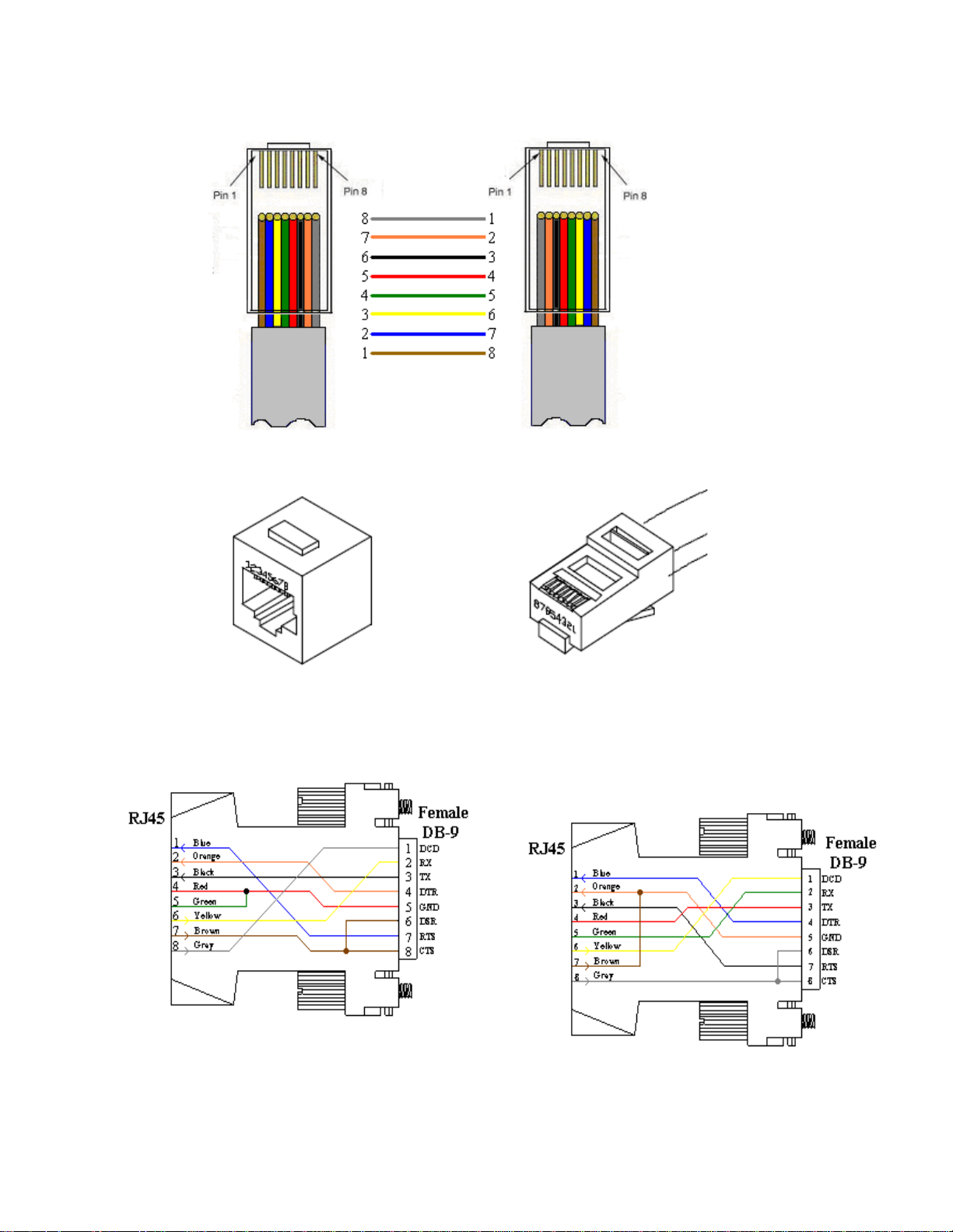
RJ08X007 Standard Rollover Cable RJ45 to RJ45
Figure 2: RJ08X007 Pin Out
Figure 3: RJ45 Connector & Plug
Adapters
Figure 4: 9FRJ45PC Cisco Adapter Pin Out
Figure 5: 9FRJ45PC-1 Adaptor Pin Out
(Use with RJ08X007 Cable
And B/C switch in “C”) (Use with RJ08X007 Cable
And B/C switch in “B”)
Page8
Page 9

ATS11 Front, ATS22 similar Front
ATS11/ATS22 Rear
ATS12 Rear on Top, Front on Bottom
ATS23 similar Rear but UL489 Breakers on Front panel
ATS11 and 12 same dimensions
Rear Switch & Indicators:
EIA232 INTERFACE B/C = Set switch to ‘B’ for normal operations. ‘C’ changes the pin out to allow
for Cisco’s PC cable to operate in most cases but not all.
Indicators:
ALM = Red LED Over-current alarm or an abnormally input voltage
PWR = Green LED power is connected to the unit through either source 1 or 2
Source 1 = Green LED lit indicates unit is using Source 1 as the Input power
Source 2 = Green LED lit indicates unit is using Source 2 as the Input power
Only one of the source LEDs will be lighted at a time, the source supplying power to the outlet(s).
Front Switch & Indicators:
None
Page9
Page 10

QUICKSTART:ATS
For those Administrators who have requested the bare minimum for this type of equipment, follow these
steps exactly. If this is a new unit shipped directly from Baytech, follow the steps. If this is a previously
owned unit, perform a factory reset to clear out any users and passwords still in the unit.
Main Control:
1. Connect the 9FRJ45PC-4 or 9FRJ45PC-1 adapter to your PC.
2. Connect the supplied rollover flat cable RJ08X007 to the adapter and to the EIA232 serial port on the
ATS.
3. Use terminal emulation software to access the unit, (i.e. Microsoft Hyper-terminal). Set the PC serial
port configuration to the following: 9600 bps, 8 data bits, 1stop bit and no parity. If your device has a
B/C switch near the EIA232 port, set it to “B”. (If you are using Cisco cable/adapter set this to C.)
4. If you get only a blinking cursor Press „Enter‟. If still only a blinking cursor, Type 5 semi-colons (;),
there is a one second delay before the menu is displayed.
5. You should get a Status menu similar to the one seen below.
ATS Series
(C) 2010 Baytech
F1.00
Option(s) Installed:
True RMS Voltage
True RMS Current
Internal Temperature
Unit ID: ATS Series
Primary Source 1
Source 2: 121.2 Volts
-----------------------------------------------------------------------------| Power | True RMS | Peak RMS | True RMS | Average | Volt- |
| Source | Current | Current | Voltage | Power | Amps |
-----------------------------------------------------------------------------| Source 1 | 0.1 Amps | 0.2 Amps | 121.7 Volts | 0 Watts | 21 VA |
------------------------------------------------------------------------------
Internal Temperature: 24.0 C
The number of outlets
listed depends on the
number of outlets
installed on the unit.
1)...Outlet 1 2)...Outlet 2
3)...Outlet 3 4)...Outlet 4
5)...Outlet 5 6)...Outlet 6
7)...Outlet 7 8)...Outlet 8
9)...Outlet 9 10)...Outlet 10
11)...Outlet 11 12)...Outlet 12
Type "Help" for a list of commands
ATS>
Page10
Page 11

DetailOperationsandConfigurations
The Status Menu will display after the user logs in (if a login is required). This menu lists the firmware
version, installed options, primary source, secondary source voltage, primary source current, voltage, and
power, and the internal temperature of the ATS unit.
ATS Series
(C) 2010 BayTech
F1.00
Option(s) Installed:
True RMS Current
Internal Temperature
True RMS Voltage
Enter user name:
Enter Password:
ATS Series
(C)2010 Baytech
F1.00
Option(s) Installed:
True RMS Current
Internal Temperature
True RMS Voltage
Primary Source 1
Source 2: 121.2 Volts
-----------------------------------------------------------------------------| Power | True RMS | Peak RMS | True RMS | Average | Volt- |
| Source | Current | Current | Voltage | Power | Amps |
-----------------------------------------------------------------------------| Source 1 | 0.1 Amps | 0.2 Amps | 121.7 Volts | 0 Watts | 21 VA |
------------------------------------------------------------------------------
Internal Temperature: 24.0 C
1)...Outlet 1 2)...Outlet 2
3)...Outlet 3 4)...Outlet 4
5)...Outlet 5 6)...Outlet 6
7)...Outlet 7 8)...Outlet 8
9)...Outlet 9 10)...Outlet 10
11)...Outlet 11 12)...Outlet 12
Type "Help" for a list of commands
ATS>
If there are users installed on the unit a login
will be required. This may have a password or
not. It is recommended that at least two users be
entered. The first user will be the Administrator
and will be able to manipulate the unit. This
user should be password protected. The second
user can be labeled “Guest” and need not be
protected. Both should be given access to the
outlet(s)
NOTE: Int. Temp = unit internal temperature reads in Fahrenheit or Celsius.
Type “help” at the prompt to display a list of commands to change the outlet state, outlet
configuration, and internal sensor measurements.
11
Page
Page 12

12>
HELPOPTIONS
Menu 1: Help
ATS> help
Status <cr> --ATS-11 Status
Config <cr> --Enter configuration mode
Current <cr> --Display True RMS Current
Voltage <cr> --Display True RMS Voltage
Clear <cr> --Reset the maximum detected current
Temp <cr> --Read current temperature
Logout <cr> --Logoff
Logoff <cr> --Logoff
Exit <cr> --Logoff
Password <cr> --Changes the current user password
Whoami <cr> --Displays the current user name
Unitid <cr> --Displays the unit ID
Type Help for list of commands
ATS>
Configuration Menu
To select the configuration menu, type ‘Config” at the prompt. Left screen shot older units, Right screen shot
2010 firmware
ATS11>config
Unit ID: ATS11
1)...Manage Users
2)...Enable/Disable Status Menu
3)...Change Unit ID
4)...Change Alarm Threshold
X)...Exit
Enter Request:
ATS11/
1)...Manage Users
2)...Change Outlet Name
3)...Enable/Disable Status Menu
4)...Change Unit ID
5)...Change Alarm Threshold
6)...Change ATS Switching Voltage Points
7)...Change ATS Switch Back mode/time
8)...Change ATS Delay Switch to secondary
X)...Exit
config
Manage User
Select 1), from the configure menu to allow the
admin user to add and delete users, change
passwords, and change the outlet list. The following
menu appears if the unit has been reset or initial
setup:
----------------------
| User | |
----------------------
----------------------
A)...Add User
D)...Delete User
R)...Rename User
Enter user number to assign Outlets, A, D or R.
Enter Request:
Add a User
NOTE: If the “Add user” option is NOT
present than the maximum number of users
have been assigned. You will get a message
saying „No more users can be added’.
NOTE: the first assigned user will be the
“admin user” for the outlet. Older units
will not display the “delete” option until a
user is added.
12
Page
Page 13

Select A), to add a user. The unit will
prompt for a user name.
Type the user name and press ‘Enter’.
NOTE: User name is case sensitive. The unit
will display the User Menu with the added user
name. Even thou the unit may have more than
one outlet, internally; the unit sees only one
output.
----------------------
| User | |
| | 1 |
----------------------
1)...Dave | N |
----------------------
A)...Add User
D)...Delete User
R)...Rename User
Enter user number to assign Outlets, A, D or R.
Delete a User
Select D), to delete a user. The unit will prompt for a user name.
Type the number of the user to be deleted, followed by <cr>. The ATS will display the User Menu minus
the deleted user.
NOTE: If you delete the user in the first position, the ATS will display the following:
Enter number for user to delete:
You are deleting the current admin user. The next user will become
the admin user, do you want to continue. (Y/N)?
IMPORTANT: The unit must have had a power cycle or unit reset command performed
recently prior to deleting the user in the first position. This action will prevent the unit
from having No Admin user assigned even though the first position user was deleted
and there is a second user assigned. If the No Admin condition occurs, you must reset
the unit to factory default.
Rename a User
Select R), to change the name of a user. The unit prompts for the user
number.
Type the number of the user to be renamed, press ‘Enter’. The unit will
prompt for the new name. Once accepted the unit displays the User menu
with the new name.
Enter user number to rename:
Enter user name:
13
Page
Page 14

Assigned Outlets
The Assigned Outlet Menu displays the outlets a user can access.
Select a user number from the Managed User Menu, the unit will
display the Assign Outlet Menu
Select 1), to assign outlet to a user. The unit will prompt for outlet
number
Select 2), to remove individual outlet from a user. The unit will prompt
for the outlet number.
Select 3), to add all outlets to user access. The unit will
display ‘Y’ for all outlets.
Select 4), to remove all outlets from a user
. The unit will display ‘Y’ for all outlets.
Change Outlet Name
Select 2), from the Configure Menu allows the ‘admin’ user to change
the names of the outlets. Select this option and the unit displays all of the
outlet names. Default name is Outlet 1. . . Outlet #, #=number of
outlets on unit.
Enable/Disable Status Menu
Select 3), from the Configure Menu allows the ‘admin’ user to enable
or disable the Status menu. The unit will display either option, depending
on the current Status menu state, to be changed:
If this feature is disabled, only the prompt appears.
Default setting is Enabled.
----------------------
| User | |
| | 1|
----------------------
| Dave | N|
----------------------
1)...Add Outlet(s)
2)...Remove Outlet(s)
3)...Add All Outlets
4)...Remove All Outlets
Enter Request:
Enter Outlet number(s):
Enter Outlet number(s):
----------------------
| User | |
| | 1|
----------------------
| Dave | Y|
----------------------
1)...Add Outlet(s)
2)...Remove Outlet(s)
3)...Add All Outlets
4)...Remove All Outlets
Enter Request: 3
Enter Request: 2
1)...Outlet 1
Enter Request: 1
Current Outlet: Outlet 1
Modify (Y/N)? y
Enter : Cisco Server
1)...Cisco Server
Enter Request:
Enable Status Menu(Y/N)?
Disable Status Menu (Y/N)?
Page14
Page 15

Change Unit ID
Select 4), from the Configure Menu allows the ‘admin’ user to
change the unit ID. Default is Blank. The unit displays the following:
Enter Request: 4
Current Unit ID: ATS12
Modify (Y/N)? y
Enter New Unit ID:ATS12 East
Unit ID: ATS12 East
Change Alarm Threshold
Select 5), from the Configure Menu allows the ‘admin’
user to set the over-current level for the internal alarm to
sound.
Default: 1 circuit breaker: 12.8 Amps
2 circuit breaker: Current =12.9 and Phase 2=12.8
Change ATS Voltage Switching Points
Select 6), from the configure menu to
allow the user to set the brownout voltage
switching points. The processor uses a 6-
cycle window to determine if the voltage
is greater than zero, but less than the
trip threshold. This should only be set
after the ATSSET command has been
performed. This value can be tweaked
according to loading. It is recommended
that the default values be maintained.
Enter Request: 6
Primary to Secondary trip voltage value : 160.9 Volts
Modify (Y/N)? y
Enter:
Secondary to Primary return voltage value : 173.1 Volts
Modify (Y/N)? y
Enter:
Enter Request: 5
Current buzzer alarm value : 12.6 Amps
Modify (Y/N)? y
Enter: 12.0
Change ATS Switch Back Mode/Time
Select 7), from the configure menu to allow the user to set the switch back mode and time. Default
is Enabled and the delay time is 0 seconds. This allows the unit to switch from primary to
secondary and back immediately upon reaching selected criteria, without operator intervention. If the
mode is disabled then the unit will switch from primary to secondary, but it will not switch back
without user intervention. If the mode is enabled and a time is set in, unit will switch back (8) seconds
plus nnnnn number of seconds after the selected criteria is met.
Enter Request: 7
Disable switch back to primary (Y/N)? n
Current delay switch back to primary source time is(0= minimum): 300 Seconds
Change delay switch back time (Y/N)? y
Enter seconds (0-65535):
Page15
Page 16

Change ATS Delay Switch to Secondary
Select 8), from the configure menu to allow the user to set the delay time the unit switches to the
Secondary Input once the Primary input drops below the Loss of Power Threshold. Default is
Enabled, and Default time is 60-seconds. This time can be adjusted from 1-255 seconds.
If this feature is already enabled, you get the question below. Type ‘Y’ and press Enter to disable the
feature and you will be sent back to the ‘config’ menu. Type ‘N’ and press Enter. The unit will
display the current switch time and ask if you want to change the time. Type ‘N’ and press Enter and
you will be sent back to the ‘config’ menu. Type ‘Y’ and press Enter. You will be asked to enter a
time of (1-255) seconds.
Enter Request: 8
Disable delay switch to secondary (Y/N)? Y
Enter Request:
Type ‘N’ and press Enter. The unit will display the current switch time and ask if you want to change
the time. Type ‘N’ and press Enter and you will be sent back to the ‘config’ menu. Type ‘Y’ and press
Enter. You will be asked to enter a time of (1-255) seconds.
Enter Request: 8
Disable delay switch to secondary (Y/N)? N
Current delay switch to secondary source time is: 3 Seconds
Change delay switch to secondary time (Y/N)? Y
Enter seconds (1-255):
If this feature is already Enabled, you get the question below. Type ‘N’ and press Enter to disable the
feature and you will be sent back to the ‘config’ menu. Type ‘Y’ and press Enter. The unit will
display the current switch time and ask if you want to change the time. Type ‘N’ and press Enter and
you will be sent back to the ‘config’ menu. Type ‘Y’ and press Enter. You will be asked to enter a
time of (1-255) seconds.
Enter Request: 8
Enable delay switch to secondary (Y/N)? y
Current delay switch to secondary source time is: 60 Seconds
Change delay switch to secondary time (Y/N)? Y
Enter seconds (1-255): 30
Page16
Page 17

Display Current Electrical Characteristics:
Type Current at the prompt to show the unit’s True
RMS Current and Peak RMS Current and the unit will
display the following:
Type Clear at the prompt to reset the Peak RMS Current,
the ATS will redisplay the status menu with the new
maximum detected current.
Type Voltage at the prompt to display the unit’s True
RMS Voltage and the unit will display the following:
Type Power at the prompt to show the unit’s Average
Power and the unit displays the following:
Type Temp at the prompt to show the unit’s current
temperature and the unit displays the following:
Int. Temp: 95.9 F Ext. 1: 72.1 F : 31.5% RH ; Ext. 2: 70.9 F
------------------------------------------
| Circuit | True RMS | Peak RMS |
| Group | Current | Current |
------------------------------------------
| Circuit C1 | 0.0 Amps | 0.7 Amps |
| Circuit C2 | 0.0 Amps | 0.0 Amps |
| Circuit C3 | 0.1 Amps | 0.5 Amps |
| Circuit C4 | 0.0 Amps | 0.9 Amps |
| Circuit C5 | 1.2 Amps | 1.8 Amps |
| Circuit C6 | 0.9 Amps | 1.4 Amps |
------------------------------------------
--------------------------------
| Circuit | True RMS |
| Group | Voltage |
--------------------------------
| Circuit C1 | 201.9 Volts |
| Circuit C2 | 204.3 Volts |
| Circuit C3 | 202.4 Volts |
| Circuit C4 | 202.1 Volts |
| Circuit C5 | 204.5 Volts |
| Circuit C6 | 205.8 Volts |
Total kW-h: 0
----------------------------------------
| Circuit | Average | Volt- |
| Group | Power | Amps |
----------------------------------------
| Circuit M1 | 0 Watts | 4 VA |
| Circuit M2 | 0 Watts | 4 VA |
| Circuit M3 | 0 Watts | 4 VA |
| Circuit M4 | 0 Watts | 4 VA |
| Circuit M5 | 0 Watts | 4 VA |
| Circuit M6 | 0 Watts | 4 VA |
Note: Units with probes connected to external sensor ports will be displayed as Ext 1 and/or Ext 2.
Logging Out
Type Logout, Logoff, or Exit at the prompt to logoff from the unit. This will close the Outlet Control
session. Press “Enter” to open the Outlet Controller session. A login prompt may appear if a user has
been assign to an outlet. Newer firmware may go to the network menu.
Current User Password:
Type Password at the prompt to change the current user’s password
and the unit will display the following:
If the current user already has a password the unit will display the
following:
NOTE: If you do not have the user’s current password, delete the user. Reinstall user. Select option
to change password and the unit will respond by asking for a new password.
Enter new Password:
Re-Enter new Password:
Enter old Password:
Enter new Password:
Re-Enter new Password:
17
Page
Page 18

Identify Current User
Type Whoami at the prompt to determine the current user, the unit will display the
following:
To change the user, logout of the unit and log back in using the new user name.
Unit Identification
Type Unitid at the prompt to determine the Unit ID, the unit will display the following:
To change the unit ID, Go to the Outlet Configuration menu and select “Change Unit
ID’ option. The maximum field length is 32 or 16 for older unit.
Setting Source Input Primary
Type source ‘n’, (n= 1 or 2) at the ATS> prompt. This will change the input to the
source selected and make it the primary input.
SETUPOPTIONS
ATSSET
Type ATSSET at the prompt, sets the pre-defined switch over points for power loss
and brownout. The preset values are listed below:
Default Set Points
Loss Of Primary Source Power
(LOSSPSP)
1 - 2 2 - 1 1 - 2 2 - 1
Brownout
(Config option 6)
100V 66.6V 91.7V 77.3V 83.2V
110V 73.2V 100.9V 85.1V 91.5V
120V 79.9V 110.1V 92.8V 99.8V
200V 133.2V 183.4V 154.7V 166.4V
208V 138.2V 190.8V 160.9V 173.1V
220V 146.5V 201.8V 170.2V 183.0V
230V 153.1V 210.9V 177.9V 191.4V
240V 159.8V 220.1V 185.6V 199.7V
Frequency Set
The menu displays the current operating frequency and then asks
the operator to choose the frequency. If no change is required
press “Enter”, otherwise select the appropriate number. Type
“X” to exit the ATSSET routine.
ATS>atsset
Current operating frequency is: 60 Hz
Enter operating frequency
1)...60 Hertz
2)...50 Hertz
X)...Exit
Enter(1-2,X):
Current User: root
Unit ID: ATS18
Page18
Page 19

Voltage Set
The menu displays the current operating voltage and then asks
the operator to choose the new operating voltage. If no change is
required press “Enter”, otherwise select the appropriate number.
Type “X” to exit the ATSSET routine.
LOSSPSP
(Loss of Primary Source Power)
Type “LOSSPSP” at the prompt to check or
to change the value of the loss of power set
point. This set point establishes when the unit
will switch from primary to secondary power
and back. The processor uses ¼ cycle
window to determine if the power is at
Zero.
These values are preset when an ATSSET
routine is run. Changing the values is allowed
but could cause the unit to operate in ways
not previously determined. It is recommended
that the default values be used.
ATS>losspsp
Primary to secondary trip primary voltage value : 138.5 Volts
Modify (Y/N)? y
Enter:
Secondary to primary return voltage value : 190.8 Volts
Modify (Y/N)? y
Enter:
Type Help for a list of commands
RESETPROCEDURE
On the front panel is a small hole next to the LED. Perform the
following steps:
Insert paper-clip or similar object into the hole
Press the micro-switch and hold until the last step.
Remove power from the unit and wait 15 seconds.
Restore power to the unit and wait 15 seconds.
Remove paperclip. Unit is at factory default settings.
Current operating voltage is: 208.0 Volts
Enter operating voltage
1)...100 Volts
2)...110 Volts
3)...120 Volts
4)...200 Volts
5)...208 Volts
6)...220 Volts
7)...230 Volts
8)...240 Volts
X)...Exit
Enter(1-8,X):
Page19
Page 20

BAYTECHPRODUCT(US)WARRANTY
Bay Technical Associates (BayTech) warrants that its products will be free from defects in materials and
workmanship under normal use for a period of two years from date of purchase (or date of shipment) from
BayTech if proof of purchase is not provided.
During this warranty period, BayTech shall, at its discretion, either repair or exchange any defective
product at no charge for labor and materials, or refund the amount paid for the product, less shipping and
handling charges. Any replacement and/or repaired products are warranted for the remainder of the original
warranty.
The customer is responsible for properly packaging the product and for shipping costs for returns. The
customer is liable for loss or damage to the product during shipping, as well as any other fees or charges
associated with transporting the product back to BayTech. BayTech will pay return costs for delivery
within the Continental United States.
All repair and return shipments must be approved by BayTech and must be accompanied by an RA (return
authorization) number. Please refer to our Repair and Return Policy below.
For the initial 30 days from the original date of shipment, any unopened product may be returned to
BayTech, accompanied by an RA number. Full purchase price will be refunded, provided that the product
is in excellent condition. A product may not be returned after 30 days from the original date of shipment
unless approved by BayTech management.
Replacements for defective products may be cross-shipped to the customer at no cost if requested within
30 days of date of purchase. At BayTech’s discretion, this period may be extended to 90 days.
For additional information or more specific warranty issues, contact BayTech’s Technical Support
Department at (800) 523-2702 or (228) 563-7334.
Exceptions
This warranty does not cover misuse or minor imperfections that fall within design specifications or that
do not materially alter functionality. BayTech does not warrant and is not responsible for damages
incurred in shipping and handling or caused by disasters (such as fire, flood, wind, earthquake, lightning,
power surges or water).
The warranty will be voided regarding products that have been neglected, altered, abused, misused, or
used for purposes other than those for which it was designed.
Under no circumstances shall BayTech be liable for any special, incidental, or consequential damages
based upon breach of warranty, breach of contract, negligence, strict liability, or any other legal theory.
Such damages include (but are not limited to) loss of profits, loss of the product or associated equipment,
cost of capital, cost of substitute or replacement equipment, facilities or services, down time, purchaser’s
time, the claims of third parties, including customers, and injury to property.
BayTech Extended Warranty
Extended warranties and overnight replacements are available for purchase, but only at the time of
product purchase. The extended warranty cost will not exceed 7% per year of the product list price
unless otherwise stated in the customer contract or approved by BayTech management. Contact
BayTech for further details on this.
Page20
Page 21

Technical Support
BayTech offers Tech Support for the lifetime of the product. A staff of Applications Engineers is on duty
to assist with installation, set up or operation issues. Support is available from 8:00 a.m. to 5 p.m. (CST or
CDT), Monday through Friday at the phone numbers or website provided below.
Please have the following information available to help the Applications Engineers answer questions
efficiently:
Bay Technical Associates, Inc.
5239 A Avenue
Long Beach Industrial Park
Long Beach, MS 39560
Telephone: 800-523-2702 or 228.563.7334
FAX: 228.563.7335
Email: support@baytech.net
Website: www.baytech.net
BayTech model type
Unit serial number
Firmware version (if accessible)
A list of devices connected to the BayTech unit
A general description of the application being used and the intended outcome
Information about cables and adapters being used (type, length, place of purchase)
The name of the software emulation program being used
Printout of the configuration status (if possible)
Repair Policy
(Return policy refers to BayTech products purchased and returned for credit or repair.)
A Return Authorization (RA) number must be obtained in all cases before returning the BayTech product.
Have the serial number and reason for the return or description of the problem handy. Customers in the
Continental U.S. can call 1-800-523-2702 or international customers can call 228.563.7334 to obtain an
RA number.
If a product is being returned for credit (based on BayTech approval), the credit will not include shipping
and handling charges. Determination of credit amount will be made after BayTech receives the product.
Returns on BayTech products older than 3 months are subject to a 15% re-stocking fee of the list price of
the product and will be evaluated on a case-by-case basis. BayTech does not allow returns on products out
of warranty or for any type of custom product.
Before dismantling equipment or returning the unit for any reason, always contact BayTech. Attempting
to repair a product without BayTech authorization may result in voiding the warranty.
Follow the instructions below for repackaging and shipping. NOTE: Power should be disconnected from
the power source before servicing or dismantling.
Page21
Page 22

Return Authorization Process
1. Contact BayTech to get a Return Authorization (RA) Number. IMPORTANT: BayTech will not
accept any returns without an RA number.
2. Package the unit carefully in its original packaging or similar packaging. The warranty does not
cover damage sustained during shipment. Enclose a letter with name, address, RA number,
daytime phone number and description of the problem.
3. Surround your unit with a minimum of two inches of insulation.
4. Be sure to seal the box securely with strapping or packing tape. We do not recommend masking
tape or cellophane tape.
5. Mark the RA number clearly on the outside of the package.
6. Ship the unit by insured, prepaid carrier to the following address:
Bay Technical Associates
5239 A Avenue
Long Beach Industrial Park
Long Beach, MS 39560
RA #: 140-xxxxx
Page22
Page 23

TROUBLESHOOTING
Problem: Solution: Reference:
Unit Switches Continuously Verify the voltage and frequency is set
for the input voltage via ATSSET
command
Unit has long beep and long
pauses continuously, Part 1
Unit has long beep and long
pauses continuously, Part 2
Unit beeps and Alarm LED
lights continuously
Not able to communicate
with EIA232 port
The beeping signifies NO VOLTAGE
from one input, Connect both inputs to
power source.
Unit is operating on Secondary source.
Enable the Secondary Switch-Back,
option 7, and change the switch-back
time if necessary
The alarm is over-current alarm. Check
unit current. If close to 12 amps, either
disconnect some devices or adjust the
‘Over Current Alarm Threshold’
Verify using RJ08X007 cable, 9-pin
adaptor 9FRJ45PC-1, B/C switch is set to
‘B’.
Page 17
This is normal operation. No means
of silencing beeping
Page 15, Change ATS Switch Back
Mode/Time
Page 15, Change Alarm Threshold
Page 10, ATS Quick Start
When the ALARM Sounds
A new feature, that was requested, has been added to the unit concerning when the alarm lights and buzzer
sounds. There is NO ‘Silence the Alarm’
1. If the Alarm LED is light solid and the buzzer sounds without pauses, you have an Over-Current
condition.
a. -Solution: clear the over-current condition.
2. If the Alarm LED is light intermittent and the buzzer sound intermittent on a cyclic rate of long beep,
long pause than beeps again, one of the input voltages has either a “Loss of Power”, a Brown-Out”
condition, or the unit is operating on the secondary input.
a. -“Loss of Power”, restore the power to proper voltage level. The unit will switch to the primary
after 8-seconds plus any time delay set in the switch-back feature of the ‘Config/Option (7),
Change ATS Switch Back Mode/Time’, Default is (0) seconds.
b. -“Brown-Out”, verify the input voltage is at the proper voltage level.
c. -“Unit operating on Secondary Input Voltage”, If ‘Config/Option (7) Change ATS Switch Back
Mode/Time’ is Disabled the unit will not switch back to the Primary; the alarm will light and the
buzzer will sound continuously. If the Switch Back Mode is enabled, the unit will switch (8)
seconds plus any time delay set. The Default time delay is set to (0) seconds.
Page23
Page 24

BracketInstallation
HORIZONTAL Mounts:
Each horizontal, Baytech unit is shipped with a set of horizontal brackets, and four screws packaged
in a bubble-wrap bag.
1U Bracket, part number: M140R115
Attach brackets to the each of the unit’s side panel with two screws. Verify both brackets are facing the
same direction on the unit, once attached.
Bracket 1: 1U - M140R115
2U Bracket, part number: M140R114
Attach brackets to the each of the unit’s side panel with two screws: Verify both brackets are facing the
same direction on the unit, once attached.
Bracket 2: 2U - M140R114
Attach brackets and unit to rack with four screws as shown below.
Bracket 3: Horizontal to Rack
Page24
 Loading...