

Baytec RTA04W User Manual

RTA04W
ADSL2+ 11b/g HOME GATEWAY
User Manual

CONTENT TABLE
1. I
NTRODUCTION
................................................................................................................. 4
2. A
PPLICATION
.................................................................................................................... 4
3. T
ECHNICAL SPECIFICATIONS AND FEATURES
.............................................................................. 5
4. P
ACKING LIST
................................................................................................................... 8
5. S
AFETY PRECAUTIONS
......................................................................................................... 8
6. LED
S AND INTERFACES
........................................................................................................ 9
7. H
ARDWARE INSTALLATION
................................................................................................. 10
8. A
CCESS THE ROUTER
........................................................................................................ 11
9. S
TATUS
......................................................................................................................... 12
10. LAN C
ONFIGURATION
...................................................................................................... 13
11. W
IRELESS CONFIGURATION
................................................................................................ 15
11.1. B
ASIC SETTINGS
.................................................................................................................... 15
11.2. A
DVANCED SETTINGS
............................................................................................................. 16
11.3. S
ECURITY
............................................................................................................................. 18
11.4. A
CCESS CONTROL
.................................................................................................................. 20
11.5. WPS ................................................................................................................................... 22
12. WAN C
ONFIGURATION
..................................................................................................... 24
12.1. C
HANNEL CONFIGURATION
..................................................................................................... 24
12.2. ATM S
ETTING
...................................................................................................................... 25
12.3. ADSL S
ETTING
...................................................................................................................... 27
13. S
ERVICES
....................................................................................................................... 28
13.1. DHCP C
ONFIG
...................................................................................................................... 28
13.1.1. DHCP Mode .............................................................................................................. 28
13.2. DNS ................................................................................................................................... 31
13.2.1. DNS Server................................................................................................................ 32
13.2.2. Dynamic DNS ............................................................................................................ 33
13.3. A
CCESS CONTROL
.................................................................................................................. 34
13.3.1. ACL ............................................................................................................................ 34
13.3.2. IP/Port Filtering ........................................................................................................ 36
13.4. NAT/PAT ............................................................................................................................ 37
13.4.1. Virtual Server ............................................................................................................ 38
13.4.2. NAT IP Pool ............................................................................................................... 38
13.4.3. NAT Forwarding ....................................................................................................... 39
13.4.4. NAT ALG and pass through....................................................................................... 39
13.5. P
RIORITY QUEUE
................................................................................................................... 40
13.6. Q
OS CLASSIFICATION
............................................................................................................. 40
13.7. T
RAFFIC SHAPING
.................................................................................................................. 41
13.8. MAC F
ILTERING
.................................................................................................................... 42

13.9. DMZ................................................................................................................................... 43
13.10. URL BLOCK ........................................................................................................................ 44
13.11. DOS S
ETTING
....................................................................................................................... 45
13.12. IGMP P
ROXY
....................................................................................................................... 45
13.13. RIP ..................................................................................................................................... 47
14. A
DVANCED CONFIGURATION
.............................................................................................. 48
14.1. B
RIDGING
............................................................................................................................ 48
14.2. L
OG SETTING
........................................................................................................................ 49
14.3. R
OUTING
............................................................................................................................. 50
14.4. UPNP C
ONFIGURATION
.......................................................................................................... 52
14.5. SNMP C
ONFIGURATION
........................................................................................................ 53
14.6. S
YSTEM TIME
....................................................................................................................... 54
14.7. O
THER ADVANCED CONFIGURATION
......................................................................................... 55
14.8. P
ORT MAPPING
.................................................................................................................... 56
15. D
IAGNOSTIC
................................................................................................................... 57
15.1. P
ING
................................................................................................................................... 57
15.2. T
RACEROUTE
........................................................................................................................ 58
15.3. ATM L
OOPBACK
................................................................................................................... 58
16. A
DMIN
.......................................................................................................................... 59
16.1. C
OMMIT / REBOOT
................................................................................................................ 59
16.2. B
ACKUP/RESTORE
................................................................................................................. 60
16.3. P
ASSWORD SETUP
................................................................................................................. 61
16.4. U
PGRADE FIRMWARE
............................................................................................................. 61
16.5. TR-069 C
ONFIG
. .................................................................................................................. 62
17. S
TATISTICS
..................................................................................................................... 63

1. Introduction
The RTA04W is a router with wireless local area network (WLAN) function. It is a high integrated
residential broadband access device, which provides one ADSL2+ RJ11 interface, four built-in
Ethernet interfaces, and one wireless access point. The RTA04W is fully compliant with ADSL/2/2+
standards. The Ethernet interface complies with IEEE802.3/802.3u standards, and the WLAN
interface complies with IEEE802.11b/g standards. This device provides high performance access to
Internet, downstream up to 24Mbps and upstream up to 1Mbps.
Computers on the LAN side can share the Internet access through the Ethernet interface or
wireless access point. These local computers can communicate and share resources and files with
each other when the RTA04W is connected to the Internet with DSL line.
• Support up to 8 permanent virtual circuits (PVCs)
• Provide one RJ11 interface and four built-in RJ45 interfaces
• IGMP Snooping and IGMP Proxy
• General IP: NAT, PAT, DHCP server, DHCP relay, and DNS relay
• Routing: Static routing, RIP V1 and V2
• Security: NAT, IP filtering, password authentication, and denial of service (DoS)
• Compatible with IEEE 802.11b and IEEE 802.11g
2. Application
This device can provide high access performance applications for individual users, SOHOs, and
small enterprises. Specific applications can be:
• Broadband Internet access sharing
• Higher data rate broadband sharing
• Audio, video streaming, and transfer
• PC file and application sharing
• Network and online gaming

3.
Technical Specifications and features
Product Specification of RTA04W
Model
RTA04W
Product Name
54M Wireless 802.11b/g ADSL2+ Router
Physical Specifications
User Interface
RJ45 4
RJ11 1
Reset button 1
Power Jack 1
On/Off Switch 1
WPS/WiFi button 1
Dimensions (W×D×H) 170 * 120 * 33 mm
Features
Protocol Feature
RFC 1483 Bridge
IEEE 802.1D transparent bridging
Bridge Filtering
RFC 1483 Router
RIP 1 & 2 supported
DHCP (RFC1541) Server, Relay
Network Address Translation (NAT)/ Network
Address Port
Translation (NAPT)
DNS relay
IGMP v1 and v2
ADSL Feature
Support ANSI T1.413 Issue2
Support ITU G.992.1 (G.dmt) Annex A
Support ITU G.992.2 (G.lite) Annex A
Support ITU G.992.3 ADSL2 (G.dmt.bis)
Annexs A, L, M

Support ITU G.992.4 ADSL2 (G.lite.bis)
Support ITU G.992.5 ADSL2 plus
Ethernet Feature
Fully compliant with IEEE802.3/802.3u autonegotiation function
Support 10 base-T and 100 base-TX
Support half duplex and full duplex
Support back pressure flow control for half
duplex, IEEE802.3x
flow control for full duplex
Support MDI/MDIX auto cross
Security
Support firewall function
Support revised passwords of two-level users
Support electronic signature (preventing
different types of versions from upgrading each
other)
Support denial of service (DoS ) which detects
and protects against a number of attacks (such
as SYN/FIN/RST Flood, Smurf, WinNuke, Echo
Scan, Xmas Tree Scan)
Management
Support Web and TFTP modes for local and
long-distance version upgrade
Support test estate of circuitry connect
(diagnostics)
Support settings in the Web interface
Support Telnet CLI command line
Support user setting the reset function:
hardware reset or Web interface mode
Support configuration files backup and
restoration
Support modifying IP address of the LAN
interface
Support system log
Support SNMP V1/V2C local and long-distance

control (MIB II
RFC1213/ADSL line MIB RFC 2662 ATM MIB
RFC 2515)
Support SNTP enactment
Support TR069
Wireless
Standards
IEEE 802.11g, 802.11b
Fre
quency range
2.400-2.4835GHz
(ISM frequency bands)
Wireless signal rates
802.11b compliant: 11, 5.5, 2, 1 Mbps
(DSSS/CCK);
802.11g compliant: 54, 48, 36, 24, 18, 12, 9, 6
Mbps (OFDM)
Wireless operating range
Transmission Distance: 300 meters outdoors,
100 meters indoors coverage area (varying
depending on the actual environment.)
Wireless security
64/128-bit WEP, AES, TKIP, WPA, WPA2,
802.1x
Antenna
Single external antenna
Power
Input/Output
Input power: 100-240 V DC, 50/60Hz
Output power: 12 V DC/800mA(min)
Environment
Operating Temperature 0℃~50℃
Storage Temperature
-20ºC~70ºC
Operating Humidity
5%~95%, non-condensing
Storage Humidity
5%~95%, non-condensing

4. Packing List
The content of the packaging is as follows:
• 1 x RTA04W
• 1 x power adapter
• 2 x Micro filter
• 1 x Double Micro filter
• 1 x telephone cables (RJ11)
• 1 x Ethernet cable (RJ45)
• 1 x QSG
• 1 x GVT service guide
5. Safety Precautions
Follow the following instructions to prevent the device from risks and damage caused by fire
or electric power:
• Use volume labels to mark the type of power.
• Use the power adapter packed within the device package.
• Pay attention to the power load of the outlet or prolonged lines. An overburden
power outlet or damaged lines and plugs may cause electric shock or fire accident. Check
the power cords regularly. If you find any damage, replace it at once.
• Proper space left for heat dissipation is necessary to avoid damage caused by overheating
to the device. The long and thin holes on the device are designed for heat dissipation to
ensure that the device works normally. Do not cover these heat dissipation holes.
• Do not put this device close to a place where a heat source exists or high temperature
occurs. Avoid the device from direct sunshine.
• Do not put this device close to a place where it is over damp or watery. Do not spill any
fluid on this device.
• Do not connect this device to any PCs or electronic products, unless our customer engineer
or your broadband provider instructs you to do this, because any wrong connection
may cause power or fire risk.
• Do not place this device on an unstable surface or support.
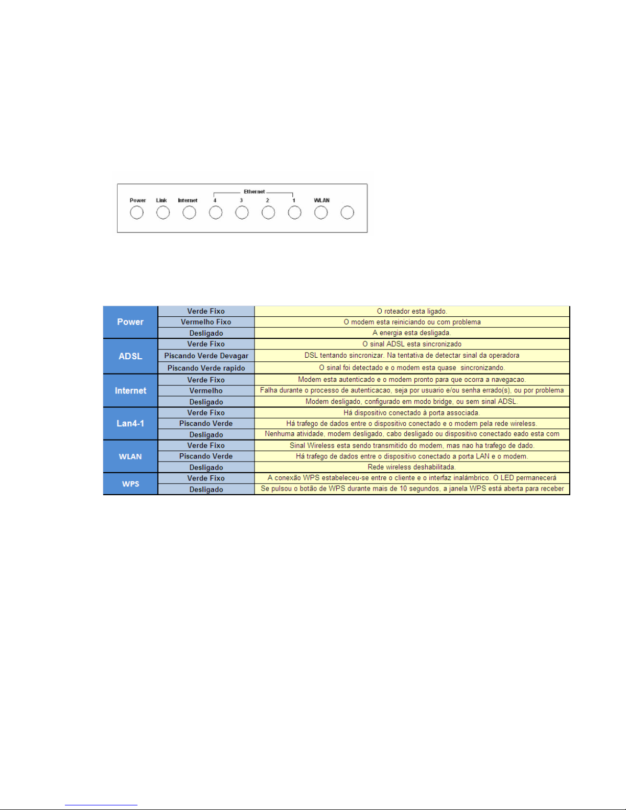
6. LEDs and Interfaces
Front Panel
The following table describes the LEDs of the device:
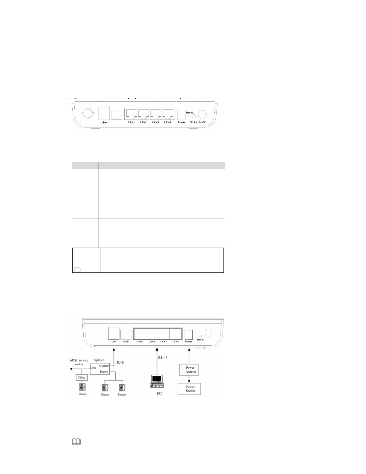
Rear Panel
The following table describes the interfaces of the device:
I
tems Description
RJ-11 interface, for connecting to the ADSL interface or a splitter
through
the telephone
cabl
e.
LAN1,
LAN2,
LAN3,
RJ-45 interface, for connecting to the Ethernet interface of PC
Or other Ethernet devices through the Ethernet cable.
Power
Power interface, for connecting to the power adapter.
Reset
Reset to the factory defaults. To reset to the factory defaults, keep
the device powered on and push a paper clip in to the hole for
over 3 seconds. Then release it, the configuration is reset to the
factory defaults.
WLAN/WPS
Button to enable and disable Wireless interface and establish WPS
connection
Power switch, power on or power off the device.
7. Hardware Installation
Following figure shows the connection of the router to the different elements of the network.
Connection diagram (Connecting a telephone set before the splitter)
Note:

The filter must be installed close to the telephone cable. See Figure2. Do not use the
splitter to replace the filter.
Installing a telephone directly before the splitter may lead to failure of connection between the
device and the central office, or failure of Internet access, or slow connection speed. If you really
need to add a telephone set before the splitter, you must add a micro filter before a telephone
set. Do not connect several telephones before the splitter or connect several telephones with
the micro filter.
8. Access the Router
The following is the detailed description of accessing the router for the first time.
Step 1 Open the Internet Explorer (IE) browser and enter http://192.168.1.1.
Step 2 In the Login page that is displayed, enter the username and password. The username
and password of the equipment are admin and gvt12345 respectively.
The following page will be shown after correct username and password enter.
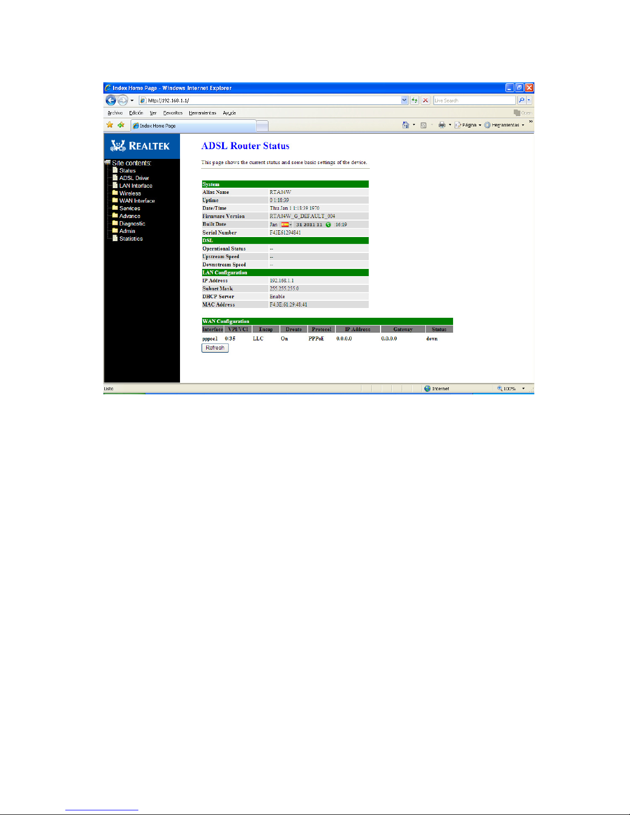
9. Status
Status page shows the current status and some basic settings of the router, such as uptime,
software version, upstream speed, downstream speed, and other information

10. LAN Configuration
This page shows current LAN configuration. You can configure IP address, network mask and
secondary IP address:
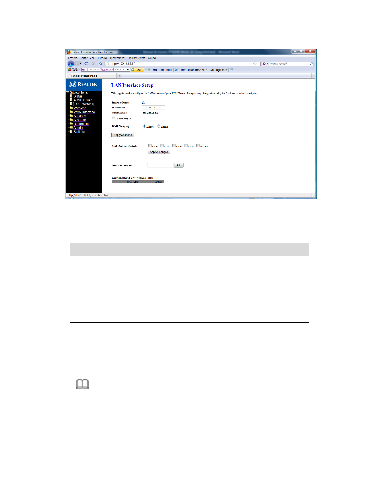
Fields in this screen are the following:
Field
Description
IP Address
IP address the LAN hosts can use to identify t
he LAN port of
its device.
Subnet Mask
LAN sub network mask.
Secondary
IP
Secondary IP (or emergency) and mask.
MAC Address Control
Access control based in MAC address at LAN level
.
If selected, one MAC included in the list will have access.
Apply Cha
nges Click here to keep settings temporarily.
Add
Enter MAC addresses and click Add
Note:
Secondary LAN IP and LAN IP must be in different network segments; otherwise
the page will report a configuration error message.
11. Wireless Configuration
There are five sub-menus for Wireless configuration: [Basic Settings], [Advance Settings], [Security],
[Access Control] and [WPS].
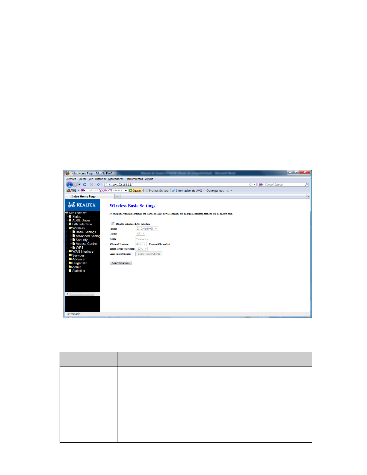
11.1.
Basic Settings
This page is used to configure the parameters for wireless LAN clients who may connect to your Access
Point. Please refer to the section – Basic settings for details.
Fields in this page:
Field
Description
Disable Wireless LAN
Interface
Check it to disable the wireless function for ADSL modem.
Band
Select the appropriate band from the list provided to
correspond with your
network setting.
Mode
Access Point
—
The gateway communicates with both clients and bridges.
SSID Enter a name for your wireless network here. SSID stands for Service Set
Identifier.
Channel Number
Drop
-
down menu that allows selection
of specific channel.
Radio Power
The maximum output power: 15mW, 30mW or 60mW.
Function buttons in this page:
Associated Clients
Click it will show the clients currently associated with the ADSL modem.
Apply Changes
Change the settings. New parameters will take effect after save into flash memory and reboot the
system
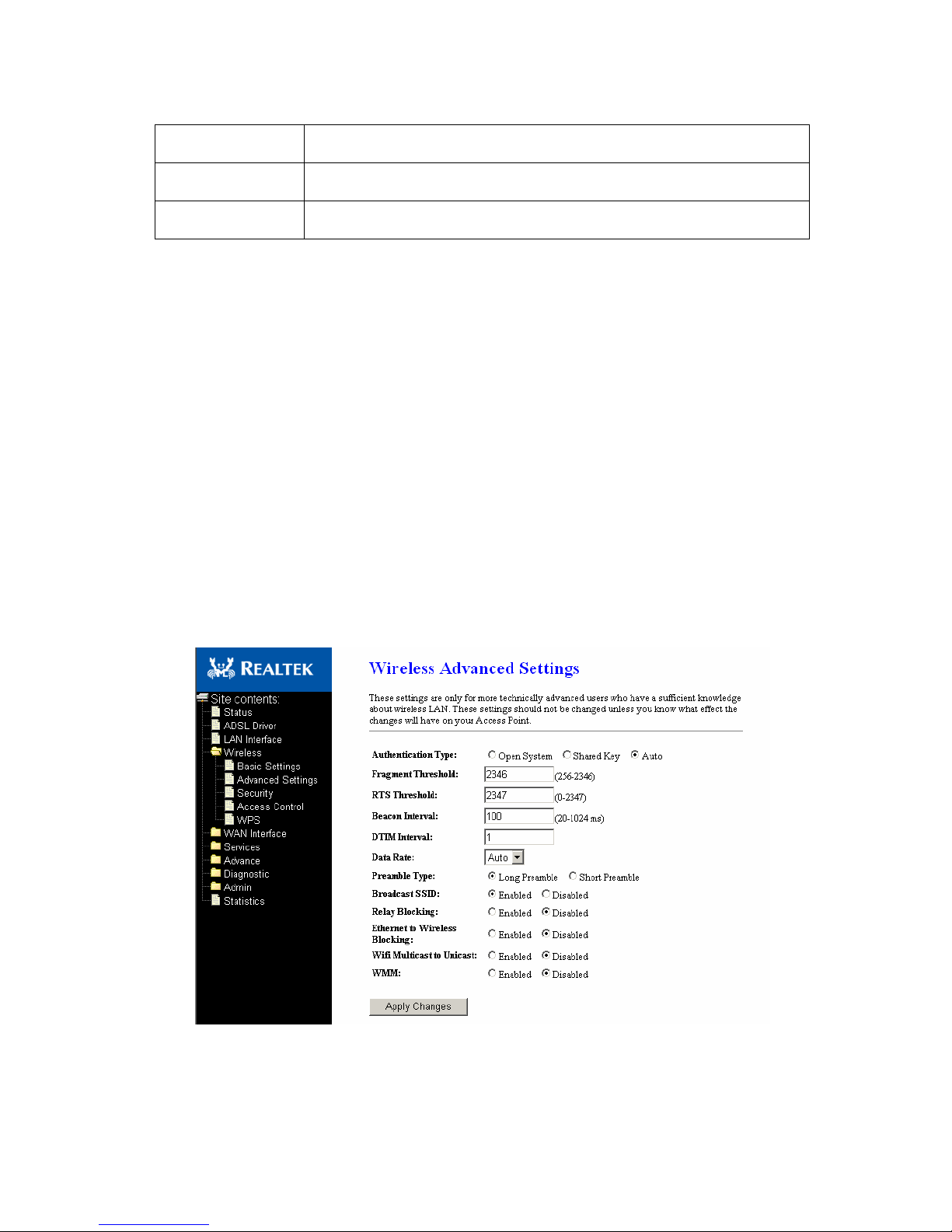
11.2.
Advanced Settings
This page allows advanced users who have sufficient knowledge of wireless LAN. These setting shall
not be changed unless you know exactly what will happen for the changes you made on your DSL
device. Please refer to the section – Advance settings for details.
Fields in this page:

Field
Description
Authentication Type
Open System:
Open System authentication is not required
to be successful while a client may decline to authenticate
with any particular other client.
Shared Key: Shared Key is only available if the WEP option
is implemented. Shared Key authentication supports
authentication of clients as either a member of those who
know a shared secret key or a member of those who do not.
IEEE 802.11 Shared Key authentication accomplishes this
without the need to transmit the secret key in clear.
Requiring the use of the WEP privacy mechanism.
Auto: Auto is the default authentication algorithm. It will
change its authentication type automatically to fulfill client’s
requirement.
Fragment Threshold
This value should remain at its default setting of 2346. It
specifies the maximum size for a packet before data is
fragmented into multiple packets. If you experience a high
packet error rate, you may slightly increases the “Fragment
Threshold” value within the value range of 256 to 2346.
Setting this value too low may result in poor network
performance. Only minor modifications of this value are
recommended.
RTS Thresho
ld This value should remain at its default setting of 2347. Should you
encounter inconsistent data flow, only minor modifications are
recommended. If a network packet is smaller than the preset “RTS
threshold” size, the RTS/CTS mechanism will not be enabled. The ADSL
modem (or AP) sends Request to Send (RTS) frames to a particular receiving
station and negotiates the sending of a data frame. After receiving an RTS,
the wireless station responds with a Clear to Send (CTS) frame to
acknowledge the right to begin transmission.
Beacon Interval
The Beacon Interval value indicates the frequency interval of the beacon.
Enter a value between 20 and 1024. A beacon is a packet broadcast by the
ADSL modem
(Or AP) to synchronize the wireless network. The default is 100.
Data Rate
The rate of data transmission should be set depending on the speed of your
wireless network. You should select from a range of transmission speeds, or
you can select Auto to have the ADSL modem (or AP) automatically use the
fastest possible data rate and enable the Auto-Fallback feature. AutoFallback will negotiate the best possible connection speed between the AP
and a wireless client. The default setting is Auto.

Preamble Type
The Preamble Type defines the length of the CRC (Cyclic Redundan
cy Check)
block for communication between the AP and mobile wireless stations.
Make sure to select the appropriate preamble type. Note that high network
traffic areas should use the short preamble type. CRC is a common
technique for detecting data transmission errors.
Broadcast SSID
If this option is enabled, the device will automatically transmit their network
name (SSID) into open air at regular interval. This feature is intended to
allow clients to dynamically discover and roam between WLANs; if this
option is disabled, the device will hide its SSID. When this is done, the
station cannot directly discover its WLAN and MUST be configure with the
SSID. Note that in a home Wi-Fi network, roaming is largely unnecessary
and the SSID broadcast feature serves n
o useful purpose. You should disable
this feature to improve the security of your WLAN.
Relay Blocking
When
Relay Blocking
is enabled, wireless clients will not be able to directly
access other wireless clients.
VMM support
WMM is a QoS solution with ind
ustry
-
wide support that offers strong
interoperability, meets the requirements of all market segments, and has
global reach. It is available now and will be interoperable with 802.11e. The
Wi-Fi Alliance has launched a WMM certification program that establishes a
solid foundation for the growth of the Wi-Fi multimedia market, and that
facilitates the development of interoperable devices and applications with
QoS capabilities. At the same time, WMM greatly improves the end-user
experience and enables a wider, more efficient use of Wi-Fi networks
everywhere.
Function buttons in this page:
Apply Changes
Click to commit changes.
11.3.
Security
This screen allows you to setup the wireless security. Turn on WEP or WPA by using encryption
keys could prevent any unauthorized access to your WLAN. Please refer to the section – Security
for details.
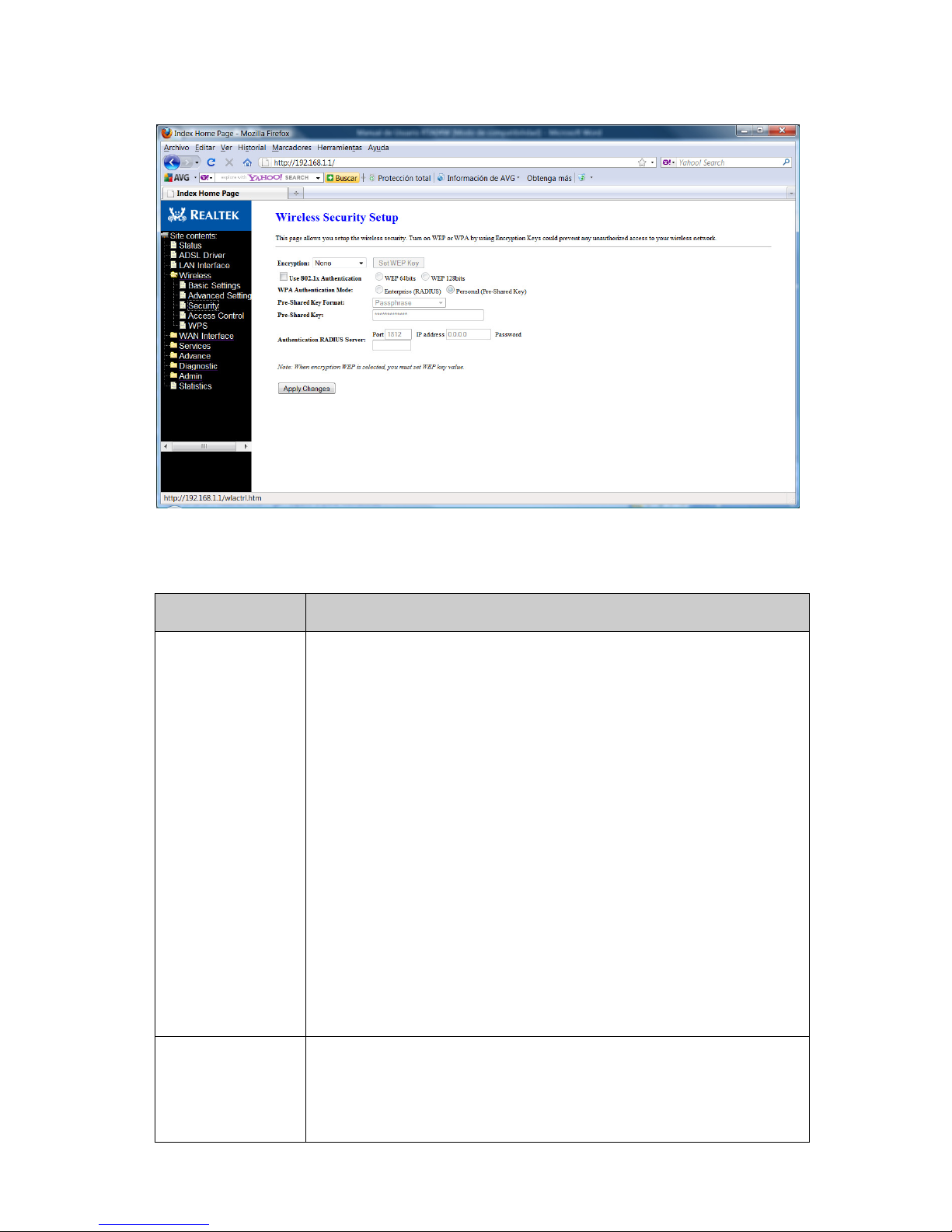
Fields in this page:
Field
Description
Encryption
There are 4 types of security to be selected. To secure your WLAN, it’s
strongly recommended to enable this feature.
WEP: Make sure that all wireless devices on your network are using the
same encryption level and key. Click Set WEP Key button to set the
encryption key.
WPA (TKIP): WPA uses Temporal Key Integrity Protocol (TKIP) for data
encryption. TKIP utilized a stronger encryption method and incorporates
Message Integrity Code (MIC) to provide protection against hackers.
WPA2 (AES): WPA2, also known as 802.11i, uses Advanced Encryption
Standard (AES) for data encryption. AES utilized a symmetric 128-bit block
data encryption.
WAP2 Mixed: The AP supports WPA (TKIP) and WPA2 (AES) for data
encryption.
The actual selection of the encryption methods will depend on the clients.
Use 802.1x
Authentication
Check it to enable 802.1x authentication. This option is selectable only
when the “Encryption” is choose to either None or WEP. If the “Encryption”
is WEP, you need to further select the WEP key length to be either WEP
64bits or WEP 128bits.

WPA Authentication
code
There are 2 types of authentication mode for WPA.
WPA-RADIUS: WPA RADIUS uses an external RADIUS server to perform user
authentication. To use WPA RADIUS, enter the IP address of the RADIUS
server, he RADIUS port (default is 1812) and the shared secret from the
RADIUS server. Please refer to “Authentication RADIUS Server” setting
below for RADIUS setting.
The WPA algorithm is selected between TKIP and AES, please refer to “WPA
cipher Suite” below.
Pre-Shared Key: Pre-Shared Key authentication is based on a shared secret
that is known only by the parties involved. To use WPA Pre-Shared Key,
select key format and enter a password in the “Pre-Shared Key Format” and
“Pre-Shared Key” setting respectively. Please refer to “Pre-Shared Key
Format” and “Pre-Shared Key” setting below.
Pre-Shared Key
Format
Passphrase
:
Select this
to enter the Pre
-
Shared Key secret as user
-
friendly
textual secret.
Hex (64 characters): Select this to enter the Pre-Shared Key secret as
hexadecimal secret.
Pre-Shared Key
Specify the shared secret used by this Pre
-
Shared Key. If the “Pre
-
Shared
Key Format” is specified as Passphrase
, then it indicates a passphrase of 8 to
63 bytes long; or if the “Pre-Shared Key Format” is specified as Passphrase,
then it indicates a 64-hexadecimal number.
Authentication
RADIUS Server
If the
WPA
-
RADIUS
is selected at
“WPA Authentication Mode”, the port
(default is
1812), IP address and password of external RADIUS server are specified
here.
Function buttons in this page:
Apply Changes
Click to commit changes.
11.4.
Access Control
This page allows administrator to have access control by enter MAC address of client stations. When
Enable this function, MAC address can be added into access control list and only those clients whose
wireless MAC address are in the access control list will be able to connect to your DSL device (or AP).
Please refer to the section – Access control for details.
 Loading...