

Baytec A3X Pro User Manual
F/W Version 2.1
1
A3X Pro Expert Flight Control System
User Manual
Version 2.1
Software has been improved to allow you to reverse the gyro direction for aileron 2 and elevator 2
independently now, which will give you more flexibility to setup your plane when using a dual aileron or
elevator system.
A new feature called “Brown-out Fast Recovery” is added to improve the reliability. When an
unforeseen power failure occurs such as a voltage drop or interruption from the external BEC during flight,
the controller will perform a fast startup process and resume working very quickly after a reboot. Self-test
and gyro calibration will be skipped in the fast start mode to avoid losing control of the aircraft. See P9
“Brown-out Fast Recovery” for more details.
The newest firmware files for A3X Pro Expert Ver.2.1 and some additional software can be downloaded from
our website HTTP://WWW.BAY-TEC.DE. The download package also contains a step-by-step
instruction document which can help you to complete your upgrade. To use A3X Pro E. Ver.2.1, the program
card should be updated to Ver.2.1 as well. If you haven't a program card, please download the config tool
corresponding to ver.2.1 for setting.
How to Upgrade to Ver.2.1?
HTTP://WWW.BAY-TEC.DE Sept. 12, 2013
What's New in Ver.2.1
F/W Version 2.1
2
1 This manual is written only for firmware Ver.2.1.
2 Always choose a reliable BEC or ESC to provide a stable operating voltage for the controller.
The BEC should have sufficient capacity to provide working current for all the electronic devices
on the aircraft especially when using several high torque servos.
3 Remember to perform stick centering after first installation, or replacing a new radio system, or
making a trimming or sub-trim change in the transmitter. See P16 "11.13. Stick Centering".
4 After the installation, center all surfaces of the aircraft by adjusting the length of the linkage rods, or
sub-trim and trimming setting in the transmitter. Then perform a stick centering to make the controller
re-learn the new center position for all channels.
5 It is extremely important to make sure that the gyros are compensating in the correct direction
before flight, otherwise it could lead to losing control or even crash during flight! See P13 "11.8.
Gyro Direction".
6 Always disable any mixing functions for delta-wing or v-tail in your radio system, these will be done
by A3X Pro Expert.
7 Such functions as End-Point, D/R or EXP of the radio system can be used as usual according to your
preferences. But please let them stay at default during installation.
8 Before power on, the aircraft should be placed face up on a stable horizontal platform whatever the
mounting way of the controller is. Don't move the aircraft during initializing (while the LED flashing
WHITE rapidly). Always verify that the gyro compensates in an correct direction before every flight.
9 Following the suggestions on your first flight: Switch to normal stabilization mode, set all the gyro
gain to a lower volume (about 30%), or turn off the gyro completely. Adjust the trimming buttons on
the transmitter to find a appropriate zero offset for all surfaces during the flight, then perform "Stick
Centering" to make the controller re-learn the current center positions. Too large gain setting could
make the aircraft difficult to control. We would strongly recommend that you use the remote master
gain control to make it much more convenient for gain adjusting during the flight.
10 If the servo moves to one side automatically without any controls when switching to 3D flight mode,
you have to perform the stick centering again, or even increase the stick dead band.
11 When operating in self-balance mode, the controller is used as a level stabilizer. The angle error caused
by installation will probably make a wrong attitude detection of the aircraft, when it happens, the
function of level offset should be used to correct the errors. See P14 "11.12.Level Offset".
12 The included USB adapter is only used to upgrade the firmware for A3X Pro E. and program card.
Please check our website WWW.BAY-TEC.DE where we will inform you about the latest
updates and downloads.
13 The controller or the card can be reset by refreshing the firmware, when it doesn't work, it will be an
effective way to resolve the problems caused by the software.
VERY IMPORTANT!
HTTP://WWW.BAY-TEC.DE Sept. 12, 2013
F/W Version 2.1
3
1. Introduction
A3X Pro E. is the latest RC flight control system of Bay-Tec's A3X Series. It is designed especially for fixed-wing.
With an integrated built-in high precision 6-axis (3 gyro + 3 acc) MEMS sensor and advanced attitude and PID
control algorithm, the controller can accurately detect the angular velocity and attitude of the aircraft and issue
commands to all servos, which enables the balance and stability throughout the flight. A3X Pro E. provides features
of delta-wing (flying-wing), v-tail, remote master gain adjustment and separate dual aileron and elevator control.
It can be used in nearly any type of RC aircrafts.
A3X Pro E. offers four flight modes, including Normal Stabilization Mode, 3D Attitude Locking Mode,
Self-balance Mode and Gyro Deactivated Mode. It also provides three kinds of control behavior including
Stable Mode, Normal Mode and Sport Mode to meet the need of various user’s requirement.
We also provide you a program card. Without connecting to a PC, you can easily setup all the functions and
parameters even in the outdoor flight. The firmware can be upgraded through the USB adapter. Please check out
our website WWW.BAY-TEC.DE for the latest updates and downloads.
2. Features
Integrated design of 6-axis (3 gyro+3 acc ) MEMS sensor for self-stability and self-balance.
Advanced brown-out fast recovery ability provides you better security and reliability.
4 flight modes: Normal Stabilization, 3D Attitude Locking, Self-balance and Gyro Deactivated Modes.
4 AUX modes to define functional combination of input pins.
3 control behaviors: stable, normal and sport modes.
5 operating frequencies for servos, compatible with analog or digital servos.
Remote master gain adjustment during flight.
Separate dual aileron and elevator with dual input supported.
Independent gyro direction setup for aileron 2 and elevator 2.
Easy-to-use program card which supports both Simplified Chinese and English.
Independent gyro gain adjustment and gyro ratio selection for each flight mode.
Separate adjustments for servo travel limits.
Mixing functions of delta-wing (flying-wing) and v-tail.
More advanced settings such as gyro response rate, gyro switch, level offset, stick centering and stick dead
band etc.
3. Specifications
Gyroscope: ±2000 dps
Accelerometer: ±4g
Input Voltage: DC5V~6V
Supported Servo Type: 1520μs analog and digital servo
Operating Temperature: -40 ℃ ~ 85 ℃
Size: 43×27mm
Weight: 10g (excluding wires)
HTTP://WWW.BAY-TEC.DE Sept. 12, 2013

F/W Version 2.1
4
4. Package Contents
5. Installation
The controller must be mounted on the platform of the airframe by using one of the provided double-sided tapes.
There are two mounting ways: face up and face down. Once mounted, you need to choose the correct mount
orientation using the program card or config tool . As the controller is designed for balancing, please make sure
that the mounting platform should be parallel to the horizon and locate the controller as close to the CG as
possible. The function "Level Offset" can help you to correct the deviation of installation. When mounting, make
sure the longer side of the controller is along with the heading direction according to the illustration below:
HTTP://WWW.BAY-TEC.DE Sept. 12, 2013

F/W Version 2.1
5
6. Connection Case
6.1. Description
As there are many different ways while connecting between A3X Pro E. and the receiver since ver.2.1, here we need
to take an example to give you a better understanding about it. Let's assume that the aircraft has two aileron servos
and one elevator servo, which is the most common application. And you are going to enable both features of
remote master gain and flight mode switch during the flight. In such case, AUX Mode-3 should be used for the
controller and you need a 7-channel receiver at least, for example FUTABA's R6008HS.
6.2. AUX Mode
Ver.2.1 provides 4 functional combinations for the second group of input pins, including AUX Mode-1, Mode-2,
Mode-3 and Mode-4. These 3 pins can be used as AIL2, ELE2, Flight Mode (FMOD) or Master Gain Control
(GAIN) as the chart below shows. In this case, we choose AUX mode-3.
AUX Mode AUX3 AUX2 AUX1
Mode-1 FMOD ELE2 AIL2
Mode-2 GAIN ELE2 AIL2
√ Mode-3
FMOD GAIN AIL2
Mode-4 FMOD GAIN ELE2
6.3. Transmitter Preparing
Create a new model and set the model type as fixed-wing with 2AIL+1ELE in your transmitter. Verify that all
trimming buttons and sub-trims are set to 0%. Disable any mixing functions for delta-wing or v-tail in your radio
system, these will be done by A3X Pro E.. Let other settings stay at default this moment such as Servo Travel (End
Point), Dual Rate and EXP etc. They can be adjusted as usual after installation. Make a channel mapping
according to the table below:
HTTP://WWW.BAY-TEC.DE Sept. 12, 2013
F/W Version 2.1
6
CH1 CH2 CH3 CH4 CH5 CH6 CH7
Aileron Elevator Throttle Rudder Flight Mode Aileron 2 Master Gain
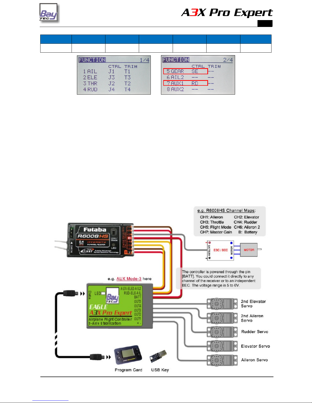
A 3-position switch (SE) is assigned to channel-5 for flight mode switching, which is implemented by using the
GEAR function in the radio system. A knob (RD) is assigned to channel-7 for the adjustment of master gain,
surely you might use a 3-position switch instead to get a 3-level gain control if you like.
6.4. Wiring
Connect all the required channels between the controller and the receiver, using the included plain 3-wire cables,
which have only one lead of the control signal on the receiver side, and are connected to the controller on the
combined connector. The controller requires at least 3 receiver channels, up to 7 channels. The channels of AIL,
ELE and RUD must be connected all the time otherwise the controller will not work. The other 3 pins should be
connected according to the AUX mode currently selected. The throttle servo or ESC is connected as normal to the
throttle channel of the receiver without bridging the controller. The illustration below shows the wiring method
only for AUX Mode-3, which is used in this case.
HTTP://WWW.BAY-TEC.DE Sept. 12, 2013
 Loading...