


BaySeparator
Technical and Design Manual
www.BaySaver.com

BAYSEPARATOR™ SYSTEM
T echnical and Design Manual
© BaySaver Technologies, Inc.
1302 Rising Ridge Road, Unit One
Mount Airy, Maryland 21771
Phone 301-829-6470 • Fax 301-829-3747
i

Table of Contents
Page
CHAPTER 1 – INTRODUCTION……………………………………………. 1
CHAPTER 2 - PRINCIPLES OF OPERATION…………………………….. 2
Hydrodynamic Separators………………………………………………………………………... 2
Mechanisms of Removal…………………………………………………………………………. 2
Overview of the Standard BaySeparator™ System……………...………………………………. 3
Single Structure BaySeparator™ Systems……………...………………………………............... 4
BaySeparator™ System Operation……………………………………………………………….. 5
Single Structure BaySeparator™ Operation…………...………………………………................. 8
CHAPTER 3 - COMPONENTS OF THE BAYSEPARATOR™ SYSTEM 16
BaySeparator™ Unit…………………………………………………………………….….......... 17
Primary and Storage Manholes………………………………………………………………….. 17
System Connections and Miscellaneous Piping…………………………………………………. 17
Single Structure BaySeparator™ Systems………………………………………………….......... 18
CHAPTER 4 – ENGINEERING AND DESIGN…………………………….. 19
Specifying BaySeparator™ Systems………………………………………………………..……. 20
Hydraulic Performance…………………………………………………………………………… 21
System Sizing…………………………………………………………………………………….. 22
Annual Aggregate Removal............................................................................................................ 22
CHAPTER 5 – INSTALLATION, MAINTENANCE AND CLEANING. ... 25
Installation Instructions………………………………………………………………………….. 25
Maintenance………………………………………………………………………………...……. 30
Inspection and Cleaning………………………………………………………………….………. 31
CHAPTER 6 - COST AND AVAILABILITY……………………………….. 33
APPENDICES………………………………………………………………….. 34
A. Specifications………………………………………………………………………………… 35
B. Engineering Drawings……………………………………………………………………….. 40
C. Project Information Sheet.…………………………………………………………………… 52
ii

BAYSAVER TECHNOLOGIES, INC.
Chapter
1
Introduction
Since 1997, BaySaver Technologies™ has been protecting lakes, streams, and waterways
from environmental problems. One of BaySaver Technologies’ most innovative products to control
non-point source pollution has been the BaySaver
installed in over 1,500 locations in commercial, industrial, and residential applications worldwide, and
has been used in projects as varied as parking lots, gas stations, service stations, maintenance
facilities, and highways. This separator has also been used as a pretreatment for other types of
stormwater technologies such as filters, ponds, infiltration systems, etc.
This manual provides an introduction to the BaySeparator™ line of products and the
technical details that will help you meet your stormwater pollution control requirements both now and
in the future.
®
Separation System1. The system has been
The BaySeparator™ was designed based upon the philosophy of the 3E’s: Efficiency, Ease of
Maintenance, and Economy. Through extensive laboratory testing and mathematical modeling we
have developed a separator that delivers predictable, reliable, and scalable performance based on third
party full scale testing.
The BaySeparator™ System makes complying with stormwater treatment regulations
nationwide convenient and cost effective. The BaySeparator™ system is a high performance
separator yet, its unique and simple design keeps it highly affordable, easy to specify, install, and
maintain. The BaySeparator™ is customizable to special project site conditions as either a standalone
or a pretreatment unit, and is ideal for use in retrofit situations. The BaySeparator™ has minimal
footprint requirements when compared to other types of Best Management Practices (BMPs).
The BaySeparator™ system begins operating as soon as runoff enters the system. During a
storm event, flow enters a Primary Manhole for initial separation. The flow is then conveyed to an
offline Storage Manhole where oils, fine suspended solids, and floatables are collected. Since the
water flow is regulated into the secondary manhole, resuspension is eliminated during higher flows.
In addition, the system’s chambers are fully accessible for inspection and maintenance from the
surface without entry to the system, resulting in more efficient maintenance and lower costs.
BaySaver Technologies, Inc. is committed to providing stormwater treatment solutions and
excellent customer service. If you have any questions about the information in this manual, please
contact BaySaver Technologies at 1-800-229-7283 (1-800-BaySaver) or by e-mail at
TechQuestions@BaySaver.com.
1
The BaySaver® Separation System is manufactured in Mount Airy, Maryland, by BaySaver Technologies,
Inc., and is protected by U.S. patent 5,746,911, several patents pending, and international patents. Any
infringement on these patents will be prosecuted to the fullest extent of the law. For detailed information on
specifying, purchasing, or installing a BaySaver
Inc. or an authorized representative directly.
®
Separation System, please contact BaySaver Technologies,
1

BAYSAVER TECHNOLOGIES, INC.
Chapter
2
Principles of Operation
Hydrodynamic Separators
Hydrodynamic separators rely on density differences and gravity to remove suspended solids
and floatables (hydrocarbons, floating debris, etc.) from stormwater runoff. The BaySeparator™
system splits water between two different manholes for optimal removal efficiency, responding to
changes in the influent flow rate. Pollutants are trapped in the two manholes until they are removed
by routine maintenance.
Mechanisms of Removal
The BaySeparator™ system removes pollutants from the stormwater stream through one of
two mechanisms: sedimentation or flotation. Engineers have relied on these two mechanisms in water
and wastewater treatment for years. The BaySeparator™ system applies these time tested principles
to stormwater treatment in a configuration that prevents contaminant release or resuspension during
high flow rates.
Sedimentation is the gravity-driven process by which solids suspended in water fall
downward. Sedimentation is driven by the difference in density between the solid particles and the
water surrounding it, and the size of the settling particles. Because they have more mass, larger
particles settle faster than smaller ones. The effectiveness of sedimentation depends on the size of the
settling particles and the length of time the particles are allowed to settle.
Flotation works the same way as sedimentation, but in the opposite direction. Floatable
pollutants like free oils and debris rise to the surface and are trapped in the storage manhole.
BaySeparator™ systems and other types of similar BMPs are typically sized to provide a
given annual aggregate removal efficiency. While hydrodynamic separators perform better at low
flow rates than they do at high flows, low flows are far more frequent than high flows. When
designed to achieve a specified annual aggregate removal efficiency, the BaySeparator™ system
operates at a high removal efficiency during the frequent, low intensity storms. Because the majority
of the sediment load from a site is contained in these more frequent storms, a BaySeparator™ system
designed in this way can remove 80% or more of the annual sediment load from a given site. The
BaySeparator™ can also be configured as a pretreatment BMP to filters, ponds, and other types of
BMPs as part of a treatment train.
2
BAYSAVER TECHNOLOGIES, INC.
o
Overview of the Standard BaySeparator™
System
The system is comprised of three main components: the BaySeparator™ unit, the Primary
Manhole, and the Storage Manhole. Figure 2.1 displays a simple schematic of the BaySeparator™
system. Influent flow containing pollutants enters the system by first passing through the Primary
Manhole. In this structure, coarse sediment settles while the flow passes over a weir into the
BaySeparator™ Unit and is routed to the Storage Manhole. The influent flow, at this point, still
contains pollutants of concern, such as fine sediments, oil, grease, floating trash, and other debris.
Once in the Storage Manhole floatable trash, oils, and grease float to the surface, while fine sediments
settle out and the influent separated flow returns to the outfall of the system back through the
Separator Unit.
Storage
Manhole
Floatables
Outlet To
Environment
Fine
Sediment
BaySeparator™ Unit
Coarse
Sediment
Primary
Manhole
Inlet Storm
NOTE: Second “Tee” pipe has
been removed for a clearer
view of the weir.
w
Fl
Figure 2.1: The BaySeparator™ System
As the rate of flow increases through the system, the BaySeparator™ unit acts as a dynamic
control to route the influent flow through the most effective flow path for treatment. For example,
under low flow conditions the entire influent flow is treated as described above. Under moderate
flows and up to the maximum treatment flow, water is continuously treated through both the Primary
and Storage Manholes, with a portion of these flows diverted through the T-pipes and the remainder
flowing into the Separator Unit and then to the Storage Manhole. This flow path allows for full
treatment of floatable pollutants, while still treating sediments under moderate flow conditions.
During maximum flow conditions, most of the influent flow passes over the bypass plate and will not
be treated.
3

BAYSAVER TECHNOLOGIES, INC.
Single Structure BaySeparator™ Systems
For some applications, site conditions or applicable regulations may require a single structure
hydrodynamic separator. For these projects, BaySaver Technologies can provide the BaySeparator™ SV, a
BaySeparator™ system contained in a single precast concrete vault. The BaySeparator™ SV is a selfcontained, single structure BMP that operates on the same principles and in the same manner as the standard
BaySeparator™ systems.
The BaySeparator™ SV is contained in a precast concrete vault. The vault is divided into two
separate chambers: a primary chamber and a storage chamber, which duplicate the functions of the precast
manholes. These two chambers provide a location for sedimentation and flotation to occur, and storage
capacity for the collected pollutants. Fine sediments and floatable pollutants are stored off-line, isolated
from high flows that may enter the system during extreme events, and the accumulated pollutants are
retained in the two chambers until they are removed by routine maintenance.
Internal flow controls divert influent water to achieve the best possible treatment efficiency in
response to the influent flow rate. These controls are constructed of HDPE, PVC, or stainless steel, and
include a surface skimming pipe that conveys influent water from the surface of the primary chamber to the
middle of the storage chamber; a return pipe that delivers treated water from the storage chamber to the
system outfall; a baffle in the primary chamber that prevents design flows from passing directly to the
system outlet; and a weir at the system outfall that allows flows up to the maximum treatment rate to pass
through the system without inundating the storage chamber and resuspending the pollutants collected there.
These flow controls also allow extreme flows to pass through the system unimpeded, thus minimizing the
risk of resuspending collected pollutants.
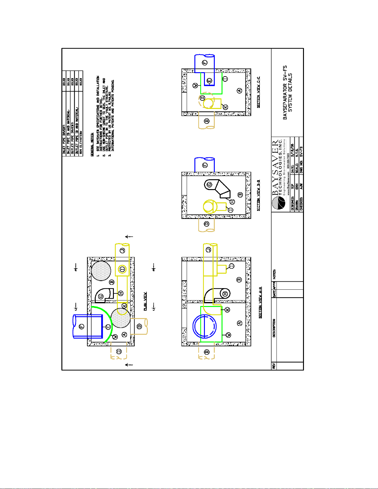
The BaySeparator™ SV is also available with built-in flow splitter design (BaySeparator™ SVFS). This configuration delivers treated effluent to a detention system or another water quality device via a
low flow while also diverting treated secondary flow to the low flow outlet as well. This outlet also allows
high intensity runoff to bypass the system through a separate overflow outlet pipe. The two effluent streams
can be directed to separate outfalls, or combined downstream and directed to a single outfall. Engineering
details for the BaySeparator™ SV-FS system can be found in Appendix B.
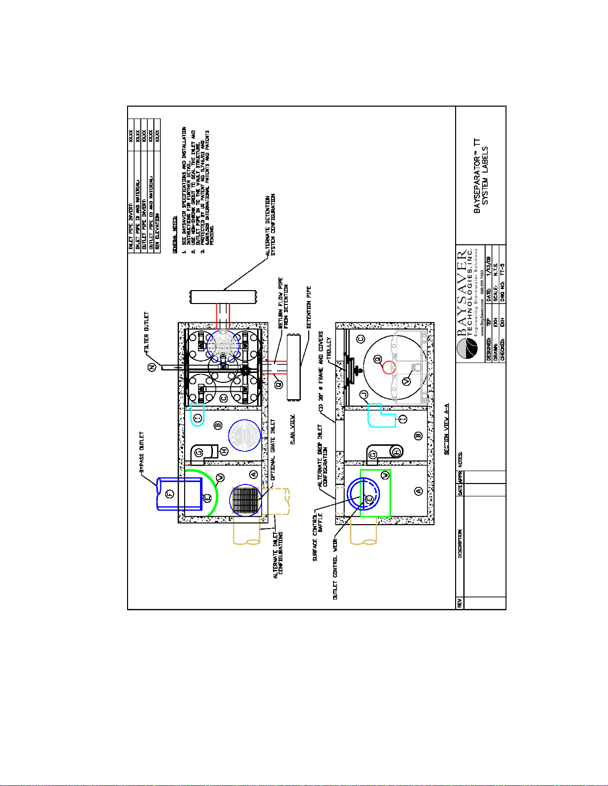
BaySaver Technologies, Inc. also manufactures an additional single structure system,
BaySeparator™ TT. The BaySeparator™ TT is constructed within a precast concrete vault. The
system comprises a modified BaySeparator™ SV-FS system and a third chamber that is used as the
housing structure for a BayFilter™ system. This third chamber also accommodates an attachment of
an underground storage system that retains the water quality volume on site.
4
BAYSAVER TECHNOLOGIES, INC.
y
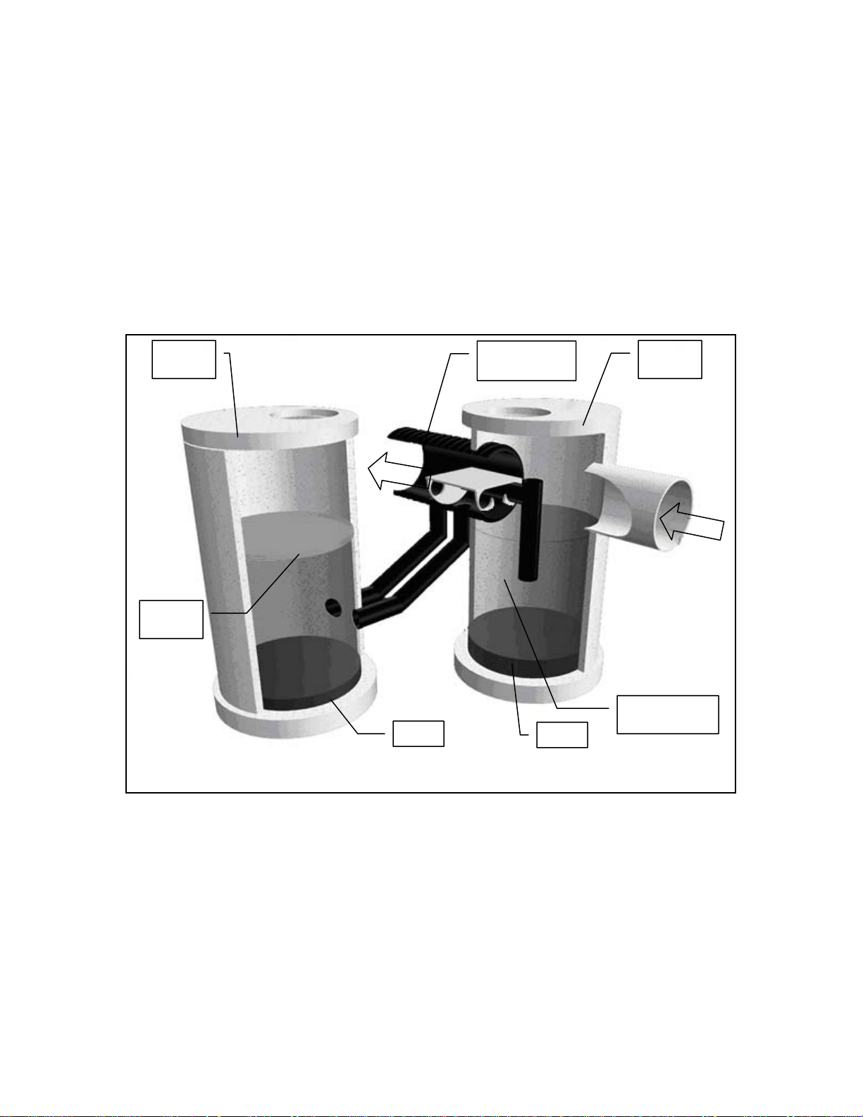
BaySeparator™ System Operation
Low Flows
During low flows, the BaySeparator™ System treats all the runoff through both manholes.
This occurs during small storms and the beginning of more intense storms.
Outlet Pipe from
Storage Manhole
Primary Manhole
Storage Manhole
Storage Manhole
Storage Manhole
Inlet Pipe to Storage
Manhole
Figure 2.2: Low Flow Operation
Note: Onl
one “T” pipe is shown in this drawing.
As shown in Figure 2.2, water enters the BaySeparator™ system’s Primary Manhole through the
inlet pipe shown on the right side of the figure. Coarse sediments (gravel and sand) immediately fall to the
floor of the Primary Manhole. The influent water, carrying floatables and finer sediments, flows through the
separator and is conveyed into the Storage Manhole (on the left), where it enters the structure below the
water surface. When water enters the Storage Manhole from the submerged inlet pipe, oils and other
floatables rise to the surface, while sediments settle to the floor. These contaminants remain trapped offline
and are not resuspended during larger flows. The influent water displaces clean water from the center of the
column, which is forced back up the return pipe to the system outfall. In this way, all of the water that
reaches the system outfall has been treated in both the Primary and Storage manholes.
5

BAYSAVER TECHNOLOGIES, INC.
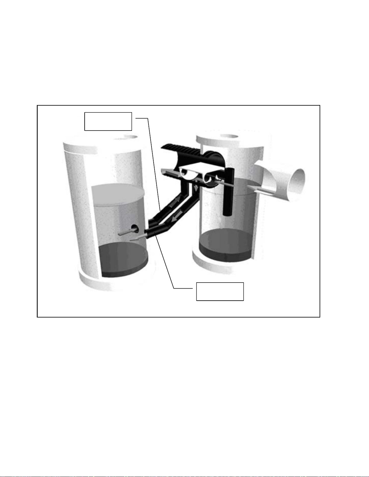
Maximum Treatment Flow
During larger storms, flow rates continue to increase. During these events, the
BaySeparator™ unit continues to divert surface flows (containing the majority of suspended
sediments, as well as the oils and other floatables) from
Manhole as described above (Figure 2.3).
the Primary Manhole to the Storage
“Tee” Pipes
Figure 2.3: Maximum Treatment Flow
Additional flows associated with the larger storm are treated by separation in the Primary Manhole.
As the pollutants are separated, the influent water displaces treated water from the center of the column and
forces it up the “Tee” pipes to the system outfall.
6
BAYSAVER TECHNOLOGIES, INC.
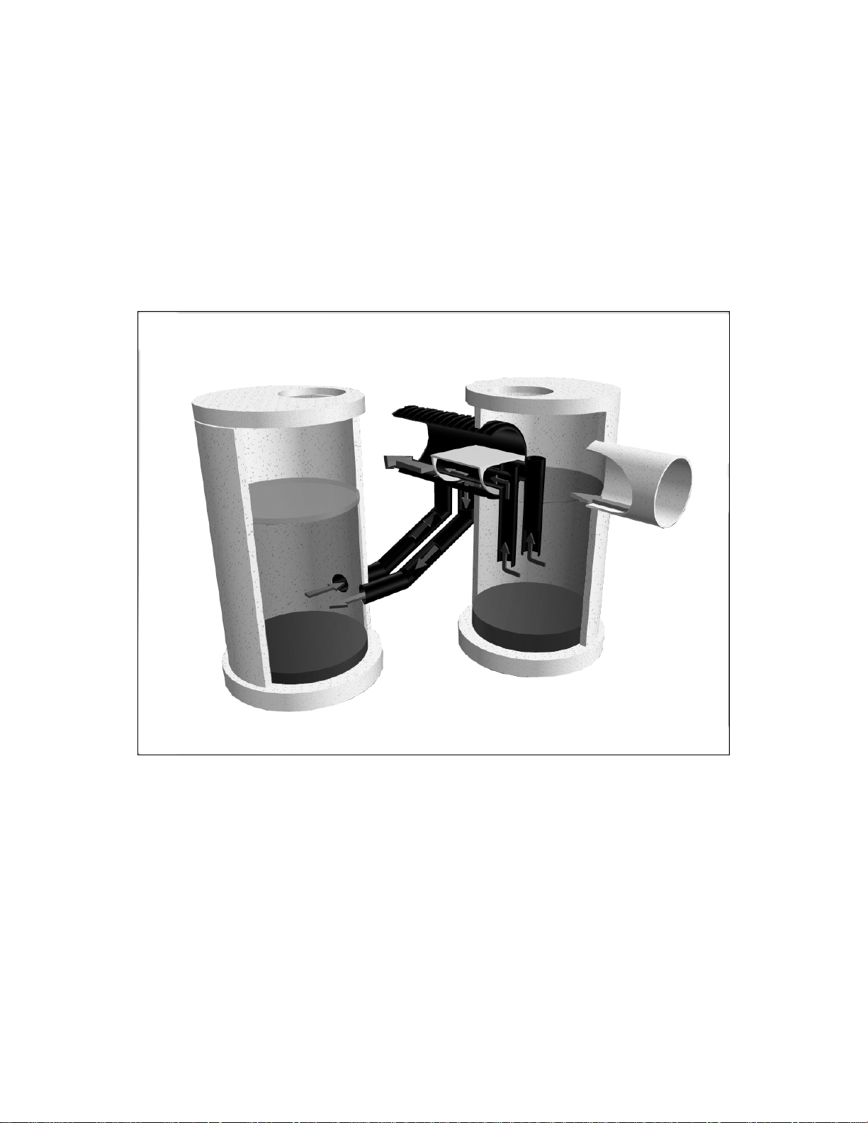
Peak Design Flow
The BaySeparator™ system also has an internal bypass to prevent flooding of the drainage area.
Influent flows with flood potential are directed over the bypass plate and directly through the unit. The
BaySeparator™ system uses the weir plate to limit flows into the Storage Manhole, minimizing the risk of
resuspending captured pollutants such as fine sediments, oils, and floatables that are stored offline. By
storing pollutants offline, the BaySeparator™ system hydraulically isolates these contaminants from
the high energy influent flows, effectively eliminating the risk of resuspending accumulated
contaminants
.
Figure 2.4 Peak Design Flow
Figure 2.4 shows the BaySeparator™ system near peak design flow. The open top “Tee”
pipes are engineered to minimize resuspension risks in the Primary Manhole. When the flow rate is
high enough to present the possibility of resuspension, water is allowed to flow into the top of the
“Tee” pipe. This limits the flow from the bottom of the pipe and minimizes turbulence in the center
of the Primary Manhole.
7

BAYSAVER TECHNOLOGIES, INC.
Single Structure BaySeparator™ Operation
BaySeparator™ SV Operation
During low flow conditions, influent water enters the BaySeparator™ SV through the Inlet pipe
(labeled D in Figure 2.5). It flows directly into the primary chamber (A), causing the water level in that
chamber to rise. When the water level in the primary chamber rises, water is skimmed from the surface of
that chamber by a pipe (G) that penetrates the wall between the two chambers. This pipe delivers that water
to the storage chamber (B), where it enters horizontally below the water surface through a 90 degree fitting
(H). When the water enters the storage chamber, the entrained sediments, floatables (oils, trash, debris)
separate from the water stream – sediments settle to the structure floor and floatables rise to the water
surface. The additional water in the storage chamber displaces clean water from the center of the column,
which enters the return pipe (I) and flows to the system outlet assembly (J). From here, the treated water
leaves the BaySeparator™ system.
When the flow rate into the BaySeparator™ system increases an additional flow path is created.
During this design treatment rate water in the primary chamber flows beneath the surface baffle plate (W).
The water that passes beneath this baffle is free of oils and floatable pollutants, which will continue to be
removed in the storage chamber. When the water level in the primary chamber rises high enough, this
cleaner water will flow over the weir (E) shown in the outlet assembly (J).
In extreme storm events, the flow rate into the BaySeparator™ system exceeds the maximum
treatment rate (MTR) of the SV unit. Under these rare conditions, the excess flow passes over the surface
baffle plate (W) and flows directly to the outlet assembly (J). Because the water level in the primary is
higher than the top of the weir, the weir no longer limits the flow to the system outlet. Instead, the high
flows pass directly over the walls of the outlet assembly (J) and enter the outlet pipe (F) directly.
8
BAYSAVER TECHNOLOGIES, INC.
g
ure 2.5: BaySeparator SV
Fi
9

BAYSAVER TECHNOLOGIES, INC.
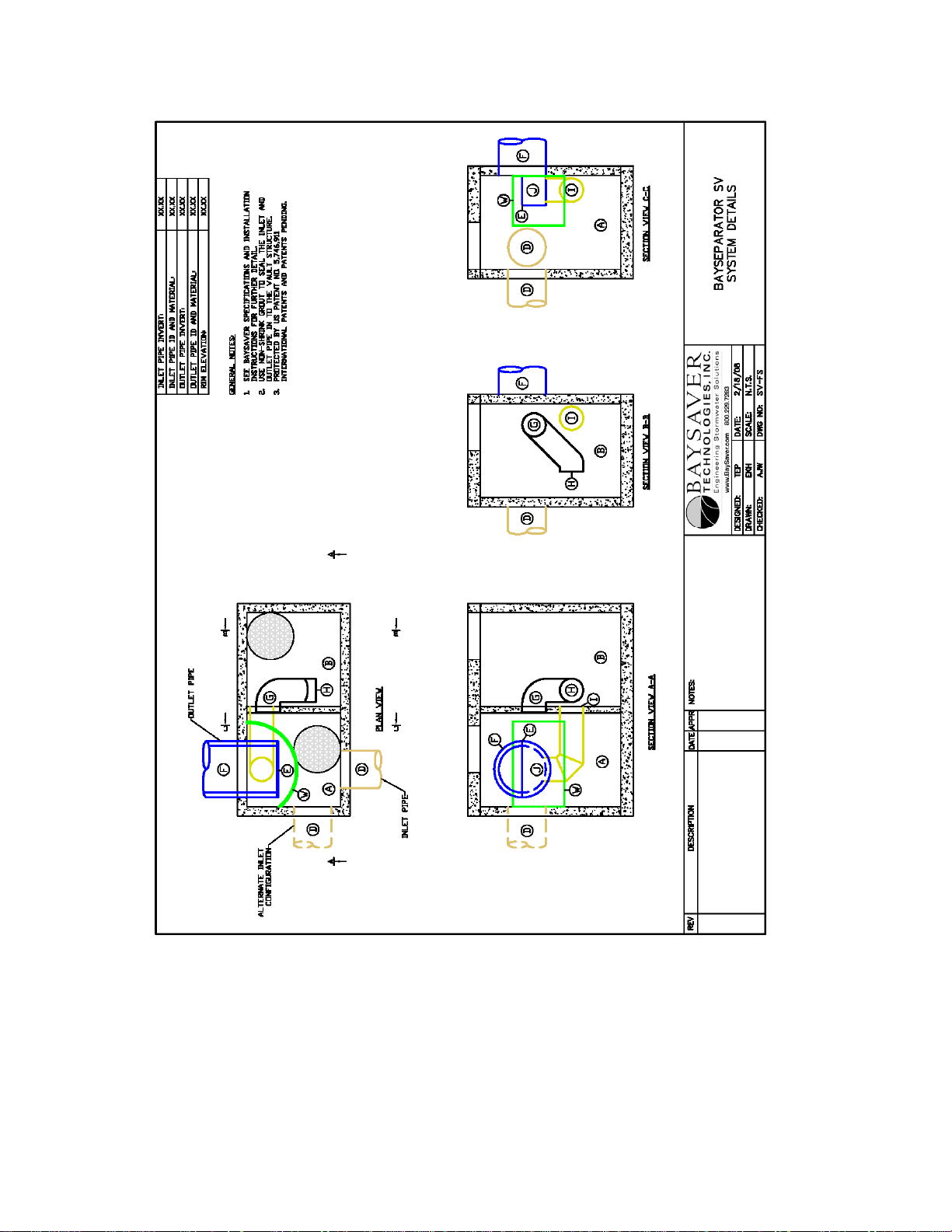
BaySeparator™ SV-FS Operation
pipe (labeled D in Figure 2.6), in the same manner as it does in the standard BaySeparator™ SV system. It
flows directly into the primary chamber (A), causing the water level in that chamber to rise. When the water
level in the primary chamber rises, water is skimmed from the surface of that chamber by a pipe (G) that
penetrates the baffle wall between the two chambers. This pipe delivers that water to the storage chamber
(B), where it enters horizontally below the water surface through a 90 degree fitting (H). When the water
enters the storage chamber, the entrained sediments and oils begin to separate from the water stream –
sediments settle to the structure floor and oils rise to the water surface. The additional water in the storage
chamber displaces clean water from the center of the column, which enters the return pipe (I) and flows to
the treated flow outlet assembly (J).
When the flow rate into the BaySeparator™ system increases an additional flow path is created.
When the water level in the primary chamber rises to a point higher than the horizontal invert of the tee-pipe
(K), water begins to flow into the tee-pipe (K) from below the water surface of the primary chamber. This
water is free of oils and other floatable pollutants, and it is conveyed through the tee-pipe to the treated water
outlet assembly (J). The geometry of the tee pipe limits the flow rate through this path in such a way as to
continue sedimentation in the primary chamber throughout design conditions.
In extreme storm events, the flow rate into the BaySeparator™ system exceeds the maximum
treatment rate of the SV-FS unit. Under these rare conditions, the excess flow passes over the surface baffle
plate (W) and flows directly to the overflow outlet pipe (F). The overflow outlet assembly (E) prevents
water from entering the overflow outlet during design flow conditions. When the water level in the primary
chamber rises high enough, however, excess water flows over the outlet assembly walls (E) and leaves the
system through the overflow outlet pipe (F).
During low flow conditions, influent water enters the BaySeparator™ SV-FS through the influent
10
BAYSAVER TECHNOLOGIES, INC.
Figure 2.6: BaySeparator™ SV-FS
11

BAYSAVER TECHNOLOGIES, INC.
BaySeparator™ TT Operation
(labeled D in Figure 2.7), in the same manner as it does in the BaySeparator™ SV. It flows directly into the
primary chamber (A), causing the water level in that chamber to rise. When the water level in the primary
chamber rises, water is skimmed from the surface of that chamber by a pipe (G) that penetrates the wall
between the two chambers. This pipe delivers the storage inflow water to the storage chamber (B), where it
enters horizontally below the water surface through a 90 degree fitting (H). When the water enters the
storage chamber, the entrained sediments and floatables separate from the water stream – sediments settle to
the structure floor and oils rise to the water surface. The additional water in the storage chamber displaces
clean water from the center of the column, and this storage outflow enters the return pipe (I) and flows into
the filtration chamber (C). The treated water enters the filtration chamber horizontally through a 90 degree
fitting on the end of the pipe (J).
When the flow rate into the BaySeparator™ system increases a second flow path is utilized. When
the water level in the primary chamber rises to a point higher than the horizontal invert of the secondary flow
pipe, water begins to flow into the secondary flow pipe from below the water surface of the primary
chamber. This secondary treatment flow is free of oils and other floatable pollutants, and it is conveyed
through the storage chamber via the secondary flow pipe. The geometry of the pipe limits the flow rate
through this path in such a way as to continue sedimentation in the primary chamber throughout design
conditions as well as to accommodate the low flow paths as outlined above.
During low flow conditions, influent water enters the BaySeparator™ TT through the inlet pipe
The low flow is released into the filtration chamber so as to ensure that the first flow is used to
“prime” the BayFilter™ cartridges to enable full cartridge flow to occur immediately. There is a one-way
(flap) valve (V) that prevents water from flowing into the detention pipes until after the water has reached a
depth that is sufficient to prime the filter cartridges. As water enters the filtration chamber, the valve will be
held shut by the pressure difference between this chamber and the water in the extended detention pipes
(This seal does not need to be “perfect”, a restricted condition is all that is necessary.) Once the water
elevation has reached 28”, the filters are primed and flow at the design rate will occur. At this point excess
water flow goes in to the extended detention pipe via an upper connecting pipe (Q). After the storm subsides
and the filter chamber drains down, the cartridges go into siphon, and the flap valve opens and releases the
water in the extended detention chamber into the filtration chamber.
For runoff flow rates up to the design treatment flow rate, 100% of the water that enters the
BaySeparator™ TT system is treated by both the physical processes of the BaySeparator™ itself and the
media filtration of the BayFilter™ system. When the influent flow rate is greater than the filtration capacity
of the BaySeparator™ TT system, but below the maximum treatment flow rate of the BaySeparator™ TT
unit, the excess water is diverted to the extended detention system, where it is stored until it can be released
to the filtration chamber at the lower flow rate. In the filtration chamber, the water is passed through the
BayFilter™ cartridges, and then collected in an under drain manifold and discharged through the outlet pipe
(N). Once the extended detention system is full, the treatment continues because as the water enters the
primary chamber (A), it must flow below the baffle (W) and then over the outlet weir (E) to the outlet pipe
(F).
12
BAYSAVER TECHNOLOGIES, INC.
Figure 2.7: BaySeparator™ TT
13

BAYSAVER TECHNOLOGIES, INC.
In extreme storm events, the flow rate into the BaySeparator™ system exceeds the maximum treatment rate
of the BaySeparator™ TT unit. Under these rare conditions, the excess flow passes over the surface baffle
plate (W) and flows directly to the overflow outlet pipe (F).
The BaySeparator™ TT-SO offers a slight variation from the “standard” TT unit.
Functionally, both units operate in a similar fashion, but the SO unit has a single outlet (F) instead of
two separate outlets. This single outlet (F) is located at the vault floor level of the primary chamber.
In the TT-SO unit, the filter outlet pipe (N) is connected directly to a standpipe (E), which is open at
the top, in the primary chamber. The elevation of this opening is the same as the elevation of the weir
in the standard TT unit. All effluent flows (both treated and bypass flows) from the TT SO unit enter
into a single outlet pipe (F). This TT SO unit may be used on sites where a single discharge point is
advantageous.
14

BAYSAVER TECHNOLOGIES, INC.
Figure 2.8: BaySeparator™ TT-SO
15

BAYSAVER TECHNOLOGIES, INC.
C
hapter
3
Components of the
BaySeparator™ System
The BaySeparator™ system comprises two standard precast manholes and the
BaySeparator™ unit. The two manholes allow the removal and storage of pollutants, while the
separator unit directs the flow of water to provide the most efficient treatment possible. Figure 3.1
shows a cutaway view of the complete BaySeparator™ system with flow patterns.
Figure 3.1: BaySeparator™ Flow Patterns
16

BAYSAVER TECHNOLOGIES, INC.
BaySeparator™ Unit
The BaySeparator™ unit is the heart of the BaySeparator™ system. The BaySeparator™ unit
controls the influent flow through the two manholes. This device is manufactured by BaySaver
Technologies’, and can be purchased through our locally authorized sales representative. Contact
BaySaver Technologies, Inc. for additional sales information.
The BaySeparator™ unit is fabricated entirely of high density polyethylene (HDPE) infused
with UV-resistant carbon-black. HDPE is a non-brittle, chemically inert material known for its
corrosion-resistant properties. It is commonly used in applications that expose it to harsh conditions
(landfills and chemical plants, for example) and is used in storm drains throughout the world.
The BaySeparator™ unit is constructed using state-of-the-art technology and the best materials
available ensuring quality construction. All parts are joined together with extrusion welding. The
BaySeparator™ unit is light, easy to install, and is provided with the connecting pipes and couplers needed
for a complete system (less the manholes)
Primary and Storage Manholes
The Primary Manhole is a standard precast structure used to remove coarse sediments. This
manhole is generally installed inline with the storm drain and can be used as a multiple inlet structure.
The precast manholes are purchased from local concrete distributors.
The Storage Manhole acts as a secondary treatment device for the collection and offline storage of
oils, fine sediments and floatables. It is also a standard precast manhole that is purchased locally. The
Storage Manhole is a key component that sets the BaySeparator™ system apart from other systems. The
BaySeparator™ system stores the pollutants offline to prevent resuspension.
System Connections and Miscellaneous Piping
The BaySeparator™ unit is connected to each of the two manholes with standard storm drain
pipe connections. The connecting pipes entering and leaving the storage manhole are submerged
during normal operation. Those joints must be watertight, and are typically made using flexible pipeto-manhole connectors (rubber boots) installed in the storage manhole by the precast manufacturer.
These connecting pipes are joined to the BaySeparator™ unit using Fernco® seals with shear rings.
The shear rings provide additional structural strength and rigidity to this joint. The BaySeparator™
unit is joined to the system outfall pipe with a custom made reducer/adapter provided by BaySaver
Technologies, Inc.
The connecting pipes are joined to the BaySeparator™ unit via a flanged connection. The
connecting pipe orientation (left or right hand) can be easily changed by removing the bolts in the
flange and rotating the connecting pipe to the desired unit orientation.
17

BAYSAVER TECHNOLOGIES, INC.
Single Structure BaySeparator™ Systems
BaySeparator™ XK systems, BaySeparator™ SV systems, and BaySeparator™ TT systems
contain internal components supplied by BaySaver™ Technologies, Inc. In BaySeparator™ XK
systems, these components are fabricated from stainless steel, and are joined to the walls of the
concrete vault structure using standard hardware provided by BaySaver™ Technologies. BaySaver™
supplies both mounting hardware and watertight seals (where necessary) for these installations.
BaySeparator™ SV and TT systems contain internal flow controls fabricated from HDPE and
PVC. Like the components of the XK systems, these flow controls are provided by BaySaver™
Technologies with the necessary mounting hardware and watertight seals. The component mounting
hardware and seals utilize standard utility connections, and are selected to meet all storm drain
construction specifications. The flow controls are designed to be easy for any experienced utility
contractor to install.
18

BAYSAVER TECHNOLOGIES, INC.
Chapter
4
Engineering and Design
BaySeparator™ units are manufactured in five (5) standard sizes (see Table 4.1). The
BaySeparator™ is also available in a custom configuration XK model for sites requiring higher flow
rates than the standard units, SV configurations for constrained sites that require a compact, single
structure unit, and a TT (treatment train) single structure unit that incorporates an SV BaySeparator™
coupled with an integral extended detention structure, and a BayFilter™ system with controlled
release.
The sizes of both the Primary and Storage Manholes in the BaySeparator™ may be varied to
suit specific site conditions and treatment requirements as necessary. By selecting the appropriate
separator unit size and determining the manhole diameters, the design engineer has the freedom to
adapt the BaySeparator™ unit to the needs of a particular site. The entire system can easily be
customized and hydraulically scaled to treat a wide array of stormwater flows varying from 1.1 cfs to
21.8 cfs with standard units. BaySaver Technologies can also accommodate significantly larger flows
by using the BaySeparator™ XK model.
Table 4.1: BaySeparator™ Hydraulic Performance
Characteristics
Standard
BaySeparator™
Model
Designation
1/2K
1K
3K
5K
10K
SV
SV-FS
TT-5 (TT-SO-5)
TT-8 (TT-SO-8)
XK
Note: cfs = cubic feet per second
BaySeparator™
Nominal
Diameter
(in inches)
24 1.1 8.5 48 6
24 2.4 10 48 8
36 7.8 30 60 8
48 11.1 50 72 8
60 21.8 100 120 8
24 5.3-23.1 16.0-101.8 48-96 4-6
24 5.3-23.1 16.0-101.8 48-96 4-6
24 2.8*/0.33** 16.0 48 4
24 2.9*/0.53** 16.0 48 4
Please contact BaySaver Technologies for design assistance
Maximum
Treatment
Rate
(MTR)
(in cfs)
*Maximum flow to extended detention, ** Maximum filtration rate
Maximum
Hydraulic
Rate
(MHR)
(in cfs)
Manhole
Diameter/
Length
Flow Based
Systems
(inches)
Manhole/
Vault
Depth
(in ft)
19

BAYSAVER TECHNOLOGIES, INC.
Specifying BaySeparator™ Systems
Location
The first step in specifying a BaySeparator™ system is determining where to place it. One of
the advantages of the BaySeparator™ system is its flexibility in site placement. The BaySeparator™
system can be configured as either a right- or left-hand unit to design around existing structures and
can be placed under load bearing surfaces or in green spaces. Looking downstream through the
system, if the Storage Manhole is placed to the left of the Primary Manhole, then a left-hand unit is
needed, and if the Storage Manhole is placed to the right of the Primary Manhole, then a right-hand
unit is needed.
For either pretreatment or full treatment flows that exceed the hydraulic capacities and/or
performance capability of the 60″ BaySeparator™, BaySaver Technologies BaySeparator™ XK
custom product line can accommodate higher hydraulic capacities and treatment flows to match a
special application. Call BaySaver’s Engineering Department at 1.800.229.7283 for sizing and design
information.
One of the most important considerations in specifying the site of the BaySeparator™ system
is choosing a location where inspection and maintenance access is readily available. The
BaySeparator™ systems can be designed downstream of multiple inlets or catch basins to reduce the
number of devices needed onsite, thus decreasing regulatory and maintenance costs.
BaySeparator™ systems are typically shown on site plans as shown in Figure 4.1.
BaySeparator™
System
Figure 4.1: Site Plan Example
The location of the BaySeparator™ on the site is determined by several factors. Maintenance
access, the unit’s footprint, available drop, available depth, and the surface elevation of the receiving
waters must be considered when selecting the system’s location.
The BaySeparator™ system must be installed in an area that is accessible to maintenance
equipment. The annual maintenance of a BaySeparator™ system requires a vacuum truck, and the
20

BAYSAVER TECHNOLOGIES, INC.
manhole covers of the BaySeparator™ must be placed in locations that can be easily reached by such
a vehicle.
The BaySeparator™ should be placed in a location that minimizes its interference with
existing or planned underground utilities.
Hydraulic Performance Characteristics of the
BaySeparator™
The BaySeparator™ system has two characteristic flow rates: the maximum treatment rate
(MTR) and the maximum hydraulic rate (MHR). The MTR is the maximum flow rate that can be
fully treated by the BaySeparator™ unit without any bypass. The MHR is the maximum flow rate that
can be conveyed through the BaySeparator™. The MHR, or bypass flow capacity, allows
BaySeparator™ systems to be installed online, without the need for a separate diversion structure.
Table 4.1 shows the MTR and MHR for each of the BaySeparator™ units.
BaySeparator™ systems can be designed for pretreatment (50% sediment annual aggregate
removal efficiency), for standalone / full treatment (80% annual aggregate removal efficiency), or for
other values of annual aggregate removal efficiencies. The design criteria used for each project will
depend on the applicable regulations of the jurisdiction in which the project site is located. Please
consult BaySaver Technologies’ Engineering Department at 1.800.229.7283 for special sizing
requirements or questions.
21

BAYSAVER TECHNOLOGIES, INC.
System Sizing
BaySeparators™ can be sized following different criteria which include:
1. Flow Based Sizing: This applies when a locality specifies the required treatment flow (MTR)
the separator has to treat together with the maximum hydraulic rate (MHR) associated with a
peak design storm. In some cases a treatment volume is given which then needs to be
converted to a flow using approved methods.
2. Annual Aggregate Removal (AAR) Based Sizing: This is a very common criteria used to size
hydrodynamic separators to a given suspended solids removal performance.
3. Other Sizing Criteria: Certain jurisdictions might have special sizing criteria that do not fit
the sizing criteria 1 or 2. In this case, BaySaver Technologies will work with the design
engineer and regulators to design a system meeting these local regulations or concerns.
Sizing by Flow Rate
To size the BaySeparator™ unit, the design maximum flow through the storm drain must first
be calculated. Compare that flow rate to the Peak Design Flow Rate listed in Table 4.1. Select a unit
with a Peak Design Flow Rate equal to or higher than the design flow. The unit selected and all larger
BaySeparator™ units have the capacity to convey the design flow without backup.
Local regulations may specify that a certain flow rate must be treated. In that case, compare the
Maximum Treatment Flow Rate with the treatment flow specified by the local regulations. Again, the
BaySeparator™ unit must have a maximum treatment flow rate (MTR) that is greater than or equal to the
determined treatment flow rate. This ensures that the BaySeparator™ unit will meet the local regulations.
Contact BaySaver Technologies for the recommended manhole sizes for flow based systems at
1.800.229.7283.
Example
:
Stormwater treatment is needed for a 3.2 acre site located in the US East Coast. The site has an
imperviousness coefficient of 0.85.
For this jurisdiction, the peak design flow is the 10-year 1-hour storm which is 2.6 inches. Using
the Rational Method, this translates into calculated peak flow of 7.07 cfs of runoff to be conveyed.
Using Table 4.1, we cross-reference this value against the Peak Design Flow Rates. The smallest
unit that can convey this peak design flow is a 1/2K BaySeparator™.
If local regulations require full treatment of the 1-year 1-hour storm which is 1.1 inches for this
location, this yields an average rainfall intensity of 1.1 inches per hour that need full treatment
resulting in a treatment requirement of 2.99 cfs. Again, using Table 4.1, we cross-reference this
value against the Peak Design Flow Rates. The smallest unit that can convey both the peak design
flow and the required treatment rate is a 3K BaySeparator™.
Annual Aggregate Removal
The performance of the BaySeparator™ system is dependent on not only the BaySeparator™
unit size, but also the diameter and depth of the Primary and Storage manholes. As described above,
hydrodynamic separators operate at varying efficiencies, depending on the treatment flow rate through
the separator. The sizing of the manholes is done by BaySaver Technologies, Inc, or the designer
using the BaySeparator™ Sizing Program. A general explanation of the procedure followed by the
sizing program is given next.
22

BAYSAVER TECHNOLOGIES, INC.
In the BaySeparator™ system, the removal efficiency is related to the flow rate by a general
logarithmic function shown below in Equation 1.
Q
MTR
⎞
b
⎟
⎠
⎛
mE +
∗= ln Equation 1
⎜
⎝
In Equation 1, E is the suspended solids removal efficiency of the system at the given flow
rate Q, (≤MTR) and the parameters m and b are characteristics of the particular BaySeparator™ unit.
To size BaySeparator™ systems to meet AAR efficiencies, more information about the site is
required. This sizing is done using the BaySeparator™ Sizing Program. In addition to the
characteristics of the BaySeparator™ system, the drainage area, runoff coefficient for the site, the
target TSS removal efficiency, and the maximum hydraulic rate (MHR) must be considered. The site
location must be entered to determine which precipitation record to use as the basis for AAR
calculations.
To calculate the AAR efficiency of a BaySeparator™ system, rainfall intensity is calculated
to correspond to the MTR for the chosen system (100% of fraction of MTR in Table 4.3). The
fraction of the total rainfall falling at or below that intensity is calculated for that maximum intensity
based on historical precipitation records. Increments (10%) of that intensity and a runoff flow rate are
then calculated for each of these increments. The fraction of the rainfall that generates a given runoff
flow rate is multiplied by the removal efficiency at that flow rate to find the fraction of the total
sediment removed under those conditions. Finally, the load reductions for each increment up to the
MTR of the BaySeparator™ unit are added together to give the AAR efficiency of the system. An
example of AAR calculations is shown in Table 4.3.
Scarsdale, New York
Drainage Area: 0.76 Acres
m = -0.3913
b = 0.3466
Fraction
of MTR
(percent)
10 99.0 0.11 43.6 43.1
20 97.6 0.22 23.5 23.0
30 81.8 0.33 12.3 10.1
40 70.5 0.44 6.7 4.7
50 61.8 0.55 5.5 3.4
60 54.6 0.66 2.5 1.4
70 48.6 0.77 1.4 0.7
80 43.4 0.88 1.2 0.5
90 38.8 0.99 0.9 0.3
100 34.7 1.10 0.7 0.2
Table 4.3: Calculation Example Annual Aggregate Removal Efficiency (AAR)
Removal
Efficiency
(percent)
Rainfall Intensity
(in/hr)
Aggregate Removal Efficiency: 87.4
Fraction of Rainfall
below Intensity
(percent)
Incremental
Efficiency
(percent)
23

BAYSAVER TECHNOLOGIES, INC.
Because AAR sizing calculations require precipitation data that may not be available to
designers, BaySaver staff can perform these calculations whenever they are required.
AAR-based BaySeparator™ designs take into account the typical precipitation patterns
throughout the United States. In most locations, the vast majority of precipitation falls at low
intensities, generating low runoff flow rates. In Baltimore, Maryland, for example, 80% of the total
precipitation falls at an hourly intensity of 0.37 inches per hour or less, and 95% of the total rainfall
comes at hourly intensities below 1 inch per hour.
Hydrodynamic separators usually function better at low flow rates, and the performance
degrades as the flow rate through the separator increases. Since the vast majority of precipitation falls
at low intensity and generates low runoff flow rates, this runoff is treated at a high efficiency. The
small fraction of the total precipitation that falls at higher intensities is still treated, but not with the
same efficiency that the majority of the runoff was treated.
When the majority of the runoff is treated to greater than 80% efficiency, and a small fraction is
treated less effectively, the end result is the net removal of still over 80% of the total sediment load.
24

BAYSAVER TECHNOLOGIES, INC.
Installation, Maintenance and
Cleaning
Installation Instructions
Overview
Chapter
5
BaySeparator™ systems are installed as part of the stormwater treatment system. The
BaySeparator™ unit and the system inlet pipe are grouted into the Primary Manhole using standard
storm drain connections. The connecting pipes entering and leaving the Storage Manhole require
watertight connections. These connections are made using standard boots or other locally approved
seals. Flexible couplers join the BaySeparator™ unit to the parallel inlet and outlet pipes (connecting
pipes) from the storage manhole. These flexible couplers account for differential settlement between
the two structures.
The pipes extending down from the separator (connecting pipes) must be backfilled with a free
flowing and self-compacting material such as pea gravel or 3/4" minus crushed stone. The remaining fill
material must be a Class I, II or III backfill and should be taken to at least 6" over the crown of the separator
unit.
The following Table 5.1 provides the minimum burial depths for the different separator models.
Table 5.1: Minimum Burial Depths
BaySeparator™ Diameter
(in inches)
24 12
36 12
48 12
60 24
Minimum Cover
For H-20 Load
(in inches)
25

BAYSAVER TECHNOLOGIES, INC.
Figure 5.1: BaySeparator™ Installation at a Typical Site
Contact the local utility and follow any special requirements regarding installation of
manholes and/or underground structures such as the BaySeparator™ unit. To demonstrate the
configuration of a standard BaySeparator™ System, an exploded view of the entire system is shown
below in Figure 5.2.
26

BAYSAVER TECHNOLOGIES, INC.
Figure 5.2: Exploded View of Standard BaySeparator™ System Components
27

BAYSAVER TECHNOLOGIES, INC.
Installation Instructions
1. Contact utility locator to mark underground utilities and to make certain it is safe to excavate.
2. Reference the site plan to determine the location of the BaySeparator™ system. Determine the
separator configuration (right-handed or left-handed), and compare it to the configuration
specified on the BaySeparator™ Detail Sheet. Looking downstream from the Primary Manhole,
determine whether the Storage Manhole is on the left or right side of the BaySeparator™ unit, and
determine whether the unit is properly configured as delivered. If the unit is not properly
configured, the stub pipes must be repositioned (see instruction 3). If correct, go to instruction 6.
3. Beginning with one flange, unscrew the nuts from each of the bolts. With the nuts removed,
lift the stub pipe vertically away from the body of the separator unit.
4. Turn the stub pipe 180 degrees from its original configuration.
5. Before placing the stub pipe back down on the unit, make sure that the gasket located between the
flanged end of the stub pipe and the flanged end of the separator unit, is sitting flush on the
separator unit flange, void of any wrinkles.
6. Place the stub pipe back down onto the unit. The bolts will pass directly back up through the holes
in the stub pipe flange.
7. In order to ensure a watertight seal between the stub pipe flange and the separator unit flange, the
bolts must be tightened in the following pattern and to the appropriate torque. Always use a
crisscross pattern for tightening. For example, tighten 1 to 20% of final torque, then tighten 2 to
20% of final torque, then tighten 3 to 20% of final torque, then tighten 4 to 20% of final torque,
and so on and forth until all bolts are tightened to 100% of the final torque. All bolts should be
tightened to a torque of 30 foot pounds.
Figure 10: Crisscross Pattern Diagram
8. Excavate to proper depth, length, and width in accordance with regulations to ensure safe site
conditions.
9. Level subgrade to the proper elevation and check against finished grade and structure dimensions
to ensure adequate depth.
10. Set the base of the Primary Manhole on approved subgrade.
11. Set the base of the Storage Manhole downstream as specified by dimensions on the
BaySeparator™ standard detail sheet and offset to either the left or right side as specified by
dimensions on the BaySeparator™ standard detail sheet.
12. Check the level of both the Primary and Storage Manhole bases and correct level if needed before
adding additional risers.
13. Add watertight seal (either mastic rope or rubber gasket) to the base of each manhole.
14. Set riser section on the base of each structure.
4
3
28

BAYSAVER TECHNOLOGIES, INC.
15. Add additional riser sections as previously detailed, until structures reach grade. Be sure to install
water tight seals.
16. Align the opening in the Primary Manhole for the separator unit with the proposed outlet to the
storm drain.
17. Align the inlet and outlet holes in the Storage Manhole so that they will be 90 degrees on center to
the separator unit.
18. Once the inlets and outlets for the Primary and Storage Manholes are properly aligned, backfill to
the bottom of the inlet and outlet of the Storage Manhole.
19. Insert the BaySeparator™ unit into the Primary Manhole. Be sure of the following:
A - The BaySeparator™ unit penetrates the inside wall of the Primary Manhole to a depth of
at least 1 corrugation.
B - The tee pipes of the BaySeparator™ unit are vertical and not skewed.
20. Support the body of the BaySeparator™ unit and level the unit so that there is no slope from the
front to the back of the separator unit.
21. Once the BaySeparator™ is level, insert the two connecting pipes into the inlet and outlet of the
Storage Manhole. Be sure the end of the connecting pipe labeled “IN” is inserted into the Storage
Manhole.
22. Line up the connector pipes with the stub pipes coming out of the bottom of the BaySeparator™
unit.
23. Tighten the watertight boots in the Storage Manhole onto on the connector pipes.
24. Tighten Fernco® couplers and shear rings on the joint between the stub pipes and the connector
pipes. (The 10K BaySeparator uses MarMac couplers to make this connection)
25. Backfill around the connector pipes up to the bottom of the separator unit using free flowing, selfcompacting material such as pea gravel or 3/4"or smaller crushed stone without fines
26. If the outlet pipe that is to be attached to the BaySeparator™ unit is of a different diameter than
the BaySeparator™, then a reducer/adapter (supplied by others) must be used to make the
connection.
27. Align reducer/adapter such that the small end of the reducer/adapter is in alignment with the outlet
pipe.
28. Use the larger Mar Mac (supplied by others) to couple the BaySeparator™ to the reducer/adapter.
Use the smaller Mar Mac (supplied by others) to couple the reducer to the outlet pipe. For further
information see instructions included with Mar Macs.
29. Using non-shrinking grout, seal the separator unit into the primary manhole.
30. Continue to back fill with Class I, II, or III material to at least 1’ above the crown of the 1/2K, 1K,
3K, and 5K; and 2’ over the crown for the 10K BaySeparator™ unit.
31. Install additional grade riser as needed and install frame and covers.
32. Backfill to grade using Class I, II or III backfill or other suitable material. Compact the backfill
according to geotechnical recommendations.
29

BAYSAVER TECHNOLOGIES, INC.
Maintenance
One of the advantages of the BaySeparator™ systems is the ease of maintenance. Like any
system that collects pollutants, the BaySeparator™ systems must be periodically maintained for
continued effectiveness. Maintenance is a simple procedure performed using a vacuum truck or
similar equipment. The systems were designed to minimize the volume of water removed during
routine maintenance, reducing disposal costs.
Contractors can access the pollutants stored in each manhole through a 30″ manhole cover.
This allows them to gain unobstructed access to the full depth of the system. There is no confined
space entry necessary for inspection or maintenance.
Vacuum hoses can reach the entire sump area of both manholes to remove sediments and
trash. The entire maintenance procedure typically takes less than an hour.
Local regulations may apply to the maintenance procedure. Safe and legal disposal of
pollutants is the responsibility of the maintenance contractor. Maintenance should be performed only
by a qualified contractor. Contact BaySaver Technologies Inc. at 1-800-229-7283 for a list of
approved contractors in your area.
30

BAYSAVER TECHNOLOGIES, INC.
Inspection and Cleaning
Periodic inspection is required to determine the need for and frequency of maintenance.
Inspections should be performed initially every six (6) months. Typically, the system needs to be
cleaned every 12 to 36 months, depending on site conditions. The system needs to be cleaned when 2
feet of sediment (1.5 feet for the 1/2K model) has accumulated in the bottom of either structure or
when visual inspection shows a large accumulation of debris or oil.
Measuring Sediment Depth
You can determine the sediment depth by lowering a pole into the manhole until it hits the
sediment and measuring the distance from the bottom of the pole to the water line mark on the pole. If
this is less than 6 feet (4.5 feet for the 1/2K model), the system needs to be cleaned.
Maintenance Instructions
1. For each BaySeparator™ system, there are 2 manholes to clean: the Primary Manhole and
Storage Manhole.
2. Remove the manhole covers to provide access to the pollutant storage.
3. Storage Manhole: Use a vacuum truck or other similar equipment to remove all water,
debris, oils, and sediment.
4. Storage Manhole: Use a high pressure hose to clean the manhole of all the remaining
sediment and debris. Then, use the vacuum truck to remove the rinse water.
5. Primary Manhole: Use a submersible pump to pump the bulk of the water from the Primary
Manhole into the clean Storage Manhole. Stop pumping when the water surface falls to one
foot above the accumulated sediments.
6. Primary Manhole: Use a vacuum truck or other similar equipment to remove all remaining
water, debris, and sediment.
7. Primary Manhole: Use a high pressure hose to clean the manhole of all the remaining
sediment and debris. Then, use the vacuum truck to remove the rinse water.
8. Both Manholes: On sites with a high water table or other conditions which may cause
flotation, it is necessary to fill the manholes with clean water after maintenance
9. Replace the two manhole covers.
10. Dispose of the polluted water, oils, sediment, and trash at an approved facility.
• Most local regulations prohibit the discharge of solid material into the sanitary
system. Check with the local sewer authority for any required permits and/or
conditions to discharge the liquid.
• Many places require the pollutants removed from BaySeparator™ systems to be
treated in a leachate treatment facility. Check with local regulators about disposal
requirements.
11. Additional local regulations may apply to the maintenance procedure.
This procedure is intended to remove all the collected pollutants from the system while
minimizing the volume of water that must be disposed. Additional local regulations may apply to the
maintenance procedure. Safe and legal disposal of pollutants is the responsibility of the maintenance
contractor; therefore maintenance should be performed only by a qualified contractor.
31

BAYSAVER TECHNOLOGIES, INC.
Summary
• Access the pollutants through the two manhole covers.
• See the entire floor/sump area of each manhole from the surface.
• No confined space entry for inspection or maintenance.
• During maintenance, transfer “clean” water from the Primary to the Storage Manhole,
minimizing the amount of water for disposal.
BaySaver
Technologies can assist in coordinating a maintenance contractor in the installation area,
or work directly with owners who wish to perform their own maintenance. Contact BaySaver Technologies
at 1-800-229-7283 (1-800-BaySaver) for more information
32

BAYSAVER TECHNOLOGIES, INC.
Chapter
6
System Cost and Availability
BaySeparator™ systems are available throughout the United States from BaySaver Technologies,
Inc. or from an authorized representative. Material, installation, and maintenance costs may vary
throughout the country. The BaySeparator™ System is your best value per treated CFS
regardless of your geographic location. For BaySeparator™ pricing in your area, please contact
BaySaver
directly.
Technologies Inc. at 1-800-229-7283 (1-800-BAYSAVE) or an authorized representative
The BaySeparator™ unit and materials can be shipped anywhere in the continental United States
within two weeks or less. Custom systems may require additional time. The system’s precast manholes need
to be ordered locally to arrive in conjunction with the BaySeparator™ Unit.
33

BAYSAVER TECHNOLOGIES, INC.
Appendices
Appendix A Stormwater Treatment Unit(s) Specification — Online System
Appendix B Engineering Drawings
Appendix C Project Information Sheet
34

BAYSAVER TECHNOLOGIES, INC.
A
Appendix
Stormwater Treatment
Unit(s) Specification —
Online System
35

BAYSAVER TECHNOLOGIES, INC.
STORMWATER TREATMENT UNIT(S) SPECIFICATION –
ONLINE SYSTEM
PART 1.00 GENERAL
1.1 DESCRIPTION
A.
Work Included:
The manufacturer selected by the Contractor and approved by the
Engineer, shall furnish all labor, materials, equipment and incidentals
required to manufacture the stormwater treatment system(s) specified
herein in accordance with the attached Drawing(s) and these
specifications.
1.2 QUALITY CONTROL INSPECTION
A. The quality of materials, the process of manufacture, and the finished
sections shall be subject to inspection by the Engineer. Such inspection
may be made at the place of manufacture, or on the worksite after
delivery, or at both places, and shall be subject to rejection at any time if
material conditions fail to meet substantially any of the specification
requirements. If a Stormwater Treatment Unit is rejected after delivery to
the site, it shall be marked for identification and removed from the site.
The Stormwater Treatment Unit(s) which have been damaged beyond
repair during delivery will be rejected and, if already installed, shall be
repaired to the Engineer’s and manufacturer’s acceptance level, if
permitted.
B. All sections shall be field inspected for general appearance, dimensions,
soundness, etc.
1.3 SUBMITTALS
A. Plan, elevation, and profile dimensional drawings shall be submitted to the
Engineer for review and approval. The Contractor shall be provided with
the approved plan, elevation, and profile dimensional drawings.
36

BAYSAVER TECHNOLOGIES, INC.
PART 2.00 PRODUCTS
2.1 MATERIALS AND DESIGN
Concrete structures shall be designed for H-20 traffic loading and
A.
applicable soil loads or as otherwise determined by a Licensed
Professional Engineer. The materials and structural design of the devices
shall be per ASTM C857 and ASTM C858.
1.
The minimum compressive strength of the concrete in the manhole
base, riser, and top sections shall be 4000 psi.
2.
The minimum wall thickness shall be one twelfth of the internal
diameter of the riser or largest cone diameter.
3.
Cement shall conform to the requirements for Portland cement of
Specification C150.
4.
Aggregates shall conform to Specification C33, except that the
requirement for gradation shall not apply.
5.
Reinforcement shall consist of wire conforming to Specification
A82 or Specification A496, of wire fabric conforming to
Specification A185 or Specification A497, or of bars of Grade 40
steel conforming to Specification A615/A615M.
6.
The access cover shall be designed for HS20-44 traffic loading and
shall provide a minimum 30 inch clear opening.
7.
All joints shall be waterproof with wrapped gaskets or sealed with
a mastic treatment.
8.
Any grout used within the system shall meet the ASTM C 1107
“Standard Specification for Packaged Dry, Hydraulic-Cement
Grout (Non-Shrink)”. Grades A, B and C at a pourable and plastic
consistency at 70ºF. CRD C 621 “Corps of Engineers
Specification For Non-Shrink Grout.”
9.
Storage manhole connector pipes shall be equipped with a seal
gasket that meets or exceeds material specifications of ASTM C923 or other locally approved methods.
B.
The separator structure shall be substantially constructed of HDPE or
equivalent corrosion resistant material meeting ASTM D330, ASTM
F412, and ASTM C-425.
C.
Pipes within the unit, (i.e., tee pipes, connector pipes and down pipes)
shall be constructed of at least SDR 32.5 HDPE pipe of standard ASTM
F412.
D. Pipe and fitting material shall be high-density polyethylene meeting
ASTM D330 minimum cell classification 335400C for 24-inch through
60-inch diameters. The 24- through 60- inch pipe material shall be slow
37

BAYSAVER TECHNOLOGIES, INC.
crack resistant HDPE material, evaluated using the single point notched
constant tensile load (SP-NCTL) test.
E.
The reducer/adaptor to the mainline shall be installed with an exterior
joining coupler. The joint coupler shall be Polyseal Pipe Coupler as
manufactured by Mar Mac Manufacturing Company or an approved equal
and shall be installed according to the manufacturer’s recommendations.
F.
The connector pipes shall be connected with the down pipes using
Fernco® Flexible Couplings that have been manufactured to conform to
ASTM C-425.
2.2 PERFORMANCE
A.
The stormwater treatment unit shall be an online unit capable of
conveying 100% of the design peak flow.
B.
The BaySeparator™ unit shall be designed to remove at least 80% of the
suspended solids load on an annual aggregate removal basis. Said removal
shall be based on full-scale third party testing using F-95 media gradation
(manufactured by US Silica) or equivalent. Said full scale testing shall
have included sediment capture based on actual total mass collected by the
Stormwater Treatment Unit (s).
C.
The stormwater treatment unit shall consist of one (1) prefabricated
separator structure, one (1) online coarse sediment capture structure, and
one (1) offline sediment and floatable capture structure. The separator
structure shall be substantially constructed of HDPE or equivalent
corrosion resistant material. The offline sediment storage structure must
provide for offline sediment storage of sediments and floatables that are
isolated from high intensity storms.
D.
The stormwater treatment unit(s) head loss at the Peak Design Flow Rate
shall not exceed the head loss specified by the Engineer.
E.
The unit shall be designed to remove sediment particles as well as floating
oils and debris.
2.3 MANUFACTURER
A. The stormwater treatment unit(s) shall be of a basic design that has been
installed and used successfully for a minimum of 5 years.
B. Each stormwater treatment system shall be a BaySeparator™ system as
manufactured by BAYSAVER
Mount Airy, MD 21771, Phone: (301) 829-6470, Fax: (301) 829-3747,
Toll Free: 1-800-229-7283 (1-800-BaySaver), E-mail: Info@BaySaver
Protected under U.S. Patent Number 5746911.
PART 3.00 EXECUTION
®
, INC., 1302 Rising Ridge Rd, Unit 1,
.
38

BAYSAVER TECHNOLOGIES, INC.
3.1 INSTALLATION
A. Installation of the Stormwater Treatment Unit(s) shall be performed per
manufacturer’s Installation Instructions. Such instructions can be obtained
by calling BaySaver Technologies, Inc. at 1.800.229.7283 or by login to
www.BaySaver.com
.
39

BAYSAVER TECHNOLOGIES, INC.
Appendix
B
Engineering Drawings
40

BAYSAVER TECHNOLOGIES, INC.
41

BAYSAVER TECHNOLOGIES, INC.
42

BAYSAVER TECHNOLOGIES, INC.
43

BAYSAVER TECHNOLOGIES, INC.
44

BAYSAVER TECHNOLOGIES, INC.
45

BAYSAVER TECHNOLOGIES, INC.
46

BAYSAVER TECHNOLOGIES, INC.
47

BAYSAVER TECHNOLOGIES, INC.
48

BAYSAVER TECHNOLOGIES, INC.
49

BAYSAVER TECHNOLOGIES, INC.
50

BAYSAVER TECHNOLOGIES, INC.
51

BAYSAVER TECHNOLOGIES, INC.
Appendix
C
Project Information Sheet
52

 Loading...