

Bayrol Pool Relax Chlorine, Pool Relax Oxygen, Pool Relax Bromine Instruction Manual
Pool Relax Instruction Manual, V1.0
Pool Relax
Instruction Manual
Chlorine
Bromine
Oxygen
Page 1 of 44

Pool Relax Instruction Manual, V1.0
Contents
1 INTRODUCTION ........................................................................................................................................5
2 INSTALLATION OF POOL RELAX ...........................................................................................................6
2.1 General Information.................................................................................................................................6
2.2 Selecting the Installation Location.........................................................................................................6
2.3 Mounting Pool Relax on the Wall...........................................................................................................6
2.4 Electrical Connection...............................................................................................................................7
2.4.1 Double Dosing Pump Lock ..................................................................................................................7
2.4.2 Earthing the Measurement Cell ...........................................................................................................7
2.5 Installation Plans......................................................................................................................................8
2.5.1 Pool Relax Chlorine Connection..........................................................................................................8
2.5.2 Pool Relax Oxygen connection............................................................................................................8
2.5.3 Pool Relax Bromine connection...........................................................................................................9
2.6 Putting into Operation.............................................................................................................................9
2.6.1 Pool Relax Chlorine.............................................................................................................................9
2.6.2 Pool Relax Oxygen............................................................................................................................10
2.6.3 Pool Relax Bromine...........................................................................................................................11
3 MAINTENANCE OF POOL RELAX .........................................................................................................12
3.1 Maintenance Plan...................................................................................................................................12
3.2 Dosing Pump Hoses..............................................................................................................................12
3.3 Electrode Information............................................................................................................................13
3.3.1 Electrode Wear..................................................................................................................................13
3.3.2 Electrode Care...................................................................................................................................13
3.3.3 Calibrating Electrodes........................................................................................................................13
3.4 Decommissioning / Winter Storage of the System.............................................................................13
4 OPERATING POOL RELAX ....................................................................................................................14
4.1 Overview of Features.............................................................................................................................14
4.1.1 Display and Operation........................................................................................................................14
4.1.2 Measuring and Control.......................................................................................................................14
4.1.3 Safety Functions
4.2 Operating principles..............................................................................................................................15
4.2.1 Keys ...................................................................................................................................................15
4.2.2 Cursor................................................................................................................................................15
4.2.3 Scrolling.............................................................................................................................................15
4.2.4 Making Entries...................................................................................................................................15
4.2.5 Additional Operating Functions..........................................................................................................16
4.3 Menu Structure.......................................................................................................................................16
5 GENERAL FUNCTIONS...........................................................................................................................18
5.1 Entry Code Number................................................................................................................................18
5.2 Customer Level......................................................................................................................................18
5.2.1 Configuration Menus..........................................................................................................................18
5.2.2 Global Configuration..........................................................................................................................19
5.2.3 Device Type Configuration.................................................................................................................20
5.2.4 PoolConnect Configuration................................................................................................................20
5.2.5 Event Log...........................................................................................................................................21
5.3 Info Page and Operating Notes.............................................................................................................21
5.4 Factory Level..........................................................................................................................................21
6 ALARMS ...................................................................................................................................................22
6.1 Overview.................................................................................................................................................22
6.2 Alarm Status...........................................................................................................................................22
................................................................................................................................14
Page 2 of 44

Pool Relax Instruction Manual, V1.0
6.3 Signalling................................................................................................................................................23
6.3.1 Flashing Headlines ............................................................................................................................23
6.3.2 Automatic Activation of the Alarm Page.............................................................................................23
6.3.3 Alarm Page........................................................................................................................................23
6.3.4 Acoustic Alarm Signal........................................................................................................................23
6.3.5 Blocking of Dosing.............................................................................................................................23
6.3.6 Potential-free Alarm Relay.................................................................................................................23
7 PH MEASURING AND CONTROL MODULE..........................................................................................24
7.1 pH Overview Page..................................................................................................................................24
7.2 pH Configuration....................................................................................................................................25
7.3 pH Calibration.........................................................................................................................................27
7.3.1 1-Point Calibration pH........................................................................................................................27
7.3.2 2-Point Calibration..............................................................................................................................28
7.3.3 Manual Setup of the Calibration Parameters.....................................................................................30
8 REDOX MEASURING AND CONTROL MODULE (MV) .........................................................................31
8.1 Redox Overview Page (mV)...................................................................................................................31
8.2 Redox (mV) Configuration.....................................................................................................................32
8.3 Redox (mV) Calibration .........................................................................................................................33
8.3.1 1-Point Calibration..............................................................................................................................33
9 TEMPERATURE MEASUREMENT .........................................................................................................34
9.1 Temperature Overview Page.................................................................................................................34
9.2 Temperature Configuration...................................................................................................................34
9.3 1-Point Calibration Temperature..........................................................................................................35
10 O2 AUTOMATIC DOSING SYSTEM ........................................................................................................36
10.1 O2 Overview Page...................................................................................................................................36
10.2 O2 Configuration.....................................................................................................................................37
11 DETAILED DESCRIPTION OF FUNCTIONS ..........................................................................................38
11.1 Control (pH, mV).....................................................................................................................................38
11.1.1 Proportional Range........................................................................................................................38
11.1.2 Calculating the Dosing Rate..........................................................................................................38
11.2 O2 Automatic Dosing System................................................................................................................39
11.2.1 O2 Automatic Dosing Without Temperature Compensation..........................................................39
11.2.2 O2 Automatic Dosing with Temperature Compensation................................................................39
12 ELECTRICAL CONNECTIONS................................................................................................................41
12.1 Connections on the Controller Housing..............................................................................................41
12.2 Connections in the Controller Housing...............................................................................................42
13 SERVICE ..................................................................................................................................................43
13.1 Controller Board.....................................................................................................................................43
13.1.1 Exchange of EPROMs (Software Update) ....................................................................................43
13.1.2 Changing the Buffer Battery..........................................................................................................43
13.1.3 Changing the Fuse........................................................................................................................43
13.1.4 PoolConnect Slot...........................................................................................................................43
13.2 Calibration Examples.............................................................................................................................44
13.2.1 1-Point Calibration ( pH )...............................................................................................................44
13.2.2 2-Point Calibration pH....................................................................................................................44
13.2.3 1-Point Calibration for Redox Electrode........................................................................................44
Page 3 of 44

Pool Relax Instruction Manual, V1.0
DANGER WARNINGS
Note: The dosing fluids used are corrosive and / or inflammable. Never allow the two ends of the pressure
hoses on vacuum pumps to hang loose, as this will permit the corrosive and inflammable fluids to escape.
During installation and operation, always observe the relevant health and safety regulations when installing and
using the device. The system should only be installed and put into operation by qualified expert personnel.
WARNING
Changing the system settings (default values) can be dangerous under certain circumstances. Therefore,
changes must only be made by trained technicians. The operator assumes liability if the equipment is used
improperly or the settings are modified incorrectly.
The system must be switched off immediately and protected against being switched on again if it probable that
the system cannot be operated safely and without danger.
This is the case, for example, if
• the system is visibly damaged,
• the system no longer appears to be functional for whatever reason,
• the system was stored for lengthy periods under unfavourable conditions (e.g. improper winter storage)
List of Abbreviations
pH pH value [pH], also abbreviation for pH control
mV Redox potential [mV], also abbreviation for redox control or measurement
T Temperature [°C/°F], also abbreviation of temperature measurement
D+ Dosage to raise pH / mV measurement
D- Dosage to lower pH / mV measurement
A/D converter Analogue/digital converter
LCD Liquid crystal display
LED Light emitting diode
Warning for preventing potential problems.
Page 4 of 44

Pool Relax Instruction Manual, V1.0
1 Introduction
Congratulations on the purchase of your Pool Relax measuring, controlling and dosing system. You have
decided for a device that greatly simplifies the care of your swimming pool with its high quality design and
operating reliability.
Regardless of which treatment method you have decided to use, your new Pool Relax will manage the water
quality in your pool.
Pool Relax is available as
Pool Relax Chlorine
For measuring and controlling pH and redox values, dosing of pH-Minus or pH-Plus (adjustable) and
ChloriLiquid.
Pool Relax Bromine
For measuring and controlling pH and redox values, dosing of pH-Minus or pH-Plus (adjustable). Bromine, a
water disinfection agent, is dissolved in a feeder and added as needed via a dosing valve.
Pool Relax Oxygen
For measuring and controlling pH and redox values, dosing of pH-Minus or pH-Plus (adjustable), and timecontrolled and temperature-compensated dosing of BayroSoft.
To obtain crystal clear water, Flockmatic can be used as an option with all three treatment variants. By
continuously adding the flocculant, the system even removes particles from the swimming pool water that
would otherwise simply pass through the sand filter of your system.
If you would like to have access to your Pool Relax system from anywhere, we recommend the use of
PoolConnect. With this GSM module, you can communicate with your system via SMS at any time. For
example, you can call up the water values or have the system send any alarms to your mobile phone.
Please read these instructions carefully to familiarize yourself with the system and how to operate it. If you
have any questions, please contact your dealer or the BAYROL Service Centre.
Page 5 of 44
Pool Relax Instruction Manual, V1.0
2 Installation of Pool Relax
2.1 General Information
Perform all installation work carefully and comply with the applicable safety regulations. During installation,
disconnect the measurement, control and dosing device and all other electrical loads such as the electrical
heating or the circulating pump from the mains.
In addition, comply with the applicable regulations regarding the installation of electrical devices.
General notes on installation:
• Ensure that the hoses are laid without kinking and that chafing cannot occur.
• Avoid laying the hoses over sharp edges.
• Carefully connect all hoses and check that the connections are firmly attached.
• Avoid unnecessarily long hose lengths.
• Do not guide the hoses directly over warm pipes or systems.
• Check that the float in the measurement chamber can float freely.
• Adjust the water flow through the cell so that the float just barely lies against the upper end in its guide
bore.
• If you are using a Flockmatic pump for dosing Quickflock Automatic+, please connect it to a
connection controlled by the circulating pump (circulation OFF – flocculation OFF; circulation ON –
flocculation ON)
2.2 Selecting the Installation Location
To mount Pool Relax, select a dry, frost-protected, sheltered and level location on a vertical wall. Ensure that
the area is readily accessible and well-ventilated. There should be no energized electrical cables, contactors,
electric motors, etc. in its vicinity. The installation location should be as close as possible to where the
measuring water is extracted and returned.
The supply voltage for the controller and the vacuum pumps should not exceed 240V/50Hz. The allowable
operating temperature range is from 0 to 50 OC, and the allowable humidity level equals 0-90 %.
If you are using a PoolConnect system, the installation location selected should have a good network
connection. If this is not possible, the antenna can be replaced by a more sensitive antenna or connected to
Pool Relax using a high quality extension cable (both of which are commercially available).
2.3 Mounting Pool Relax on the Wall
• The base plate with the mounted measurement cell can be used as a template by holding it up against the
mounting location and marking the drill holes on the wall.
• After the base plate is securely mounted on the wall, the controller housing is attached to the tongue and
groove joint provided for this purpose.
• The housing is attached using a slotted screw that can be accessed through an opening in the pump hood
holder.
Page 6 of 44
Pool Relax Instruction Manual, V1.0
• Connect the supplied pH pressure line on one side with the pressure side (right connector) of the left-hand
vacuum pump. Connect the other side with the upper
injection piece of the measurement cell. Ensure that the connection is tight and securely fastened.
• Connect the supplied pressure line for ChloriLiquid or BayroSoft on one side with the pressure side of the
right-hand vacuum pump. Connect the other side with the upper
injection piece of the measurement cell. Ensure that the connection is tight and securely fastened.
• Connect the flow switch and the temperature sensor (Pool Relax Oxygen only). Ensure that the connectors
are inserted in the sockets provided for this purpose (see the "Stickers on Controller Housing" and
"Connections on Controller Housing" chapters).
2.4 Electrical Connection
The system has been designed and constructed according to the applicable regulations. It was carefully
inspected before leaving the factory and left the factory in a perfectly safe condition.
The equipment can only be operated safely if all of the instructions contained in this manual are followed. The
equipment should be installed by a licensed electrician.
The supply voltage for the device may not exceed 240 V / 50 Hz. The allowable operating temperature range is
from 0 to 50OC, and the allowable humidity level equals 0-90 %.
Ensure that all plug-in connections are protected against water, as is standard practice for electrical
connections.
2.4.1 Double Dosing Pump Lock
Pool Relax is equipped with a double pump lock that offers a very high level of safety.
The flow switch in the measurement cell ensures that the dosing pumps can only be switched on if a sufficient
amount of water is flowing through the measurement cell.
In addition, the dosing pumps are supplied with the line voltage through a separate power supply. The power
supply must be switched in such a manner that the dosing pumps are only supplied with current when the
circulating pump is running.
In this way, dangerous dosing is prevented even in situations in which there is no flow, i.e. the system is doubly
safeguarded.
For connections, please see the "Connections on Controller Housing" chapter.
2.4.2 Earthing the Measurement Cell
The Pool Relax measurement cell is equipped with an earth screw that is used for diverting any potentials on
the pool water.
Note: The earthing provided for the plexiglass measurement chamber MUST be
installed. This earthing SHOULD NOT be laid into Pool Relax (earthing via the Pool
Relax power cable) but MUST be connected to a separate, secure earth. Make sure that
the earthing is functioning properly.
Always ensure that fault current is not flowing into the water of the swimming pool.
Professional measurement is recommended.
Page 7 of 44
Pool Relax Instruction Manual, V1.0
2.5 Installation Plans
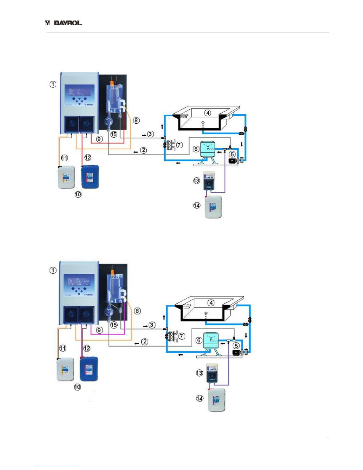
2.5.1 Pool Relax Chlorine Connection
1 Pool Relax Chlorine
2 Measurement water
intake
3 Measurement water
return
4 Swimming pool
5 Circulating pump
6 Sand filter
7 Heat exchanger
8 pH pressure line
9 ChloriLiquid pressure line
10 Containers for pH-Minus
and ChloriLiquid
11 pH-Minus suction line
12 ChloriLiquid suction line
13 Flockmatic (optional)
14 Quickflock Automatic+
canister (optional)
15 Prefilter
2.5.2 Pool Relax Oxygen connection
1 Pool Relax Oxygen
2 Measurement water
intake
3 Measurement water
return
4 Swimming pool
5 Circulating pump
6 Sand filter
7 Heat exchanger
8 pH pressure line
9 BayroSoft pressure line
10 pH-Minus and BayroSoft
containers
11 pH-Minus suction line
12 BayroSoft suction line
13 Flockmatic (optional)
14 Quickflock Automatic+
canister (optional)
15 Prefilter
Page 8 of 44

Pool Relax Instruction Manual, V1.0
2.5.3 Pool Relax Bromine connection
1 Pool Relax Bromine
2 Measurement water
intake
3 Measurement water
return
4 Swimming pool
5 Circulating pump
6 Sand filter
7 Heat exchanger
8 pH pressure line
9 pH pressure line
10 pH-Minus container
11 pH-Minus suction line
12 Bromine feeder
13 Flockmatic (optional)
14 Quickflock Automatic+
canister (optional)
15 Prefilter
16 Bromine magnetic valve
2.6 Putting into Operation
Before putting the system into operation, all previously described steps must be performed and the conditions
specified there must be met!
In addition, the containers with the water care agents must be connected to the system.
• To do so, connect the hose of the dosing lances with the suction side (left connector) of the respective
dosing pump. Ensure that the hose lengths are short and that the screw connections on the pump and
suction lance are firmly attached.
• Connect the BNC connectors of the suction lances with the respective socket on the controller (see also the
"Connection on Controller Housing" chapter).
2.6.1 Pool Relax Chlorine
• Bring the pH value of the pool water to 7.2. You can manually dose the pH to do so (see "pH Measuring and
Control Module"). If the pH value differs widely from 7.2, you can use pH-Minus/pH-Plus in a granular form
(it is important that you follow the dosing instructions on the product package). It is important that you check
the pH value with the supplied pool tester.
• After adjusting the pH value, bring the chlorine value of the swimming pool water to the desired level of free
chlorine (recommendation: 0.6 mg/l). You can manually dose the Cl to do so (see "Redox Measuring and
Control Module"). In large pools, you can also use Chlorifix (follow the dosing instructions on the product
packaging). It is important that you check the chlorine value with the supplied pool tester.
• When you adjust the pH and chlorine value of the pool water, you can simultaneously calibrate the pH and
redox electrodes with the buffer solution provided. Apply the 1-point calibration method for both electrodes.
• The redox value that results when the chlorine value of the pool water is adjusted (recommendation:
0.6 mg/l) can be used as the redox setpoint. A precondition is that the pH value must already be close to the
setpoint (+/- 0.1) and the redox electrode must be calibrated with the redox buffer.
ATTENTION: Use BAYROL water care products only!
Page 9 of 44

Pool Relax Instruction Manual, V1.0
• As soon as the pH and redox values in the pool water are close to the setpoints, you can set the control of
the two control modules to Auto.
• We recommend that you monitor the control behaviour over a period of time and adjust it to the conditions
prevailing in the pool, if necessary. In particular, this applies when the current values in the pool still vary
widely from the setpoints.
A PoolConnect module can be used for this purpose, which enables access to Pool Relax via a mobile
phone.
2.6.2 Pool Relax Oxygen
To ensure good water quality when treating water with BayroSoft, carefully adhere to the following
requirements.
A) Technical requirements
• Correct installation and operation of the pool’s hydraulic equipment, water supply (including overflow tank)
and filtering system
• The filter must operate for at least 10 hours/day
• Backwash at least once a week
• Sufficiently high backwash speed of 60 m/h and backwash time of at least 3 minutes
• Walls and floor of the pool must be cleaned regularly using a suction device – pool vacuum cleaner
• Filter sand must be checked regularly and replaced as necessary
B) Measures required in addition to dosing with BayroSoft
• Before putting the system into operation, administer a shock chlorination using 25 g of Chlorifix per cubic
metre of water. The chlorine should act for at least 3 days.
• A lined swimming pool with a new liner must be treated with chlorine for at least 14 days during which the
chlorine level must be kept constant at over 3 mg/l.
• After this period, start the BayroSoft treatment immediately and do not wait for the chlorine level to break
down.
• Regular flocculation with Superflock or the Flockmatic dosing device
(Quickflock Automatic+) is highly recommended.
• Occasionally check that BayroSoft is present in the water. If possible, do this on the day preceding the next
dosing (there should still be at least 10 mg/l of BayroSoft in the pool).
To check this, simply dip a BayroSoft QuickTest test strip into the water. A blue discolouration indicates that
BayroSoft is present.
C) Tips and tricks regarding inadequate water quality (BayroSoft)
Generally speaking, inadequate water quality is caused by a lack of BayroSoft in the swimming pool’s water
over a long period of time. Organic substances can build up in the water, resulting in cloudiness or causing the
swimming pool walls to become slippery. When this first occurs, check to see whether there is any BayroSoft in
the water. Dip a BayroSoft test strip in the water shortly before the next dosing takes place. The test strip must
at least turn light blue (corresponds to approx. 10 mg/l). If no trace of BayroSoft can be detected, increase the
dose amount so that BayroSoft is always present in the water.
D) How can the water quality be corrected?
• If the problem is just that the water is cloudy but the pool walls are not slippery, a double manual dosage
and the addition of a Superflock flocculation cartridge will be sufficient. The water quality will be correct by
the next day.
• If the water is cloudy and the pool walls are slippery, this indicates severe organic contamination and it will
be necessary to administer a single shock chlorination in order to return the water to the required quality.
Note: BayroSoft and chlorine neutralise each other, thereby rendering each other ineffective. Therefore, it
must be ensured that no BayroSoft remains in the water before applying chlorine. Otherwise the chlorine will
be ineffective. Use the BayroSoft test strips. An effective shock chlorination is only possible after there is no
blue discolouration, indicating that there is no more BayroSoft in the water.
Recommended dose amount for an effective chlorine shock: 1 tablet of Chloriklar per cubic metre or 25
grams of Chlorifix per cubic metre.
Page 10 of 44
Pool Relax Instruction Manual, V1.0
Important: When administering a shock chlorination, it is essential to clean the pool by mechanical
means in addition. Slippery deposits form a so-called "bio-film", which is not be completely eliminated even with
high concentrations of chlorine. As soon as the slippery deposit is destroyed by mechanical cleaning, the
chlorine can act and fully break down the organic contaminants. Resume BayroSoft water treatment at least
24 hours but no later than 48 hours after the chlorine shock is administered. You do not need to wait for the
chlorine levels to break down.
Procedure for Putting into Operation
• Bring the pH value of the pool water to 7.2. You can manually dose the pH to do so (see "pH measuring and
control module"). If the pH value differs widely from 7.2, you can use pH-Minus/pH-Plus in a granular form
(it is important that you follow the dosing instructions on the product package). Check the pH value with the
supplied Pooltester/BayroSoft test strips.
• Perform the shock chlorination specified under B).
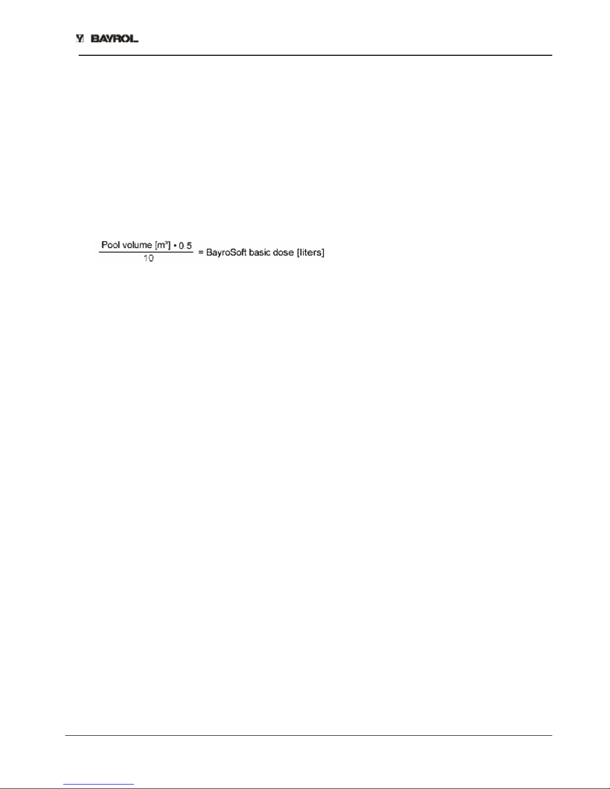
• Determine the basic dose according to the formula
and enter this value into the device as the basic dose.
• When you adjust the pH value or perform a shock chlorination, you can simultaneously calibrate the pH
electrode with the supplied buffer solution. Apply the 1-point calibration method.
• As soon as the pH value is close to the setpoints, you can set the control of the pH value and the O2
automatic dosing system to Auto. At high water temperatures, also activate the temperature compensation
(see "Configuration O2" and "Functional Description O2").
• We recommend that you monitor the control behaviour over a period of time and adjust it to the conditions
prevailing in the pool, if necessary.
A PoolConnect module can be used for this purpose, which enables access to Pool Relax via a mobile
phone.
• In any case, it is necessary that you check the BayroSoft content in the pool water using the supplied
BayroSoft test strips. Shortly after the main dosing, the measured value should equal 35-50 mg/l (dark blue
colour) and shortly before the next main dosing the value should equal at least 10 mg/l (light blue colour).
2.6.3 Pool Relax Bromine
• Bring the pH value of the pool water to 7.2. You can manually dose the pH to do so (see "pH measuring and
control module"). If the pH value differs widely from 7.2, you can use pH-Minus/pH-Plus in a granular form
(it is important that you follow the dosing instructions on the product package). It is important that you check
the pH value with the supplied pool tester.
• First bring the bromine value of the swimming pool water to the desired value. (Recommendation: 2-4 mg/l).
ATTENTION: Depending on the pool size and water temperature, this bromine value may not reach its final
level until after several days. To ensure a sufficient degree of water disinfection from the beginning, we
recommend an initial disinfection with chlorine, e.g. with Chlorifix. It is important that you check the bromine
value with the supplied pool tester.
• When you adjust the pH and bromine value of the pool water, you can simultaneously calibrate the pH and
redox electrodes with the supplied buffer solution. Apply the 1-point calibration method for both electrodes.
• The redox value that results when the bromine value of the pool water is adjusted (recommendation:
2-4 mg/l) can be used as the redox setpoint. A precondition is that the pH value must already be close to
the setpoint (+/- 0.1) and the redox electrode must be calibrated with the redox buffer.
• As soon as the pH and redox values in the pool water are close to the setpoints, you can set the control of
the two control modules to Auto.
• We recommend that you monitor the control behaviour over a period of time and adjust it to the conditions
prevailing in the pool, if necessary. In particular, this applies when the current values in the pool still vary
widely from the setpoints.
A PoolConnect module can be used for this purpose, which enables access to Pool Relax via a mobile
phone.
Page 11 of 44
Pool Relax Instruction Manual, V1.0
3 Maintenance of Pool Relax
3.1 Maintenance Plan
Monthly maintenance:
• Visually inspect all dosing lines and hoses for leakages
• Check the filter sieve and clean it if necessary
• Check the water values with the supplied test kit and readjust the settings if necessary
Quarterly maintenance:
• Visually inspect all dosing lines and hoses for leakages
• Check the filter sieve and clean it if necessary
• Check the water values with the supplied test kit and readjust the settings if necessary
• Calibrate the pH and redox electrodes using the supplied buffer solutions
Annual maintenance:
• Visually inspect all dosing lines and hoses for leakages
• Check the filter sieve and clean it if necessary
• Check the water values with the supplied test kit and readjust the settings if necessary
• Replace and calibrate the pH and redox electrodes using the supplied buffer solutions
• Replace the hoses of the dosing pumps
ATTENTION: Disconnect all power connections before beginning maintenance work!
3.2 Dosing Pump Hoses
The hoses of the dosing pumps must be replaced annually or earlier if worn. Use original replacement hoses
only. They can be obtained from your swimming pool dealer.
The following hoses may be used:
171 219 Replacement hose set 0.9 l/h (for chlorine and pH-Plus/pH-Minus, recognizable by the white nozzles)
171 216 Replacement hose set 6.0 l/h (for BayroSoft, recognizable by the black nozzles)
Hose Replacement
To replace the hoses, proceed as follows:
• Rinse the pump with fresh, lukewarm water for about 30 minutes. To do so, place the suction lances into a
pail filled with tap water and start a manual dosing.
• Ensure that the system is fully disconnected from the power grid. This prevents the pump from switching on
during the maintenance procedure.
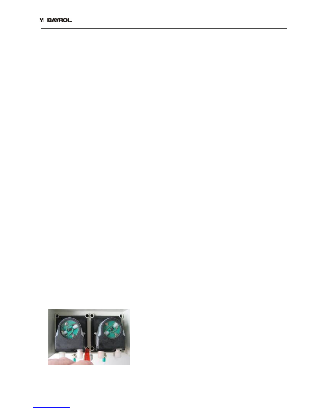
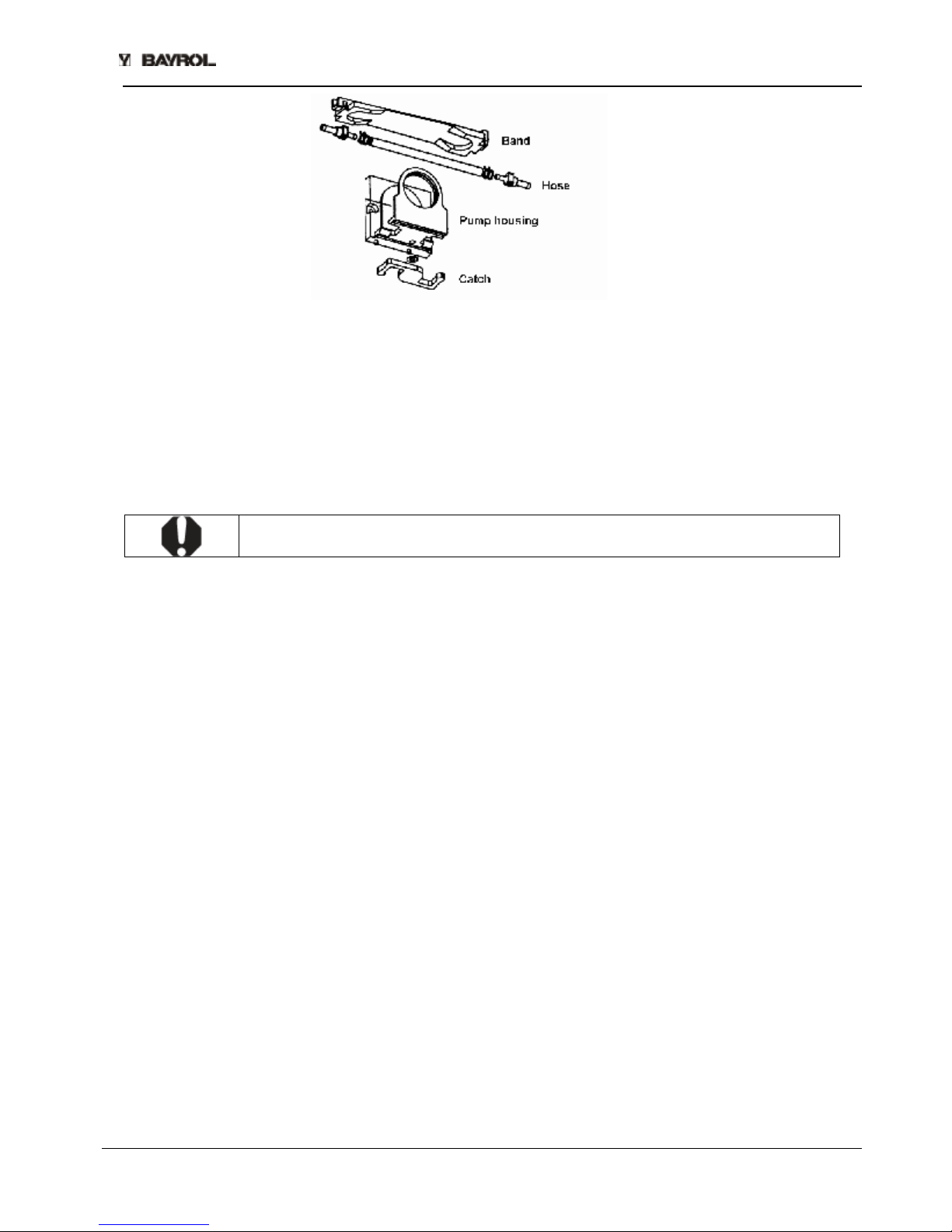
• Lift the blue covers from the pumps and remove the suction and pressure hoses.
• Press the band together at the recessed grips and turn the catch clockwise all the way.
• Move both hose ends outward and remove the band with the hose.
• Pull the old hose out of the two guides and insert the new hose.
• To mount the hose band and hose, proceed in reverse order. Ensure that the hose is firmly seated in the
guides and that the catch has engaged.
• As soon as all connections have been closed, you can purge the air from the dosing hose. To do so,
connect Pool Relax with the mains and start a manual dosing.
Page 12 of 44
Pool Relax Instruction Manual, V1.0
Figure: Top of the pump
3.3 Electrode Information
The electrodes must be replaced annually or earlier if worn. Use original replacement electrodes only. They
can be obtained from your swimming pool dealer.
3.3.1 Electrode Wear
The following conditions, among others, indicate that the electrodes are worn:
• During calibration, the electrode takes unusually long to reach the value of the buffer solution.
• The electrode offset during calibration is too large.
• The KCL solution in the electrode shaft is used up or discoloured.
ATTENTION: Electrodes wear very rapidly if there is an electric potential in the pool water!
3.3.2 Electrode Care
• The pH-sensitive membrane glass must be handled with care and protected against damage.
• The inner reference solution in the glass electrode must cover the inner surface of
the membrane glass. Any air bubbles are removed by gently shaking the electrode vertically (like shaking a
medical thermometer).
Contamination deposited on the surface of the membrane glass must be removed by carefully wiping it with a
moist paper towel. Alternatively, you can use the supplied electrode cleaning solution.
3.3.3 Calibrating Electrodes
Notes on calibrating electrodes can be found in the corresponding chapters and in the calibration examples.
3.4 Decommissioning / Winter Storage of the System
If the system is put out of operation for lengthy periods, e.g. for winter storage, certain precautionary measures
need to be taken. In particular, it is very important that the entire system is protected against freezing
temperatures and humidity.
Dosing System
• Rinse the pump with fresh, lukewarm water for about 30 minutes. To do so, place the suction lance into a
pail filled with tap water and start a manual dosing.
• Ensure that the system is fully disconnected from the power grid.
• Release the hose set to prevent permanent deformation.
Measuring System
• Store the electrodes in an upright position in the containers in a location where temperatures will not drop
below zero. The three molar KCL solution in the containers protects the electrodes from drying out.
• Close both electrode drill holes of the measurement cell with the supplied cover screws.
• Let the water drain from the measurement chamber and measurement lines.
Page 13 of 44
Pool Relax Instruction Manual, V1.0
4 Operating Pool Relax
4.1 Overview of Features
4.1.1 Display and Operation
• 4-line multifunctional LC display, bluemode (4 x 20 characters)
• Simple 6-key operation
• Clear menu structure
• Menus can be displayed in a variety of selectable languages
4.1.2 Measuring and Control
• Proportional control for all control modules
• All important control parameters can be programmed individually for each control module (setpoint,
maximum dosing time, proportional range, dead zone (pH), basic dose (mV), minimum switchedon/switched-off time)
• Continuous display of current dosing rate
• Conversion of all measurements by high resolution 10-bit analogue/digital converters
• 1- or 2-point calibration for pH measurements
• 1-point calibration of mV and T measurements
4.1.3 Safety Functions
• Comprehensive monitoring and alarm functions
(upper and lower threshold alarms, flow alarm, level alarms, dosing time alarms, calibration time alarms,
battery alarm, power-on delay, automatic blocking of dosing during critical alarm conditions and during
power-on delay, alarm notification through
Ø display
Ø acoustic alarm signal
Ø potential-free relay for external alarm outputs
• continuous monitoring of the correct program sequence and automatic reset in the event of an error
(watchdog function)
• Double dosing pump lock
Pool Relax is equipped with a double pump lock that offers a very high level of safety.
The flow switch in the measurement cell ensures that the dosing pumps can only be switched on if a
sufficient amount of water is flowing through the measurement cell.
In addition, the dosing pumps are supplied with the line voltage through a separate power supply. The
power supply must be switched in such a manner that the dosing pumps are only supplied with current
when the circulating pump is running.
In this way, dangerous dosing into stationary water is prevented even if one of the two fuses should blow
due to external causes.
• Alternating switching on of the dosing pumps
As soon as a dosing pump starts running, the other pump is blocked. This prevents the agents for raising or
lowering the pH from being dosed together with the water disinfection agent (ChloriLiquid or BayroSoft).
Because perfect water disinfection is only possible at a pH value of 7.2, dosing of the agents for raising and
lowering the pH takes precedence over dosing of the water disinfection agent.
ATTENTION: pH-Minus and ChloriLiquid should never come into contact with each
other – Danger of chlorine gas!
Page 14 of 44
 Loading...