

Bayrol PoolManager, PoolManager Oxygen, PoolManager Chlorine, PoolManager Bromine, PoolManager PRO User Manual
Page 1
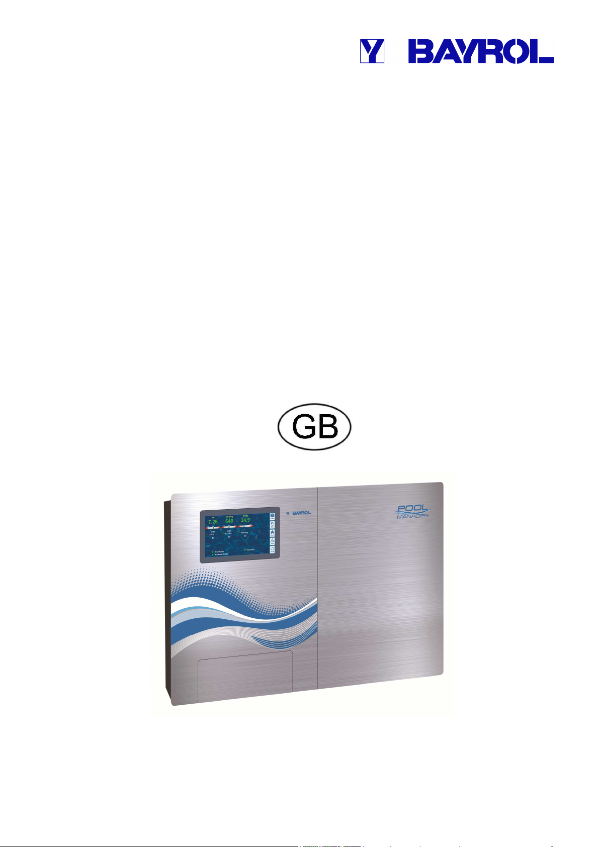
User Manual
for the Measurement, Control, and Dosage System for
Swimming Pools
®
PoolManager
PoolManager® Chlorine
PoolManager® Bromine
PoolManager® Oxygen
PoolManager® PRO
Page 2

Content
Content
Part A: Overview .............................................................................. 6
1 Identification of safety information ..................................... 6
1.1 Safety information ................................................................ 6
1.2 Miscellaneous markings ....................................................... 6
2 General safety information................................................... 6
3 User qualification .................................................................. 7
4 Term definitions .................................................................... 8
5 Standard access codes ........................................................ 8
6 Overview ................................................................................ 9
6.1 PoolManager® ...................................................................... 9
6.2 Maintenance program .......................................................... 9
6.3 Overview of features ............................................................ 9
6.3.1 Display and operation 9
6.3.2 Measuring and control 9
6.3.3 Safety functions 10
6.3.4 Add-on functions 10
6.3.5 Remote access from the local network or the Internet 10
6.3.6 Interfaces 11
Part B: Function description ........................................................ 12
7 Remote access .................................................................... 12
7.1 Prerequisites ...................................................................... 12
7.2 Remote access to the local network .................................. 12
7.2.1 Step by step 12
7.3 Remote access from the Internet ....................................... 12
7.3.1 Step by step 12
7.4 User login in remote access............................................... 12
7.5 Quick info ........................................................................... 12
7.5.1 Calling up quick info 13
8 Display and operation - Graphical user interface ............ 13
8.1 Important menus ................................................................ 13
8.1.1 Home view 13
8.1.2 Main menu (icon menu) 14
8.1.3 Add-on functions menu (icon menu) 15
8.1.4 Mode menu 16
8.2 Further menus (standard menus) ...................................... 16
8.2.1 Basic concepts 16
8.2.2 Numerical parameters 16
8.2.3 Selection parameters 17
8.2.4 Text parameter 18
8.2.5 Time parameters 19
8.2.6 Date parameter 19
8.2.7 Access code 20
8.2.8 Network (IP) addresses 20
8.2.9 Messages 21
8.2.10 Menu functions 21
8.2.11 Menu sequences 21
8.3 Help .................................................................................... 22
8.4 Informational text ................................................................ 22
8.5 individualisation .................................................................. 23
8.5.1 Menu style 23
8.5.2 Background image 23
8.5.3 Icon style 23
9 Measured value graph ......................................................... 24
9.1 Overview ............................................................................. 24
9.2 Notes on Measurement graph: ........................................... 25
9.3 Configuration ...................................................................... 25
9.4 Measurement graph export ................................................ 26
10 Water maintenance .............................................................. 26
10.1 pH value .............................................................................. 26
10.2 Disinfection ......................................................................... 26
10.2.1 Free chlorine/bromine 26
10.2.2 Redox value (Disinfection with chlorine and bromine) 27
10.2.3 Correlation pH value and disinfection 27
10.2.4 Active oxygen (BayroSoft) 28
11 Measurement, control, dosage (pH value, redox value,
chlorine/bromine)................................................................. 28
11.1 Function .............................................................................. 28
11.2 Dosage rate ........................................................................ 28
11.3 Display in home view .......................................................... 29
11.4 Configuration parameters ................................................... 29
11.4.1 Setpoint 29
11.4.2 Lower alarm threshold 29
11.4.3 Upper alarm threshold 29
11.4.4 Proportional range 29
11.4.5 Minimum dosing rate 30
11.4.6 Intelligent dosing monitoring 31
11.4.7 Dead zone 31
11.4.8 Dosing cycle 31
11.4.9 Dosing direction 32
11.4.10 Recommended settings 32
11.4.11 Recommended settings for PoolManager® PRO 32
11.5 Configuration assistant ....................................................... 32
11.5.1 Basics 32
11.5.2 Configuration assistant 33
12 Calibration (basic measurement comparison) ................. 33
12.1 When is calibration necessary? .......................................... 33
12.2 pH calibration ...................................................................... 33
12.2.1 Execution 34
User Manual PoolManager® 2
Page 3

Content
12.2.2 Calibration errors 35
12.3 Calibration chlorine (Cl) / bromine (Br) (just PoolManager®
PRO) .................................................................................. 35
12.3.1 Execution 35
12.3.2 Calibration errors 36
12.4 Calibration redox (mV) ....................................................... 36
12.4.1 Execution 36
12.4.2 Calibration errors 37
12.5 Determining the redox (mV) setpoint ................................. 37
12.5.1 Step by step 37
13 Automatic dosage O2 (BayroSoft) .................................... 38
13.1 Basic concept ..................................................................... 38
13.1.1 Main dosage 38
13.1.2 Refresh dosages 38
13.1.3 Progression of effective BayroSoft concentration 39
13.2 Display in home view ......................................................... 39
13.3 O2 (BayroSoft) menu ......................................................... 40
13.4 Configuration O2 (BayroSoft)............................................. 40
13.5 Supplemental dosages ...................................................... 40
14 Temperature measurement ................................................ 41
14.1 Overview ............................................................................ 41
14.2 Measurement water temperature ....................................... 41
14.3 Measured temperatures ..................................................... 41
14.4 Sensor types ...................................................................... 41
14.5 Display in home view ......................................................... 41
14.6 Configuration temperature ................................................. 41
14.7 Calibration .......................................................................... 42
15 Manual dosing ..................................................................... 42
15.1 Overview ............................................................................ 42
15.2 Menu manual dosing .......................................................... 42
15.3 Blocking via alarms ............................................................ 42
15.4 Special case, shock chlorination ........................................ 43
15.5 Special case, pump test (pH / Cl or Br / mV / O2) ............. 43
16 Safety functions and alarms .............................................. 43
16.1 Overview ............................................................................ 43
16.2 Flow monitoring .................................................................. 44
16.2.1 Input terminal blocks for flow monitoring 44
16.2.2 Automatic / manual acknowledgement 44
16.3 Power-on delay .................................................................. 44
16.4 Alarm signalisation ............................................................. 44
16.4.1 Alarm display in home view 45
16.5 Dosage blocking via alarms ............................................... 45
16.6 Table overview ................................................................... 45
16.7 Alarm settings .................................................................... 46
16.7.1 Acoustic alarms 46
16.7.2 Flow alarm settings 46
16.7.3 Level alarm settings 46
16.8 Alarm relay .......................................................................... 46
16.8.1 Electrical connection 46
17 Service messages ................................................................ 47
17.1 Signalising due service messages ..................................... 47
17.2 Re-scheduling service messages ....................................... 47
18 Event log ............................................................................... 47
18.1 Events ................................................................................. 47
18.2 Information displayed ......................................................... 48
18.2.1 Event display 48
18.2.2 Example, O2 (BayroSoft) dosage 48
19 Device settings..................................................................... 48
19.1 Date & time ......................................................................... 48
19.2 Energy saving mode ........................................................... 49
20 Service functions ................................................................. 49
20.1 Management of system configurations ............................... 49
21 User management ................................................................ 49
21.1 Menu user administration ................................................... 49
21.2 Users .................................................................................. 50
21.2.1 Standard users and user levels 50
21.2.2 Individual users 50
21.3 Overview of user rights ....................................................... 51
21.4 Configure access rights for remote access ........................ 51
21.5 Adjust requisite user level for functions ............................. 51
21.6 User login with access code ............................................... 51
21.6.1 User selection 52
22 Communication & interfaces .............................................. 52
22.1 Data import and export ....................................................... 53
22.2 E-mail functions .................................................................. 53
23 Add-onfunctions .................................................................. 53
24 Universal switch outputs (4x) ............................................ 54
24.1 Safety information ............................................................... 54
24.2 Overview ............................................................................. 54
24.3 Configuration menu ............................................................ 54
24.3.1 Timer function 54
24.3.2 Basic configuration 55
24.3.3 Security settings 55
24.4 Electrical connection ........................................................... 56
24.4.1 Connection variations 56
24.4.2 Lifespan of relay switching contacts 58
25 Filter pump control .............................................................. 58
25.1 Safety information ............................................................... 58
25.2 Overview ............................................................................. 58
25.3 Menu Filter pump ................................................................ 58
25.3.1 Programmable timer 59
25.3.2 Basic configuration 59
25.3.3 Safety settings 60
25.4 Electrical connection ........................................................... 60
User Manual PoolManager® 3
Page 4

Content
26 Flockmatic pump ................................................................. 61
26.1 Safety information .............................................................. 61
26.2 Overview ............................................................................ 61
26.3 Menu Flockmatic pump ...................................................... 61
26.3.1 Programmable timer 61
26.3.2 Basic configuration 61
26.4 Electrical connection .......................................................... 62
27 Heating ................................................................................. 62
27.1 Overview ............................................................................ 62
27.2 Temperature measurement ............................................... 62
27.3 Function ............................................................................. 62
27.4 Display in home view ......................................................... 63
27.5 Menu Heating ..................................................................... 63
27.5.1 Basic configuration 63
27.5.2 Safety settings 63
27.6 Electrical connection .......................................................... 64
28 Solar heating ....................................................................... 64
28.1 Overview ............................................................................ 64
28.2 Temperature measurement ............................................... 64
28.3 Function ............................................................................. 64
28.4 Display in home view ......................................................... 64
28.5 Menu Solar heating ............................................................ 64
28.5.1 Basic configuration 64
28.5.2 Safety settings 65
28.6 Electrical connection .......................................................... 65
29 Salt electrolysis ................................................................... 65
29.1 Menu Salt electrolysis ........................................................ 65
29.1.1 Basic configuration 65
29.2 Electrical connection .......................................................... 66
30 Eco mode (energy saving mode) ....................................... 66
30.1 Menu Eco mode ................................................................. 66
30.1.1 Programmable timer 66
30.1.2 Basic configuration 67
30.1.3 Safety settings 67
30.2 Electrical connection .......................................................... 67
31 Universal switch inputs IN 1 ... IN 4 ................................... 67
32 Hardware resources (inputs and outputs) ........................ 68
Part C: Installation, start-up, maintenance ................................. 69
33 Safety information for performing installation, start-up, and
maintenance work ............................................................... 69
34 Wall mounting ..................................................................... 69
34.1 Selecting the installation location ....................................... 69
34.2 Installation .......................................................................... 69
35 Electrical connection .......................................................... 69
35.1 Measurement grounding .................................................... 69
35.2 Blocking the circulation pump ............................................ 69
36 Installation into the circulation system ............................ 70
36.1 PoolManager® Chlorine installation diagram ...................... 70
36.2 PoolManager® Oxygen installation diagram ....................... 70
36.3 PoolManager® Bromine installation diagram ...................... 70
36.4 PoolManager® PRO installation diagram ............................ 70
36.5 PoolManager® installation .................................................. 70
36.5.1 Connection with the circulation system 70
36.5.2 Configuration water flow 71
37 Maintenance ......................................................................... 71
37.1 Monthly maintenance ......................................................... 71
37.2 Quarterly maintenance ....................................................... 71
37.3 Annual maintenance ........................................................... 71
37.4 Cleaning .............................................................................. 72
37.5 Dosage pump hose replacement ........................................ 72
38 Winter breaks ....................................................................... 72
39 Decommissioning ................................................................ 73
40 Commissioning step by step .............................................. 73
41 Dosing pumps ...................................................................... 75
41.1 Peristaltic pumps ................................................................ 75
41.1.1 Electrical connection 75
41.1.2 Configuration 76
41.2 Membrane dosing pumps ................................................... 76
41.2.1 Suitable membrane dosing pumps 76
41.2.2 Electrical connection 76
41.2.3 Configuration 77
42 Changing the maintenance program ................................. 77
43 Software update ................................................................... 78
43.1 Step by step ........................................................................ 78
44 Network connection ............................................................ 79
44.1 Step by step ........................................................................ 79
44.2 Options ............................................................................... 80
44.2.1 Wireless network (WLAN / WiFi) 80
44.2.2 PowerLAN (dLAN) 80
45 Remote access to the local network .................................. 81
45.1 Overview ............................................................................. 81
45.2 Local network (IP) address ................................................. 81
45.3 Menu Network (IP) configuration ........................................ 81
46 Remote access from the Internet ....................................... 82
46.1 Dynamic IP address resolution ........................................... 83
46.2 Step by step ........................................................................ 83
46.2.1 DynDNS account set-up 83
46.2.2 DynDNS configuration on a network router 83
46.2.3 Port forwarding on the network router 83
46.3 Prerequisites and potential problems ................................. 83
46.4 Multiple PoolManagers® on one network ............................ 84
47 Security for remote access ................................................. 84
48 Hardware description .......................................................... 85
48.1 System printed circuit board ............................................... 85
User Manual PoolManager® 4
Page 5

Content
48.2 CPU printed circuit board ................................................... 85
48.3 Connection terminals for spring contacts ........................... 86
48.3.1 Technical data 86
48.4 Electrical connections ........................................................ 86
48.4.1 External connections 86
48.4.2 Connection terminals 87
48.5 Power supply 230V~ .......................................................... 88
48.6 Standard wiring (Without supplemental functions) ............ 88
48.6.1 Connecting a temperature sensor 88
48.6.2 Connecting the flow switch 89
48.6.3 Connection of chlorine measuring cell 89
49 Service measures on the unit ............................................ 89
49.1 Opening the casing ............................................................ 89
49.2 Opening the terminal box ................................................... 89
49.3 Fuses ................................................................................. 90
49.3.1 Fuse replacement 90
49.4 Replacing a relay ............................................................... 90
49.5 Replacing the buffer battery ............................................... 90
49.6 Replacing the configuration module .................................. 91
50 Installation of optional supplemental modules ................ 91
50.1 4x power outputs 0/4...20mA: PM5-SA4 CONVERTER 0/4-
20MA (Art. no. 127011) ...................................................... 91
50.2 RS485 interface: PM5-RS485 CONVERTER (127012) .... 91
51 Troubleshooting .................................................................. 91
52 Technical data ..................................................................... 94
53 EC Declaration of Conformity ............................................ 95
User Manual PoolManager® 5
Page 6
1
The corresponding section applies only for the
begins to run as soon as there is
voltage on the incoming power line. It is possible that
dosage pumps start or that supplemental functions are
is secured against
with power until all
preparations for a safe start and safe operation
comprehensive safety
functions, it's possible that a sensor failure and other
of maintenance
s such that uncontrolled dosage
is not possible in the event of a sensor failure or
other errors, and/or such that uncontrolled dosage
is recognised and halted before damage is
If the flow switch is stuck or experiences another errors,
there is a risk of dosing in standing water. Poisonous
chlorine gas can be yielded when ChloriLiquid and pH
Identification of safety information
Part A: Overview
1 Identification of safety information
1.1 Safety information
HAZARD!
Hazard identification
Hazard description
Description of (potential) consequences
Measure to be undertaken in order to avoid this hazard.
HAZARD DUE TO VOLTAGE!
Hazard identification
Hazard description
Description of (potential) consequences
Measure to be undertaken in order to avoid this hazard.
Required user qualification:
USER QUALIFICATION (description)
1.2 Miscellaneous markings
Explanatory text...
IMPORTANT NOTICE!
Brief description
Informational text...
+INFO
Brief description
Information…
INFO
PoolManager® version(s) indicated
• Chapter name (printed in italics) indicates a chapter within this
document
• Menu name (printed in italics) indicates a menu in PoolManager®
• Parameter name (printed in italics) indicates a parameter in
PoolManager®
• [n] (designation) indicates the number of a terminal block (in
squared brackets) and its designation (printed in italics in round
brackets)
• [Unit] indicates a format-filling physical unit frame
2 General safety information
This user manual has basic information that should be observed
during assembly, start-up, operation, and maintenance. Therefore, this
user manual absolutely must be read by installers and operators prior
to assembly and start/up, and must be accessible to every user of this
device. Additionally, all further safety information in this document
absolutely must be observed.
Read and follow all instructions.
In order to minimise the danger of injury, do not allow children to use
this product.
Hazards from non-compliance with safety information
Non-compliance with safety information can result in
hazards to persons, the environment, and the
equipment.
Non-compliance with safety information will result in a forfeit of any
potential right to damage compensation.
HAZARD!
Unexpected start
PoolManager®
turned on or switched.
Potential consequence: Death or the gravest degree
of injury, heavy material damage.
• Be sure that PoolManager®
unauthorised access.
• Do not supply PoolManager®
have been completed.
HAZARD!
Potential overdosing of maintenance products
Despite PoolManager's®
errors could lead to an overdosing
products.
Potential consequence: Death or the gravest degree
of injury, heavy material damage.
• Design your proces
TIP
Brief description
Tip...
incurred.
HAZARD!
Gaseous chlorine produced from dosing in standing
water if dosage outlets are not locked.
minus come together.
User Manual PoolManager® 6
Page 7
3
for the dosage
outlets if circulation is running with power (dosage
to the timer that
controls the filter pump, or use the corresponding
is controlling the filter pump
directly, then locking automatically occurs
230V~ Power
If the housing or individual cable fittings have not been
such that a reliable seal has been secured, then it will
Be sure the unit is safely sealed again after
insufficiently qualified
The system operator must ensure compliance with
Any and all work may only be performed by
for
insufficiently qualified persons, e.g. via access
, with all legal
regulations, and with the generally recognised technical
User qualification
Potential consequence: Death or the gravest degree
of injury, heavy material damage.
• Only run power to input LD / ND
outlets locked via filter pump).
• Connect power input LD / ND
outlet on the filter pump.
• If PoolManager®
internally.
• Please also refer to the Section
Supply.
HAZARD!
Compliance with safety class
properly closed after working on the PoolManager
be possible for moisture to penetrate into the device.
Potential consequence: Damage or destruction to
PoolManager®, malfunctions.
•
performing any kind of work.
3 User qualification
HAZARD!
Insufficient personnel qualification
Hazards in the event of
personnel
Potential consequence: Death or the gravest
degree of injury, heavy material damage.
•
the requisite qualification level.
•
correspondingly qualified personnel.
• Access to the system must be prevented
Designation Definition
Instructed person An instructed person is someone who has been
Trained user A trained user is someone who meets the
Trained specialist A trained specialist is someone who meets the
®
Electrical specialist An electrical specialist is someone who is capable of
IT specialist An IT specialist (IT = information technology) is
informed of and, as necessary, trained in the
assigned tasks and the potentially associated
hazards, and has been notified of the requisite safety
equipment and measures.
requirements for an instructed person and has
additionally received training specific to the system.
requirements of a trained user and additionally can
assess assigned work tasks and recognise potential
hazards based on training, knowledge, and
experience as well as on familiarity with relevant
norms and provisions. Multiple years of work
experience in the respective field may also be
assessed as specialised training.
performing work on electrical systems and
independently recognising and avoiding potential
hazards based on specialist training, knowledge, and
experience as well as familiarity with the relevant
norms and provisions. An electrical specialist must
meet the provisions in the applicable legal
stipulations regarding accident prevention.
someone who is capable of performing work on
computer systems, networks, and network
components and independently recognising and
avoiding potential hazards based on professional
training, knowledge, and experience as well as on
familiarity with the relevant norms and provisions.
IMPORTANT NOTICE!
The system operator must ensure compliance with the
relevant accident prevention conditions
safety principles!
codes and passwords.
User Manual PoolManager® 7
Page 8
4
Unauthorised access possible from using known
Access codes facilitate access to critical areas on the
system. Unauthorised access can lead to dangerous
Configure individualised access codes. Under no
circumstances should the preconfigured standard
Term definitions
4 Term definitions
• Bromine (Br)
Active bromine (free bromine) in pools for disinfection, measured
in [mg/l]
• Chlorine (Cl)
Active chlorine (free chlorine) in pools for disinfection, measured
in [mg/l]
• Default value
Standard setting
• Ethernet
Cable-connected standard TCP/IP network.
• Flow
Measured water's flow through the measuring chamber
• Network
Computer network that uses TCP/IP protocol The Internet is also
a TCP/IP network. PoolManager® is integrated into a TCP/IP
network.
• Redox potential (mV)
Indirect measured variable for disinfection in pools, measured in
[mV]
• Oxygen (O2)
Disinfection with active oxygen (BayroSoft)
• TCP/IP
Standard protocol used on computer networks and on the Internet
(TCP = Transmission Control Protocol,
IP = Internet Protocol).
• Web
World Wide Web (Internet, www)
• Browser
Standard program for viewing websites (e.g. on a PC or on a
mobile device), also used for remote access to PoolManager®.
• WebGUI
Web-(Internet)-based graphical user interface
(GUI = Graphical User Interface)
• Web server
Program that transmits webpages to a browser.
PoolManager® has an integrated web server accessible to
browsers.
• WLAN or WiFi
Wireless TCP/IP network / radio network
(WLAN = Wireless Local Area Network).
• Dosage pumps
Used in the sense of "dosage pumps and other dosage
equipment"
5 Standard access codes
The following table indicates the standard default access codes.
HAZARD!
access codes
configurations.
Potential consequence: Death or the gravest
degree of injury, heavy material damage.
•
access codes be used.
• Keep access codes strictly confidential.
Users Default access code
(must be changed!)
Customer (level 1) 1234
Customer (level 2) 9876
Service (level 3) 8642
User Manual PoolManager® 8
Page 9
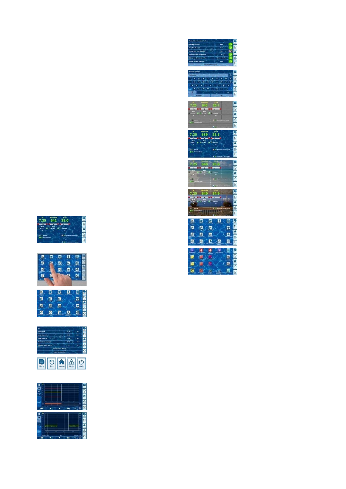
6
•
resolution 7" (18cm) colour TFT
Overview
6 Overview
6.1 PoolManager®
PoolManager® is a highly advanced measuring, controlling, and dosing
system for swimming pools.
6.2 Maintenance program
You can select from among various maintenance programs in the
PoolManager® family for your swimming pool:
• PoolManager® Chlorine (Cl)
(measurement and control of redox potential)
• PoolManager® Bromine (Br)
(Measurement and control of redox potential)
• PoolManager® Oxygen (O2)
(Automatic dosing for BayroSoft)
• PoolManager® PRO
(Measurement and control of free chlorine/bromine)
6.3 Overview of features
6.3.1 Display and operation
Great emphasis was placed on easy-to-follow, simple, and intuitive
operation while developing PoolManager®. The screen's design is also
presented in a modern and attractive manner.
The following is an overview of the significant features and concepts in
the graphic interface.
Large, high-
graphics display
• Attractive 16:10 wide format
• Wide VGA resolution (800x400)
• 65536 colours
• Energy-saving LED backlight
Simple, intuitive touchscreen operation
• Robust touchscreen with supplemental full
design overlay
• Every touch is confirmed with a signal tone
Icon menu
• Up to 20 high quality icons
• Faster and easier access to all functions
and parameters
• Additional text for each icon in order to
ensure clarity
Standard menu
• Uniform set-up on all standard menus
• Uniform operation throughout
Hotkeys
• 5 hotkeys for menu navigation and for
important basic functions that are regularly
needed (e.g. help function)
Measurement graph
• Max record length of 1 year
• Max resolution 1 min
• Display of 1 or 2 measured variables
• Display of all important alarm statuses
Mode menu
• Called up using special hotkey
• Various system functions turned on and off
quickly and easily
Numerous menu languages available
• Extensive support for special international
characters and complete character sets
(e.g. Cyrillic and Greek)
Individualisation
• Selectable menu style
• Selectable background image
• Selectable button style
6.3.2 Measuring and control
• pH and redox measurement via single-rod measuring cells (glass
electrodes)
• chlorine/bromine measurement via open potentiostatic
measurement (3-electrode system)
• Temperature measurement in the measurement chamber
(PT1000 sensor)
• 2 additional temperature inputs for additional functions (PT1000,
KTY83, or KTY16-6 sensors)
• Proportional control for all control modules
• Minimum dosing output provides for additional interval portion, i.e.
for reliable attainment of the setpoint.
• All important control parameters are individually programmable for
each control module (setpoint, alarm threshold, proportional
range, dead zone (pH), cycle time, minimum dosage, dosage
monitoring)
• Continuous display of current dosage
• Implementation of all measured variables via high resolution 10-bit
A/D converter.
• 1- or 2-point calibration for pH
• 1-point calibration for mV(redox) and temperature
User Manual PoolManager® 9
Page 10
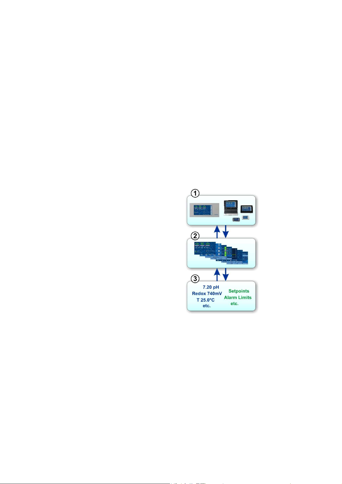
6
played by
a Web browser. There is a
browser running locally on the
unit, while
additional browsers running on
variety of devices on
the local network or on the
Internet that can access
The Web server delivers
requested menu pages to all
The data server manages and
data
,
meters) and
makes it available to the Web
Overview
6.3.3 Safety functions
Extensive monitoring and alarm functions
• Upper and lower measured value alarms
• Flow monitoring
• Level warnings and level alarms (canister level)
• Dosage monitoring
(Monitoring for when setpoint is approached)
• Battery alarm (buffer battery for the real-time clock)
• Start delay after turning on PoolManager® or after turning
circulation back on
• Automatic blocking of dosage in critical alarm states and during
start delay
• Alarm signalisation via
• Screen display
• Acoustic alarm (deactivatable)
• Alarm relay
• Continuous monitoring of correct program operation and
automatic reset in the event of an error.
6.3.4 Add-on functions
Extensive supplemental functions
• 4 universal switch outputs
Flexible control of water attractions and other applications:
• Free name selection
• Freely programmable timers
• Potential link with other inputs and outputs
• Potential link with external switches or push buttons
• Filter pump
Flexible control of the filter pump:
• 3 potential operating modes for variable filter pumps (energy-
saving mode, normal filter mode, increased output)
• Freely programmable timers
• Freely configurable dosage block
• Potential link with external switches
• Triggering via relay switching outputs or
• Power output 0/4-20mA (optional)
• Flockmatic pump
Flockmatic pump control:
• Freely programmable timers
• Configurable dosage
• Heating
Flexible control of pool heating:
• Potential link with external switch
• Potential combination with solar heating (solar priority)
• Potential block via one input
• Solar heating
Flexible control of solar heating:
• Potential link with external switch
• Potential combination with pool heating (solar priority)
• Potential block via an input
• Salt electrolysis
Flexible control of a suitable salt electrolysis system:
• Actual dosage for chlorine implemented into a
• control pulse for a salt electrolysis system
• Trigger via a relay switching output (pulse width) or power
outlet 0/4-20mA (option)
• Eco mode
Flexible control of switching between normal mode and eco mode
(e.g. circulation via overflow channel in normal mode, and/or via
floor drain in eco mode):
• Freely programmable timers
• Triggering via relay switching outputs
• Potential link with external switches or push buttons
6.3.5 Remote access from the local network or the
Internet
PoolManager's® graphical user interface is based entirely on the most
recent standard Internet (Web) technologies.
For that reason, it is also called a WebGUI:
• Web stands for Internet technologies
• GUI stands for graphical user interface
1 Web browser
The user interface is dis
PoolManager®
simultaneously there are
the widest
PoolManager® .
2 Web server
connected Web browsers.
3 Data server
stores all PoolManager®
(measured values, system status
configuration para
server.
PoolManager's® WebGUi facilitates complete and entirely transparent
remote access from a local network (TCP/IP, Ethernet) or from the
Internet. Transparent remote access means that the user interface
looks exactly like it does on the PoolManager® and is operated
identically.
Certain restrictions in remote access are required only for security
reasons.
Remote access can be realised with any mobile device or PC that is
connected to PoolManager® via a network or the Internet and that runs
a standard browser. This prerequisite is fulfilled from the start by an
ever-growing number of modern systems.
User Manual PoolManager® 10
Page 11
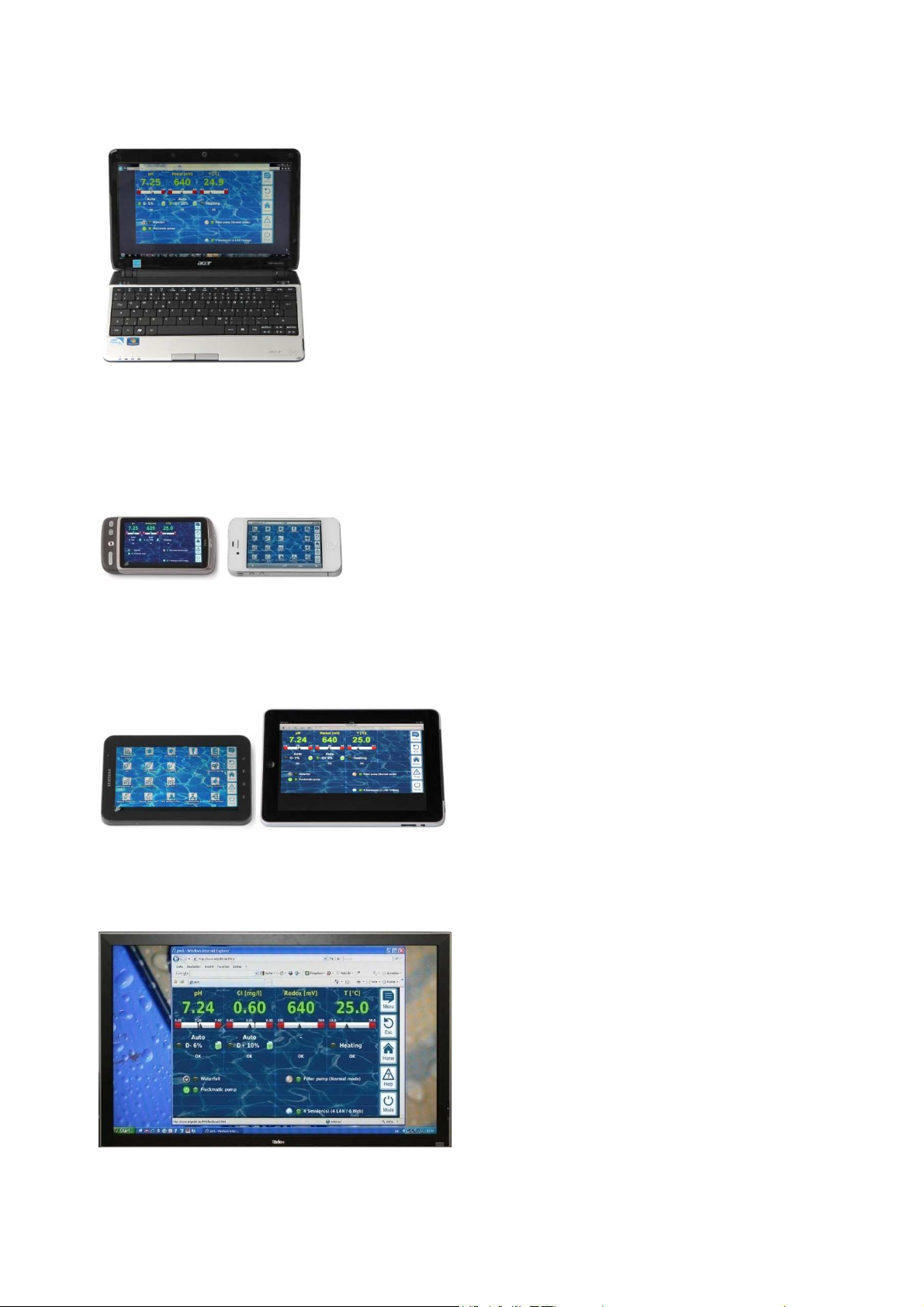
6
Overview
Suitable devices and systems for remote access
All types of PCs, such as:
• Desktop PCs, notebooks, netbooks
• Home / media centre PCs
• PCs with the Microsoft Windows ® operating system
• Apple iMac ® or MacBook ® PCs
• PCs with the Linux operation system
Smartphones, such as:
• Apple iPhone ®
• Smartphones with the Google Android ® operating system
• Smartphones with the Windows Phone 7 ® operating system
• BlackBerry ® smartphones
Building automation
Building management systems (BMS) and touch panels for living
areas can be used for remote access to PoolManager® if they have a
standard modern browser.
6.3.6 Interfaces
Measurement inputs:
• pH
• 3x temperature (PT1000 or KTY83 sensor)
Depending on casing model:
• CI/Br (potentiostatic 3-electrode system)
• Redox potential
Switching inputs:
• Flow switch (measurement water circuit), optional pressure switch
(circulation circuit)
• 2 level inputs for pH and disinfection
• 4 additional switching inputs for additional functions
Relay outputs:
• 3 dosage relays (pH minus, pH plus, disinfection)
• Alarm relay
• 4 relays (OUT1...OUT4) for supplemental functions
Every single relay output can be individually configured as a 230VAC
output or zero-potential switch.
Communication interfaces:
• Ethernet LAN (RJ45)
• Internal USB interface for memory sticks
(also used for software updates)
• CAN bus for external feature box (in development)
Optional plug-in modules (up to 3)
• 4x power output 0/4-20mA
• RS-485 communication interface for integration in building
management systems (as potential supplement to Web interface)
Tablet PCs, such as:
• Apple iPad ®
• Tablet PCs with the Google Android ® operating system (e.g.
Samsu8ng Galaxy Tab ®)
Web-compatible TV devices
(or TV devices that can be used as a PC screen)
User Manual PoolManager® 11
Page 12
7
All activities described in Part B may only be performed
User
, you can
set the corresponding IP address or URL as a favourite
quick and
For a detailed description, please refer to the
In order to use the full scope of functions for remote
, the browser being used has
, JavaScript has to
In this login window, the accessing device's keyboard
(e.g. PC keyboard or screen keyboard on a
and password,
Remote access
Part B: Function description
Required user qualification:
TRAINED USER
by trained users as defined in the Chapter
7 Remote access
PoolManager® offers comprehensive and comfortable opportunities for
remote access from a local network or from the Internet.
7.1 Prerequisites
In order to make use of the opportunities, PoolManager® first has to be
connected with a network. Then remote access has to be configured.
The required steps are described in Part C and have to be performed
by an IT specialist.
There you will find all required information for remote access to
PoolManager®.
Additionally, remote access has to be released for one or multiple
users in user management. Username and password are assigned to
the corresponding users in doing so.
See User Management.
7.2 Remote access to the local network
For remote access from the local network, you generally require
PoolManager's® network (IP) address. That could be, for example,
192.168.1.99.
7.2.1 Step by step
1. For remote access from the local network, first start the browser
2. Enter PoolManager's® IP address into the browser's address
7.3 Remote access from the Internet
For remote access from the Internet, you generally need a URL. That
could be, for example, http:// myPoolManager.dtdns.net.
7.3.1 Step by step
1. For remote access from the Internet, first start the browser on a
2. Enter PoolManager's® URL into the browser's address bar.
Qualification.
on a PC or on another mobile or stationary device on the same
network as PoolManager®.
bar. For some browsers, you'll have to enter http:// at the
beginning. Other browsers supplement it automatically.
http://192.168.1.99 (example)
PC or on another mobile or stationary device that is connected
to the Internet..
For some browsers, you'll have to enter http:// at the beginning.
Other browsers supplement it automatically:
http://myPoolManager.dtdns.net (example)
TIP
Setting up a favourite
In order to simplify access to PoolManager
®
in the browser and give it an appropriate name.
This makes remote access to PoolManager®
easy via the browser's favourites list.
documentation in the corresponding browser.
Info
HTML support
access to PoolManager
to support the current HTML 5 standard.
®
Info
JavaScript
For remote access to PoolManager
be activated in the browser being used.
®
This is normal operating procedure.
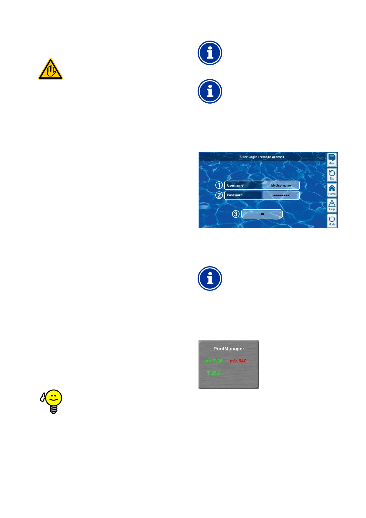
7.4 User login in remote access
When connecting to PoolManager® via remote access, a login window
first appears in which you have to authenticate yourself by entering a
valid username and the correct password.
1 Enter the username for remote access
2 Enter the password for the username entered
3 OK will confirm the entries and, after successful
authentication, start PoolManager's® user interface.
INFO
Entry via device keyboard
smartphone) is used to enter username
not the PoolManager's® screen keyboard.
7.5 Quick info
PoolManager® provides a compact info field (Quick info) with the most
important information:
The following information is shown:
• PoolManager's® device name
• Current measured value
• Text colour on measured values:
green Everything OK
red There is at least one alarm
Pressing and/or clicking on the quick info field starts normal remote
access on the corresponding device.
User Manual PoolManager® 12
Page 13
8
you can have the quick info of all relevant
This means you'll have the most important information
If, for example, there is a device showing an alarm (red
access the device with one
Display and operation - Graphical user interface
7.5.1 Calling up quick info
To call up quick info, the normal address for remote access (IP
address or URL) is attached along with the following suffix:
/cgi-bin/webgui.fcgi?infoframe=0
Thus, a complete URL would be, for example
http://myPoolManager.dtdns.net/cgi-bin/webgui.fcgi?infoframe=0
This URL is relatively complicated, but it can easily be stored in the
browser as a favourite.
TIP
Multiple devices at a glance
If you are a specialist handling multiple PoolManager
units,
devices displayed jointly on one webpage.
from all devices in one place.
text), then you can directly
click.
8 Display and operation - Graphical user
interface
Display and operation are realised on a large TFT colour display with
touchscreen. The function shown can be executed with the simple tap
of a finger on the corresponding area on the screen. Each tap on the
touchscreen is confirmed with a signal tone.
To the right of the display, there are 5 "hotkeys" for important standard
functions. The hotkey functions are also confirmed with a simple finger
tap and confirmed with a signal tone.
Menu (main menu)
Direct jump to main menu (icon menu)
Esc (escape)
Back to previous menu level
Home (home view)
Direct jump to home view
Help (help)
Display help text for the current menu
Mode (mode menu)
Direct jump into mode menu for turning on various functions
quickly and simply
8.1 Important menus
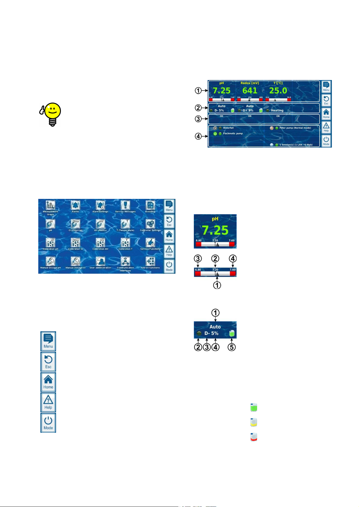
8.1.1 Home view
Home view is the standard view. It can usually be seen on the screen
and provides an overview of all important data and operating statuses.
Home view can called up at any time using the home hotkey.
®
1 Measured value shown with graphic measured value scale
2 Operating status and dosage status
3 Alarms
4 Supplemental functions
The areas 1, 2, and 3 mutually relate to a measurement or control
module, such as pH, redox, chlorine, or temperature.
1 Measured value shown with graphic measured value scale
Colour of measured value display:
green Normal operation, everything OK
‘yellow Dosage blocked (missing flow
signal and/or start delay)
2 Operating status and dosage status
red Alarm, dosage blocked!
1 Display for current measured value
2 Setpint (numeral value or mark)
3 Lower alarm threshold
4 Upper alarm threshold
1 Operating mode and/or operating status
2 LED indicates whether the dosage pump
is currently running
3 Dosage equipment
D- Decrease in measured value
D+ Increase in measured value
4 Current dosing output as %
Example: 10% means that the dosage
pump is turned on for 10% of the
available time. It will then run,
for example, for 6s
if the dosage cycle is set to 60s.
5 Fill level in the corresponding barrel:
Sufficient volume available
Limited residual volume available
The barrel is empty and has to be
replaced
User Manual PoolManager® 13
Page 14
8
Graphical user interface
Measurement, control, and dosage run
Dosage is blocked because there is no flow signal present
Dosage is blocked by a level alarm
Dosage is blocked because start delay is running
O2 (BayroSoft) only:
corresponding field for temperature measurement shows the
operating state for heating and/or solar heating if these supplemental
Active alarm for the corresponding module displayed and/or 'OK'
In the supplemental functions area in the home view, the most
important information for all current active supplemental functions is
shown. The content of this area is adjusted automatically such that all
unctions can be seen (max. of 8).
LED displays whether the supplemental function is currently
Name of the supplemental function and, if
No touch operation in home view
In order to avoid accidental erroneous commands,
home view does not react to taps on the touchscreen.
To configure settings or to move to other menus, first
use the hotkey to call up the main menu.
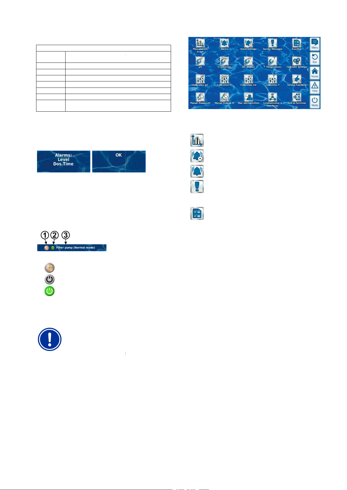
The main menu can be called up at any time using the menu hotkey. It
facilitates direct access to all important system functions.
Every function is represented by an icon with
(The icons shown depend on the corresponding device type).
Measurement Graph
Display of graphic measurement progression
verview
Display and acknowledgement of alarms
Settings for alarms and their
essages
Display and acknowledgement of service information
(e.g. notification when electrode replacement
Display of important events and incidents
Display and operation -
Operating mode and/or operating status
Auto
Manual Manual dosage is running
Off Control is turned off
Alarm Dosage is blocked by an alarm
Flow
Level
Delay
Dosage PoolManager®
in automatic mode
Automatic dosage is running
The
functions are being used
3 Alarms
displayed if there are no alarms.
4 Add-on functions
active supplemental f
supplemental text
Alarm O
Alarm Settings
Service M
signalisation
needed)
Eventlog
1 Symbol for current operating mode
Timer operation
Function turned off
Function turned on
2
turned on
3
information on current operating status
NOTE
8.1.2 Main menu (icon menu)
applicable, further
User Manual PoolManager®
14
Page 15
8
Graphical user interface
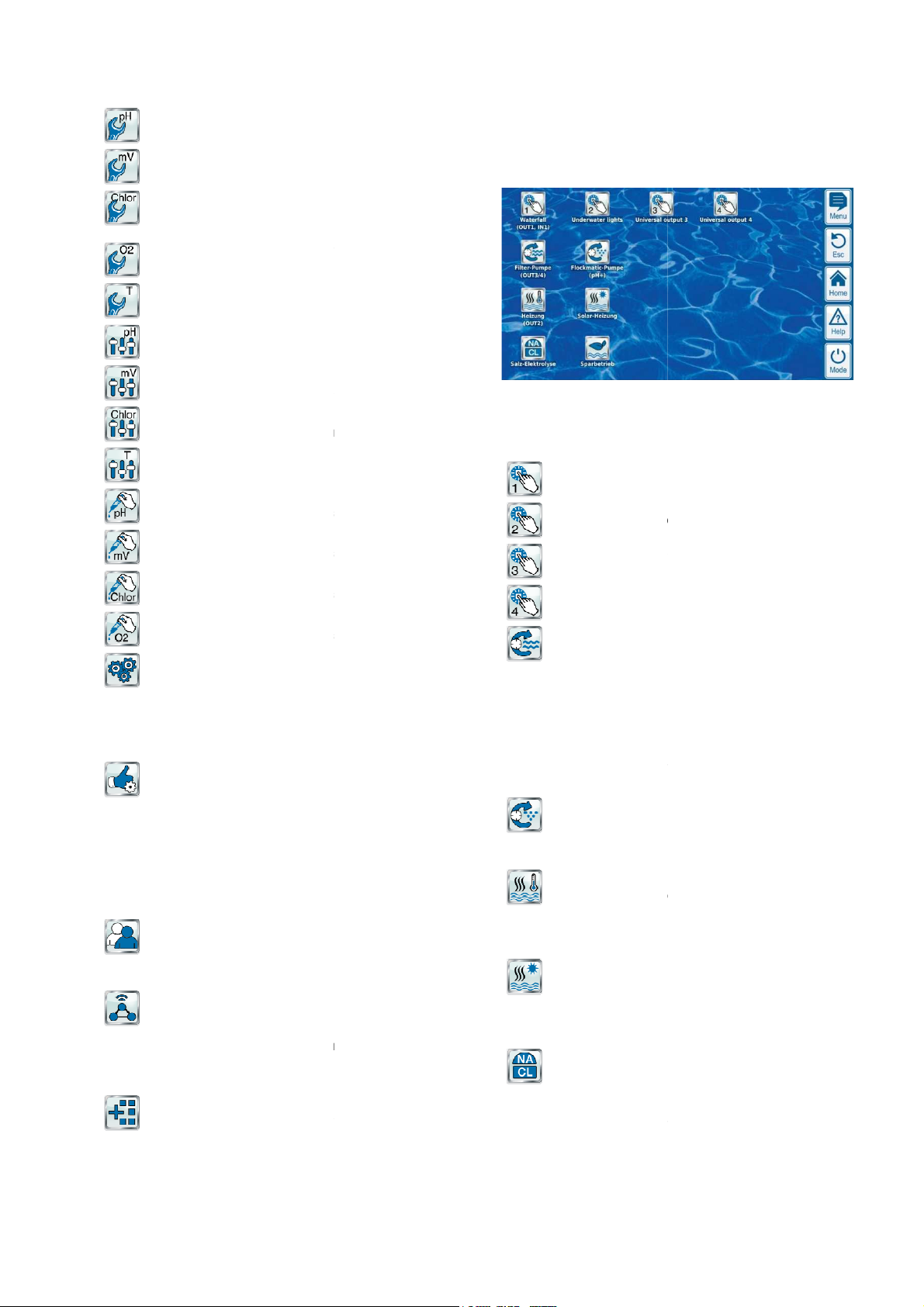
Settings for pH measurement and control
Settings for mV (redox) measurement and control
Cl (chlorine) / Br (bromine)
O2 (BayroSoft)
Settings for O2 (BayroSoft) automatic dosage
Settings for temperature measurement
pH measurement base calibration
mV (redox) measurement base calibration
Cl (chlorine) / Br (bromine)
measurement base calibration
Temperature measurement base calibration
Manually controlled addition of pH minus (or pH plus)
Manually controlled addition of chlorine/bromine
Manual Dosing Cl (chlorine) / Br (bromine)
Manually controlled addition of chlorine/bromine
O2 (BayroSoft)
Manually controlled addition of O2 (BayroSoft)
interface
Special functions (trained specialists only):
Configuration of dosage pumps
Configuration of device type
Configuration of all user data, access data, and
access rights for controlling the device and for remote
nterfaces
Data import and export (measured value graph,
Network (IP) configuration
Configuration of all further interfaces
up icon menus for supplemental functions
menu (icon menu)
functions menu is called
facilitates access to supplemental
Each supplemental function is represented by an icon with
witch output 1, 2, 3, 4
Flexible control of water attractions and other
Free name selection
Freely programmable timers
Potential link with other
Potential link with external
push button
Flexible control of the filter pump:
3 potential operating modes for variable filter pumps
saving mode, normal filter mode, increased
Freely programmable timers
Freely configurable dosage block
Potential link with external switches
Trigger via a relay switching outputs or power outlet
Flockmatic pump control:
Freely programmable timers
dosage
Flexible control of pool heating:
Potential link with external switch
Potential combination with solar heating (solar priority)
Potential block via one input
Flexible control of solar seating:
Potential link with external
Potential combination with pool heating (solar priority)
Potential block via an input
Flexible control of a suitable salt electrolysis system:
Application of the current dosage output for chlorine in
a control pulse for a salt
Trigger via a relay switching output (pulse width) or
20mA (option)
Display and operation -
Configuration pH
Configuration mV (redox)
Configuration
Settings for chlorine/bromine
measurement and control
Configuration
Configuration Temperature
Calibration pH
Calibration mV (redox)
Calibration
Chlorine/bromine
Calibration Temperature
Manual Dosing pH
Manual Dosing mV (redox)
Manual Dosing
Device Ssettings
• Basic device settings
• Menu language
• individualisation of user
• Date & time
•
Energy saving mode
Service Functions
• Pool volume
•
• Set default parameters
• Software update
• First start-up
• Measurement settings
•
User Administration
access
Communication & I
•
etc.)
•
• E-mail configuration
•
Add-on functions
Call-
8.1.3 Add-on functions
The Add-on
supplemental text.
S
•
applications:
•
•
•
•
switches or
Filter pump
•
(energyoutput)
•
•
•
•
0/4-20mA (option)
Flockmatic pump
•
•
Configurable
Heating
•
•
•
Solar heating
•
•
•
Salt electrolysis
•
•
power outlet 0/4-
up from the main menu. It
functions.
inputs and outputs
s
switch
electrolysis system
User Manual PoolManager®
15
Page 16
8
Graphical user interface
Flexible control of toggling between normal mode and eco
mode (e.g. circulation via overflow gutter in normal mode,
drain in eco mode):
Triggering via relay switching outputs
switches or
called up at any time using the mode hotkey.
ctions on and off and to set the
operating mode quickly and simply. Each function is shown on a line.
(Potential operating modes dependent upon the
operating mode can also be
Buttons for turning a function on and off quickly
The function is turned on.
the button turns the function off.
The function is turned off.
on.
Joint button for turning off ALL functions shown in the mode
The function is definitely turned off, (regardless of the
The function is automatically turned on and off
the operating mode set. 'Button on'
does NOT necessarily lead to the function being
Use button for turning on and off directly
In order to use the buttons for turning on and off
directly, set the function's operating mode to
on.
Further menus (standard menus)
Most menus, by far, consist of multiple standard recurring elements,
which can be combined with each other in a menu as desired. That is
why they are referred to as standard menus.
u consists of a max. of 8 lines
The first line always contains the menu overview.
In general, there are buttons and text fields in all menus. Buttons are
subtle 3D effect. Text fields do not have the 3D effect.
You can actuate buttons by lightly tapping on the touchscreen, thereby
triggering the underlying function. Text fields, however, only display
information and cannot be actuated.
on a parameter name will make a help text for that parameter
Tapping on a parameter value will open an entry screen and the
respective parameter can be configured.
The various standard elements are described in the followi
Numerical parameters
A numerical parameter is a numerical value. The numerical value can
be configured (configuration parameters). However, there are also
numeric parameters that are displayed only and cannot be configured,
Calls up the parameter's help text
Parameter value (button or text field)
If the parameter is configurable, then the parameter value will
be shown as a button. That will call up an entry screen in
which the value can be configured.
Display and operation -
Eco mode
and/or via floor
• Freely programmable timers
•
• Potential link with external
8.1.4 Mode menu
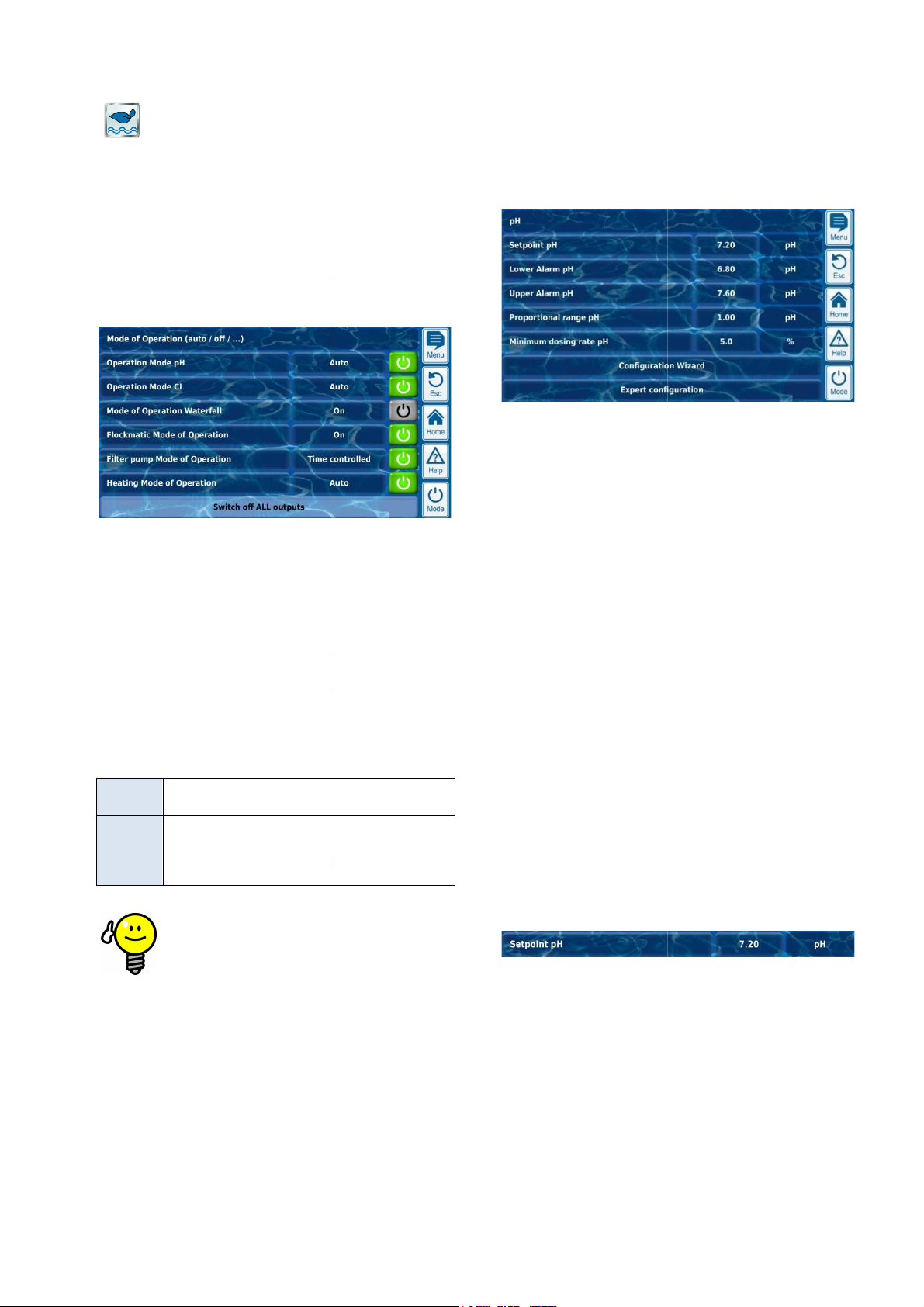
The mode menu can be
It makes it possible to turn system fun
1 Description of the various functions
2 Configured operating mode
corresponding function). The
changed here.
3
Green button
Touching
Gray button
Touching the button turns the function
4
menu.
Button function
Button
off
Button
on
operating mode set)
depending on
push buttons
8.2
8.2.1 Basic concepts
Max. 8 lines
Each men
standard elements).
Menu overview
Buttons and text fields
shown with a
Help function
Tapping
appear.
Parameter configuration
8.2.2
(Menu title and max. 7
ng sections.
turned on immediately.
TIP
e.g. measured values.
'on.'
1 Parameter name (button)
2
3 Physical unit (text field)
User Manual PoolManager®
1
2 3
16
Page 17
8
Display and operation - Graphical user interface
8.2.2.1 Entry screen
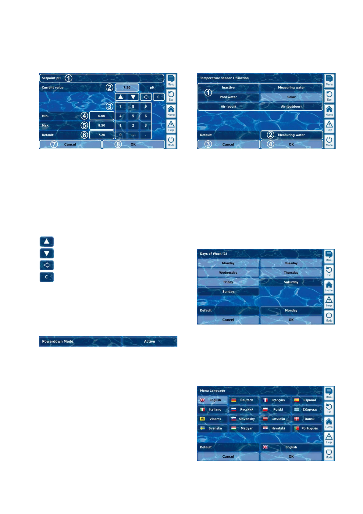
There is one uniform entry screen for all numerical parameters, in
which values can be configured.
1 Parameter name
2 Display of current (entry) value
3 Number block for entering the value
4 Minimum potential setting
5 Maximum potential setting
6 Button for resetting to the default value
7 Cancel will close the entry screen.
The value will remain unchanged.
8 OK will apply the configured value and save it
permanently.
Incremental increase and/or decrease of the configured
value.
The increment is set to be sensible for each parameter.
8.2.3.1 Entry screen
There is one uniform entry screen for all selection parameters and with
which values can be configured.
1 Display of all selection options.
Tap on the desired setting to activate it.
2 Button for resetting to the default value
3 Cancel will close the entry screen.
The value will remain unchanged.
4 OK will apply the configured value and save it
permanently.
There are also selection parameters for which multiple selections are
possible; such as multiple weekdays on which a certain process
should be launched.
Delete the last character
Delete the entire value
8.2.3 Selection parameters
For selection parameters, one of multiple settings can be selected,
such as active or inactive. The selection can be configured
(configuration parameters). However, there are also selection
parameters that can only be displayed, but not configured, such as
system statuses
1 2
1 Parameter name (button)
Calls up the parameter's help text
2 Parameter value (button or text field)
If the parameter is configurable, then the parameter value will
be shown as a button. That will call up an entry screen in
which the value can be configured.
In this case, each selection option can be activated and deactivated by
tapping on it.
For several selection parameters, a symbol is shown for each
selection option in addition to the text, such as a flag to select the
menu language.
User Manual PoolManager® 17
Page 18
8
Once you start entering a text, the current text will be
If you set the language menu to Russian or Greek, then
on the screen keyboard will be
Display and operation - Graphical user interface
8.2.4 Text parameter
A text parameter represents a text that you can enter, e.g. a name for
the device or for a function.
1 2
1 Parameter name (button)
Calls up the parameter's help text
2 Text (button)
Calls up an entry screen in which the text can be entered.
8.2.4.1 Entry screen
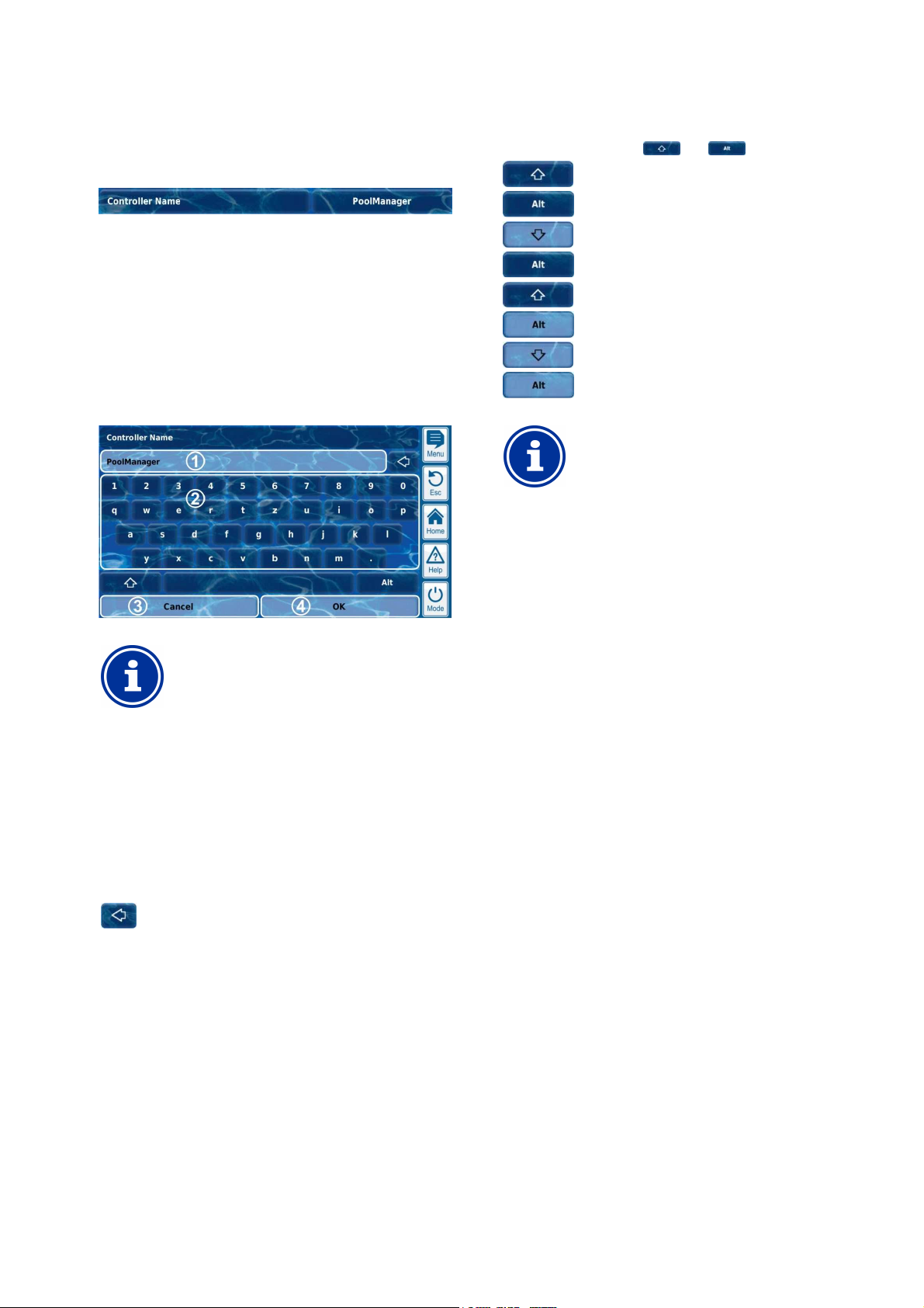
There is a uniform entry screen with a screen keyboard for all text
parameters in which the desired text can be entered.
There are a total of four different keyboard layouts available that can
be switched using the keys and as follows:
Standard keyboard layout 1:
Lower case letters and numbers
Standard keyboard layout 2:
Upper case letters and standard special characters
Alternative keyboard layout 1:
International special characters (lower case letters)
and numbers
Alternative keyboard layout 2:
International special characters (upper case letters)
and numbers
INFO
International keyboard layouts
the characters available
automatically adjusted accordingly.
INFO
Deleting the current text
automatically deleted.
1 Display of current (entry) text
2 Keyboard area for text entry
3 Cancel will close the entry screen.
The text will remain unchanged.
4 OK will apply the text entered and save it
permanently.
Delete the last character
User Manual PoolManager® 18
Page 19
8
time
clock is set to the configured time by pressing the OK
Display and operation - Graphical user interface
8.2.5 Time parameters
Time parameters are used to enter and display a time. For example:
specific time for a waterfall feature to run.
1 2
1 Parameter name (button)
Calls up the parameter's help text
2 Time (button)
Calls up the entry screen for time.
8.2.5.1 Entry screen
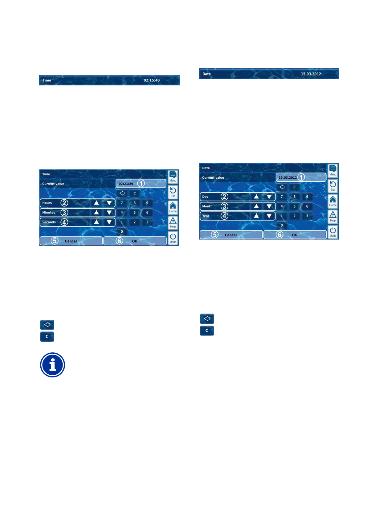
There is one uniform entry screen for all time parameters in which time
can be configured.
8.2.6 Date parameter
Date parameters are used to enter and display a date.
1 Parameter name (button)
Calls up the parameter's help text
2 Date (button)
Calls up the entry screen for date.
8.2.6.1 Entry screen
There is one uniform entry screen for all date parameters, in which the
date can be configured.
1 2
1 Display of current (entry) value
2 Incremental increase or decrease in hours
3 Incremental increase or decrease in minutes
4 Incremental increase or decrease in seconds
5 Cancel will close the entry screen.
The value will remain unchanged.
6
OK will apply the configured value and save it
permanently.
Delete the last number
Delete the entire time
INFO
Configure system time
When setting the system time, the internal real-
button.
1 Display of current (entry) value
2 Incremental increase or decrease by day
3 Incremental increase or decrease by month
4 Incremental increase or decrease by year
5 Cancel will close the entry screen.
The value will remain unchanged.
6
OK will apply the configured value and save it
permanently.
Delete the last number
Delete the entire date
User Manual PoolManager® 19
Page 20
8
Unauthorised access possible from using known
Access codes facilitate access to critical areas on the
to dangerous
Configure individualised access codes. Under no
circumstances should the preconfigured standard
Ensure that all access codes are known and available
as needed, even after longer periods of time. The
access codes are absolutely necessary for numerous
In order to protect the confidentiality of an access code,
A network (IP) address always consists of 4 number
blocks separated from each other with a dot. Each one
of the 4 number blocks can have a value in the range of
Display and operation - Graphical user interface
8.2.7 Access code
There are various access codes for menu access.
1 2
1 Parameter name (button)
Calls up the parameter's help text
2 Access code (button)
Calls up the entry screen for the access code.
HAZARD!
access codes
system. Unauthorised access can lead
configurations.
Potential consequence: Death or the gravest
degree of injury, heavy material damage.
•
access codes be used.
• Keep access codes strictly confidential.
IMPORTANT NOTICE!
Availability of access codes
8.2.7.1 Entry screen
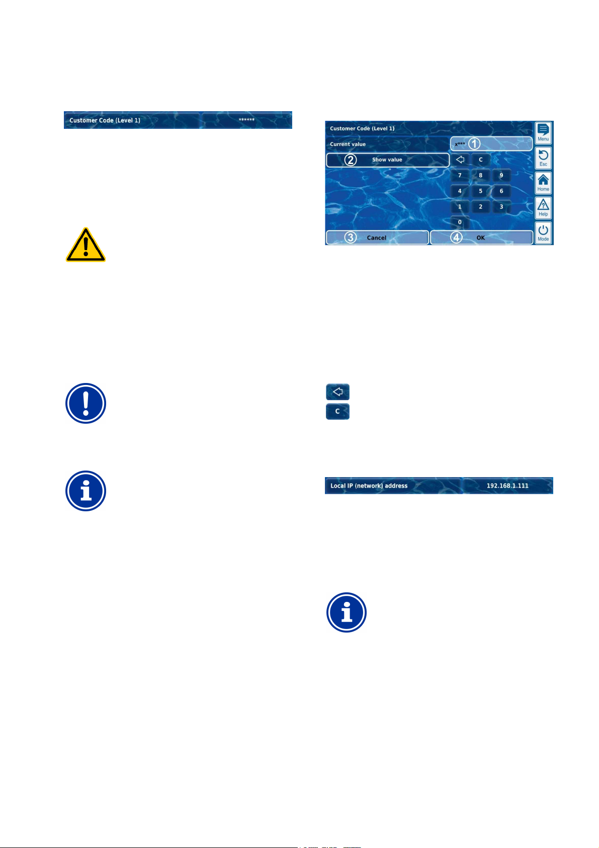
There is one uniform entry screen for configuring the desired access
code.
1 Display of a screen for the access code.
x stands for a number that has already been entered.
* stands for a number yet to be entered.
2 Pressing this button will show the actual access code
instead of the mask. Pressing it again switches back to the
mask.
3 Cancel will close the entry screen.
The value will remain unchanged.
4 OK will apply the configured value and save it
permanently.
Delete the last number
Delete the entire access code
8.2.8 Network (IP) addresses
functions and settings!
INFO
Screen display
the configured value; it is masked.
Various network addresses are entered into network configuration (IP
addresses, IP = Internet protocol).
1 2
1 Parameter name (button)
Calls up the parameter's help text
2 IP address (button)
Calls up the entry screen for the network (IP) address.
INFO
IP addresses
0...255, such as 192.168.10.8.
User Manual PoolManager® 20
Page 21
8
up for a message is optional. There
up, and
up is only
For example, if you acknowledged an alarm message,
Display and operation - Graphical user interface
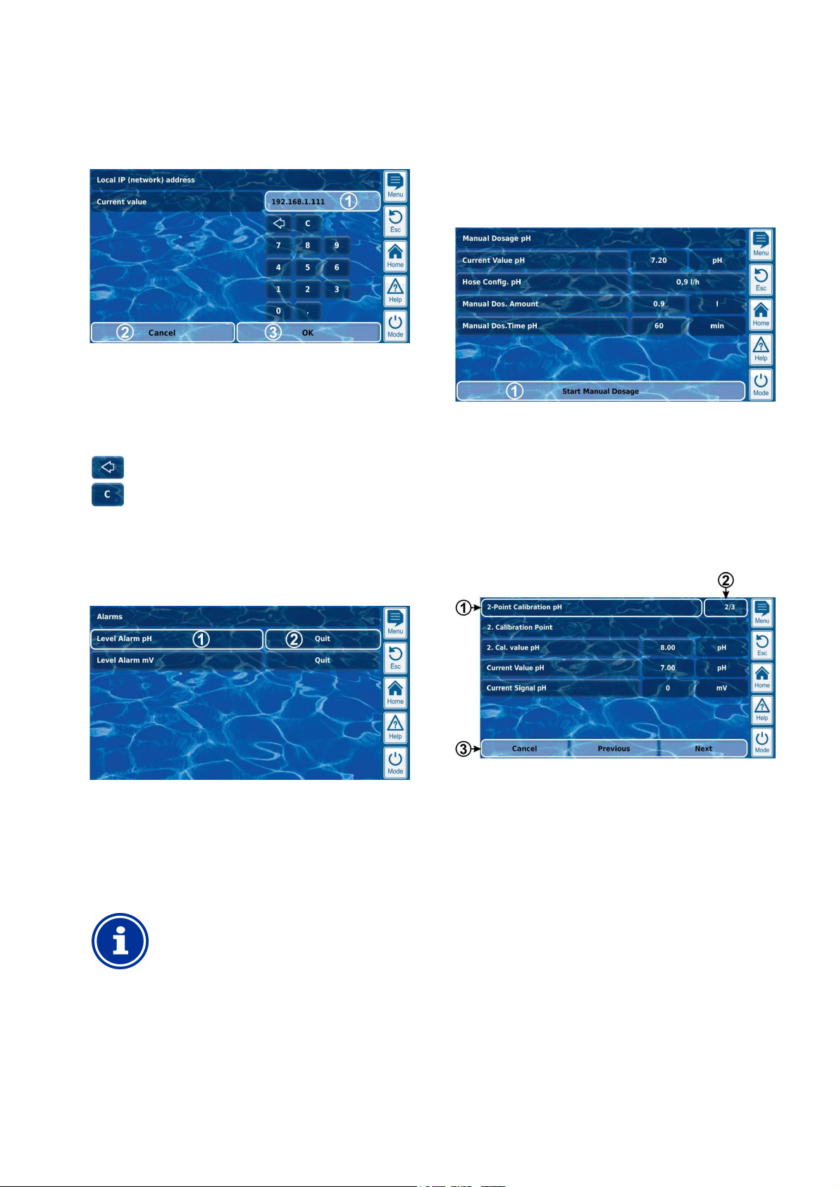
8.2.8.1 Entry screen
There is one uniform entry screen for all network (IP) addresses in
which time can be configured.
1 Display of current (entry) value
2 Cancel will close the entry screen.
The value will remain unchanged.
3
OK will apply the configured value and save it
permanently.
Delete the last number
8.2.10 Menu functions
In some menus, one or multiple menu functions are offered in the
bottom line.
Each menu function is represented by a button. Pressing the button
calls up the corresponding function.
Example: Function for starting manual dosing:
1 Menu function (button)
Calls up the corresponding function
Delete the entire network (IP) address
8.2.9 Messages
Various messages are displayed within the menus.
One typical example would be alarm messages.
The general format is unified for all messages and appears as follows:
1 Message text (button)
Calls up the message's help text
2 Function call-up (button)
Calls up a function that is assigned to the message, such as
acknowledging an alarm message.
INFO
Optional function call-up
The function callare also messages without function callmessages for which the function calldisplayed under certain circumstances.
8.2.11 Menu sequences
There are several functions that are realised via menu sequences, i.e.
via a series of menus that are run through one after another step-bystep.
Example: Calibration
1 Name of menu sequence (text field)
2 Menu no. within the menu sequence (text field)
Example: 2/3 means that the current menu is the second of a
total of three within the menu sequence.
3 Navigation buttons (buttons)
Buttons for navigating within the menu sequence (calling up
the next menu and/or the previous menu) and for cancelling
the menu sequence.
then the corresponding button will disappear.
User Manual PoolManager® 21
Page 22
8
The integrated help function is the easiest way to
certain
menu, parameter, or function. One press of key is
That is why it is recommended to use the help function
There is a great deal of informational text indicating
ving
Cancel the process if you are unable to exclude all
Display and operation - Graphical user interface
8.3 Help
Help text is available for each menu and each parameter.
TIP
Active use of the help function
receive further contextual information on a
sufficient.
actively and intensively.
Calling up the help function:
For menus
Pressing the help hotkey
For parameters
Tapping on the parameter name in a standard menu,
and/or
pressing the help hotkey in the entry screen of a
parameter
8.4 Informational text
During menu navigation, informational text is shown in many areas
that, for example, provide you with information on a function or on
potential hazards.
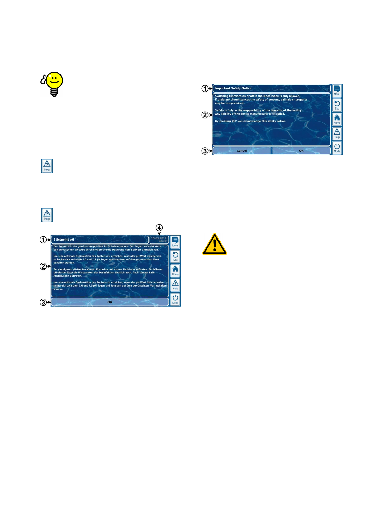
1 Title (text field)
2 Information text (text field)
3 Functions (buttons)
Pressing a function button will close the informational text.
Most informational text is confirmed with OK. For some
informational text, especially safety information, you have
the option to continue a process by pressing OK or to cancel
it.
HAZARD!
Non-compliance with informational text
1 Name of the parameter or menu that the help text refers to
(text field)
2 Help text (text field)
3 OK button (button)
Closes the help text.
4 Display of the current system time (text field)
All help menus show the current system time and the system
date.
hazards and their avoidance. Not obser
informational text may lead to hazards.
Potential consequence: Death or the gravest
degree of injury, heavy material damage.
• Read all informational text carefully.
•
potential hazards.
User Manual PoolManager® 22
Page 23
8
Graphical user interface
The user interface provides numerous opportunities for
individualisation. The various individualisation options can be found in
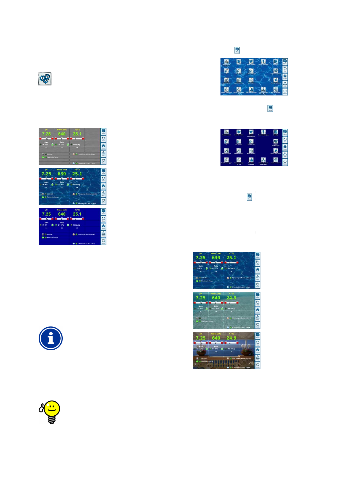
There are several attractive menu styles to choose from: Men
provide consistent and harmonious presentation of all PoolManager
Metallic style
Transparent style
(with selectable
background image)
Blue style
Note: The menu styles available may change and further styles may
device settings
offers particularly attractive display
Buttons and other menu elements are designed in a partially
transparent manner. Thus, a freely selectable background image can
that shines through the semi
up in transparent style
up takes a bit longer when using
because the extensive transparency calculations
require a great deal of computing power.
This is only noticeable when using the PoolManager
device directly. In remote access, display is realised on
the access device and therefore does not require the
computing resources.
Turning off the background image
If you would like to ensure menu change occurs as
ble, then you can change to style other
transparent style
attractive display options, then there is the following
option for optimising menu toggling:
transparent
with its
Toggle into the main menu by pressing the menu
Press the menu hotkey
background image temporarily and replaces it with a
colour background.
colour background provides for faster menu
toggling. You can reactivate the background image
later by toggling to the main menu and pressing the
again there.
It is particularly sensible to use this function if you want
ive configurations in the menus.
Background image
There are various background images available for
is also possible to upload one's own background images to
Note: The background images shown are intended as examples only.
setting in the
all background images currently available.
There are several icon styles to chose from: Icon style determines the
visualisation of icons in the main menu and in the
again. This deactivates the
Display and operation -
8.5 individualisation
the following menu:
Device Settings
8.5.1 Menu style
menus in the visualisation style chosen.
hotkey .
u styles
®
mono-
The mono-
menu hotkey
to make extens
be added. The menu style setting in the
you with all styles currently available:
8.5.1.1 Transparent style
The transparent style
be used in transparent style
menu elements in all menus.
INFO
Menu set-
Menu setstyle
PoolManager's®
TIP
quickly as possi
than transparent style.
If you would like to use
menu provides
possibilities.
-transparent
8.5.2
transparent style. It
PoolManager®.
Cool Water
Ocean
Sea View
®
The background image
device settings menu shows you
8.5.3 Icon style
add-on functions
icon menu.
User Manual PoolManager®
23
Page 24
9
Icon style 1
Icon style 2
Note: The icon styles available may change and further styles may be
device settings
internally saves all relevant measured values, alarm
statuses, operations for turning on and off, and important parameter
settings throughout the time frame of one entire year.
or the time frame of one month, a complete minute
is available. For prior months, the data volume is reduced to one
After one year has passed, the oldest data in the database are
measured value graph can be called up at any time as follows:
Stored data can be graphically displayed on the device display at any
time. Remote access to the measured value graph is also possible
(prerequisite: The browser must support HTML 5).
The following display variations can be selected:
Display of a measured variable with alarm thresholds and
Joint display of two measured variables without alarm thresholds
h flow status and/or flow alarm.
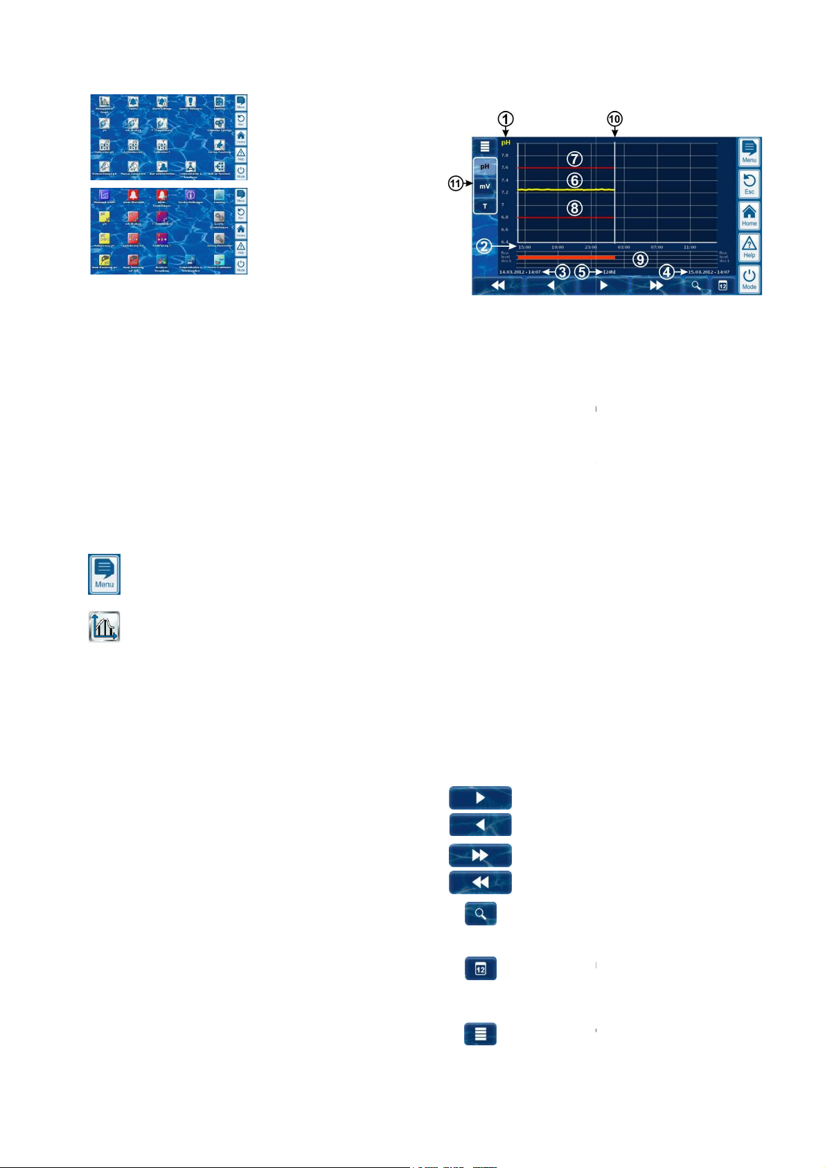
The following figure provides an overview of the
Scale for the measured variable shown (e.g. pH)
Time scale with times
Start date and time for the
currently displayed (date
End date and time for the
currently displayed (date and time on the right edge)
Time range currently displayed
[1h] / [4h] / [12h] / [24h] / [1 week]
Measured value curve
Top alarm threshold
Bottom alarm threshold
Alarm status (flow / level / dosage alarm)
An alarm is indicated by a red bar in the respective
Current point in time (= End of
Selection keys for showing one or two measured
Pressing a key activates or deactivates display of the
respective measured variable.
The measured variables currently displayed have a
light background.
A maximum of 2 measured variables can be activated
(it may be necessary to deactivate a measured
le first before another can be activated)
Slow scroll forward and/or backward along the time
axis by one half screen width, i.e. for example, by 12
hours if the screen displays 24 hours.
Quick scroll forward and/or backward along the time
by one full screen width, i.e. for example, by 24
hours if the screen displays 24 hours.
opens a selection menu for the time
frame being displayed:
1h / 4h / 12h / 24h / 1 week
Opens entry screen for a date.
ing the date and confirming, the
graph jumps directly to the date
Opens the configuration menu for the
graph
Measured value graph
added. The icon style setting in the
all icon styles currently available.
9 Measured value graph
9.1 Overview
PoolManager®
F
dataset per 15 minutes.
overwritten with current data.
The
menu shows you
-by-minute dataset
measurement graph:
1
2
3
4
5
6
7
8
9
measurement graph
and time on the left edge)
measurement graph
Menu hotkey
Measuremente graph
without restriction
•
complete alarm status.
•
and only wit
time frame.
10
11
variables
variab
axis
Zoom function -
Go to date After enter
measurement
indicated.
Menu measurement
measurement graph)
User Manual PoolManager®
24
Page 25
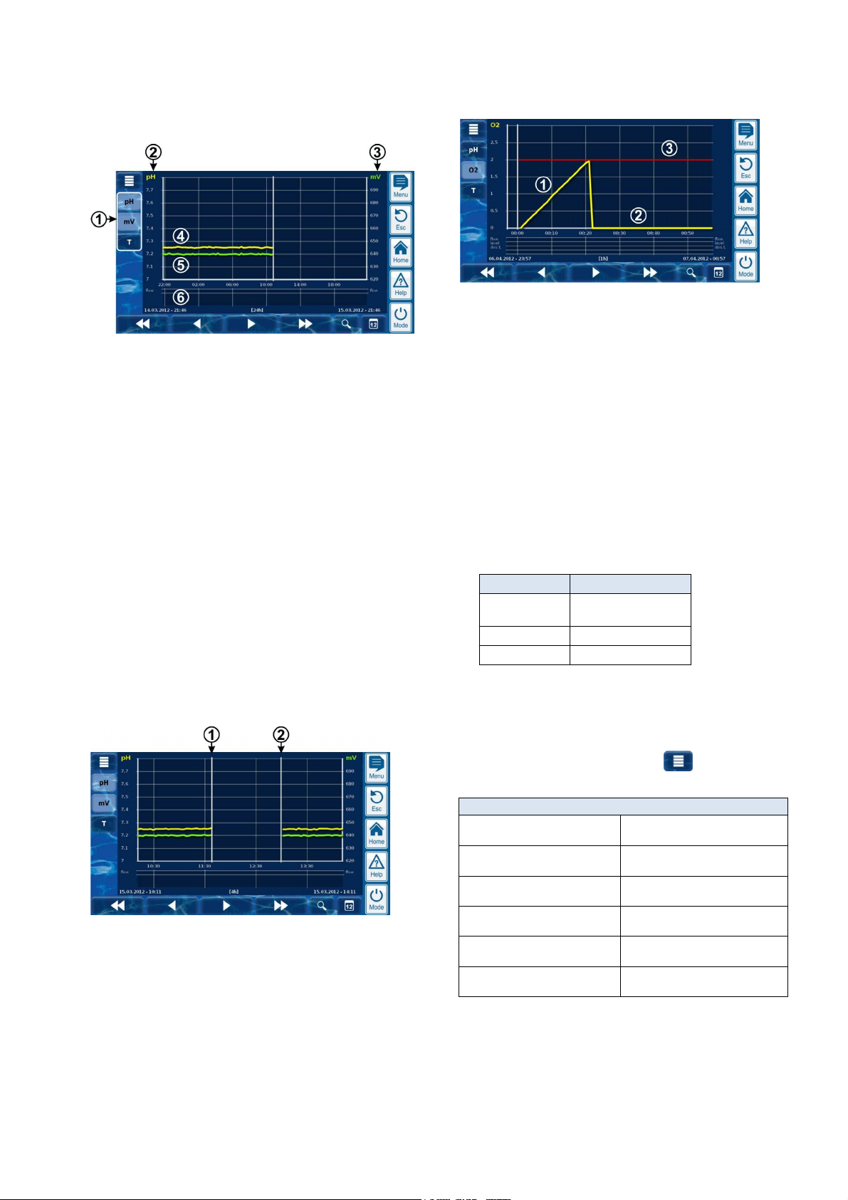
9
Measured value graph
Measurement graph with mutual display of two measured
variables
(pH and mV (redox)):
1 Selection keys for showing one or two measured variables
Pressing a key activates or deactivates display of the
respective measured variable.
The measured variables currently displayed have a light
background.
A maximum of 2 measured variables can be activated (it
may be necessary to deactivate a measured variable first
before another can be activated)
2 Scale for the first measured variable shown (e.g. pH)
3 Scale for the second measured variable shown (e.g. mV)
4 Measured value curve for the first measured variable
(e.g. pH)
5 Measured value curve for the second measured variable
(e.g. mV)
6 Alarm status (flow only)
No alarm and/or flow alarm is indicated with a red bar
in the corresponding time frame.
Measurement graph with break
(PoolManager® was turned off):
1 Point in time turned off
2 Point in time turned on
The device was turned off between point in time 1 and point in time 2.
That is why there are no measured values shown for that range.
Measured value graph (BayroSoft):
1 During O2 (BayroSoft) dosing, the current dosage volume
is displayed in litres. The measured value curve climbs
from 0 to the total dosage volume. In this example, that
number is 2 litres.
2 The measured value curve shows 0 litres for times at
which no dosage is applied.
3 For better orientation, the programmed basic dosage
volume is shown.
9.2 Notes on Measurement graph:
The value range displayed (measured value scale) is set automatically
in order to ensure optimal display of the corresponding situation. The
value range can also be set manually as needed. However, we
recommend using automatic scaling.
• The following alarm statuses are indicated in the measurement
graph.
Alarm Designation
No flow and/or
flow alarm
Level alarm Level
Dosing alarm Dos.
Flow
• Alarms are displayed for as long as they are active. It does not
matter whether they were acknowledged or not.
9.3 Configuration
The configuration measurement graph menu is called up from the
measurement graph using the menu button .
The following table shows the menu's set-up:
Menu configuration measurement graph
Configuration measurement
graph pH
Configuration measurement
graph mV
Configuration measurement
graph Cl
Configuration measurement
graph T
Configuration measurement
graph O2
Export measurement graph See section
Call-up configuration for the
pH measurement graph
Call-up configuration for the
mV (redox) measurement graph
Call-up configuration for the
Chlorine (Cl) measurement graph
Call-up configuration for the
T (temperature) measurement graph
Call-up configuration for the
O2 (BayroSoft) measurement graph
measurement export
User Manual PoolManager® 25
Page 26
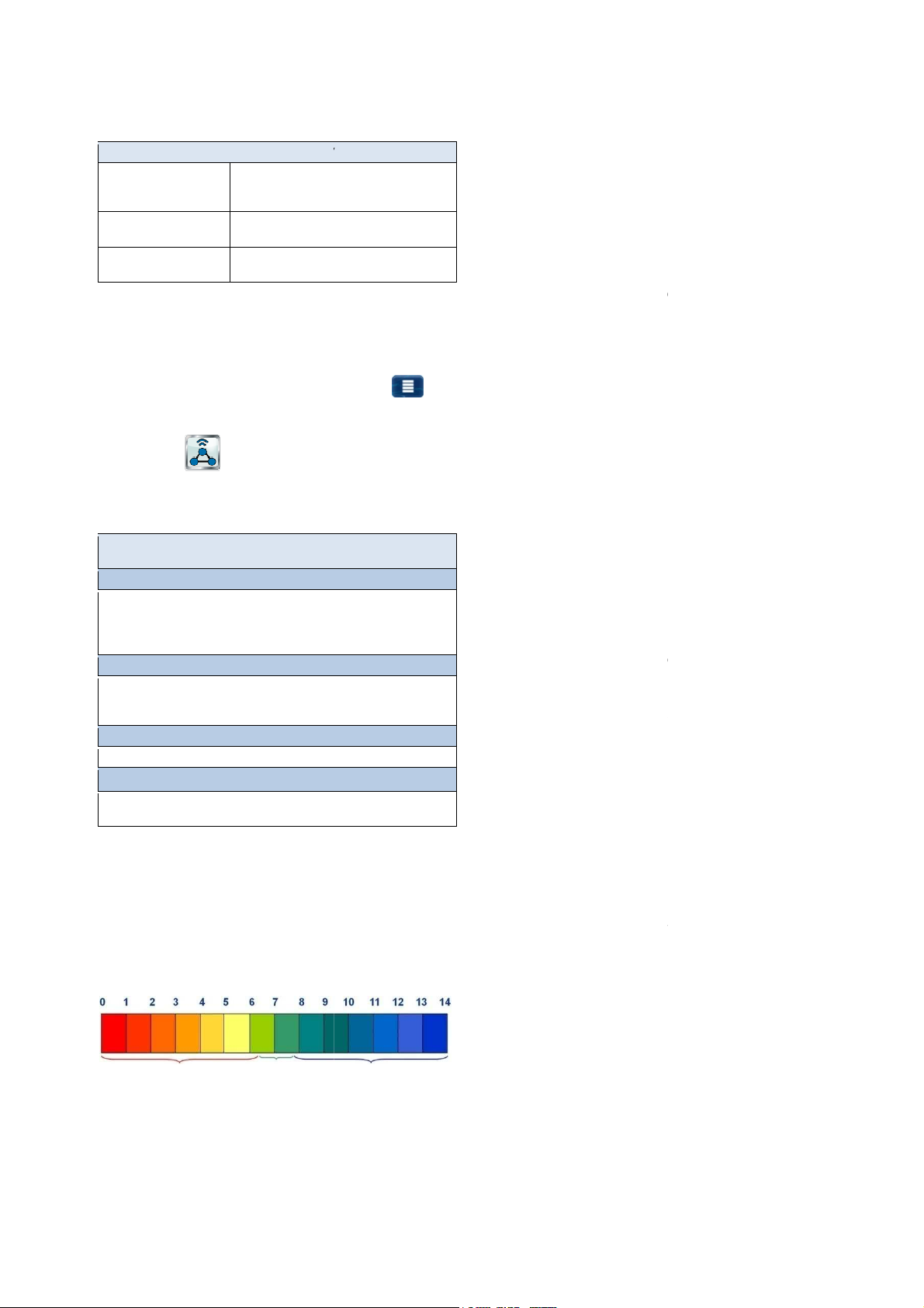
10
graph pH / mV / Cl / T / O2
Automatic or manual scaling for the display
measurement
recommend always using automatic scaling.
Minimum value of the measured
Maximum value of the measured value scale
provides various options for
be called up at any time as follows:
graph using the menu button
ommunication & interfaces,
graphs can be downloaded from
and saved locally on the remote PC in PDF format. The
ering the start and end date.
graphs can be saved locally to a USB memory stick in
graphs is made by entering the
measurement
graph
Activation and configuration of regular automatic transmission of saved
most important function is continuous measurement
and automatic correction of pH value and disinfection of pool water.
always ensures optimal water quality.
he water is in a neutral, acidic, or
basic range. The pH scale usually ranges from pH 0 to pH 14.
The basic prerequisite for optimal water quality in a pH value in the
Potential consequences of a pH value that is too low (acidic):
Expulsion of carbonate hardness (pH value fluctuations)
Potential consequences of a pH value that is too
Reduction in disinfection effectiveness (for chlorine and bromine)
Tendency for calcium deposits
continuously measures the current pH value in the pool
and compares the measured value with the desired pH value, which is
If there is a deviation, then PoolManager
pump in order to quickly and precisely
to match the setpoint by adding pH minus (pH reducer) and/or pH plus
Dosage direction pH minus (pH
Depending on the water quality and other general conditions, the pH
value increases in most swimming pool a
order to counteract that rise, pH minus (pH
case, one speaks of the dosage direction pH minus (pH
Dosage direction pH plus (pH+)
Depending on the water quality and other general conditions, the p
value decreases in some swimming pool applications as time passes.
In order to counteract that rise, pH plus (pH
case, one speaks of the dosage direction pH plus (pH+).
dosage directions with each other. In
pH control triggers two dosage pumps; one
for pH minus and one for pH plus.
Alternatively, there are three water disinfection variations available for
with active chlorine
(Measurement and control of redox potential)
Disinfection with active bromine
(Measurement and control of redox potential)
Disinfection with active oxygen
(Automated dosage with temperature compensation)
Free chlorine/bromine
potentiostatic chlorine measurement directly
records the portion of free chlorine/bromine in the pool affecting
disinfection. Hypochlorous acid HOCl influences disinfection.
Depending on pH value, only a certain portion of free chlorine is
as HOCl; please refer to the section
Water maintenance
The menus for configuring the individual
are all uniformly set-up as follows:
Menu configuration measurement
Scaling auto / hand
Display range min.
Display range max.
range, i.e. of the
(manual scaling only)
(manual scaling only)
9.4 Measurement graph export
The menu export measurement graph
exporting the measured value graph
This menu can
• From the measurement
or
• In the menu C
sub-menu data import and export
The menu provides the following functions:
Menu export measured value graph
Download measurement graphs from the device
For remote access from PC only!
In remote access, saved measurement
PoolManager®
selection of measurement graphs is made by ent
Save measurement graphs to USB stick
Saved measurement
PDF format. The selection of measurement
start and end date.
Automatic saving of measurement graph
Activation of automatic daily saving of
Automatic e-mail transmission of measurement
measurement graphs
scale. We
value scale
graphs.
Ideal pH range for pool water:
• 7.0 to 7.4
• Metal corrosion
• Attack on joints
• Skin and eye irritation
• Driving out of pool flocculant
•
high (basic):
•
• Skin and eye irritation
•
• Driving out of pool flocculant
PoolManager®
configured as a setpoint.
®
activates the pH dosage
adjust the pool water's pH value
(pH elevator).
-)
pplications as time passes. In
-reducer) is added. In this
-).
H
-elevator) is added. In this
Two-sided dosage (pH-/pH+)
It is possible to combine both
this case, PoolManager's®
10.2 Disinfection
measurement graphs to up to 3 e-mail recipients
10 Water maintenance
PoolManager's®
That is how PoolManager®
10.1 pH value
The pH value indicates whether t
neutral range.
acidic neutral
basic
User Manual PoolManager®
PoolManager®:
Disinfection
10.2.1
PoolManager® PRO
present
disinfection.
Correlation pH value and
26
Page 27
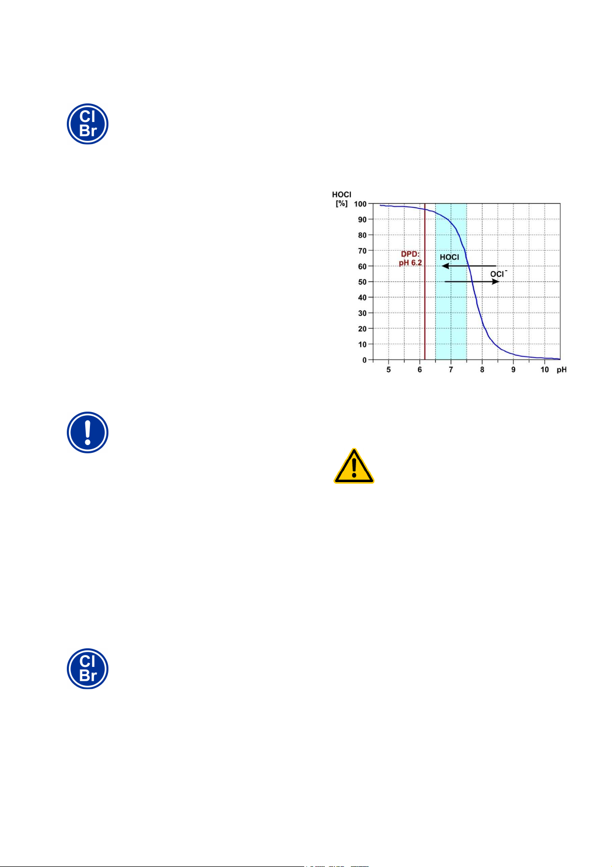
10
Cl
values can be yielded by various
pool types with the same chlorine value or bromine
value. For example, a chlorine value of 0.8 mg/l can
lead to a redox value of 720 mV in one pool, while in
on values seen in the past. Rather,
calculate the correct redox value for each individual
Cl
If disinfection is launched before the pH value is stably
to
Do not start disinfection with chlorine or bromine
until the pH value is stably in the ideal range
Water maintenance
10.2.2 Redox value
The redox value of the pool water represents electric potential that can
be measured using a corresponding electrode (redox electrode).
It is the measurement of the water's oxidation potential, and therefore
of current disinfection effectiveness.
The redox value is a sum parameter that can be influenced by
numerous substances in the pool water.
Oxidizing substances (disinfectants) raise the redox value
• Hypochlorous acid HOCl for disinfection with active chlorine
• Hypobromous acid HOBr for disinfection with active bromine
Reducing substances (contaminants) lower the redox value
• Inorganic and organic contaminants
• Chloramine, oils, carbamide, sweat, germs, bacteria, algae,
Due to these numerous influences, it is generally not possible to
determine the chlorine/bromine level in the pool directly from the redox
value measured. It is, however, possible to set the desired
chlorine/bromine value in the pool and then to calculate the associated
redox value.
(Disinfection with chlorine and bromine)
INFO
This section applies for the models PoolManager®
and PoolManager® Br only.
leaves,etc.
IMPORTANT NOTICE!
Determining the correct redox value
Widely different redox
Free chlorine measurement and the redox signal measured are not
directly dependent upon the level of free chlorine, but rather influenced
only by the hypochlorous acid, which influences disinfection. If,
however, the portion of hypochlorous acid changes due to a
fluctuating pH value, then that will necessarily lead to a fluctuating
redox value. Stable and reliable disinfection is then no longer possible.
The so-called dissociation curve shows the correlation between pH
value and the share of hypochlorous acid HOCl among all free
chlorine. At a pH of 6.5, ca. 95% of the free chlorine is present as
HOCl. At a pH of, however, that number is only 30%.
If control measurements are performed using the DPD method, then it
is important to know that the DPD measurement is always performed
at a pH value of ca. 6.2. That value is attained with an integrated pH
buffer in the DPD reagents. Thus, a DPD measurement measures all
free chlorine independently of the actual pH value in the pool.
HAZARD!
Overdosage if pH value is wrong
another pool, it can lead to a redox value of 780 mV.
• Do not rely
pool separately.
The redox value yielded for the desired chlorine/bromine value is
configured as a setpoint in PoolManager®. The control system ensures
that the redox value remains consistently on level with the configured
value.
As long as there are no significant changes in other influential
variables, the consistent redox value simultaneously provides for a
constant chlorine/bromine level in the pool, thereby ensuring reliable
disinfection.
10.2.3 Correlation pH value and disinfection
INFO
This section applies for the models PoolManager®
and PoolManager® Br only.
The basic prerequisite for reliable and stable disinfection with chlorine
and bromine is a consistent and optimally configured pH value in the
pool.
There are two significant grounds for this:
For high pH values over 7.5, the portion of free chlorine present as
hypochlorous acid (HOCL) sinks dramatically. Since, however, only
hypochlorous acid is effective for disinfection, disinfection
effectiveness reduces in the same dimension. Sufficient disinfection is
no longer ensured.
in the ideal range of 7.0 to 7.5, then it may lead
heavy overdosage of chlorine or bromine.
Potential consequence: Death or the gravest
degree of injury, heavy material damage.
•
between 7.0 and 7.5.
User Manual PoolManager® 27
Page 28
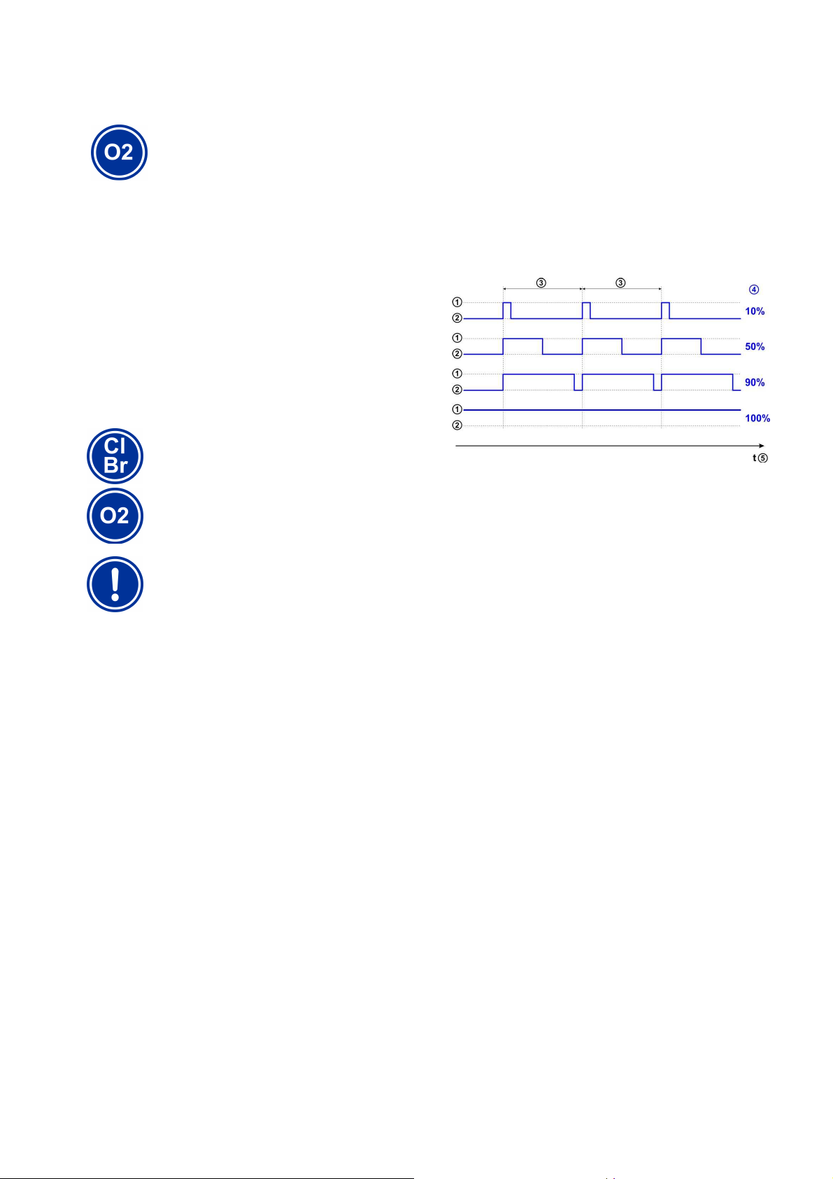
11
The information in this section on measuring and
controlling the redox value applies only for the models
controlling the pH
models, i.e. also for
Correct calibration of pH measurement and, if
applicable, redox measurement is an absolute
reliable measurement and
Please refer to the information in the section
Measurement, control, dosage
(pH value, redox value, chlorine/bromine)
10.2.4 Active oxygen (BayroSoft)
INFO
This section applies for the model PoolManager® O2
only.
For disinfection with active oxygen, an main dosage is performed
automatically once a week in order to initially raise the pool's oxygen
content to a high level, thereby yielding a strong disinfection effect.
Then additional interim dosages are performed throughout the course
of a week as needed in order to maintain the oxygen level
continuously over the requisite minimum value that ensures safe and
reliable disinfection.
The volumes for the main dosage and the interim dosages are
automatically adjusted to the average pool temperature in order to
compensate for heavier product attrition at higher temperatures. This
function is called temperature compensation.
11 Measurement, control, dosage
(pH value, redox value, chlorine/bromine)
INFO
PoolManager® Cl and PoolManager® Br.
The information for measuring and
value applies for all PoolManager®
PoolManager® O2.
IMPORTANT NOTICE!
Need for calibration
example, a dosing output of 10% means that the dosage pump runs
10% of the available time within a dosage cycle, and stands still during
90% of the time.
Example:
• The dosage cycle is set to 60 s.
• The current dosing rate is 10%.
The pump's running time will then be 10% of 60s, i.e. 6s.
The pump's off time will then be 90% of 60s, i.e. 54s.
The following figure shows cyclical turning on and off of dosage pumps
for various dosing outputs.
1 Dosage pump running (on)
2 Dosage pump not running (off)
3 Dosage cycle (for example, 60s)
4 dosing output 10% / 50% / 90% / 100%
5 Time axis
requirement for exact and
control.
Calibration.
11.1 Function
Measurement and control for the pH value, free chlorine/bromine, and
for the redox value are set-up as identically as possible.
PoolManager® continuously measures the pH value and the current
redox value in the pool and compares the current measured values
with the desired levels, which are configured as setpoints.
PoolManager® PRO continuously measures the pH value and the
concentration of free chlorine/bromine in the pool and compares the
current measured values with the desired levels, which are configured
as setpoints.
If there is a deviation between the current measured value and the
setpoint, a so-called rule deviation, then PoolManager® activates the
corresponding dosage pump (or other dosage equipment) in order to
adjust quickly and precisely.
11.2 Dosage rate
The controller continuously calculates the optimal dosing output in the
current situation. The farther the current measured value is from the
setpoint, the higher the configured dosing rate is.
Dosing rate is indicated as a percentage [%]. A dosing rate of 100%
means that the dosage pump is running continuously. The absolute
dosing rate in l/h is yielded from the pump type used and/or the
dosage hose used.
For lower dosing rates, the controller periodically turns the dosage
pump on and off within a predefined dosage cycle (e.g. 60 s). For
User Manual PoolManager® 28
Page 29
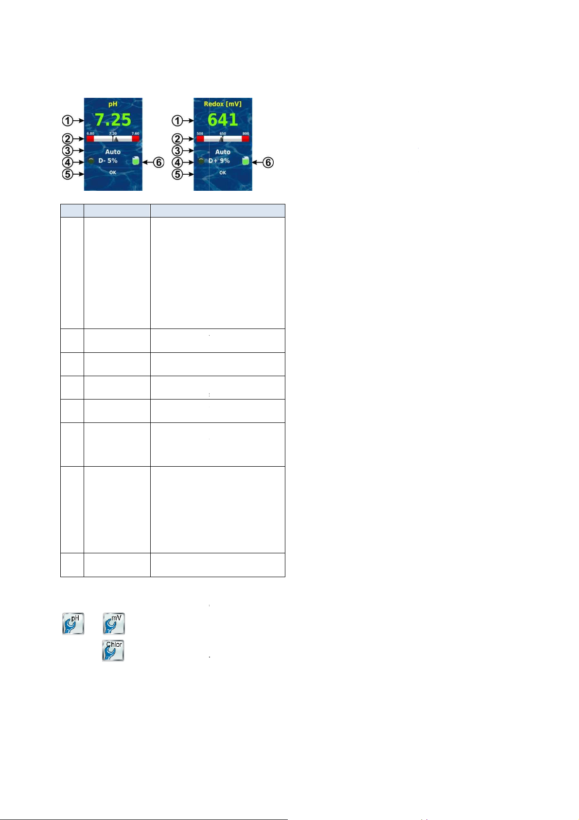
11
0.00...9.99 pH or 0…999mV
PRO:
0.00...9.99 pH or 0…9.99mg/l
Colour of measured value display:
Normal operation, everything
Dosage blocked (missing flow
start delay)
Alarm, dosage blocked!
Graphic display of current measured
value, setpoint, and alarm thresholds.
Auto / off / manual / alarm / flow / start
illuminates when the
corresponding dosage pump is running.
D+ (elevating) / D
(dosing output 50% means, for
example, that the dosage pump runs
All active alarms are shown regarding
the current module.
Alarms whose cause has already been
remediated disappear from the display,
even if they have not been
If there is no active alarm, "OK"
respective canister (red
You'll find all configuration parameters in the following menus:
PoolManager
Several of the configuration parameters are
The setpoint sets the desired optimum value of the controlled
parameter. The control system always attempts to adjust the
measured value to match the setpoint as quickly and precisely as
alarm threshold
If the measured value falls below the
will report a bottom measured value alarm.
alarm threshold
If the measured value exceeds the
op measured value alarm.
Proportional range
The control system works as a proportional control system, which
means dosing output is increased proportionally to rule deviation, i.e.
to the deviation between the current measured value and the
oint. The farther the values in the pool are from the
setpoint, the more maintenance product is dosed in order to reach the
The proportional range, abbreviated p
output proportionally to the rule deviation
between 0% (dosage pump off) and 100% (dosage pump running
(pH reducing)
The proportional range begins with the
The proportional range ends at 1.00 pH above the setpoint, i.e. at
pH 8.20 (dosing output 100%)
The centre of the proportional range is at pH 7.70
Dosage direction D+ (elevation of redox value)
The proportional range begins with the setpoint
The proportional range ends 200 mV below the setpoint, i.e. at
550 mV (dosing output 100%)
The centre of the proportional rang
Chlorine, just PoolManager
Dosage direction D+ (elevation of chlorine value)
The proportional range begins with the setpoint
The proportional range ends 0.50mg/l below the setpoint, i.e. at
0.15mg/l (dosing output 100%)
The centre of the proportional range is at 0.40mg/l
Measurement, control, dosage
(pH value, redox value, chlorine/bromine)
11.3 Display in home view
Pos. Content Notes
1 Current measured
value
2 Measured value
scale
3 Current operating
mode
4a LED symbol The LED symbol
4b Current dosing
direction
4c Current dosing
rate
5 Alarms
6 Canister symbol Fill level for the
PoolManager®
green
OK
‘yellow
signal and/or
rot
delay (x min)
0...100%
50% of the time)
acknowledged.
appears.
/ yellow / green)
11.4 Configuration parameters
pH mV (redox)
Cl (chlorine)
enhanced configuration.
- (reducing)
®
PRO only
found in the sub-menu
11.4.2 Lower
PoolManager®
11.4.3 Upper
PoolManager® will report a t
11.4.4
configured setp
setpoint quickly and precisely.
control system varies dosing
permanently).
Example 1 (pH):
• Setpoint pH 7.20
• Proportional range 1.00 pH
• Dosage direction D-
output 0%)
(dosing output 50%)
Example 2 (pH):
• Setpoint 750 mV
• Proportional range 200 mV
•
(750 mV, dosing output 0%)
(dosing output 50%)
Example 3 (
• Setpoint 0.65mg/l
• Proportional range 0.50mg/l
•
(0.65mg/l, dosing output 0%)
(dosing output 50%)
lower alarm threshold, then
upper alarm threshold, then
-range, is the range in which the
setpoint (pH 7.20, dosing
e is at 650 mV
®
PRO):
11.4.1 Setpoint
possible
User Manual PoolManager®
29
Page 30

11
for the proportional
A larger proportional range will result in a lower
range will halve
A smaller proportional range will result in a higher
range will double
The default values indicated for the proportional range
For pool volumes that are larger in relation to pump
range generally
on times on the dosage
er pool volumes in relation to pump
range generally
on times on the dosage
following cases, the proportional range should be
If the control system reacts slowly, and the setpoint
In the following cases, the proportional range
ncreased, thereby decreasing the
The control system and dosage output when near the
for marginal rule deviations, is determined
by the configured minimum dosing output. The
proportional range exerts no influences when near the
Measurement, control, dosage
(pH value, redox value, chlorine/bromine)
The following figure shows the correlation between the current
measured value and the dosing output for various configurations of the
proportional range for pH (dosage direction D-).
1 dosing output in %
2 Measured pH value
3 Configured setpoint pH 7.20
4 Proportional range 0.50 pH (pH 7.20 - 7.70)
5 Proportional range 1.00 pH (pH 7.20 - 8.20)
6 Proportional range 2.00 pH (pH 7.20 - 9.20)
7 At the end of the proportional range, dosing output reaches
100%, i.e. the dosage pump runs permanently.
INFO
Basic rules for the proportional range
The following basic rules are helpful
range:
INFO
Influence on the control system
In the
reduced, thereby increasing the dosing output:
•
is not approached or is only approached slowly
•
should be i
dosing output:
• If the control system reacts too quickly or unstably
11.4.5 Minimum dosing rate
A purely proportional control system generally has problems in actually
attaining the desired setpoint. When approaching the setpoint, the
dosing output drops even further and approaches 0%.
In order to guarantee the setpoint is reached, a minimum dosing
output is configured that is maintained until the setpoint is actually
reached.
The following figure uses the pH control system as an example to
show the progress of dosing output while accounting for the minimum
dosing rate.
dosing output.
For example, doubling the proportional
the dosing output.
1 dosing output in %
2 Measured pH value
dosing output.
For example, halving the proportional
the dosing output.
INFO
Pool volume and dosing output
3 Configured setpoint pH 7.20
4 Configured minimum dosing rate (5%)
5 Constant dosage of the minimum dosing rate
upon approaching the setpoint
6 Theoretical progression without minimum dosing rate
are orientated toward the following general conditions.:
• Assuming a pool volume of ca. 40m³
INFO
Control system output when near the setpoint
• dosing output on pumps ca. 1.5 l/h
setpoint, i.e.
dosing output, the proportional
has to be reduced.
This leads to longer switch-
setpoint.
pump, and therefore to higher dosage overall.
For small
dosing output, the proportional
has to be increased.
This leads to shorter switchpump, and therefore to lower dosage overall.
User Manual PoolManager® 30
Page 31
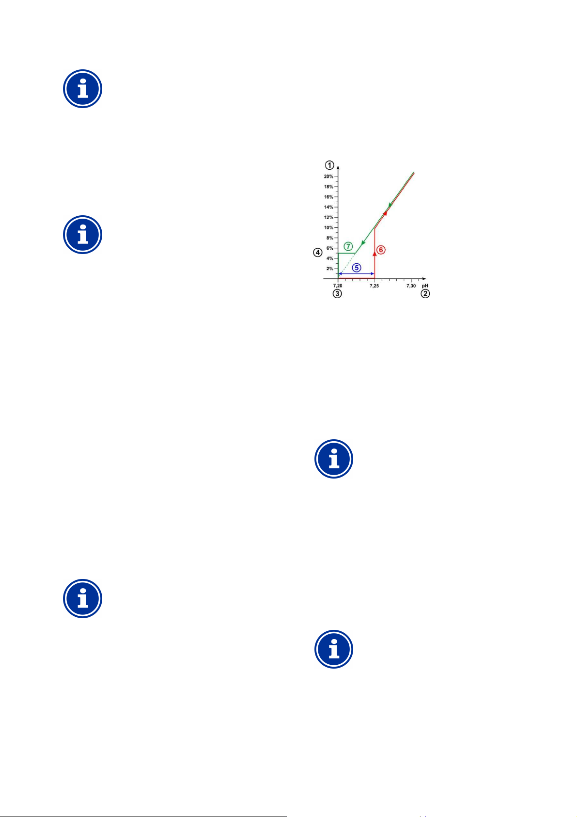
11
rate
,
the minimum dosing output generally has to be
,
the minimum dosing output generally has to be
should be increased in the
he standard setting for the
increase the preconfigured interval if
dosage alarms are repeatedly reported unfoundedly. In
general, this will only happen if the pool is reacting
extremely slowly or if there are very high downtimes, or
is case, the entire installation should be checked,
zone is 0, i.e. the
directional pH control in order to avoid
pH minus and pH plus
ndard setting for the
as whirlpools, a shorter
cycle may deliver better results under certain
circumstances as the control system can react to
Measurement, control, dosage
(pH value, redox value, chlorine/bromine)
INFO
Pool volume and dosing rate
The default values indicated for minimum dosing
are oriented toward the following general conditions:
• Assuming a pool volume ca. 40m³
• dosing output on pumps ca. 1.5 l/h
For larger pool volumes in relation to pump dosing rate
increased.
For larger pool volumes in relation to pump dosing rate
increased.
INFO
Influence on the control system
The minimum dosing rate
following cases:
• When the setpoint is not entirely attained, or
attained only very slowly
• The minimum dosing output should be decreased
in the following cases:
• When the control system exceeds the setpoint, i.e.
overdosage
11.4.6 Intelligent dosing monitoring
If the current measured value deviates from the desired setpoint, then
PoolManager® will dose maintenance product into the pool water in
order to offset the deviation. In this case, it should be expected that
the measured value approaches the setpoint.
PoolManager® checks in the indicated intervals whether the setpoint is
actually approached as expected. Additionally, PoolManager®
assesses various criteria calculated based on a large number of
circumstances. If the setpoint matching criteria are met, then the
dosing output will be continued.
If those criteria are not met, then PoolManager® will report a dosage
alarm and block continued dosage. In this case, there is presumably
either a problem or the current settings are not appropriate for the
pool. In the event of a dosage alarm, the entire system should be
inspected for potential problems.
The dosage alarm and the dosage block are ended by pressing the
corresponding button to acknowledged the dosage alarm in the alarm
overview.
You can set the interval for dosage monitoring in [min] in the menu. At
the end of each interval, a test is executed on whether the setpoint is
being approached according to the criteria.
INFO
Configuring dosing monitoring
For most applications, t
dosing monitoring interval should deliver good results.
You should only
if there is some other miscellaneous problem.
In th
especially circulation.
11.4.7 Dead zone
An activated dead zone ensures that dosage is not started for
minimum deviations from the setpoint, but rather only after the current
measured value departs from the dead zone. The dead zone is quasi
a tolerance range around the setpoint.
The following figure shows how the control system performs in the
dead zone using pH control as an example.
1 dosing output in %
2 Measured pH value
3 Configured setpoint pH 7.20
4 Minimum dosing output (5%)
5 Dead zone (0.05pH pH 7.20...7.25)
6 Dosage does not begin until the measured value departs from
the dead zone
7 When approaching the setpoint, dosage will not stop when
entering the dead zone but rather upon reaching the setpoint.
INFO
Dead zone application
The standard setting for the dead
dead zone is not active.
It is particularly recommended to activate the dead
zone for biconstant triggering of the
dosage pumps.
11.4.8 Dosing cycle
The dosing cycle is a defined, fixed time interval in which the dosage
pumps are turned on and off depending on the current dosing output.
The sum of switch-on duration and switch-off duration is always
constant and corresponds to the dosing cycle.
A graphic presentation of the dosage cycle can be found in the section
dosing output above.
INFO
Notes on configuring the dosing cycle
For most applications, the sta
dosing cycle should deliver good results.
For very small pools, such
dosing
changes more quickly.
User Manual PoolManager® 31
Page 32
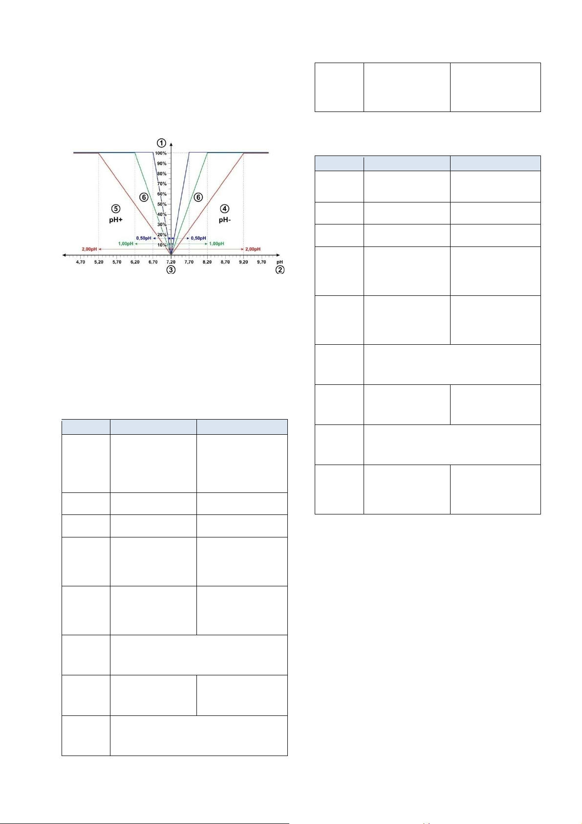
11
Measurement, control, dosage
(pH value, redox value, chlorine/bromine)
11.4.9 Dosing direction
As already described in the Water maintenance section, the pH control
system can be optionally run in a pH-reducing, pH-elevating, or bidirectional manner depending on water composition.
The following image shows an example for control system output in
the event of bi-directional dosage.
1 dosing output in %
2 Measured pH value
3 Configured setpoint pH 7.20
4 pH measured value is higher than setpoint
pH minus dosage
5 pH measured value is lower than setpoint
pH plus dosage
6 dosing rate for various proportional ranges
11.4.10 Recommended settings
The following table provides information on the recommended
parameter settings for pH and redox control.
Parameter pH Redox (mV)
Setpoint Ideal range
Lower alarm
threshold
Upper alarm
threshold
Proportional
range
Minimum
dosing rate
Intelligent
dosing
monitoring
Dead zone 0.00 pH for mono-directional
Dosing cycle The standard setting (60s) delivers good results in most
pH 7.0 ... 7.4
ca. setpoint - 0.4 pH ca. setpoint - 50 mV
ca. setpoint + 0.4 pH ca. setpoint - 50 mV
ca. 1.50 pH
for 40 m³ pool and
dosage pumps 1.5 l/h,
see section
Proportional range
ca. 4.0%
for 40 m³ pool and
dosage pumps 1.5 l/h,
see section
Minimum dosing output
The standard setting (60 min) delivers good results in most
applications and should only be changed in exceptional
cases; see section
Intelligent dosage monitoring
control,
0.10 pH for bi-directional
control
applications.
For very small pools, e.g. whirlpools, it may be sensible to
reduce to 30s.
The right redox setpoint has
to be defined individually for
each pool; please refer to the
section
Determining the
redox (mV) setpoint
ca. 150 mV
for 40 m³ pool and
dosage pumps 1.5 l/h,
see section
Proportional range
ca. 4.0%
for 40 m³ pool and
dosage pumps 1.5 l/h,
see section
Minimum dosing output
0mV
Dosing
direction
Depending on
water composition:
D- (pH-reducing),
D+ (pH-elevating) or bidirectional (D+/D-)
D+
(Increase in redox value by
dosing chlorine or bromine)
11.4.11 Recommended settings for PoolManager® PRO
The following table provides information on the recommended
parameter settings for pH and redox control.
Parameter pH Chlorine (Cl) / Bromine (Br)
Setpoint Ideal range
Lower alarm
threshold
Upper alarm
threshold
Proportional
range
Minimum
dosing output
Intelligent
dosing
monitoring
Dead zone 0.00 pH for mono-direction
Dosing cycle The standard setting (60s) delivers good results in most
Dosing
direction
pH 7.0 ... 7.4
ca. setpoint - 0.4 pH ca. setpoint - 0.25mg/l
ca. setpoint + 0.4 pH ca. setpoint + 0.25 mg/l
ca. 1.50 pH
for 40 m³ pool and
dosage pumps 1.5 l/h,
see section
Proportional range
ca. 4.0%
for 40 m³ pool and
dosage pumps 1.5 l/h,
see section
Minimum dosing output
The standard setting (60 min) delivers good results in most
applications and should only be changed in exceptional
cases; see section
Intelligent dosage monitoring
control,
0.10 pH for bi-direction
control
applications.
For very small pools, e.g. whirlpools, it may be sensible to
reduce to 30s.
Depending on
water composition:
D- (pH-reducing),
D+ (pH-elevating) or bidirectional (D+/D-)
Depending on application
region
(Germany
ca. = 50 mg/l
for 40 m³ pool and
dosage pumps 1.5 l/h,
see section
Proportional range
ca. 4.0%
for 40 m³ pool and
dosage pumps 1.5 l/h,
see section
Minimum dosing output
0 mg/l
D+
(Increase in chlorine/bromine
concentration)
11.5 Configuration assistant
11.5.1 Basics
Sensible configuration of the proportional range and the minimum
dosing rate is largely dependent upon pool volume and dosage pump
output. In the end, what counts is the ratio between pool volume and
the pumps' dosing output.
The values used as the foundation for the default settings are:
• Assuming a typical pool volume of 40 m3
• dosing output on standard pump 1.5 l/h
• The assumed ration between pool volume in [m³] and dosing
output in [l/h] is therefore 40 to 1.5, i.e. ca. 27.
For a larger pool volume in relation to dosing output, the control
parameters generally have to be adjusted as follows:
• Smaller proportional range ( higher dosing output)
• Higher minimum dosing rate
Accordingly, for a smaller pool volume in relation to dosing output the
control parameters generally have to be adjusted as follows:
• Larger proportional range ( lower dosing output)
• Lower minimum dosing rate
User Manual PoolManager® 32
Page 33
12
The control settings calculated with the help of the
configuration assistant generally deliver good results
but cannot guarantee optimum control quality in every
Under certain circumstances, it may be necessary to
parameters manually if problems
Erroneous calibration, or not performing calculation,
can lead to significant measurement errors, which
under certain circumstances may result in heavy
Perform careful calibration in each of the following
Calibration (basic measurement comparison)
11.5.2 Configuration assistant
There is a configuration assistant in each of the configuration menus
for pH and chlorine (Cl) and redox (mV). You only need to enter the
pool volume and the dosage pump output into the assistant. The
assistant uses that data to calculate sensible basic settings for the
control parameters, especially for the proportional range and the
minimum dosing output.
A manual correction can be indicated in order to adjust the automatic
calculation performed by the assistant:
Manual
correction Effect
0% Standard calculation, no correction
-90%...-1% Reduction of dosing rate by the indicated %-value on the
1% ...
100%
standard calculation for lightly burdened pools with low needs
for maintenance products.
Increase in dosing rate by the indicated %-value in the
standard calculation for heavily burdened pools with high
maintenance product needs.
IMPORTANT NOTICE!
Manual optimisation of control parameters
case.
optimise the control
arise.
12 Calibration (basic measurement comparison)
The basic prerequisite for exact and reliable measurement and control
is regular calibration of the measurement electrodes.
The electrodes convert the measured water parameters into an
electric measurement signal. The correlation between the value in the
pool and the electric measurement signal is not always the same and
may vary from electrode to electrode. Furthermore, it depends on
water quality and other general conditions that can change over the
course of time.
Calibration calculates the exact correlation between the measured
water parameter and the electric measurement signal. Precise
measurement can only be expected after calibration.
12.1 When is calibration necessary?
Calibration absolutely must be performed in the following situations:
• First start-up or return to service
• Water change
• Electrode replacement
• If there are relevant deviations between what the device displays
and the manually control measurements performed on a regular
basis
• After adding water supplements or after miscellaneous changes in
water quality
• In regular intervals, at least once a month
HAZARD!
Overdosage due to
missing or incorrect calibration
overdosing of pH minus or chlorine.
Potential consequence: Gravest degree of injury,
heavy material damage.
•
situations
12.2 pH calibration
There are various options for calibrating a pH electrode:
• 1-point calibration with buffer solution pH 7
• 2-point calibration with buffer solutions pH 7 and pH 9
(or other pairs, such as pH 6.80 and pH 4.65)
• 1-point calibration to the pool's pH value
(Determined with photometer or simple colour tester)
For 1-point calibration, the display value is moved one consistent
offset up or down. The electrode slope is not recalculated in 1-point
calibration. It remains unchanged.
In 2-point calibration, the electrode slope is recalculated in addition to
the offset.
User Manual PoolManager® 33
Page 34

12
Calibration (basic measurement comparison)
Precise calculation can be attained with the following
point calibration with buffer solutions pH 7 and
pH 9 in order to calculate the exact electrode slope.
point calibration to the pool's pH value
with a photometer in order to attain the best
possible between the device's display and
This calibration should be performed as close to the
setpoint as possible, i.e. the pH value in the pool
should be in the ideal range between 7.0 and 7.4
If there is no photometer avail
should be performed. A simple colour tester does not
produce reliable calibration with the requisite precision.
point calibration generally suffices for regular
recalibration (at least once a month). If there is a
tometer available, then recalibration should be
performed to the pool's pH value; otherwise with buffer
pH calibration can be found in the following menu:
point calibration pH
Calibration is a menu sequence, i.e. it goes through a series of
Calibration input (1st and 2nd calibration point)
In the input menus for the 1st and 2nd calibration point, the following
For the calibration value, enter the reference value to which calibration
When calibrating with a buffer solution, this will be the known pH value
n calibrating to the pool water's pH value, this will be the value
measured with a photometer (a simple colour tester is not suitable for
calibration as the measurement precision is not sufficient).
calculated using the parameters
from the last calibration, which are still valid. This value may deviate
from the actual value under certain circumstances. It is only displayed
to give you a certain level of orientation throughout calibration.
asured value, you can see when measurement stablises
when you, for example, place the electrode into the buffer solution.
This is the currently measured electric signal on the electrode in [mV].
see when measurement
Furthermore, you can use it to test the measurement signal for
able, then only step 1
+30
point calibration only)
point calibration, the electrode slope is also displayed in
[mV/pH] and can be edited manually. This makes it possible for you to
enter a typical value for slope, or to reset slope to its default value.
point calibration, slope cannot be entered as it is calculated
At the end of calibration, the calibration parameters generated are
point calibration, this is the newly
point calibration this is the previously entered value.
Offset is the zero point displacement calculated from calibration. It is
The pH measured value is then calculate
the current calibration. The measured value displayed should therefore
coincide with the calibration value entered.
point calibration with buffer solution (e.g. pH 7)
Block the measurement water
rode cable from the device
Unscrew the pH electrode from the measurement chamber
Rinse the pH electrode off with (distilled) water
Carefully dab the pH electrode dry using a towel (free from
Connect the electrode cable to the device
In the menu, select the function
Enter the pH value of the buffer solution as the
If necessary, enter a value for electrode slope or reset the value
Dip the pH electrode into the b
If the displayed measured value and the measurement signal
have stablised and are no longer changing in a relevant
manner, then confirm calibration by pressing
Check the calibration results displayed a
Place the pH electrode back into the measurement chamber
off valves for measurement water
TIP
pH calibration
procedure:
Basic calibration step 1
2-
Basic calibration step 2
Subsequent 1-
concordance
the photometer measurement.
Recalibration
1-
pho
solution pH 7.
12.2.1 Execution
Calibration pH
Calibration is executed as follows:
• Select 1-point calibration pH or 2-
•
menus step-by-step.
12.2.1.1
parameters are displayed:
Calibration value pH
should be performed.
of the buffer solution, such as pH 7 or pH 9.
Whe
Current value pH
This is the current measured value
Using the me
Current signal pH
pH value 6.0 6.5
Typical
measurement
signal
+60
mV
7.0 7.5 8.0 8.5
0 mV -30 mV -60 mV -90 mV
mV
Tolerance to be expected ±10%
pH Electrode slope (for 1-
For 1-
For 2exactly during calibration.
12.2.1.2 Calibration results
displayed:
Electrode slope
For 2[mV/pH]; for 1-
calculated electrode slop in
Offset
indicated in [pH].
Current value pH
d using the parameters from
12.2.1.3 Step by step
1-
1.
2. Separate the elect
3.
4.
5.
grease and fuzz).
6.
7.
8.
again.
1-point calibration pH
calibration value
(generally pH 7)
9.
to default
10.
uffer solution (e.g. pH 7) and stir
it carefully
11.
12.
Next.
nd close calibration by
pressing Ready.
13.
14. Open the shut-
You can also use the measurement signal to
has stablised.
plausibility.
User Manual PoolManager®
34
Page 35

12
asic measurement comparison)
point calibration with buffer solution (e.g. pH 9 and pH 7)
electrode cable from the device
Unscrew the pH electrode from the measurement chamber
Rinse the pH electrode off with (distilled) water
Carefully dab the pH electrode dry using a towel (free from
Connect the electrode cable to the device
point calibration pH
Enter the pH value of the 1st buffer solution as the
Dip the pH electrode into the 1st buffer solution
e displayed and the measurement signal
have stablised and are no longer changing in a relevant
manner, then confirm the 1st calibration point by pressing
Remove the pH electrode from the 1st buffer solution
Rinse the pH electrode off with (distilled)
Carefully dab the pH electrode dry using a towel (free from
Enter the pH value 2. Buffer solution as the
Dip the pH electrode into the 2nd buffer solution
If the measured value displayed and the measurement signal
have stablised and are no longer changing in a relevant
manner, then confirm the 2nd calibration point by pressing
Check the calibration results displayed and close calibration by
Place the pH electrode back into the measurement chamber
off valves for the measurement water
point calibration to the pool water's pH value
Take a water sample from the measurement chamber and
calculate the pH value using a photomete
point calibration pH
Enter the pool water's pH value calculated using the photometer
If necessary, enter a value for electrode slope or reset the value
If the measured value displayed and the measurement are
stable and are no longer changing in a relevant manner, then
Check the calibration results displayed and close calibration by
uring calibration, various plausibility criteria are checked. If one of the
criteria is not met, then a corresponding error message appears and
The following criteria have to be met for successful calibration:
ated (zero point displacement) has to be in the range
of ±1.00 pH. The offset is generally close to 0 for flawless electrodes.
The electrode slope calculated must be in the range of 50.0 mV/pH to
70.0 mV/pH. For flawless electrodes, the slope is generally
point calibration, the two calibration values have to be at least
point calibration with buffer solutions pH 7 and
Calibration chlorine (Cl) /
PRO)
Calibration for free chlorine/bromine measurement is performed as 1
point calibration. The pool water's DPD measured value is entered as
a reference value. It can be calculated using a photometer.
Alternatively, a simple colour test
recommended due to the limited precision.
IMPORTANT NOTICE!
Calibration near to setpoint
For reliable and precise calibration of chlorine/bromine
measurement, this has to be performed as close to the
desired setpoint as
First bring the chlorine/bromine concentration in the
pool to the desired value (=setpoint) via manual
dosage or manual addition.
Check the value via DPD measurement
Do not perform calibration until the value in the
pool is close to the desired
tolerance ca. setpoint ±10%)
IMPORTANT NOTICE!
Calibration for bromine
Bromine concentration and chlorine concentration can
be calculated using DPD measurement. However, the
same colour on the DPD sample yields different values
for chlorine and bromine.
If your photometer/colour tester is expressly
designed for bromine measurement, then you can
use the bromine value read directly.
If your photometer/colour tester is only designed for
chlorine measurement, then you have to multipl
the chlorine value by 2.2 in order to obtain the
correct bromine value (e.g. DPD measurement for
chlorine 1.0 mg/l
point calibration
Even if you only have to enter one calibration point,
PRO
point calibration. The second calibration point used is
the zero point from the potentiostatic measurement,
which is always nearly the same.
Chlorine/bromine calibration can be found in the following menu:
Calibration is executed as follows:
Calibration is a menu sequence, i.e. it goes through a series of
The following parameters are displayed in the calibration menu:
Enter the measured DPD value as the calibration value (calibrate
This is the current measured value calculated using the parameters
from the last calibration, which are still valid. This value may devi
from the actual value under certain circumstances. It is only displayed
to give you a certain level of orientation throughout calibration.
setpoint (permissible
y
Calibration (b
2-
1. Block the measurement water
2. Separate the
3.
4.
5.
grease and fuzz).
6.
7. In the menu, select the function 2-
8.
calibration value pH (e.g. pH 9)
9.
(e.g. pH 9) and stir carefully
10. If the measured valu
11.
12.
13.
grease and fuzz).
14.
value pH (e.g. pH 7)
15.
(e.g. pH 7) and stir carefully
16.
17.
pressing Ready.
18.
19. Open the shut-
1-
20.
(phenol red method).
21. In the menu, select the function 1-
22.
as the calibration value pH
23.
to default
24.
confirm calibration by pressing Next.
25.
pressing Ready.
12.2.2 Calibration errors
D
calibration is not executed.
The offset calcul
again.
water
2nd calibration
r
1st
12.3
(just PoolManager®
bromine (Br)
-
can be used. However, this is not
possible.
•
Next.
•
•
Next.
•
•
bromine 2.2 mg/l).
INFO
Internal 2-
PoolManager®
internally performs a precise 2-
12.3.1 Execution
Calibration Cl/Br
• Select calibration Cl
•
menus step-by-step.
12.3.1.1 Calibration input
Cal. Value Cl (DPD 1 value)
55.0 mV/pH and 60.0 mV/pH.
For 2-
0.50 pH apart. 2pH 6.80, for example, is not possible.
between
close to setpoint!).
Current Value Chlorine
User Manual PoolManager®
ate
35
Page 36

12
Calibration (basic measurement comparison)
Using the measured value, you can see whether measurement is
At the end of calibration, the calibration parameters generated are
Offset is the zero point displacement calculated from calibration. It is
sured value is then calculated using the
parameters from the current calibration. The measured value
displayed should therefore coincide with the calibration value entered.
surement chamber and
calculate the chlorine/bromine value using a photometer
Calibration Cl
Enter the pool water's DPD value calculated as the
he measurement are
stable and are no longer changing in a relevant manner, then
Check the calibration results displayed and close calibration by
plausibility criteria are checked. If one of the
criteria is not met, then a corresponding error message appears and
The following criteria have to be met for successful calibration:
Calibration must be performed for a calibrat
The offset calculated (zero point displacement) has to be in the
range of ±1.00 mg/l. The offset is generally close to 0 for flawless
The slope calculated has to be in the range of 1µA/mg/l
/mg/l. For flawless electrodes, slope is generally in the
Calibration redox (mV)
The calibration for redox measurement is performed as 1
calibration. A buffer solution with a known redox value (e.g. 465 mV) is
Redox calibration
Depending on water quality and the state of the
electrode, it can occur that the redox electrode reacts
very slowly if it is moved from the buffer solution back
into the measurement water after calibration. In
disadvantageous condi
until the measured redox value stablises again and is
displayed correctly.
During that time, reasonable configuration and launch
of redox control is not possible.
Therefore, it is recommended to only perform redox
on when necessary, such as when it is
suspected that the electrode could be defect.
In general, calibration can be omitted for the following
reasons in order to avoid potential problems with the
time it takes to function properly again:
Functioning redox e
tolerance range, such that calibration only changes the
display value by a few mV.
The absolute redox value is not of significant important.
Assigning the redox value to the chlorine value in the
pool is more important; see
redox (mV) setpoint.
Redox (mV) calibration can be found in the following menu:
Calibration is executed as follows:
point calibration mV
Calibration is a menu sequence, i.e. it goes
The following parameters are displayed in the calibration menu:
For calibration value, enter the reference value for calibration, i.e. the
redox value of the buffer solution b
This is the current measured value calculated using the parameters
from the last calibration, which are still valid. This value may deviate
from the actual value under certain circumstances. It is only disp
to give you a certain level of orientation throughout calibration.
Using the measured value, you can see when measurement has
stablised when you place the electrode into the buffer solution.
tions, it may take several hours
lectrodes generally have a tight
Determining the
sufficiently stable for reliable calibration.
12.3.1.2 Calibration results
displayed:
Offset Chlorine
indicated in [mg/l].
Current Value Chlorine
The chlorine/bromine mea
12.3.1.3 Step by step
Calibration to the measured DPD value
26. Take a water sample from the mea
(DPD1 method).
27. In the menu, select the function
28.
Cl (DPD 1 value)
29. If the measured value displayed and t
confirm calibration by pressing Next.
30.
pressing Ready.
Cal. Value
12.4
used.
TIP
calibrati
-point
12.3.2 Calibration errors
During calibration, various
calibration is not executed.
•
(DPD values) of at least 0.20 mg/l.
•
electrodes.
•
250 µA
range of 5µA/mg/l and 20µA/mg/l.
ion value
section
12.4.1 Execution
Calibration mV (Redox)
• Selection 1-
–
•
menus step-by-step.
12.4.1.1 Calibration input
Calibration mV (Redox)
Current value Redox (mV)
through a series of
eing used (e.g. 465 mV).
layed
User Manual PoolManager®
36
Page 37

12
The redox value configured for the desired
chlorine/bromine value can vary widely from pool to
Therefore, the correct redox setpoint must be
es experienced in the past are surely helpful for
evaluation. However, the redox setpoint cannot be
configured based solely on values experienced in the
past, as the correct redox setpoint in an individual case
nces in the
Depending on water quality and the state of the
the redox electrode reacts
very slowly when reinserted or when moved from the
buffer solution back into the measurement water after
calibration. In disadvantageous conditions, it may take
up to 24 hours for the measured redox value to stablise
The correct redox value cannot be read and applied as
Insert a new redox electrode into the measurement
water circuit as early as possible. Then, it will be able to
stablise even if the final chlorine/bromine value is not
Observe the redox value for at least 15 minutes. The
redox value cannot be considered to be sufficiently
no longer changes within 15 minutes,
under certain circumstances it may slowly rise up to 20
or 30 mV over the next 24 hours. Therefore, check
redox control again a few days after launching. Perform
a DPD measurement and optimise the configured
Calibration (basic measurement comparison)
12.4.1.2 Calibration results
At the end of calibration, the calibration parameters generated are
displayed:
Offset
Offset is the zero point displacement calculated from calibration. It is
indicated in [mV].
Current measured value
The redox (mV) measured value is then calculated using the
parameters from the current calibration. The measured value
displayed should therefore coincide with the calibration value entered.
12.4.1.3 Step by step
1-point calibration with buffer solution (e.g. 465 mV)
31. Block the measurement water
32. Separate the electrode cable from the device
33. Unscrew the redox electrode from the measurement chamber
34. Rinse the redox electrode off with (distilled) water
35. Carefully dab the redox electrode dry using a towel (free from
grease and fuzz)
36. Connect the electrode cable to the device again.
37. In the menu, select the function 1-point calibration Redox (mV)
38. Enter the buffer solution's redox value as the calibration value
Redox (mV), e.g. 465 mV
39. Dip the redox electrode into the buffer solution (e.g. 465 mV)
and stir it carefully
40. If the measured value displayed has stablised and is no longer
changing in a relevant manner, then confirm calibration by
pressing Next.
41. Check the calibration results displayed and close calibration by
pressing Ready.
42. Place the redox electrode back into the measurement chamber
43. Open the shut-off valves for the measurement water
12.4.2 Calibration errors
During calibration, various plausibility criteria are checked. If one of the
criteria is not met, then a corresponding error message appears and
calibration is not executed.
The following criteria have to be met for successful calibration:
• The offset calculated (zero point displacement) has to be in the
range of ±100 mV. The offset is generally close to 0 for flawless
electrodes.
IMPORTANT NOTICE!
Determining the correct redox setpoint
pool.
determined individually for each pool.
Valu
can deviate significantly from values experie
past.
12.5.1 Step by step
1. Bring the pool to the desired value via manual dosage or manual
addition of chlorine or bromine. It's best to add the requisite
volume in multiple increments and to check the value repeatedly
using DPD measurements.
2. After the desired chlorine or bromine value has been set in the
pool and checked via DDP measurement, observe the redox
value shown on the PoolManager®.
It will rise due to the addition of chlorine or bromine.
3. Wait until the displayed value has stablised. It should stop
experiencing relevant changes within 10-15 minutes.
4. The redox value shown corresponds to the previously configured
chlorine/bromine value in the pool. Thus, configure the redox
value shown as the setpoint for redox control.
5. Redox control will then maintain the redox value at the configured
setpoint, simultaneously providing for a constant chlorine/bromine
value in the pool.
IMPORTANT NOTICE!
Redox electrode stablisation
electrode, it can occur that
and be displayed correctly.
12.5 Determining the redox (mV) setpoint
Electrode calibration is not of decisive importance for redox control.
Correct determination of the redox setpoint is.
After all, redox control should provide a predefined chlorine/bromine
level. As long as water quality and other general conditions do not
change significantly, the redox value measured is directly dependent
upon the concentration of free chlorine/bromine. A change in
chlorine/bromine concentration always results in a change in the redox
potential measured. Conversely, this means that the chlorine/bromine
concentration remains constant if the control system is providing a
constant redox value. It counteracts a sinking redox value immediately
by dosing chlorine/bromine, thereby maintaining the redox value
consistently at the configured setpoint.
the setpoint until after stablisation has occurred.
Recommendations:
yet configured.
stable until the change over that time frame is max. 12 mV.
Even if the value
redox setpoint as needed.
User Manual PoolManager® 37
Page 38
13
Automatic dosage O2 (BayroSoft)
13 Automatic dosage O2 (BayroSoft)
INFO
This section applies for the model
PoolManager® O2 only.
13.1 Basic concept
Adding the optimal volume of BayroSoft into the swimming pool water
is executed in multiple automatic dosages per week. The main dosage
is performed on a specific chosen weekday, which provides for a high
BayroSoft concentration and therefore for optimal disinfection. Then
additional interim dosages are performed throughout the course of a
week as needed in order to maintain the oxygen level continuously
over the requisite minimum value that ensures safe and reliable
disinfection.
The volumes for the main dosage and the interim dosages are
automatically adjusted to the average pool temperature in order to
compensate for heavier product attrition at higher temperatures. This
function is called temperature compensation.
The recommended setting for the basic dosage volume is 0.5 litres per
10m³ of pool volume.
13.1.1 Main dosage
The main dosage is performed on a specific weekday, the main
dosage day. The volume of BayroSoft dosed on that day is based on
the programmed basic dose volume. However, depending on the
water temperature measured, the actual dose amount may be
increased by a certain factor. This mechanism is called temperature
compensation. The dose amount is corrected such that the increasing
product consumption that occurs with increasing temperature is
compensated.
The factor used to increase the programmed dose amount is yielded in
the following table:
Average temperature value from the previous week
25°C 26°C 27°C 28°C 29°C 30°C 31°C 32°C >32°C
≤24°C
Factor 1.00 1.06 1.10 1.15 1.20 1.28 1.40 1.57 1.80 2.00
No temperature compensation is performed for water temperatures
under 24°C.
For water temperatures over 32°C, double the programmed dose
amount is added.
Example:
For a programmed dose amount of 2.0 litres and water temperature at
28°C:
Main dose amount = 2.0 litres x factor of 1.20 = 2.40 litres
The main dosage is performed on the programmed dosage weekday
at midnight.
If the flow signal is missing (e.g. due to circulation being turned off) or
if there is an alarm, then main dosage will be delayed. It will be
performed at the earliest point in time. It is not until the next main
dosage day that the previous main dosage is discarded if it could not
be performed up until that point.
The refresh dosage amount depends on the following factors:
• Programmed dose amount
• Average water temperature measured
(for the prior 1/3 week)
• Temperature compensation setting (off / normal / high)
When temperature compensation is turned off, no refresh dosages are
performed.
When temperature compensation is turned on, the refresh dosage
amount is yielded by multiplying the programmed dose amount by a
temperature-dependent factor:
Average temperature value from the prior 1/3 week
24-26°C 26-28°C 28-30°C > 30°C
≤ 24°C
Factor for normal
temperature
compensation
Factor for high
temperature
compensation
0 0.1 0.2 0.3 0.4
0 0.2 0.4 0.6 0.8
For temperatures under 24°C, refresh dosage is not performed
(factor = 0)
Example:
For a programmed dose amount of 2.0 litres and water temperature at
28°C, the "normal" temperature compensation setting is yielded.
• Refresh dose amount = 2.0 litres x factor of 0.2 = 0.4 litres
Thus, the "high" temperature compensation setting yields the
following:
• Refresh dose amount = 2.0 litres x factor of 0.4 = 0.8 litres
The 1st refresh dosage is performed two days after the programmed
dosage weekday at 8:00 a.m.
The 2nd refresh dosage is performed four days after the programmed
dosage weekday at 4:00 p.m.
If there is no flow signal (e.g. due to circulation being turned off) or if
there is an alarm, then the refresh dosages will be delayed. They will
definitely be performed at the earliest point in time.
It is not until the next main dosage day that a refresh dosage is
discarded if it could not be performed up until that point.
Example:
If the dosage day is set to "Friday," then the following times are
yielded:
Main dosage, Friday at midnight
1st refresh dosage, Sunday at 8:00 a.m.
2nd refresh dosage, Tuesday at 4:00 p.m.
13.1.2 Refresh dosages
Throughout the course of a week until the next main dosage, the
volume of effective BayroSoft in the water diminishes. Product
consumption increases with higher temperatures. To counteract this
and to always guarantee the optimum volume of BayroSoft in the
water, refresh dosage is performed at the one-third and two-third
points in the week (1/3 week = 56 hours = 2 days and 8 hours).
User Manual PoolManager® 38
Page 39
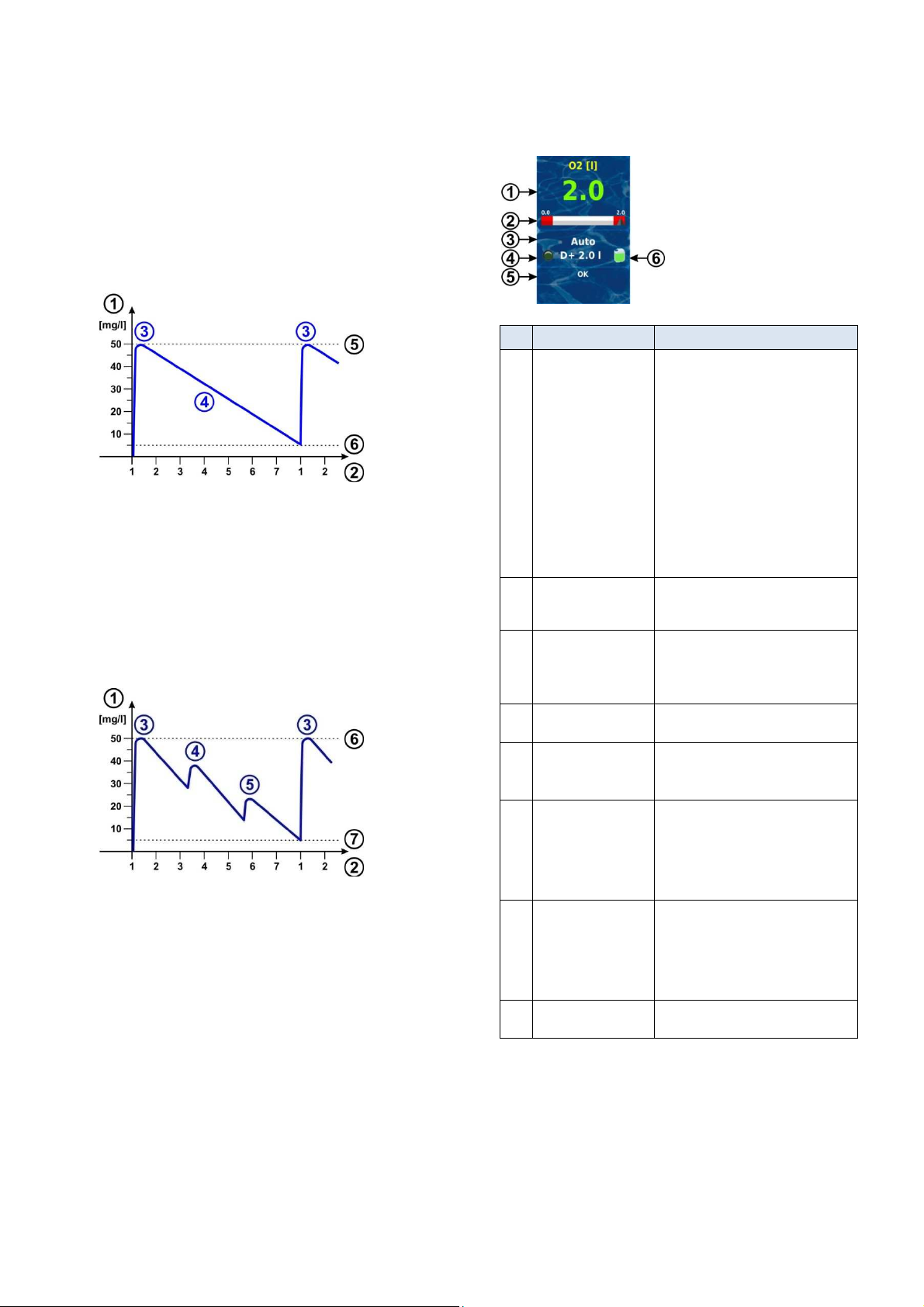
13
Automatic dosage O2 (BayroSoft)
13.1.3 Progression of effective BayroSoft concentration
The following two figures schematically show the progression of the
effective BayroSoft concentration in the water over the course of a
week.
In the first example, the average water temperature is 24°C. Thus, the
two refresh dosages are omitted.
In the second example, the water temperature is 28°C. Therefore the
two refresh dosages provide an interim increase in the effective
BayroSoft concentration in the water.
Automatic dosage at 24°C (without refresh dosages)
1 BayroSoft concentration in the pool in [mg/l]
2 Weekdays (1 = main dosage day)
3 Main dosage
4 Reduced BayroSoft concentration due to product consumption
5 BayroSoft concentration after a main dosage
(ca. 50 mg/l, "shock disinfection")
6 Requisite minimum concentration of BayroSoft (ca. 5 mg/l)
Automatic dosage at 28 °C (without refresh dosages)
1 BayroSoft concentration in the pool in [mg/l]
2 Weekdays (1 = main dosage day)
3 Main dosage
4 1st Refresh dosage after 1/3 week
5 2nd Refresh dosage after 2/3 week
6 BayroSoft concentration after a main dosage
(ca. 50 mg/l, "shock disinfection")
7 Requisite minimum concentration of BayroSoft (ca. 5 mg/l)
13.2 Display in home view
Pos. Content Notes
1
Programmed dose
amount
(Basic dose amount)
2 Measured value scale The measured value scale graphically
3 Current operating state
4a LED symbol The LED symbol illuminates while the O2
4b
Current dosing
direction
and/or type of dosage
4c Current dose amount
(or programmed
dose amount)
5 Alarms All active alarms are shown regarding the
6 Canister symbol Fill level for the BayroSoft canister (red /
During ongoing dosage, the amount
already dosed is displayed, i.e. the display
rises continuously from 0.0 litre to the total
dose amount.
After completing dosage, the display jumps
back to the programmed dose amount.
Colour of measured value display:
green
Normal operation,
everything OK
‘
yellow
Dosage blocked
(missing flow signal
and/or start delay)
rot
Alarm, dosage blocked!
shows the amount already dosed
throughout an ongoing dosage.
Auto / off / alarm / flow / start delay
("x min") /
ongoing dosage (display of remaining
time in minutes "x min")
(BayroSoft) dosage pump is running.
D+ for automatic dosage and M for manual
dosage (M = "manual")
While dosage is running, this shows the
total dose amount of the current dosage
(main dosage, refresh dosage, or manual
dosage).
After completing dosage, the display jumps
back to the programmed dose amount.
O2 (BayroSoft) module.
Alarms whose cause has already been
remediated disappear from the display,
even if they have not been acknowledged.
If there is no active alarm, "OK" appears.
yellow / green)
User Manual PoolManager® 39
Page 40
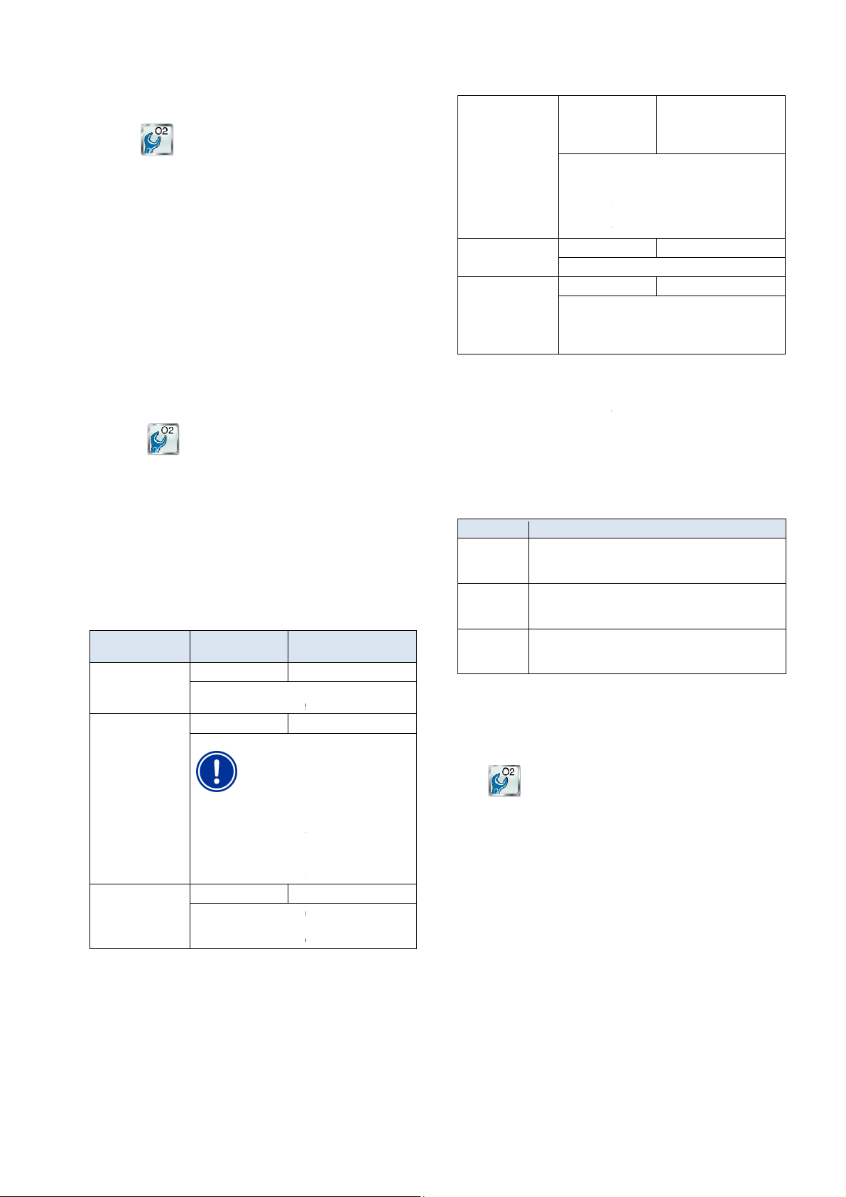
13
contains the following sub
Configuration of all relevant parameters for automatic O2 dosage
Display of average temperature value measured for the entire week
weekday, date, and time can
In this menu, supplemental dosages can be configured; see section
In this menu, the permissible times for BayroSoft dosing can be
stricted. This can be used when, for example, it is preferred there be
(also accessible via the menu
contains the following information:
date and time. The main
dosage and the two refresh dosages are displayed.
When needed, dosage planning can be reset in this menu.
In this case, the current plan is discarded and an entirely new plan is
performed, starting from the current weekday and time
Note: Supplemental dosages are NOT displayed.
Standard setting
Default set Europe
Normal
Temperature compensation
the BayroSoft refresh dosages prove to be too low.
3 l/h
Here, the BayroSoft pump dosing
output is entered. This setting
absolutely must coincide with the
actual pump output on the
used. Otherwise, it's possible that
PoolManager
calculate the requisite pump time for a
dosage, and that the BayroSoft dose
amounts are not correct!
The dosing output for the standard
BayroSoft dosage
40m³
When entering the pool volume, the BayroSoft dose
amount is automatically adjusted to match the pool
size (0.5 litre per 10m³ of pool volume).
Here, the basic dose amount is indicated for
automatic O2 dosage.
The standard value inferred from the pool volume
can be adjusted again. The actual main dose
amount and the two refresh dosages depend on the
average water temperature measure
Monday ... Sunday
Weekday for main dosage.
Active / inactive
After turning on PoolManager
after 12 hours of operation, the BayroSoft pump is
briefly started for ca. 6s in order to hinder product
sedimentation.
Supplemental dosages
provides the option of programming further
supplemental dosages in addition to auto mode with temperature
The temperature dosages are then performed in supplement to the
main dosage and to the refresh dosages. The supplemental dose
fixed, programmed figure and is not
For supplemental dosages, the following parameters can be
configured in the menu "Supplemental dosages":
Here the days of the week on which additional dosing is to
place (one or more) can be selected.
Start time of the additional dosages
(the same for every weekday).
Dose amount for supplemental dosages (the same for every
system should be configured such that on Friday 2.5 l of
BayroSoft is dosed, and 2.0 l each on Monday and Wednesday.
Temperature compensation is not desired.
To do so, the following settings are required:
yroSoft)
Supplemental dosages:
Weekdays = Monday, Wednesday
If temperature compensation is activated, then the main dosage is
and, if applicable, the two refresh
dosages are additionally performed.
Automatic dosage O2 (BayroSoft)
13.3 O2 (BayroSoft) menu
The menu O2 (BayroSoft)
Configuration O2 (BayroSoft)
Average temperature value
O2 dose amount 0.0...99.9 l
-menus.
0.5 litre per 10m³ of pool
volume
(e.g. 2.0 l for 40m³ pool
volume)
and for the individual 1/3 weeks
Date & time
Here, correct configuration of the current
be checked and corrected as needed.
Supplemental dosages
Supplemental dosages.
Operating hours
re
no dosages during night-time hours.
The menu Planned dosing
O2 (BayroSoft))
• Display of the next planned dosages with
13.4 Configuration O2 (BayroSoft)
The following settings can be configured:
Parameter Setting range
Temp. compensation Off / normal / high
Hose config. O2 0.9 l/h / 3 l/h / ...
.
should be set to "high" if
d.
O2 dosage day
6s dosage
13.5
Friday
Active
®
and no later than
PoolManager®
compensation.
amount is
Parameter Explanation
Weekdays
take
Default: Off
Time
Default: Midnight
Dose amount
weekday).
Default: 0.2 l
compensated.
Example:
The
Pool volume 1...5000m³
®
does not correctly
pump being
pump is 3.0 l/h.
User Manual PoolManager®
Menu O2 (BayroSoft)
Sub-menu Configuration O2 (Ba
• Dose amount O2 = 2.5 l
• Temp. compensation = Off
• Dosage day O2 = Friday
• Sub-menu
•
• Dose amount O2 = 2.0 l
compensated for temperature
40
Page 41
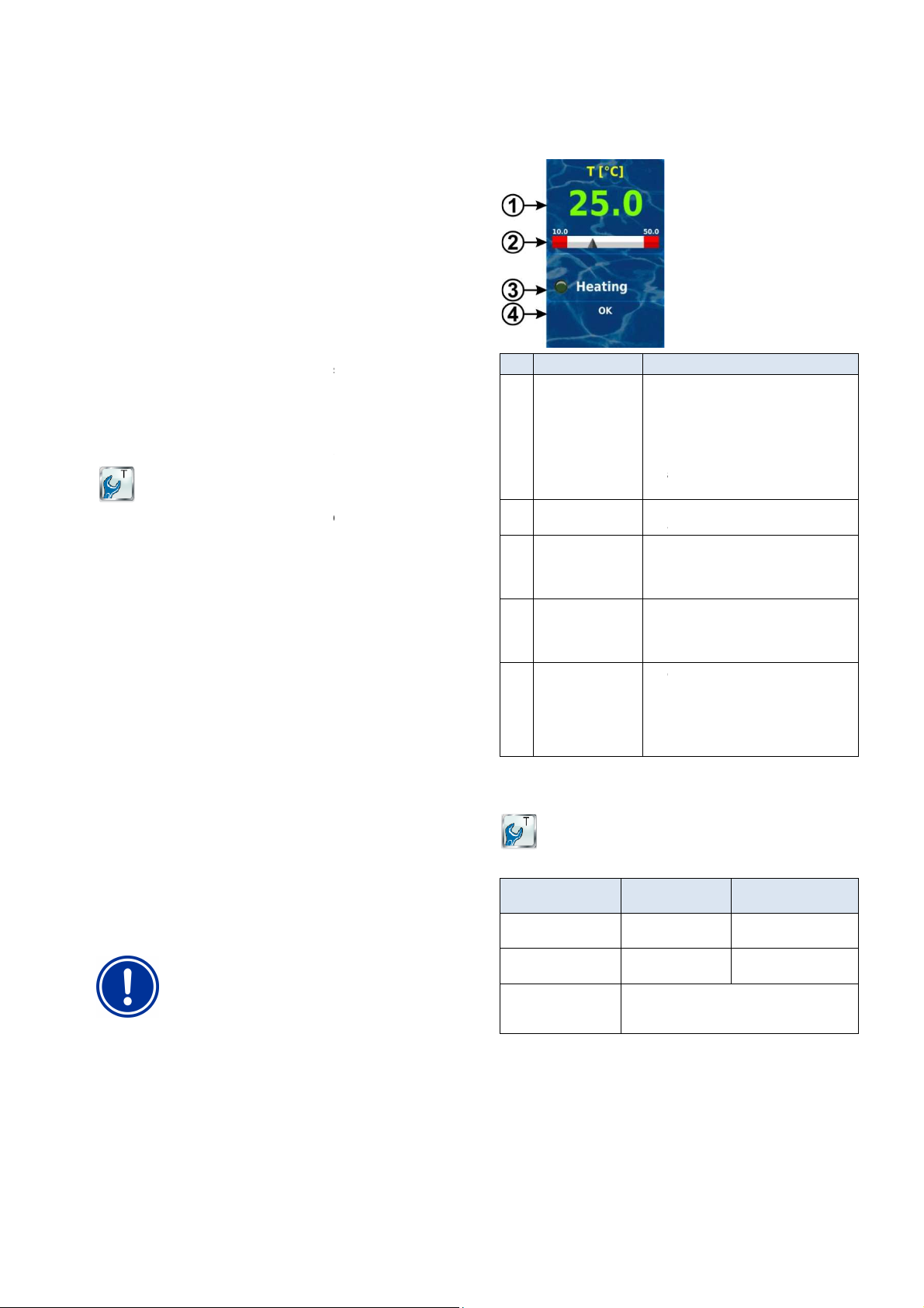
14
has a total of three temperature measurement inputs. A
temperature sensor can be connected to each of them. The three
Temp.1 (T1), Temp.2 (T2), and Temp.3 (T3).
The temperature sensor for the measurement water is connected to
Measurement water temperature
measures the temperature of the measurement water
flowing through the measurement chamber. To that end, a PT1000
temperature sensor is integrated into the measurement chamber and
O2, temperature measur
temperature compensation is used (see section Automatic O2
Various functions and sensor types can be allocated to all three
temperature inputs. Allocation is realised in the following menu:
The following functions can be assigned to each individual
Temperature of measurement water The integrated standard
measurement water sensor in the measurement chamber is
mp. 1 (T1) in the default
Temperature of the pool water (measurement in circulation circuit)
Furthermore, the sensor type used can be configured for each
This is the standard measurement water sensor
This model was used in earlier BAYROL devices
This model was also common in the swimming pool industry
6 sensor, a
be connected parallel to it in order to match the sensor
ange of the two other sensor
has to
Display in home view
Notes
0.0...50.0 °C (input T3: 0.0...75.0 °C)
Colour of measured value display:
green
everything OK
yellow
start delay
Graphic display of current measured value
and alarm thresholds.
The LED symbol is only displayed when the
supplemental
It illuminates when the heating system is
ctive, i.e. when heating is on.
This status is only displayed when the
supplemental
function is being used.
For details, please review the section
All active alarms are shown regarding
temperature measurement.
Alarms whose cause has already been
remediated disappear from the display, even
if they have not been acknowledged.
If there is no active alarm, "OK" appears.
Configuration temperature
uration of temperature measurement is performed in the menu:
Configuration Temperature
There, the following parameters can be configured:
Setting range
0.0…50.0°C
0.0…75.0°C)
0.0…50.0°C
(T3 0.0…75.0°C)
Configuration of functions and sensor types for
T1 / T2 / T3, see section
Temperature sensors
Temperature measurement
14 Temperature measurement
14.1 Overview
PoolManager
inputs are marked
T1 in the default setting.
®
14.2
PoolManager®
connected to the input Temp. 1 (T1).
For PoolManager
®
(BayroSoft) dosage).
14.3 Measured temperatures
Configuration Temperature
temperature input:
• Measurement water
ement for calculating
14.5
Pos. Content
1 Current measured
value
2 Measured value scale
3a LED symbol
Normal operation,
Flow signal missing
or
red
Alarm
heating function is being used.
connected to input Te
• Pool water
• Solar
Water temperature in the solar collector
• Air (indoor hall)
Air temperature in the indoor hall
• Air (outside temperature)
Outside air temperature
14.4 Sensor types
temperature input:
• PT1000 (standard)
used in the measurement chamber.
• KTY83
• KTY16-6 (2kΩ parallel)
IMPORTANT NOTICE!
KTY16-6 temperature sensor
When using a KTY16-
to the measurement r
models.
state.
2kΩ resistor
a
3b Status of heating
and/or solar heating
heating or solar heating
4 Alarms
14.6
Config
Parameter
Top alarm threshold
T1 / T2 / T3
Bottom alarm threshold
T1 / T2 / T3
Sub-menu
Configuration of
temperature sensors
(T3
Standard setting,
default set Europe
10.0°C
50.0°C
Heater.
User Manual PoolManager®
41
Page 42
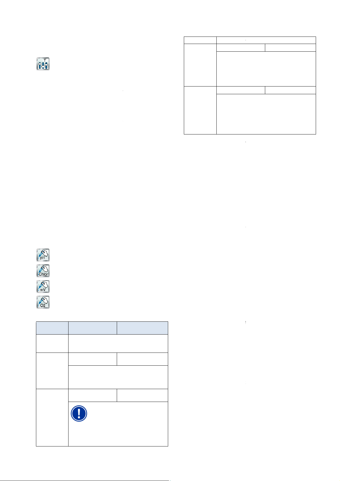
15
Calibration of temperature measurement is performed in the menu:
Select the temperature input to be calibrated
T1 / T2 / T3
temperature (water, solar, air) for
the corresponding input on the thermometer
Enter the temperature measured as the calibration value
If the displayed measured value signal is stable and is no longer
changing in a relevant manner, then confirm calibration
Check the calibration results displayed and close calibration by
For each module pH, chlorine (Cl) / Bromine (Br), mV (redox), and O2,
there is the option of adding additional product to the
Manual dosing is restricted in time and will automatically end after the
dosing duration has selected has passed. Furthermore, manual dosing
can be manually stopped at any time. During manual dosing, the
uns continuously, i.e. at a dosing output of 100%.
Manual dosing can be blocked by alarms; see section
Manual dosing can be started in the following menus:
Manual dosing chlorine(Cl) / bromine(Br)
Manual dosing mV (Cl) / manual dosing mV (Br)
The following displays and settings are available in each menu:
Standard setting
Default set Europe
Display of current measured value for orientation
pH:
Cl / mV:
Dosage direction in manual dosing can only be selected
for pH if pH control is working bi
dosing always occurs in the
pH / Cl / mV: 1.5 l/h
O2: 3 l/h
Here, the dosing output of the corresponding
dosage pump is entered. This setting
must coincide with the actual
pump output on the dosage
used. Otherwise, PoolManager
calculate the requisite pump runtime correctly
for manual dosing, and under certain
circumstances the desired amount may not
be dosed!
Here, the desired dosing amount is set for manual dosing.
calculates the duration of manual dosing
based on the dosing amount and hose configuration.
For a hose configuration with 1.5 l/h and a
of 1.0 l, a manual dosing duration of 40 min. is yielded.
Here, the duration of manual dosing can be established. If
this setting is changed, then PoolManager
recalculates the dosing amount
For a hose configuration of 1.5 l/h and a manual dosing
duration of 30 min, a dosing amount of 0.75 l is yielded.
start manual dosing
In addition to manual addition of t
possible to select a volume of single, double, or triple the base dosing
amount with O2 (BayroSoft) manual dosing.
Menu view changes during ongoing dosage. All relevant data for the
Remaining dosing time [min]
The only values that can appear here are 0% or 100%. If a
dosing output of 0% is shown, then manual dosing is blocked by
status of the corresponding dosage pump. If "pump
off" is shown, then manual dosing is blocked by an alarm.
Operating mode pH / mV / O2 (manual / flow / alarm)
If dosing is running, then PoolManager
"alarm" or "flow" is displayed, then manual
dosing is blocked by an alarm or due to there being no flow signal.
can be stopped at any time by pressing the button
Just like normal automatic dosing, manua
(Depending on the configuration in the menu
(blocks only manual dosing in D+ dosage direction)
(blocks only manual dosing in D
After the end of an alarm status, the block on manual dosing is
released and the remaining amount is dosed.
If manual dosing is started during start delay, then the start delay will
Manual dosing
14.7 Calibration
Calibration Temperature
Please perform calibration as follows:
1.
1-point Calibration Temperature
2. Measure the corresponding
3.
4.
pressing continue.
5.
pressing finished.
15 Manual dosing
15.1 Overview
water via manual dosing.
dosage pump r
alarms.
swimming pool
Blocking via
by
Manual dosing
amount
Manual dosing
duration
Pressing the button
0.1...10.0 l
PoolManager®
Example:
1...240 min
configuration.
Example:
1.0 l
40 min
using the hose
will start dosage.
dosing amount
®
also
Note:
he desired dosing amount, it is also
Ongoing dosing
ongoing dosage are now shown:
• Current value pH / mV
• Dosed amount [l]
•
• Dosing rate [%]
15.2 Menu manual dosing
Manual dosing pH
Manual dosing O2
Parameter Setting range
Current
measured value
pH / mV
Manual dosing
direction
Hose config.
pH / mV / O2
D- / D+
direction dosage, manual
direction indicated.
0.9 l/h / 3l/h / ...
absolutely
D-
D+
-directionally. In mono-
pump being
®
may not
an alarm.
• Dosing direction
The current
•
"manual."
If, instead of this,
Manual dosing
Manual Dosing.
15.3 Blocking via alarms
the following alarm statuses:
• Flow signal missing
• Level alarm
• Upper alarm
• Lower alarm
end prematurely.
®
is in the operating mode
l dosing can be blocked by
alarm settings)
- dosage direction)
Stop
User Manual PoolManager®
42
Page 43

16
Shock chlorination may only be performed by a
User
chlorine
concentration in the pool is usually significantly
blocked by a top
alarm, such that the chlorine value can also rise to be
Calculate the correct dosing amount for shock
Close off the pool for swimming following shock
Swimming may not take place again until the
below 3
during a
pump test while circulation is not running, then gaseous
chlorine may be produced when ChloriLiquid meets
running or
Safety functions and alarms
15.4 Special case, shock chlorination
Requisite user qualification:
TRAINED SPECIALIST
TRAINED SPECIALIST as defined in the chapter
qualification.
HAZARD!
Overdosage via shock chlorination
With shock chlorination, the standard
exceeded. Shock chlorination is not
significantly higher than the top alarm threshold!
Potential consequence: Gravest degree of injury,
heavy material damage.
•
chlorination carefully.
•
chlorination.
•
concentration of free chlorine has dropped
mg/l (perform DPD measurement)!
Shock chlorination is a special kind of manual dosing. PoolManager®
Cl offers shock chlorination in the menu Manual dosing mV (Cl).
Shock chlorination is a special kind of manual dosing. PoolManager®
PRO offers shock chlorination in the menu Manual dosing Cl (or Br).
For shock chlorination, the dosing amount is calculated based on the
pool volume. In doing so, the recommended amount of 0.2 litre
ChloriLiquid per 10m³ of pool volume is used as a foundation.
However, the thus calculated dosing amount can still be changed
manually. For effective shock chlorination, the chlorine concentration
in the pool should be at least 5 mg/l.
Pressing the button start shock chlorination will start dosing.
Otherwise, the shock chlorination process corresponds exactly to
normal manual dosing.
15.5 Special case, pump test (pH / Cl or Br / mV / O2)
‘HAZARD!
Gaseous chlorine produced from dosing in
standing water in a pump test
If the there is a dosing of maintenance product
16 Safety functions and alarms
16.1 Overview
PoolManager® continuously monitors all relevant data and operating
statuses in order to guarantee safe operation and optimum water
quality.
If PoolManager® discovers a problem while doing so, then it will
generate an alarm message notifying of the problem. Some alarm
statuses block product dosing until the alarm's cause has be
remediated.
PoolManager® monitors the following alarm statuses.
• Upper and Lower alarms (pH, mV, temperature)
are triggered when there is a measured value outside the
configured alarm thresholds.
• Flow alarm
is triggered when circulation is not running or if there is no
measurement water flow for some other reason.
• Level warning (pH, Cl, mV, O2)
is triggered when a canister with maintenance product (pH minus,
ChloriLiquid, or BayroSoft) contains only a certain residual amount
(e.g. 5 l).
The suction lance in the product canister delivers a corresponding
signal once the threshold is reached.
Level warning and level alarms can be deactivated in the menu
"Alarm settings" if there is no suitable low-level signal available.
• Level alarm (pH, Cl, mV, O2)
is triggered when a canister with maintenance product (pH minus,
ChloriLiquid, or BayroSoft) is empty.
Level warnings and level alarms can be deactivated in the menu
"Alarm settings" if there is no suitable low-level signal available.
• Intelligent dosing monitoring (pH, Cl, mV)
is triggered when PoolManager® does not successfully approach
the setpoint within a predefined time (typically 60 minutes). In this
case, PoolManager® will assume there is a potential problem and
block further dosing.
• Battery alarm
is triggered when the voltage on the buffer battery installed on the
PoolManager® unit drops below the threshold of 2.70V. In this
case, the battery should be replaced within a few weeks. The
buffer battery supplies PoolManager® real-time clock with voltage
while turned off.
with pH minus.
Potential consequence: Death or the gravest
degree of injury,
heavy material damage.
• Perform pump tests while circulation is
absent of product dosage.
The pump test function is used to quickly check whether the individual
dosage pumps are connected correctly and are fundamentally
operational. There is no alarm block during a pump test, i.e. the
corresponding pump should definitely be running during a pump test. If
that is not the case, then there is an error in the pump or in the
electrical connection.
The duration of the pump test is limited to a maximum of 60 seconds
for safety reasons.
Otherwise, the pump test process corresponds exactly to normal
manual dosing.
User Manual PoolManager® 43
Page 44
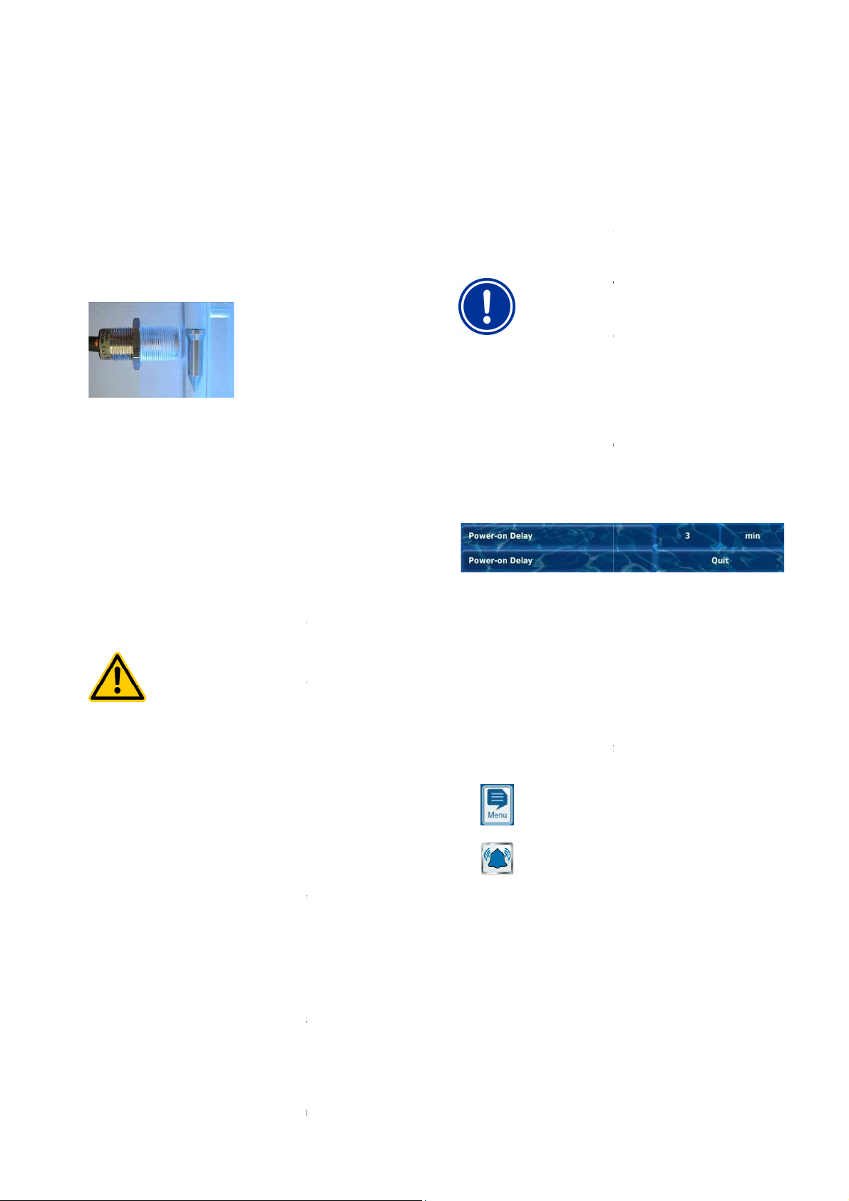
16
offers two separate inputs for flow monitoring:
Measurement water monitoring (standard)
Measurement water flow is usually monitored with an inductive
proximity switch integrated into the measurement chamber. Flowing
the measurement chamber. If the float rises to
the level of the proximity switch, then the latter will supply the flow
Inductive proximity switch (left)
and float (right)
The proximity switch has three connection lines and is connected to
). The flow signal is ALWAYS
monitored; this monitoring cannot be deactivated for safety reasons.
Optionally, an additional signal can be used to monitor the circulation
so usually entails pressure sw
). Alternatively, BNC connector
can be used, which is internally connected with terminal
default configuration is for monitoring
this input to be deactivated. It can be activated as needed in the menu
connected to the input instead
of the inductive proximity switch as the sole sensor for flow monitori
This option can also be configured in the menu
Gaseous chlorine produced from dosing in
standing water via unreliable flow monitoring.
If only one single sensor on input
flow monitoring, then there is risk for dosage in
standing water in the event of an error. Poisonous
chlorine gas can be yielded when ChloriLiquid and pH
Potential consequence: Death or the gravest
Ensure that the sensor being used is functioning
dosage pumps are only
supplied with power while circulation is running;
via the circulation pump.
Automatic / manual acknowled
offers two different options for handling a missing flow
(Default, flow alarm acknowledgement = automatic)
does not assess a missing flow signal as
an error, but rather as a normal operating state. For most swimming
pools, circulation only runs in intervals and not around the clock. In
this case, it is entirely normal for PoolManager
signalises the missing flow signal only as
a normal operating status, not as an alarm status. The special
is being used for
mechanisms for signalising alarms are not activated (blinking display,
Dosage is blocked for as long as no flow signal is sent
signal returns and the start delay has passed, PoolManager
automatically returns to normal control system operation.
Alarm for missing flow signal
(Flow alarm acknowledgement= manual)
This option is only sensible for swimming pools where
around the clock without interruption. PoolManager
missing flow signal as a grave error that is signalised with various
IMPORTANT NOTICE!
Manual flow alarm
After the flow signal returns, dosage remains bloc
this option. Blockage is not released until after the flow
signal has returned
acknowledged manually.
or once the flow signal has returned
after an interruption (e.g. after tu
configurable delay is initiated. PoolManager
time so that all measured values can stablise. No dosing is performed
during a start delay. Regular operation does not start again until the
elay is displayed as follows in the
The first line shows the current remaining runtime on the start delay in
[min]. The second line makes it possible to end start delay prematurely
acknowledgement button.
uses multiple mechanisms for clearly signalising alarms
Striking blinking of the entire display
Blinking ends immediately upon touching the touchscreen.
Automatic jump to the menu
Alarm overview
(Provided this function is activated for the corresponding alarms in
nal ends immediately upon touching the
Switch output (potential free or 230 VAC) for connecting external
systems to signalise or record alarm statuses (terminal block [25]
ked in
the flow alarm has been
Safety functions and alarms
16.2 Flow monitoring
16.2.1 Input terminal blocks for
flow monitoring
While PoolManager
16.2.1.1
®
acoustic alarm, etc.).
. Once the flow
®
16.2.2.2
circulation runs
®
assesses a
water raises the float in
signal.
PoolManager® terminal block [2] (Flow
16.2.1.2 Circulation monitoring (optional)
circuit.. Doing
PoolManager® terminal block [6] (IN1
IN1 (Flow)
block [6] (IN1) . PoolManager®
Alarm settings (Flow alarm settings).
It is also possible to use the sensor IN1
alarm settings).
HAZARD!
minus come together.
itch connected to
Alarm settings (flow
IN1
of
ng.
alarm mechanisms.
16.3 Power-on delay
After turning on PoolManager®
start delay has passed.
The Power-on D
by pressing the
16.4 Alarm signalisation
PoolManager®
to the user:
•
•
Note: The menu
as follows:
and
rning circulation back on), a
®
will wait for that period of
Alarm overview:
Alarm overview
can also be called up at any time
degree of injury,
heavy material damage.
•
reliably.
• Ensure that PoolManager®
16.2.2
see section locking
gement
‘PoolManager®
signal:
16.2.2.1 No alarm for missing flow signal
In this option, PoolManager®
®
to not receive a flow
signal in times without circulation.
Accordingly, PoolManager®
• Acoustic alarm signal
the menu Alarm settings)
The acoustic alarm sig
touchscreen.
• Alarm relay connection
(Alarm)).
See section Alarm relay.
User Manual PoolManager®
Menu hotkey
Alarm Overview
44
Page 45
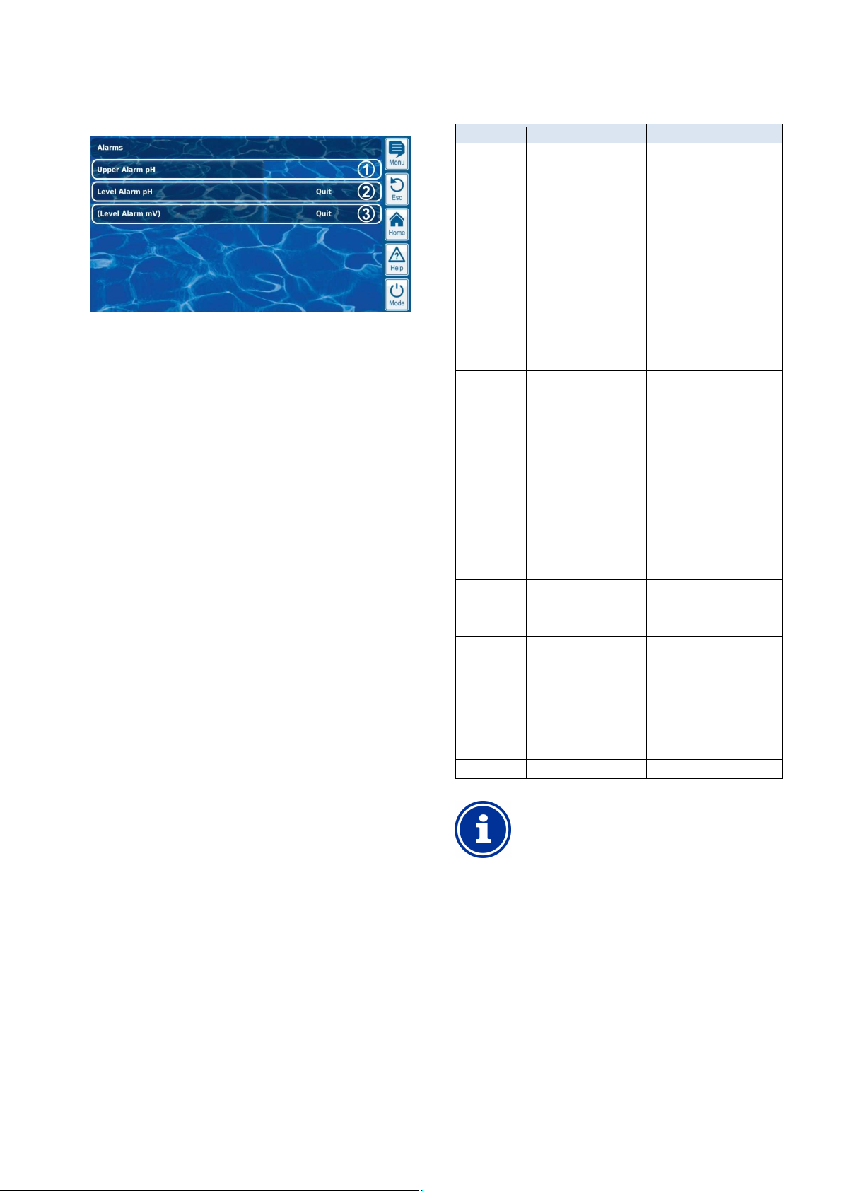
16
It is also not deleted until the alarm's cause has been
The alarm delay for the flow alarm can be extended as
Safety functions and alarms
• Alarm display in home view
Alarms are shown in the alarm overview as follows:
1 The alarm is active, i.e. the alarm cause has not yet been
remediated. But the alarm has already be acknowledged.
Therefore, the acknowledgement button is no longer displayed.
2 The alarm is active, i.e. the alarm cause has not yet been
remediated. The alarm has not yet been acknowledged.
Therefore, the acknowledgement button is displayed.
3 The alarm is no longer active, i.e. the alarm cause has been
remediated. That is why the alarm appears in brackets.
However, the alarm has not yet been acknowledged.
Therefore, the acknowledgement button is displayed.
If an alarm becomes inactive, i.e. the alarm cause has been
remediated, and the alarm has been acknowledged by the user, then it
will disappear completely from the alarm overview.
No acknowledgement button appears for the flow report if the setting
Alarm for missing flow signal is set to no, as no acknowledgement is
required in that case.
16.4.1 Alarm display in home view
All active alarms are displayed in the Home view; see section Home
view.
16.5 Dosage blocking via alarms
Alarms generally result in dosage blocking. The block is automatically
released as soon as the alarm cause has been remediated.
It is not necessary for a user to acknowledge an alarm in order to end
blocking (however, the alarm continues to be displayed in Alarm
overview until acknowledgement).
The following alarms are handled in deviation to that mechanism:
• If the setting Alarm for missing flow signal is set to yes, then
dosage blocking is not ended until a flow signal is present again
and the flow alarm has been acknowledged by the user. Dosage
will then be released after start delay has passed.
• If the setting Alarm for missing flow signal is set to no, then
dosage blocking is not ended once a flow signal is present again.
Dosage will then be released after start delay has passed.
• The menu Alarm settings can be used to establish whether a level
alarm will lead to dosage blocking. The default setting is that a
level alarm will block dosage of the respective control module
(pH, Cl, mV, O2).
• After a dosage alarm, dosage is released immediately after
manual acknowledgement of the alarm.
16.6 Table overview
Alarm Dosage blocking Notes
Upper alarm
(pH, mV, Cl,
Br)
Lower alarm
(pH, mV, Cl,
Br)
No
flow signal
No
flow signal
Level alarm
(pH, mV, O2,
Cl)
Dosing alarm
(pH, mV,
Cl, Br)
Power-on
Delay
Battery alarm No
Only for dosage
direction D+
(only for the respective
control module)
Only for dosage
direction D(only for the respective
control module)
Yes
(for all control modules)
Yes
(for all control modules)
Yes
(Only for the respective
control module)
can be deactivated
in the menu
Alarm setting
Yes
(for the respective module
only)
Yes
(for all control modules)
The block is released as soon
as the measured value drops
back below the top alarm
threshold
The block is released as soon
as the measured value climbs
back over the top alarm
threshold
Alarm for missing
flow signal = no:
Start delay will first run through
its time after the flow signal
returns. Dosage is then
released again.
Acknowledgement is not
necessary
Alarm for missing
flow signal = Yes:
Start delay will first run through
its time after the flow signal
returns and the alarm is
acknowledged. The dosage is
then released again. Manual
acknowledgement is
absolutely necessary.
After the level signal returns,
dosage is released again.
After acknowledging the
dosage alarm in the Alarm
overview, dosage is released
again.
Start delay runs through its
time after starting
PoolManager® and after the
flow signal returns. Dosage is
released after that time has
passed. Start delay can be
prematurely ended via manual
acknowledgement in Alarm
overview.
INFO
Alarm delay
All alarms are shown only after an alarm delay of 5s.
remediated for at least 5s.
needed in the menu Alarm settings.
User Manual PoolManager® 45
Page 46
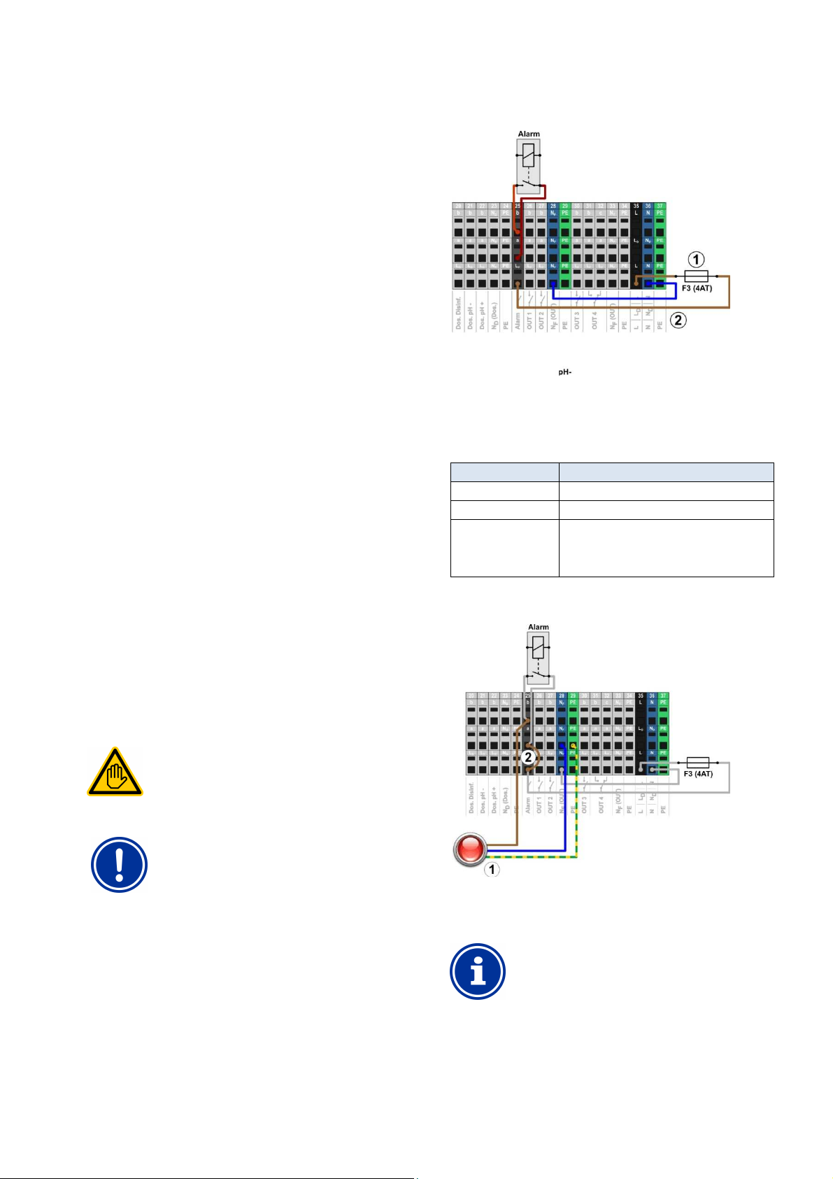
16
An electrical connection to an alarm relay may only be
SPECIALIST as
Observe the maximum permissible currents for the
alarm relay (max. 4A) and for the sum of all relay
unit's neutral conductor N and protective
earth PE can be connected to the terminal blocks
and PE as shown in the
Safety functions and alarms
16.7 Alarm settings
The following adjustments can be made in the menu Alarm settings.
16.7.1 Acoustic alarms
The following acoustic alarms can be activated and deactivated
individually:
• Acoustic signal for flow alarm
• Acoustic signal for level alarm
• Acoustic signal for miscellaneous alarms
• Acoustic signal for service notifications.
16.7.2 Flow alarm settings
• Duration of start delay
• Alarm delay for the flow alarm
• Flow alarm acknowledgement (automatic / manual)
• Input for flow monitoring:
• Flow [2]
• IN1 [6] / BNC
• Flow [2] & IN1 [6] / BNC
(Double flow monitoring)
16.7.3 Level alarm settings
• Level alarm pH active/inactive
(Level alarm can be deactivated if no low-level signal is available)
• Level alarm Cl, mV and/or O2 active/inactive
(Level alarm can be deactivated if no low-level signal is available)
• Dosage for level alarm (yes / no)
(If the canister is not yet entirely empty when a level alarm arises,
then dosage can be continued despite level alarm)
• Optional level input for pH plus
• Residual volumes in canister for level signal from suction lance
(Individually configurable for each canister)
The following figure shows the internal wiring on the alarm relay. All
connections shown are run internally as conducting paths.
1 Fuse F3 (4AT)
2 230V~ phase LF for the alarm relay and the supplemental
The terminal block [25] for the alarm relay is set up as follows:
functions (secured with 4A)
Terminal Function
b Working contact
a Centre contact
LF Supply phase 230VAC for alarm relay and
supplemental functions. Can be bridged to the
centre contact if needed in order to control
230VAC devices.
The following figure schematically shows the connection of a 230V~
alarm unit on the alarm relay.
16.8 Alarm relay
The alarm relay offers the chance to connect an external alarm device,
or to notify external systems of current alarms.
The alarm relay is turned on as long as there is at least one active
alarm and it has not yet been acknowledged.
16.8.1 Electrical connection
Requisite user qualification:
ELECTRICAL SPECIALIST
performed by an ELECTRICAL
defined in the chapter User qualification.
IMPORTANT NOTICE!
Observe maximum flows
switch outputs being used in 230V~ (in sum, max. 4A)
Please also refer to the Chapter 230V~ Power supply.
1 Alarm unit 230V~
2 Wire bridge in the terminal box from phase LF to centre
relay contact a
INFO
Connection of neutral conductor N and PE
An alarm
intended for the purpose NF
figure.
When using the alarm relay as a potential free switch, the wire bridge
(2) is omitted and the connection is realised on terminal blocks [25a]
and [25b].
User Manual PoolManager® 46
Page 47
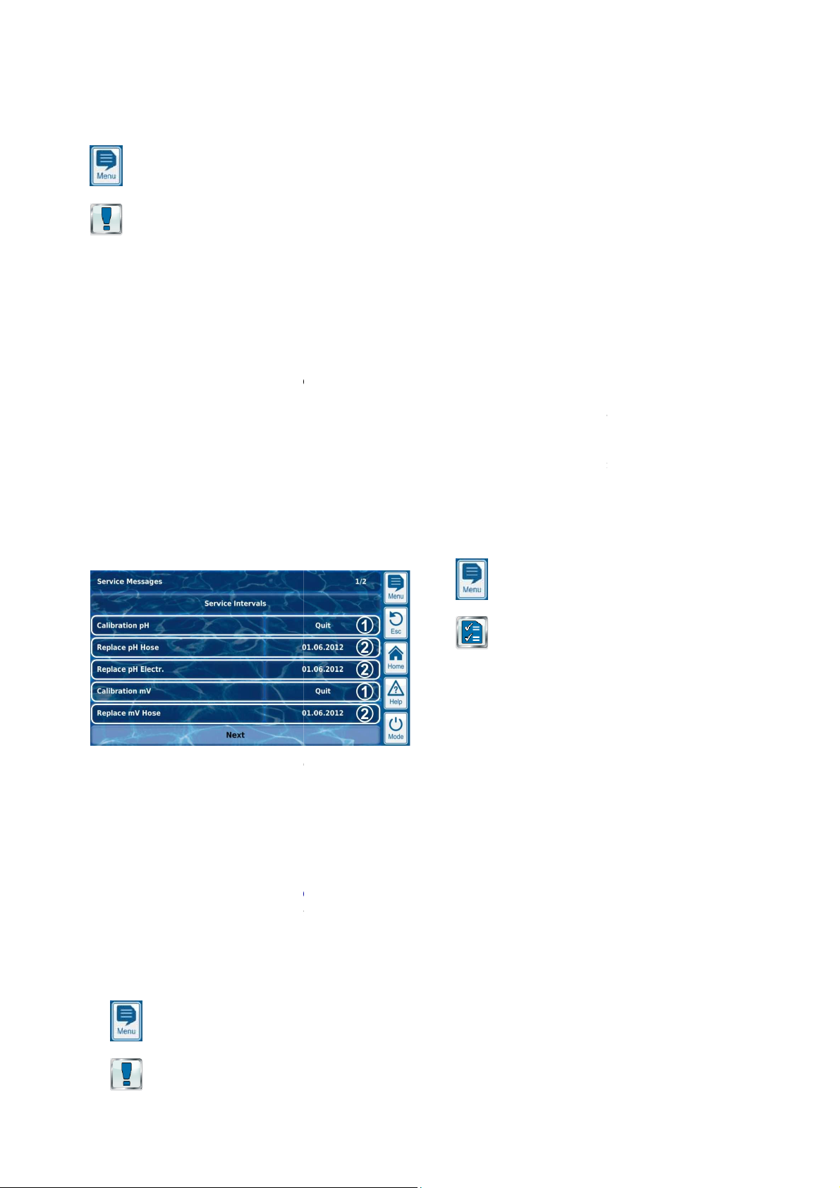
17
is called up as follows:
facilitates targeted planning of certain
(pH, mV, Cl or Br, T)
on the dosage pump (pH, mV, O2, Cl)
A time interval in [months] can be defined for each service process in
After the configured period of time has
will automatically provide a reminder that the
etting for all service intervals is set to 0 months, i.e.
inactive. In order to activate the function, an interval of 1...60 months
has to be set for the service processes desired. Resetting the setting
to 0 months will deactivate the service message again
, all planned service processes are
shown along with their due date. If needed, the planned date
can be corrected manually.
The service processes are displayed in the menu as follows:
service messages are already due. Therefore, an
acknowledgement button is displayed.
Pressing the acknowledgement button will reschedule the
process and the newly calculated due date will be
These service messages are not yet due.
the due date is displayed.
ignalising due service messages
Due service messages are signalised as follows:
Blinking ends immediately upon touching the touchscreen.
Service messages
can also be called up at any
Acoustic alarms
corresponding alarms in the menu
alarm signal ends immediately upon touching the
Due service processes are signalised at 8:00 a.m. on the
scheduling service messages
scheduling, PoolManager
adding the configured service interval to the
For pH calibration, a service interval of 3 months is configured.
On 6 December 2012, it will be re
The new due date is 6 March 2013.
scheduled in the
Change to the service interval in the menu
Acknowledgement of a due service message
Successful performance of calibration (for calibration messages
schedule service messages
is called up as follows:
The event log is a record of all important events involving
with date and time. PoolManager
to 500 events. When that number is met, the oldest events are
The event log is an important tool in controlling proper operation of the
swimming pool system and analysing potential problems.
g events are logged individually in the event log:
turning on and off
Alarm states (beginning and end)
Parameter changes with old and new value
O2 dosages and average temperature values
Reset to default values (default reset)
displays all entries in the event log in an easy
manner. That is why there is no detailed presentation of the individual
Service messages
17 Service messages
The menu Service messages
Menu hotkey
Service Messages
The function Service messages
service processes:
• Calibration Interval(pH, mV, Cl or Br, T)
Recommended interval: 1 month
• Electrode exchange
Recommended interval: 12 months
• Hose exchange
Recommended interval: 12 months
the sub-menu Service intervals.
passed, PoolManager®
planned service process is due.
The default s
In the menu Service messages
calculated by PoolManager®
• Acoustic alarm signal
(Provided the function
The acoustic
touchscreen.
Note:
corresponding day.
17.2 Re-
When reservice message by
current date.
.
Example:
•
•
Service messages are re-
•
•
•
only)
• Calling up the function Re-
menu Service intervals
®
is activated for the
Alarm settings)
recalculates the due date of a
-scheduled.
following cases:
Service intervals
in the
18 Event log
The event log
1
These
displayed.
2
Therefore,
17.1 S
• Striking blinking of the entire display
• Automatic jump to the menu
Note: The menu Service messages
time as follows:
Menu hotkey
Event log
PoolManager®
overwritten with new ones.
18.1 Events
The followin
• PoolManager®
•
• Calibration with exact data
•
•
• Manual dosing
• Dosed product volumes
• Remote access
• Software updates
• Access code reset
•
PoolManager®
®
has memory for up
-to-follow
Menu hotkey
Service Messages
events.
User Manual PoolManager®
47
Page 48
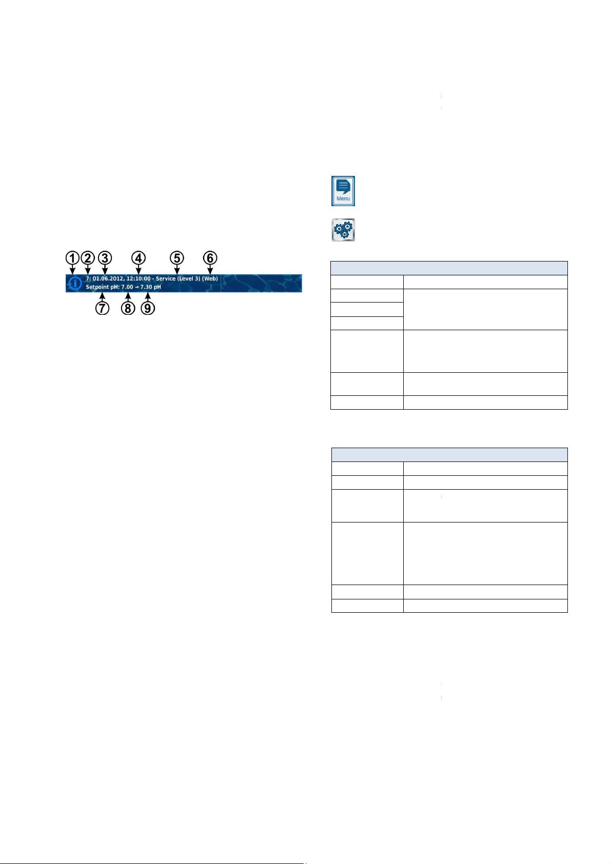
19
For each event, the following supplemental information is stored and
(Provided a user can be allocated to the event, e.g. parameter
changes, calibrations, manual dosing, etc.)
Remote access from the local network (
Web)
Here is a detailed explanation of how an event is displayed using the
Service (Level 3)
(BayroSoft) dosage
This example of O2 (BayroSoft) dosing is intended to illuminate what
Main dos.O2 ended (2.4/2.4l)
Main dos.O2 continued(1.0/2.4l)
Main dos.O2 blocked (level)
Main dos.O2 started (2.4l)
This series in the event log is caused by the following events
starts O2 main dosing with a dosing
After 10 minutes, however, the BayroSoft canister is empty. That
triggers a level alarm, which blocks O2 main dosage.
On the next morning at 8:30 a.m., the empty BayroSoft canister is
e level alarm ends, and O2 main dosage is continued, although
there was already 1.0 litre of BayroSoft dosed prior to the level
alarm. Thus, another 1.4 litres need to be dosed.
At 8:44 a.m., the O2 main dosing ends regularly after the dosing
litres is fully met.
is called up as follows:
The menu provides the following setting options:
Configuration of the desired menu language
See section
Entry of the name for the PoolManager
name is shown in the browser during remote access
and makes it possible to distinguish among multiple
Set date and time, and configuration of associated
Settings for energy saving mode
The following functions are available in the menu Date & time:
Display and configuration of current
Display and configuration of current date
Display of current weekday.
The weekday is automatically set correctly upon
setting the date.
Configuration of the change between summer and
Standard setting (default): Auto
The current time is moved forward by one hour
The current time is moved back by one hour
sets time as follows in automatic
On the last Sunday in March, time is moved forward
On the last Sunday in October, time is moved back
from 03:00 a.m. to 02:00 a.m.
Once the automatic change has been made, the
notification with the newly configured time. It can then be checked and
Device settings
18.2 Information displayed
displayed in the event log:
• Date and time
• User
• Type of access
• Local device operation (local)
•
• Remote access from the Internet (
18.2.1 Event display
example of a parameter change:
1 Symbol (depending on type of event)
2 Serial number
3 Date
4 Time
5 User name and access level, e.g.
6 Type of access
(local / LAN / Web)
7 Designation of changed parameter
8 Old parameter value (prior to change)
9 New parameter value
18.2.2 Example, O2
the event log makes possible:
1 06.06.2012 08:44
2 06.06.2012 08:30
3 06.06.2012 08:30
(Level alarm) end
4 06.06.2012 08:10
5 06.06.2012 00:10
Level alarm O2
6 06.06.2012 00:00
• At midnight, PoolManager®
amount of 2.4 litres.
•
•
replaced.
LAN)
• Th
•
amount of 2.4
19 Device settings
The menu Device Settings
Menu hotkey
Device Settings
Menu Device settings
Menu Language
Menu Style
Icon Style
Background image
Controller name
devices.
Date & time
options
Energy saving mode
individualisation
19.1 Date & time
Menu Date & time
Time
Date
Day of week
Summer / winter time
auto / manual
Time +1h
Time -1h
winter time.
Auto
Manual
user
PoolManager® automatically
configuration:
•
from 2:00 a.m. to 3:00 a.m.
•
corrected manually as needed.
The change is made automatically
The change is made manually by the
time
unit will show a
®
unit. This
User Manual PoolManager®
48
Page 49
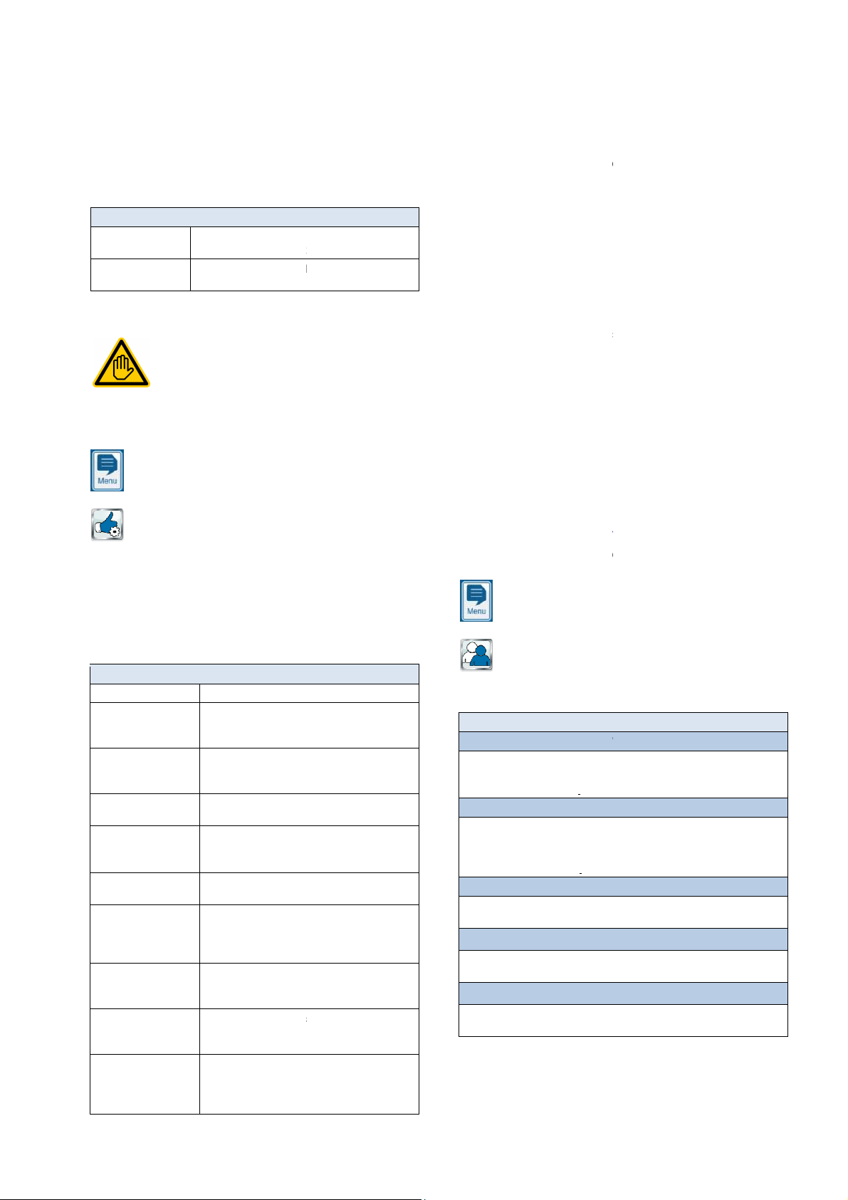
20
When energy saving mode is activated, PoolManager
brightness and enters energy saving mode after a co
of time. A simple touch ends energy saving mode and increases the
Energy saving mode
Time in [min] after which energy saving mode
activated when no user entries are made.
Activates and deactivates the toggle to energy
saving mode after the configured amount of time.
Service functions
be used by a TRAINED SPECIALIST as defined in the
is called up as follows:
service staff that are needed, for
example, for the system's basic configuration (pool volume,
Furthermore, a software update can be performed or the maintenance
menu offers the following functions:
Configuration of dosing pump parameters
(Standard pump or membrane pump,
dosing rate). See section
Display of battery voltage
(Buffer battery for internal real
Reset of all parameter settings
f complete system
configurations via remote access or USB stick.
Managing system configurations.
up menu sequence for first
®
so, the new software has to be copied to a USD
memory stick. See section
Configuration of the PoolManager
Activation of special functions for trade shows and
training sessions (e.g. internal simulation of
Special functions for users
with Master (level 4) access rights.
Separate documentation is available for
may only
Management of system configurations
This menu provides you with a wide range of options to load or save
entire system configuration. The source or destination can be a PC in
remote access or a USB memory stick. Furthermore,
can also internally store four more configurations in addition to the
You can select one system configuration as the source and transfer it
into another system configuration (destination). The current system
can also be used as a source or a destination.
A system configuration includes all PoolManager
Access data (usernames, access codes, passwords)
follow name can be assi
in order to distinguish various configurations from each other.
delivers comprehensive, flexible, and high
user administration. This makes it possible to define individualised
ss rights for each of the system's users. Furthermore, the rights
for remote access can also be configured very flexibly for each
individual user. In doing so, it's even possible to make a distinction
between remote access from the local network and from t
i.e. you can release more functions for remote access from the local
network than for remote access from the Internet as needed.
Menu user administration
is called up as follows:
menus with the following
Standard users (menu access only)
menu can be used to configure the access codes for standard
Individual users (menu access & remote access)
menu can be used to create individual users and configure their
rights. Remote access from the local network or from the Internet can be
Enable remote access for various functions
Enable or disable remote access to various functions like access to the mode
on functions
add
output OUT 1...OUT 4, filter pump, heating etc.
functions
Adjust required user level for various functions like 1 point calibration, manual
individual menus and functions are described in the detail in the
Service functions
19.2 Energy saving mode
screen's brightness.
This function can be configured in the menu
Menu Energy saving mode
Energy-saving mode
Energy saving mode
(active / inactive)
20 Service functions
Requisite user qualification:
TRAINED SPECIALIST
The functions in the menu
The menu Device settings
chapter User qualification.
Menu hotkey
®
reduces screen
nfigured amount
20.1
PoolManager®
active configuration.
is
configuration
®
exclusions are:
•
settings. The only
• Maintenance method
• Network (IP) settings
An easy-to-
gned to every copied configuration
21 User management
PoolManager®
acce
-performance
he Internet,
Service Functions
This menu has special functions for
configuration of dosage pumps, etc.).
problem (Cl / Br / O2) can be changed.
Specifically, the
Menu Service Functions
Pool volume Pool volume in [m³]
Configuration of dosing
pumps
Device information
and test functions
Reset to
defaults
Management of
system configurations
Commissioning
Step by step
Software update
(from USB stick)
Device type & care
method
Trade show settings
Master level functions
future test functions.
to default settings.
Import and export o
See section
Callsection First start-up.
Update to PoolManager
USB stick).
program
(Cl / Br / O2)
measured values)
functions as needed.
Dosing pumps.
5 device software. To do
-time clock),
start-up. See
Software update (from
®
maintenance
these
21.1
The menu User administration
Menu hotkey
User administration
The menu contains multiple subconfiguration options:
Menu User administration
This subusers.
See section Standard users.
This sub-
released for individual users.
See section Individual users.
code, calibration, manual dosing
Enable remote access for add-
Enable or disable remote access to
Adjust r user level for various
dosing, accessto the mode menu
The
following sections.
-on functions like universal swich
User Manual PoolManager®
49
Page 50
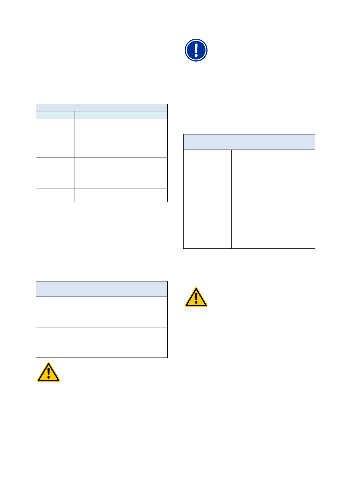
21
Unauthorised access possible from using known
Access codes facilitate access to critical areas on the
system. Unauthorised access can lead to dangerous
Configure individualised access codes. Under no
circumstances should the preconfigured standard
codes are known and available
as needed, even after longer periods of time. The
access codes are absolutely necessary for numerous
Despite the highest security standards, there is
undamentally a residual risk for potential unauthorised
access when releasing remote access. Unauthorised
User management
21.2 Users
You have to login as a user in order to receive access rights for certain
functions on PoolManager®.
For menu access, choose a username and enter the corresponding
access code (max. 6 digits).
During remote access, logging in with a special username (only for
remote access) and a password is required.
There are two different types of users on PoolManager®:
21.2.1 Standard users and user levels
Standard users are predefined users that are ALWAYS available.
Standard users
Designation Description
Guest (level 0) May observe menus and parameters, but cannot
Customer (level 1) May modify some settings that are neither relevant to
Customer (level 2) May modify comprehensive studies that are not
Service (level 3) May modify all settings and execute all functions. The
Master (level 4) May additionally execute several special functions
Factory (level 5) May additionally execute several factory functions
modify settings or execute functions.
safety nor critical to function.
relevant to safety.
only exceptions to this are several special functions
for which master or factory user level is required.
(e.g. special reset functions).
(e.g. testing and rest functions).
Please find a detailed overview in the section Overview of user rights.
A set user level is assigned to every standard user (level 1 to level 5),
which determines the associated access rights. Conversely, there is
one predefined standard user for every potential user level.
Furthermore, a changeable access code is assigned to each user,
which must be entered correctly for authentication.
21.2.2 Individual users
Additionally to the predefined standard users, up to 5 individual users
can be created.
For each individual user, there is a separate configuration menu in
which the following settings are available:
Menu sequence Configuration users (1...5)
Step 1: Configuration menu access
Username (1...5)
(Menu access)
Access code (1...5) Access code for authentication of that user
User level (1...5)
(Menu access)
HAZARD!
access codes
configurations.
Potential consequence: Death or the gravest
degree of injury, heavy material damage.
•
• Keep access codes strictly confidential.
Username for menu access
(An additional username can be established for
remote access)
(Code no. with max. 6 digits)
User level for this user:
• Customer (level 1)
• Customer (level 2)
• Service (level 3)
• Master (level 4)
access codes be used.
IMPORTANT NOTICE!
Availability of access codes
Ensure that all access
functions and settings!
21.2.2.1 Remote access
Remote access can only be released in connection with one individual
user. Remote access can be released and individually configured for
each individual user. A separate user level can be defined for remote
access that can be restricted compared to the user's general user
level.
The following settings are available for remote access in the
corresponding sub-menu Configuration remote access users (1...5)
Menu sequence Configuration users (1...5)
Step 1: Configuration remote access
Username (1...5)
(Remote access)
Password (1...5)
(Remote access)
User level (1...5)
(Remote access)
Username for remote access.
The username must be entered correctly when
logging on for remote access.
Password for remote access.
This password must be entered correctly when
logging on for remote access.
User level for remote access.:
• No remote access
• Guest (level 0)
• Customer (level 1)
• Customer (level 2)
• Service (level 3)
• Master (level 4)
The user level for remote access cannot be
higher than the general user level for this
individual user. It can be lower or, at the most,
identical.
• Standard level for remote access is Guest
(level 0), i.e. settings may not be modified.
• Settings can only be changed in remote access if the user level is
raised accordingly.
HAZARD!
Unauthorised access
f
access can lead to dangerous configurations.
Potential consequence: Death or the gravest
degree of injury, heavy material damage.
• Do not use trivial
usernames or passwords
• Handle usernames and especially
passwords strictly confidentially
• Restrict user rights for remote access according to
your individual security needs in
a sensible manner.
• Only release remote access for the user level
actually needed.
• Where possible, only use remote access on the
local network and secure it against unauthorised
access via the standard measures.
• Where possible, use additional security standards
for Internet remote access, e.g. VPN
(virtual private network)
User Manual PoolManager® 50
Page 51
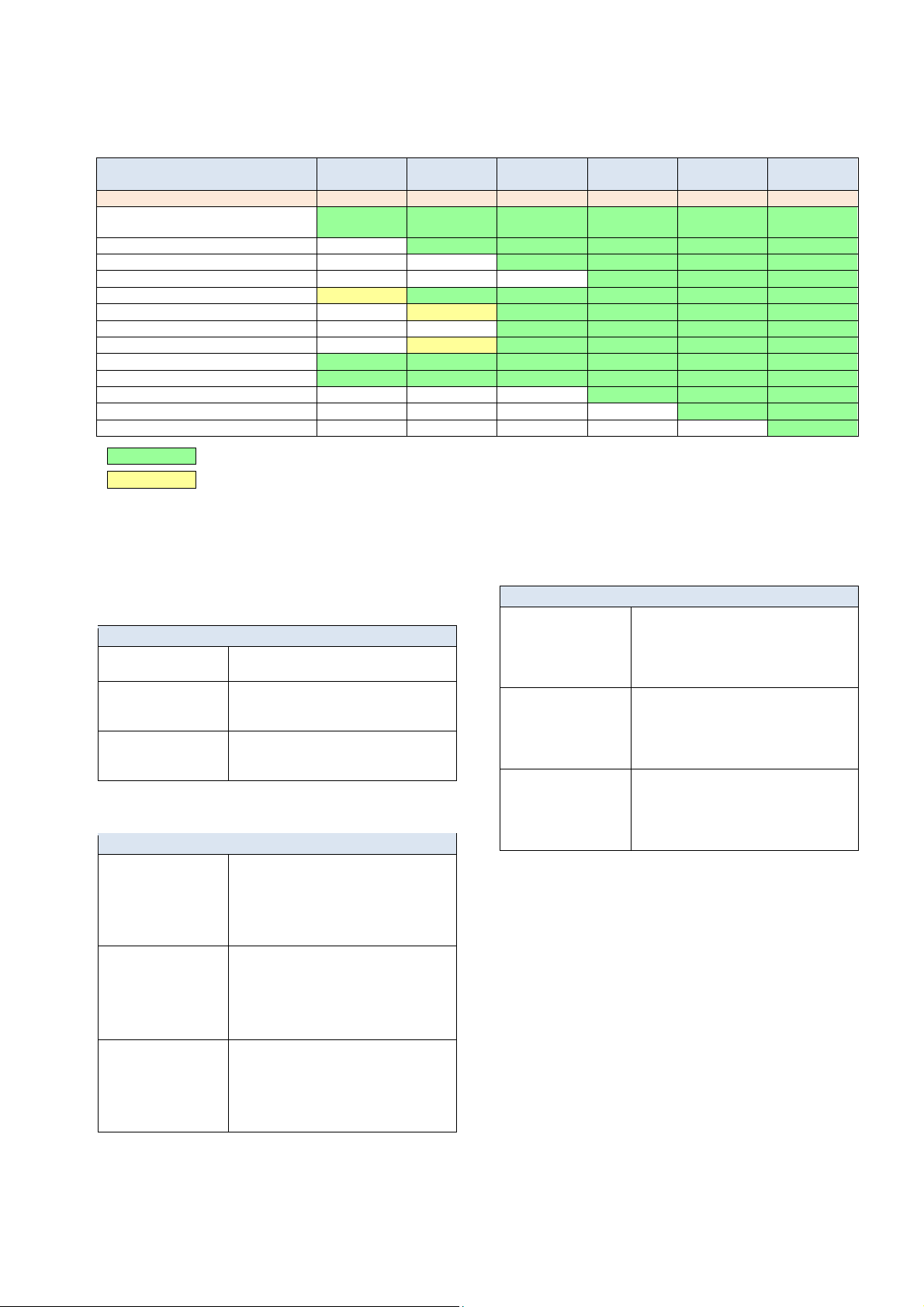
21
User management
21.3 Overview of user rights
▼ Function
User level ►
Guest
(Level 0)
Customer
(Level 1)
Customer
(Level 2)
Service
(Level 3)
Master
(Level 4)
Factory
(Level 5)
Standard access code - 1234 9876 8642 xxxx xxxx
Complete menu navigation
"See everything - change nothing"
Setting uncritical parameters
Setting parameters critical to function
Setting parameters relevant to safety
Call-up mode menu
1-point calibration
2-point calibration
Manual dosing
Acknowledge acoustic alarm
Acknowledge alarms
Acknowledge service messages
Master (level 4) - Special functions
Factory (level 5) - Special functions
Function area permitted for the corresponding user level
Function area not permitted for the corresponding user level, but can be released by system operator.
21.4 Configure access rights for remote access
In the menu Configure access rights for remote access, multiple
settings regarding access rights in remote access can be made.
It can be defined whether remote access is allowed or not for various
functions. It is possible to configure the following settings:
Release of remote access
Inactive Remote access to the corresponding function is
Local network Remote access to the corresponding function is
Local network & Web Remote access to the corresponding function is
Remote access can be released or blocked for the following functions:
Sub-menu Configure access rights for remote access
Allow remote access mode
menu
Allow remote access
calibration
Allow
remote access
manual dosing
blocked.
released on the local network only, but not on
the Internet (Web).
released both the local network and on the
Internet (Web).
Release of mode menu for remote access
Under certain circumstances, critical functions
can be turned on and off accidentally during
remote access to the Mode menu. That is why
the default setting blocks remote access to the
Mode menu.
In general, calibration has to be performed onsite. That is why the default configuration blocks
remote access to calibration.
If needed, however, calibration can be released
for remote access if, for example, a mobile
device is going to be used on-site.
In general, manual dosing has to be performed
on-site. That is why the default setting blocks
remote access to the manual dosing. If needed,
however, calibration can be released for remote
access if, for example, a mobile device is going
to be used on-site.
21.5 Adjust requisite
user level for functions
In the menu Adjust requisite user level for functions, the requisite user
level for access to various functions can be adjusted as needed:
Sub-menu Adjust requisite user level for functions
User level
for Mode menu
User level
for 1-point calibration
User level
for manual dosing
Requisite user level for access to the Mode
menu.
Potential settings:
• Customer (level 0) ( no login!)
• Customer (level 1)
Requisite user level for
1-point calibration.
Potential settings:
• Customer (level 1)
• Customer (level 2)
Requisite user level for
manual dosing.
Potential settings:
• Customer (level 1)
• Customer (level 2)
21.6 User login with access code
Most parameter changes and access to some menus require
authentication with a certain user level. If authentication is required,
then the menu User login will appear automatically.
In this menu, first chose the user with the access code you would like
to use for login. Then enter the correct access code for the selected
user. If the access code entered is correct, then you'll be granted
access to the secure area.
• After successful login, the corresponding user level will remain
valid until you return to home view; or, after several minutes the
screen is returned to home view automatically.
• No new login is necessary for as long as the user level is still
valid. The menu User login will only appear again for accessing
functions requiring a higher user level.
User Manual PoolManager® 51
Page 52
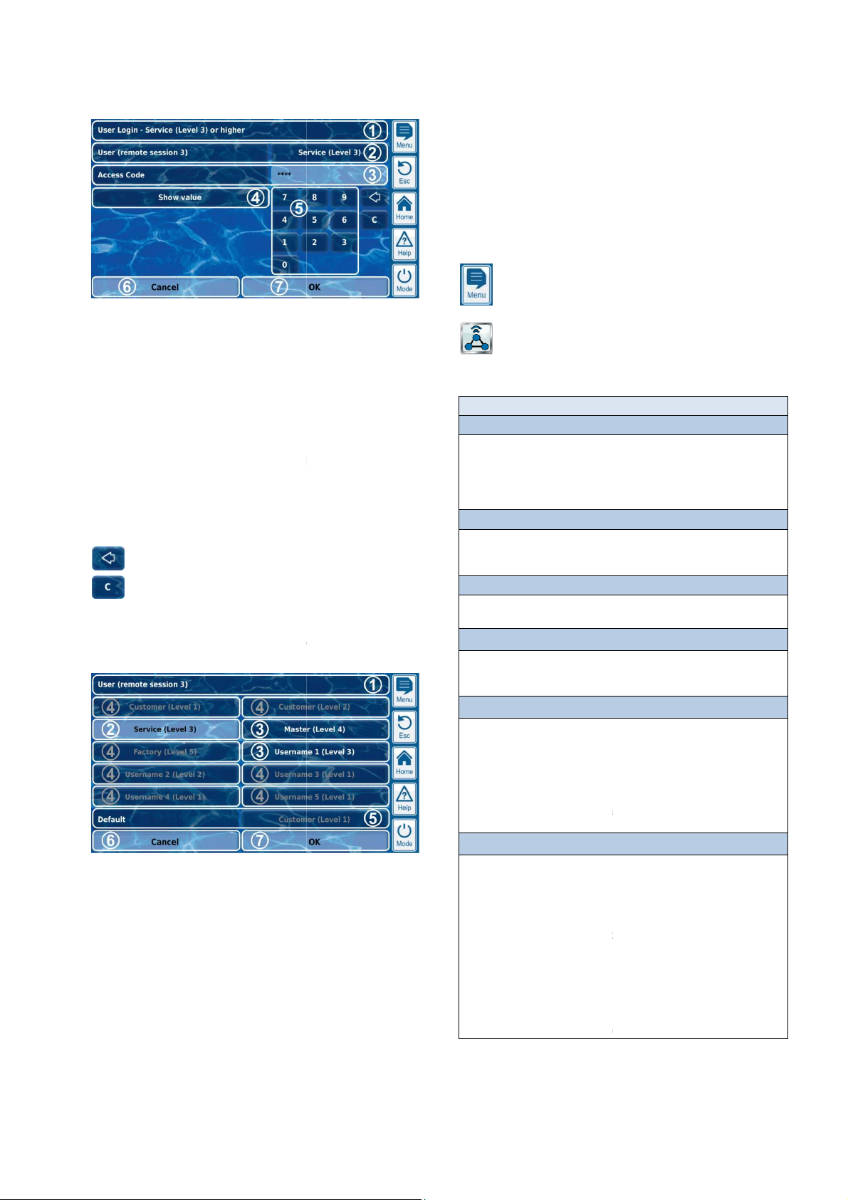
22
minimum user level for the desired function
last user used is displayed if
Otherwise, the standard user is displayed with the requisite
The default setting is for the entered code to be masked
(****). This button can be used to display the actual
OK confirms the entries. Once authentication has been
successful, you'll be forwarded to the desired menu.
If the user selection screen is opened in the menu User login (2), then
Currently selected user (white background)
Further potential users for the desired function
Users to whom access to the desired function is not
Cancel will close the selection screen.
OK will confirm the selection and return to the menu
There may be various causes for a user not being selectable and
therefore being displayed in grey lettering:
for the desired function
The user level is higher than that of the current user for remote
Communication & interfaces
Communication & interfaces
Communication & interfaces
menus with the following
Communication & interfaces
menu provides import and export functions for various data:
Individual background images (import)
menu, the network settings (IP settings, IP = Internet protocol) are
made for remote access from the local network.
the local network.
menu configures the options for sending e
menu configures the CAN bus for the connection of future add
boxes). Please refer to the separate documentation for the
corresponding feature box for more information.
menu configures the optional RS
as an optional supplemental module
RS485 CONVERTER (Art. no. 127012)
485 interfaces facilitates access to PoolManager
(alarms, etc.). For more details, please refer to the separate documentation
(Art. no. 127012).
menu configures the PoolManager
outputs are available as an optional supplemental module
in module with 4 power outputs):
20MA (Art. no. 127011)
The power outputs can be used for the following functions:
Transmitting current measured values (pH, mV,
20mA (for videographic recorders, remote displays, building
(e.g. variable filter pumps, salt electrolysis systems)
For more details, please refer to the separate documentation for
(Art. no. 127011).
Communication & interfaces
The menu User login is set up as follows:
• The user level is too low
• Only for remote access:
access
Menu title indicating the requisite
1
2 Selection of the desired user.
The default setting is that the
that user's level is sufficiently high.
minimum user level.
3 Enter access code.
4
5 Number keypad for code entry.
6 Cancel will close the entry screen.
7
Delete the last number
Delete the entire access code
21.6.1 User selection
it will be displayed as follows:
22
The menu
is called up as follows:
Menu hotkey
The menu contains multiple subconfiguration options:
code.
Menu
Data import & export
This sub-
• Measured value graph (export)
• Event log (export)
•
See section Data import & export
Network (IP) configuration
In this sub-
See section Remote access to
E-mail configuration
This subSee section E-mail functions.
CAN bus interface
This subboxes (feature
RS-485 data bus interface
This subPoolManager® data.
The RS-485 interface is available
(internal plug-in module).
PM5-
The RS-
-mails via PoolManager®.
-485 interface for access to
®
-on
data and statuses
Menu title, with indication of session
1
(Local or remote access)
2
3
(White lettering)
4
granted (grey lettering)
5 Default user
6
7
User login.
User Manual PoolManager®
for the PM5-RS485 CONVERTER
Current outputs 0/4-20mA
This sub20mA.
These power
(internal plug-
PM5-SA4 CONVERTER 0/4-
•
0/4management systems)
• Triggering external systems
SA4 CONVERTER 0/4-20MA
®
optional power outputs 0/4-
temp.) as power signal
the PM5-
52
Page 53
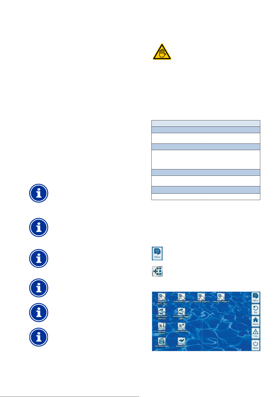
23
provides functions for importing and
Download measured value graphs from a device
Save measured value graphs to USB stick
mail transmission of measured value graph
mail recipients)
In order to use the export functions for the measured value
graph, automatic measured value grap
activated in advance. This automatically saves daily
measured value graphs in PoolManager
Load background image to unit device
Load background image from USB stick
USB memory stick data import & export
Save measured value graphs to USB stick
USB stick
To export measured value graphs, a start date and
an end date have to be selected first. This will then
export the measured value graphs available for the
individual background images
Load individual background images from USB stick
The images on the USB stick have to be in a sub
pm5_image and meet the requirements
measured value graph to USB stick
Measured value graphs are stored to a USB stick
Event logs are stored to a USB stick in the
Inserting and removing a USB
Requisite user qualification:
mail functions, especially accounts for
mail (SMTP) may only be performed by an IT
SPECIALIST as defined in the chapter
has a connection to the Internet (see
, then it has the capacity to send e
The following functions can then be realised:
Automatic transmission of measured value graphs
mail functions are configured in the menu
There, the following options are available:
mail addresses
menu can be used to configure up to three recipient e
addresses and to activate or deactivate them individually.
mails (SMTP)
-
mails. To do so, you'll need an SMTP account with a corresponding e
provider (SMTP = simple mail transfer protocol) and need to have the
corresponding access information ready.
menu to configure
mail to the active e
provides comprehensive supplemental functions for
intelligent control of numerous systems in the swimming pool
Supplemental functions
is realised as an icon menu. Every
function is represented by its own icon.
functions are described in detail in the following
User
Add-onfunctions
22.1 Data import and export
The menu Data import and export
exporting various data:
• Export measured value graph
•
(in remote access from a PC)
•
• Automatic e-
(every 1...7 days to up to 3 e-
•
• Export event log
• Download event log from a device
(in remote access from a PC)
• Save event log to USB stick
• Load individual background images
•
(in remote access from a PC)
•
•
•
• Save event log to USB stick
• Load background image from
INFO
Measured value graph export
•
h saving has to be
®
for later export.
22.2 E-mail functions
IT SPECIALIST
Setting up esending e-
qualification.
If PoolManager®
from the Internet)
• Alarm e-mails
•
E-
Menu E-mail configuration
Configuration of recipient e-
This sub-
Account for sending e-
In this sub-menu, the account is set
e-
Alarm e-mails
You can use this subreceive alarm e-mails.
Send test e-mail
This function sends a test e-
Remote access
-mails.
E-mail configuration.
-mail
up that PoolManager® uses for sending
-mail
the cases in which recipients will
-mail recipients.
time frame indicated.
INFO
Requirements for
• Image size 800x480 pixels
• JPEG format
• Max. 300kB
23 Add-onfunctions
PoolManager®
environment.
You can call up the menu
follows:
at any time as
INFO
Menu hotkey
•
directory \
named.
INFO
Save
•
in the directory \pm5_graph
-
Add-on functions
The menu Add-on functions
individual add-on
INFO
Save event log to USB stick
•
directory \pm5_graph
INFO
memory stick
See chapter USB interface.
The individual add-on
sections.
User Manual PoolManager®
53
Page 54
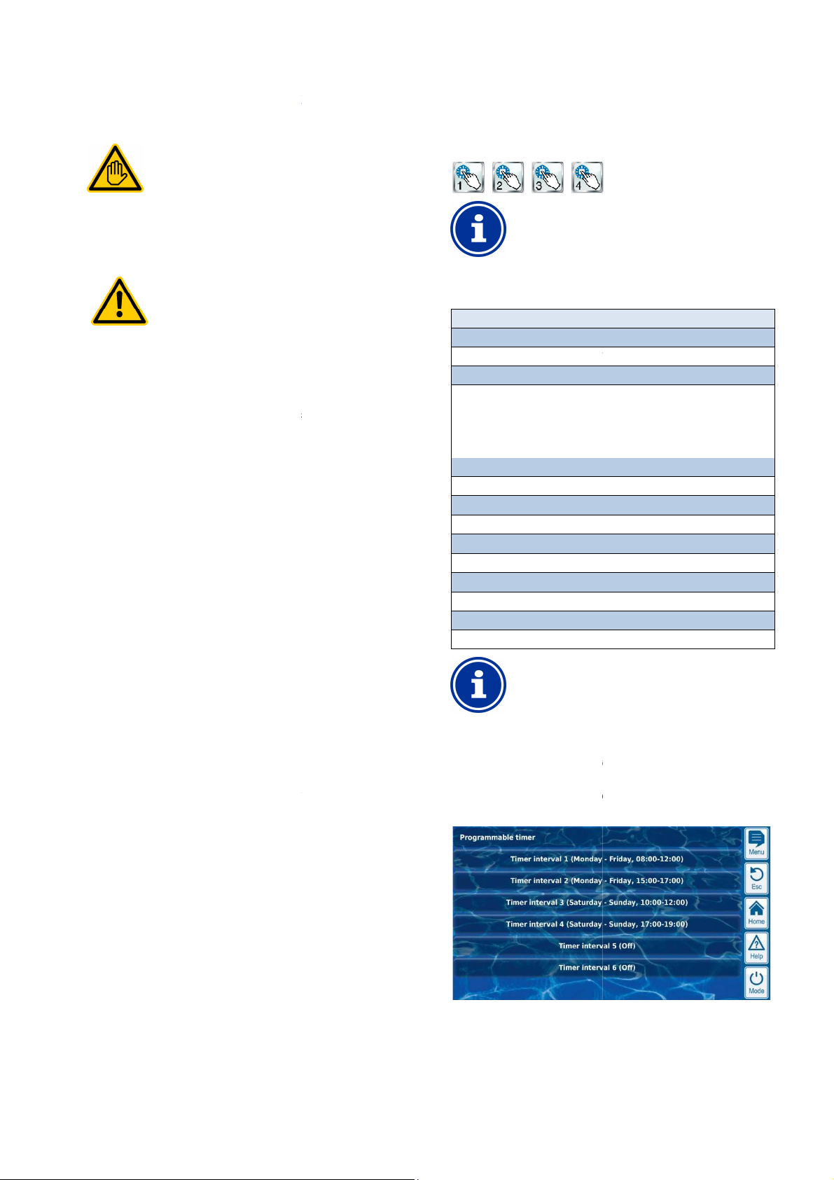
24
outputs (4x)
Connection, configuration, and start
switch outputs may only be performed by a TRAINED
SPECIALIST or an ELECTRICAL SPECIALIST as
User qualification.
Universal switch outputs can fundamentally be used for
the widest variety of functions. Depending upon the
application, switching processes or the switched
Potential consequence: Death or the g
degree of injury, heavy material damage.
The use of universal switch outputs is expressly
PROHIBITED for all applications in which the
safety of persons, animals, and property is not
completely guaranteed at all times and under all
is particularly prohibited to connect sauna ovens
without the corresponding safety
It is particularly prohibited to open and close
swimming pool covers without the corresponding
safety precautions (danger of drowning!)
is exclusively in the system operator's
The system operator must perform
analysis for every application planned.
The device manufacturer disclaims all liability.
provides four universal switch out
intelligent and highly flexible control of water attractions and other
There is a relay switch with the corresponding connection terminal
features of the universal switch outputs are:
Operation optionally as potential free switch or as 230V~
Interval operation possible (turning on and off periodically)
al block in the event of missing flow
Potential block dependent upon the filter pump's operation
push button
Remote access can be individually released or
Display in the Mode menu can be individually released or blocked
up of universal
precautions (fire
a hazard
The configuration menus for each individual switch output are set up
Designation of universal switch outputs
In all menus in which the universal switch outputs
appear, the switch output designation you entered will
Waterfall)
The following settings are available:
Configuration menu for universal switch outputs
Entry of the freely selectable name for the switch output.
Off (Switch output used, but turned off)
Switches on the universal switch output for the programmed time.
Program switch on and off times for different days of the week.
ty settings for the switch output.
Allocation of a relay switch output
A universal switch output can only be activated if you
have allocated a relay switch output to it beforehand.
provides 6 freely programmable time intervals for each
The time intervals are displayed in the menu in an easy
manner with programmed weekdays and times:
Universal switch outputs (4x)
24 Universal switch
24.1 Safety information
Requisite user qualification:
TRAINED SPECIALIST or
ELECTRICAL SPECIALIST
defined in the chapter
HAZARD!
Hazardous applications
function could produce hazards.
•
circumstances.
• It
hazard!)
•
• Safety
sphere of responsibility.
•
•
24.2 Overview
PoolManager®
functions in the swimming pool environment.
assigned to each switch output.
The particular
•
• Freely selectable names
• Flexibly programmable timers
for each switch output
•
• Potenti
•
• Potential block via an input
• Potential block via another output
• Link with an external switch or
•
individual switch output
•
for each individual switch output
-
ravest
puts that facilitate
s
blocked for each
-output
24.3 Configuration menu
identically.
They are called up via the icons
INFO
Name
Mode of operation
Selection of operating mode:
• Inactive (Switch output not used)
•
• On
• Timer
Timer function
Programming timers.
Time function switch on time
Programmable timer
Basic configuration
Basic settings for the switch output.
Safety settings
Safe
be indicated (e.g.
INFO
24.3.1 Timer function
This menu
switch output.
-to-follow
User Manual PoolManager®
54
Page 55
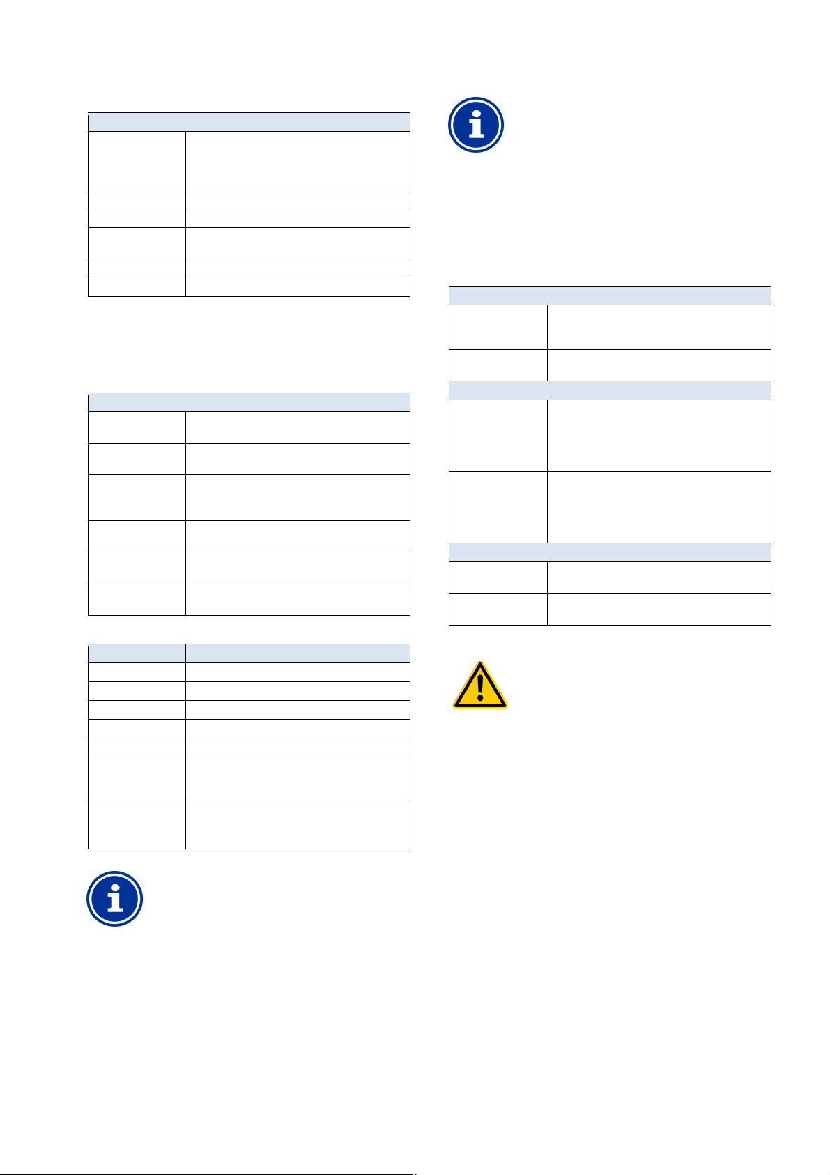
24
the relay outputs OUT1 ... OUT4, the terminal block
number is indicated directly in the menu. This is the
The relay output OUT4 is designed as a toggle switch.
block [31] is turned on.
All other switch outputs are designed as simple on/off
Depending on the installation, hazards may be yielded
remote
Release of remote access to universal switch
outputs is expressly PROHIBITED for all
applications in which the safety of persons,
ot completely guaranteed
at all times and under all circumstances; especially
Safety is exclusively in the system operator's
Universal switch outputs (4x)
The following settings are possible for each of the 6 time intervals:
Sub-menu Programable timer (1..6)
Days of week Selection of one or multiple weekdays on which the
Switch-on time Time at which switch-on occurs.
Switch-off time Time at which switch-off occurs
Interval mode Activation of interval operation
Switch-on interval Switch-on duration for interval operation.
Switch-off interval Switch-off duration for interval operation.
time interval should be active.
If no weekday is activated, then the entire time
interval is inactive.
(Periodic switching on and off)
24.3.2 Basic configuration
The menu Basic configuration is used to configure the basic settings
for a switch output. This is generally done once upon placing a switch
output into operation.
The following settings are available:
Sub-menu Basic configuration
Relay output Relay switch output used for the universal switch
Block in the event of
missing flow
Blocking by filter
pump operating mode
Blocking via input. Yes The output is turned off if the selected input is
Blocking by another
output
External switch or
push buttons
For each relay switch output, the following settings are available:
Setting Description
None The universal witch output is not used.
OUT 1 [26] Relay switch output OUT 1 [terminal block 26]
OUT 2 [27] Relay switch output OUT 2 [terminal block 27]
OUT 3 [30] Relay switch output OUT 3 [terminal block 30]
OUT 4 [31] Relay switch output OUT 4 [terminal block 31]
pH+ [22] Dosage relay pH + [terminal block 22]
pH- [21] Dosage relay pH + [terminal block 21]
output.
Yes Output is turned off if flow signal is missing.
Yes The output is turned off if the filter pump is in
the corresponding operating mode.
Prerequisite: PoolManager® controls the filter pump.
in the state indicated.
Yes The output is turned off if the other output
selected is in the state indicated.
See External switch or push button.
Can only be used
if no pH+ dosage is used.
Can only be used
if no pH- dosage is used.
INFO
Terminal block indication
For
number in brackets, e.g. [26] for OUT1.
INFO
Toggle switch OUT4
When active (on), terminal
When inactive (off), terminal block [32] is turned on.
switches.
24.3.2.1 External switch or push buttons
Each switch output can be linked with an external switch or device,
which facilitates turning the function on or off manually.
The following settings can be configured:
Sub-menu External switch or device
External switch input Selection of an input to which the external switch is
Type of external
switch
For on/off switch only
External switch Defines the operating mode when external
External switch off Defines the operating mode when external
For push buttons only
Function of external
push buttons
Timer for
external push button
24.3.3 Security settings
connected
(IN 1 [6] / IN 2 [7] / IN 3 [8] / IN 4 [9] / none)
On/off switch or push button.
switch is turned on:
• Output ON
• Output AUTO,
(Operating mode controlled by PoolManager®)
switch is turned off:
• Output OFF
• Output AUTO,
(Operating mode controlled by PoolManager®)
Start timer or
Output on/off
Switch-on duration
(For the function Start timer)
HAZARD!
Hazard via remote access
by universal switch outputs, particularly via
access.
Potential consequence: Death or the gravest
degree of injury, heavy material damage.
•
animals, and property is n
for remote access.
•
sphere of responsibility.
• The device manufacturer disclaims all liability.
User Manual PoolManager® 55
Page 56
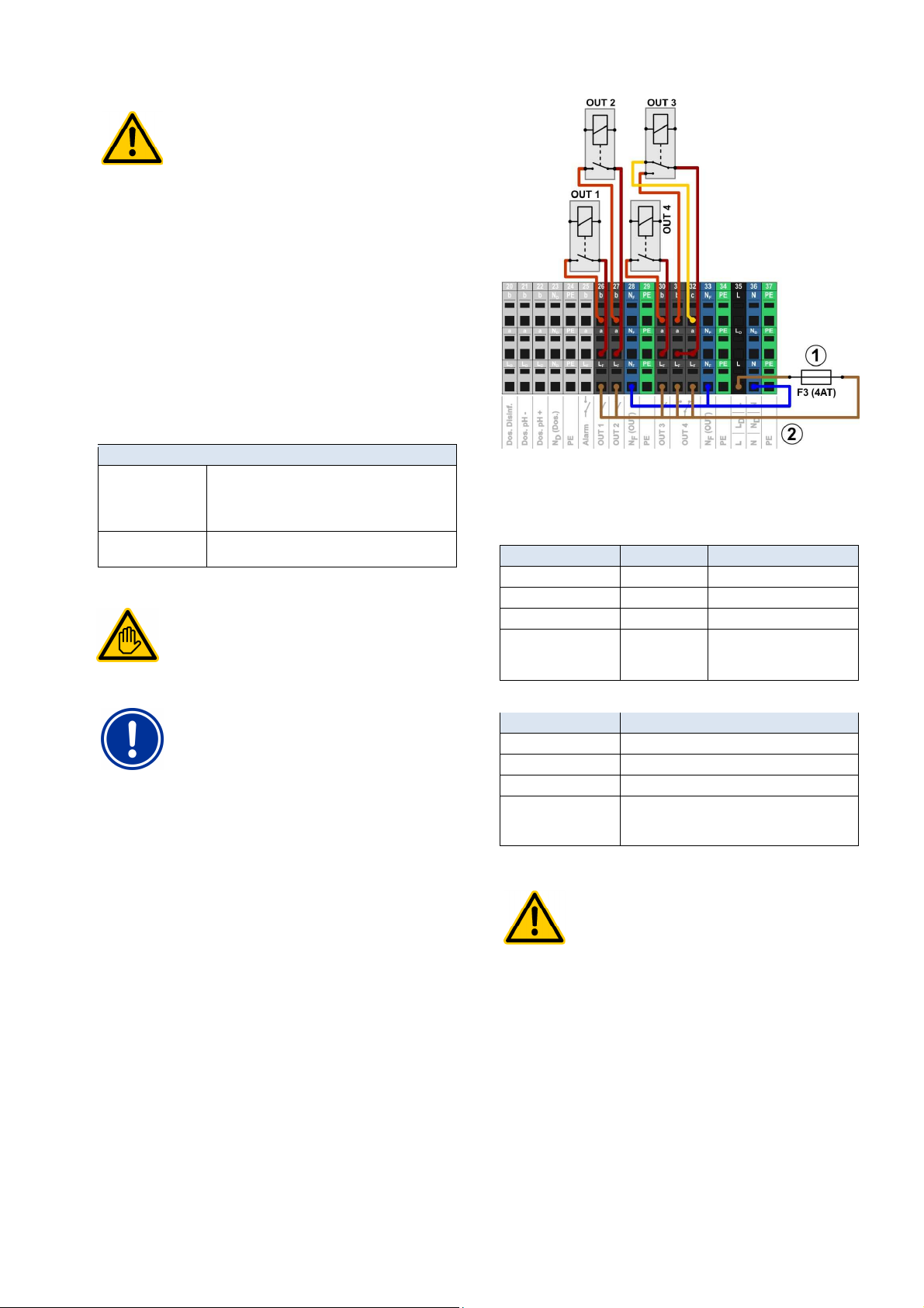
24
Switch outputs can be switched quickly and easily in
Mode menu. This also yields the hazard of an
isplay of universal switch outputs in Mode
menu is expressly PROHIBITED for all applications
in which the safety of persons, animals, and
property is not completely guaranteed at all times
and under all circumstances; especially for remote
ly in the case of potential
Safety is exclusively in the system operator's
Electrical connection of universal switch outputs may
SPECIALIST
Observe the maximum permissible currents for each
ay switch output (max. 4A) and for the sum
of all relay switch outputs being used in 230V~ (in sum,
to centre contact
ons is
Ensure that the permissible total current is never
If high currents are needed, then the voltage supply
230V~ Power
Universal switch outputs (4x)
HAZARD!
Hazard from erroneous operation in Mode menu
erroneous operation (switching accidentally)
Potential consequence: Death or the gravest
degree of injury, heavy material damage.
• The d
access; especial
erroneous operation in Mode menu.
•
sphere of responsibility.
The following security settings are available:
Sub-menu Security settings
Allow remote access Potential settings:
Display in
Mode menu
24.4 Electrical connection
• The device manufacturer disclaims all liability.
• Inactive
• Local network
• Local network & Web
Yes / no
Requisite user qualification:
ELECTRICAL SPECIALIST
only be performed by an ELECTRICAL
as defined in the chapter User qualification.
IMPORTANT NOTICE!
Observe maximum flows
individual rel
max. 4A)
Please also refer to the Chapter 230V~ Power supply.
The following figure shows the internal wiring for relay switch outputs
OUT1...OUT4, which can be used for universal switch outputs. All
connections shown are run internally as conductor paths.
1 Fuse 4AT
2 230V~ phase LF for the add-on functions
The following terminal blocks are allocated to the relay switch outputs:
Each terminal block is set up as follows:
24.4.1 Connection variations
(secured with 4A)
Relay switch output Terminal block Function
OUT 1 26 NO switch
OUT 2 27 NO switch
OUT 3 30 NO switch
OUT 4 31 and 32 Toggle switch
c = Resting contact
b = Working contact
Terminal Function
b Working contact
c Rest contact (for OUT 4 only)
a Centre contact
LF Supply phase 230VAC for add-on functions.
Can be bridged to the centre contact if needed in
order to control 230VAC devices.
HAZARD!
Permissible total current exceeded
in 230V~ applications
For all 230V~ switch outputs using PoolManager
internal 230V~ supply (bridge from LF
a), the total current may not exceed 4A in total.
The phase LF for supplying the add-on functi
secured with 4AT (F3 OUT).
Potential consequence:
Burning of conductor paths in PoolManager®
•
exceeded.
•
has to be external.
• Please also refer to the Chapter
supply.
®
User Manual PoolManager® 56
Page 57
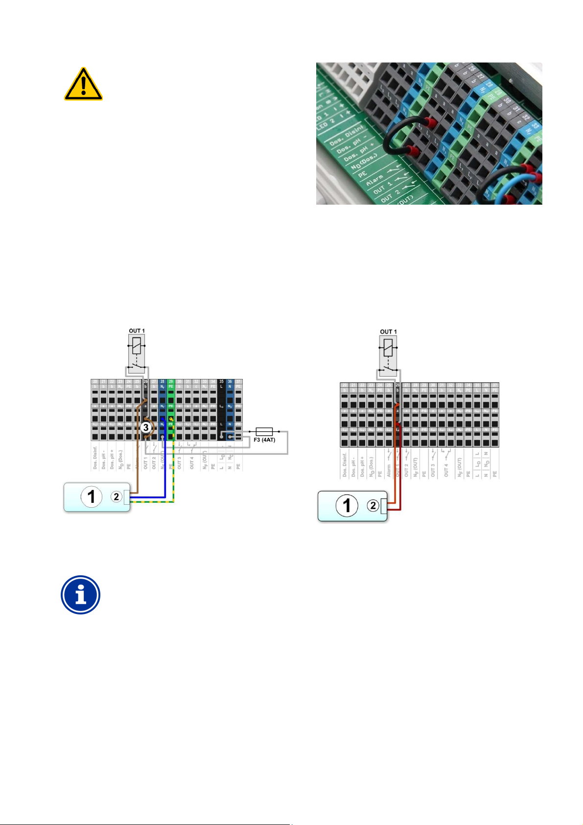
24
The system current may not exceed 4A per switch
output. The maximal permissible switching contact
Ensure that permissible current and permissible
If applicable, secure the electrical circuits externally
rrents or voltages are needed, then an
The controlled external system's neutral conductor N
protective earth PE can be connected to the
and PE as
Universal switch outputs (4x)
HAZARD!
Exceeding the permissible switching current
or the permissible contact voltage
voltages are 230V~ and 30V DC.
Potential consequence:
Burning of conductor paths in PoolManager®
•
voltage are never exceeded.
•
in accordance with applicable stipulations.
• If higher cu
external circuit breaker has to be used.
24.4.1.1 230VAC unit control
A 230V~ unit is connected between neutral conductor N (blue) and
phase L (brown) of the power supply, between which there is a voltage
of 230V~ (AC voltage). Additionally, there is generally also a protective
earth connection (yellow/green).
Should a unit of this kind be controlled via a PoolManager® universal
switch output, then it has to be connected as follows (Example for
switch output OUT 1):
Wire bridge in the terminal box from phase LF to centre relay contact a
24.4.1.2 Control of unit with
potential free control input
Some systems have a potential free control input. This can be
connected directly to the PoolManager® switch output.
If control input of this kind is available, then it should always be used
whenever possible instead of turning the external system's power
supply on and off.
The following figure shows how the connection of an external system
with potential free control input to the switch output OUT 1:
1 External system to be controlled
2 External systems 230V~ power supply
3 Wire bridge in the terminal box from phase LF to centre
relay contact a
INFO
Connection of neutral conductor N and PE
and
terminal blocks intended for the purpose NF
shown in the figure.
1 External system to be controlled
2 External system's potential free control input
User Manual PoolManager® 57
Page 58
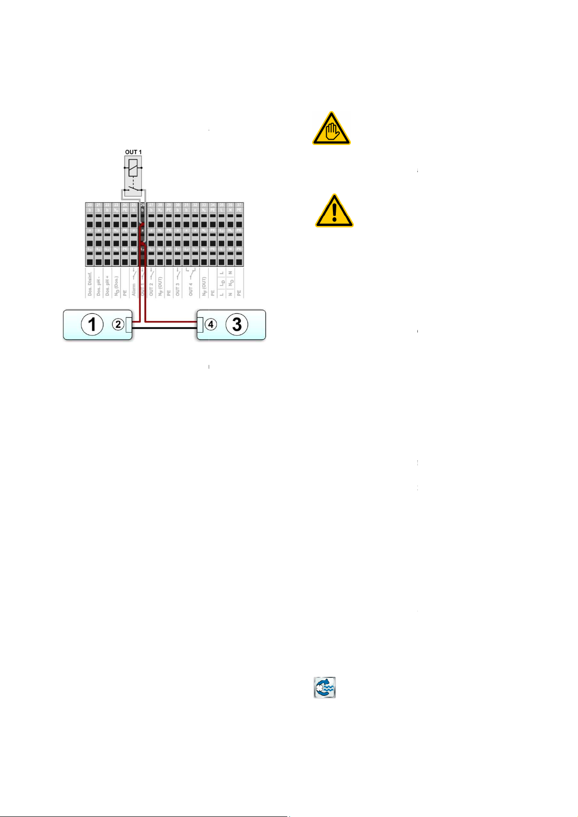
25
For external systems with their own power supply (AC or DC), the
power supply can be turned on and off via PoolManager
The following figure schematically shows an application example for
External system's voltage supply input
External system's voltage supply output
Lifespan of relay switching contacts
Depending on application, the lifespan of a relay
In general, the lifespan of a relay contact is reduced by high circuit
The following guideline values can be used for orientation:
Filter pump control
Requisite user qualification:
TRAINED SPECIALIST or
ELECTRICAL SPECIALIST
Connection, configuration, and start
control may only be performed by a TRAINED
ALIST or an ELECTRICAL SPECIALIST as
defined in the chapter
Hazard from turning on filter pump
Turning on a filter pump can yield hazards for
swimming guests
(e.g. due to current or suction effects).
Potential consequence:
degree of injury, heavy material damage.
Turning on a filter pump is expressly PROHIBITED
for all applications in which the safety of persons,
animals, and property is not completely guaranteed
at all times and under all circumstances.
Safety is exclusively in the system operator's
sphere of responsibility.
The device manufacturer disclaims all liability.
offers a triggering option for filter pumps. Conventional
filter pumps are simply turned on and off. Suitable
can additionally be set into three different operating modes:
(Energy saving mode, e.g. for night reduction)
(Increase pump output, e.g. for filter rinsing,
attractions, or solar power operation)
filter pump control additionally offers the following
Multiple flexibly programmable timers
Free configurable blocking of dosage (pH and disinfection)
p operating mode
Linking of each filter pump operating mode with an external switch
Flexible allocation of up to three relay switch outputs for the filter
pump's various operating modes
Operation of relay switch outputs optionally as potenti
Alternative filter pump triggering via a power output 0/4
The configuration menu for filter pump control is called up with the
up of filter pump
Filter pump control
24.4.1.3 Control of unit with
external voltage supply
output.
switch output OUT 1.
1 External system to be controlled
2
External system's voltage supply
3
(AC or DC)
4
24.4.2
may be limited.
currents.
• 230V~, 0.5A, resistive load
Lifespan > 1,000,000 switches
• 230V~, 4A, resistive load
Lifespan > 300,000 switches
switching contact
®
switch
25
25.1 Safety information
SPECI
HAZARD!
•
•
•
25.2 Overview
PoolManager®
• Normal operation
(Normal filter operation)
• Reduced output
• Increased output
PoolManager®
options:
•
•
depending on the filter pum
•
or push button
•
•
switch or as 230V~-output
•
(optional)
-
User qualification.
Death or the gravest
variable filter pumps
connecting water
al free
-20mA
25.3 Menu Filter pump
following icon:
Filter pump
User Manual PoolManager®
58
Page 59
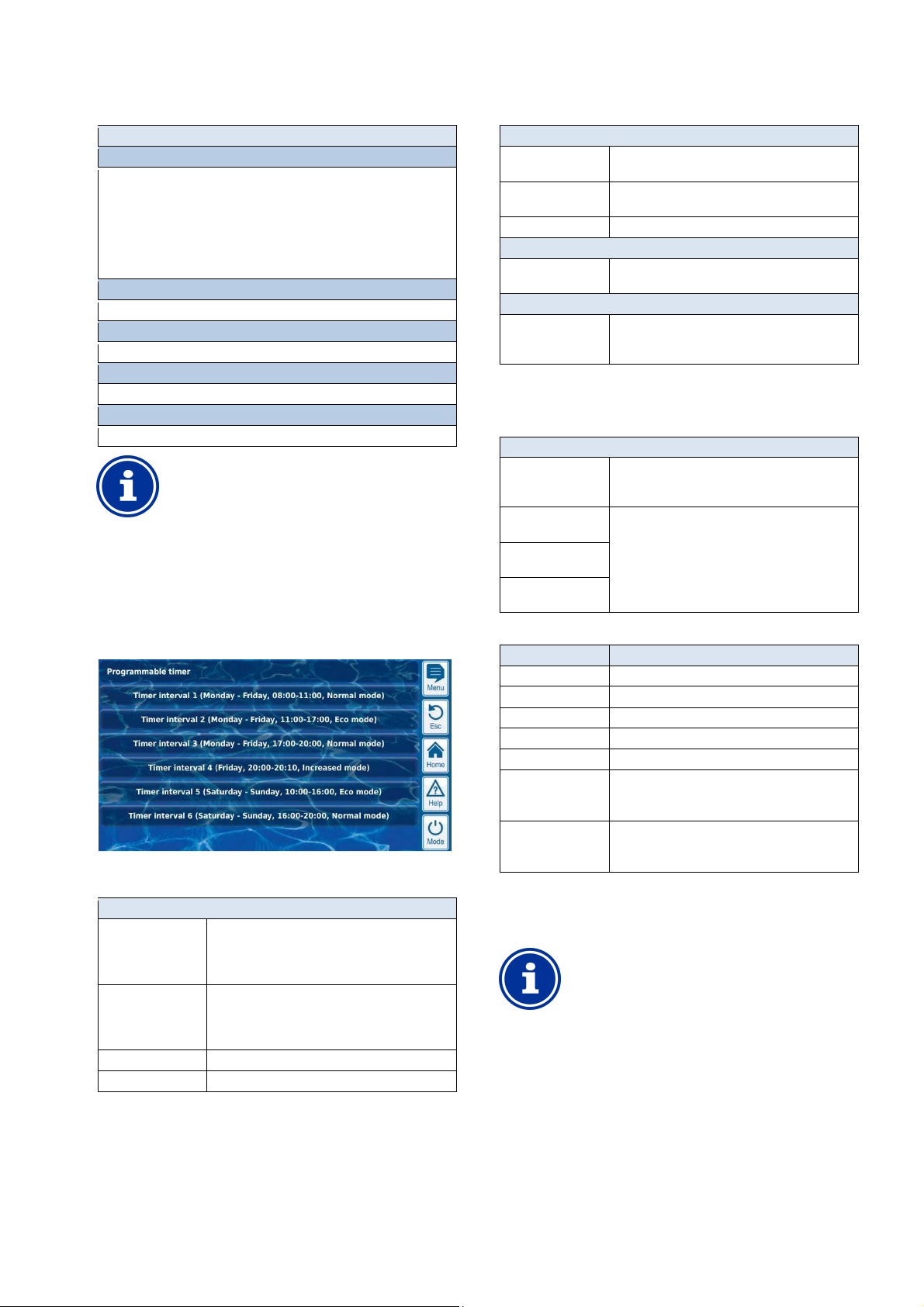
25
operating mode can only be activated if you have
in module is
Filter pump control
The following settings are available:
Menu Filter pump
Filter pump mode of operation
Selection of operating mode:
• Inactive (Filter pump control not used)
• Filter pump off
• Normal operation
• Reduced output
• Increased output
• Timer
Programmable timer
Programming timers.
Basic configuration
Basic settings for filter pump control.
Dosing settings
Determine dosing behaviour for different filter pump operation modes.
Safety settings
Security settings for filter pump control.
INFO
Allocation of relay switch outputs
An
allocated a relay switch output to it beforehand.
25.3.1 Programmable timer
This menu provides 6 programmable time intervals for filter pump
control.
The time intervals are displayed in the menu in an easy-to-follow
manner with programmed weekdays and times and with the filter
pump's operating mode:
The following settings are possible for each of the 6 time intervals:
Sub-menu Timer interval (1..6)
Filter pump operating
mode
Days of week Selection of one or multiple weekdays on which the
Switch-on time Time at which switch-on occurs.
Switch-off time Time at which switch-off occurs
The desired operating mode for this time interval:
• Normal operation
• Reduced output
• Increased output
time interval should be active.
If no weekday is activated, then the entire time
interval is inactive.
The following settings are available:
Sub-menu Basic configuration
Filter pump control
interface
Allocation of inputs
Relay trigger or
4x power output 0/4-20mA
See universal switch output.
and outputs
Dosage blocking See Dosing settings
For Relay trigger only
Allocation of
See Allocation of inputs and outputs.
inputs and outputs
Only for power output 0/4-20mA
Configuration power
output
See Configuration power output
0/4-20mA.
0/4-20mA
25.3.2.1 Allocation of inputs and outputs
For Relay trigger only.
This menu allocates the relay switch outputs for filter pump control.
Sub-menu Allocation of inputs and outputs
Relay output 'Filter
pump on/off'
Relay switch output for turning on the filter pump (for
conventional filter pumps or as superordinate on/off
switch for variable filter pumps).
Relay output 'normal
mode'
Relay output
Relay switch outputs for activating the various
operating modes for variable filter pumps.
Note: Not all three operating modes have to be used.
'Eco mode'
Relay output
'Increased output'
For each relay switch output, the following settings are available:
Setting Description
None The corresponding function is not used.
OUT 1 [26] Relay switch output OUT 1 [terminal block 26]
OUT 2 [27] Relay switch output OUT 2 [terminal block 27]
OUT 3 [30] Relay switch output OUT 3 [terminal block 30]
OUT 4 [31] Relay switch output OUT 4 [terminal block 31]
pH+ [22] Dosage relay pH + [terminal block 22]
Can only be used
if no pH+ dosage is used.
pH- [21] Dosage relay pH - [terminal block 21]
Can only be used
if no pH- dosage is used.
25.3.2.2 Configuration power output 0/4-20mA
Only for triggering with Power output 0/4-20mA.
This menu configures the power output for the filter pump control.
INFO
Plug-in module PM5-SA4 needed
To trigger the filter pump via a power output
04/-20mA, the following optional plugneeded:
PM5-SA4 CONVERTER 0/4-20MA (Art. no. 127011)
25.3.2 Basic configuration
The menu Basic configuration is used to configure the basic settings
for a switch output. This is generally done once upon placing into
operation.
User Manual PoolManager® 59
Page 60
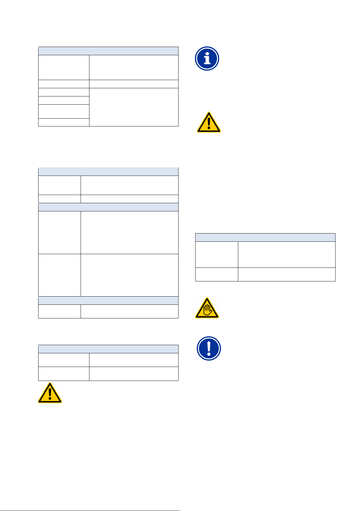
25
When dosing in water with very little circulation,
poisonous gaseous chlorine can be produced when
Only active dosing for reduced output if good
circulation and quick transportation of the dosed
lly barely
affected by flow. Therefore, it is not absolutely
For maximum safety, however, blocking is
filter pump in remote access can yield
Remote access to filter pump control is expressly
or all applications in which the
safety of persons, animals, and property is not
completely guaranteed at all times and under all
Safety is exclusively in the system operator's
Electrical connection of filter pump control may only be
performed by an ELECTRICAL SPECIALIST as
each
individual relay switch output (max. 4A) and for the sum
of all relay switch outputs being used in 230V~ (in sum,
Filter pump control
Configuration power output 0/4-20mA
Relay output 'Filter pump
on/off'
Power output used Power output for triggering the filter pump.
Power for pump off Entry of currents in [mA], which the power
Power for reduced output
Power for normal
operation
Power for increased output
Relay switch output for turning on the filter pump
(for conventional filter pumps or as
superordinate on/off switch for variable filter
pumps).
output used sets for the various operating
modes.
25.3.2.3 External switches
The filter pump control can be linked with up to three external switches
or push buttons that facilitate turning on/off manually or activating a
certain operating mode.
The following settings can be configured:
Sub-menus External switches
External switch
1 / 2 / 3
Type of ext. switch On/off switch or pushbutton
For on/off switch only
External switch on Defines the operating mode when external
External switch off Defines the operating mode when external
For devices only
Function of external
device
Selection of an input to which the external switch is
connected
(IN 1 [6] / IN 2 [7] / IN 3 [8] / IN 4 [9] / none)
switch is turned on:
• Filter pump off
• Normal operation / reduced output /
increased output
• Filter pump AUTO,
(Operating mode controlled by PoolManager®)
switch is turned off:
• Filter pump off
• Normal operation / reduced output /
increased output
• Filter pump AUTO,
(Operating mode controlled by PoolManager®)
Toggle off / normal / off / ... or
toggle off / low / normal / high / off / ...
25.3.2.4 Dosage blocking
Here, you can defined the operating modes in which dosing is blocked
for pH control and disinfection.
Sub-menu Dosage blocking
Dosage blocked for
reduced output
Dosage blocked for
increased output
Yes / no
Yes / no
HAZARD!
Gaseous chlorine produced from dosing
with too little water circulation
ChloriLiquid and pH minus meet.
Potential consequence: Death or the gravest
degree of injury,
heavy material damage.
•
INFO
Dosage for increased output
pH and redox measurement are genera
necessary to block dosing for increased output.
25.3.3 Safety settings
recommended.
HAZARD!
Hazard via remote access to
filter pump control
Turning on a
hazards for swimming guests
(e.g. due to current or suction effects).
Potential consequence: Death or the gravest
degree of injury, heavy material damage.
•
PROHIBITED f
circumstances.
•
sphere of responsibility.
The following security settings are available:
Sub-menu Safety settings
Allow remote access Potential settings:
Display in
Mode menu
25.4 Electrical connection
• The device manufacturer disclaims all liability.
• Inactive
• Local network
• Local network & Web
Yes / no
Requisite user qualification:
ELECTRICAL SPECIALIST
defined in the chapter User qualification.
IMPORTANT NOTICE!
Observe maximum flows
Observe the maximum permissible currents for
max. 4A)
Please also refer to the Chapter 230V~ Power supply.
The connection options already described for universal switch outputs
are possibilities for connecting a conventional filter pump; see
Universal switch outputs connection options.
The connection of a variable filter pump is shown schematically in the
following figure.
maintenance produced are secured.
• In cases of doubt, block dosage for reduced output.
User Manual PoolManager® 60
Page 61
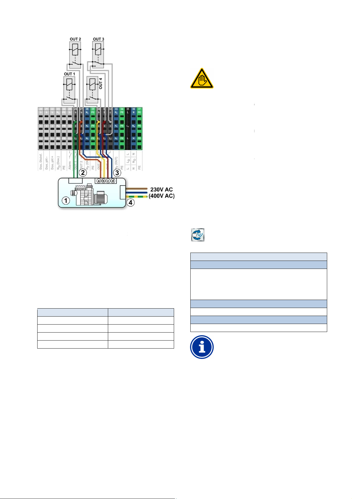
26
(optional)
Potential free control input for operating mode
Potential free control input for normal operation
Potential free control input for reduced output
potential free control input for increased output
External power supply for the filter pump
Allocation of inputs and outputs
for the connection schematic shown in the figure:
Relay switch output
Requisite user qualification:
SPECIALIST or
ELECTRICAL SPECIALIST
Connection, configuration, and start
control may only be performed by a TRAINED
SPECIALIST or an ELECTRICAL SPECIALIST as
defined in the chapter
offers the option of connecting and controlling a
Flockmatic control additionally offers the following
Reducing Flockmatic dosing output
Blocking flock dosing in the event of missing flow
three relay switch outputs for the filter
pump's various operating modes
Multiple flexibly programmable timers
Optional level monitoring via a switch input
Flockmatic pump
The configuration menu for Flockmatic control is called up with the
The following settings are available:
Inactive (Flockmatic control not used)
Off (Flockmatic used, but turned off)
Basic settings for Flockmatic control.
Allocation of a relay switch output
Flockmatic control can only be activated if you have
allocated a relay switch output to it beforehand.
rogrammable timer
This menu provides 3 freely programmable time intervals
Programming here is identical to programming the timers for the
Universal switch outputs,
Basic configuration
is used to configure the basic settings
for Flockmatic control. This is generally done once upon placing into
up of Flockmatic
Flockmatic pump
26 Flockmatic pump
26.1 Safety information
TRAINED
26.2 Overview
PoolManager®
Flockmatic pump.
PoolManager®
options:
•
•
• Flexible allocation of up to
•
•
-
User qualification.
1 Filter pump
2 Potential free control input on/off
3
3a
3b
3c
Joint contact for all
3d
potential free control inputs
4
(or 400V~)
The following
Function
Relay output 'Filter pump on/off'
Relay output 'normal operation'
Relay output 'reduced output'
Relay output increased output'
230V~
is required in the menu
OUT 1 [26]
OUT 2 [27]
OUT 3 [30]
OUT 4 [31]
26.3 Menu
following icon:
Menu Flockmatic pump
Flockmatic mode of operation
Selection of operating mode:
•
•
• On
• Timer
Programmable timer
Programming timers.
Basic configuration
26.3.1 P
for Flockmatic control.
Flockmatic pump
INFO
universal switch outputs, see
programmable timer.
26.3.2
The menu Basic configuration
operation.
User Manual PoolManager®
freely
61
Page 62
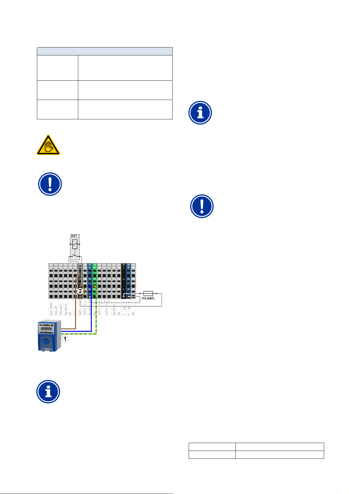
27
Electrical connection of filter pump control may only be
performed by an ELECTRICAL SPECIALIST as
rrents for the sum
of all relay switch outputs being used in 230V~ (in sum,
A Flockmatic pump's neutral conductor N and
terminal
and PE as shown in
control, you can
measuring cell can fundamentally be used for
temperature measurement. It represents a very simple
solution, as there is no need for additional installation
However, note that the temperature measured in the
from the actual pool
temperature. Changes in air temperature, sunshine, or
other influences, the water may heat up or cool down
Calibration cannot compensate for these effects, which
For this reason, the measurement precision to be
expected of the standard temperature sensor is
generally too marginal for reliable temperature
For controlling the heating system, you should
onal sensor directly
in the circulation circuit whose measurement. That
sensor's measurement signal needs to be independent
of external effects and representative for pool
Heating
The following settings are available:
Sub-menu Basic configuration
Flockmatic relay
output
Flockmatic dosing
rate
Level input
Flockmatic
26.4 Electrical connection
The relay switch output used for Flockmatic control.
(None / OUT 1 [26] / OUT 2 [27] / OUT 3 [30] /
OUT 4 [31] / pH+ [22] / pH- [21]).
None Flockmatic control is inactive
Desired Flockmatic dosing output in [%]:
• 100% Flockmatic pump runs non-stop
• <100% Cyclic turning on and off
Allocation of input for level monitoring of
flock canister (optional)
(IN 1 [6] / IN 2 [7] / IN 3 [8] / IN 4 [9] / none).
Requisite user qualification:
ELECTRICAL SPECIALIST
defined in the chapter User qualification.
IMPORTANT NOTICE!
Observe maximum flows
Observe the maximum permissible cu
max. 4A).
Please also refer to the Chapter 230V~ Power supply.
The following figure schematically shows the connection of a
Flockmatic pump to relay switch output OUT1.
27 Heating
27.1 Overview
PoolManager® offers the capacity to trigger a heating system.
The heating system is triggered via a simple relay switch output
(potential free or 230V~). The exact type and design of the heating
system is not important. There only needs to be a possibility to turn the
heating function on and off externally via a corresponding input.
INFO
Toggle switch OUT 4 [31/32]
If you need a toggle switch for heating
use the relay switch output OUT 4:
• [31b] Working contact
27.2 Temperature measurement
Heating control requires measurement of the water temperature.
PoolManager® three temperature inputs can be used to do so.
You'll find a detailed description in the chapter
Temperature measurement. It has all the sensor types supported by
PoolManager®.
• [32c] Resting contact
IMPORTANT NOTICE!
Measurement precision of the standard
temperature sensor in the measurement chamber
The standard temperature sensor in PoolManager
®
1 Flockmatic pump with power supply 230V~
2 Wire bridge in the terminal box from phase LF to centre
relay contact a
INFO
Connection of neutral conductor N and PE
protective earth PE can be connected to the
blocks intended for the purpose NF
the figure.
work.
measuring cell may deviate
along its path through the measurement water circuit.
fluctuate over time.
measurement and control.
therefore definitely install an additi
temperature.
27.3 Function
The desired temperature setpoint and a add-on switch hysteresis can
be configured as parameters.
The setpoint temperature should be configurable in a range between
10.0°C and 40.0°C.
Hysteresis ensures that heating control does not turn on and off for
marginal temperature changes, rather only when there is a certain
deviation from the setpoint.
Hysteresis is configurable in a range between 0.1°C and 5.0°C.
This temperature setpoint and the temperature hysteresis yield the
temperatures at which heating control turns on and off as follows:
Turn-on temperature Temperature setpoint minus half of hysteresis
Turn-off temperature Temperature setpoint plus half of hysteresis
User Manual PoolManager® 62
Page 63
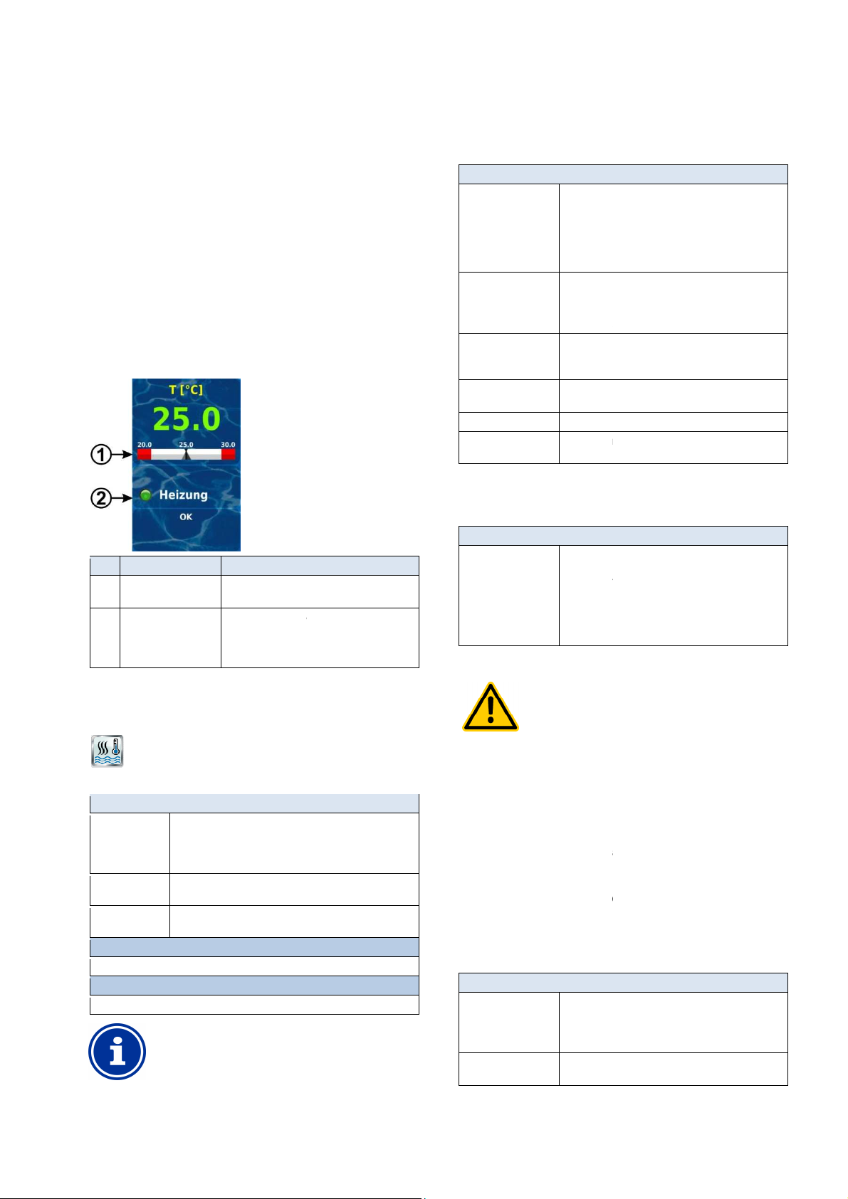
27
on temperature 24.9°C (value rounded)
off temperature 25.2°C (value rounded)
The hysteresis setting can be used to optimally adjust the control
The operating state of the heating system or solar heating system is
displayed in home view in the temperature module.
Display of temperature setpoint on the
measured value scale
heating
and/or solar heating.
When heating is running, the LED symbol
The configuration menu for heating control is called up with the
• Inactive (heating control not used)
Heating off (heating control used, but turned off)
Always heat (regardless of temperature!)
Automatic (automatic temperature control)
Desired pool temperature in [°C]
Permissible tolerance range for temperature control in
Allocation of a relay switch output
Heating control can only be activated if you have
allocated a relay switch output to it beforehand.
Basic configuration
is used to configure the basic settings
generally done once at the start
The following settings are available:
Temperature input used for measuring pool
temperature:
None (function inactive)
Temp. input 1 [3]
Temp. input 2 [4]
input 3 [5]
Relay switch output used for activating heating
(None / OUT 1 [26] / OUT 2 [27] / OUT 3 [30] /
OUT 4 [31] / pH+ [22] / pH
Heating control is inactive
Heating is not turned on when solar heating
is active (solar priority).
The output is turned off if the selected input is
in the state indicated.
freeze
Type and function
can be used to activate a frost protection
The temperature input used for measuring air
temperature
(optional for frost
None (function inactive)
Temp. input 1 [3]
Temp. input 2 [4]
Temp. input 3 [5]
Hazard via remote access
In some circumstances, hazards may be yielded via
remote access to the heating control system, e.g.
Potential consequence: Injury,
Release of remote access to heating control is
expressly PROHIBITED for all applications in which
the safety of persons, animals, and property is not
completely guaranteed at all times and under all
ances; especially for remote access.
Safety is exclusively in the system operator's
sphere of responsibility.
The device manufacturer disclaims all liability.
The following security settings are available:
Potential settings:
Local network
Local network & Web
Heating
Example 1
• Temperature setpoint 25.0°C
• Temperature hysteresis 1.0°C
Turn-on temperature 24.5°C
Turn-off temperature 25.5°C
Example 2
• Temperature setpoint 25.0°C
• Temperature hysteresis 0.3°C
Turn-
Turn-
system to the local circumstances.
27.4 Display in home view
Pos. Content Notes
1 Temperature setpoint
2 Status of heating
and/or solar heating
Status display of
illuminates.
27.5 Menu Heating
following icon:
27.5.1
The menu Basic configuration
for heating control. This is
Sub-menu Basic configuration
Pool Temperature
input
Relay output 'heating'
Blocked if solar
heating is active
Blocking by input. Yes
Anti-freeze See anti-
Temperature sensor
configuration
•
•
•
• Temp.
None
Yes / no
Yes
- [21]).
.
of temperature sensors.
-up.
27.5.1.1 Anti-Freeze
The menu anti-freeze
function for heating control.
Sub-menu Anti-freeze
Temperature input
Air
27.5.2 Safety settings
•
•
•
•
protection):
HAZARD!
Heating
The following settings are available:
Menu Heating
Operating mode
pool heating
Pool temperature
setpoint
Temperature
hysteresis
Basic configuration
Basic settings for heating control.
Safety settings
Safety settings for heating control.
•
•
•
[°C]
INFO
scalding.
material damage.
•
circumst
•
Sub-menu Safety settings
Allow remote access
Display in
Mode menu
•
• Inactive
•
•
Yes / no
User Manual PoolManager®
63
Page 64
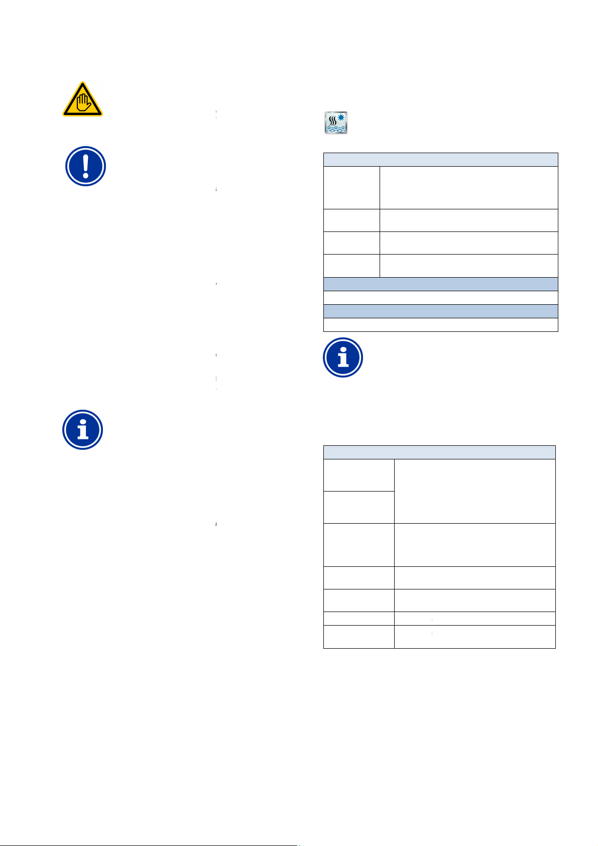
28
Electrical connection of heating system control may
only be performed by an ELECTRICAL SPECIALIST as
User qualification.
Observe the maximum permissible currents for each
switch output (max. 4A) and for the sum
of all relay switch outputs being used in 230V~ (in sum,
Please also refer to the Chapter
Depending on the type and model of the heating system, there are
establishing the electrical connection (potential
In general, the connection options already described for the universal
Universal switch output
offers the capacity to trigger a solar heating system.
The solar heating system is triggered via a simple relay switch output
(potential free or 230V~). The exact type and design of the solar
heating system is not important. There only needs to be the pos
to turn the solar heating function on and off externally.
switch for solar control, you can
use the relay switch output OUT 4:
Solar control requires measurement of the water temperature. For
temperature measurement.
Measurement of solar temperature is also required.
three temperature inputs can be used to
You'll find a detailed description in the chapter
It has all the sensor types supported by PoolManager
The function of solar control is based on conventional heating control.
As an additional parameter, the requisite temperature difference
between solar temperature and pool temperature can be entered. The
solar control system won't trigger until solar temperature is higher than
The operating state of the heating system or solar heating system is
displayed in home view in the temperature module.
display in home view.
menu for solar control is called up with the following
The following settings are available:
• Inactive (solar heating control not used)
Solar operation off (heating control used, but
stop solar operation (regardless of temperature!)
Automatic (automatic temperature control)
Desired pool temperature in [°C]
Permissible tolerance ra
Requisite temperature difference between solar
temperature and pool temperature.
Allocation of a relay switch
Solar control can only be activated if you have
allocated a relay switch output to it beforehand.
Basic configuration
is used to configure the basic settings
for solar control. This is generally done once at the start
The following settings are available:
The temperature inputs used for measuring pool
temperature and for solar temperature:
None (function inactive)
Temp. input 1 [3]
Temp. input 2 [4]
Temp. input
Relay switch output used for activating heating
(None / OUT 1 [26] / OUT 2 [27] / OUT 3 [30] /
OUT 4 [31] / pH+ [22] / pH
Solar control is inactive
Pool water may be
Solar temp. f must be lower than pool temp.
The output is turned off if the selected input is
in the state indicated.
freeze
function of temperature sensors.
Solar heating
27.6 Electrical connection
Requisite user qualification:
ELECTRICAL SPECIALIST
28.5 Menu Solar heating
The configuration
icon:
defined in the chapter
IMPORTANT NOTICE!
Observe maximum flows
individual relay
max. 4A)
various options for
free, 230V~,...).
switch outputs are available, see
connection options.
28 Solar heating
28.1 Overview
PoolManager®
INFO
Toggle switch OUT 4 [31/32]
If you need a toggle
• [31b] Working contact
28.2 Temperature measurement
more information, see Heating
PoolManager®
solar sensor.
measurement.
28.3 Function
For more information, see Heating function.
• [32c] Resting contact
230V~ Power supply.
sibility
Another one of the
connect a
Temperature
Solar heating
Menu Solar heating
Solar heating
mode of
operation
Pool temperature
setpoint
Temperature
hysteresis
Min. difference
solar → Pool
Basic configuration
Basic settings for solar control.
Safety settings
Safety settings for solar control.
•
• Non-
•
turned off)
nge for temperature control in [°C]
INFO
28.5.1
output
The menu Basic configuration
-up.
Sub-menu Basic configuration
Pool temperature
input
Solar temperature
input
Relay output 'heating'
®
.
Cooling function
Blocking by input. Yes
Anti-freeze See Anti-
Temperature sensor
configuration
•
•
•
•
None
Type and
3 [5]
- [21]).
cooled by way of the solar heater.
.
pool temperature in the value indicated.
28.4 Display in home view
For more information, see Heating
User Manual PoolManager®
64
Page 65
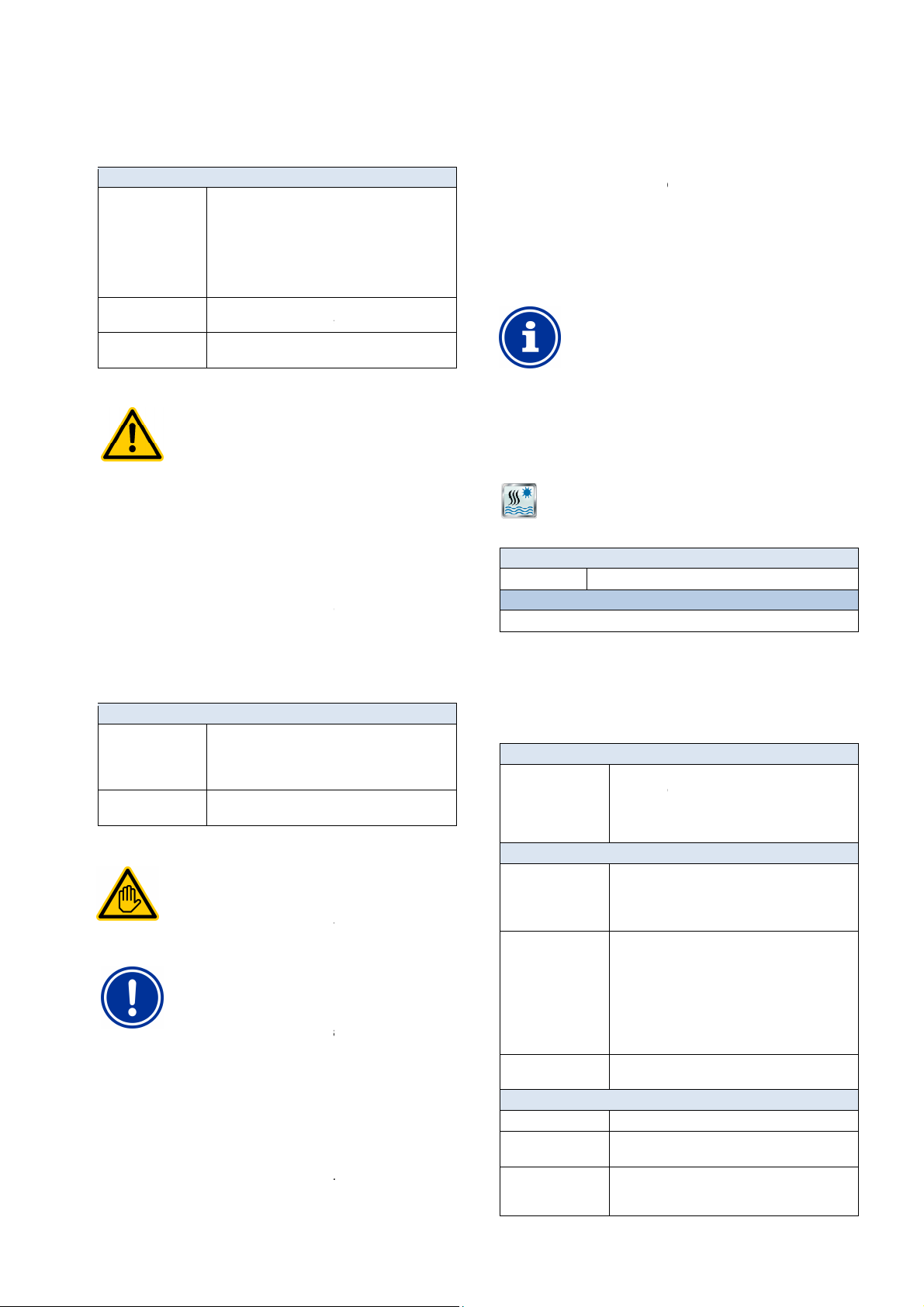
29
can be used to activate a frost protection
The temperature input used for measuring air
for frost protection):
Solar control (frost protection) does not trigger at air
temperatures below this threshold value
Type and function of temperature sensors.
In some circumstances, hazards may be yielded via
remote access to the solar control system, e.g.
Potential consequence: Injury,
Release of remote access to solar control is
expressly PROHIBITED for all applications in which
the safety of persons, animals, and property is not
completely guaranteed at all times and under all
circumstances; especially for remote acces
Safety is exclusively in the system operator's
The device manufacturer disclaims all liability.
Electrical connection of the solar control system may
only be performed by an ELECTRICAL SPECIALIST as
User qualification.
Observe the maximum permissible currents for each
switch output (max. 4A) and for the sum
of all relay switch outputs being used in 230V~ (in sum,
Please also refer to the Chapter
Depending on the type and model of the solar heating system, there
ablishing the electrical connection (potential
In general, the connection options already described for the universal
Universal switch output
e capacity to trigger an external salt
Cl, the current calculated dosing output for
disinfection (redox (mV)) is converted into a trigger signal for the salt
electrolysis system. Triggering can be optionally realised w
-
The control system adjusted the salt electrolysis system's production
eeded. The higher PoolManager
higher the salt electrolysis system's production is as well.
Suitable salt electrolysis systems
In order for this function to be used, the salt electrolysis
system used has to have the corresponding input for
external triggering, optionally for trigger pulses or for a
20mA current signal.
electrolysis
The configuration menu for triggering the salt electrolysis system is
The following settings are available:
Basic configuration
is used to configure the basic settings
for triggering salt electrolysis. This is generally done once at the start
available:
• Inactive (salt electrolysis not used)
Trigger pulses
(a pulse triggers a production cycle in the salt
electrolysis system)
Power output 0/4
pulse
The relay switch output used for pulse control:
(None / OUT 1 [26] / OUT 2 [27] / OUT 3 [30] /
OUT 4 [31] / pH+ [22] / pH
Control
Duration of one salt electrolysis
cycle. After that period has passed, PoolManager
generates a
For lower dosing outputs, the time between two
pulses extends accordingly.
In order to reduce production in general,
value can be entered for the operating cycle.
control
Power output 0/4
Power output for
Minimum current emitted at 0% dosing output.
Maximum current emitted at 100% dosing output.
Salt electrolysis
28.5.1.1 Anti-freeze
The menu anti-freeze
function for solar control.
Sub-menu Anti-freeze
Ambient temperature
input
Anti-freeze
temperature
Temperature sensor
configuration
28.5.2 Safety settings
temperature
(optional
• None (function inactive)
• Temp. input 1 [3]
• Temp. input 2 [4]
• Temp. input 3 [5]
HAZARD!
Hazard via remote access
scalding.
material damage.
•
•
sphere of responsibility.
The following security settings are available:
Sub-menu Safety settings
Allow solar remote
access
Display in
Mode menu
28.6 Electrical connection
•
Potential settings:
• Inactive
• Local network
• Local network & Web
Yes / no
Requisite user qualification:
ELECTRICAL SPECIALIST
defined in the chapter
IMPORTANT NOTICE!
Observe maximum flows
individual relay
max. 4A)
are various options for est
free, 230V~,...).
switch outputs are available, see
connection options.
s.
230V~ Power supply.
29 Salt electrolysis
PoolManager® offers th
electrolysis system.
For PoolManager®
ith control
pulses or via a current output 0/4
as n
INFO
0/4-
29.1 Menu Salt
called up with the following icon:
Salt electrolysis
Menu Salt electrolysis
Salt electrolysis Active / inactive
Basic configuration
Basic settings for salt electrolysis.
29.1.1
The menu Basic configuration
up.
The following settings are
Sub-menu Basic configuration
Operating mode Salt
electrolysis
For the operating mode Control
Relay output
Salt electrolysis
working cycle
Pulse length of the
trigger pulse
Only for operating mode
Power output used
Min. power
(at 0% dosing output)
Max. power
(at 100% dosing
output)
•
•
None
is 100%.
control
Duration of
20mA.
®
current dosing output is, the
-20mA
only
- [21]).
ing is inactive
control pulse if the current dosing output
pulse in [ms].
-20mA
controling salt electrolysis.
system production
a larger
®
-
User Manual PoolManager®
65
Page 66
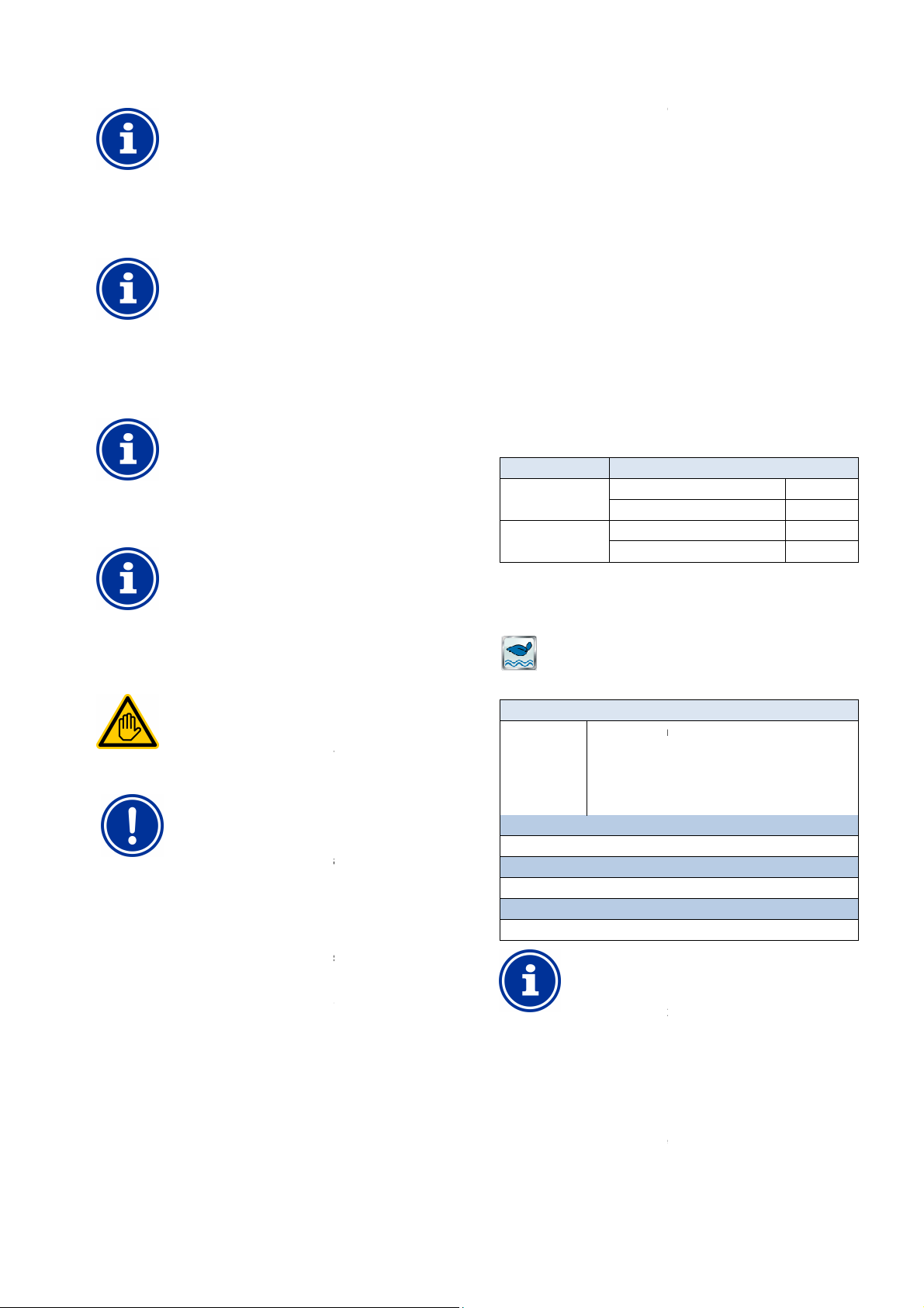
30
Allocation of relay switch output
Salt electrolysis control can only be activated if
have allocated a relay switch output or a power output
to it beforehand, depending on operating mode.
impulses, the interval between two
sequential pulses varies depending on the
dosing output. At 100% dosing output, the interval will
correspond to the operating cycle entered. For lower
dosing outputs, the interval is expanded accordingly;
e.g. for 50% dosing output, the interval is doubled.
Current dependency
ing via a power output 0/4
current emitted is interpolated between the minimum
and maximum values indicated based on the current
SA4 needed
the salt electrolysis sys
20mA, the following optional plug
20MA (Art. no. 127011)
Electrical connection of the solar control system may
only be performed by an ELECTRICAL SPECIALIST as
User qualification.
Observe the maximum permissible currents for each
switch output (max. 4A) and for the sum
of all relay switch outputs being used in 230V~ (in sum,
Please also refer to the Chapter
, a relay switch output is
witch and is linked with the salt
electrolysis system's corresponding control input. Please use the
corresponding connection diagram in the section
Connecting a device with the
20mA
SA4 is connected with the corresponding
salt electrolysis system power input. For more details, please refer to
the separate documentation for the power outputs
Eco mode (energy saving mode)
The function eco mode (energy saving mode) facilitates automatic,
timed toggling of the pool from normal mode into an energy
operating mode. The two operating modes are designated as follows:
you
current
20mA, the
tem via a power
in module
saving operation)
Actual execution of the two operating modes can be realised in a very
Example (for polls with over overflow gutter):
Circulation via the overflow gutter
Circulation via the floor drain
Toggling the water circuits for both operating modes can be
realised with, for example, stem valves.
The function eco mode provides the following options:
Multiple flexibly programmable timers
exible allocation of relay switch outputs for the two operating
Operation of relay switch outputs optionally as potential free
Link with an external switch or
for this function are connected as follows for the
Status of the allocated relay switch outputs
Relay output 'normal mode'
Rely output 'eco mode'
output 'normal mode'
Rely output 'eco mode'
Eco mode
The following settings are available:
• Inactive (Eco mode not used)
(Automatically timed toggling between operating
Allocation of a relay switch output
Eco mode can only be activated if you have allocated a
relay switch output to it beforehand.
rogrammable timer
This menu provides 6 programmable time intervals
Eco mode is activated during the programmed
activated outside of the programmed times.
Programming here is identical to programming the timers for the
universal switch outputs, see
Eco mode (energy saving mode)
INFO
or power output
INFO
Pulse interval dependency
on dosing output
When using control
INFO
on dosing output
When control
dosing output.
INFO
Plug-in module PM5-
To control
output 0/4is needed:
PM5-SA4 CONVERTER 0/4-
29.2 Electrical connection
Requisite user qualification:
ELECTRICAL SPECIALIST
defined in the chapter
IMPORTANT NOTICE!
Observe maximum flows
individual relay
max. 4A)
For the operating mode Control pulses
operated as a potential free s
outputs Connection options
potential free control input.
For the operating mode Power output 0/4-
optional plug-in module PM5-
30
• Normal mode (normal pool operation)
-
-
230V~ Power supply.
Universal switch
, a power outlet on the
0/4-20mA.
-saving
• Eco mode (energy-
flexible manner.
• Normal mode
• Eco mode
(reduction of thermal loss)
•
•
• Fl
modes
•
switch or as 230V~-output
•
push button for toggling the
operating mode
The two relay outputs
respective operating mode:
Operating mode
(Normal operation)
Eco mode
(Energy saving mode)
Relay
On
Off
Off
On
30.1 Menu Eco mode
The configuration menu for
icon:
Eco mode
Menu Eco mode
Operating mode
Programmable timer
Programming timers.
Basic configuration
Basic settings for solar control.
Safety settings
Safety settings for solar control.
• Normal mode
• Eco mode
• Time switch
modes)
INFO
30.1.1 P
Programmable timer.
is called up with the following
for eco mode.
times; normal mode is
Universal switch outputs,
User Manual PoolManager®
66
Page 67
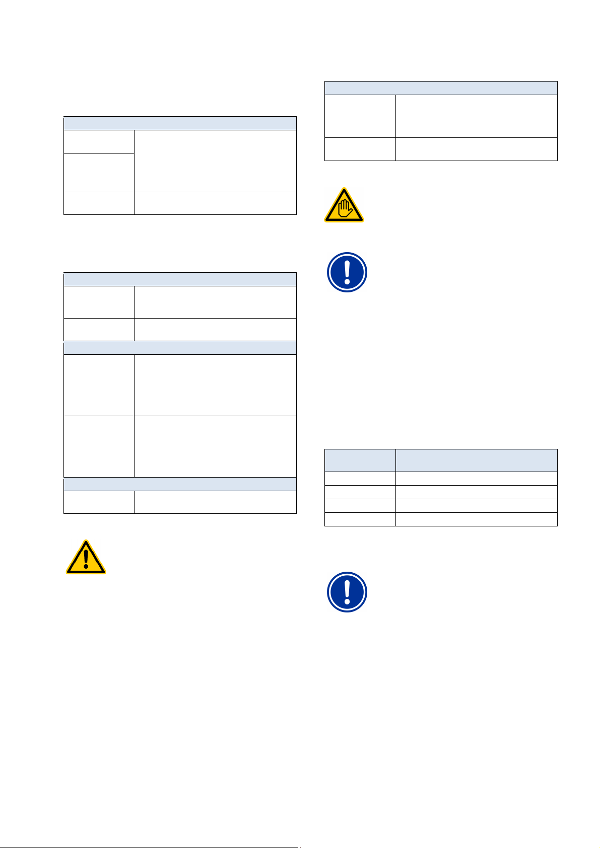
31
hazards can be yielded
from remote access to the eco mode function
Release of remote access to the eco mode function
s in
which the safety of persons, animals, and property
is not completely guaranteed at all times and under
Safety is exclusively in the system operator's
The electrical connection for eco mode may only be
performed by an ELECTRICAL SPECIALIST as
currents for each
individual relay switch output (max. 4A) and for the sum
of all relay switch outputs being used in 230V~ (in sum,
The externally connected switch or switch contact
absolutely must be potential free (voltage free).
Otherwise, residual currents may arise, which can,
Universal switch inputs IN 1 ... IN 4
30.1.2 Basic configuration
The menu Basic configuration is used to configure the basic settings
for eco mode. This is generally done once at the start-up.
The following settings are available:
Sub-menu Basic configuration
Relay output 'normal
mode'
Rely output
'Eco mode'
External switch or
push buttons
30.1.2.1 External switch or push buttons
The eco mode function can be linked with an external switch or device,
which facilitates turning the function on or off manually.
The following settings can be configured:
Sub-menu External switch or push button
External switch Selection of an input to which the external switch is
Type of external
switch
For on/off switch only
External switch on Defines the operating mode when external
External switch off Defines the operating mode when external
For devices only
Function of external
device
30.1.3 Safety settings
Relay switch outputs used for both operating modes
Normal mode and Eco mode
(None / OUT 1 [26] / OUT 2 [27] / OUT 3 [30] /
OUT 4 [31] / pH+ [22] / pH- [21]).
In order to activate the Eco operation, it is sufficient
to allocate at least one of the two relay outputs.
See External switch or push button.
connected
(IN 1 [6] / IN 2 [7] / IN 3 [8] / IN 4 [9] / none)
On/off switch or device.
switch is turned on:
• Eco mode
• Normal operation
• AUTO,
(Operating mode controlled by PoolManager®)
switch is turned off:
• Eco mode
• Normal operation
• AUTO,
(Operating mode controlled by PoolManager®)
Toggle eco mode / normal mode /
eco mode / ... (fixed setting)
HAZARD!
Hazard via remote access
Under certain circumstances,
depending on the concrete form of realisation.
Potential consequence: Injury,
material damage.
•
is expressly PROHIBITED for all application
The following security settings are available:
Sub-menu Security settings
Allow remote access Potential settings:
Display in
Mode menu
30.2 Electrical connection
• Inactive
• Local network
• Local network & Web
Yes / no
Requisite user qualification:
ELECTRICAL SPECIALIST
defined in the chapter User qualification.
IMPORTANT NOTICE!
Observe maximum flows
Observe the maximum permissible
max. 4A)
Please also refer to the Chapter 230V~ Power supply.
Depending on how eco mode is realised, there are various options for
establishing the electrical connection (potential free, 230V~,...).
In general, the connection options already described for the universal
switch outputs are available, see Universal switch output
connection options.
31 Universal switch inputs IN 1 ... IN 4
PoolManager® provides four universal switch inputs that can be
connected to external potential free switches or switch contacts:
Universal switch
input
IN 1 [6] Switch input IN 1 [terminal block 6]
IN 2 [7] Switch input IN 2 [terminal block 7]
IN 3 [8] Switch input IN 3 [terminal block 8]
IN 4 [9] Switch input IN 4 [terminal block 9]
Several of the potential applications are described in connection with
the various add-on functions, e.g. connection of an external switch of
push button.
Description
IMPORTANT NOTICE!
potential free
among other things, destroy electronic components.
all circumstances; especially for remote access.
•
sphere of responsibility.
• The device manufacturer disclaims all liability.
User Manual PoolManager® 67
Page 68
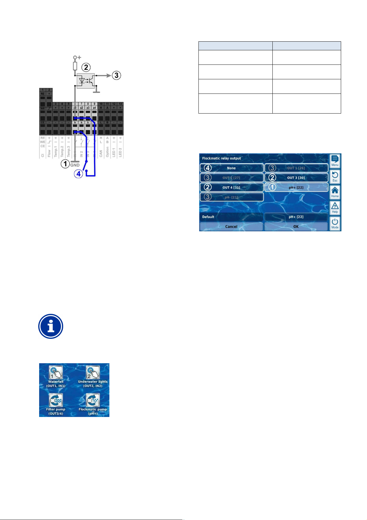
32
Hardware resources (inputs and outputs)
The following figure shows the internal wiring of the input IN 1. The
other inputs IN 2 ... IN 4 are set up identically.
Internal ground connection of terminal b
1
(The b terminals on all four switch inputs are internally linked to
ground)
2 Optical coupler for galvanic isolation (internal)
3 Signal for continued internal processing
4 Externally connected potential free switch
32 Hardware resources (inputs and outputs)
The use of numerous functions is limited by the hardware resources
available. This includes the following inputs and outputs:
• Relay switch outputs OUT 1 ... OUT 4
• Universal switch inputs IN 1 ... IN 4
• Temperature inputs Temp.1 ... Temp.3
• Power outputs (optional plug-module PM5-SA4)
Add-on functions can only be activated if the requisite hardware
resources are still available.
INFO
Add-on box (feature box)
An external add-on box (feature box) with add-on
The menu Add-on functions shows the resources that are already
being utilised:
inputs and outputs is in development.
Add-on function utilised resources
Universal switch output 1
"Water fall"
Universal switch output 2
"Underwater lights"
Filter pump Relay switch output OUT 3
Flockmatic pump Relay switch output pH+
Relay switch output OUT 1
Switch input IN 1
Relay switch output OUT 2
Switch input IN 2
Relay switch output OUT 4
(This output can only be used if no
pH plus dosage is being used)
When inputs and outputs are allocated to a certain function, the
resources already being utilised are deactivated.
They are shown in grey lettering and cannot be selected. The previous
function may have to be deactivated first. The following figure shows
an example:
1 Current selection (white background)
Additional selection options
2
(free resources, white lettering)
Deactivated selection options
3
(resources already being utilised, grey lettering)
Selection "none"
4
The corresponding function is no longer linked with a resource and
therefore cannot be activated.
The corresponding resources are available for other
functions.
In the example shown, the following resources are utilised:
User Manual PoolManager® 68
Page 69
33
All activities described in Part C may only be performed
by TRAINED SPECIALISTS as defined in the Chapter
HAZARD!
HAZARD!
Safety information for performing installation, start-up, and maintenance work
Part C:
Installation, start-up, maintenance
Requisite user qualification:
TRAINED SPECIALIST
User Qualification.
33 Safety information for performing installation,
start-up, and maintenance work
Hazard from electrical current
PoolManager® begins to run as soon as there is
voltage on the incoming power line. It is possible that
dosage pumps start or that add-on functions are
turned on or toggled. Contact with current-carrying
components can lead to an electrical shock.
Potential consequence: Grave health hazard and
death, material damage
• Installation and maintenance work on the unit
must always be performed in a potential free
state.
• The unit must be secured against turning on
while performing work!
• Add-on component groups have to be
mounted/dismounted in a potential free state.
• Cables also have to be connected in a
potential-free state.
• There should always be safety equipment
present that is independent of the controller.
• Password protection must be activated as
needed.
• The country's local safety requirements must
be met.
• Immediately after completing work, all safety
and security equipment must be reinstalled and
rendered functional.
• Non-compliance with safety information can
lead to the unit becoming defective, to mortal
danger, and to warranty forfeit.
34 Wall mounting
The unit is not suitable for installation in areas
exposed to explosion hazards.
34.1 Selecting the installation location
• Level, flat surface.
• The free space surrounding the unit must be large enough for
trouble-free operation and maintenance. Covers must remain
removable. Be sure that the electrodes are freely accessible in
order to guarantee trouble-free handling.
• The control unit's casing opens to the left.
• The control unit's display should be approximately at eye level.
• At least 20-cm of clearance is needed underneath the unit for
installing hoses.
• No parts sensitive to moisture underneath the unit
• A damp room DC SCHUKO socket no more than 1.5 m away.
• All hoses and cables must be installed free from kinks and
abrasion.
• No hose line should be longer than 5 m.
• Hoses may not be run directly over pipes or systems that
transmit heat.
• Direct sunlight, thermal radiation, frost, and moisture must be
avoided.
• Ensure sufficient ventilation.
• No current-carrying lines, relays, electric motors, etc. in the near
vicinity.
• The installation location should be as close to measurement
water extraction and return as possible.
34.2 Installation
• The base plate can be used as a drill template by holding it on the
intended location and marking the drill holes on the wall.
• After the base plate is safely anchored to the wall, including
mounted controller and measuring sensory, the covers can be
inserted into the tongue and groove connection supplied.
35 Electrical connection
PoolManager® is designed and built according to the applicable
guidelines. Prior to leaving the factory, it was carefully inspected and
departed from the factory in a state free of technical issues.
Hazard-free operation is only possible when all information included in
this manual is observed.
The supply current for the unit may not exceed 240V/50 Hz. The
permissible operating temperature is 0 to 50°C, permissible air
humidity is 0-90%.
As is standard with all electrical connections, be sure that all plug
connections are secured against water.
35.1 Measurement grounding
There must be a ground for both measurement water extraction and
return. The ground connections have to be connected with a safe
ground in order to facilitate the conduction of potential in pool water.
IMPORTANT NOTICE
The ground MUST be installed. Ensure that this
ground functions without issues.
Please always make sure that there is no residual
current to the swimming pool's water. In cases of
doubt, we recommend having measurement taken
professionally.
35.2 Blocking the circulation pump
PoolManager® is equipped with a double pump lock, which offers the
highest level of security. That is why it has 2 separate power
connections, with one power connection directly to the controller and
the other connection supplying the dosage pump.
On the one hand, the flow switch in the measuring cell ensures that
the dosage pump is only turned on when there is sufficient water in the
measuring cell.
On the other hand, the dosage pumps are supplied with a separate
current from the power supply. That power feed absolutely must be
connected such that the dosage pumps are only supplied with power
when the circulation pump is running.
This guarantees that the dosage pump only runs when the pool water
is being run through the circulation system.
User Manual PoolManager® 69
Page 70
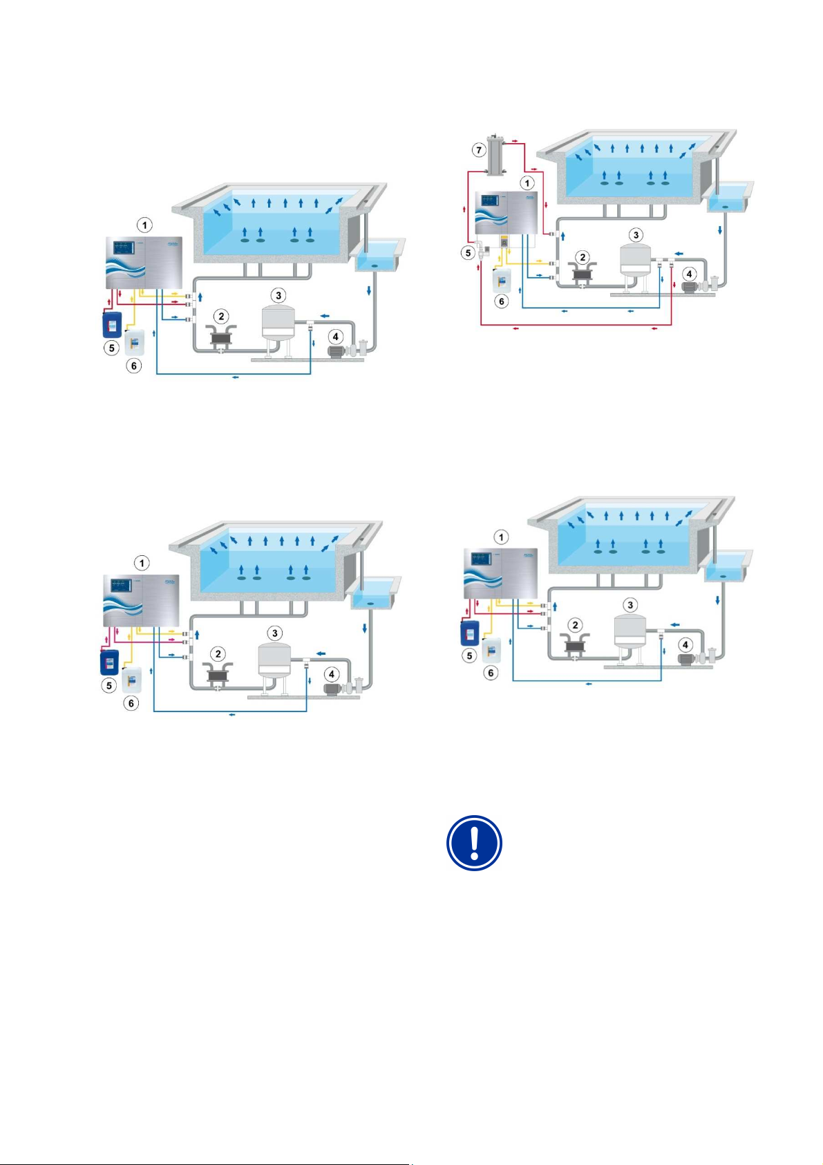
36
Installation into the circulation system
36 Installation into the circulation system
Depending on the maintenance method chosen, install PoolManager®
on the circulation system as follows.
36.1 PoolManager® Chlorine installation diagram
1. PoolManager® Chlorine
2. Heat exchanger/Heating
3. Sand filter
4. Circulation pump
5. ChloriLiquid
6. pH minus / pH plus
36.2 PoolManager® Oxygen installation diagram
36.3 PoolManager® Bromine installation diagram
1. PoolManager® Bromine
2. Heat exchanger/Heating
3. Sand filter
4. Circulation pump
5. Magnet valve
6. pH minus / pH plus
7. Brominator
36.4 PoolManager® PRO installation diagram
1. PoolManager® Oxygen
2. Heat exchanger/Heating
3. Sand filter
4. Circulation pump
5. BayroSoft
6. pH minus / pH plus
1. PoolManager® PRO
2. Heat exchanger/Heating
3. Sand filter
4. Circulation pump
5. ChloriLiquid
6. pH minus / pH plus
36.5 PoolManager® installation
IMPORTANT NOTICE
Ensure that connections are sealed tightly for all hose
and assembly connections.
No liability for any leakage!
36.5.1 Connection with the circulation system
• Install the tapping saddles for measurement water extraction and
return and injection valves as shown in the diagrams.
• Use the Teflon tape provided to install measurement water
extraction and return, as well as injection valves.
User Manual PoolManager® 70
Page 71
37
for water extraction
and return for the brominator according to the
Connect the brominator with the magnet valve
Configure water flow through the measuring cell such
sufficiently and evenly rotate on
the gold plate. Avoid too much flow, which can be
The lifespan of the gold electrodes in the chlorine
measuring cell is ca. 5 years. Depending on the
degree of utilisation, it may be necessary to replace a
Maintenance
PoolManager® Bromine only
• Install the tapping saddles
diagram
•
and circulation system as shown in the diagram.
• Connect the measurement water extraction with PoolManager®
pre-filter using a piece of measurement water hose that is
sufficiently long.
• Connect the measuring cell's outlet with measurement water
return using a piece of measurement water hose that is sufficiently
long. Measurement water can also be fed back to the surge water
container, if present.
• Connect the pressure line (hose) provided for pH with the
pressure side (right connection) of the right hose pump. Connect
the other end with the injector on the circulation line.
PoolManager® Chlorine and Oxygen only
Connect the pressure line provided for ChloriLiquid or
BayroSoft with the pressure side (right connection) of
the hose pump for disinfection. Connect the other end
with the injector on the circulation line.
• Connect the suction lance's hose for pH with the suction side (left
connection) of the dosage pump for pH.
• Plug the suction lance's plug into the respective socket on the unit
(see imprint on the unit).
PoolManager® Chlorine and Oxygen only
• Connect the suction lance's hose for ChloriLiquid
or BayroSoft with the suction side (left connection)
of the dosage pump for disinfection.
• Plug the suction lance's plug into the respective
socket on the unit (see imprint on the unit).
• Open the package with the liquid water maintenance products and
insert the suction lances vertically down to the floor.
IMPORTANT NOTICE
Place the packaging for liquid water maintenance
products (pH-/pH+, ChloriLiquid, BayroSoft) into
appropriate containers.
36.5.2 Configuration water flow
Use the black adjustment screw to the left of the measuring cell only
for making fine adjustments to flow rate. Larger changes can be made
using the tap on the measurement water extraction.
PoolManager® Chlorine, Bromine, and Oxygen only
Configure water flow through the cell such that there is
ca. 1-2 mm of clearance between the float and the top
edge of the proximity switch.
PoolManager® PRO only
that the cleaning balls
recognised when the cleaning balls hop.
Bubble formation in the measuring cell:
Should you find bubbles are forming in the measuring cell, then
inspect the measurement water circuit for leakage.
If the measurement water circuit is sealed tightly yet there are still
bubbles forming, then please open up the black adjustment screw on
the left side of the measuring cell further and choke measurement
water using the tap on the measurement water extraction. Small
adjustments are made using the black adjustment screw.
37 Maintenance
IMPORTANT NOTICE
Use only replacement parts and sensors from the
manufacturer. Otherwise, the warranty will be
forfeited.
Some PoolManager® parts are subject to abrasion due to chemical
and mechanical strain. Therefore, regular control is necessary for safe,
long-term operation. Regular precautionary maintenance of the system
protects against unplanned operating interruptions.
37.1 Monthly maintenance
• Visual inspection of all dosage lines and hoses
• Check filter screen, clean as needed
• Check water values using the test kit provided, adjust electrode
settings and calibration as necessary
37.2 Quarterly maintenance
• Visual inspection of all dosage lines and hoses
• Check screen, clean as needed
• Check water values using the test kit provided, adjust settings and
calibration as necessary
• Calibration of pH and redox electrodes using the buffer solutions
provided
• Calibration of chlorine electrodes (PoolManager® PRO only)
• Maintenance of injection points
37.3 Annual maintenance
• Visual inspection of all dosage lines and hoses
• Check screen, clean as needed
• Check water values using the test kit provided, adjust settings and
calibration as necessary
• Replace pH and redox electrodes and calibrate using fresh buffer
solutions
• Replace the chlorine measuring cell's glass electrode and
calibrate the chlorine measurement cell (PoolManager® PRO only)
• Maintenance of injection points
• Replace the hoses on the dosage pumps
PoolManager® PRO only
gold electrode earlier.
User Manual PoolManager® 71
Page 72
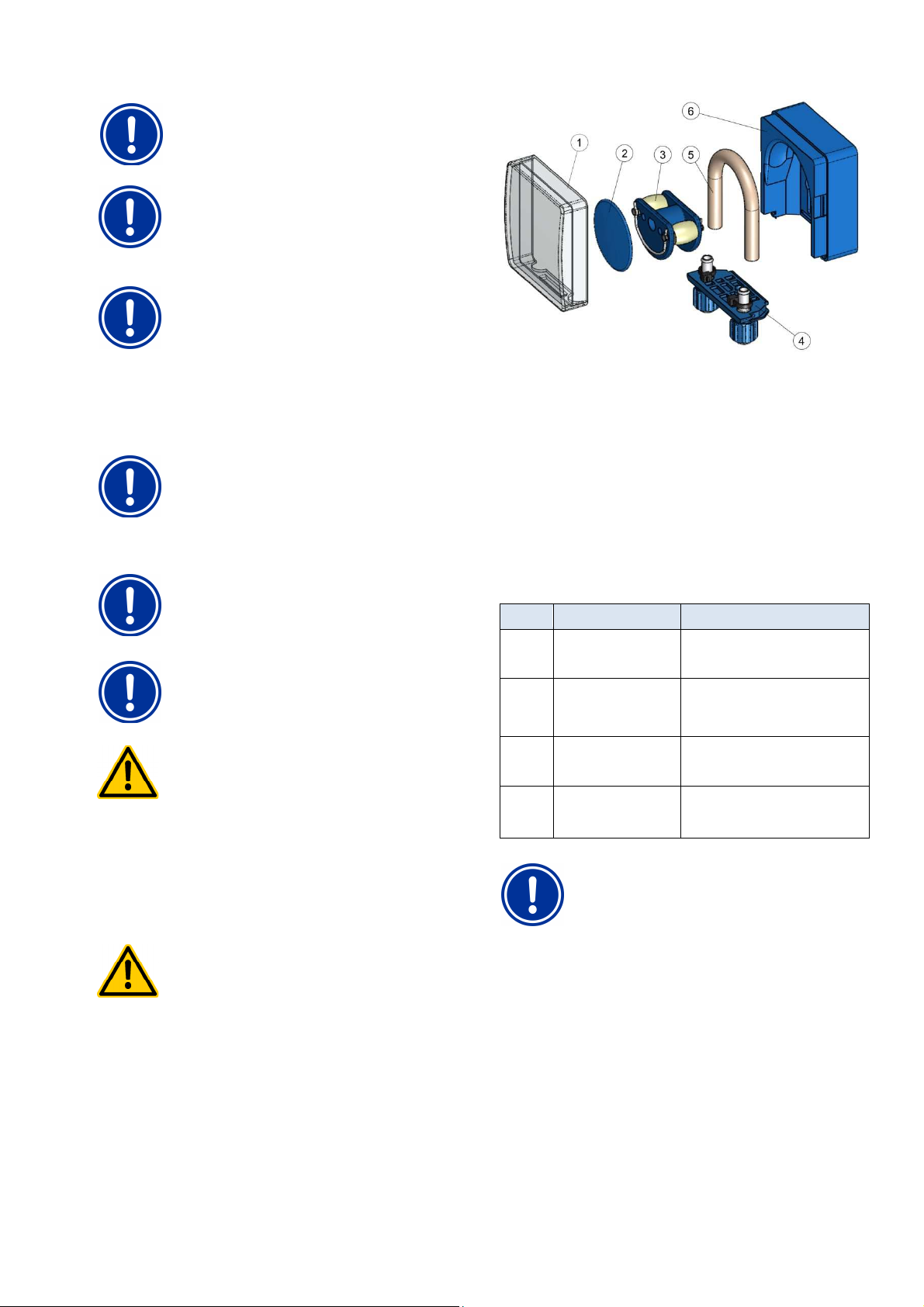
38
HAZARD!
HAZARD!
Winter breaks
NOTE
Do not use buffer solutions that are more than 12
months old.
NOTE
The lifespan on gas electrodes depends on the
operating conditions and the water's properties. It is
normally ca. 12 months; storage time is applied at
50%.
NOTE
Maintenance frequency is only partially dependent
upon utilisation intensity. Chemical strain, for example,
on plastic parts begins immediately upon first contact
with the medium and is not dependent upon the type of
utilisation.
37.4 Cleaning
Clean the unit's surface as needed using a towel that is soft and free
of fuzz. Only use a small amount of water, if necessary.
IMPORTANT NOTICE
Do not use aggressive cleaning products.
37.5 Dosage pump hose replacement
NOTE
Never grease hoses!
NOTE
Only original replacement pump hoses may be used!
Hazard due to chemicals
Corrosive product residue may come out of the pump
hose when pulled off.
Potential consequence: Grave health hazard
(chemical burns) and material damage
• Always be sure to empty pump hoses and feed
lines first.
• When necessary, use protective eye wear and
gloves and protect the surrounding area from
escaping product residue using a towel .
Hazard due to rotating parts
The dosage pump's rotor may start immediately.
Potential consequence: Crushing of fingers!
Ensure that the dosage pump remains separated
from the operating voltage (unplug) when replacing a
hose!
The dosage pump's hose is replaced without removing the rotor.
• Remove the empty suction and pressure hoses from the hose
fastener. To do so, loosen the blue clamp screws.
• Remove transparent cover 1 from the pump.
• Remove transparent cover 2 from the rotor.
• Turn rotor 3 such that the flat side faces left and is vertical.
• Pull hose fastener 4 from its bracket and lift on the left side.
• Turn rotor 3 clockwise and remove the cable while lifting on it
until it is completely free.
• To install, perform in the opposite order.
Either the hose can be replaced alone, or the hose and hose fastener
can be replaced jointly.
It is recommended to replace hose and hose fastener jointly.
Art. no. Designation Application
127302 Replacement hose set
1.5 l/h (hose with hose
fastener)
127352 Replacement hose set
3.0 l/h (hose with hose
fastener)
127303 Replacement hose set
1.5 l/h (hose with hose
fastener)
127353 Pump hose 3.0 l/h (hose
without hose fastener)
Chlorine and pH for pool sizes up to ca.
100 m3
Chlorine and pH for pool sizes of
ca.100 m3 to ca. 200 m3 and for dosing
BayroSoft.
Chlorine and pH for pool sizes up to ca.
100 m3
Chlorine and pH for pool sizes of
ca.100 m3 to ca. 200 m3 and for dosing
BayroSoft.
NOTE
If only the hose is being replaced, then the following
absolutely must be observed during installation
• The hose sits securely in the grommets.
• Under no circumstances may the hose be twisted
when installed.
• Ensure the hose clip sits securely.
38 Winter breaks
No special measures are necessary for short breaks in usage (e.g.
several days).
For longer operational breaks of multiple weeks, such as the winter
months, the following work must be performed:
• Remove suction lances from the canisters and rinse them with
water.
• Close packages, store them in a cool and dry location protected
from UV radiation.
• Rinse hose pumps with water. To do so, run the pumps in
manual mode.
User Manual PoolManager® 72
Page 73
39
Remove the dosing hoses from the pumps.
Empty the measurement water circuit and hose pumps
Remove glass electrodes (pH and Rx electrode) from the
easuring chamber and seal screw apertures.
Store electrodes moistly. To do so, fill the quiver with water and
After winter has passed, follow the instructions for first start
In doing so, be sure to inspect all components for their capacity to
All dismounted parts (electrodes, dosage hoses) must be remounted
. In doing so, fo
up and calibrate the electrodes as described.
If disposing of the device after its service life, be sure to rinse it
thoroughly and drain all water. This device has been manufactured in
e ROHS directive and the German laws on
electronic equipment disposal. Do not dispose of this equipment along
Deliver the device to a suitable and accredited collection point.
Commissioning step by step
has a menu for the first start
parameters relevant to successful installation.
up can be called up at any time as follows:
Service functions
cuted:
Entry
Here, select the default set that best fits. In
cases of doubt, please check all default
values for their validity for the respective
installation.
For safety reasons, activation of the defaults
has to be confirmed at this point.
Pool volume of the connected swimming
pool.
Hose configuration of the pump hoses used.
This display is used to check the settings
made at the factory according to device
configuration.
Oxygen:
point calibration pH. Please proceed as
described in the section
When refilling the pool, it may be sensible to
expand the top and bottom pH value alarms
and to adjust the p
can fluctuate somewhat during the starting
phase.
CAUTION: If the parameters are changed,
make absolutely sure that the val
back as soon as the pool water has stablised.
You can also use the configuration assistant.
Step 6: Manual dos. O2 (BayroSoft)
The dosing volume (for 0.5l BayroSoft/10m
water volume) is calculated upon entering the
pool volume and can be started here.
In order to increase the dosage volume for
the first dosage, thereby increasing the
certainty of disinfection, it's also possible to
select 2x or 3x the dosage volume.
Dosage volume is calculated by entering the
pool volume and is displayed here to check
(0.5l BayroSoft/10m
changed manually.
Select the dosage day such that it is directly
before the largest water
(e.g. high amount of swimming).
Temperature compensation ensures that
more BayroSoft is dosed for higher water
temperatures (higher product consumption). It
should be
Decommissioning
• Remove the unit from the power supply.
•
• Turn off measurement water supply.
•
completely.
•
m
•
screw in the electrode
• Store electrodes in a location from frost.
render the system operational again.
function.
at their intended locations.
Check the settings in PoolManager
®
for first start-
-up to
llow the procedure
40
PoolManager®
This menu for first start-
The following steps are exe
Action
Step 1: Menu language
Configuration of menu language
Step 2: Set default values
Here, the desired default set
can be selected and
activated.
-up. This menu covers all
commissioning step by step
39 Decommissioning
compliance with th
with regular waste.
Step 3: System parameters
Configuration of pool and
system parameters
Variation A: PoolManager®
Step 4: Calibration
Calibration (comparison) of
measured pH value
Step 5: Control parameters pH
Configuration of the most
important parameters for
pH control
Start manual dosing
1-
Calibration pH.
-range, as the pH value
ues are set
3
Step 7: Dosage parameters O2
Configuration of the most
important parameters for
automatic BayroSoft dosing.
User Manual PoolManager®
3
water volume). It can be
usage expected
set at least to normal.
73
Page 74
40
Commissioning step by step
Variation B: PoolManager® Chlorine/Bromine
Step 4: Calibration
Calibration (comparison) of
measured value for pH and
redox
Step 5: Control parameters pH
Configuration of the most
important parameters for
pH control
Step 6: pH Value configuration
Possibility for automatically /
manually setting the pH value
in the pool water
Step 7: Manual dosing mV (Cl / Br)
Configure the desired
chlorine or bromine level and
calculate the associated
redox (mV) value
Step 8: Control parameters mV (redox)
Configuration of the most
important parameters for
redox control
1-point calibration pH. Please proceed as
described in the section Calibration pH.
1-point calibration mV (optional). Please
proceed as described in the section
Calibration redox (mV).
When refilling the pool, it may be sensible to
expand the top and bottom pH value alarms
and to adjust the p-range, as the pH value
can fluctuate somewhat during the starting
phase.
CAUTION: If the parameters are changed,
make absolutely sure that the values are set
back as soon as the pool water has stablised.
You can also use the configuration assistant.
Display shows the configured pH setpoint and
the current pH value in the pool water.
NOTE The pool water's pH value first has to
be set to pH 7.2 in order to facilitate
configuration of the redox value without issue.
Set pH operation mode to auto if
PoolManager® should make the configuration
fully automated. This process will take some
time, depending on pool size and water
quality.
Set operating mode to manual if you would
like to configure the pH value via manual
addition of pH-elevator and -reducer.
The matching setpoint will depend on the
pool. It has to be calculated for the water in
the respective pool. Proceed as follows:
Set the pH value to pH 7.2
(see previous step)
Set the desired chlorine level in the pool via
manual dosing (or via manual addition of
chlorine) (in Germany, the recommended
value of 0.5 - 0.6 mg/l can also be set higher).
The volume of ChloriLiquid dosed is
determined by PoolManager® via the pool
volume entered. This volume can be
overwritten manually.
Check the desired chlorine level via manual
measurement (DPD). The redox value in
[mV], which PoolManager® shows for the
desired chlorine volume, is also the value that
has to be entered as the setpoint in the next
step.
Set the mV value as the setpoint you read in
the previous step for the desired chlorine
level. Adjust the bottom and top alarm
accordingly. Check the proportional range.
You can also use the configuration assistant.
Action Entry
Variation C: PoolManager® PRO
Step 4: Calibration
Calibration (comparison) of
measured values for pH, Cl,
and redox (only
Step 5: Control parameters pH
Configuration of the most
important parameters for pH
control
Step 6: pH Value configuration
Possibility for automatically /
manually setting the pH value
in the pool water
Step 7: Manual dosing Cl
Configuration of the Enter the desired chlorine value (setpoint) as
Step 8: Control parameters Cl
Configuration of the most
important parameters for
chlorine control
1-point calibration pH. Please proceed as
described in the section Calibration pH.
1-point calibration Cl/Br. Please proceed as
described in the section Calibration chlorine /
bromine.
1-point calibration mV (optional). Please
proceed as described in the section
Calibration redox (mV).
When refilling the pool, it may be sensible to
expand the top and bottom pH value alarms
and to adjust the p-range, as the pH value
can fluctuate somewhat during the starting
phase.
CAUTION: If the parameters are changed,
make absolutely sure that the values are set
back as soon as the pool water has stablised.
You can also use the configuration assistant.
Display shows the configured pH setpoint and
the current pH value in the pool water.
NOTE The pool water's pH value first has to
be set to pH 7.2 in order to facilitate
configuration of the redox value without issue.
Set pH operation mode to auto if
PoolManager® should make the configuration
fully automated. This process will take some
time, depending on pool size and water
quality.
Set operating mode to manual if you would
like to configure the pH value via manual
addition of pH-elevator and -reducer.
follows:
Set the pH value to pH 7.2
(see previous step)
Set the desired chlorine level in the pool via
manual dosing (or via manual addition of
chlorine) (in Germany, the recommended
value of 0.5 - 0.6 mg/l can also be set higher).
The volume of ChloriLiquid dosed is
determined by PoolManager® via the pool
volume entered. This volume can be
overwritten manually.
Check the desired chlorine level via manual
measurement (DPD).
Set the desired chlorine level of 0.5 - 0.6 mg/l
as the setpoint. Adjust the bottom and top
alarm accordingly. Check the p-range.
You can also use the configuration assistant.
In the individual menu pages, it is possible to scroll forward and
backward at any time.
For further information, please refer to the corresponding chapters in
this user's manual or to the help function on the device.
User Manual PoolManager® 74
Page 75
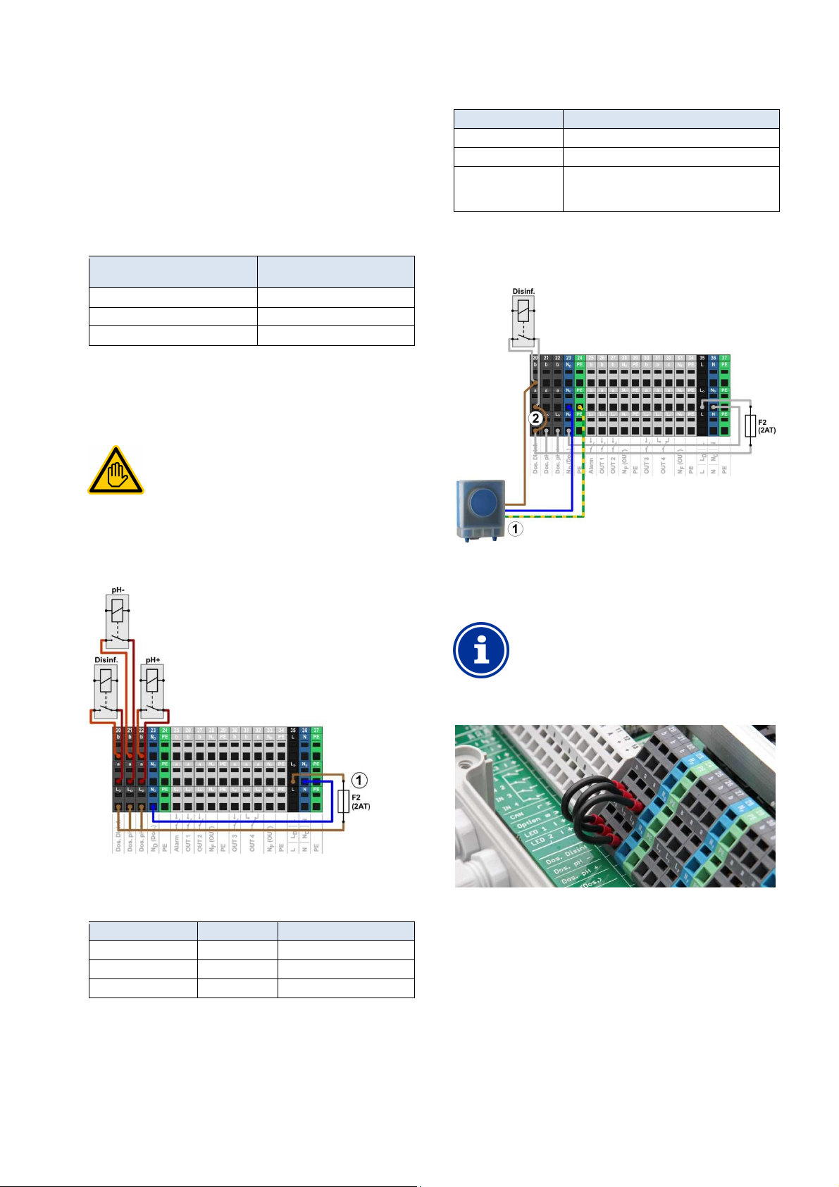
41
The electrical connection for eco mode may only be
performed by an ELECTRICAL SPECIALIST as
pump's neutral conductor N and protective
earth PE can be connected to the terminal blocks
and PE as shown in the
Dosing pumps
41 Dosing pumps
41.1 Peristaltic pumps
The standard PoolManager® dosage pumps are so-called peristaltic
pumps. Rollers on the rotor continuously squeeze the dosage hose,
thereby providing for the dosing of maintenance products.
The pump's dosage hose is replaceable. The pump's dosing output
can be adjusted via various hose diameters.
The following table shows the standard dosing outputs on
PoolManager® dosage pumps.
Function Standard dosing hos
pH (pH minus / pH plus) 1.5 l/h
Cl (ChloriLiquid) 1.5 l/h
O2 (BayroSoft) 3 l/h
The pumps used are run with a 230V~ power supply. PoolManager®
control system periodically turns the dosage pumps on and off within a
fixed dosage cycle (typically 60s) in order to realise the dosing output
calculated. A higher dosing output will lead to longer turn-on times.
41.1.1 Electrical connection
Requisite user qualification:
ELECTRICAL SPECIALIST
(dosing output)
Each terminal block is set up as follows:
Terminal Function
b Working contact
a Centre contact
LD Supply phase 230VAC for dosing outputs.
Can be bridged to the centre contact if needed in
order to control 230VAC devices.
The following figure schematically shows the connection of a standard
dosage pump for 230V~. The pump is connected to the disinfection
dosage output. For pH- and pH+, connection is correspondingly on
terminal blocks [21] and [22], respectively.
defined in the chapter User qualification.
The following figure shows the internal wiring of the three dosing
outputs for disinfection, pH-, and pH+. All connections shown are run
internally as conductor paths.
1 Fuse 2AT for the 230V~ Phase L
The following terminal blocks are allocated to the dosing outputs:
for supplying dosing outlets
D
Dosing output Terminal block Function
Disinfection 20 NO switch
pH- (pH minus) 27 NO switch
pH+ (pH plus) 22 NO switch
Standard dosage pump 230V~
1
(peristaltic pump)
2 Wire bridge in the terminal box from phase LD to
centre relay contact a
INFO
Connection of neutral conductor N and PE
A dosage
intended for the purpose ND
figure.
Wire bridges in the terminal box from phase LD to the dosage outputs'
centre relay contact a
User Manual PoolManager® 75
Page 76
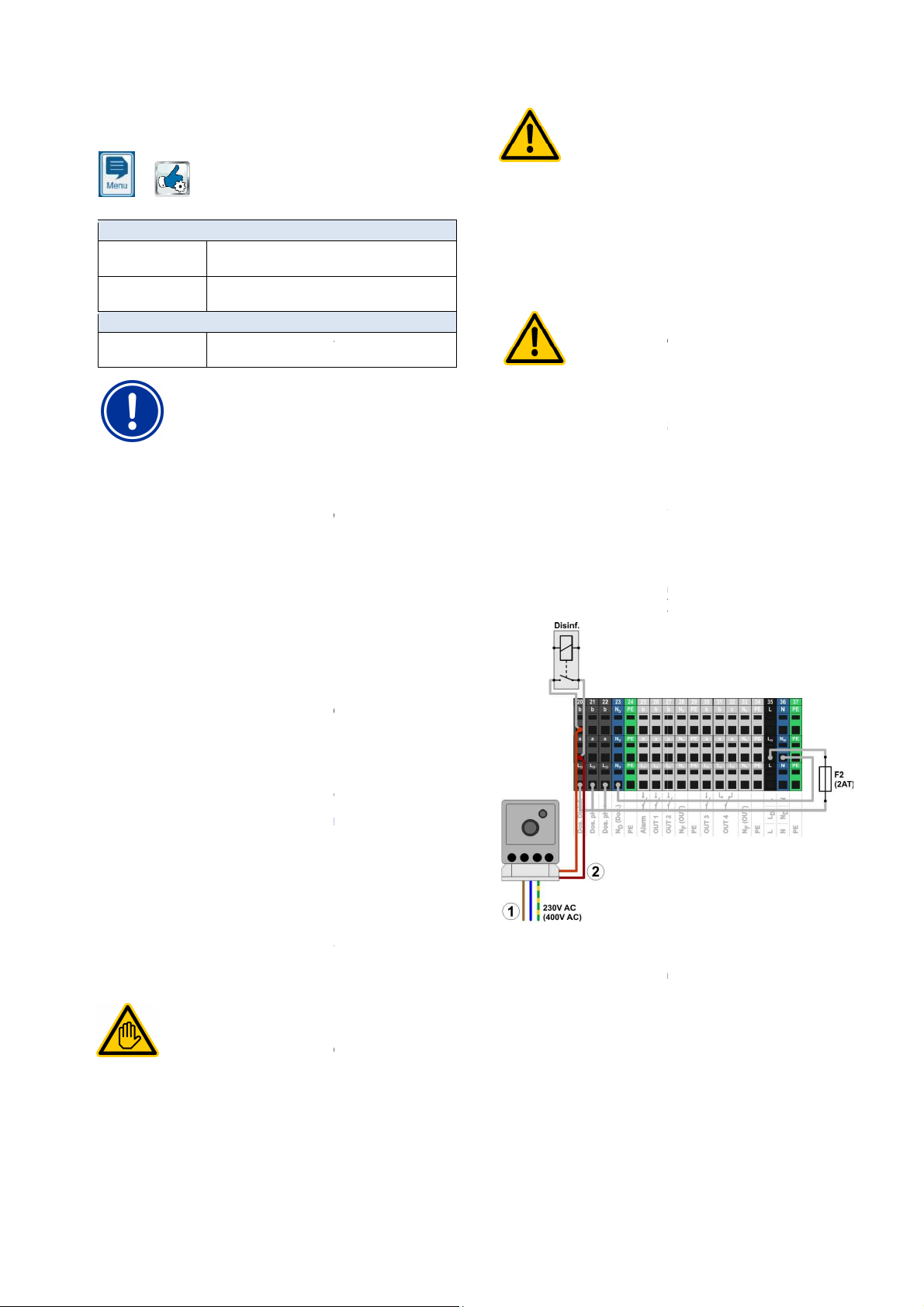
41
Configuration d
For peristaltic pumps, select
Select the hose used [l/h], or select the setting
if none of the hose configurations matches.
Enter the correct dosing output for the corresponding
Incorrect configuration of dosing output
If a pump's dosing output is not configured correctly,
then the following problems will arise:
The calculation for duration of manual dosing is not
The configuration assistant for configuring contro
parameters calculates erroneous settings.
The O2 (BayroSoft) dosing amounts are not correct
(overdosage or underdosage!)
possible to use membrane dosing pumps (magnet dosing
especially for higher dosing outputs in large pools. PoolManager
supports this pump type via special triggering with dosage pulses.
A membrane dosage pump generally has its own power connection
and is permanently connected to the power grid. When the pump is set
operating mode, individual pump strokes can be triggered
via an external potential free contact. Depending on the
and the settings, a certain amount of liquid is dosed on the pump.
supports the triggering of individual pump strokes.. A
maximum of 240 dosage pulses per minute can be emitted. This
and configured i
Configuration of dosing pumps
pumps
In principle, all pump types are suitable that allow triggering of
individual pump strokes via a potential free contact in
can trigger a maximum of 240
strokes/min. The switch duration of one dosing pulse is fixed to 125
For many pump types, the manufacturer offers a special trigger cable
for external triggering, which can be use
The electrical connection for eco mode may only be
performed by an ELECTRICAL SPECIALIST as
User qualification.
l
Destruction of control input via
The pump may be destroyed if the control input of a
membrane dosing pump is accidentally placed under
Potential consequence: Destruction of membrane
Be absolutely sure to connect the dosing output as
a potential free switch.
necessary, remove the wiring bridge between the
and a of the dosing output being used.
Jammed relays from switching the power supply on
membrane dosage pumps
Do not use turn membrane dosage pumps on and off
using their power supply
pump. Membrane dosage pumps at times draw
extremely high starting currents, which can lead to
jammed contacts on the dosing relays and therefore
lead to overdosage.
Potential consequence: Death or the gravest
heavy material damage.
Always trigger membrane dosage pumps potential
free via their control input.
The following figure schematically shows the connection of a
membrane dosage pump to a PoolManager
is connected to the disinfection dosage output. For pH
connection is on terminal blocks [21] and [22], respectively.
Membrane dosing pump's
external power supply
Membrane dosing pump's control input
dosing output (potential free switch contact)
, as is done with a standard
Dosing pumps
41.1.2 Configuration
You'll find all relevant setting in the menu
HAZARD!
230V~
Service functions
Menu Configuration dosage pumps
Pump type
pH / mV (Cl) / O2
Hose config.
pH / mV (Cl) / O2
For Hose config. only = manual
Pump output
pH / mV (Cl) / O2
Standard.
manual
dosage pump in [l/h].
IMPORTANT NOTICE!
•
correct.
•
•
41.2 Membrane dosing pumps
It's
osing pumps
pumps),
®
also
230V~.
dosing pump
•
• If
terminals LF
Hazard!
degree of injury,
•
®
dosing output. The pump
- and pH+,
to external
PoolManager®
operating mode can be activated
menu (Service functions
41.2.1 Suitable membrane dosing
operating mode. PoolManager®
ms.
PoolManager®.
41.2.2 Electrical connection
Requisite user qualification:
ELECTRICAL SPECIALIST
defined in the chapter
pump type
n PoolManager®
).
External
d for connection to
1
230V~
2
connected with the
User Manual PoolManager®
76
Page 77
42
After connecting one or multiple membrane dosing pumps, correct
and configured in PoolManager
Configuration dosing
will activate the triggering of
For membrane pumps, select
Enter the desired maximum number of strokes
[strokes/min] at a dosing output of 100%.
For more information, also review the section
Enter the correct maximum dosing output for the
dosing pump in [l/h]
(for the maximum number of strokes
Incorrect configuration of dosing output
If a pump's dosing output is not configured correctly,
then the following problems will arise:
The calculation for duration of manual dosing is not
parameters calculates erroneous settings.
Membrane dosage pump for O2 (BayroSoft)
For O2 dosing (BayroSoft), the pump type
cannot be selected. For BayroSoft
dosing, however, a membrane pump can be triggered
with simple turning on and off, like a peristaltic pump.
The output desired can be configured directly on the
This variation is sufficient, as PoolManager
doses either 100% or not at all. Therefore, variable
triggering of individual pump stro
The maximum number of strokes per minutes must be configured such
that the desired maximum output in l/h is yielded at 100% dosing
Output can be determined for certain stroke rates with the data sheet
the pump being used, such as for 60 strokes/min, 120 strokes/min,
For many pumps, stroke length can also be configured using a
controller on the pump. This also makes it possible to adjust the
A maximum pump output of 2.0 l/h is planned for a system. The
maximum stroke frequency on the pump is 180 strokes/min.
Using the pump's data sheet, the desired output of 2.0 l/h is yielded
with maximum stroke length (100%) and a stroke frequency of 40%,
Therefore, the maximum number of strokes must be set to 72/min in
in this case. Then PoolManager
dosing pulses per minuted at maximum dosing output (100%). This will
of 2.0 l/h.
for configuring control
always
Changing the maintenance program
The maintenance program (oxygen (02 / BayroSoft) / Chlorine (Cl) /
Bromine (Br)) is changed in the menu
care method
The new program that is desired and a matching code number has to
be entered for each. The code number depends on the previous
on the new maintenance program selected:
New program
PoolManager
PoolManager
PoolManager
PoolManager
PoolManager
PoolManager
Changing the maintenance program
41.2.3 Configuration
triggering has to be activated
You'll find all relevant setting in the menu
Service functions
Selecting the pump type Membrane pump
individual dosing strokes via PoolManager®.
The default setting for pump type is Standard.
intended for conventional peristaltic pumps.
Menu Configuration dosage pumps
Pump type
pH / mV (Cl) / Cl
Max. no. of strokes
pH / mV (Cl) / Cl
Determining output
Pump rate
pH / mV (Cl) / Cl
corresponding
IMPORTANT NOTICE!
®
menu.
pumps
This operating mode is
Membrane pump.
entered)
42
Menu hotkey
Service functions
Enhanced functions
maintenance program and
Configuration
Current program
PoolManager® O2
PoolManager® O2
PoolManager® Cl
PoolManager® Cl
PoolManager® Br
PoolManager® Br
Code number
®
Cl 122
®
Br 123
®
O2 221
®
Br 223
®
O2 321
®
Cl 322
•
correct.
• The configuration assistant
INFO
Membrane pump
pump.
41.2.3.1 Determining output
output.
for
or 180 strokes for min.
®
kes is not necessary.
pump's output to match needs.
Example:
i.e. 72 stokes/min.
PoolManager®
lead to the desired maximum dosing output
®
will generate 72
User Manual PoolManager®
77
Page 78
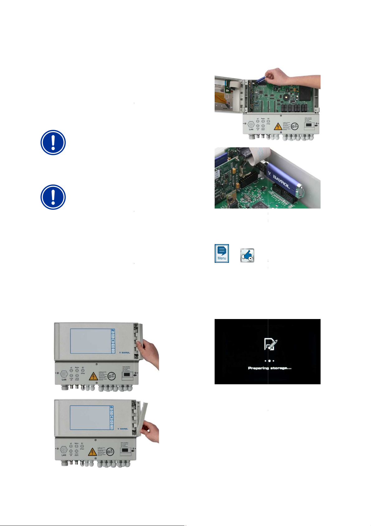
43
internal software (firmware) can be updated at any time
The most current software version will be available for download in the
All software is packed into one file (file size ca.
changes with each version and has the following format, for example:
4882.bin. In this example, 2.2.3 indicates the
Loss of power during software update
is continuously supplied
with power throughout the entire software update. If
there is a power outage during the updating process,
then the update will fail and will definitely have to be
the USB memory stick
USB interface supports hot plug & play,
i.e the memory stick can be plugged in during ongoing
However, it is expressly recomm
power supply when doing so. When
plugging in during ongoing operation
sensitive electronics to be damaged due
to electrostatic charges upon coming into contact.
Copy the file with the current software into the main direc
(root directly) on your USB memory stick (e.g.. M:
under any circumstances, copy the file to a sub
only searches for potential software updates in
casing as shown in the
ended to turn off
, it's possible for
Please the US memory stick with the sof
internal USB slot.
Close the front of the casing and turn the power supply back on.
edure is complete.
2 minutes.
Select the software update function in the menu as follows:
Service functions
Software update (from USB stick)
Start software update
automatically performs a restart in order to
launch the software update
The screen background is black throughout the update. There
are various icons and text messages to inform you about the
software update's progress.
The updating process takes abo
Once competed, PoolManager
restart and will boot with the updated software.
You can then remove the USB stick. T
voltage supply.
Software update
43 Software update
PoolManager®
using a standard USB memory stick.
retailer section on the BAYROL website.
firmware_PM5-2.2.3software's version number.
43.1 Step by step
IMPORTANT NOTICE!
Ensure that PoolManager®
25 MB). The file name
4.
PoolManager®
tware update into
repeated.
IMPORTANT NOTICE!
Plugging in
PoolManager®
operation.
PoolManager®
PoolManager®
1.
PoolManager®
the root directory.
2. Turn off PoolManager® power supply.
3. Open the front of PoolManager®
following figures.
\). Do not,
-directory, for
tory
5.
6. Wait until the boot proc
This takes ca. 1 -
7.
8. Press the button
9. PoolManager®
10.
11.
12.
PoolManager®
User Manual PoolManager®
ut 5 minutes.
®
will perform an automatic
o do so, turn off
78
Page 79
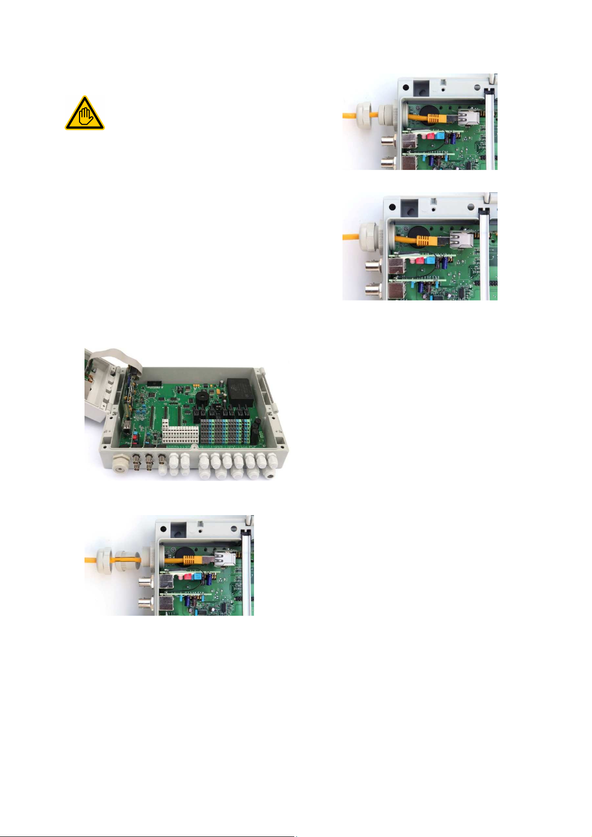
44
The network connection may only be performed by an
User
Network connection
44 Network connection
Requisite user qualification:
IT SPECIALIST
IT SPECIALIST as defined in the chapter
qualification.
PoolManager® offers comprehensive and very comfortable
opportunities for remote access from a local network or from the
Internet.
In order to use these opportunities, PoolManager® has to be
connected to a TCP/IP network (TCP/IP is the transmission protocol
used on networks and the Internet).
In the PoolManager® terminal box, there is a standard Ethernet slot
(RJ45). A standard network cable (Cat5 or Cat6) can be plugged
into that slot.
The network cable is fed through a special large cable fitting into the
terminal box in order to maintain IP65 rating.
8. Press the rubber seal into the cable fitting.
44.1 Step by step
1. Turn off PoolManager® power supply.
2. Loosen the four screws on the terminal box cover and remove
it.
3. Loosen the large cable fitting on the far left.
4. Feed a standard network cable with an RJ45 plug into the
terminal box as shown in the following figures.
9. Screw the cable fitting tight again in order to obtain a reliable
seal.
10. Close the casing again. Tighten the screws on the terminal box
cover by hand in order to obtain a reliable seal.
11. Turn PoolManager® voltage supply on again.
5. Next, run the cable through the cable fitting's cover and through
the fitting itself.
6. Plug the cable into the RJ45 slot.
Be sure the plug connection locks securely
7. Pull the slotted rubber seal over the cable as shown in the
figure.
User Manual PoolManager® 79
Page 80
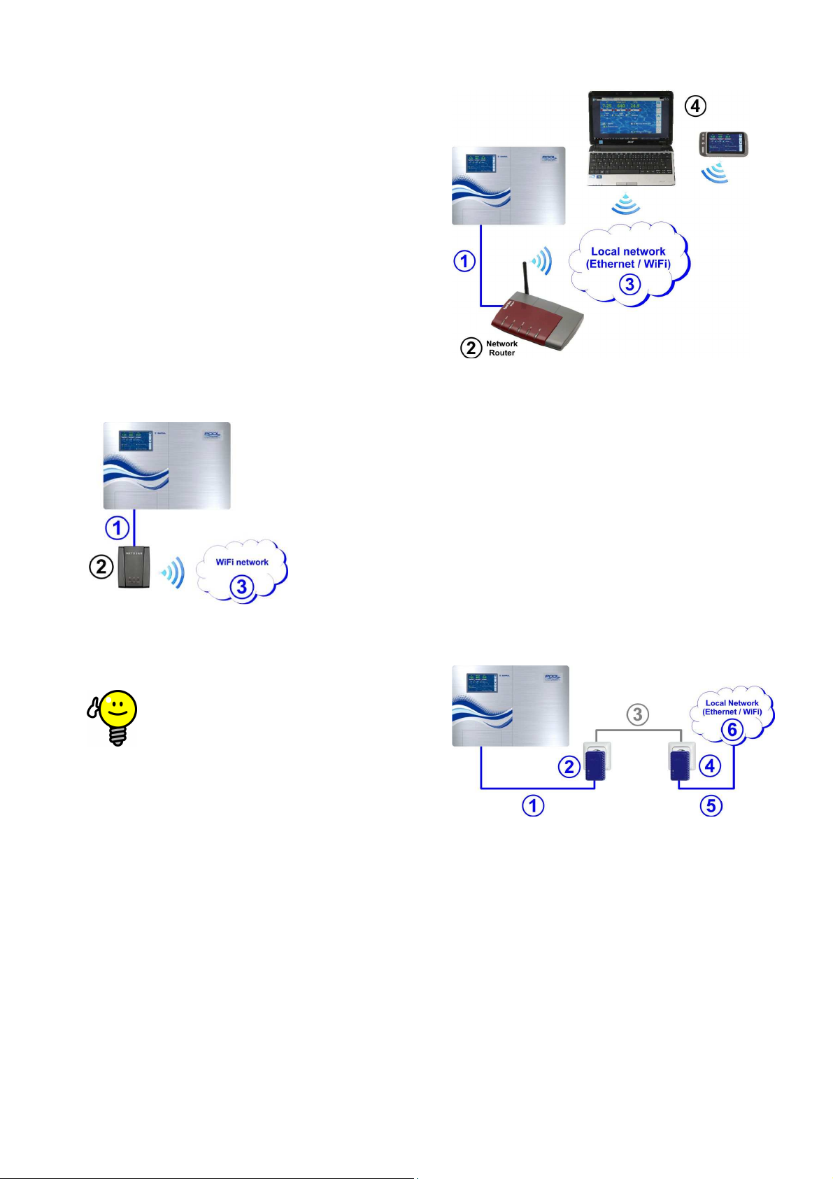
44
If there are poor reception conditions at the site where
is installed, then you can use a (long)
and
the wireless adapter to install the wireless adapter at a
Network connection
44.2 Options
44.2.1 Wireless network (WLAN / WiFi)
44.2.1.1 PoolManager® wireless connection
It is easy to integrate PoolManager® into an existing wireless network.
To do so, you'll need a wireless network adapter (also known as
WLAN adapter or WiFi adapter). These kinds of adapters can be found
for reasonable prices at specialised shops. One example of a current
model would be the Wireless Internet Adapter (WNCE2011) from the
manufacturer Netgear.
The adapter is connected with PoolManager® using a standard
network cable and establishes a transparent data connection from
PoolManager® to the existing wireless network.
The wireless adapter has to be configured in advance just one time so
that it can establish the connection to the desired wireless network
automatically. That basic configuration is usually done with the help of
a PC. Please refer to the documentation of the wireless adapter being
used for more details.
The following figure schematically shows a connection between
PoolManager® and a wireless network.
1 Standard network cable (Ethernet)
2 Network router with wireless network (WLAN)
3 Local network (wireless and / or Ethernet)
4 PCs and mobile devices on the local network have remote
access to PoolManager®
1 Standard network cable (Ethernet)
2 Wireless network adapter (WLAN / WiFi adapter)
3 Wireless network
TIP
Poor reception conditions
PoolManager®
standard network cable between PoolManager®
location with good reception conditions.
44.2.1.2 Access via a wireless network
If there is no wireless network present into which PoolManager® can
be integrated, then it is easy for you to set up a network in order to, for
example, access PoolManager® wirelessly using your mobile devices.
To do so, you need a standard network router with an integrated
wireless network (WLAN / WiFi). PoolManager® connects to the
network router via network cable, wireless adapter, or PowerLAN. PCs
and mobile devices can also connect with the network router via
network cable or wireless network, thereby acquiring remote access to
PoolManager®.
The network router has to be configured by an expert once upon being
used for the first time. Please refer to the documentation of the
network router being used for more details.
The following figure schematically shows the set-up for this kind of
network.
44.2.2 PowerLAN (dLAN)
PowerLAN technology (also called dLAN (direct LAN) or Powerline
Communication (PLC)) uses the building's 230V~ system for setting
up network connections. Data are transmitted using the existing power
lines.
With the corresponding PowerLAN adapters, which are available from
specialist shops, a network connection can be set up between two
normal wall plugs.
In many cases, PowerLAN technology represents an interesting option
for integrating PoolManager® into an existing network.
The following figure schematically shows an example of this kind of
system:
1 Standard network cable (Ethernet)
2
Plug with PowerLAN adapter
3
The building's existing 230V~ power network
4
Plug with PowerLAN adapter
5 Standard network cable (Ethernet) as a connection to the
local network (e.g. to the network router).
6 Local network (wireless and / or Ethernet)
User Manual PoolManager® 80
Page 81
45
Remote access to the local network
Configuration of remote access from the local network
must be performed by an IT SPECIALIST as defined in
This section describes the requisite configuration steps to facilitate
local (TCP/IP) network.
In a TCP/IP network (Ethernet and/or wireless network), each device
has to receive a unique IP address with which it can be accessed.
TCP/IP is the designation of the standardised transmission protocol on
the Internet and on local networks
(TCP = Transmission Control Protocol, IP = Internet Protocol).
The first section is the network ID, which is identical for all
is the host ID, which is issued only one time
within a network and accesses a specific device.
An IP address always consists of a series of four numbers separated
by a dot. Each number can have a value between 0 and 255
Network ID and host ID for IP addresses
In most networks, the IP address is broken down as
The first three numbers are the network ID
The fourth number is the host ID
There are exceptional cases with different breakdowns,
network ID and two for the
The corresponding breakdown is determined by the
network's subnet mask, which also consists of a series
of four numbers. Each number of a subnet mask
generally has the value of either 255 or 0. 255
onding positions as part of the
network ID. That is why the subnet mask has the value
255.255.255.0 on most networks.
networks are 192.168.x
(x = 0, 1, 2, ...). The host ID can be in the range of 1...254. The host
IDs 0 and 255 are reserved for special purposes. The host ID 1 is
In a network with the network ID 192.168.0, t
into a local network, its IP
IP address has to be within the permissible range
For example, if the network router's IP address is 192.168.1.1,
must obtain a free network addr
range 192.168.1.2 ... 192.168.1.254.
The IP address that PoolManager
the network, i.e. it may not yet be used by another network device.
addresses already occupied can usually be found
configuration (see router documentation).
Determining network
You can find your network's network
router's configuration (see router documentation).
Alternatively, you can also used a (Windows
the network to determine
search
the Windows start menu, enter
An input window will open
There, enter the command
Your PC's network settings are displayed:
IP address (or IPv4 address)
mask
Standard gateway
You can determine the network ID using the IP
address of the PC and of the subnet mask.
Checking an IP address via ping
search
the Windows start menu, enter
input window will open
By entering the command
whether an specific IP address is already being
used on the network.
For example,
there is a device that responds under the IP
address indicated.
is no response, then the IP
usually still available.
Network (IP) configuration
network (IP) configuration (IP = Internet
Communication & interfaces
Network (IP) configuration
ID in your network
)PC on
field (magnifying glass symbol) in
, and press
field (magnifying glass symbol) in
, and press
, you can check
checks whether
address is
Remote access to the local network
45
Requisite user qualification:
IT SPECIALIST
the chapter User qualification.
45.1 Overview
remote access to PoolManager® from a
45.2 Local network (IP) address
An IP address consists of two sections:
1.
devices within the same network.
2. The second section
(e.g. 192.168.1.100).
INFO
follows:
•
•
e.g. two numbers for the
host ID.
•
then PoolManager®
•
®
uses must still be available on
A list of the IPin router
TIP
-ID
the network ID:
• Go to the
enter
•
•
•
ipconfig
•
• Subnet
•
•
TIP
• Go to the
enter
• An
•
ping
ping 192.168.1.88
• If there
ess in the
-
-
cmd
cmd
-
-
designates the corresp
Example:
Subnet mask 255.255.255.0
IP address 192.168.1.100
Network ID 192.168.1
Host ID 100
The most common network IDs for home
frequently used for the network router.
Example:
available is
• 192.168.0.1…192.168.1.254
In order to integrate PoolManager®
has to be properly configured for the network.
• PoolManager®
for the respective network. PoolManager
ID assigned by the network.
he IP-address range
-address
®
has to use the network-
45.3 Menu
You can reach PoolManager®
Protocol) as follows:
Menu hotkey
User Manual PoolManager®
81
Page 82
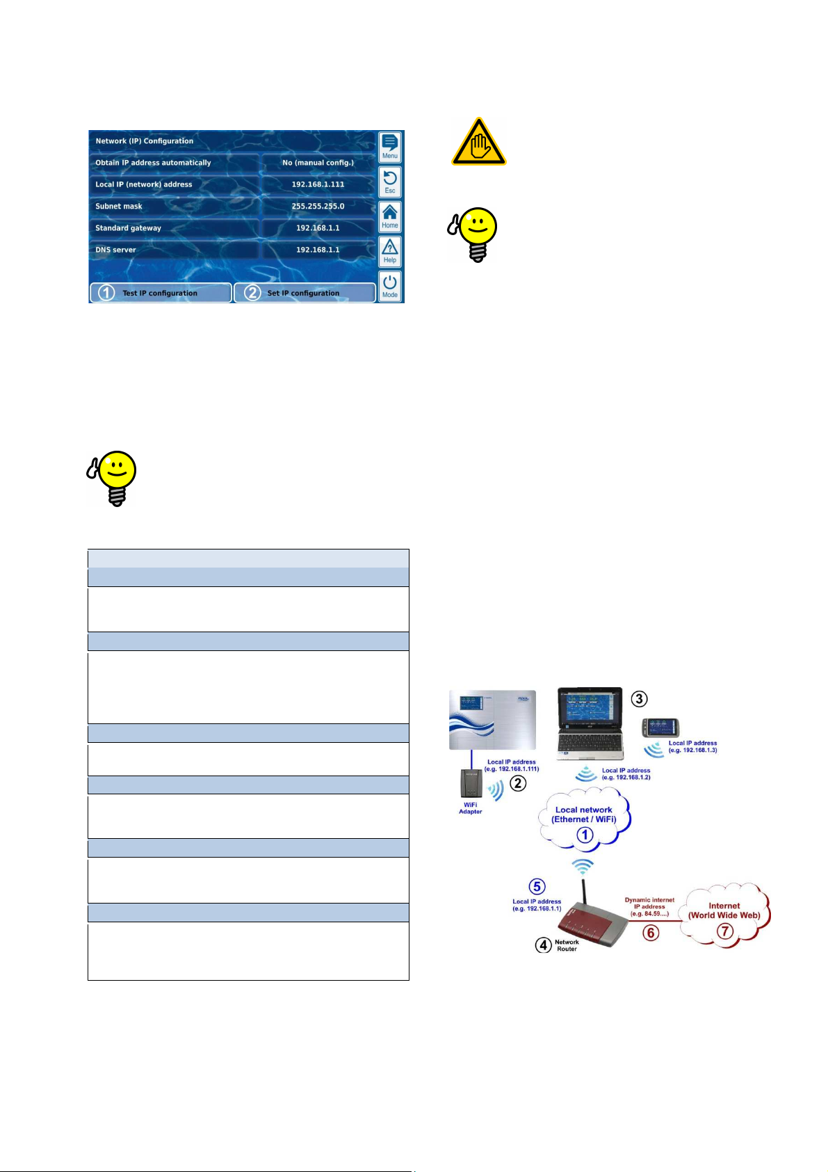
46
activating the IP
configuration. This helps to recognise and remediate
Configuration of remote access from the Internet must
be performed by an IT SPECIALIST as defined in the
Setting up remote access via the Internet does not
represent a challenge for an IT specialist and should be
founded IT
up can take a very long time or even be a
lete failure. Additionally, security against
That is why remote access via the Internet should
Remote access from the Internet
The following parameters can be configured in Network (IP)
configuration:
1 Test IP configuration
This function tests the current network configuration based
on various criteria and then issues a success or error
report.
2
Activate IP configuration
This function activates the current network settings. If the
function does not trigger, then the network settings will be
activated upon the next system boot.
TIP
Test IP configuration
Always run the test function prior to
potential problems.
Menu Network (IP) configuration
Assistant for automatic network (IP) configuration
This assistant automatically determines a suitable network configuration,
which you can then store permanently.
Follow the instructions on the screen.
Source IP address automatically
Fixed to no (manual config.) .
For automatic IP address sourcing via DHCP protocol, the problem would be
they it wouldn't be known initially and then could change again. However, the
IP address has to be known for remote access to PoolManager®. Therefore,
the IP address has to be entered manually and will therefore be known.
Local IP (network) address
Here, enter the desired IP address for your PoolManager® as described in the
previous section Local network (IP) address.
Subnet mask
The subnet mask generally retains the standard value 255.255.255.0.
The subnet mask only has to be adjusted if your network is using a different
breakdown between network-ID and host-ID.
Standard gateway
In general, the IP address is entered here for the network router to which
PoolManager® is connected. On many networks, the router has host-ID 1; but
that does not have to be the case.
DNS server
The DNS server (Domain Name Server) translates URLs (e.g.
www.bayrol.de) into the respective IP addresses on the Internet.
In general, the network router usually assumes this task, i.e. you enter the IP
address of your network router here as well.
46 Remote access from the Internet
Requisite user qualification:
IT SPECIALIST
chapter User qualification.
TIP
Set-up by an IT specialist
taken care of quickly. However, without wellexpertise, setcomp
unauthorised access can be compromised.
always be set up by an IT specialist.
To access PoolManager® from the Internet, you first have to integrate
it into your local network as described in the previous chapter Remote
access from the local network.
If the local network has a connection to the Internet, then remote
access to PoolManager® from the Internet can be set up. The local
network's Internet connection is generally realised via the network
router, e.g. via a DSL connection to an Internet service provider.
However, in order to facilitate remote access from the Internet, there
are several preparations to be made.
Initially, PoolManager® is not connected to the Internet. Rather, only
the network router is. The router has its own unique IP address on the
Internet. That IP address is not identical to the router's IP address on
the local network. Thus, the router has two different IP address, one
on the local network (such as 192.168.1.1) and one on the Internet
(such as 84.59.41.24).
By contrast, PoolManager® and other devices on the local network
possess only one local IP address. They do not have their own IP
address on the Internet.
The following figure schematically shows a local network with an
Internet connection via the router.
1 Local network (Ethernet and / or wireless network)
2 PoolManager® with wireless connection to the router
(or, alternatively, via network cable)
3 Further devices on the local network
(PCs and mobile devices)
4 Network router
User Manual PoolManager® 82
Page 83

46
If your network router has a static IP address on the
Internet, then there is no need to set up a DynDNS
Remote access from the Internet
5 Router's IP address on the local network
6 Router's Internet connection
(with separate IP address on the Internet)
7 Internet (World Wide Web)
The network router receives its IP address on the Internet from the
Internet service provider. In most cases, this address is dynamic, i.e. it
can change at any time, such as due to a reboot of the Internet
connection. This is designated a dynamic IP address.
Internet services providers also issue static IP addresses, which do
remain the same. However, to do so, special service packages with
static IP addresses have to be booked. Most standard DSL packages
work with dynamic IP addresses.
46.1 Dynamic IP address resolution
For remote access to PoolManager® from the Internet, you'll need your
router's current IP address on the Internet. If a dynamic IP address is
being used, then it won't be known initially.
The DynDNS system (or DDNS (dynamic Domain Name System
entry)) resolves this problem. These are services on the Internet (Web
services) to which your router regularly transmits its current IP
address. The DynDNS service provides you with a URL (such as
http://myPoolManager.dyndns.org). When you call up that URL from a
browser, the DynDNS service automatically forwards the query to the
current IP address of your network router. In this manner, you have
access to your network router at all times, even if it is using a dynamic
IP address.
46.2 Step by step
INFO
Static IP address
service.
46.2.1 DynDNS account set-up
Select a DynDNS provider and set up an account. This is done via the
DynDNS provider's website.
In general, the following data have to be entered:
• Username
• Password
• E-mail address for confirming the account
• Host name
The host name determines the URL you use to access your
PoolManager®: It generally consists of two sections:
1. A freely selectable name, such as myPoolManager®
(the name selected has to be available still)
2. A fixed extension issued by the DynDNS provider, such as
dyndns.org, dtdns.net, no-ip.com,... Some providers have
various extensions available.
An example of a complete URL for remote access would then be:
http://myPoolManager.dtdns.net
DynDNS providers with free services include, for example, dtdns.net
or no-ip.com. For a detailed description on setting up a DynDNS
account, please refer to the documentation from the respective
provider.
46.2.2 DynDNS configuration on a network router
Now you'll have to activate the network router's DynDNS function. This
ensures that the router regularly transmits its current IP address to the
DynDNS service.
Most modern network routers support the DynDNS function. Should
your router not support this function, then we recommend replacing
the router.
The DynDNS function is generally configured by entering information
about your DynDNS account:
• Username
• Password
• Host name
The exact configuration procedure is heavily dependent upon the
router used. Generally, the router has either a Web interface for
configuration or a special configuration program.
You'll need the access data (username and password) for accessing
router configuration.
For a detailed description, please refer to the documentation for the
router being used.
46.2.3 Port forwarding on the network router
For remote access to PoolManager®, you'll still need to set up portforwarding on the network router. Port forwarding ensures that the
router forwards the respective queries from the Internet to
PoolManager®.
Remote access to PoolManager® is realised via the standard HTTP
port 80. The port accesses the data recipient, which in this case is
PoolManager® web server.
Therefore, port forwarding must be set up as follows:
• Port 80 forwarded to PoolManager® IP address on the local
network.
• If applicable, port 80 should be entered as the destination port.
Nearly all modern network routers offer the capacity to set up port
forwarding.
For a detailed description, please refer to the documentation for the
router being used.
46.3 Prerequisites and potential problems
Requirements for the web browser used
• Support for the current HTM5 standard
• JavaScript activated (it usually is)
Requirements for the network router
• Port forwarding
• DynDNS function
(Only when using a dynamic IP address)
• External access to port 80 may not be blocked
• The router must be configured such that it is permanently
connected to the Internet. If it is not connected, then remote
access will not be possible.
Requirements for the Internet Service Provider
• Contract terms and conditions may not prohibit operation of a web
server
• You need a public IP address, i.e. your network router's IP
address must be visible on the Internet. For some wireless
contracts (e.g. LTE without telephony), you are not issued a public
IP address. Operating a web server is not possible with that type
of contract. A public IP address is generally a dynamic IP address
that can change at any time. Unchangeable IP addresses are
designated as static or fixed.
• The Internet service provider has to permit access to port 80
User Manual PoolManager® 83
Page 84

47
Some Internet service providers block access to the
standard HTTP port 80. In that case, port 55555 can be
Port forwarding on the pouter has to be set up
In the browser, you simply need to add the port to the
he port is separated with a colon,
Despite the highest security standards, there is
fundamentally a residual risk for potential unauthorised
releasing remote access. Unauthorised
Security for remote access
TIP
Alternative port 55555
used, which PoolManager® offers as an alternative.
accordingly for port 55555.
IP address or URL. T
such as
http://myPoolManager.dtdns.net:55555 or
http://192.168.1.99:55555
46.4 Multiple PoolManagers® on one network
If there are multiple PoolManagers® running on one network, then
each device will be given its own IP address. Remote access from the
local network is realised via the corresponding IP address.
For remote access from the Internet, however, direct access of the
various IP addresses is not possible.
Instead, external access can be realised various ports, which the
router forwards to the individual devices' IP addresses.
Example:
PoolManager® 1
• IP address 192.168.1.88
• External access via port 80 (standard port), for example:
http://myPoolManager.dtdns.net
(standard port 80 does not have to be indicated in the URL)
• Port-forwarding on the router:
Port 80 192.168.1.88:80
PoolManager® 1
• IP address 192.168.1.99
• External access via Port 81, for example:
http://myPoolManager.dtdns.net:81
• Port-forwarding on the router:
Port 81 192.168.1.99:80
HAZARD!
Unauthorised access
access when
access can lead to dangerous configurations.
Potential consequence: Death or the gravest
degree of injury, heavy material damage.
• Do not use trivial
usernames or passwords
• Handle usernames and especially
passwords strictly confidentially
• Restrict user rights for remote access according to
your individual security needs in
a sensible manner.
• Only release remote access for the user level
actually needed.
• Where possible, use remote access on the local
network only and secure it against unauthorised
access via the standard measures.
• Where possible, use additional security standards
for Internet remote access, e.g. VPN
(virtual private network)
47 Security for remote access
In order to guarantee maximum security, remote access is equipped
with comprehensive security mechanisms:
• Data transmission in remote access is encrypted
(SSL encryption)
• Login with username and password is required
• Supplemental access code necessary
in order to modify parameter settings
• The default setting is for remote access to be deactivated
• User rights for remote access can be configured individually
• It is possible to assign different rights for Internet access and for
access from the local network
When security requirements are particularly high, established IT
concepts can be applied, such as VPN (virtual private network).
Consult an IT specialist as needed.
User Manual PoolManager® 84
Page 85
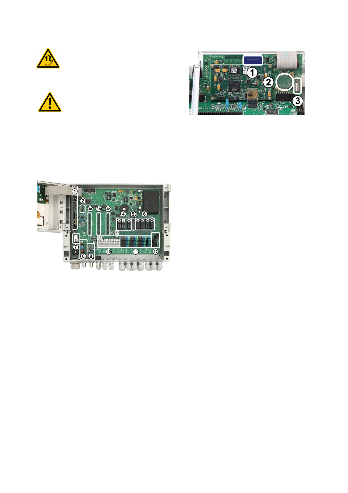
48
Electrical connections and all further activities
described in this chapter may only be performed by
ELECTRICAL SPECIALISTS as defined in the Chapter
When working on an uncovered unit, electrostatic
ronic
Hardware description
48 Hardware description
Requisite user qualification:
ELECTRICAL SPECIALIST
48.2 CPU printed circuit board
User Qualification.
HAZARD!
Electrostatic charges
charges can lead to damage to the sensitive elect
components on PoolManager®.
Potential consequence: Defective or erroneous
functions in PoolManager®.
• Ground whenever possible while working on an
uncovered unit.
• Avoid touching electronic components
unnecessarily.
48.1 System printed circuit board
1 SD memory card (must always be plugged in!)
2 CR2032 lithium battery
(Buffering for real-time clock)
3 USB socket for connection USB memory sticks
1 CPU printed circuit board
2 Configuration module (stored device configuration)
3 Three expansion plugs for supplemental modules
4 Three dosing relays (socketed)
a Disinfection
b pHc pH+
5 Alarm relay
6 Four relays for supplemental functions (socketed)
a OUT 1 (NO contact)
b OUT 2 (NO contact)
c OUT 3 (NO contact)
d OUT 4 (changeover contact)
7 Network socket Ethernet / RJ45
8 pH module (measuring and level monitoring)
9 Redox module (measuring and level monitoring)
10 Connection terminals of low voltage
11 Connection terminals for 230V~
12 Fuses
User Manual PoolManager® 85
Page 86
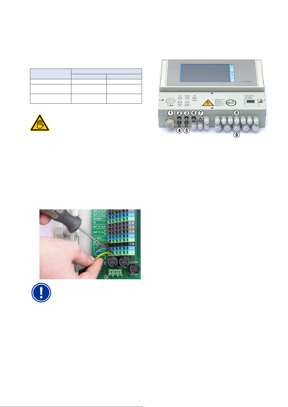
48
Electrical connections may only be performed by an
ELECTRICAL SPECIALIST as defined in the chapter
To avoid damage, do not apply any excessive force on
Hardware description
48.3 Connection terminals for spring contacts
48.3.1 Technical data
All connection terminals have so-called spring contacts.
Connection terminals are designed for the following conductor crosssections:
Cable type Conductor cross-section [mm²]
min. max.
fixed 0.2 2.5
Flexible
(no wire end ferrule)
Flexible
with wire end ferrule
48.3.1.1 Connect cable
Requisite user qualification:
ELECTRICAL SPECIALIST
User qualification.
Spring contacts can be opened with a simple screwdriver in order to
connect a cable:
1. Insert a matching screwdriver into the aperture above the
terminal as far as possible.
2. Gently pull up on the screwdriver's handle. This lever effect
pushes the screwdriver's tip down, thereby opening the spring
contact.
3. Once the spring contact is open, insert the cable into the
terminal.
4. Pull out the screwdriver.
5. Check that the cable is sitting securely by pulling on it lightly.
IMPORTANT NOTICE!
Force application on connection terminals
0.2 1.5
0.25 1.5
48.4 Electrical connections
48.4.1 External connections
1 Cable aperture for network cable
2 pH electrode
3 Redox (mV) electrode
4 Level monitoring pH (suction lance)
5 Level monitoring redox (mV) / Cl (suction lance)
6 Input IN 1 or flow monitor
7 BNC connection for free chlorine measurement (optional)
48.4.1.1 Cable fittings
8 11 small cable fittings
(for cable diameters 3 mm - 6.5 mm)
9 5 large cable fittings
(for cable diameters 5mm - 10mm)
All cables are inserted into the terminal box via cable fittings. Proceed
as follows:
1. Loosen the nut on the cable fitting such that it is barely on the
thread. You can also take it off completely.
2. Remove the seal plug.
3. Insert the cable through the nut and
cable fitting and into the terminal box.
4. Connect the cable..
5. Tighten the nut (but not forcefully) in order to ensure a reliable
seal.
the terminal using the screwdriver.
User Manual PoolManager® 86
Page 87
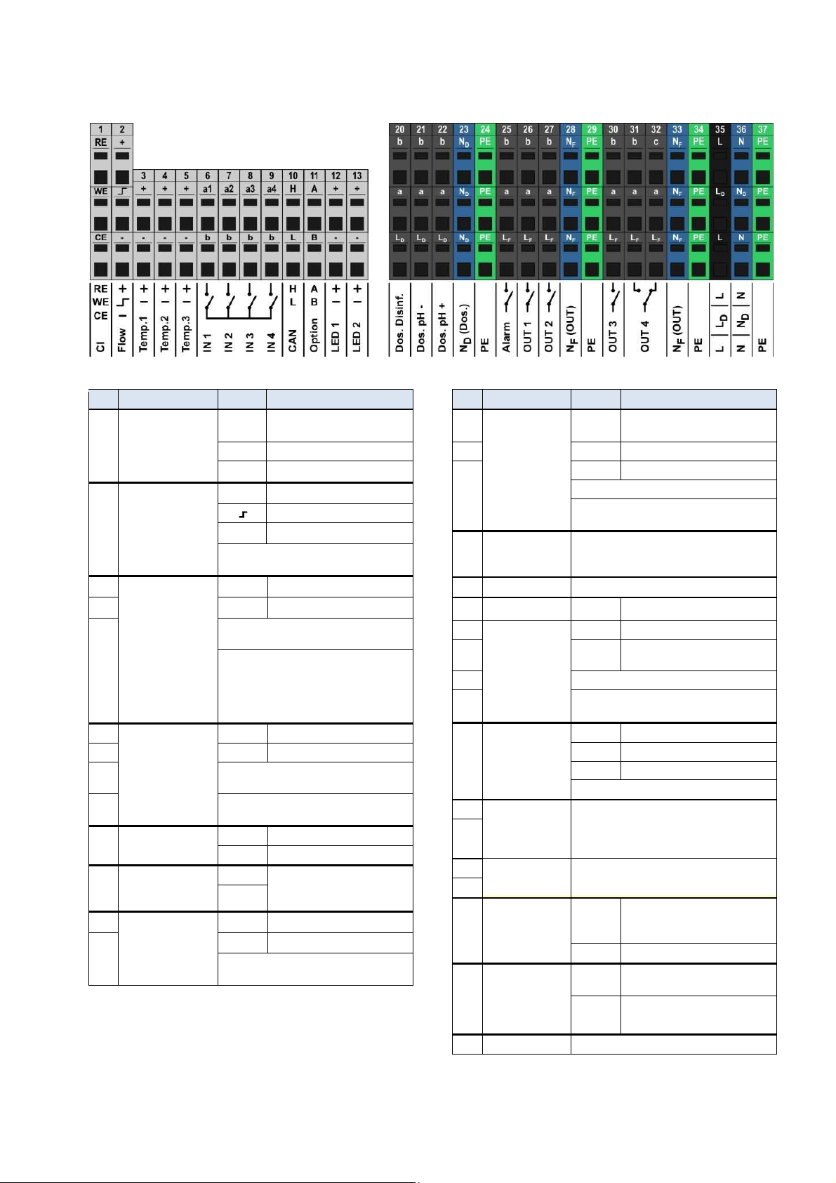
48
Hardware description
48.4.2 Connection terminals
48.4.2.1 Connection terminals of low voltage
No. Function Terminal Notes
1 Potentiostatic chlorine
measurement
(ANALYT and
PoolManager® PRO
only)
2 Flow switch
(inductive proximity
switch
"OMRON")
3 Temperature inputs
1 / 2 / 3
4
5 Temp. 1 / 2 0..50°C (820..1200Ω)
6 Universal switch
inputs
7 b Ground (GND)
IN 1 / IN 2 / IN 3 / IN 4
8 For connecting potential free external
9 IN 1 can optionally be used for flow
10 CAN-Bus H CAN High
11 Option A These terminals are connected
12 LED 1 / LED 2
13
RE Reference electrode
(Ag/AgCl)
WE Working electrode (gold)
CE Counter electrode (platinum)
Supply voltage
+
Signal output
Ground (GND)
-
During flow, the signal output
is switched to GND
Measurement input
+
Ground (GND)
-
Temp. 3 0..75°C (820..1400 Ω)
Sensor types supported:
• PT1000
• KTY83
• KTY16-6
(Parallel resistance 2kΩ required!)
a1/2/3/4 Signal input
switches or switch contacts.
monitoring.
L CAN Low
with expansion plugs and
B
reserved for future functions.
5V with 50Ω series resistance
+
Ground (GND)
-
For connecting LEDs for lighting effects
(optional)
48.4.2.2 Connection terminals for 230VAC
No. Function Terminal Notes
20 Dosing outputs
• Disinfection
• pH-
21 a Relay centre contact
• pH+
22 LD Phase 230V~ for dosing outputs
23 Neutral conductor
ND for dosing
outputs
24 Protective earth PE All PE terminals are connected internally
25 Alarm relay b Relay working contact
26 Relay switch
outputs for
27 LF Phase 230V~ for alarm relay
supplemental
functions
30 Potential free switch contact between a and b.
OUT 1 / OUT 2 /
OUT 3 / OUT 4
31 Wiring bridge from LF to a
32 Relay switch output
OUT 4
Resting contact
28 Neutral conductor
NF for alarm relay
33
and supplemental
functions
29 Protective earth PE All PE terminals are connected internally
34
35 Input phase
230V~
36 Input neutral
conductor
230V~
b Relay working contact
(Dosing output)
Potential free switch contact between a and b.
Wiring bridge from LD to a
230V~ on working contact b
Neutral conductor ND is not internally connected
with neutral conductors NF and N!
a Relay centre contact
and supplemental functions
230V~ on working contact b
c Relay resting contact
a Relay centre contact
LF Phase 230V~1
OUT 4 inactive Contact a-c closed
Neutral conductor NF is internally connected
with neutral conductor N, but not with neutral
conductor ND!
L
(also LF)
(also NF)
PoolManager® supply, alarm relay,
and supplemental functions
(LF fused with 4AT)
LD Supply dosing outputs
N
PoolManager® supply, alarm relay,
and supplemental functions
ND Supply dosing outputs
37 Protective earth PE All PE terminals are connected internally
User Manual PoolManager® 87
Page 88
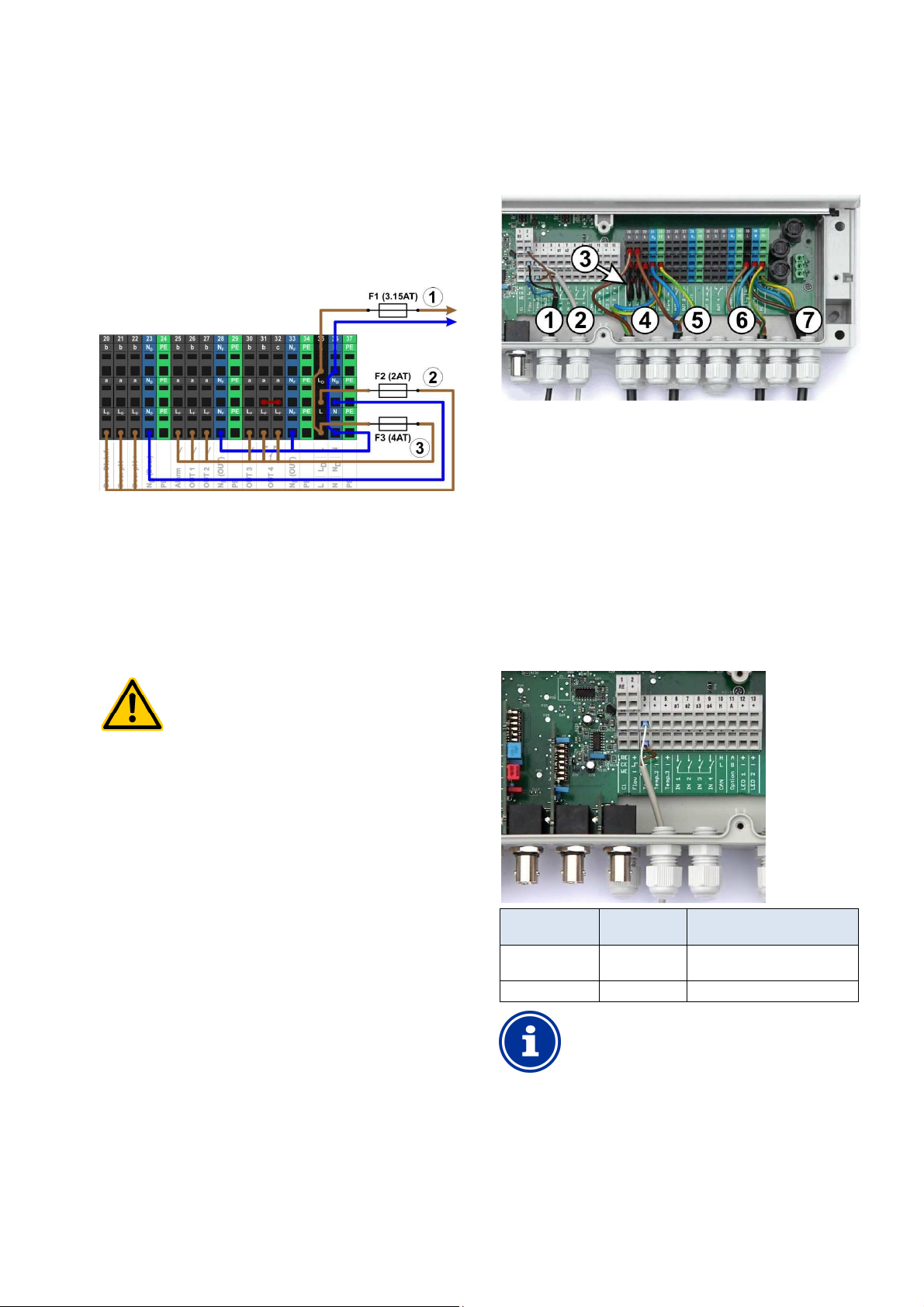
48
If the flow switch is stuck or experiences other types of
errors, there is a risk of dosing in standing water.
Poisonous chlorine gas can be yielded when
for the dosage
outlets if circulation is running under voltage
to the timer that
controls the filter pump, or use the corresponding
is controlling the filter pump
directly, then locking automatically occurs
Expansion temperature measurement range for
input Temp. 3 is designed for
temperatures from 0...75°C and is therefore particularly
Hardware description
48.5 Power supply 230V~
PoolManager® has three different branches for 230V~ supply:
• 230V~ supply for the PoolManager® unit
(L / N / PE, fuse F1 3.15AT)
• 230V~ supply for dosing outputs
(LF / NF / PE, fuse F2 2AT)
• 230V~ supply for alarm relay and supplement functions
(LF / NF / PE, fuse F2 2AT)
The following figure schematically shows the connections present on
the printed circuit board:
The supply for the PoolManager® unit as well as for the alarm relay
and the supplemental functions share a mutual power input (L/N).
Phase L for PoolManager® is run from the input over via fuse F1.
Phase LF for the alarm relay and the supplemental functions is run
from the input via fuse F3. Neutral conductors N and NF are
connected to each other internally.
Supply to the dosing outputs is run via a separate power input (LD /
ND). This input is fused via F2 and does not have an internal
connection to L / LF or N / NF.
HAZARD!
Gaseous chlorine produced from dosing in standing
water if dosage outlets are not locked.
48.6 Standard wiring
(Without supplemental functions)
The following figure schematically shows a typical PoolManager®
connection configuration.
1 Flow switch [terminal block 2]
2 Temperature sensor [3]
3 Wire bridges from LD to a for 230V~ dosing pumps
4 Dosing pump disinfection [20]
5 Dosing pH minus [21]
6 230 V~ power supply for dosing pumps
[LD / ND / PE], locks via the filter pump!
7 230 V~ power supply for PoolManager® , the alarm relay,
and supplemental functions [L / N / PE]
48.6.1 Connecting a temperature sensor
Also see the section Temperature measurement.
ChloriLiquid and pH minus come together.
Potential consequence: Death or the gravest
degree of injury,
heavy material damage.
• Only run power to input LD / ND
(dosage outlets locked via filter pump).
• Connect power input LD / ND
outlet on the filter pump.
• If PoolManager®
internally.
Terminal Function
[3+] / [4+] / [5+] Measurement
[3-] / [4-] / [5-] Ground Brown
input
(standard PT1000 sensor)
Cable colour
White
INFO
Temp. 3
Temperature
well suited for connection with a solar sensor.
Temp. 1 and Temp. 2 are designed for 0...50°C.
User Manual PoolManager® 88
Page 89
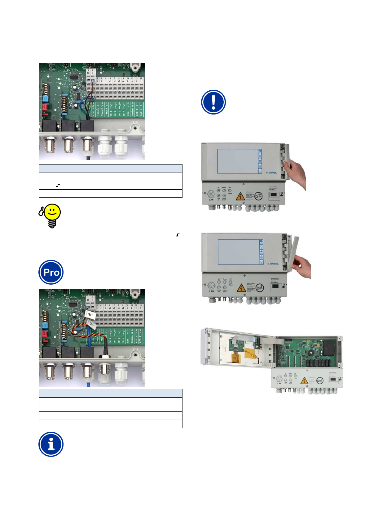
49
If a a simple reed contact or other potential free contact
proximity
]
RE and CE are connected to a BNC socket via adapter
cable. The chlorine measuring cell's glass electrode is
is a standard redox electrode
containing the reference electrode (RE) and the
The blue connection cable for the working electrode
(WE) is linked directly with the chlorine measuring cell's
Never open the casing on the left side, as damage may
Service measures on the unit
48.6.2 Connecting the flow switch
Also see the section Flow monitoring.
Terminal Function Cable colour
[2+] Supply voltage Brown
[2 ] Signal output Signal output
[2-] Ground (GND) Blue
TIP
Connecting a reed contact
is being used instead of an the inductive
switch, then it can be connected to the terminals [2
and [2-].
gold electrode.
49 Service measures on the unit
49.1 Opening the casing
IMPORTANT NOTICE!
Open on the right
otherwise occur.
1. Firmly press the hinge on the right side out and to the right.
2. Remove the cover plate and unhook the hinge on the bottom.
Always open on the right side!
48.6.3 Connection of chlorine measuring cell
INFO
This section applies for the model
PoolManager® PRO only.
Terminal Function Cable colour
[1 RE] Reference electrode
Signal output
(Ag/AgCl)
[1 CE] Counter electrode (platinum) orange
[1 WE] Working electrode (gold) Blue
INFO
Electrode connection
3. Swing the casing cover open to the left.
4. To close the casing, reverse this procedure.
49.2 Opening the terminal box
The terminal box cover is anchored by four screws. Loosen the four
screws and remove the terminal box cover.
When closing, tighten the screws enough that there is a reliable seal.
connected to it. This
counter electrode (platinum round end, CE).
User Manual PoolManager® 89
Page 90
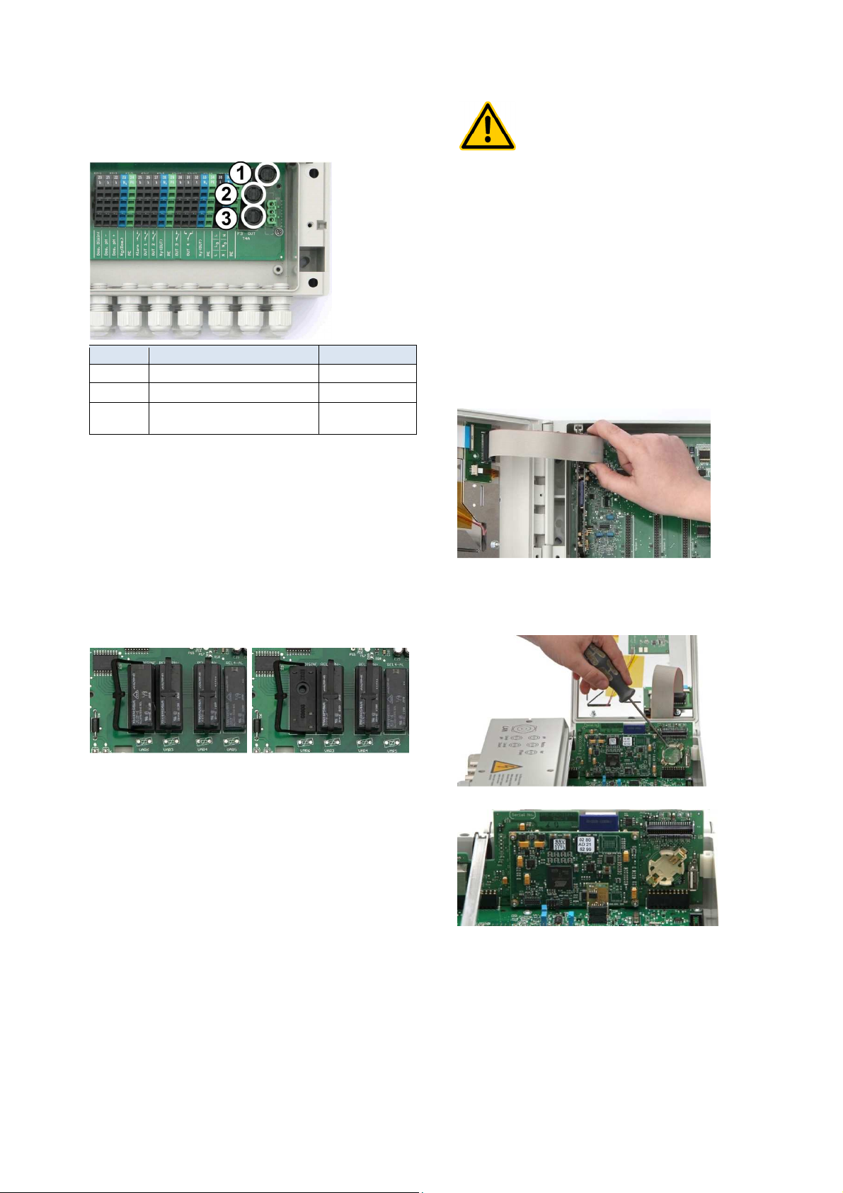
49
Service measures on the unit
49.3 Fuses
PoolManager® has three lead fuses on the branches of the 230V~
power supply; also see Power supply 230V~.
No. Function Default value
1 (F1) PoolManager® supply 3.15AT
2 (F2) Supply to dosing outputs 2AT
3 (F3) Supply to alarm relay
and supplemental functions
4AT
49.3.1 Fuse replacement
• Fuses are housed in a special mount and can be easily replaced.
• Use a matching screwdriver to gently press down on the fuse
mount's cover and turn to the left.
• The cover will spring open and you can replace the fuse.
• To close, set the cover along with the fuse onto the mount. Use
the screwdriver to gently press down and carefully turn to the right
until the cover clicks into place.
49.4 Replacing a relay
All relays (except the alarm relay, which is used little) are individually
socketed and can be replaced easily at any time.
HAZARD!
Potential malfunctions following battery alarm
Following a battery alarm, it's possible that
PoolManager® looses system time when the power is
turned off.
Potential consequence: PoolManager®
malfunctions
(e.g. incorrect dosing and switching times)
• If PoolManager® reports a battery alarm, replace
the buffer battery within max. 4 weeks.
• It may be necessary to supply PoolManager® with
constant 230V~ power so that the time is not lost.
The battery can be replaced as follows:
1. Turn off PoolManager® power supply.
2. Open the casing.
3. First loosen the flat ribbon cable for better access to the battery.
The plug has a lock, which you have to press to the side to
unlock.
4. Carefully push a flat screwdriver between the battery mount and
the battery.
5. Gently lift the battery out.
• The exact position of the corresponding relay can be found in the
section System printed circuit board or via the lettering on the
printed circuit board.
• First, swing open the plastic retaining bracket to the side.
• Carefully pull out the old relay.
• Carefully press the new relay into the socket.
• Then return the plastic retaining bracket to its original position.
49.5 Replacing the buffer battery
PoolManager® has a CR-2032 lithium battery, which is used for
buffering the real-time clock while the system is turned off.
This battery has a typical service life of at least 5 to 10 years.
PoolManager® reports a battery alarm when battery voltage drops
below 2.7V.
User Manual PoolManager® 90
6. Press the new battery into the battery mount such that the flat
side (+) is on top.
7. Plug the flat ribbon cable back in.
8. Close the front of the casing and turn the power supply back on.
Page 91
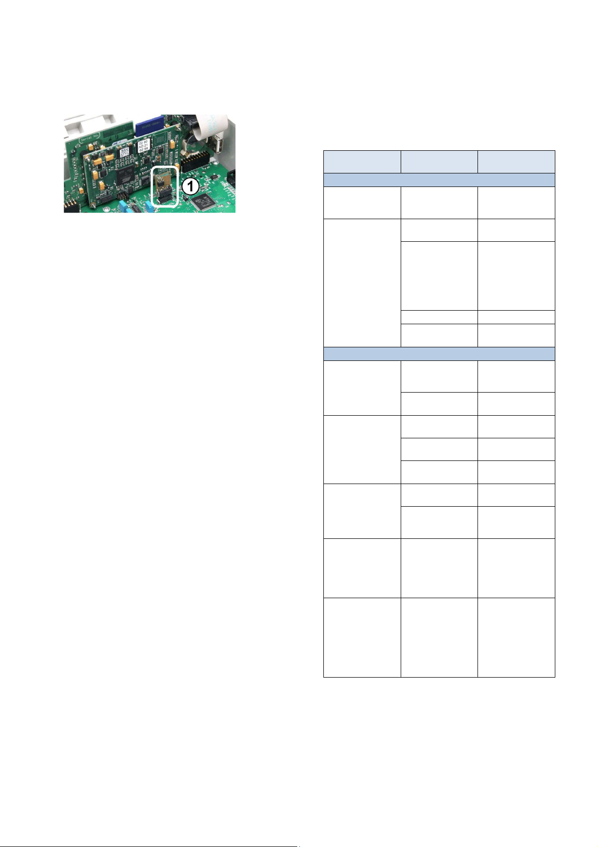
50
Dosing pump has sucked
Installation of optional supplemental modules
49.6 Replacing the configuration module
The configuration module stores PoolManager® device configuration:
Maintenance program, optional supplemental functions, etc.
The configuration module is plugged in to a plug socket, making it
easy to replace or to plug into another unit.
50 Installation of optional supplemental modules
50.1 4x power outputs 0/4...20mA:
PM5-SA4 CONVERTER 0/4-20MA (Art. no. 127011)
The supplemental module PM5-SA4 KONVERTER 0/4-20MA (Art. no.
127011) provides four outputs 0/4-20mA. A second module can be
added as needed, such that there is a total of four power outputs
available.
The module is simply plugged into one of PoolManager® three module
plugs and then configured in the menu.
The power outputs can be used for the following functions:
• Transmitting current measured values (pH, mV, temp.) as power
signal 0/4-20mA (for videographic recorders, remote displays,
building management systems)
• Triggering external systems
(e.g. variable filter pumps, salt electrolysis systems)
For more details, please refer to the separate documentation for the
PM5-SA4 CONVERTER 0/4-20MA (Art. no. 127011).
50.2 RS485 interface:
PM5-RS485 CONVERTER (127012)
The supplemental module PMS-RS485 CONVERTER (Art. no.
127012) provides a RS-485 data interface.
The module is simply plugged into one of PoolManager® three module
plugs and then configured in the menu.
• The RS-485 interfaces facilitates access to PoolManager® data
and statuses (alarms, etc.) (e.g. for building automation).
For more details, please refer to the separate documentation for the
PM5-RS485 CONVERTER (Art. no. 127012).
51 Troubleshooting
The following tables shows the typical problems that can arise when
operating PoolManager®. Potential causes and remediation measures
are indicated for each of the problems.
The table is broken down according to the modules pH, mV (redox),
O2 (BayroSoft), and temperature.
Type of problem Potential cause of the
pH measurement
pH control measurement
and unit display show
different values
Calibration failure in
pH calibration
pH control / pH dosing
The unit shows a dosing
output of 0% although
there is a deviation
between actual value
and setpoint
The dosing pump
continues to run despite
the unit showing a
dosing output of 0%
Dosing pump is running,
but there is no pH
correction
pH value fluctuating
around the setpoint
pH value deviates from
setpoint over a longer
period of time
problem
Calibration erroneous or
was a long time ago
Erroneous entry of
calibration values
Electrode contaminated
or defective
Moisture in cable Dry or replace cable
Measurement amplifier
defective
Dosing is blocked by an
alarm (flow, level, or
dosing time alarm)
Start delay still running Wait for end of start
Fuse on the dosing
pump is burnt
Dosing relay defective Replace the respective
Dosing pump defective Replace the dosing
Container is empty Replace maintenance
in air and is no longer
dosing
pH control dosing output
is too high
pH control dosing output
is too low
Remediation of the
problem
Perform a new
calibration
Repeat calibration
Use 5-10% hydrochloric
acid to clean the
electrode and then rinse
with distilled water. If the
electrode does not
calibrate after this, then it
has to be replaced.
Device has to be
repaired or replaced
Remediate alarm cause
Acknowledge alarm
delay
Replace fuse (2AT)
relay
pump
product
Remove air from dosing
head
Set a higher value for the
p-range, which will lower
dosing output.
Reducing the minimum
switch-on time hinders
overdosage.
Set a lower value for the
p-range, which will
increase dosing output.
An increase in minimum
switch-on time will result
in the setpoint be
approached more
quickly.
User Manual PoolManager® 91
Page 92
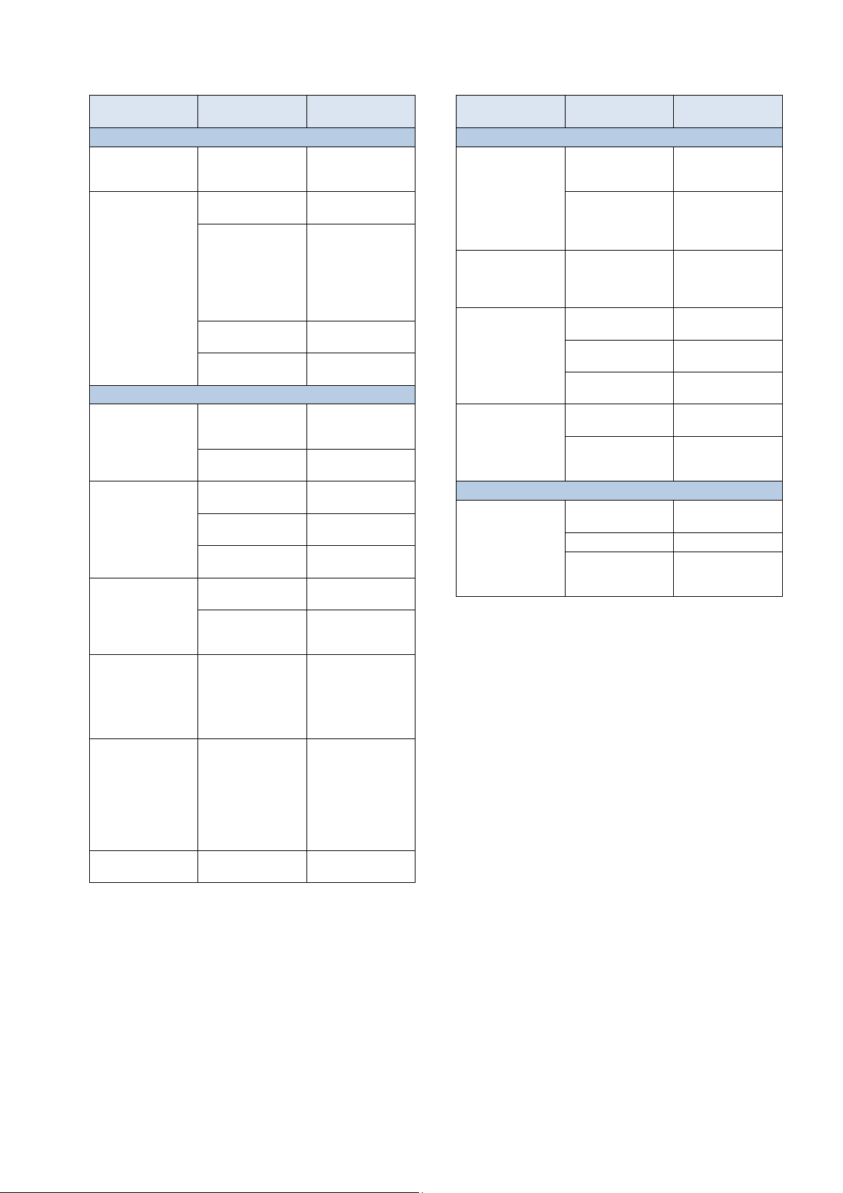
51
Dosing pump has sucked
Troubleshooting
Type of problem Potential cause of the
Redox measurement
Redox potential does not
coincide with the control
measurement
Calibration failure in
redox calibration
Redox (mV) control (chlorine or bromine dosing)
The unit shows a dosing
output of 0% although
there is a deviation
between actual value
and setpoint
The dosing pump
continues to run despite
the unit showing a
dosing output of 0%
Dosing pump is running,
but there is no redox
correction
Redox value fluctuating
around the setpoint
Redox potential deviates
from setpoint over a
longer period of time
Type of problem Potential cause of the
problem
Calibration erroneous or
was a long time ago
Erroneous entry of
calibration values
Electrode contaminated
or defective
Moisture in cable Dry or replace
Measurement amplifier
defective
Dosing is blocked by an
alarm (flow, level, or
dosing time alarm)
Start delay still running Wait for end of start
Fuse on the dosing
pump is burnt
Dosing relay defective Replace the respective
Dosing pump defective Replace the dosing
Container is empty Replace maintenance
Dosing pump has sucked
in air and is no longer
dosing
Redox control
dosing output is too high
Redox control
dosing output is too low
problem
Remediation of the
problem
Perform a new
calibration
Repeat calibration
Use 5-10% hydrochloric
acid to clean the
electrode and then rinse
with distilled water. If the
electrode does not
calibrate after this, then it
has to be replaced.
cable
Device has to be
repaired or replaced
Remediate alarm cause
Acknowledge alarm
delay
Replace fuse
(2AT)
relay
pump
product
Remove air from dosing
head
Set a higher value for the
p-range, which will lower
dosing output.
Reducing the minimum
switch-on time hinders
overdosage.
Set a lower value for the
p-range, which will
increase dosing output.
An increase in minimum
switch-on time will result
in the setpoint be
approached more
quickly.
Remediation of the
problem
Type of problem Potential cause of the
Automatic dosage O2 (BayroSoft)
The unit does not trigger
dosing at the expected
point in time
Dosing output is higher
than the programmed
dosing output
The dosing pump is not
running despite the unit
showing dosing output
The dosing pump is
running, but no
maintenance product is
reaching the water
Temperature measurement
Temperature display
erroneous
problem
Dosing is blocked by an
alarm (flow or level
alarm)
Date and time are not
correctly configured on
the measuring and
control unit
The actual dosing output
increases due to
temperature
compensation
Fuse on the dosing
pump is burnt
Dosing relay defective Replace the respective
Dosing pump defective Replace the dosing
Container is empty Replace maintenance
in air and is no longer
dosing
Temperature sensor
defective
Moisture in cable Dry or replace cable
Incorrect sensor type
configured
(PT1000 / KTY83)
Remediation of the
problem
Remediate alarm cause
Acknowledge alarm
Configure date and time
on the customer level
-
Replace fuse
(2AT)
relay
pump
product
Remove air from dosing
head
Replace temperature
sensor.
Correct setting in the
"temperature" menu (in
service menu only)
User Manual PoolManager® 92
Page 93
51
Dosing pump has sucked
Dosing pump has sucked
Chlorine value fluctuating
longer period of time
increase dosing output.
Troubleshooting
Chlorine measurement (PoolManager® PRO only)
Type of problem Potential cause of the
DPD measurement and
unit display show
different values
Calibration failure in pH
calibration
Chlorine measurement is
unstable
Chlorine control / chlorine dosing
The unit shows a dosing
output of 0% although
there is a deviation
between actual value
and setpoint
The dosing pump
continues to run despite
the unit showing a
dosing output of 0%
Dosing pump is running,
but there is no chlorine
correction
around the setpoint
Chlorine value deviates
from setpoint over a
problem
Calibration erroneous or
was a long time ago
Measurement water feed
to low or turned off
(cleaning balls not
rotating sufficiently)
Measurement water feed
not consistent
DPD chemicals replaced
or expired chemicals
used
Film (such as calcium)
on the gold electrode
Erroneous entry of
calibration values
Chlorine level in the
water too low during
calibration
Glass electrode or gold
electrode in the chlorine
measuring cell too old or
defective
Measurement amplifier
defective
Measurement water feed
too low or turned off
Dosing is blocked by an
alarm (flow, level, or
dosing alarm)
Start delay still running Wait for end of start
Fuse on the dosing
pump is burnt
Dosing relay defective Replace the respective
Dosing pump defective Replace the dosing
Container is empty Replace maintenance
in air and is no longer
dosing
in air and is no longer
dosing
Chlorine control dosing
output is too high
Chlorine control dosing
output is too low
Remediation of the
problem
Perform a new
calibration.
Check measurement
water feed, then perform
new calibration
Ensure consistent
measurement water
feed , then perform new
calibration
Use new DPD
chemicals, perform new
calibration
Cleanse the gold
electrode with a soft
towel and diluted
hydrochloric acid. After
cleaning, observe the
time it takes for the
measuring cell to
stablise.
Repeat calibration
Perform new calibration
with a chlorine level
close to the setpoint
Replace glass electrode
or
gold electrode
Device has to be
replaced
Secure measurement
water feed such that the
balls rotate evenly
again.
Remediate alarm cause
Acknowledge alarm
delay
Replace fuse
(2AT)
relay
pump
product
Remove air from dosing
head
Remove air from dosing
head
Set a higher value for the
p-range, which will lower
dosing output.
Reducing the minimum
switch-on time also
hinders overdosage.
Set a lower value for the
p-range, which will
An increase in minimum
switch-on time will result
in the setpoint being
approached more
quickly.
User Manual PoolManager® 93
Page 94
52
•
•
Potential free or 230V~ (max. 4A)
•
•
Technical data
52 Technical data
Measurement dimensions / ranges
pH 0 – 10 (temperature compensated)
• Redox 0 – 1,000 mV
• Free chlorine 0.01 – 10 ppm / mg/l
• Temperature 2x 0 – 50 °C, 1x 0 – 75 °C
Measurement amplifier tolerances
pH, chlorine, and redox: max. +/- 0.5% from measurement range terminal
value
Temperature: max. +/- 0.5 °C
Measuring inputs
pH and redox via BNC, chlorine and temperature via terminal
Control
Proportional control with interval portions (minimum dosing output)
Bi-directional control for pH, mono-directional control for redox and chlorine
Dosing outputs
3 relay switch outputs
• Potential free or 230V~ (max. 2A)
• Pulse widths or pulse frequency triggering
Alarm relay
Inputs / outputs for supplemental functions
4 universal switch inputs (potential free)
• 4 universal relay switch outputs,
potential free or 230V~ (max. 4A)
• Unused dosing outputs
Monitoring functions
Measurement water circuit flow
• Pressure switch (optional)
• Level pH
• Level disinfection
Expansions
3 plugs for add-on modules
Power outputs 0/4-20mA
Plug-in module PM5-SA4 CONVERTER 0/4-20MA (Art. no. 127011), four
outputs 0/4-20mA (optional).
1 or 2 modules can be plugged in.
Interfaces
LAN (RJ45) 100 Mbit/s (CAT5 cable minimum)
USB, CAN, SD card slot
Plug-in module PM5-RS485 CONVERTER (Art. no. 127012),
RS-485 data interface (optional)
Communication
Embedded web server and web-based graphical user interface
Electrical connection
100 – 240 V~, 50/60 Hz
Temperature ranges
Operating temperature 0 °C – 50 °C
Storage temperature -20 °C – 70 °C
Controller rating
IP 65
Dimensions
715 x 495 x 125 mm (WxHxL)
User Manual PoolManager® 94
Page 95

EC Declaration of Conformity
53 EC Declaration of Conformity
EC Declaration of Conformity
We,
, hereby declare that the models of the product named in the following that we bring into circulation meet the
requirements of the indicated EC directive.
This declaration will lose its validity in the event of uncoordinated modifications to the product.
Product designation:
Product model:
Bayrol Deutschland GmbH
Robert-Koch-Str. 4
82152 Planegg/Steinkirchen
Germany
Measurement, control, and dosing
system
PoolManager® / Analyt (5th generation, starting 2012)
PoolManager® Cl (Chlorine), PoolManager® Br (Bromine),
PoolManager® O2 (Oxygen), PoolManager® PRO, Analyt 2, Analyt 3
Series no.:
EC directives:
Harmonizing
standards used:
Date, manufacturer signature:
Signer's information:
See type plate
EC - Low Voltage Directive (2006/95/EC)
EC - EMC Directive (2004/108/EC)
EN61000-3-2
EN61000-3-3
EN61000-4-2
EN61000-4-3
EN61000-4-3
EN61000-4-4
EN61000-4-5
EN61000-4-6
EN61000-4-8
EN61000-4-11
01/05/2012,
 Loading...