


TKNSPD.BK Page i Thursday, July 17, 1997 11:43 AM
Using the 8-port
TokenSpeed and
TokenSpeed/MCP
Switch Modules
Part No. 893-01019-A
June 1997

TKNSPD.BK Page ii Thursday, July 17, 1997 11:43 AM
4401 Great America Parkway 8 Federal Street
Santa Clara, CA 95054 Billerica, MA 01821
© 1997 by Bay Networks, Inc. All rights reserved.
Trademarks
Bay Networks is a registered trademark of Bay Networks, Inc.
Bay Networks Press, Centillion 50, Centillion 100, SpeedV iew , and Tok enSpeed are trademarks of Bay Netw orks, Inc.
Other brand and product names are registered trademarks or trademarks of their respective holders.
Statement of Conditions
In the interest of improving internal design, operational function, and/or reliability, Bay Networks, Inc. reserves the
right to make changes to the products described in this document without notice.
Federal Communications Commission (FCC) Statement
Note: This equipment has been tested and found to comply with the limits for a Class A digital device, pursuant to
Part 15 of the FCC rules. These limits are designed to provide reasonable protection against harmful interference when
the equipment is operated in a commercial environment. This equipment generates, uses, and can radiate radio
frequency energy. If it is not installed and used in accordance with the instruction manual, it may cause harmful
interference to radio communications. Operation of this equipment in a residential area is likely to cause harmful
interference, in which case users will be required to take whatever measures may be necessary to correct the
interference at their own expense.
EN 55 022 Declaration of Conformance
This is to certify that the Bay Networks TokenSpeed module and TokenSpeed/MCP module are shielded against the
generation of radio interference in accordance with the application of Council Directive 89/336/EEC, Article 4a.
Conformity is declared by the application of EN 55 022 Class A (CISPR 22).
Compliance is dependent upon the use of shielded AC power cables.
Warning:
interference, in which case, the user may be required to take appropriate measures.
This is a Class A product. In a domestic environment, this product may cause radio
ii
893-01019-A

TKNSPD.BK Page iii Thursday, July 17, 1997 11:43 AM
Voluntary Control Council for Interference (VCCI) Statement
This equipment is in the first category (information equipment to be used in commercial and/or industrial areas) and
conforms to the standards set by the Voluntary Control Council for Interference by Data Processing Equipment and
Electronic Office Machines that are aimed at preventing radio interference in commercial and/or industrial areas.
Consequently, when this equipment is used in a residential area or in an adjacent area thereto, radio interference may
be caused to equipment such as radios and TV receivers.
Declaration of Conformity
These products conform to the provisions of Council Directive 89/336/EEC and 72/23/EEC. The Declaration of
Conformity is available on the Bay Networks World Wide Web site at www.baynetworks.com.
Bay Networks, Inc. Software License Agreement
NOTICE:
installing the hardware unit with pre-enabled software (each of which is referred to as “Software” in this Agreement).
BY COPYING OR USING THE SOFTWARE, Y OU A CCEPT ALL OF THE TERMS AND CONDITIONS OF THIS
LICENSE A GREEMENT. THE TERMS EXPRESSED IN THIS AGREEMENT ARE THE ONLY TERMS UNDER
WHICH BAY NETWORKS WILL PERMIT YOU TO USE THE SOFTWARE. If you do not accept these terms and
conditions, return the product, unused and in the original shipping container, within 30 days of purchase to obtain a
credit for the full purchase price.
1. License Grant.
nonexclusive, nontransferable license: (a) to use the Softw are either on a single computer or, if applicable, on a single
authorized device identified by host ID, for which it was originally acquired; (b) to copy the Software solely for
backup purposes in support of authorized use of the Software; and (c) to use and copy the associated user manual
solely in support of authorized use of the Software by Licensee. This license applies to the Software only and does not
extend to Bay Networks Agent software or other Bay Networks software products. Bay Networks Agent software or
other Bay Networks software products are licensed for use under the terms of the applicable Bay Networks, Inc.
Software License Agreement that accompanies such software and upon payment by the end user of the applicable
license fees for such software.
2. Restrictions on use; reservation of rights.
Networks and/or its licensors retain all title and ownership in both the Software and user manuals, including any
revisions made by Bay Networks or its licensors. The cop yright notice must be reproduced and included with any cop y
of any portion of the Software or user manuals. Licensee may not modify, translate, decompile, disassemble, use for
any competitive analysis, reverse engineer, distribute, or create derivati ve works from the Software or user manuals or
any copy, in whole or in part. Except as expressly provided in this Agreement, Licensee may not copy or transfer the
Software or user manuals, in whole or in part. The Software and user manuals embody Bay Networks’ and its
licensors’ confidential and proprietary intellectual property. Licensee shall not sublicense, assign, or otherwise
disclose to any third party the Software, or any information about the operation, design, performance, or
implementation of the Software and user manuals that is confidential to Bay Networks and its licensors; however,
Licensee may grant permission to its consultants, subcontractors, and agents to use the Software at Licensee’ s f acility,
provided they have agreed to use the Software only in accordance with the terms of this license.
Please carefully read this license agreement before copying or using the accompanying software or
Bay Networks, Inc. (“Bay Networks”) grants the end user of the Software (“Licensee”) a personal,
The Software and user manuals are protected under copyright laws. Bay
893-01019-A
iii

TKNSPD.BK Page iv Thursday, July 17, 1997 11:43 AM
3. Limited warranty.
Bay Networks warrants each item of Software, as delivered by Bay Networks and properly
installed and operated on Bay Networks hardware or other equipment it is originally licensed for, to function
substantially as described in its accompanying user manual during its warranty period, which begins on the date
Software is first shipped to Licensee. If any item of Software fails to so function during its warranty period, as the sole
remedy Bay Networks will at its discretion provide a suitable fix, patch, or workaround for the problem that may be
included in a future Software release. Bay Networks further warrants to Licensee that the media on which the Software
is provided will be free from defects in materials and workmanship under normal use for a period of 90 days from the
date Software is first shipped to Licensee. Bay Networks will replace defective media at no charge if it is returned to
Bay Networks during the warranty period along with proof of the date of shipment. This warranty does not apply if the
media has been damaged as a result of accident, misuse, or abuse. The Licensee assumes all responsibility for
selection of the Software to achieve Licensee’s intended results and for the installation, use, and results obtained from
the Software. Bay Networks does not warrant (a) that the functions contained in the software will meet the Licensee’s
requirements, (b) that the Software will operate in the hardware or software combinations that the Licensee may select,
(c) that the operation of the Software will be uninterrupted or error free, or (d) that all defects in the operation of the
Software will be corrected. Bay Networks is not obligated to remedy any Software defect that cannot be reproduced
with the latest Software release. These warranties do not apply to the Software if it has been (i) altered, except by Bay
Networks or in accordance with its instructions; (ii) used in conjunction with another vendor’ s product, resulting in the
defect; or (iii) damaged by improper environment, abuse, misuse, accident, or negligence. THE FOREGOING
WARRANTIES AND LIMITATIONS ARE EXCLUSIVE REMEDIES AND ARE IN LIEU OF ALL OTHER
WARRANTIES EXPRESS OR IMPLIED, INCLUDING WITHOUT LIMITATION ANY WARRANTY OF
MERCHANTABILITY OR FITNESS FOR A PARTICULAR PURPOSE. Licensee is responsible for the security of
its own data and information and for maintaining adequate procedures apart from the Software to reconstruct lost or
altered files, data, or programs.
4. Limitation of liability.
IN NO EVENT WILL BAY NETWORKS OR ITS LICENSORS BE LIABLE FOR ANY
COST OF SUBSTITUTE PROCUREMENT; SPECIAL, INDIRECT, INCIDENTAL, OR CONSEQUENTIAL
DAMAGES; OR ANY DAMAGES RESULTING FROM INACCURATE OR LOST DATA OR LOSS OF USE OR
PROFITS ARISING OUT OF OR IN CONNECTION WITH THE PERFORMANCE OF THE SOFTWARE, EVEN
IF BAY NETWORKS HAS BEEN ADVISED OF THE POSSIBILITY OF SUCH DAMAGES. IN NO EVENT
SHALL THE LIABILITY OF BAY NETWORKS RELATING TO THE SOFTWARE OR THIS AGREEMENT
EXCEED THE PRICE PAID TO BAY NETWORKS FOR THE SOFTWARE LICENSE.
5. Government Licensees.
This provision applies to all Software and documentation acquired directly or indirectly by
or on behalf of the United States Government. The Software and documentation are commercial products, licensed on
the open market at market prices, and were developed entirely at private expense and without the use of any U.S.
Government funds. The license to the U.S. Government is granted only with restricted rights, and use, duplication, or
disclosure by the U.S. Government is subject to the restrictions set forth in subparagraph (c)(1) of the Commercial
Computer Software––Restricted Rights clause of FAR 52.227-19 and the limitations set out in this license for civilian
agencies, and subparagraph (c)(1)(ii) of the Rights in Technical Data and Computer Software clause of DFARS
252.227-7013, for agencies of the Department of Defense or their successors, whichever is applicable.
6. Use of Software in the European Community.
This provision applies to all Software acquired for use within the
European Community. If Licensee uses the Software within a country in the European Community, the Software
Directive enacted by the Council of European Communities Directive dated 14 May, 1991, will apply to the
examination of the Software to facilitate interoperability . Licensee agrees to notify Bay Netw orks of any such intended
examination of the Software and may procure support and assistance from Bay Networks.
7. Term and termination.
This license is effectiv e until terminated; howe v er , all of the restrictions with respect to Bay
Networks’ copyright in the Software and user manuals will cease being effective at the date of expiration of the Bay
Networks copyright; those restrictions relating to use and disclosure of Bay Networks’ confidential information shall
continue in effect. Licensee may terminate this license at any time. The license will automatically terminate if
Licensee fails to comply with any of the terms and conditions of the license. Upon termination for any reason,
Licensee will immediately destroy or return to Bay Networks the Software, user manuals, and all copies.
Bay Networks is not liable to Licensee for damages in any form solely by reason of the termination of this license.
iv
893-01019-A

TKNSPD.BK Page v Thursday, July 17, 1997 11:43 AM
8. Export and Re-export.
Licensee agrees not to export, directly or indirectly, the Software or related technical data
or information without first obtaining any required export licenses or other governmental approvals. Without limiting
the foregoing, Licensee, on behalf of itself and its subsidiaries and affiliates, agrees that it will not, without first
obtaining all export licenses and approvals required by the U.S. Government: (i) export, re-export, transfer, or divert
any such Software or technical data, or any direct product thereof, to any country to which such exports or re-exports
are restricted or embargoed under United States export control laws and regulations, or to any national or resident of
such restricted or embargoed countries; or (ii) provide the Software or related technical data or information to any
military end user or for any military end use, including the design, development, or production of any chemical,
nuclear, or biological weapons.
9. General.
If any provision of this Agreement is held to be invalid or unenforceable by a court of competent
jurisdiction, the remainder of the provisions of this Agreement shall remain in full force and effect. This Agreement
will be governed by the laws of the state of California.
Should you have any questions concerning this Agreement, contact Bay Networks, Inc., 4401 Great America P arkway,
P.O. Box 58185, Santa Clara, California 95052-8185.
LICENSEE ACKNOWLEDGES THAT LICENSEE HAS READ THIS AGREEMENT, UNDERSTANDS IT, AND
AGREES TO BE BOUND BY ITS TERMS AND CONDITIONS. LICENSEE FURTHER AGREES THAT THIS
AGREEMENT IS THE ENTIRE AND EXCLUSIVE AGREEMENT BETWEEN BAY NETWORKS AND
LICENSEE, WHICH SUPERSEDES ALL PRIOR ORAL AND WRITTEN AGREEMENTS AND
COMMUNICATIONS BETWEEN THE PARTIES PERTAINING TO THE SUBJECT MATTER OF THIS
AGREEMENT. NO DIFFERENT OR ADDITIONAL TERMS WILL BE ENFORCEABLE AGAINST
BAY NETWORKS UNLESS BAY NETWORKS GIVES ITS EXPRESS WRITTEN CONSENT, INCLUDING
AN EXPRESS WAIVER OF THE TERMS OF THIS AGREEMENT.
893-01019-A
v

TKNSPD.BK Page vi Thursday, July 17, 1997 11:43 AM
vi
893-01019-A

TKNSPD.BK Page vii Thursday, July 17, 1997 11:43 AM
Preface
Purpose ...........................................................................................................................xiii
Audience ..........................................................................................................................xiii
Conventions .....................................................................................................................xiv
Special Message Formats .........................................................................................xiv
Two-tiered Procedure Format ....................................................................................xiv
Related Publications ........................................................................................................ xv
Ordering Bay Networks Publications ...............................................................................xv
Bay Networks Customer Support ....................................................................................xvi
How to Get Help ..............................................................................................................xvi
For More Information ......................................................................................................xvii
Contents
Chapter 1
Overview of the TokenSpeed Module
About the TokenSpeed Module .......................................................................................1-1
Features .........................................................................................................................1-2
TokenSpeed Module Ports and Connectivity ...........................................................1-2
Filtering ....................................................................................................................1-3
Caching and Proxy ...................................................................................................1-3
Fault Tolerance .........................................................................................................1-3
Network Management ..............................................................................................1-3
Physical Description .......................................................................................................1-4
Chapter 2
TokenSpeed Module Applications
Giving a Server a Dedicated Port ...................................................................................2-1
Segmenting a Ring .........................................................................................................2-2
Connecting a Segment Through the RI or RO Port ..................................................2-3
Connecting a Segment Using a Lobe Port ...............................................................2-4
Replacing a Source Route Bridge or Router ..................................................................2-5
Concentrating Rings into a Router .................................................................................2-5
893-01019-A
vii

TKNSPD.BK Page viii Thursday, July 17, 1997 11:43 AM
Chapter 3
Installing and Connecting the TokenSpeed Module
Preparing for Installation .................................................................................................3-1
Installing the TokenSpeed Module ..................................................................................3-2
Connecting Cables to TokenSpeed Ports .......................................................................3-5
Token Ring Connections ..........................................................................................3-6
Verifying the Installation ..................................................................................................3-7
TokenSpeed Module LEDs .......................................................................................3-8
LED Switch Startup Sequence .................................................................................3-8
Configuring the TokenSpeed Module ..............................................................................3-9
Removing and Replacing a Module ..............................................................................3-11
Replacing a TokenSpeed/MCP Module ..................................................................3-12
Replacing a TokenSpeed Module ...........................................................................3-14
Chapter 4
Troubleshooting the TokenSpeed Module
Switch Startup Failure with TokenSpeed/MCP ...............................................................4-2
TokenSpeed Module Startup Failure ..............................................................................4-3
Port Insertion Problems ..................................................................................................4-4
Appendix A
Technical Specifications
Appendix B
Cables
Port Types ...................................................................................................................... B-2
Cable Types ................................................................................................................... B-2
Token Ring Connectors on the TokenSpeed Module ..................................................... B-3
Cable and Connector Pin Assignments ......................................................................... B-4
RJ-45 to RJ-45 Connection ..................................................................................... B-5
RJ-45 to DB-9 Connection ...................................................................................... B-8
RJ-45 to IBM Type 1 Connection ........................................................................... B-11
Serial MCP Connections ............................................................................................. B-13
Index
viii
893-01019-A

TKNSPD.BK Page ix Thursday, July 17, 1997 11:43 AM
Figure 1-1. Hardware features of the TokenSpeed module ........................................1-4
Figure 2-1. Giving a server a dedicated port ..............................................................2-2
Figure 2-2. Connecting a ring segment through an RI/RO port (ring segment 2) ......2-3
Figure 2-3. Connecting ring segments through lobe ports .........................................2-4
Figure 2-4. Replacing a source route bridge or router ...............................................2-5
Figure 2-5. Concentrating multiple rings into a router ................................................2-6
Figure 3-1. Removing a filler panel ............................................................................3-3
Figure 3-2. Inserter/extractor levers ready for installation ..........................................3-3
Figure 3-3. Slot module guides ..................................................................................3-4
Figure 3-4. Inserting the module into the chassis ......................................................3-4
Figure 3-5. Seating the module ..................................................................................3-5
Figure 3-6. Connecting a cable to an RJ-45 port on the TokenSpeed module ...........3-6
Figure 3-7. Connecting the serial MCP cable to the TokenSpeed/MCP .....................3-7
Figure 3-8. TokenSpeed module LEDs ......................................................................3-8
Figure 3-9. Loosening the TokenSpeed module .......................................................3-12
Figure 3-10. Removing the module from the switch chassis ......................................3-13
Figure 3-11. Loosening the TokenSpeed module .......................................................3-14
Figure 3-12. Removing the module from the Centillion chassis .................................3-15
Figure B-1. RJ-45 connector on the TokenSpeed module ......................................... B-3
Figure B-2. Connectors for token ring network cables ............................................... B-4
Figure B-3. Hub to station connection (RJ-45 to RJ-45) ............................................ B-5
Figure B-4. Station to hub connection (RJ-45 to RJ-45) ............................................ B-6
Figure B-5. Bay/SNPX RO to RI connection (RJ-45 to RJ-45) .................................. B-6
Figure B-6. RI–other to RO connection (RJ-45 to RJ-45) .......................................... B-7
Figure B-7. RO–other to RI connection (RJ-45 to RJ-45) .......................................... B-7
Figure B-8. Hub to station connection (RJ-45 to DB-9) ............................................. B-8
Figure B-9. Station to hub connection (RJ-45 to DB-9) ............................................. B-9
Figure B-10. Bay/SNPX RO to RI connection (RJ-45 to DB-9) ................................... B-9
Figures
893-01019-A
ix

TKNSPD.BK Page x Thursday, July 17, 1997 11:43 AM
Figure B-11. RI–other to RO connection (RJ-45 to DB-9) ......................................... B-10
Figure B-12. RO–other to RI connection (RJ-45 to DB-9) ......................................... B-10
Figure B-13. Station to hub connection (RJ-45 to IBM Type 1) .................................. B-11
Figure B-14. Bay/SNPX RO to RI connection (RJ-45 to IBM Type 1) ........................ B-12
Figure B-15. RI–other to RO connection (RJ-45 to IBM Type 1) ................................ B-12
Figure B-16. RO–other to RI connection (RJ-45 to IBM Type 1) ................................ B-13
x
893-01019-A

TKNSPD.BK Page xi Thursday, July 17, 1997 11:43 AM
Table 1. Related publications .................................................................................. xv
Table 3-1. Port types for the TokenSpeed module ....................................................3-6
Table 3-2. TokenSpeed module LEDs ......................................................................3-8
Table 3-3. Factory default configuration settings ......................................................3-9
Table B-1. Port types for the TokenSpeed module ................................................... B-2
Table B-2. Cable distances ...................................................................................... B-3
Table B-3. Male Mini DIN 8 to male DB-25 cable ................................................... B-13
Table B-4. Female DB-25 to female DB-9 adapter ................................................. B-14
Tables
893-01019-A
xi

TKNSPD.BK Page xii Thursday, July 17, 1997 11:43 AM
xii
893-01019-A

TKNSPD.BK Page xiii Thursday, July 17, 1997 11:43 AM
Congratulations on your purchase of the Bay Networks® 8-port TokenSpeed™
or TokenSpeed/MCP switch module. The TokenSpeed and TokenSpeed/MCP
switch modules provide token ring connectivity for the Centillion 100™ and
Centillion 50™ switches. In addition, a TokenSpeed/MCP module can provide
the master control processing functions for a Centillion™ switch.
Preface
Purpose
Audience
In this guide, the TokenSpeed module and TokenSpeed/MCP module are referred
to collectively as the TokenSpeed module. Each model is referred to specifically
when features and functions are unique to that particular model.
This guide provides information about installing and using the TokenSpeed
module. Configuration of the TokenSpeed module is covered in
SpeedView 2.1 for Windows
Related Publications” on page xv.
“
This guide is intended for local area network administrators with the following
background:
• Familiarity with token ring network administration
• SpeedView for Windows: working knowledge of Windows
. For more information about these guides, see
Using
• SpeedView for UNIX: working knowledge of UNIX
893-01019-A
xiii

TKNSPD.BK Page xiv Thursday, July 17, 1997 11:43 AM
Using the 8-port TokenSpeed and TokenSpeed/MCP Switch Modules
Conventions
This section describes the conventions used in this guide.
Special Message Formats
This guide uses the following formats to highlight special messages:
Note:
This format is used to highlight information of importance or special
interest.
Caution:
This format is used to highlight information that will help you
prevent equipment failure or loss of data.
Warning:
This format is used to highlight material involving possibility of
injury or equipment damage.
Two-tiered Procedure Format
The procedural steps in this guide are presented in a two-tiered format. The first
tier describes the step briefly but precisely. An experienced user may need to read
only the first tier to complete the task. The second tier describes the step in more
detail and may include results of performing the step.
xiv
893-01019-A

TKNSPD.BK Page xv Thursday, July 17, 1997 11:43 AM
Related Publications
For more information about using the TokenSpeed module, refer to the
publications listed in T
Table 1. Related publications
Title Description
Preface
able 1.
Installation and Reference for the Centillion
Chassis
(Bay Networks part number 893-894-A)
Using SpeedView 2.1 for Windows
(Bay Networks part number 893-891-B)
Reference Guide for the Centillion 100 and
Model 5000BH Switches
(Bay Networks part number 893-01006-A)
Reference Guide for the Centillion
Command Line Interface
(Bay Networks part number 893-00985-A)
Using the Centillion 50 Token Ring
Workgroup Switch
number 893-01015-A)
(Bay Networks part
Ordering Bay Networks Publications
To purchase additional copies of this document or other Bay Networks
publications, order by part number from Bay Networks Press™ at the following
numbers:
Describes installation procedures for the
Centillion chassis.
Describes the software configuration
features for the Centillion switch and
modules from a Windows platform.
Provides reference information about
switching terminology and concepts;
describes configuration examples using
Centillion 100 and Model 5000BH switches.
Describes setup and configuration
procedures for Centillion switches using the
command line interface.
Describes typical network uses and
installation procedures for the Centillion 50T
switch.
• Phone—U.S./Canada: 1-888-422-9773
• Phone—International: 1-510-490-4752
• Fax—U.S./Canada and International: 1-510-498-2609
893-01019-A
xv

TKNSPD.BK Page xvi Thursday, July 17, 1997 11:43 AM
Using the 8-port TokenSpeed and TokenSpeed/MCP Switch Modules
Bay Networks Customer Support
You can purchase a support contract from your Bay Networks distributor or
authorized reseller, or directly from Bay Networks Services. For information
about, or to purchase a Bay Networks service contract, either call your local
Bay Networks field sales office or one of the following numbers:
Region Telephone number Fax number
United States and
Canada
Europe 33-4-92-96-69-66 33-4-92-96-69-96
Asia/Pacific 61-2-9927-8888 61-2-9927-8899
Latin America 561-988-7661 561-988-7550
1-800-2LANWAN; then enter Express
Routing Code (ERC) 290, when prompted,
to purchase or renew a service contract
1-508-916-8880 (direct)
How to Get Help
1-508-670-8766
If you purchased a service contract for your Bay Networks product from a
distributor or authorized reseller, contact the technical support staff for that
distributor or reseller for assistance.
If you purchased a Bay Networks service program, call one of the following
Bay Networks Technical Solutions Centers:
Technical Solutions Center Telephone number Fax number
Billerica, MA 1-800-2LANWAN 508-670-8765
Santa Clara, CA 1-800-2LANWAN 408-495-1188
Valbonne, France 33-4-92-96-69-68 33-4-92-96-69-98
Sydney, Australia 61-2-9927-8800 61-2-9927-8811
Tokyo, Japan 81-3-5402-0180 81-3-5402-0173
Use Express Routing Code 145 to reach a support representative for token ring
switching products.
xvi
893-01019-A

TKNSPD.BK Page xvii Thursday, July 17, 1997 11:43 AM
For More Information
For information about Bay Networks and its products, visit the Bay Networks
World Wide Web (WWW) site at http://www.baynetworks.com. To learn more
about Bay Networks Customer Service, select Customer Service on the opening
Web page.
Preface
893-01019-A
xvii

TKNSPD.BK Page xviii Thursday, July 17, 1997 11:43 AM
Using the 8-port TokenSpeed and TokenSpeed/MCP Switch Modules
xviii
893-01019-A

TKNSPD.BK Page 1 Thursday, July 17, 1997 11:43 AM
Overview of the TokenSpeed Module
This chapter introduces the 8-port TokenSpeed module and covers the following
topics:
• A summary of module functions, capabilities, and features (starting on this
page)
Chapter 1
• A physical description of the module printed circuit board and the board in
relation to the Centillion switch chassis (see page
About the TokenSpeed Module
The 8-port TokenSpeed module inserts into one slot of a Centillion 100 or
Centillion 50 switch chassis to provide token ring ports and, optionally, an
integrated master control processor (MCP). This module replaces earlier module
versions that provided only four ports. The TokenSpeed module comes in the
following configurations:
• A TokenSpeed module with eight switched token ring ports with RJ-45
connectors for unshielded twisted pair (UTP) or shielded twisted pair (STP)
cable
• A TokenSpeed/MCP module with eight switched token ring ports with RJ-45
connectors for UTP/STP cable and a serial port implemented on a Mini DIN 8
connector
These modules offer identical functional features for token ring connectivity.
In addition to providing token ring connectivity, a Tok enSpeed/MCP module also
manages the Centillion switch. The MCP port can be used to connect a network
management station. One (and only one) MCP module is required for each
Centillion chassis; however, an ATMSpeed/MCP or EtherSpeed/MCP module
can also be used to meet this requirement.
1-4)
893-01019-A
1-1

TKNSPD.BK Page 2 Thursday, July 17, 1997 11:43 AM
Using the 8-port TokenSpeed and TokenSpeed/MCP Switch Modules
Features
This section provides a summary of the features of the TokenSpeed module,
including the following topics:
• TokenSpeed module ports and connectivity
• Filtering
• Caching and proxy
• Fault tolerance
• Network management
TokenSpeed Module Ports and Connectivity
TokenSpeed module ports have the following features:
• Operation at 4 or 16 megabits per second (Mb/s), with automatic sensing of
the data rate of an inserting station
• Onboard connectors
— RJ-45 connector for UTP/STP connection to each token ring port
— One serial port with a Mini DIN 8 connector on the TokenSpeed/MCP
module
• Transparent, source route, and source route transparent bridging with
IEEE 802.1d or IBM Spanning Tree support
• Virtual ring partitioning for any combination of ports in a single switch, each
virtual ring appearing as a single ring in a source-routing network
• Per-port features
— LEDs to indicate operational status of each port
— Automatic adaptation to speed of inserting station: 4 or 16 Mb/s
— Automatic port deactivation for errors or administrative control
— Wire-speed port-to-port switching for local traffic without using any A TM
backplane bandwidth
1-2
893-01019-A

TKNSPD.BK Page 3 Thursday, July 17, 1997 11:43 AM
Filtering
The TokenSpeed module has the following filtering features:
• Support for NetBIOS name filters, datagram broadcast filters, and a name
query interval
• Filtering for any pattern up to 12 bytes wide in the first 255 bytes of a frame
• Per-port filter configuration
Caching and Proxy
The TokenSpeed module has the following caching and proxy features:
• Caching for NetBIOS names to reduce NetBIOS name broadcast packets
(Each switch can cache up to 500 NetBIOS names.)
Overview of the TokenSpeed Module
• Caching for Route Information Field (RIF) to speed up the explorer process
and reduce broadcasts (Each switch can cache up to 500 unique RIFs.)
• Cache capacity of up to 128 RIFs for source route explorer proxy and
5120 media access control (MAC) addresses
• Cache capacity of up to 10,240 MAC addresses in the MCP station table
Fault Tolerance
The TokenSpeed module has the following fault-tolerance features:
• Ability to install, remove, and replace a module in an operational chassis
(hot-swap)
• Flash memory download with storage for two configurations on the
TokenSpeed/MCP module
• Software update and management access over the network or a serial
connection to the TokenSpeed/MCP module
Network Management
The TokenSpeed/MCP module provides the following network management
features for the TokenSpeed module and other modules in a Centillion switch:
• Simple Network Management Protocol (SNMP) agent with Centillion
Management Information Base (MIB) extensions
893-01019-A
1-3
TKNSPD.BK Page 4 Thursday, July 17, 1997 11:43 AM
Using the 8-port TokenSpeed and TokenSpeed/MCP Switch Modules
• Bootstrap Protocol (BootP) and Trivial File Transfer Protocol (TFTP) support
• SpeedView
™
available for Windows environments over RS-232 and SNMP
For additional information about SpeedView, refer to
Windows
.
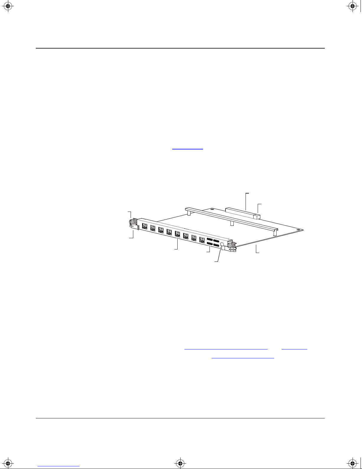
Physical Description
The TokenSpeed module (see Figure
circuit board with a metal module faceplate. The module has inserter/extractor
levers and captive retaining screws on each side of the front panel. The module
occupies a single slot in the Centillion switch chassis.
Captive retaining
screws
Inserter/extractor
levers
application for configuration management and monitoring,
Using SpeedView 2.1 for
1-1) is an assembly that consists of a printed
Backplane connector
Power supply
connector
8 ports (RJ-45)
MCP serial port (optional)
LEDs
Printed circuit
board
980FA
Figure 1-1. Hardware features of the TokenSpeed module
The module front panel contains eight RJ-45 connectors for the token ring ports
and an array of port LEDs that indicate ring insertion and port activity. The
TokenSpeed/MCP module also has a Mini DIN 8 connector for the serial MCP
port.
For descriptions of the LEDs, see “
For cable and connector specifications, see Appendix
TokenSpeed Module LEDs” on page 3-8.
B, “Cables.”
1-4
893-01019-A

TKNSPD.BK Page 1 Thursday, July 17, 1997 11:43 AM
This chapter provides information about typical uses of the TokenSpeed module
to improve network performance. The chapter includes information about the
following uses:
Chapter 2
TokenSpeed Module Applications
• Giving a server a dedicated port (see this page)
• Segmenting a ring (see page
• Replacing a source route bridge or router (see page
• Concentrating rings into a router (see page
2-2)
Giving a Server a Dedicated Port
You can improve server response and increase throughput capacity by giving a
server a dedicated port on the TokenSpeed module.
Note: Giving a server a dedicated port on the TokenSpeed module need not
increase the source route hop count. You can maintain or even decrease the
source route hop count by assigning the server to the same virtual ring as its
communicating stations (refer to Using SpeedView 2.1 for Windows.)
2-5)
2-5)
893-01019-A
2-1
TKNSPD.BK Page 2 Thursday, July 17, 1997 11:43 AM
Using the 8-port TokenSpeed and TokenSpeed/MCP Switch Modules
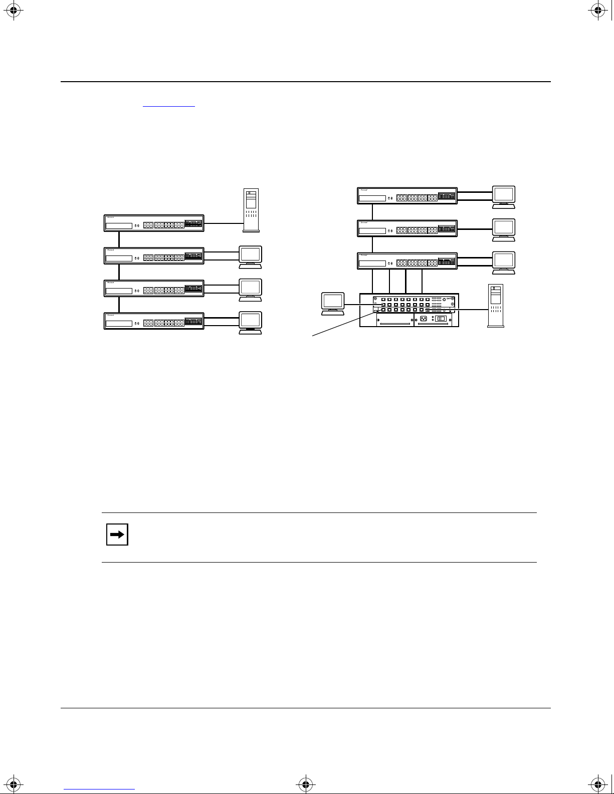
Figure 2-1 shows a network with a server connected to the network, first through
a shared-media hub and then through a TokenSpeed module in a Centillion 50
Token Ring Workgroup Switch.
BayStack 500-series
token ring hubs
Server
BayStack 500-series
token ring hubs
Users
Users
Before After
Figure 2-1. Giving a server a dedicated port
Segmenting a Ring
You can segment rings and connect the ring segments to the TokenSpeed module
using either Ring In/Ring Out (RI/RO) ports or lobe ports on the token ring hubs.
Note: If you connect a token ring hub to a switch using only the RI or RO
port, you have no backup path between the switch and the hub.
TokenSpeed
module
Centillion 50
token ring switch
7570EA
2-2 893-01019-A
TKNSPD.BK Page 3 Thursday, July 17, 1997 11:43 AM
Connecting a Segment Through the RI or RO Port
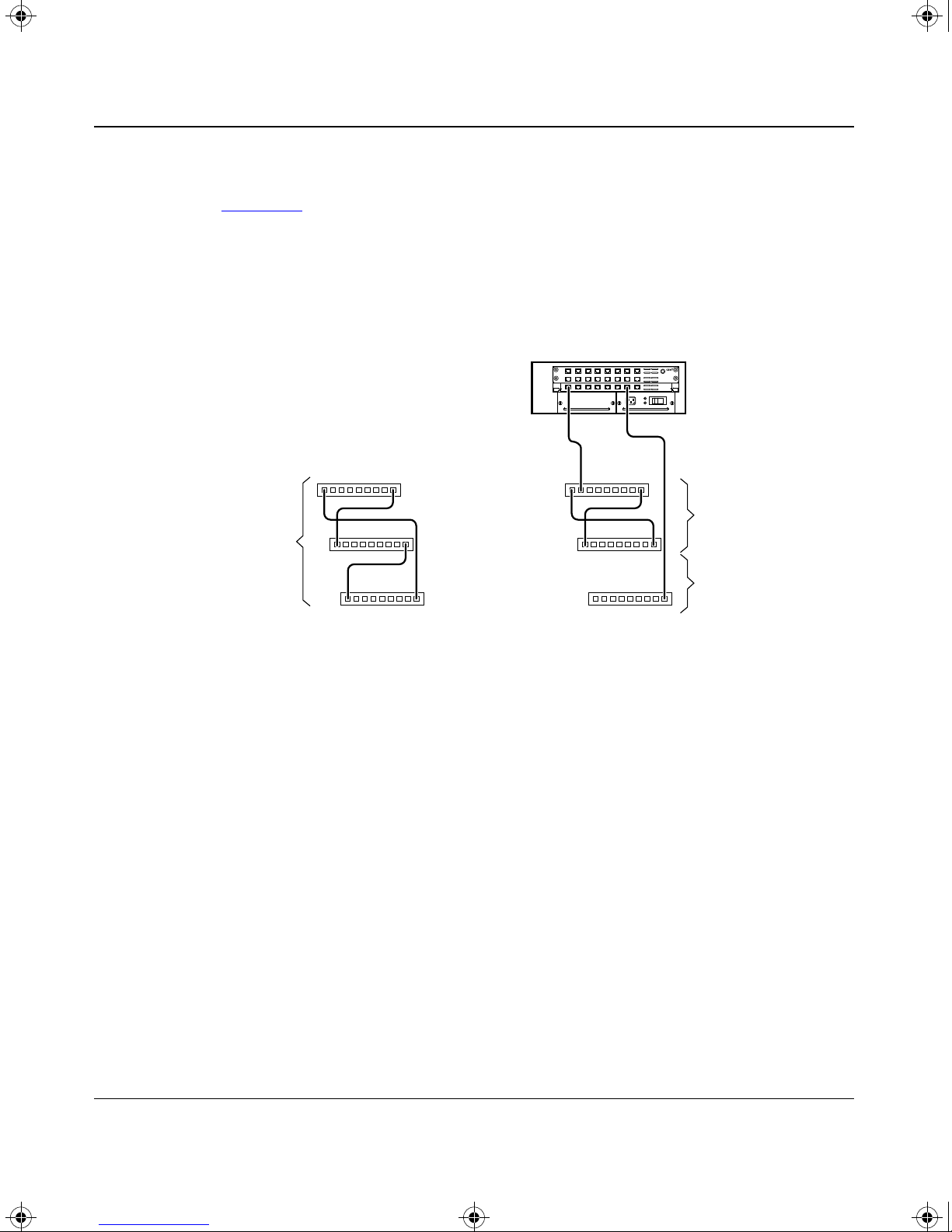
Figure 2-2 shows a network with IBM 8228-style media attachment units (MA Us)
forming a single ring segment. You can create two ring segments by connecting
one MAU to a TokenSpeed module through the RI or RO port on the MAU.
The remaining MAUs form a segment that is connected to the TokenSpeed
module through a lobe port on the MAU.
TokenSpeed Module Applications
Centillion 50 switch
RI
Single ring
segment
RO
Before After
RI RO
Ring segment 1
Ring segment 2
RO
Figure 2-2. Connecting a ring segment through an RI/RO port
(ring segment 2)
7567EA
893-01019-A 2-3

TKNSPD.BK Page 4 Thursday, July 17, 1997 11:43 AM
Using the 8-port TokenSpeed and TokenSpeed/MCP Switch Modules
Connecting a Segment Using a Lobe Port
Figure 2-3 shows a network with three stacked token ring hubs forming a single
ring segment. Each hub can be connected through a lobe port to a TokenSpeed
module to create three ring segments.
BayStack
token ring hub
Centillion 50
token ring switch
Single ring
segment
Model 2715
token ring hubs
Before
After
Figure 2-3. Connecting ring segments through lobe ports
Ring segment 1
Ring segment 2
Ring segment 3
7569EA
2-4 893-01019-A

TKNSPD.BK Page 5 Thursday, July 17, 1997 11:43 AM
Replacing a Source Route Bridge or Router
Figure 2-4 shows a network in which a Centillion switch replaces three source
route bridges.
Backbone ring
TokenSpeed Module Applications
RI RO
BridgeBridge Bridge
RI RO
User
rings
Before
Figure 2-4. Replacing a source route bridge or router
Concentrating Rings into a Router
Backbone hub 1 Backbone hub 2
Centillion 100
token ring
switch
User
rings
After
7568EA
To concentrate rings into a router , make sure virtual rings in the network are set up
in one of the following two ways:
• To segment a congested ring without using new router ports, be sure that all
stations previously connected to a single router port are in the same virtual
ring (refer to Using SpeedView 2.1 for Windows). The router will continue
to view the network the same way it did before the rings were segmented.
• To concentrate multiple, small ring segments into a router subnet and to free
router ports, be sure all segments are in the same virtual ring so that you can
group the entire virtual ring into a single router port. Be sure that the number
of devices in the virtual ring does not exceed the subnet size defined on the
router.
893-01019-A 2-5

TKNSPD.BK Page 6 Thursday, July 17, 1997 11:43 AM
Using the 8-port TokenSpeed and TokenSpeed/MCP Switch Modules
Figure 2-5 shows a network where each ring segment uses a separate router port.
By using a TokenSpeed module in a Centillion switch, you can concentrate many
physical ring segments into a few logical rings that use fewer router ports.
User rings
Ring 20
User rings
Ring segment 20
Ring segment 2
Ring segment 1
Router
Before: 20 router ports; 20 logical rings
Server
Figure 2-5. Concentrating multiple rings into a router
Ring 3
Ring 2
Ring 1
Centillion 50
token ring
switch
Ring 1
Ring 2
Router Server
After: 2 router ports; 2 logical rings
= Virtual ring
7571EA
2-6 893-01019-A

TKNSPD.BK Page 1 Thursday, July 17, 1997 11:43 AM
Installing and Connecting the TokenSpeed Module
This chapter explains how to install and connect a TokenSpeed module and
includes the following information and procedures:
• Preparing for installation (see this page)
Chapter 3
• Installing the TokenSpeed module (see page
• Connecting cables to TokenSpeed module ports (see page
• Verifying the installation (see page
• Configuring the TokenSpeed module (see page
• Removing and replacing a module (see page
Preparing for Installation
Before you install the TokenSpeed module, make sure that the Centillion switch
chassis is assembled and ready to accept modules. For more information, refer to
the installation instructions that were shipped with your switch chassis.
You need the following tools and materials to install the module:
• Medium flat-tip screwdriver for the captive retaining screws
• Grounded antistatic mat and wrist strap
3-2)
3-5)
3-7)
3-9)
3-11)
893-01019-A 3-1

TKNSPD.BK Page 2 Thursday, July 17, 1997 11:43 AM
Using the 8-port TokenSpeed and TokenSpeed/MCP Switch Modules
Caution: Centillion modules use electronic components that are sensitive to
static electricity. Static discharge from your clothing or other items around
you, even at levels that do not create a spark, can cause damage. Take all
possible precautions to prevent static discharge damage when working with
printed circuit boards.
Keep each board in its protective conductive bag until you are ready to install
it. If possible, place all printed circuit boards on an antistatic mat and wear a
grounded antistatic wrist strap and leash to free yourself of static.
If you lack a grounded antistatic wrist strap and mat, be careful to stand in one
place where you work (so you do not generate static electricity by friction) and
to free yourself of static by touching the metal of a grounded chassis before
handling a printed circuit board.
Installing the TokenSpeed Module
You can insert or remove a TokenSpeed module from a switch chassis while the
power is on without interrupting service in the other installed modules. This
ability is referred to as “hot swapping.”
Note: A TokenSpeed module can be hot inserted into a switch chassis at any
time. However, before removing an active module from a switch chassis, you
must deactivate the module by either unplugging all port cables or disablin g all
ports on the module. For additional information, see “
Replacing a Module” on page 3-11.
To install and secure the module in the chassis, follow these steps:
1. Remove the filler panel.
a. Loosen the two captive retaining screws on a filler panel until they
pop free of the chassis frame.
Removing and
3-2 893-01019-A

TKNSPD.BK Page 3 Thursday, July 17, 1997 11:43 AM
Rotate the left and right inserter/extractor levers away from the
b.
center of the filler panel to release the filler panel from the chassis
frame, and lift the filler panel away from the switch (see Figur
Installing and Connecting the TokenSpeed Module
e 3-1).
6463
Figure 3-1. Removing a filler panel
Make sure the module inserter/extractor levers are extending forward
2.
(see Figur
e 3-2).
Figure 3-2. Inserter/extractor levers ready for installation
6464
893-01019-A 3-3

TKNSPD.BK Page 4 Thursday, July 17, 1997 11:43 AM
Using the 8-port TokenSpeed and TokenSpeed/MCP Switch Modules
3. Align the left and right edges of the module in the guides on each side of
the slot (see Figur
e 3-3).
Figure 3-3. Slot module guides
Slide the module into the chassis until you feel it touch the backplane
4.
(see Figur
e 3-4).
The inserter/extractor levers should still be extended forward and in contact
with the front of the chassis. Do not push the module all the way into the
chassis.
6465
Figure 3-4. Inserting the module into the chassis
3-4 893-01019-A
6466

TKNSPD.BK Page 5 Thursday, July 17, 1997 11:43 AM
To seat the module against the backplane, rotate the inserter/extractor
5.
levers inward toward each other (see Figur
Installing and Connecting the TokenSpeed Module
e 3-5).
Figure 3-5. Seating the module
When the front panel of the module is flush with the front of the chassis, the
module backplane connectors are properly seated.
6. Align and tighten the captive retaining screw at each end of the module
front panel (see Figur
e 3-5).
Connecting Cables to TokenSpeed Ports
This section describes how to connect cables to the ports on a TokenSpeed
module with the following connections:
• Token ring connections to the RJ-45 ports
• Management connection to the MCP port
6537
893-01019-A 3-5

TKNSPD.BK Page 6 Thursday, July 17, 1997 11:43 AM
Using the 8-port TokenSpeed and TokenSpeed/MCP Switch Modules
Token Ring Connections
When you connect a network device to a token ring port on the TokenSpeed
module, you must specify a TokenSpeed port type using SpeedView. The port
type setting is based on the type of network connection you are connecting to the
TokenSpeed module. T
correct port type for each.
Table 3-1. Port types for the TokenSpeed module
Network device port TokenSpeed port type
Lobe port on token ring hub Station
Lobe port on IBM 8228 MAU or similar device Station
able 3-1 shows the types of network connections and the
Station port on a network interface card (NIC)
in a server, PC, or router
RI port on a Bay Networks token ring hub Bay/SNPX RO
RO port on a Bay Networks token ring hub RI–other
RI port on a non-Bay Networks token ring hub RO–other
RO port on a non-Bay Networks token ring hub RI–other
Hub
Note: The RO port type on the
Bay Networks hub must be set as
Other.
To make the connection, use a straight-through cable with an RJ-45 connector on
one end (see Figure
3-6) and an appropriate connector for the network device on
the other end. For cable specifications and connector pin assignments, see
Appendix
B, “Cables.”
Figure 3-6. Connecting a cable to an RJ-45 port on the TokenSpeed
3-6 893-01019-A
5634
module

TKNSPD.BK Page 7 Thursday, July 17, 1997 11:43 AM
Management Connection
A serial connection for a SpeedView network management station is provided on
the TokenSpeed/MCP module. The cable for this connection is shipped with the
Centillion switch. Attach the serial MCP cable to the Mini DIN 8 port on the
TokenSpeed/MCP module (see Figure
Figure 3-7. Connecting the serial MCP cable to the TokenSpeed/MCP
Installing and Connecting the TokenSpeed Module
3-7).
MCP
6468
Attach the other side of the MCP cable to the serial port of your management
station, either directly or through the DB-25 to DB-9 adapter that is also shipped
with the switch.
Verifying the Installation
When the TokenSpeed module is installed and the cables are connected to the
ports, the module is ready for operation. All connected ports are enabled, unless
they have been disabled by SpeedView. Enabling and disabling TokenSpeed
module ports is described in Using SpeedView 2.1 for Windows.
You can verify the installation of a TokenSpeed module by looking at the LEDs
on the module while the module is operating and during the system startup
sequence. This section describes the TokenSpeed module LEDs and the LED
sequence that occurs when the module starts.
893-01019-A 3-7

TKNSPD.BK Page 8 Thursday, July 17, 1997 11:43 AM
Using the 8-port TokenSpeed and TokenSpeed/MCP Switch Modules
TokenSpeed Module LEDs
The TokenSpeed module has status LEDs to indicate operating conditions for
each port (see Figure
1 2 3 4 5 6 7 8
Ins
TokenSpeed
Act
Figure 3-8. TokenSpeed module LEDs
3-8).
7665EA
Table 3-2 lists the meaning of each LED on the TokenSpeed module.
Table 3-2. TokenSpeed module LEDs
LED name Meaning
Ins
(inserted)
Act
(activity)
The Inserted LEDs on all ports flash simultaneously until any port on
the module is successfully inserted. Once the first port is inserted, all
Inserted LEDs reflect the state of the corresponding port: inserted
into or deinserted from the ring.
Lights when a packet is transmitted or received by the port.
LED Switch Startup Sequence
When the TokenSpeed module starts, all LEDs light for 2 or 3 seconds. Then the
LEDs for ports 1 and 2 light in a sequence that is specific to the module type.
On the TokenSpeed/MCP, the following sequence occurs:
• Port 1:
— Act (activity) LED lights during switch memory test.
— Ins (inserted) LED lights during management bus test.
3-8 893-01019-A

TKNSPD.BK Page 9 Thursday, July 17, 1997 11:43 AM
• Port 2:
— Act LED lights when software is loaded from flash memory.
— Ins LED lights when software loading is complete and the system begins
executing.
• All LEDs turn off when the module has started up successfully.
• Ins LEDs on all ports toggle on and off, until the first port inserts successfully.
On the TokenSpeed module, the following sequence occurs:
• Port 1:
— Act (activity) LED lights during switch memory test.
— Ins (inserted) LED lights during management bus test.
Installing and Connecting the TokenSpeed Module
• Port 2:
— Act LED lights while the module waits for software download from the
MCP.
• All LEDs turn off when the module has started up successfully.
• Ins LEDs on all ports toggle on and off until the first port inserts successfully.
Configuring the TokenSpeed Module
The TokenSpeed module is shipped preconfigured with the configuration settings
listed in T
appropriate for your network, no further configuration is necessary.
Table 3-3. Factory default configuration settings
Parameter Factory default Possible settings
Switching mode Transparent Transparent, Source Route,
Spanning Tree Protocol None None, IEEE, IBM
able 3-3. If transparent switching and no spanning tree operation are
Source Route Transparent
State Enabled Enabled, Disabled
Port type Station Station, Hub, Bay/SNPX RO,
Ring speed 16 Mb/s 16, 4, Auto
Speed sense Disabled Disabled, Enabled
893-01019-A 3-9
RI–other, RO–other

TKNSPD.BK Page 10 Thursday, July 17, 1997 11:43 AM
Using the 8-port TokenSpeed and TokenSpeed/MCP Switch Modules
Table 3-3. Factory default configuration settings (continued)
Parameter Factory default Possible settings
Filters Disabled Disabled, Enabled
Note: Do not enable both NetBIOS filtering and packet filtering on the same port. When both types of
filtering are enabled, only the NetBIOS filtering is active.
Bridge group 1 1–32
Virtual ring number
(Valid only when source route
bridging is selected.)
Priority
(Valid only when source route
bridging is selected.)
Path cost
(Valid only when source route
bridging is selected.)
ARE hop count
(Valid only when source
route bridging is selected.)
STE hop count
(Valid only when source route
bridging is selected.)
For ports 1 through 8 on each slot in
hexadecimal format:
Slot 1: 11, 12, 13, 14, 15, 16, 17, 18
Slot 2: 21, 22, 23, 24, 25, 26, 27, 28
Slot 3: 31, 32, 33, 34, 35, 36, 37, 38
Slot 4: 41, 42, 43, 44, 45, 46, 47, 48
Slot 5: 51, 52, 53, 54, 55, 56, 57, 58
Slot 6: 61, 62, 63, 64, 65, 66, 67, 68
Note: The Centillion 50 switch contains only slots 1 through 3.
128 0–255
16 1–65535
7 1–7 or 1–13
7 1–7 or 1–13
1–FFE
SR broadcasting
(Valid only when source route
bridging is selected.)
If the factory default settings are not appropriate for your network, you may be
able to use one of the predefined switch configurations that are available in
SpeedView. You simply choose one of these without having to configure
individual ports.
3-10 893-01019-A
Auto Auto, Off, On

TKNSPD.BK Page 11 Thursday, July 17, 1997 11:43 AM
Predefined configurations are available for the following applications:
• All transparent switching with no spanning tree support
• All transparent bridging with IEEE 802.1d spanning tree support
Installing and Connecting the TokenSpeed Module
• All source route bridging between token rings (see T
numbers) with IBM spanning tree support
You must enter additional configuration information if you are using any of the
following features:
• Virtual rings
• Filtering
• Source routing ring numbers that are different than the default values
• Combinations of bridging modes and spanning tree not offered as defaults
For instructions for using these features, refer to Using SpeedView 2.1 for
Windows.
Removing and Replacing a Module
A TokenSpeed module can be hot inserted in a chassis at any time, but a
TokenSpeed/MCP module should not be removed from a functioning switch.
Installing a TokenSpeed/MCP module resets the switch and loads the default
configuration, thus interrupting network connectivity.
able 3-3 for default ring
If you are adding a module to an empty slot in an already functioning switch,
follow the instructions that begin on page
3-2. If you are replacing an installed
module, follow the instructions in the next two sections.
To remove or replace a TokenSpeed or TokenSpeed/MCP module, you need a
medium-size f lat-tip screwdriver to loosen and tighten the retaining screws on the
module.
If you suspect that a TokenSpeed module is malfunctioning, see Chapter
4,
“Troubleshooting the TokenSpeed Module,” before you replace the module.
Note: To minimize configuration conflicts, you should replace a module with
another identical module. If the new module is not identical to the module
previously in that slot, the new module remains inoperative until it is
reconfigured using SpeedView.
893-01019-A 3-11

TKNSPD.BK Page 12 Thursday, July 17, 1997 11:43 AM
Using the 8-port TokenSpeed and TokenSpeed/MCP Switch Modules
Replacing a TokenSpeed/MCP Module
Caution: You should not hot swap a TokenSpeed/MCP module.
To replace a TokenSpeed/MCP module in a chassis, follow these steps:
1. Notify network users that the network will be out of service, and advise
them to save all work and log out of active sessions.
2. Save the current configuration in a file on your SpeedView management
station.
For instructions on saving configuration files, refer to Using SpeedView 2.1
for Windows.
If you have an extra Centillion switch chassis, you can minimize network
disruption by loading the saved configuration on the new TokenSpeed/MCP
module using the additional chassis; then replace the old module.
3. Turn off the power to the switch.
4. Loosen the two retaining screws on the module until they pop free of the
switch chassis frame (see Figur
5. Rotate the left and right inserter/extractor levers away from the center of
e 3-9).
the module to loosen the module from the backplane connectors (see
e 3-9).
Figur
Figure 3-9. Loosening the TokenSpeed module
3-12 893-01019-A
6470

TKNSPD.BK Page 13 Thursday, July 17, 1997 11:43 AM
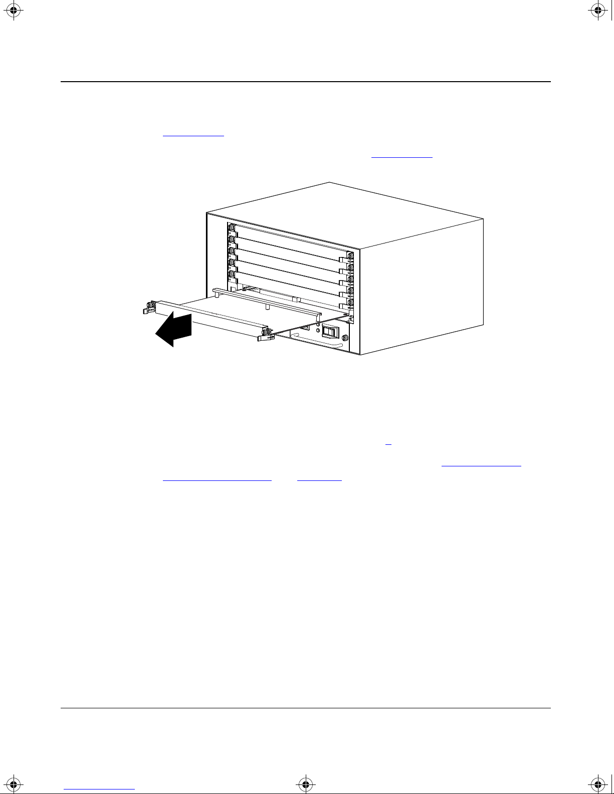
Slide the module out of the chassis (see Figure 3-10).
6.
Installing and Connecting the TokenSpeed Module
6471
Figure 3-10. Removing the module from the switch chassis
If you will not be replacing the module soon, attach a filler panel o ver the
7.
empty slot. Otherwise, continue with step 8
.
8. Install the new module, following the instructions in “Installing the
TokenSpeed Module” on page 3-2.
9. Turn on the power to the switch.
10. Download the saved configuration file to the new module.
For module configuration instructions and for instructions on saving and
downloading files, refer to Using SpeedView 2.1 for Windows.
893-01019-A 3-13

TKNSPD.BK Page 14 Thursday, July 17, 1997 11:43 AM
Using the 8-port TokenSpeed and TokenSpeed/MCP Switch Modules
Replacing a TokenSpeed Module
You do not need to turn off the switch power before you replace a TokenSpeed
module that does not have an MCP.
To replace a TokenSpeed module, follow these steps:
1. Disable all ports on the module using SpeedView, or disconnect the cables
from each port.
Disabling the ports on a module is described in Using SpeedView 2.1 for
Windows.
2. Wait 45 seconds.
Waiting allows the system software to process the requests to disable the
ports.
Caution: If you remove a module without waiting 45 seconds after disabling
the ports, you must power cycle the Centillion switch chassis. When you turn
off the power on the Centillion switch chassis, you must w ait 15 to 20 seconds
before turning the power back on. The TokenSpeed modules begin switching
an additional 15 to 20 seconds after power is resumed.
3. Loosen the two retaining screws on the module until they pop free of the
chassis frame (see Figur
e 3-11).
Figure 3-11. Loosening the TokenSpeed module
3-14 893-01019-A
6470
TKNSPD.BK Page 15 Thursday, July 17, 1997 11:43 AM
Rotate the left and right inserter/extractor levers away from the center of
4.
the module to loosen the module from the backplane connectors (see
e 3-11).
Figur
5. Slide the module out of the chassis (see Figure 3-12).
Installing and Connecting the TokenSpeed Module
6471
Figure 3-12. Removing the module from the Centillion chassis
If you will not be replacing the module soon, attach a filler panel o ver the
6.
empty slot. Otherwise, continue with step 7
.
7. Install the new module, following the instructions in “Installing the
TokenSpeed Module” on page 3-2.
893-01019-A 3-15

TKNSPD.BK Page 16 Thursday, July 17, 1997 11:43 AM

TKNSPD.BK Page 1 Thursday, July 17, 1997 11:43 AM
Troubleshooting the TokenSpeed Module
This chapter provides suggestions for troubleshooting the TokenSpeed module.
This chapter covers the following topics:
Chapter 4
• Switch startup failure (see page
• Module startup failure (see page
• Port insertion problems (see page
To expedite support when you call Bay Networks, please have the following
information ready:
• Hardware configuration
• Software configuration (including the image file version number and
SpeedView version number)
• Network diagram
• Module or switch part number and serial number for the suspected unit
• Brief description of the problem
4-2)
4-3)
4-4)
893-01019-A 4-1

TKNSPD.BK Page 2 Thursday, July 17, 1997 11:43 AM
Using the 8-port TokenSpeed and TokenSpeed/MCP Switch Modules
Switch Startup Failure with TokenSpeed/MCP
Symptom: The startup process halts, and the module LEDs remain lit.
If the code image stored in flash memory becomes corrupted, the checksum fails
during reset. You must perform an emergency image download.
To load and start the switch with the switch image provided on the Centillion
Switch Images diskette, follow these steps:
1. Locate the Centillion Switch Images diskette that was shipped with your
SpeedView software.
2. Connect a SpeedView station to the serial port of the TokenSpeed/MCP
module, using either the direct connection or the modem connection.
This procedure is described in Using SpeedView 2.1 for Windows.
3. Verify through the command line interface (CLI) that the switch is
unable to start.
a. Close SpeedView and run a terminal emulation pr ogram to access the
CLI.
For more information, refer to Reference Guide for the Centillion
Command Line Interface.
b. If the switch is unable to start, the screen does not display the CLI
prompt. Instead, the following message is displayed:
Is there anyone out there?
4. Quit the terminal emulation program and start SpeedView.
5. Verify that the serial port is selected in the Preferences dialog box.
6. Select the Map menu, and then choose Discover.
The discovery process completes in a few seconds. A map window with no
icons is displayed.
7. Select the Switch menu, and then choose Download Software.
8. Select the switch image file, and then click on Open.
The Software Download dialog box is displayed. For detailed information
about this dialog box and the software download procedure, refer to Using
SpeedView 2.1 for Windows.
4-2 893-01019-A

TKNSPD.BK Page 3 Thursday, July 17, 1997 11:43 AM
Click on the Start button in the Software Download dialog box.
9.
If the display returns to the Main Menu instead of displaying the “Writing to
Flash” message, the download process did not complete successfully.
10. If you are not prompted to reset the switch, choose Discover again.
11. Click on the icon for the switch and choose Download software.
When the download is complete, the following message is displayed:
Writing to Flash...
The switch begins executing the loaded switch image and prompts you to
reset the switch.
12. Choose Reset to verify that the downloaded image is installed properly.
Troubleshooting the TokenSpeed Module
When the switch completes the reset and starts operating properly, you may
continue normal operation. If the reset is unsuccessful or an error indication
appears, repeat the entire procedure. If it fails again, call Bay Networks customer
support. Please be ready to provide the service representative with the information
listed on page
4-1.
TokenSpeed Module Startup Failure
Symptom: The switch startup process completes successfully, but the Activity
LED blinks continually.
To resolve the problem, follow these steps:
1. Check all modules in the chassis to make sure they are firmly seated and
that the retaining screws are tight.
2. Remove and reinsert the failing module.
If the problem persists, contact Bay Networks customer support. Please be ready
to provide the service representative with the information listed on page
4-1.
893-01019-A 4-3

TKNSPD.BK Page 4 Thursday, July 17, 1997 11:43 AM
Using the 8-port TokenSpeed and TokenSpeed/MCP Switch Modules
Port Insertion Problems
Symptom: The Act LED on a token ring port does not flash for a period of 15 to
20 seconds.
No flashing on the Act LED on a token ring port typically indicates port insertion
problems.
To resolve the problem, follow these steps:
1. Verify that the port is not operational by accessing the SpeedView
multicast frame transmit and receive count statistics (Mcst xmit and
Mcst rcv). Verify that the statistics are updating regularly over a period
of 15 to 20 seconds.
If the counts change, the token ring port is inserted and operating. If the port
is operating but the Activity LED stays dark, the LED may be damaged.
If the counts do not change, the token ring port is not inserted or enabled.
Proceed to the following steps to verify proper installation, configuration, and
connection for the port.
2. Verify that the cabling is correct.
See Appendix
B, “Cables,” for information about the token ring port types
and pin assignments for different connectors.
3. Using SpeedView, verify the following items:
• The appropriate port type is configured: Station, Hub, Bay/SNPX RO,
RI–other, or RO–other.
For more information about setting port types, see “
Token Ring
Connections” on page 3-6.
• The port is enabled.
4-4 893-01019-A

TKNSPD.BK Page 5 Thursday, July 17, 1997 11:43 AM
• Port speed and speed sensing are configured appropriately.
– If the port speed is not set to Auto, and Speed Sense is disabled,
the port is forced to operate at a particular speed. Verify that the
configured speed matches the actual speed of the ring.
– If Speed Sense is enabled, be sure that at least one device on the
connected ring is not set to Speed Sense.
– If the switch is connected to an intelligent hub that has automatic
speed sensing, such as a Bay Networks hub, configure a specific
speed for the port on the TokenSpeed module and disable the
Speed Sense option.
• The ring number assigned to this port does not conflict with other ring
numbers in the network.
Troubleshooting the TokenSpeed Module
If the ring parameter server tells the port a different ring number from the
number that is configured, the port will deinsert.
4. Disable the port; then enable it again.
5. If the port still fails to insert, try inserting the port into another ring
segment.
If the second port inserts successfully, check the status of the first ring.
If the second port fails to insert into the other ring, contact Bay Networks
customer support. Please be ready to provide the service representative with
the information listed on page 4-1.
893-01019-A 4-5

TKNSPD.BK Page 6 Thursday, July 17, 1997 11:43 AM

TKNSPD.BK Page 1 Thursday, July 17, 1997 11:43 AM
This appendix provides technical specifications for the TokenSpeed module.
Data Rate
Appendix A
Technical Specifications
4 Mb/s or 16 Mb/s, IEEE 802.5
Microprocessors
Baseboard:64-bit MIPS 4000 series processor, 100 MHz (MIPS)
Memory
Processor 2 MB (TokenSpeed module)
10 MB (TokenSpeed/MCP module)
Buffer pool 1 MB
Flash 128 KB (TokenSpeed module)
2.5 MB (TokenSpeed/MCP module)
Electrical Specifications
Power consumption: 45 W maximum
Thermal rating 155 BTU/hr maximum
Physical Specifications
Dimensions (L) 10.5 by (W) 12.5 by (H) 1.0 in.
(L) 26.7 by (W) 31.7 by (H) 2.5 cm
Weight 3.0 lb (1.36 kg) (TokenSpeed module)
3.1 lb (1.41 kg) (TokenSpeed/MCP module)
893-01019-A A-1

TKNSPD.BK Page 2 Thursday, July 17, 1997 11:43 AM
Using the 8-port TokenSpeed and TokenSpeed/MCP Switch Modules
Environmental Specifications
Operating temperature 0° to 40° C
Storage temperature –25° to 70° C
Operating humidity 85% maximum relative humidity, noncondensing
Storage humidity 95% maximum relative humidity, noncondensing
Operating altitude 10,000 ft (3,000 m) maximum
Storage altitude 10,000 ft (3,000 m) maximum
Free fall/drop ISO 4180-s, NSTA 1A
Vibration IEC 68-2-6/34
Shock/bump IEC 68-2-27-29
Electromagnetic Emissions
Meets requirements of:
FCC Part 15, Subpart B, Class A
EN 55 022 (CISPR 22:1985), Class A
VCCI Class 1 ITE
Electromagnetic Susceptibility
Electrostatic discharge (ESD) EC 801-2, Level 2
Radiated electromagnetic field EC 801-2, Level 2
Electrical fast transient/burst EC 801-4, Level 2
Electrical surge IEC 801-5, Level 1/2
Safety Agency Approvals
UL/CUL listed (UL 1950)
CSA certified (CSA 22.2 #950)
TUV licensed (EN 60 950)
UL-94-V1 flammability requirements for all PC boards
Connectors
RJ-45 connectors for UTP/STP interface
Mini DIN 8 serial connector for network administration (TokenSpeed/MCP only)
A-2 893-01019-A

TKNSPD.BK Page 1 Thursday, July 17, 1997 11:43 AM
This appendix provides cable wiring information for TokenSpeed module port
connections. When you connect network devices to the TokenSpeed module, you
must specify the port type through SpeedView and use a straight-through cable
with an RJ-45 connector for the connection to the module port. The requirements
for the far-end connector v ary according to the type of device you are connecting.
Appendix B
Cables
This appendix includes information about the following topics:
• Port type settings for the token ring ports (see page
• Cable types for connecting token ring network devices to the TokenSpeed
module (see page
• Pin locations for the RJ-45 connectors on the TokenSpeed module
(see page
• Pin assignments for cables used to connect token ring network devices
(see page
• Connector pin assignments for the male Mini DIN 8 to male DB-25 cable
and female DB-25 to female DB-9 adapter for serial MCP connections
(see page
B-3)
B-4)
B-13)
B-2)
B-2)
893-01019-A B-1

TKNSPD.BK Page 2 Thursday, July 17, 1997 11:43 AM
Using the 8-port TokenSpeed and TokenSpeed/MCP Switch Modules
Port Types
When you connect a network device to a token ring port on the TokenSpeed
module, you must specify a TokenSpeed port type through SpeedView. The port
type setting is based on the type of network connection you are connecting to the
TokenSpeed module. T
correct port type for each.
Table B-1. Port types for the TokenSpeed module
Network device port TokenSpeed port type
Lobe port on token ring hub Station
Lobe port on IBM 8228 MAU or similar device Station
able B-1 shows the types of network connections and the
Station port on a network interface card (NIC)
in a server, PC, or router
RI port on a Bay Networks token ring hub Bay/SNPX RO
RO port on a Bay Networks token ring hub RI–other
RI port on a non-Bay Networks token ring hub RO–other
RO port on a non-Bay Networks token ring hub RI–other
Cable Types
The following types of cables are used to make connections to the TokenSpeed
module:
• Category 3, 4, or 5 UTP cable with an RJ-45 connector on one end and an
• Type 1A STP cable with an RJ-45 connector on one end and an appropriate
Hub
Note: The RO port type on the
Bay Networks hub must be set as
Other.
appropriate connector on the other end for the device you are connecting to
the TokenSpeed module
connector on the other end for the device you are connecting to the
TokenSpeed module
• Serial MCP cable that is shipped with the Centillion switch
B-2 893-01019-A

TKNSPD.BK Page 3 Thursday, July 17, 1997 11:43 AM
Table B-2 shows maximum distances for cables used in a token ring network that
includes the TokenSpeed module.
Table B-2. Cable distances
Cable type 4 Mb/s 16 Mb/s
UTP cable type
Category 3 DIW 200 m 100 m
Category 4 375 m 150 m
Category 5 400 m 200 m
STP cable type
1, 1A, 2 900 m 450 m
6, 9 600 m 300 m
Cables
8 400 m 200 m
Note: These distances are accurate only for connection to and from active hubs
and stations. For connections to a passive device, refer to the documentation that
was shipped with that product.
Token Ring Connectors on the TokenSpeed Module
The token ring ports on the TokenSpeed module have RJ-45 sockets with the pin
numbers and locations shown in Figure
typical connector on a network adapter that is used in a station device or network
node.
1 2 3 4 5 6 7 8
B-1. This connector is equivalent to the
4026
Figure B-1. RJ-45 connector on the TokenSpeed module
893-01019-A B-3

TKNSPD.BK Page 4 Thursday, July 17, 1997 11:43 AM
Using the 8-port TokenSpeed and TokenSpeed/MCP Switch Modules
Cable and Connector Pin Assignments
This section provides the pin assignments for connectors typically used to connect
network devices to the TokenSpeed module. For each connection type, the
illustrations show the TokenSpeed port type, pin numbers, signal, and phantom
source. All cables are shown as straight-through cables because the correct port
type setting on the TokenSpeed module automatically adjusts the port for any
needed crossover function.
The end that connects to the TokenSpeed module is an RJ-45 connector. The
connector at the other end can be another RJ-45 connector, a DB-9 connector, or
an IBM Type 1 connector (see Figure
B-2).
1 2 3 4 5 6 7 8
4026
5
9
1
6
7578EA
Figure B-2. Connectors for token ring network cables
Pin 1 (Black)
3041FC
B-4 893-01019-A
TKNSPD.BK Page 5 Thursday, July 17, 1997 11:43 AM
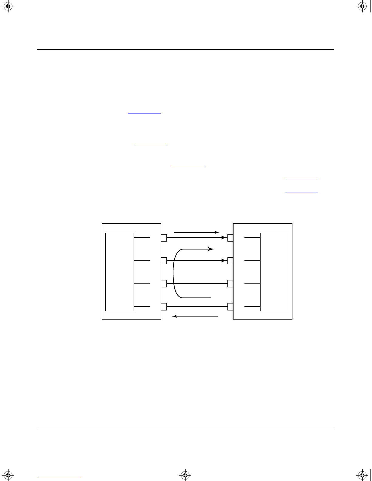
RJ-45 to RJ-45 Connection
The figures in this section show cable wiring for the following types of RJ-45 to
RJ-45 connection:
• TokenSpeed Hub port type connected to a station port in a network adapter
card (see Figure
• TokenSpeed Station port type connected to a lobe port on a token ring hub,
such as a Bay Networks Model 2715 token ring hub or an IBM 8228-style
device (see Figure
• TokenSpeed Bay/SNPX RO port type connected to an RI port on a
Bay Networks hub (see Figure
Cables
B-3)
B-4)
B-5)
• TokenSpeed RI–other port type connected to an RO port (see Figure
• TokenSpeed RO–other port type connected to an RI port (see Figure
TokenSpeed port
RJ-45 RJ-45
Data direction
TX
4
TX
RX
RX
5
Phantom
direction
3
6
Data direction
TokenSpeed
port type:
Hub
Phantom
sense
Figure B-3. Hub to station connection (RJ-45 to RJ-45)
Customer equipment
RX
4
RX
5
Phantom
TX
3
TX
6
source
B-6)
B-7)
Network device
port type:
Station
7602EB
893-01019-A B-5

TKNSPD.BK Page 6 Thursday, July 17, 1997 11:43 AM
Using the 8-port TokenSpeed and TokenSpeed/MCP Switch Modules
TokenSpeed port Customer equipment
RJ-45 RJ-45
Data direction
RX
4
TX
4
TokenSpeed
port type:
Station
Figure B-4. Station to hub connection (RJ-45 to RJ-45)
TokenSpeed
port type:
Bay/SNPX RO
Phantom
source
TokenSpeed port
Phantom
sense
RX
5
Phantom
direction
TX
3
6
TX
RJ-45 RJ-45
TX
TX
RX
Data direction
Data direction
4
5
Phantom
direction
3
TX
5
Phantom
RX
3
RX
6
Customer equipment
(Bay Networks hub)
RX
4
RX
5
Phantom
source
TX
3
sense
Network device
port type:
Hub
7603EB
Network device
port type:
RI
Figure B-5. Bay/SNPX RO to RI connection (RJ-45 to RJ-45)
B-6 893-01019-A
RX
6
Data direction
TX
6
7604EB

TKNSPD.BK Page 7 Thursday, July 17, 1997 11:43 AM
TokenSpeed port Customer equipment
RJ-45 RJ-45
Data direction
RX
4
Cables
TX
4
TokenSpeed
port type:
RI-other
RX
TX
TX
5
3
6
Data direction
TX
5
RX
3
RX
6
Figure B-6. RI–other to RO connection (RJ-45 to RJ-45)
TokenSpeed port Customer equipment
RJ-45 RJ-45
Data direction
TokenSpeed
port type:
RO-other
TX
TX
RX
4
5
3
RX
4
RX
5
TX
3
Network device
port type:
RO
7684EB
Network device
port type:
RI
Figure B-7. RO–other to RI connection (RJ-45 to RJ-45)
893-01019-A B-7
RX
6
Data direction
TX
6
7605EB

TKNSPD.BK Page 8 Thursday, July 17, 1997 11:43 AM
Using the 8-port TokenSpeed and TokenSpeed/MCP Switch Modules
RJ-45 to DB-9 Connection
The figures in this section show cable wiring for the following types of RJ-45
to DB-9 connection:
• TokenSpeed Hub port type connected to a station port in a network adapter
card (see Figure
• TokenSpeed Station port type connected to a lobe port on a token ring hub,
such as a Bay Networks Model 2715 token ring hub or an IBM 8228-style
device (see Figure
• TokenSpeed Bay/SNPX RO port type connected to an RI port on a
Bay Networks hub (see Figure
B-8)
B-9)
B-10)
• TokenSpeed RI–other port type connected to an RO port (see Figure
• TokenSpeed RO–other port type connected to an RI port (see Figure
TokenSpeed
port type:
Hub
Figure B-8. Hub to station connection (RJ-45 to DB-9)
TokenSpeed port Customer equipment
Phantom
sense
RJ-45 DB-9
Data direction
TX
4
TX
5
Phantom
direction
3
RX
6
RX
Data direction
RX
1
RX
6
Phantom
source
TX
5
TX
9
B-11)
B-12)
Network device
port type:
Station
7606EB
B-8 893-01019-A

TKNSPD.BK Page 9 Thursday, July 17, 1997 11:43 AM
TokenSpeed port Customer equipment
RJ-45 DB-9
Data direction
RX
4
Cables
TX
1
TokenSpeed
port type:
Station
Figure B-9. Station to hub connection (RJ-45 to DB-9)
TokenSpeed
port type:
Bay/SNPX RO
Phantom
source
TokenSpeed port
Phantom
sense
RX
5
Phantom
direction
3
TX
6
TX
RJ-45 DB-9
TX
TX
RX
Data direction
Data direction
4
5
Phantom
direction
3
TX
6
Phantom
RX
5
RX
9
Customer equipment
(Bay Networks hub)
RX
1
RX
6
Phantom
source
TX
5
sense
Network device
port type:
Hub
7607EB
Network device
port type:
RI
Figure B-10. Bay/SNPX RO to RI connection (RJ-45 to DB-9)
893-01019-A B-9
RX
6
Data direction
TX
9
7608EB

TKNSPD.BK Page 10 Thursday, July 17, 1997 11:43 AM
Using the 8-port TokenSpeed and TokenSpeed/MCP Switch Modules
TokenSpeed port Customer equipment
RJ-45 DB-9
Data direction
RX
4
TX
1
TokenSpeed
port type:
RI-other
Figure B-11. RI–other to RO connection (RJ-45 to DB-9)
TokenSpeed
port type:
RO-other
RX
5
TX
3
6
TX
TokenSpeed port Customer equipment
RJ-45 DB-9
TX
TX
RX
Data direction
Data direction
4
5
3
TX
6
RX
5
RX
9
RX
1
RX
6
TX
5
Network device
port type:
RO
7609EB
Network device
port type:
RI
Figure B-12. RO–other to RI connection (RJ-45 to DB-9)
B-10 893-01019-A
RX
6
Data direction
TX
9
7685EB

TKNSPD.BK Page 11 Thursday, July 17, 1997 11:43 AM
RJ-45 to IBM Type 1 Connection
The figures in this section show cable wiring for the following types of RJ-45 to
IBM Type 1 connection:
• TokenSpeed Station port type connected to a lobe port on a token ring hub,
such as a Bay Networks Model 2715 token ring hub or an IBM 8228-style
device (see Figure
• TokenSpeed Bay/SNPX RO port type connected to an RI port on a
Bay Networks hub (see Figure
Cables
B-13)
B-14)
• TokenSpeed RI–other port type connected to an RO port (see Figure
• TokenSpeed RO–other port type connected to an RI port (see Figure
TokenSpeed port Customer equipment
RJ-45 Type1
Data direction
RX
4
RX
TX
TX
5
Phantom
direction
3
6
Data direction
TokenSpeed
port type:
Station
Phantom
source
Figure B-13. Station to hub connection (RJ-45 to IBM Type 1)
TX
R
TX
G
Phantom
RX
B
RX
O
sense
B-15)
B-16)
Network device
port type:
Hub
7611EB
893-01019-A B-11

TKNSPD.BK Page 12 Thursday, July 17, 1997 11:43 AM
Using the 8-port TokenSpeed and TokenSpeed/MCP Switch Modules
TokenSpeed
port type:
Bay/SNPX RO
Figure B-14. Bay/SNPX RO to RI connection (RJ-45 to IBM Type 1)
TokenSpeed port
Phantom
sense
TokenSpeed port Customer equipment
RJ-45 Type1
Data direction
TX
4
TX
5
Phantom
direction
3
RX
6
RX
RJ-45 Type1
Data direction
Customer equipment
(Bay Networks hub)
RX
R
RX
G
Phantom
TX
B
TX
O
source
Network device
port type:
RI
7612EB
Data direction
TokenSpeed
port type:
RI-other
RX
RX
TX
TX
4
5
3
6
Data direction
TX
R
TX
G
RX
B
RX
O
Figure B-15. RI–other to RO connection (RJ-45 to IBM Type 1)
Network device
port type:
RO
7613EB
B-12 893-01019-A
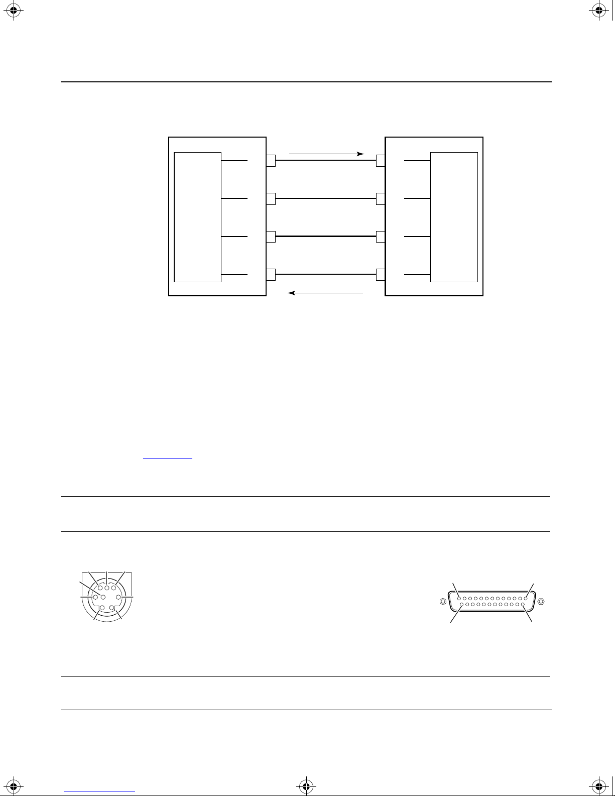
TKNSPD.BK Page 13 Thursday, July 17, 1997 11:43 AM
TokenSpeed port Customer equipment
RJ-45 Type1
Data direction
TX
4
Cables
RX
R
TX
RX
RX
5
3
6
Data direction
TokenSpeed
port type:
RO-other
Figure B-16. RO–other to RI connection (RJ-45 to IBM Type 1)
Serial MCP Connections
The Centillion chassis package includes a male Mini DIN 8 to male DB-25 cable
and a female DB-25 to female DB-9 adapter for serial MCP connections.
This section describes these components.
able B-3 shows the connections for a male Mini DIN 8 to male DB-25 cable.
T
Table B-3. Male Mini DIN 8 to male DB-25 cable
RX
G
TX
B
TX
O
Network device
port type:
RI
7686EB
Male Mini DIN
8 pin locations
Male Mini DIN
8 pin numbers
1 Reserved
6 8
4
3
7
2 Data terminal ready 20
3 Transmit data 3
4 Signal ground 7
5
5 Receive data 2
1
2
6741.1
6 Reserved
7—Not connected
8 Reserved
893-01019-A B-13
Signal
Male DB-25
pin numbers
Male DB-25
pin locations
1
14 25
2206EE
13

TKNSPD.BK Page 14 Thursday, July 17, 1997 11:43 AM
Using the 8-port TokenSpeed and TokenSpeed/MCP Switch Modules
Table B-4 shows the connections for a female DB-25 to female DB-9 adapter.
Table B-4. Female DB-25 to female DB-9 adapter
Female DB-25 pin
locations
13 1
25
14
7579EA
Female
DB-25 pin
Signal
numbers
8 Data carrier detect 1
3 Receive data 2
2 Transmit data 3
20 Data terminal ready 4
7 Signal ground 5
6 Data set ready 6
4 Request to send 7
5 Clear to send 8
22 Ring indicator 9
Female DB-9
pin numbers
Female DB-9
pin locations
5
9
1
6
7578EA
B-14 893-01019-A

TKNSPD.BK Page 1 Thursday, July 17, 1997 11:43 AM
A
Act LED, 3-8
antistatic precautions, 3-2
application examples, 2-1
ARE hop count parameter, 3-10
B
Bay Networks Press, xv
Bay Networks World Wide Web page, xvii
BootP, 1-4
Bridge group parameter, 3-10
C
cables
female DB-25 to female DB-9 adapter
length, B-3
male Mini DIN 8 to male DB-25, B-13
serial MCP, 3-7, B-13
types, B-2
caching, RIF, 1-3
configurations
factory default
predefined, 3-10
connections
management station
RJ-45 to DB-9, B-8
RJ-45 to IBM Type 1, B-11
RJ-45 to RJ-45, B-5
serial MCP, B-13
, 3-9
, 3-7
, B-14
connectors
for network devices
MCP, 3-7
Mini DIN 8, B-13
RJ-45, 1-1, 3-6, B-3
TokenSpeed, 1-2
conventions, xiv
customer support, xvi
, B-4
D
data rate, A-1
datagram broadcast filters, 1-3
Declaration of Conformity, iii
dedicated port for server, 2-1
default switch configuration, 3-9
download process, incomplete, 4-3
E
electrical specifications, A-1
electromagnetic emissions, A-2
electromagnetic susceptibility, A-2
emergency image download, 4-2
environmental specifications, A-2
example networks
concentrating rings into a router
dedicated port for a server, 2-1
replacing source route bridge or router, 2-5
segmenting a ring, 2-2
, 2-5
Index
893-01019-A Index-1

TKNSPD.BK Page 2 Thursday, July 17, 1997 11:43 AM
F
failure
module startup
port insertion, 4-4
TokenSpeed/MCP module, 4-2
fault tolerance, 1-3
filtering features, 1-3
Filters parameter, 3-10
, 4-3
H
hop count, 3-10
hot swapping, 1-3, 3-2
I
image, downloading, 4-2
incomplete download process, 4-3
Ins LED, 3-8
installation
instructions
tools and materials, 3-1
verifying, 3-7
, 3-2
L
LEDs, 3-8
M
MAU, 2-3
MCP (master control processor), 1-1
MCP cable, 3-7
MCP port, connecting, 3-7
media attachment unit. See MAU
memory
microprocessor, A-1
Mini DIN 8 connector, 3-7, B-13
modules
, A-1
description
installing, 3-2
replacing, 3-11
, 1-1
N
name query interval, 1-3
NetBIOS name filters, 1-3
network management features, 1-3
network management station, 1-1, 3-7
P
Path cost parameter, 3-10
physical specifications, A-1
pin assignments
DB-9 connections
IBM Type 1 connections, B-11
RJ-45 connections, B-5
serial MCP connections, B-13
port
features
insertion failure, 4-4
lobe, 2-4
Mini DIN 8, 3-7
priority, 3-10
RI or RO, 2-3
RJ-45, 3-6
state, 3-9
types, 3-9, B-2
Port type parameter, 3-9
port-to-port switching, 1-2
publications
ordering
related, xv
, 1-2
, xv
, B-8
Index-2 893-01019-A

TKNSPD.BK Page 3 Thursday, July 17, 1997 11:43 AM
R
related publications, xv
RI port, 2-3
RIF caching, 1-3
Ring speed parameter, 3-9
ring, segmenting, 2-2
rings, concentrating into a router, 2-5
RJ-45 connector, B-3
RJ-45 to DB-9 connection, B-8
RJ-45 to IBM Type 1 connection, B-11
RJ-45 to RJ-45 connection, B-5
RO port, 2-3
routers
concentrating rings into
replacing, 2-5
, 2-5
S
safety agency approvals, A-2
server, dedicating a port to, 2-1
SNMP agent, 1-3
software download, 4-2
source route bridges, replacing, 2-5
source route bridging, 1-2
source route broadcasting, 3-10
source route explorer proxy, 1-3
source route transparent bridging, 1-2
Spanning Tree Protocol parameter, 3-9
Spanning Tree support, 1-2
Speed sense parameter, 3-9
SpeedView, 1-4
SR broadcasting parameter, 3-10
startup failure, 4-2
startup sequence, LEDs, 3-8
State parameter, 3-9
STE hop count parameter, 3-10
Switching mode parameter, 3-9
switching, IEEE 802.1d, 1-2
T
Technical Solutions Centers, xvi
technical specifications, A-1
technical support, xvi
TFTP, 1-4
token ring connection
segmenting a ring
selecting port type, B-2
servers, 2-1
TokenSpeed ports
connectors
insertion problems, 4-4
TokenSpeed/MCP module, replacing, 3-12
transparent bridging, 1-2
troubleshooting, 4-1
, 2-2
, 1-1, 1-2
V
Virtual ring number parameter, 3-10
virtual ring partitioning, 1-2
virtual rings, 2-5, 3-10
W
World Wide Web page, Bay Networks, xvii
893-01019-A Index-3

TKNSPD.BK Page 4 Thursday, July 17, 1997 11:43 AM
 Loading...