

Page 1

Remote Annex
T1 Getting Started Guide
Part No. 166-024-851 Rev. A
January 1997
Page 2

Copyright © 1997 Bay Networks, Inc.
All rights reserved. Printed in the USA. January 1997.
The information in this document is subject to change without notice. The statements, configurations, technical data, and
recommendations in this document are believed to be accurate and reliable, b ut are presented without express or implied
warranty. Users must take full responsibility for their applications of any products specified in this document. The
information in this document is proprietary to Bay Networks, Inc.
The software described in this document is furnished under a license agreement and may only be used in accordance with
the terms of that license.
Restricted Rights Legend
Use, duplication, or disclosure by the United States Government is subject to restrictions as set forth in subparagraph
(c)(1)(ii) of the Rights in Technical Data and Computer Software clause at DFARS 252.227-7013.
Notice for All Other Executive Agencies
Notwithstanding any other license agreement that may pertain to, or accompany the deli very of, this computer softw are,
the rights of the United States Government regarding its use, reproduction, and disclosure are as set forth in the Commercial
Computer Software-Restricted Rights clause at FAR 52.227-19.
Trademarks of Bay Networks, Inc.
Annex, Remote Annex, Annex Manager , Remote Annex 2000, Remote Annex 4000, Remote Anne x 6100, Remote Annex
6300, Remote Annex 5390/Async, Remote Annex 5391/CT1, Remote Annex 5393/PRI, BayStack Remote Anne x 2000
Server,Quick2Config, Bay Networks, Bay Networks Press, and the Bay Networks logo are trademarks of Bay Networks,
Inc.
Third Party Trademarks
Portions subject to copyright by Microcom Systems, Inc. 1993-1997. Used by permission.
All other trademarks and registered trademarks are the property of their respective owners.
Statement of Conditions
In the interest of improving internal design, operational function, and/or reliability , Bay Netw orks, Inc. reserves the right
to make changes to the products described in this document without notice.
Bay Networks, Inc. does not assume any liability that may occur due to the use or application of the product(s) or circuit
layout(s) described herein.
In addition, the program and information contained herein are licensed only pursuant to a license agreement that contains
restrictions on use and disclosure (that may incorporate by reference certain limitations and notices imposed by third
parties).
Page 3

Revision Description
A Initial release.
Revision Level History
iiiT1 Getting Started Guide
Page 4

Revision Level History
iv
T1 Getting Started Guide
Page 5

Contents
Preface
About this Guide. . . . . . . . . . . . . . . . . . . . . . . . . . . . . . . . . . . . . . . . . . . . . . . . . . . . . . . . . . . . . . . . . . . . . . . . . . . . xii
Printing Conventions. . . . . . . . . . . . . . . . . . . . . . . . . . . . . . . . . . . . . . . . . . . . . . . . . . . . . . . . . . . . . . . . . . . . . . . . . xii
Related Documents . . . . . . . . . . . . . . . . . . . . . . . . . . . . . . . . . . . . . . . . . . . . . . . . . . . . . . . . . . . . . . . . . . . . . . . . xiii
Chapter 1
Introduction
T1 Digital Transmission System . . . . . . . . . . . . . . . . . . . . . . . . . . . . . . . . . . . . . . . . . . . . . . . . . . . . . . . . . . . . . . . 1-1
The Remote Annex 6100 . . . . . . . . . . . . . . . . . . . . . . . . . . . . . . . . . . . . . . . . . . . . . . . . . . . . . . . . . . . . . . . . . . . . 1-3
Chapter 2
Commands and Parameters
T1 Commands . . . . . . . . . . . . . . . . . . . . . . . . . . . . . . . . . . . . . . . . . . . . . . . . . . . . . . . . . . . . . . . . . . . . . . . . . . . . 2-1
stats -T . . . . . . . . . . . . . . . . . . . . . . . . . . . . . . . . . . . . . . . . . . . . . . . . . . . . . . . . . . . . . . . . . . . . . . . . . . . . . . 2-2
t1_loopback. . . . . . . . . . . . . . . . . . . . . . . . . . . . . . . . . . . . . . . . . . . . . . . . . . . . . . . . . . . . . . . . . . . . . . . . . . . 2-8
reset . . . . . . . . . . . . . . . . . . . . . . . . . . . . . . . . . . . . . . . . . . . . . . . . . . . . . . . . . . . . . . . . . . . . . . . . . . . . . . . 2-10
set t1 . . . . . . . . . . . . . . . . . . . . . . . . . . . . . . . . . . . . . . . . . . . . . . . . . . . . . . . . . . . . . . . . . . . . . . . . . . . . . . . 2-12
show t1 . . . . . . . . . . . . . . . . . . . . . . . . . . . . . . . . . . . . . . . . . . . . . . . . . . . . . . . . . . . . . . . . . . . . . . . . . . . . . 2-13
T1 Parameters . . . . . . . . . . . . . . . . . . . . . . . . . . . . . . . . . . . . . . . . . . . . . . . . . . . . . . . . . . . . . . . . . . . . . . . . . . . 2-14
alarmsyslog. . . . . . . . . . . . . . . . . . . . . . . . . . . . . . . . . . . . . . . . . . . . . . . . . . . . . . . . . . . . . . . . . . . . . . . . . . 2-15
bypass. . . . . . . . . . . . . . . . . . . . . . . . . . . . . . . . . . . . . . . . . . . . . . . . . . . . . . . . . . . . . . . . . . . . . . . . . . . . . . 2-16
map. . . . . . . . . . . . . . . . . . . . . . . . . . . . . . . . . . . . . . . . . . . . . . . . . . . . . . . . . . . . . . . . . . . . . . . . . . . . . . . . 2-17
ring . . . . . . . . . . . . . . . . . . . . . . . . . . . . . . . . . . . . . . . . . . . . . . . . . . . . . . . . . . . . . . . . . . . . . . . . . . . . . . . . 2-22
sigproto . . . . . . . . . . . . . . . . . . . . . . . . . . . . . . . . . . . . . . . . . . . . . . . . . . . . . . . . . . . . . . . . . . . . . . . . . . . . . 2-23
switch_type . . . . . . . . . . . . . . . . . . . . . . . . . . . . . . . . . . . . . . . . . . . . . . . . . . . . . . . . . . . . . . . . . . . . . . . . . . 2-25
t1_info . . . . . . . . . . . . . . . . . . . . . . . . . . . . . . . . . . . . . . . . . . . . . . . . . . . . . . . . . . . . . . . . . . . . . . . . . . . . . . 2-26
tdi_distance. . . . . . . . . . . . . . . . . . . . . . . . . . . . . . . . . . . . . . . . . . . . . . . . . . . . . . . . . . . . . . . . . . . . . . . . . . 2-27
tdi_framing . . . . . . . . . . . . . . . . . . . . . . . . . . . . . . . . . . . . . . . . . . . . . . . . . . . . . . . . . . . . . . . . . . . . . . . . . . 2-28
tdi_line_code. . . . . . . . . . . . . . . . . . . . . . . . . . . . . . . . . . . . . . . . . . . . . . . . . . . . . . . . . . . . . . . . . . . . . . . . . 2-29
tni_circuit_id . . . . . . . . . . . . . . . . . . . . . . . . . . . . . . . . . . . . . . . . . . . . . . . . . . . . . . . . . . . . . . . . . . . . . . . . . 2-30
tni_clock . . . . . . . . . . . . . . . . . . . . . . . . . . . . . . . . . . . . . . . . . . . . . . . . . . . . . . . . . . . . . . . . . . . . . . . . . . . . 2-31
tni_esf_fdl . . . . . . . . . . . . . . . . . . . . . . . . . . . . . . . . . . . . . . . . . . . . . . . . . . . . . . . . . . . . . . . . . . . . . . . . . . . 2-32
tni_framing . . . . . . . . . . . . . . . . . . . . . . . . . . . . . . . . . . . . . . . . . . . . . . . . . . . . . . . . . . . . . . . . . . . . . . . . . . 2-33
tni_line_buildout . . . . . . . . . . . . . . . . . . . . . . . . . . . . . . . . . . . . . . . . . . . . . . . . . . . . . . . . . . . . . . . . . . . . . . 2-34
tni_line_code. . . . . . . . . . . . . . . . . . . . . . . . . . . . . . . . . . . . . . . . . . . . . . . . . . . . . . . . . . . . . . . . . . . . . . . . . 2-35
tni_ones_density. . . . . . . . . . . . . . . . . . . . . . . . . . . . . . . . . . . . . . . . . . . . . . . . . . . . . . . . . . . . . . . . . . . . . . 2-36
T1-Specific Parameters vs. MIB Objects . . . . . . . . . . . . . . . . . . . . . . . . . . . . . . . . . . . . . . . . . . . . . . . . . . . . . . . 2-37
Chapter 3
Configuration
Configuring a T1 Connection . . . . . . . . . . . . . . . . . . . . . . . . . . . . . . . . . . . . . . . . . . . . . . . . . . . . . . . . . . . . . . . . . 3-1
Chapter 4
The Internal Modems
Features . . . . . . . . . . . . . . . . . . . . . . . . . . . . . . . . . . . . . . . . . . . . . . . . . . . . . . . . . . . . . . . . . . . . . . . . . . . . . . . . . 4-2
Using the AT Command Set. . . . . . . . . . . . . . . . . . . . . . . . . . . . . . . . . . . . . . . . . . . . . . . . . . . . . . . . . . . . . . . . . . 4-3
Entering AT Commands at Any Speed. . . . . . . . . . . . . . . . . . . . . . . . . . . . . . . . . . . . . . . . . . . . . . . . . . . . . . 4-3
vT1 Getting Started Guide
Page 6

Contents
Key AT Command Factory Defaults . . . . . . . . . . . . . . . . . . . . . . . . . . . . . . . . . . . . . . . . . . . . . . . . . . . . . . . . 4-4
Hanging Up. . . . . . . . . . . . . . . . . . . . . . . . . . . . . . . . . . . . . . . . . . . . . . . . . . . . . . . . . . . . . . . . . . . . . . . . . . . 4-6
Establishing 11-Bit Data Connections . . . . . . . . . . . . . . . . . . . . . . . . . . . . . . . . . . . . . . . . . . . . . . . . . . . . . . 4-6
V.32bis Cellular Connections Using AT Commands . . . . . . . . . . . . . . . . . . . . . . . . . . . . . . . . . . . . . . . . . . . 4-6
Universal Cellular Setup. . . . . . . . . . . . . . . . . . . . . . . . . . . . . . . . . . . . . . . . . . . . . . . . . . . . . . . . . . . . . . . . . 4-7
MNP 10 V.32bis Quick Connect Cellular Only Setup . . . . . . . . . . . . . . . . . . . . . . . . . . . . . . . . . . . . . . . . . . . 4-7
Additional connection speed enhancements . . . . . . . . . . . . . . . . . . . . . . . . . . . . . . . . . . . . . . . . . . . . . . . . . 4-8
Modulation Protocols . . . . . . . . . . . . . . . . . . . . . . . . . . . . . . . . . . . . . . . . . . . . . . . . . . . . . . . . . . . . . . . . . . . . . . . 4-8
Using Multi-Protocol Auto-Answer . . . . . . . . . . . . . . . . . . . . . . . . . . . . . . . . . . . . . . . . . . . . . . . . . . . . . . . . . 4-8
V.34 and V.FC . . . . . . . . . . . . . . . . . . . . . . . . . . . . . . . . . . . . . . . . . . . . . . . . . . . . . . . . . . . . . . . . . . . . . . . . 4-8
V.32 and V.32bis Protocols . . . . . . . . . . . . . . . . . . . . . . . . . . . . . . . . . . . . . . . . . . . . . . . . . . . . . . . . . . . . . . 4-9
V.23 Protocol . . . . . . . . . . . . . . . . . . . . . . . . . . . . . . . . . . . . . . . . . . . . . . . . . . . . . . . . . . . . . . . . . . . . . . . . 4-10
V.23 1,200 Bps Half-Duplex Operation. . . . . . . . . . . . . . . . . . . . . . . . . . . . . . . . . . . . . . . . . . . . . . . . . . . . . 4-10
V.22 and V.22bis Protocols . . . . . . . . . . . . . . . . . . . . . . . . . . . . . . . . . . . . . . . . . . . . . . . . . . . . . . . . . . . . . 4-11
V.21 Protocol . . . . . . . . . . . . . . . . . . . . . . . . . . . . . . . . . . . . . . . . . . . . . . . . . . . . . . . . . . . . . . . . . . . . . . . . 4-11
Bell 212A Protocol . . . . . . . . . . . . . . . . . . . . . . . . . . . . . . . . . . . . . . . . . . . . . . . . . . . . . . . . . . . . . . . . . . . . 4-12
Bell 103 Protocol. . . . . . . . . . . . . . . . . . . . . . . . . . . . . . . . . . . . . . . . . . . . . . . . . . . . . . . . . . . . . . . . . . . . . . 4-12
Protocol Configuration Command Settings. . . . . . . . . . . . . . . . . . . . . . . . . . . . . . . . . . . . . . . . . . . . . . . . . . 4-12
Speed and Protocol Connection Matrices . . . . . . . . . . . . . . . . . . . . . . . . . . . . . . . . . . . . . . . . . . . . . . . . . . 4-15
Error Correction . . . . . . . . . . . . . . . . . . . . . . . . . . . . . . . . . . . . . . . . . . . . . . . . . . . . . . . . . . . . . . . . . . . . . . . . . . 4-17
MNP Classes . . . . . . . . . . . . . . . . . . . . . . . . . . . . . . . . . . . . . . . . . . . . . . . . . . . . . . . . . . . . . . . . . . . . . . . . 4-17
Other Classes of MNP . . . . . . . . . . . . . . . . . . . . . . . . . . . . . . . . . . . . . . . . . . . . . . . . . . . . . . . . . . . . . . . . . 4-18
Diagnostics. . . . . . . . . . . . . . . . . . . . . . . . . . . . . . . . . . . . . . . . . . . . . . . . . . . . . . . . . . . . . . . . . . . . . . . . . . . . . . 4-19
Power-Up Diagnostics . . . . . . . . . . . . . . . . . . . . . . . . . . . . . . . . . . . . . . . . . . . . . . . . . . . . . . . . . . . . . . . . . 4-20
Local Analog Loopback with Self-Test . . . . . . . . . . . . . . . . . . . . . . . . . . . . . . . . . . . . . . . . . . . . . . . . . . . . . 4-20
Using Commands to Perform a Local Analog Loopback with Self-Test . . . . . . . . . . . . . . . . . . . . . . . . . . . . 4-20
Local Analog Loopback . . . . . . . . . . . . . . . . . . . . . . . . . . . . . . . . . . . . . . . . . . . . . . . . . . . . . . . . . . . . . . . . 4-21
Using Commands to Perform a Local Analog Loopback . . . . . . . . . . . . . . . . . . . . . . . . . . . . . . . . . . . . . . . 4-21
Remote Digital Loopback with Self-Test. . . . . . . . . . . . . . . . . . . . . . . . . . . . . . . . . . . . . . . . . . . . . . . . . . . . 4-22
Remote Digital Loopback . . . . . . . . . . . . . . . . . . . . . . . . . . . . . . . . . . . . . . . . . . . . . . . . . . . . . . . . . . . . . . . 4-23
Using Commands to Perform a Remote Digital Loopback . . . . . . . . . . . . . . . . . . . . . . . . . . . . . . . . . . . . . . 4-23
Local Digital Loopback . . . . . . . . . . . . . . . . . . . . . . . . . . . . . . . . . . . . . . . . . . . . . . . . . . . . . . . . . . . . . . . . . 4-24
Using Commands to Perform a Local Digital Loopback . . . . . . . . . . . . . . . . . . . . . . . . . . . . . . . . . . . . . . . . 4-24
Respond to Remote Digital Loopback . . . . . . . . . . . . . . . . . . . . . . . . . . . . . . . . . . . . . . . . . . . . . . . . . . . . . 4-25
Automatically Terminating a Test: Register S18. . . . . . . . . . . . . . . . . . . . . . . . . . . . . . . . . . . . . . . . . . . . . . 4-25
Result Codes . . . . . . . . . . . . . . . . . . . . . . . . . . . . . . . . . . . . . . . . . . . . . . . . . . . . . . . . . . . . . . . . . . . . . . . . . . . . 4-26
Connection Result Code Tables. . . . . . . . . . . . . . . . . . . . . . . . . . . . . . . . . . . . . . . . . . . . . . . . . . . . . . . . . . 4-26
The Command Set . . . . . . . . . . . . . . . . . . . . . . . . . . . . . . . . . . . . . . . . . . . . . . . . . . . . . . . . . . . . . . . . . . . . . . . . . A-1
Entering Commands. . . . . . . . . . . . . . . . . . . . . . . . . . . . . . . . . . . . . . . . . . . . . . . . . . . . . . . . . . . . . . . . . . . . . . . . A-1
Issuing AT Commands at any Speed. . . . . . . . . . . . . . . . . . . . . . . . . . . . . . . . . . . . . . . . . . . . . . . . . . . . . . . A-2
Commands. . . . . . . . . . . . . . . . . . . . . . . . . . . . . . . . . . . . . . . . . . . . . . . . . . . . . . . . . . . . . . . . . . . . . . . . . . . . . . . A-2
Registers . . . . . . . . . . . . . . . . . . . . . . . . . . . . . . . . . . . . . . . . . . . . . . . . . . . . . . . . . . . . . . . . . . . . . . . . . . . . . . . A-50
Commands to Change or Read Registers . . . . . . . . . . . . . . . . . . . . . . . . . . . . . . . . . . . . . . . . . . . . . . . . . . . . . . A-50
vi
T1 Getting Started Guide
Page 7

Figures
Figure 1-1. T1 Wiring Scheme . . . . . . . . . . . . . . . . . . . . . . . . . . . . . . . . . . . . . . . . . . . . . . . . . . . . . . . . . . . . . . . 1-1
Figure 1-2. Typical T1 Transmission System. . . . . . . . . . . . . . . . . . . . . . . . . . . . . . . . . . . . . . . . . . . . . . . . . . . . . 1-2
Figure 1-3. Data Flow in the Receive Direction. . . . . . . . . . . . . . . . . . . . . . . . . . . . . . . . . . . . . . . . . . . . . . . . . . . 1-3
Figure 1-4. Data Flow in the Transmit Direction . . . . . . . . . . . . . . . . . . . . . . . . . . . . . . . . . . . . . . . . . . . . . . . . . . 1-4
Figure 1-5. Remote Access with the Remote Annex 6100. . . . . . . . . . . . . . . . . . . . . . . . . . . . . . . . . . . . . . . . . . 1-5
Figure 2-1. DS0 Mapping . . . . . . . . . . . . . . . . . . . . . . . . . . . . . . . . . . . . . . . . . . . . . . . . . . . . . . . . . . . . . . . . . . 2-17
Figure 2-2. Mapping a Modem to an Interface . . . . . . . . . . . . . . . . . . . . . . . . . . . . . . . . . . . . . . . . . . . . . . . . . . 2-19
Figure 2-3. Mapping the Two Interfaces . . . . . . . . . . . . . . . . . . . . . . . . . . . . . . . . . . . . . . . . . . . . . . . . . . . . . . . 2-21
viiT1 Getting Started Guide
Page 8

Figures
viii
T1 Getting Started Guide
Page 9

Tables
Table 2-1. T1-Related Commands . . . . . . . . . . . . . . . . . . . . . . . . . . . . . . . . . . . . . . . . . . . . . . . . . . . . . . . . . . . 2-1
Table 2-2. Arguments for the stats -T Command . . . . . . . . . . . . . . . . . . . . . . . . . . . . . . . . . . . . . . . . . . . . . . . . 2-2
Table 2-3. The stats -T Command Display . . . . . . . . . . . . . . . . . . . . . . . . . . . . . . . . . . . . . . . . . . . . . . . . . . . . . 2-4
Table 2-4. Keywords for the reset t1 Command . . . . . . . . . . . . . . . . . . . . . . . . . . . . . . . . . . . . . . . . . . . . . . . . 2-10
Table 2-5. Options for Mapping a Modem to an Interface . . . . . . . . . . . . . . . . . . . . . . . . . . . . . . . . . . . . . . . . . 2-18
Table 2-6. Options for Mapping the Two Interfaces. . . . . . . . . . . . . . . . . . . . . . . . . . . . . . . . . . . . . . . . . . . . . . 2-20
Table 2-7. Options for the sigproto command. . . . . . . . . . . . . . . . . . . . . . . . . . . . . . . . . . . . . . . . . . . . . . . . . . 2-23
Table 2-8. T1- Specific Parameters vs. MIB Objects. . . . . . . . . . . . . . . . . . . . . . . . . . . . . . . . . . . . . . . . . . . . . 2-37
Table 4-1. Key AT Command Factory Defaults . . . . . . . . . . . . . . . . . . . . . . . . . . . . . . . . . . . . . . . . . . . . . . . . . . 4-4
Table 4-2. Configuring the Modem with %F0 Set . . . . . . . . . . . . . . . . . . . . . . . . . . . . . . . . . . . . . . . . . . . . . . . 4-13
Table 4-3. Configuring the Modem for V.23 Connections. . . . . . . . . . . . . . . . . . . . . . . . . . . . . . . . . . . . . . . . . 4-14
Table 4-4. Modem Speed and Protocol Combinations . . . . . . . . . . . . . . . . . . . . . . . . . . . . . . . . . . . . . . . . . . . 4-15
Table 4-5. Result Codes . . . . . . . . . . . . . . . . . . . . . . . . . . . . . . . . . . . . . . . . . . . . . . . . . . . . . . . . . . . . . . . . . . 4-26
Table 4-6. Long Form Connect Result Codes. . . . . . . . . . . . . . . . . . . . . . . . . . . . . . . . . . . . . . . . . . . . . . . . . . 4-27
Table 4-7. Long Form Connect Result Codes. . . . . . . . . . . . . . . . . . . . . . . . . . . . . . . . . . . . . . . . . . . . . . . . . . 4-28
Table 4-8. Short Form (Numeric) Connect Result Codes . . . . . . . . . . . . . . . . . . . . . . . . . . . . . . . . . . . . . . . . . 4-30
Table 4-9. ATV0W2 Report Modulation Speed . . . . . . . . . . . . . . . . . . . . . . . . . . . . . . . . . . . . . . . . . . . . . . . . . 4-31
Table A-1. The &C and \D Settings. . . . . . . . . . . . . . . . . . . . . . . . . . . . . . . . . . . . . . . . . . . . . . . . . . . . . . . . . A-15
Table A-2. The \Kn Command. . . . . . . . . . . . . . . . . . . . . . . . . . . . . . . . . . . . . . . . . . . . . . . . . . . . . . . . . . . . . A-23
Table A-3. Modem Connections when %L1 or %L3 is Set . . . . . . . . . . . . . . . . . . . . . . . . . . . . . . . . . . . . . . . A-24
Table A-4. Modem Connections when %L1 or %L3 is Set . . . . . . . . . . . . . . . . . . . . . . . . . . . . . . . . . . . . . . . A-25
Table A-5. Modem Connections when %L4 is Set . . . . . . . . . . . . . . . . . . . . . . . . . . . . . . . . . . . . . . . . . . . . . A-26
Table A-6. Modem Connections when %L0 is Set . . . . . . . . . . . . . . . . . . . . . . . . . . . . . . . . . . . . . . . . . . . . . A-27
Table A-7. Connection Types Depending on Operating Mode. . . . . . . . . . . . . . . . . . . . . . . . . . . . . . . . . . . . . A-32
Table A-8. Saved Command Settings with S14. . . . . . . . . . . . . . . . . . . . . . . . . . . . . . . . . . . . . . . . . . . . . . . . A-57
Table A-9. Saved Command Settings with S16. . . . . . . . . . . . . . . . . . . . . . . . . . . . . . . . . . . . . . . . . . . . . . . . A-58
Table A-10. Saved Command Settings with S21. . . . . . . . . . . . . . . . . . . . . . . . . . . . . . . . . . . . . . . . . . . . . . . A-59
Table A-11. Saved Command Settings with S22. . . . . . . . . . . . . . . . . . . . . . . . . . . . . . . . . . . . . . . . . . . . . . . A-59
Table A-12. Saved Command Settings with S23. . . . . . . . . . . . . . . . . . . . . . . . . . . . . . . . . . . . . . . . . . . . . . . A-60
Table A-13. Saved Command Settings with S27. . . . . . . . . . . . . . . . . . . . . . . . . . . . . . . . . . . . . . . . . . . . . . . A-62
Table A-14. T15 Command Settings. . . . . . . . . . . . . . . . . . . . . . . . . . . . . . . . . . . . . . . . . . . . . . . . . . . . . . . . A-68
Table A-15. MNP Link Control . . . . . . . . . . . . . . . . . . . . . . . . . . . . . . . . . . . . . . . . . . . . . . . . . . . . . . . . . . . . A-70
Table A-16. :T23 Settings . . . . . . . . . . . . . . . . . . . . . . . . . . . . . . . . . . . . . . . . . . . . . . . . . . . . . . . . . . . . . . . . A-71
Table A-17. :T26 Settings . . . . . . . . . . . . . . . . . . . . . . . . . . . . . . . . . . . . . . . . . . . . . . . . . . . . . . . . . . . . . . . . A-71
ixT1 Getting Started Guide
Page 10

Tables
x
T1 Getting Started Guide
Page 11

This guide contains a description of what a network administrator
needs to know to configure a Remote Annex 6100 or a Remote Annex
5391/CT1. Additional information can be found in the Remote Annex
6100 Hardware Installation Guide and the Remote Annex 5391/CT1
Hardware Installation Guide.
About this Guide
This guide includes the following chapters and appendices:
Chapter 1 Introduction
Chapter 2 T1 Commands and Parameters
Preface
This chapter contains a T1 overview and a
description of the Remote Annex 6100 product.
This chapter contains a description of all new
or enhanced T1 commands and parameters. Syntax
and command displays are provided.
Chapter 3 Configuration
This chapter contains a step-by-step description of
how to use the T1 commands and parameters to
configure a Remote Annex 6100 or a Remote Annex
5391/CT1.
Chapter 4 The Internal Modems
This chapter provides a description of the internal
modems and the features that the modems support.
Appendix A The AT Command Set
This appendix contains a list and description of all
the AT commands that can be used to control the
internal modems.
xiT1 Getting Started Guide
Page 12

Preface
n
n
n
Printing Conventions
This manual uses the following printing conventions:
Convention: Represents:
special type
special type
Retur
bold
In examples, special type indicates system output.
Bold special type indicates user input.
In command examples, this notation indicates that
pressing enters the default value.
Retur
Bold indicates commands, pathnames, or
filenames that must be entered as displayed.
italics In the context of commands and command syntax,
lowercase italics indicate variables for which the
user supplies a value.
[ ]
In command dialogue, square brackets indicate
default values. Pressing selects this value.
Retur
Square brackets appearing in command syntax
indicate optional arguments.
{ }
In command syntax, braces indicate that one, and
only one, of the enclosed value must be entered.
|
In command syntax, this character separates the
different options available for a parameter.
xii
T1 Getting Started Guide
Notes provide important information.
Warnings inform you about conditions that can
have adverse effects on processing.
Cautions notify you about dangerous conditions.
Page 13

Related Documents
Each Remote Annex hardware platform ships with the appropriate
hardware guide. The remaining documentation is included with the
software.
Preface
T1 Getting Started Guide
xiii
Page 14

Preface
xiv
T1 Getting Started Guide
Page 15
The basic component of a T1 digital transmission system is a
DS0 channel (digital signal, level 0). The data stream from
24 DS0 channels makes up a T1 signal.
This chapter contains a basic description of a T1 digital transmission
system, and the role the Remote Annex plays in this type of system.
T1 Digital Transmission System
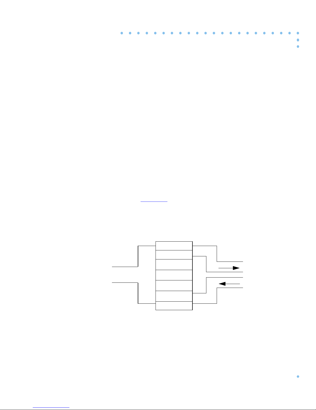
T1 was developed to multiple x 24 analog lines. A T1 digital transmission
system takes in 24 analog signals, conv erts each analog signal to a digital
signal, and multiplexes those 24 digital signals onto a 4-wire digital T1
line. What once required 24 2-wire pairs, now requires only two 2-wire
pairs (refer to
Figure 1-1).
Chapter 1
Introduction
Channel
Bank
Channel
24 Analog Lines
Figure 1-1. T1 Wiring Scheme
Bank
1
2
3
.
.
.
24
4-Wire
Digital T1
Line
1-1T1 Getting Started Guide
Page 16
Chapter 1 Introduction
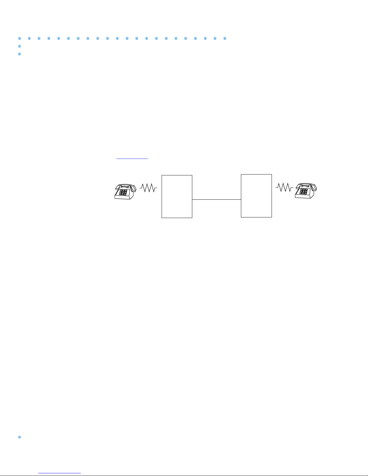
A T1 digital transmission system typically consists of two T1 terminal
devices such as channel banks connected by a T1 line. The channel bank
receives signals from up to 24 analog channels; converts each analog
signal to a digital signal; multiplexes the digital signal onto a single 4wire digital T1 line which carries the T1 signal to the other end of the
circuit. At the far end, another channel bank demultiplexes the signal;
and conv erts each of the 24 digital signals back into analog signals (refer
Figure 1-2).
to
Channel
T1 Line
Bank
1 to 24
Analog
Channels
Figure 1-2. Typical T1 Transmission System
Channel
Bank
1 to 24
Analog
Channels
All of the multiplexing and demultiplexing is done at a rate of
1.544 Mbps. The individual DS0 channels operate at 64 kbps. All DS0
channels in a T1 channel bank are treated equally.
1-2
T1 Getting Started Guide
Page 17
The Remote Annex 6100
The Remote Annex 6100 is a T1 Remote Access server. The Remote
Annex 6100 has a T1 engine that, like a channel bank, receives and
transmits data and signaling information from 24 channels
simultaneously.
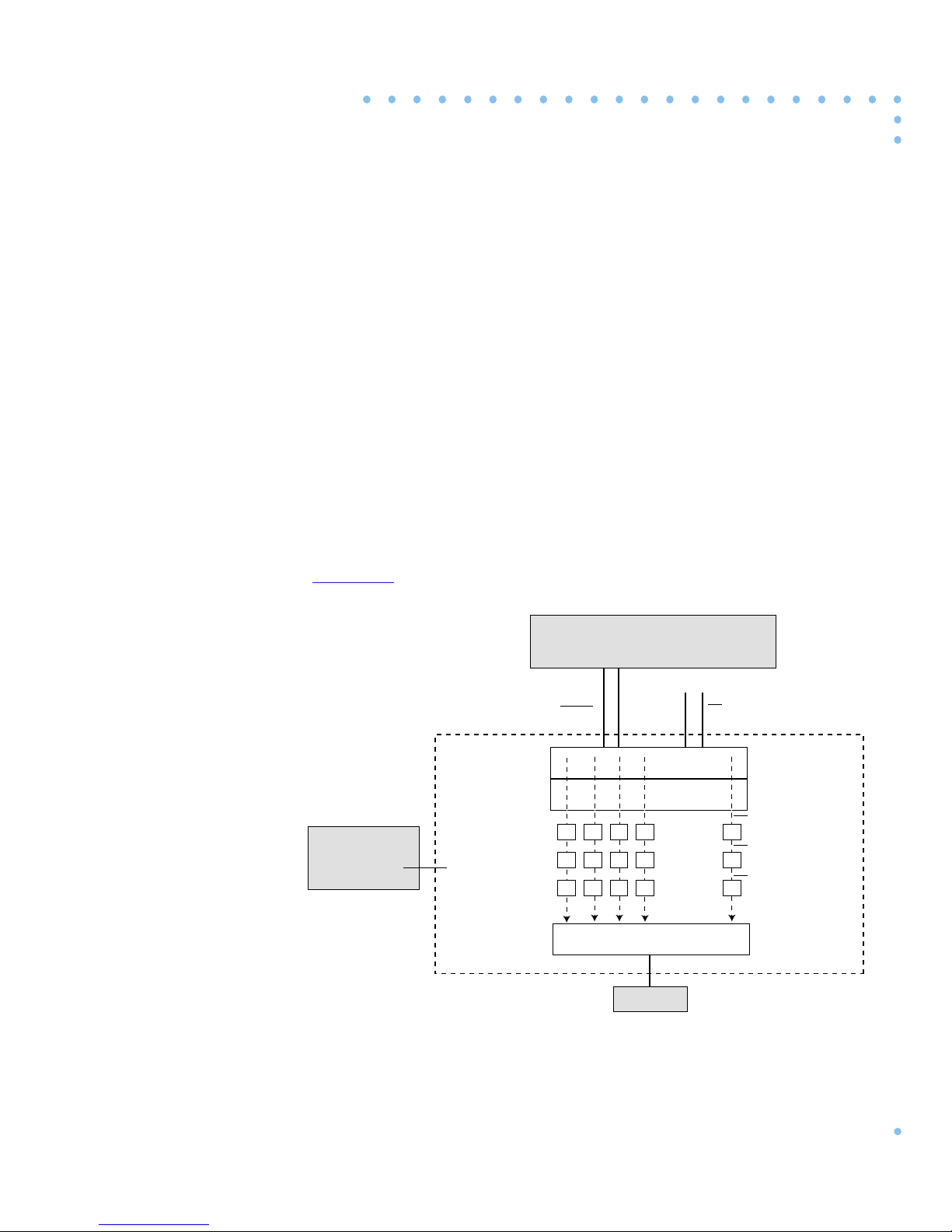
In the receive direction, data is sent to the T1 engine as a digital T1 signal.
The T1 engine passes the data stream to the multiplexor where it is
demultiplexed and passed to 24 separate DS0 channels. Each DS0
channel has its own coder/decoder (codec) that con verts the digital PCM
(Pulse Code Modulation) data stream into an analog data stream. The
analog data stream is then passed to an internal modem where it is
converted to a digital serial data stream and passed to a serial port.
Figure 1-3 shows an example of the data flow in the receive direction.
Chapter 1 Introduction
Service Provider
T1 Network Interface
Digital PCM Data Channelized
T1 Engine
Multiplexor
c
c
c
m
m
2
3
Standard Remote Annex
Remote Annex
6100
CODECs
Modems (Internal)
Serial Ports
m
1
Figure 1-3. Data Flow in the Receive Direction
c
m
4
LAN
• • •
T1 Drop and
Insert Interface
Digital PCM Data
c
Analog Data
m
Digital Serial Data
24
T1 Getting Started Guide
1-3
Page 18
Chapter 1 Introduction
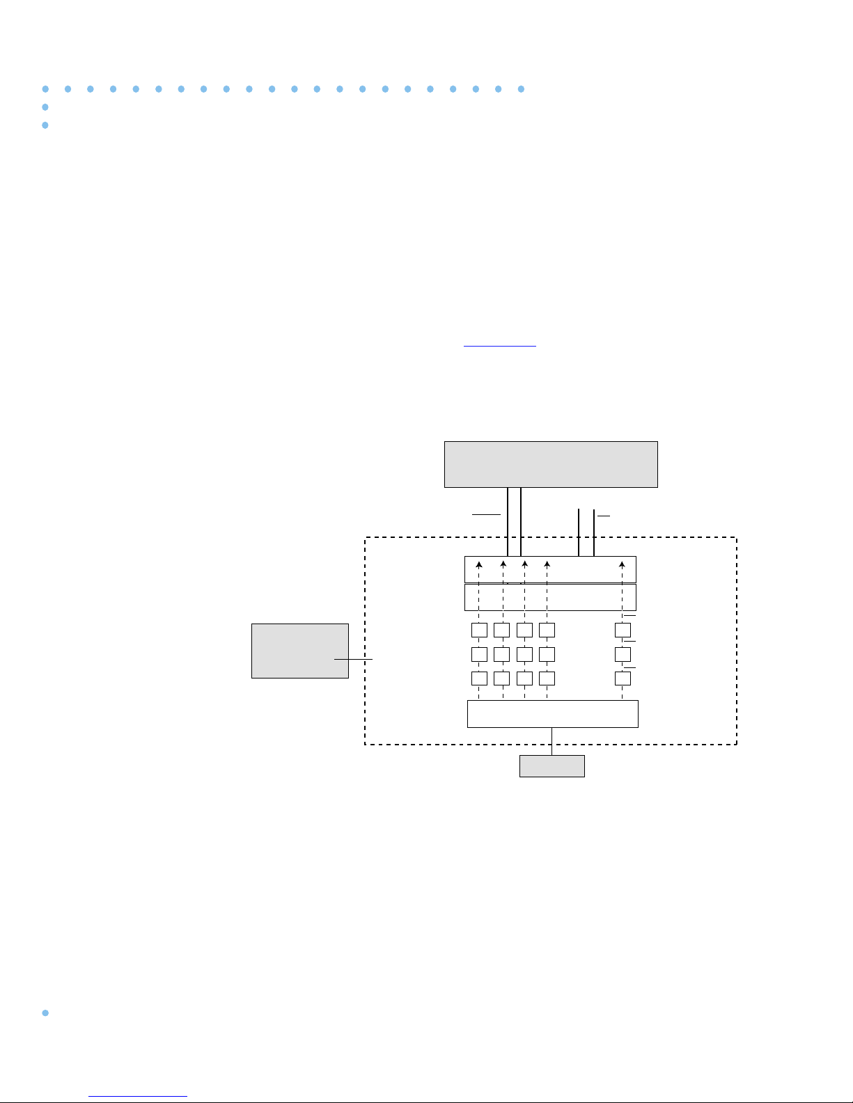
In the transmit direction, the serial ports pass digital serial data to the
modem. The modem converts the data streams to analog data streams and
passes them to a codec. The codec converts the analog data stream into
digital PCM data streams and passes them to the multiplexor. The
multiplexor combines the signals into a single T1 signal and passes it to
the T1 engine. The T1 engine sends the signal to the T1 Network Interface
which passes it to the T1 line.
Figure 1-4 shows an example of the data
flow in the transmit direction.
Service Provider
T1 Network Interface
Digital PCM Data Channelized
T1 Engine
Multiplexor
c
c
c
m
m
2
3
Standard Remote Annex
Remote Annex
6100
CODECs
Modems (Internal)
Serial Ports
m
1
Figure 1-4. Data Flow in the Transmit Direction
c
m
4
LAN
• • •
T1 Drop and
Insert Interface
Digital PCM Data
c
Analog Data
m
Digital Serial Data
24
1-4
T1 Getting Started Guide
Page 19
Chapter 1 Introduction
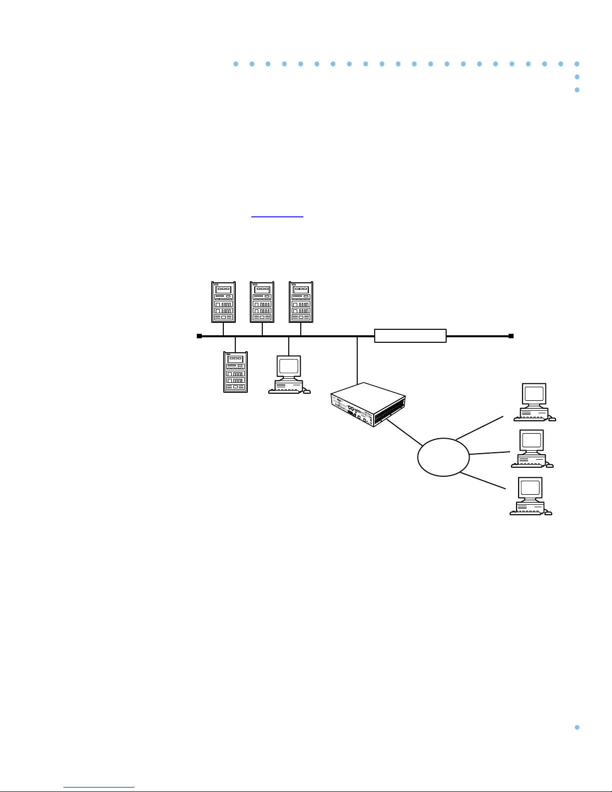
The Remote Annex has a maximum of 24 internal modems. The internal
modems are high performance, error-correcting V.34 modems. Refer to
Chapter 4 The Internal Modems for a description of the features that the
modems support. The modems are used for dial-in and dial-out access to
the LAN.
Figure 1-5 illustrates an example of dial-in sessions.
DEC
Novell
Server
IBM UNIX
Apple
Macintosh
Corporate LAN
Remote
Annex 6100
T1
Digital Line
Central
Office
Up to 24
Analog Lines
Figure 1-5. Remote Access with the Remote Annex 6100
Ethernet
T1 Getting Started Guide
1-5
Page 20

Chapter 1 Introduction
The Remote Annex comes with software that provides network access to
the following networks:
• Novell Netware (IPX)
• UNIX (TCP/IP)
• Macintosh (AppleTalk)
Refer to the Remoe Annex Administrator’s Guide for UNIX for a
description of the supported software features.
In addition to the standard software package, the Remote Annex software
distribution includes a number of T1 commands and parameters that are
used for configuration and administration (see Chapter 2).
1-6
T1 Getting Started Guide
Page 21

T1 Commands
Chapter 2
Commands and Parameters
This chapter contains a description of the T1 software commands and
parameters.
The Remote Annex comes with software that supports T1-specific
commands and parameters for configuring and administering the device.
The following sections describe those commands and parameters.
The Remote Annex software comes with the following ne w or enhanced
commands:
Table 2-1. T1-Related Commands
Command Command Type Description
stats -T CLI Displays T1 Network Interface
statistics.
t1_loopback Superuser CLI Places the T1 engine into
loopback mode.
reset Superuser admin/na/
snmp
set Superuser admin/na/
snmp
show admin/na/snmp Shows a T1 configuration
These commands are described in more detail in the sections that follow .
Resets the T1 engine, ESF
statistics, and internal modems.
Sets a T1 configuration
parameter.
parameter.
2-1T1 Getting Started Guide
Page 22

Chapter 2 Commands and Parameters
stats -T
The stats -T command displays T1 network interface statistics for the
Annex.
stats -T [ current | total | all | interval_set | clear_alarm ]
Table 2-2. Arguments for the stats -T Command
Argument Description
current Displays T1 statistics information for the current
total Displays a summary of T1 statistics information for the
all Displays the T1 statistics for each one of the valid
Table 2-2 describes the arguments for stats -T. The syntax is:
15-minute interval.
last 24 hours.
intervals. There are up to 96 intervals (15 minutes per
interval) for a 24-hour period.
interval _set Displays the T1 statistics for the selected intervals only.
You can enter a single interval or a range of intervals from
1 to 96. Interval 1 is the most recent interval. For example:
stats -T 4-6, 10 displays intervals 4, 5, 6, and 10.
clear_alarm Clears the alarm condition saved in the history buffer.
Once the alarm history buffer is cleared, the next alarm
event is captured and stored in the history buffer.
Subsequent alarm events will not overwrite the history
buffer. This option is available only to the Superuser.
All T1 statistics are captured in 15-minute periods. Information on
intervals being captured are kept in “current. ” Once the 15-minute interval
expires, the information in “current” is transferred to interval #1, and the
current statistics are cleared before restarting the statistics capture
process. All intervals are aged ev ery 15 minutes. Intervaln becomes n+1,
and interval 96 is discarded. The 96 intervals cover a 24-hour period.
Interval #1 becomes valid only after the T1 engine has been on-line for
at least 15 minutes.
2-2
T1 Getting Started Guide
Page 23

Chapter 2 Commands and Parameters
The stats -T current command display looks like this:
annex# stats -T current
alarm history: [ no blue no red no yellow ], Fri July 28 16:48:37
1995 EDT
Alarms: no blue no red no yellow
engine:offline no sync no D&I sync no loss of signal
serial number: 0811
circuit ID:
T1 info:
unit ID: XYLOGICS T1-ENGINE 085234 Rev. A 07/19/95 6343
loopback mode: No loopback uptime: 69:07:49
Current Statistics
number of valid seconds: 469
bursty errored seconds (ESF only):0Controlled slip seconds:0
errored seconds: 0 Severly errored seconds:0
unavailable seconds: 0
out of frame errors: 0 bipolar violations: 0
CRC errors (ESF only): 0 controlled slips: 0
received net alarms: 0
annex#
The information displayed from a stats -T command is described in
Table 2-3.
T1 Getting Started Guide
2-3
Page 24

Chapter 2 Commands and Parameters
Table 2-3. The stats -T Command Display
Field Description
Sync When Sync is true, the T1 engine is detecting frame
Loss of Signal When Loss of Signal is true, the T1 engine is not detecting
Blue Alarm When the Blue Alarm is true, the T1 engine is receiving
synchronization. When Sync is false. the T1 engine has
lost frame synchronization and enters the Red Alarm state.
pulses on the T1 network interface receiver. When Loss of
Signal is false, the T1 network interface is receiving
pulses. The loss of signal condition causes the T1 engine
to transmit AIS (all ones unframed) on the T1 network
interface.
AIS (all ones unframed) from the network. When the Blue
Alarm is false, the T1 engine is not receiving AIS. The
Blue Alarm event saved in the history buffer is also
displayed.
Red Alarm When the Red Alarm is true, the T1 engine has detected
loss of frame synchronization. During this condition, the
T1 interface is sending a Yellow Alarm to the network.
When the Red Alarm is false, The T1 engine is in frame
synchronization and the sync indication is true. The Red
Alarm event saved in the history buffer is also displayed.
Yellow Alarm When the Yellow Alarm is true, the T1 engine is receiving
a Yellow Alarm from the network. When the Yellow
Alarm is false, the T1 engine is not receiving a Yellow
Alarm from the network. The Yellow Alarm event saved
in the history buffer is also displayed.
(continued on next page)
2-4
T1 Getting Started Guide
Page 25

Chapter 2 Commands and Parameters
Table 2-3. The stats -T Command Display (Continued)
Field Description
Loopback The loopback status has the following possible states:
None - There is no loopback in progress. The test LED
on the front panel is not illuminated.
Local - The T1 network interface is in local loopback.
The test LED on the front panel is illuminated.
Line - The T1 network interface is in line loopback. The
test LED on the front panel is illuminated.
Payload - This means that the T1 network interface is in
payload loopback. The test LED on the front panel is
illuminated.
Online When illuminated, the T1 engine is engaged with the
network. Otherwise, the T1 Network Interface and Drop/
Insert Interface are isolated from the T1 engine.
Up Time Amount of time the T1 engine has been up, in hours,
minutes, and seconds. The “hours” field is a 16-bit
register that can count up to 2700 days (more than 7
years).
Serial Number The T1 engine’s serial number.
Circuit ID The T1 engine’s Circuit ID displayed from the
tni_circuit_id parameter.
Unit ID The T1 engine’s Unit ID displayed as:
“XYLOGICS T1-ENGINE 085nnn Rev. n mm/dd/yy xxxx”
Where:
085nnn - This is the firmware number.
Rev. n - This is the firmware revision number.
mm/dd/yy - This is the firmware release date.
xxxx - This is the EPROM check sum.
(continued on next page)
T1 Getting Started Guide
2-5
Page 26

Chapter 2 Commands and Parameters
Table 2-3. The stats -T Command Display (Continued)
Field Description
DII Sync When DII Sync is true, the Drop/Insert Interface is
Interval The 15-minute interval being displayed. This is an inte ger
receiving ones pulses and is in frame sync. When DII
Sync is false, the Drop/Insert Interface is out of frame
sync or not receiving pulses and is sending AIS (all ones
unframed).
from 1 to 96, “current” or “total.”
Number of
Valid Seconds
Number of
15-minute
Periods
Bursty Errored
Seconds
Controlled Slip
Seconds
Errored
Seconds
Severely
Errored
Part of the “current” report which indicates the number of
seconds for which the statistics data has been collected.
Part of the “total” report which indicates the number of
valid 15-minute periods. This could also be derived from
the uptime.
A Bursty Errored Second (BES) is a second with more
than one, but less than 320 CRC error events.
A Controlled Slip Second (CSS) is a second with one or more
Controlled Slips.
An Errored Second is a second with one or more ESF error events;
that is, one or more CRC error events or one or more Out of
Frames (OOFs).
A Severely Errored Second (SES) is a second with 320 or more
CRC error events or one or more OOFs.
Seconds
Unavailable
Seconds
(continued on next page)
Unavailable Seconds (UAS) are a count of 1-second intervals
during which service is unavailable.
2-6
T1 Getting Started Guide
Page 27

Chapter 2 Commands and Parameters
Table 2-3. The stats -T Command Display (Continued)
Field Description
Out of Frame
Errors
An Out of Frame (OOF) event begins when any two of
four consecutive frame synchronizing bits are received
from the network interface. An OOF state ends when
reframe occurs.
BiPolar
Violations
A BiPolar Violation (BPV) error event for an
AMI-coded signal is the occurrence of a pulse of the
same polarity as the previous pulse. A BPV error event
for a B8ZS--coded signal is the occurrence of a pulse of
the same polarity as the previous pulse without being a
part of the zero substitution code.
CRC Errors A CRC error occurs when the CRC field calculated by the
customer installation, based on the incoming DS1 signal
does not agree with the CRC field contained in the DS1
signal received from the network.
Controlled Slips A Controlled Slip is the occurrence of a replication or
deletion of a DS1 frame by the receiving terminal.
Receive
The number of seconds with alarm events.
Network Alarm
Seconds
T1 Getting Started Guide
2-7
Page 28
Chapter 2 Commands and Parameters
t1_loopback
The Superuser t1_loopback command places the T1 engine into
loopback mode. None of the loopback conditions persist through a power
down or reboot. A major consideration to those using the T1 service must
be made before using this command since it will completely disrupt the
T1 service. The syntax for the t1_loopback command is:
t1_loopback [ none | line | payload | local]
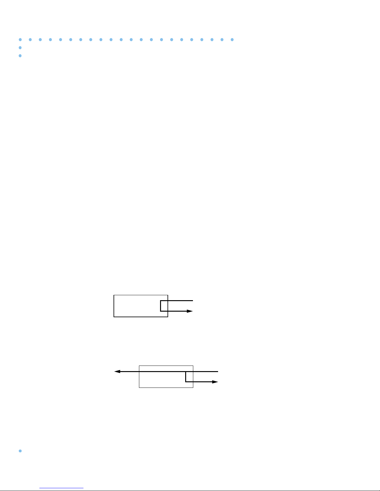
The following paragraphs contain a description of the arguments used
with the t1_loopback command.
None
Line
Payload
No loopback. This is the default. If the T1_loopback command is initiated
with no parameters, then none is assumed. It cancels any user specified
loopbacks.
Line loopback provides the network a means to test the T1 circuit for
single ended fault isolation. The line loopback regenerates the DS1 signal
and does not correct bipolar violations.
DTE
T1
Network
Payload loopback is used to provide a loopback tow ard the network. The
data portion of the DS0s is looped back.
DTE
T1
Network
2-8
T1 Getting Started Guide
Page 29
Chapter 2 Commands and Parameters
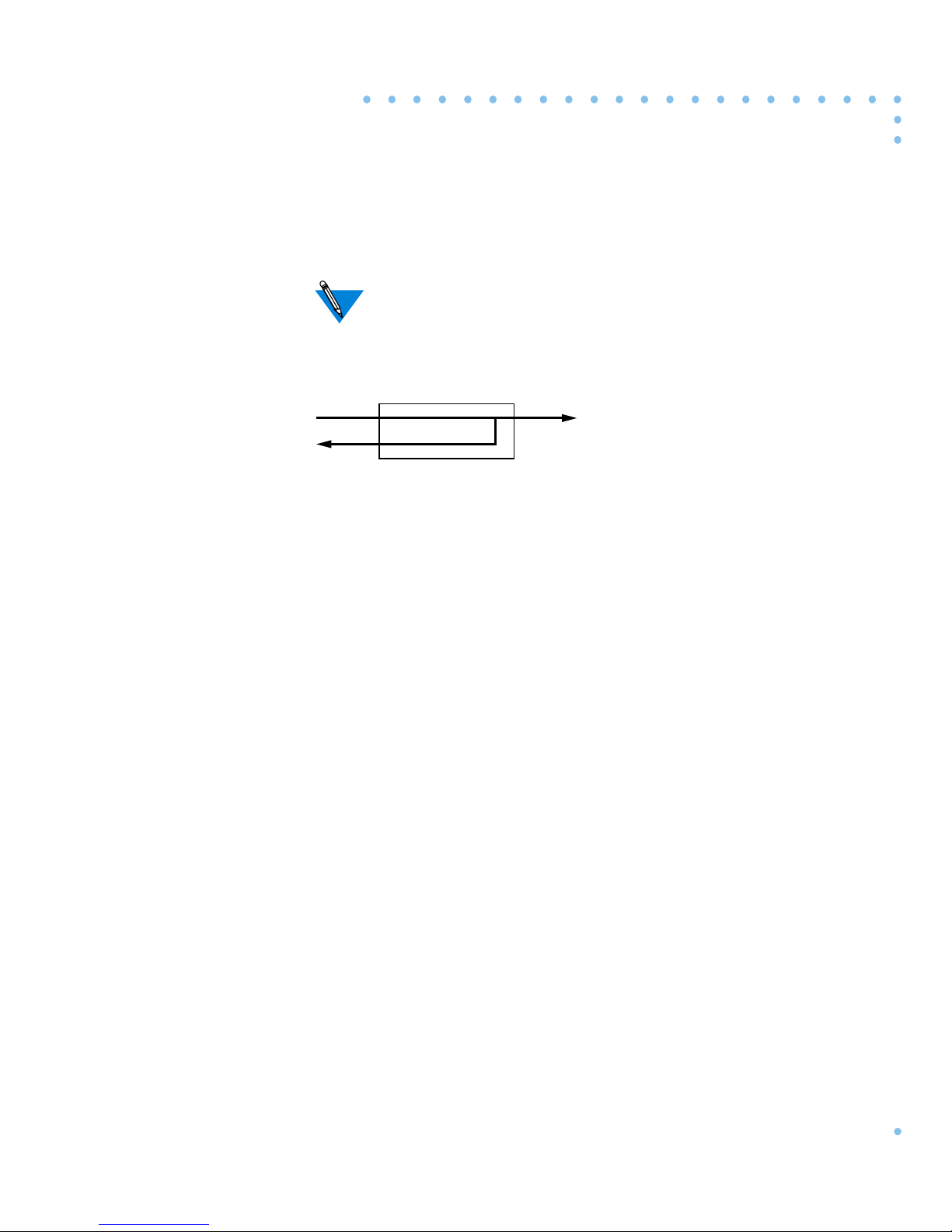
Local Local loopback will loopback the data from the customer side of both the T1
Network Interface and the T1 Drop/Insert Interface.
Network direction loopbacks in most cases can be initiated by the
service provider. The front panel Test indicator illuminates when
the T1 is in loopback.
DTE
T1
Network
T1 Getting Started Guide
2-9
Page 30
Chapter 2 Commands and Parameters
reset
The reset t1 command resets the T1 engine and the T1 statistics
information. This command is used to change the T1 engine’s parameter
configuration. The T1 soft, hard, and esf keywords are described in
Table 2-4. The syntax is:
reset t1 [soft | hard | esf]
Table 2-4. Keywords for the reset t1 Command
The reset command (available from na or admin) requires
Superuser privileges. A reset terminates any active connections.
Keyword Definition
soft This setting reconfigures the software parameters and will
only disrupt the service on the DS0 channels that are
changed.
hard This setting resets the T1 engine causing the T1 Drop/
Insert interface and modem sessions to terminate.
If modem sessions and/or equipment are
attached to the Drop and Insert Interface, their
service will be interrupted for a short period of
time (usually a few seconds).
esf This setting resets all the statistics in the T1 engine.
2-10
T1 Getting Started Guide
Page 31

Chapter 2 Commands and Parameters
The reset int_modem command resets the specified T1 modem_set.
There is no physical reset button. A modem reset forces the port to be
reset. In addition, if the signal protocol is set to wink start or immediate
start, a special AT command is sent to the modem to select the dialtone
detection mechanism.
The modem_set parameter specifies the individual modem numbers,
separated by commas, or a range of numbers separated by a hyphen. The
valid modem number range is 1 to 24, inclusive.
The syntax is:
reset int_modem <modem_set>
T1 Getting Started Guide
2-11
Page 32

Chapter 2 Commands and Parameters
set t1
The set t1 command modifies Remote Annex configuration parameters.
The syntax is:
set t1 t1_parameters
Refer to T1 Parameters on page 2-14 for a list and description of the
keywords that can be used with this command.
The set t1 command (available from na or admin) requires
Superuser privileges.
2-12
T1 Getting Started Guide
Page 33

Chapter 2 Commands and Parameters
show t1
Theshow t1command (available from na or admin) displays current T1
configuration parameters.
The syntax is:
show t1 t1_parameter
Refer to T1 Parameters on page 2-14 for a list and description of the
keywords that can be used with this command.
T1 Getting Started Guide
2-13
Page 34

Chapter 2 Commands and Parameters
T1 Parameters
The Remote Annex software comes with the following new T1
parameters:
• alarmsyslog
• bypass
• map
• ring
• sigproto
• switch_type
• t1_info
• tdi_distance
• tdi_framing
• tdi_line_code
• tni_circuit_id
• tni_clock
• tni_esf_fdl
• tni_framing
• tni_line_buildout
• tni_line_code
• tni_ones_density
The following paragraphs contain a description of the T1 parameters.
2-14
T1 Getting Started Guide
Page 35

Chapter 2 Commands and Parameters
alarmsyslog
This T1 parameter enables or disables the T1 alarm event syslogs. A Y
enables alarm syslogs, an N disables it. The default is Y.
The command display looks like this:
admin: set t1 alarmsyslog no
admin: show t1 alarmsyslog
alarmsyslog: no
admin:
T1 Getting Started Guide
2-15
Page 36

Chapter 2 Commands and Parameters
bypass
This T1 parameter is used to remove the T1 engine from the network.
When bypass is set to Y, the T1 engine is off-line and the T1 Network
Interface (T1NI) and the T1 Drop and Insert Interface (T1DII) are
physically isolated from the T1 engine. When bypass is set to Y, the T1
engine has no effect on the T1 circuit. When bypass is set to N, the T1
engine is attached to both the T1NI and the T1DII. The default is Y.
The command display looks like this:
admin: set t1 bypass yes
admin: show t1 bypass
bypass: yes
admin:
2-16
T1 Getting Started Guide
Page 37
Chapter 2 Commands and Parameters
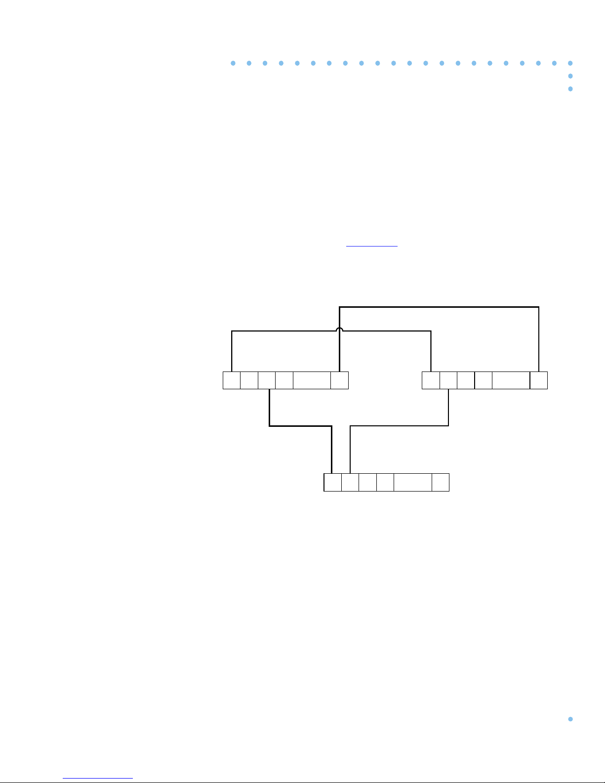
map
This T1 parameter controls the mapping of the modems to the T1 Drop
and Insert Interface (T1DII) and the T1 Network Interface (T1NI) DS0
channels. The modems can be mapped to any unoccupied slot on either
interface. The interfaces can be mapped to each other on channels that
are not occupied by modems.
and modem mapping.
set t1 ds0=1 map voice
Figure 2-1 shows an example of interface
set t1 ds0=24 map data
DSI Interface
Modems
...
24
1234
1234
...
1234
set t1 ds0=3 map ds1_modem 1 set t1 ds0=2 map di_modem 2
DI Interface
24
Figure 2-1. DS0 Mapping
...
24
PBXT1
T1 Getting Started Guide
2-17
Page 38

Chapter 2 Commands and Parameters
The map command is used in two ways:
• Mapping a modem to an interface.
• Mapping the two interfaces.
Mapping a Modem to an Interface
The syntax for mapping a modem to an interface is as follows:
set t1 ds0=<
Table 2-5. Options for Mapping a Modem to an Interface
Option Description
channel_number
> map <
map_val
> <
modem_number
channel number A T1 Network Interface or Drop/Insert Interface
channel number from 1 to 24.
map_val The map_val option defines the interface as:
ds1_modem for the T1 Network Interface.
di_modem for the Drop/Insert Interface.
modem_number This option must be specified. Themodem_number
value is a number from 1 to 24.
>
2-18
T1 Getting Started Guide
Page 39
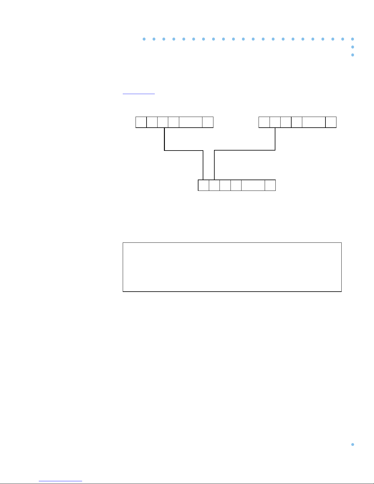
Figure 2-2 illustrates this mapping.
Chapter 2 Commands and Parameters
DSI Interface
Modems
...
24
1234
1234
...
1234
set t1 ds0=3 map ds1_modem 1 set t1 ds0=2 map di_modem 2
DI Interface
24
Figure 2-2. Mapping a Modem to an Interface
The command display for the previous example looks like this:
admin: show t1 ds0=2,3 map
ds0:2 di modem 2
ds0:3 ds1 modem 1
admin:
...
24
PBXT1
T1 Getting Started Guide
2-19
Page 40

Chapter 2 Commands and Parameters
Mapping the Two Interfaces
The syntax for mapping the two interfaces is as follows:
set t1 ds0=<
Table 2-6. Options for Mapping the Two Interfaces
Option Description
channel_set
> map <
map_val
>
channel_set A set of DS0 channels that includes a range from 1
to 24 and hyphenated ranges.
map_val The map_val option can be:
• unused
• voice - maps the DS0 channel to the DI
interface (voice).
• data - maps the DS0 channel to the DI
interface (data).
Setting ads0 to unused makes it look busy to remote callers. This setting
is useful when a modem malfunctions and needs to be replaced.
2-20
T1 Getting Started Guide
Page 41
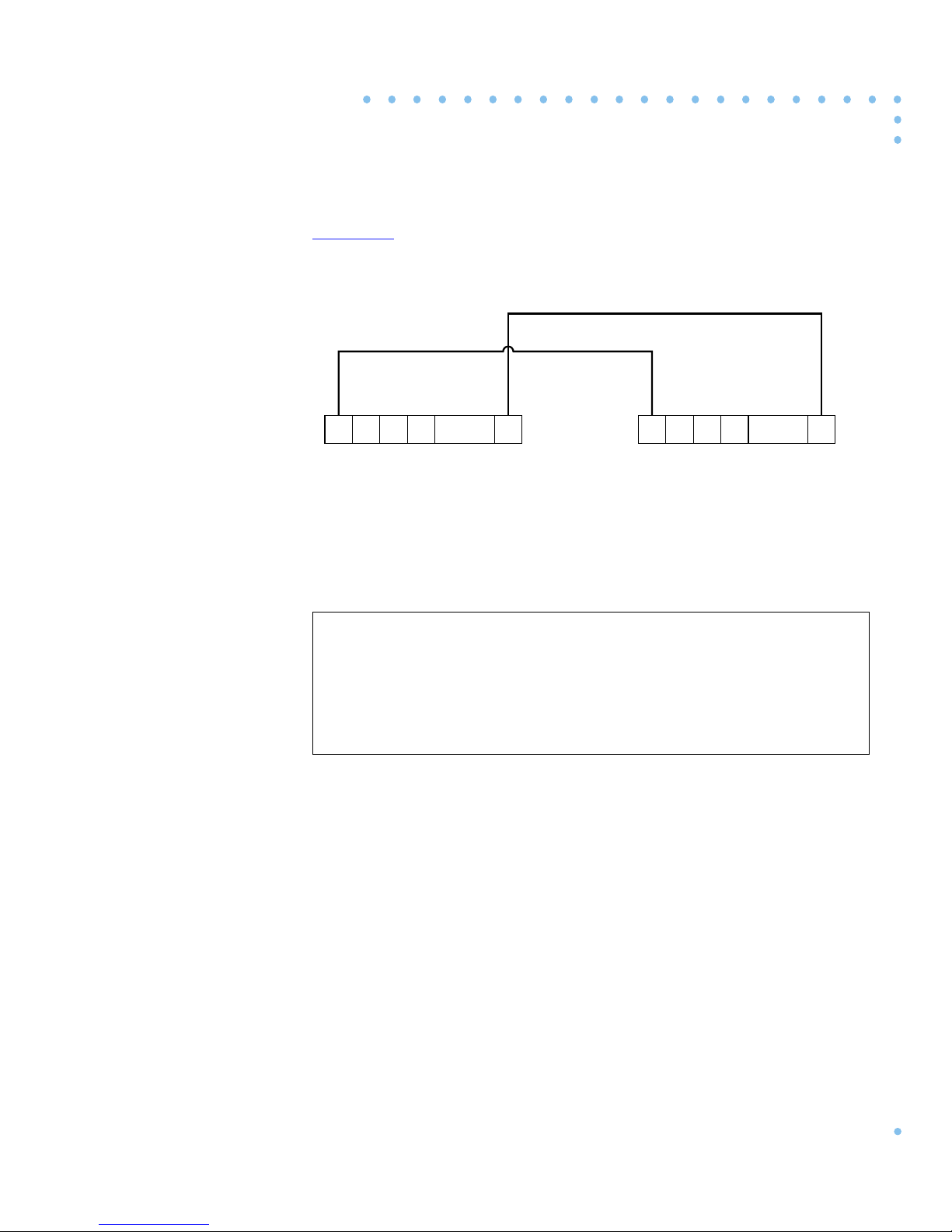
Figure 2-3 illustrates this mapping.
set t1 ds0=1 map voice
Chapter 2 Commands and Parameters
set t1 ds0=24 map data
DSI Interface
1234
...
24
Figure 2-3. Mapping the Two Interfaces
The command display looks like this:
admin: show t1 ds0=1,4,24 map
ds0:1 voice
ds0:4 unused
ds0:24 data
admin:
DI Interface
1234
...
24
PBXT1
T1 Getting Started Guide
2-21
Page 42

Chapter 2 Commands and Parameters
ring
This T1 parameter is used to provide the audible ring to the central office
for incoming calls. The default is Y, and the audible ring is sent to the
central office. This parameter is used with wink_start and
immediate_start protocols only. The syntax for this command is:
set t1 ds0=<
channel_set
> ring [
yes
|no]
The channel_set option represents a set of DS0 channels from 1 to 24.
The command display looks like this:
admin: show t1 ring
ds0: 1 yes
ds0: 2 no
.
.
.
ds0: 24 yes
admin:
2-22
T1 Getting Started Guide
Page 43

Chapter 2 Commands and Parameters
sigproto
This T1 parameter is used to specify the inbound and outbound signaling
protocols supported by each T1 channel (DS0). Each channel supports
an inbound protocol and an outbound protocol. Both protocols must be
specified even if they are the same. If the protocol pair is invalid, it is
rejected with an error message. For inbound-only channels, the outbound
protocol must be set to none. For outbound-only channels the inbound
protocol must be set to none. The syntax for this command is:
set t1 ds0=<channel_set > sigproto <proto_in> <proto_out>
Table 2-7. Options for the sigproto command
Option Description
channel_set A set of DS0 channels that includes a range from 1
to 24 and hyphenated ranges.
proto_in The proto_in option defines an inbound signaling
protocol. The signaling protocols are:
• loop_start - Bidirectional (default)
• ground_start - Bidirectional
• wink_start - Inbound, outbound, or
bidirectional
• immediate_start - Inbound, outbound
• None
proto_out The proto_out option defines an outbound
signaling protocol. The protocols are described
above.
T1 Getting Started Guide
2-23
Page 44

Chapter 2 Commands and Parameters
The command display looks like this:
admin: set t1 ds0=3,8 sigproto immediate_start none
admin: show t1 sigproto
ds0: 1 in: loop_start
out: loop_start
ds0: 2 in: wink_start
out: wink_start
ds0: 3 in: immediate_start
out: none
ds0: 8 in: immediate_start
out: none
.
2-24
T1 Getting Started Guide
Page 45
Chapter 2 Commands and Parameters
switch_type
This parameter can be configured to support standard Channelized T1,
Hong Kong Channelized T1, and a 1AESS switch running Channelized
T1.
Standard Channelized T1 is the default configuration for this parameter .
When configured for Hong Kong, it reconfigures the modem’s output
levels (low frequency component to -10dBm0 and high frequency
component to -6dBm0) and will reprogram the ring cadence to 300ms
on, 400ms off, 300ms on, and 3s off.
When configured for 1AESS switch, it sends 00 instead of 11 through
the AB bits to signal busy when configured for Ground Start.
The following command display shows ho w to configure the switch_type
parameter for Hong Kong Channelized T1:
admin: set t1 switch_type hk
admin:
After the set T1 switch_type hk command is issued, you must
change the type_of_modem field to BAYT1_HK_288 in the
modem section of the Annex confiuration file. You must also set the
type_of_modem port parameter to BAYT1_HK_288. See the
Remote Annex Administrator’s Guide for UNIX for more
information.
T1 Getting Started Guide
2-25
Page 46

Chapter 2 Commands and Parameters
t1_info
This T1 parameter stores installation information from the service
provider , such as a telephone number to call should the network go down.
This parameter is limited to a 120-byte string of printable ASCII
characters. The command display looks like this:
admin: set t1 t1_info “Example: If the network goes down,call x555”
admin: show t1 t1_info
t1_info: “Example: If the network goes down, call x555”
admin:
2-26
T1 Getting Started Guide
Page 47

Chapter 2 Commands and Parameters
tdi_distance
This T1 parameter defines the distance, in feet, of the cable that runs from
the T1DII to the Private Branch Exchange (PBX) or other equipment.
The parameter setting is an integer from 0 to 655. The default setting is
0. The command display looks like this:
admin: set t1 tdi_distance 200
admin: show t1 tdi_distance
tdi_distance: 200
admin:
T1 Getting Started Guide
2-27
Page 48

Chapter 2 Commands and Parameters
tdi_framing
This T1 parameter controls which super frame format is used on the T1
Drop/Insert Interface. The parameter settings are d4 (super frame) and
esf (extended super frame). The default setting is esf. The value for
tdi_framing may or may not be the same astni_framing. The command
display looks like this:
admin: set t1 tdi_framing esf
admin: show t1 tdi_framing
tdi_framing: esf
admin:
2-28
T1 Getting Started Guide
Page 49

Chapter 2 Commands and Parameters
tdi_line_code
This T1 parameter selects the line code to be used on the T1 Drop/Insert
Interface (T1DII). The device connected to the T1DII determines which
line code to use. The parameter settings are ami and b8zs. The default
setting is b8zs. The command display looks like this:
admin: set t1 tdi_line_code b8zs
admin: show t1 tdi_line_code
tdi_line_code:b8zs
admin:
T1 Getting Started Guide
2-29
Page 50

Chapter 2 Commands and Parameters
”
tni_circuit_id
This T1 parameter stores the T1 Circuit Identifier String. The T1 Circuit
Identifier String comes from the service provider and is used for customer
service calls. The parameter setting is a string of up to
120 characters. The default setting is the null string. The command
display looks like this:
admin: set t1 tni_circuit_id “this is a sample circuit ID
admin: show t1 tni_circuit_id
tni_circuit_id: “this is a sample circuit ID”
admin:
2-30
T1 Getting Started Guide
Page 51

Chapter 2 Commands and Parameters
tni_clock
This T1 parameter sets the clock for the T1 Network Interface. Parameter
settings include loop (service provider), local (Annex), external (T1
Drop/Insert Interface). The default setting isloop. The command display
looks like this:
admin: set t1 tni_clock loop
admin: show t1 tni_clock
tni_clock: loop
admin:
T1 Getting Started Guide
2-31
Page 52

Chapter 2 Commands and Parameters
tni_esf_fdl
This T1 parameter sets the T1 Facilities Data Link (FDL) format. The
FDL format is used in conjunction with the ESF format and is determined
by the service provider. The parameter settings include ANSI (ANSI
T1.403) and A T&T (AT&T TR54016) standard formats. The command
display looks like this:
admin: set t1 tni_esf_fdl att
admin: show t1 tni_esf_fdl
tni_esf_fdl: att
admin:
2-32
T1 Getting Started Guide
Page 53

Chapter 2 Commands and Parameters
tni_framing
This T1 parameter controls which super frame format is used on the
T1 Network Interface. Parameter settings include d4 (super frame) and
esf (extended super frame). The default setting is esf. The value for
tni_framingmay or may not be the same as tdi_framing. The command
display looks like this:
admin: set t1 tni_framing esf
admin: show t1 tni_framing
tni_framing: esf
admin:
T1 Getting Started Guide
2-33
Page 54

Chapter 2 Commands and Parameters
tni_line_buildout
This T1 parameter sets the Line Build-Out (LBO) value. The Channel
Service Unit (CSU) portion of the T1 Network Interface requires the
administrator to configure a LBO value. The service provider will supply
a value measured in decibels (dB) based on the amount of cable loss from
the service provider’s location to the Annex. Parameter settings include
0,7.5, 15, and 22.5. The default is0. The command display looks like this:
admin: set t1 tni_line_buildout 7.5
admin: show t1 tni_line_buildout
tni_line_buildout: 7.5
admin:
2-34
T1 Getting Started Guide
Page 55

Chapter 2 Commands and Parameters
tni_line_code
This T1 parameter selects the line code for the T1 Network Interface. The
service provider determines the line code setting. Parameter settings
includeami and b8Zs. The default setting is b8zs. The command display
looks like this:
admin: set t1 tni_line_code b8zs
admin: show t1 tni_line_code
tni_line_code: b8zs
admin:
T1 Getting Started Guide
2-35
Page 56

Chapter 2 Commands and Parameters
tni_ones_density
This T1 parameter is used to defeat the Annex’s ones density monitor.
The Annex T1 engine has a built in ones density monitor that will provide
the network with the correct number of one pulses. The ones density
monitor does the following:
1. The monitor does not allow the Annex to transmit more than15
2. The monitor ensures that the Annex has at least
This parameter has an on and an off setting. This parameter should be set
to on when using AMI coding. The default is off. The command display
looks like this:
consecutive zeros.
time window of 8X(
N
+1) bits, where N=1 to 23.
N
ones in every
admin: set t1 tni_ones_density off
admin: show t1 tni_ones_density
tni_ones_density: off
admin:
2-36
T1 Getting Started Guide
Page 57

Chapter 2 Commands and Parameters
T1-Specific Parameters vs. MIB Objects
Table 2-8 lists the T1-specific parameters and their corresponding MIB
object names.
of the Simple Network Management Protocol (SNMP).
The following string precedes the MIB object names:
“.iso.org.dod.internet.private.enterprises.xylogics.annex.”.
Table 2-8. T1- Specific Parameters vs. MIB Objects
T1 Parameter MIB Object Name
alarmsyslog anxt1AlarmSyslog
bypass anxt1EngineBypass
Refer to the Annex Network Administrator’s Guide for a description
map anxt1ChanMap
ring anxt1ChanRing
sigproto anxt1ChanSigProto
t1_info anxt1Info
tdi_distance anxt1DiiDistance
tdi_framing anxt1DiiFraming
tdi_line_code anxt1DiiLineCode
tni_line_buildout anxt1Ds1LineBuildout
tni_ones_density anxt1Ds1OnesDensity
T1 Getting Started Guide
2-37
Page 58

Chapter 2 Commands and Parameters
2-38
T1 Getting Started Guide
Page 59

This chapter contains a description of the steps you need to take to
set up your Remote Annex and T1 connection.
Refer to the Remote Annex 6100 Hardware Installation Guide or the
Remote Annex 5391/CT1 Hardware Installation Guide for information
about installing the hardware. Refer to theRemote Annex Administrator’s
Guide for UNIX for configuration information.
Configuring a T1 Connection
The following information will help you configure your T1 connection
and bring your Remote Annex on-line. Proceed as follows:
Chapter 3
Configuration
1. Obtain the following information:
• IP address
• Subnet mask
• IP address of load host
• IP address of dump host
• Broadcast address
• T1 framing
• T1 line code
• T1 signaling
Your System Administrator and Service Provider should have the
information described in Step 1.
3-1T1 Getting Started Guide
Page 60

Chapter 3 Configuration
2. Be sure that a 9600-baud terminal is attached to the console
port (Remote Annex 6100) or the service port (Remote Annex
5391/CT1).
3. Power up the Remote Annex. Press the Setup button (Remote
Annex 6100 only).
Make sure the Setup light is On (Remote Annex 6100 only). The
power-up diagnostics will run and the Monitor prompt will display on
the console or the service port terminal when the diagnostics are
finished.
4. Enter theaddr command at the ROM monitor prompt and specify
IP addresses as necessary.
5. Enter the image command at the ROM monitor prompt and
specify oper.46.enet as the image name.
6. Enter the sequence command and specify the type of boot
sequence. Examples are:
• self
• net, self
• self, net
7. Enter the boot command to boot the Remote Annex.
Wait for the device to complete the boot process.
3-2
T1 Getting Started Guide
Page 61

Chapter 3 Configuration
8. Use the na command from a host on the network, the admin
command from a a virtual cli connection, or snmp to set the
following T1 parameters (see Chapter 2):
• tni_framing
• tni_line_code
• sigproto
• bypass to n
Your service provider can give you information on the
appropriate parameter settings.
9. Set other T1 parameters.
There are other T1 parameters such as map and ring that may need
to be set depending upon your configuration
(see Chapter 2).
10. Reboot the Remote Annex.
11. Enter the stats -T current command for a description of the T1
Network Interface statistics.
T1 Getting Started Guide
3-3
Page 62

Chapter 3 Configuration
3-4
T1 Getting Started Guide
Page 63

Chapter 4
The Internal Modems
The internal modems support the enhanced V.34 standard (up to
33,600 bps), are fully compatible with V.FC (V.fast Class) modems and
offer support for cellular operations.
Your modem automatically attempts to connect at 33,600 bps, so you
don’t need to change any of its commands or settings. Due to limitations
imposed by poor phone line quality or the other modem’s capability , you
may not always connect at 33,600 bps. If the modem you are dialing does
not support the 33,600 bps standard, you will always connect at the
highest speed that is possible. By default, your modem will start a
negotiation at V.34 and then try V.FC, V.32bis, and V.32 (in that order),
permitting the highest speed connections with other modems.
The enhanced V.34 standard maintains the improvements introduced by
V.34, such as the V.8 handshake between V.34 modems that minimizes
the time it takes you to make a connection. If line conditions require
fallback or permit fall-forward, your modem can perform either, when
you are connected to another V.34 modem. If the other modem does not
have the V.34 capability, your modem uses earlier negotiation protocols.
Under optimum conditions, the modems reach a maximum serial-port
speed of 115,200 bps. They support V.42bis data compression, and use
Hayes Smartmodem AT and V.25bis command sets, with enhancements
for maximum flexibility. The modems achieve error-free performance
through the Microcom Networking Protocol (MNP) and V.42 errorcorrection protocol standards. They offer MNP Class 10 with Adverse
Channel Enhancements (ACE). MNP 10 includes:
• Multiple connection attempts during auto-reliable link
negotiation.
• Negotiated speed upshifts.
• Aggressive adaptive packet assembly.
• Dynamic Transmit Level Adjustment.
4-1T1 Getting Started Guide
Page 64

Chapter 4 The Internal Modems
Features
• ITU-T standards: V.21, V.22, V.22bis, V.23, V.32, V.32bis, and
V.34.
• Compatibility with Rockwell International’s V.FC protocol.
• Serial-port speeds of up to 115,200 bps.
• Bell 212A and Bell 103 protocol standards.
• V.42 error correction, including LAPM and MNP2 through 4.
• V.42bis compression as well as MNP5 Data Compression.
• MNP Class 10 Adverse Channel Enhancements (ACE).
• 14,400 bps, Class 1, Group III fax send and receive operation
through fax and data communications software; Windows
version included.
• Enhanced operation in cellular environments.
• V25bis asynchronous operation.
• Multi-protocol auto-answering to answer incoming calls
automatically using various modulation protocols.
• Trellis coded modulation for forward error correction.
• Near- and far-end echo cancellation.
• Automatic power-up diagnostics.
• Asynchronous 11-bit character support.
4-2
T1 Getting Started Guide
Page 65

Using the AT Command Set
Each command line must begin with the characters AT (the ATtention
code). Both characters of the attention code must be in either upper case
or lower case, but you may type the commands in any combination.
Type commands after the OK response. The modem ignores spaces
between characters. If you make a mistake, press the backspace key
Ctrl H
( - ) and type the correct character. To make a command take
effect, press .
Entering AT Commands at Any Speed
You can enter an AT command at any supported serial-port speed up to
115,200 bps. Your modem automatically adjusts to the connection and
command speeds (autobauds) up to 19,200 bps. After you enter an A T at
any speed up to 19,200 bps, you can enter other commands at a new serialport speed at any time. If you enter a command at 38,400, 57,600 or
115,200 bps, the serial port locks at that speed.
Enter
Chapter 4 The Internal Modems
To unlock the serial-port speed and change to another speed:
• type AT$Bn (n is any supported serial-port speed), OR
• type AT%U to unlock the serial-port speed, then enter an
Enter
AT at the new speed.
Now enter an AT at the new speed.
The serial-port speed defaults to 115,200 bps.
T1 Getting Started Guide
4-3
Page 66

Chapter 4 The Internal Modems
Key AT Command Factory Defaults
Table 4-1. Key AT Command Factory Defaults
AT Title Default
$Bn Serial-Port Bps Rate 115,200
%Bn Modem-Port Bps Rate 28800
%Cn Compression Control 3 (MNP 5 & V.42bis)
&Cn Serial-Port DCD Control 1 (On after connect message)
D Dial T (Tone dial)
&Dn DTR Control 2
En Command Echo 1 (echo to local DTE)
&F Restore Factory Defaults none
H Hang Up none
*Hn Link Negotiation Speed 0 (at highest speed)
\Jn Bps Rate Adjust 0 (disabled)
%Ln Speed Matching 1 (enabled)
)Mn Cellular Power Level Adjustment 0 (For central site modems)
@Mn Select Cellular Transmit Level 0 (-26 dBm)
\Nn Operating Mode 3 (auto-reliable)
On Enter Connect State and Retrain none
Qn Quiet 0 (result code output)
\Qn Serial-Port Flow Control 3 (bi-directional hardware)
%Rn Read All Registers none
(continued on next page)
4-4
T1 Getting Started Guide
Page 67

Chapter 4 The Internal Modems
Table 4-1. Key AT Command Factory Defaults (continued)
AT Title Default
Sn? Read Configuration Register none
\S Read On-line Status none
T Tone Dial none
:Tn? Read Configuration Register none
Vn Result Code Form 1 (long form)
\Vn Error Correction Result Code Form 2 (long form)
%V Display Modem Firmware Version none
&Wn Store Current Configuration 0
*Wn Store Complete Configuration 0
You are ready to establish a connection as either a dialing modem or an
auto-answer modem. For tone dialing, type:
ATDT <telephone number>
The modem automatically answers calls on the first ring if DTR is present.
T1 Getting Started Guide
4-5
Page 68

Chapter 4 The Internal Modems
Hanging Up
To hang up, use one of these methods:
Establishing 11-Bit Data Connections
By default, your modem port passes 10-bit characters during MNP or
LAPM connections.
• Pause 1 second. Then type +++ to enter command state. Type
ATH to hang up OR
• Lower DTR with your communications program when &D2 or
&D3 is set.
See Appendix A for detailed information about any of the
commands mentioned above.
In a normal or direct connection, those bit and parity settings on the
originating and remote modems must match for data to transfer
accurately. The serial-port parity determines the number of data bits set
during a direct connection.
The -E command determines the characters handled on the modem port
during a normal connection — unless the modem falls back from a reliable
connection (either \N3 or \N5 is set) to a normal connection. In this case,
the remote modem port must be set for a data length of 10 bits.
V.32bis Cellular Connections Using AT Commands
The internal V .34 modems may be set up in dif ferent ways to operate over
a cellular telephone network. The following are typical setups that might
be used.
4-6
T1 Getting Started Guide
Page 69

Chapter 4 The Internal Modems
Your modem supports cellular operation from 1200 to 14,400 bps.
MNP Class 10 is not active for connections below 1200 bps.
Universal Cellular Setup
Land-side modem - AT&F (factory defaults)
This allows the land side to make data connections with land based and
cellular based modems without reducing maximum connection speeds.
Connections over most land lines can reach 14,400 bps modem speeds
between V.32bis modems, and 33,600 bps between V .34 modems. MNP
10 cellular connections occur at the highest speed the modems determine
they can support for each cellular connection. If the land-side modem
will only make cellular connections, we recommend setting \N2.
MNP 10 V.32bis Quick Connect Cellular Only Setup
Land-side modem - AT&F\N2)M1
This forces MNP connections to all modems and MNP 10 cellular
connections to all MNP 10 modems.
T1 Getting Started Guide
4-7
Page 70

Chapter 4 The Internal Modems
Additional connection speed enhancements
In addition, registers :T17 and :T26 can shorten connect times. We
suggest changing these registers only after making some cellular
connections with these registers set to defaults. Using them may limit the
modem’s ability to connect over noisy lines.
Modulation Protocols
Using Multi-Protocol Auto-Answer
The multi-protocol auto-answer feature allows auto-answer of incoming
calls from modems using any of the following protocols: V.34, V.FC,
V .32bis, V.32, V .22bis, V .22 (1200 bps only), V.21, V .23 half-duplex, Bell
212A, and Bell 103.
T o enable this feature for V.23 half-duplex connections, set :T2 to a
value greater than 0. We recommend setting :T2=20 when falling
back to a V.23 half-duplex connection.
V.34 and V.FC
Basically , V.34 is the new ITU-T standard that formalizes the temporary
V.FC (V .fast Class) protocol. It has all the features of our V.FC modems,
plus the additional commands described in Appendix A. You can enjoy
the same 33,600 bps connect speeds, high data integrity , and throughputs
of 115,200 bps.
4-8
T1 Getting Started Guide
Page 71

Chapter 4 The Internal Modems
One obvious improvement is “handshaking” between V.34 modems.
Connection negotiation will take about 5 seconds instead of up to 15
seconds and will use a few new tones. V.34 includes the new V.8
handshake standard, and adds line probing and fast negotiation between
two modems that support it. If the other modem does not include V.8,
your modem will proceed with the previous negotiation methods. Expect
these faster negotiations as V.34 modems become common.
Y ou should also see better adaptations to phone lines. In V .34 connections,
our modems stay in that modulation from 2,400 through 33,600 bps. The
V.FC range is 14,000 through 28,800 bps. If line conditions require
fallback or permit fall-forward, two V.34 modems can perform either
easily.
Finally, while not all V.34 modems support V.FC connections, ours do.
That means you can expect continued high-speed connections to over 1
million V.FC modems from over 120 vendors. By default, your modem
will start a negotiation at V.34 and if it can’t get one, connect at V.FC,
V .32bis and V .32 in that order — permitting the highest speed connections
with other modems.
V.32 and V.32bis Protocols
The ITU-T V.32 protocol is for full-duplex data transfer over general
switched telephone networks at 9,600 and 4,800 bps. V.32 employs echo
cancellation and trellis coded modulation.
The ITU-T V.32bis specification enhances V.32 by adding 14,400,
12,000, and 7,200 bps speeds and special rate sequences to shorten speed
upshifting and downshifting.
T1 Getting Started Guide
4-9
Page 72

Chapter 4 The Internal Modems
V.23 Protocol
The modem supports one V.23 mode -- main channel half duplex at 1200
bps.
The features described in this manual apply to V.23 operation except that
the modem does not support:
When you configure your modem for V.23 operation by setting the
%Fn command to a value other than 0, this disables other
modulation protocols.
• V.54 digital and analog loopback.
• MNP and LAPM connections.
V.23 1,200 Bps Half-Duplex Operation
V.23 half-duplex operation is available only for direct and normal
connections.
For V.23 half-duplex connections set %F3 on both modems.
When the modem establishes a V.23 half-duplex connection it
displays CONNECT V.23 HDX.
When the originate modem is set to normal mode, you must send a
few characters to the answer modem before the originate modem
can fall back to a V.23 half-duplex connection.
4-10
T1 Getting Started Guide
Page 73

Chapter 4 The Internal Modems
V.22 and V.22bis Protocols
V.22 protocol is used for 1200 bps and 600 bps full-duplex connections.
The version of V.22 your modem supports is Alternative B.
V.22bis protocol enhances V.22 by adding 2400 bps full-duplex
connections.
For V.22 at 600 bps, both modems must be set to 600 bps.
V.21 Protocol
V.21 protocol is used for 300 bps full-duplex connections. The features
described in this manual apply to V .21 operation e xcept that your modem
does not support:
• V.54 digital and analog loopback.
• LAPM connections.
When your modem establishes a V.21 connection, it displays
CONNECT V.21/REL - MNP. With a normal or direct V.21
connection, the message is CONNECT.
T1 Getting Started Guide
4-11
Page 74

Chapter 4 The Internal Modems
Bell 212A Protocol
Bell 212A protocol is for 1200 bps full-duplex connections.
Bell 103 Protocol
Bell 103 protocol is for 300 bps full-duplex connections. The features
described in this guide apply to Bell 103 operation except that your
modem does not support:
• Digital (loop 1A) and analog (V.54 loop 3) loopback.
• LAPM connections.
When your modem establishes a reliable Bell 103 connection, it
displays CONNECT 103/REL - MNP. For a normal or direct Bell
103 connection, the message is CONNECT.
Protocol Configuration Command Settings
When you send an AT string to the modem, it adjusts modem-port speed
automatically to match the AT speed. Use %G1 to disable this feature.
With%G1 set, you can change the modem speed with %Bn (where n is
the new modem speed) and %Fn.
4-12
T1 Getting Started Guide
Page 75

Chapter 4 The Internal Modems
This section lists settings to configure the modem for each mode and
protocol. Modem connection speeds are in parentheses.
Table 4-2. Configuring the Modem with %F0 Set
Protocol Issue %G0: Issue %G1:
V.21 (75-300 bps) B0 at 300 bps B0%B300
Bell 103 (75-300 bps) B1 at 300 bps B1%B300
V.22 (600 bps) at 600 bps %B600
V.22 (1200 bps) B0 at 1200 bps B0%B1200
Bell 212A (1200 bps) B1 at 1200 bps B1%B1200
V.34/V.22bis (2400 bps) at 2400 bps %B2400
V.34/V.32bis/V.32 (4800 bps) at 4800 bps %B4800
V.34/V.32bis (7200 bps) at 7200 bps %B7200
V.34/V.32bis/V.32 (9600 bps) at 9600 bps %B9600
V.34/V.32bis (12000 bps) at 12000 bps %B12000
V.34/V.32bis (14400 bps) at 14400 bps %B14400
V.34/V.FC (14400 bps) at 14400 bps %BV14400
V.34/V.FC (16800 bps) at 16800 bps %B16800
V.34/V.FC (19200 bps) at 19200 bps %B19200
V.34/V.FC (21600 bps) at 21600 bps %B21600
V.34/V.FC (24000 bps) at 24000 bps %B24000
V.34/V.FC (26400 bps) at 26400 bps %B26400
V.34/V.FC (28800 bps) at 28800 bps %B28800
V.34 (31200 bps) at 31200 bps %B31200
V.34 (33600 bps) at 33600 bps %B33600
T1 Getting Started Guide
4-13
Page 76
Chapter 4 The Internal Modems
Table 4-3. Configuring the Modem for V.23 Connections
When %F1, %F2, or %F3 is set for V.23 connections:
Protocol Command
V.23 (1200 bps half duplex) %F3
For the highest possible throughput available, set the modem-port
speed by typing AT%G1%Bn (where n equals the desired speed).
4-14
T1 Getting Started Guide
Page 77

Chapter 4 The Internal Modems
Speed and Protocol Connection Matrices
The following tables show the possible speed and protocol combinations
for modem connections. They also illustrate the action of an answer
modem set to use multi-mode answering.
Table 4-4. Modem Speed and Protocol Combinations
Mode Setting
on Originating
Modem
V.34 (31200-33600) — V.22[a] V.22bis V.32 V.32bis V.34/V.FC
V.34/V.FC (14400-
28800)
V.34/V.32bis (4800-
14400)
V.34/V.32 (4800-
9600)
V.34/V.22bis (2400) — V.22[a] V.22bis V.22bis V.22bis V.34/V.22bis
V.22[a] (1200) — V.22[a] V.22[a] V.22[a] V.22[a] V.22[a]
V.22[b] (600) V.22[b] — — — — —
V.23[c] (half-
duplex)
V.21(75-300) — V.21 V.21 V.21 V.21 V.21
Bell212A (1200) — V.22[a] V.22[a] V.22[a] V.22[a] V.22[a]
Bell103 (300) — Bell103 Bell103 Bell103 Bell103 Bell 103
V.22[b] V.22[a] V.22bis V.32 V.32bis V.34/V.FC
— V.22bis V.32 V.32bis V.34/V.FC
— V.22[a] V.22bis V.32 V.32bis V.34/V.32bis
— V.22[a] V.22bis V.32 V.32 V.34/V.32
— V.23[c] V.23[c] V.23[c] V.23[c] V.23[c]
Mode Setting on Answer Modem
T1 Getting Started Guide
4-15
Page 78
Chapter 4 The Internal Modems
Table 4-4. Modem Speed and Protocol Combinations (Continued)
Mode Setting on
Originating Modem
V.34 (31200-33600) Bell103 Bell212A — —
V.34/V.FC (2400-28800) Bell103 Bell212A — —
V.34/V.32bis (4800-14400) Bell103 Bell212A — —
V.34/V.32 (4800-9600) Bell103 Bell212A — —
V.34/V.22bis (2400) Bell103 Bell212A — —
V.22[a] (1200) Bell103 Bell212A — —
V.22[b] (600) — — — —
V.23[c] (half-duplex) — — — V.23[c]
V.21(75-300) — V.21 V.21 —
Bell212A (1200) Bell212A Bell212A — —
Bell103 (300) Bell103 Bell103 — —
Bell103 Bell212A V.21 V.23[c]
Mode Setting on Answer Modem
For operations at V.22 600 bps, both modems must be set to 600.
4-16
T1 Getting Started Guide
Page 79

Error Correction
MNP Classes
The modem provides MNP Class 10 and supports MNP Class 5 data
compression. It is compatible with all MNP products. Its enhanced MNP
service is completely transparent to the user.
Class 10:Adverse Channel Enhancements (ACE) optimizes performance
under poor line conditions. Class 10 continues to provide compatibility
with non-MNP modems. It improves initial connection success rate by
making multiple negotiation attempts when configured for auto-reliable
mode. It uses Dynamic Transmit Le v el Adjustment to calculate optimal
transmit levels automatically to compensate for cellular phone signal
distortion. It lets the user configure the modem to negotiate the link at a
low-speed modulation, then upshift to a higher speed after negotiation.
It improves link performance during adverse channel conditions by
aggressive Adaptive Packet Assembly. It maximizes throughput by
continuously monitoring line quality and link performance, and
dynamically upshifting or downshifting to the optimum modulation
speed.
Chapter 4 The Internal Modems
Class 5 provides data compression, which combined with MNP
Class 4 allows throughput of almost twice the connection speed.
Class 5 dynamically adjusts to the type of data being transmitted for
maximum compression efficiency.
T1 Getting Started Guide
4-17
Page 80

Chapter 4 The Internal Modems
Other Classes of MNP
MNP Class 2 uses standard asynchronous framing techniques for data
transmission and error correction. Because of this protocol overhead, the
actual throughput is less than the bps rate of the modem.
MNP Class 3 uses synchronous framing techniques. Removing start and
stop bits associated with each character prior to transmitting results in a
20% performance increase over Class 2. Thus, actual throughput is
greater than the modem’s bps rate.
MNP Class 4 uses synchronous framing techniques plus improvements
developed by Microcom Adapti ve Packet Assembly and Optimized Data
Phase. These enhancements result in better performance for all types of
connections.
Adaptive Packet Assembly automatically adjusts the size of the data
packets based on the quality of the telephone line. When the line quality
is good and there are few retransmissions, the modem increases the packet
size. When the line quality is poor and retransmissions are frequent, the
size of the packet decreases in order to maintain high throughput during
error correction under poor conditions.
Optimized Data Phase is the redesign of the MNP protocol header that
reduces the number of overhead bytes per data packet. For example,
modems operating at Class 4 service transmit data at 2,900 bps.
MNP Class 6 allows half-duplex, fast-train, high-speed reliable
connections with other MNP Class 6 modems at speeds of 4,800 to 9,600
bps.
4-18
T1 Getting Started Guide
Page 81

Chapter 4 The Internal Modems
Universal Link Negotiation allows the modem to automatically connect
with other MNP modems at the highest common speed and protocol.
Statistical Duplexing adjusts the line bandwidth and data traffic flow
during reliable connections to achieve maximum throughput.
MNP Class 7 provides Enhanced Data Compression, which combined
with Class 4 allows throughput of more than twice the connection speed.
MNP Class 7 Enhanced Data Compression not only dynamically adjusts
to the type of data being transmitted, but allows for the probability of
character frequency, for superior compression efficiency.
MNP Class 9 includes enhanced Universal Link Negotiation.
Diagnostics
Your modem's diagnostic capabilities verify its performance and can
isolate the source of a communications problem. If a problem exists, test
all components of the communications path, including the data cable and
all connectors.
The modem must be in normal or direct mode for loopback tests. It
does not support these tests in Bell 103, V.13, V.21, or V.23 mode.
The modem supports all loopback tests 1,200 bps or higher.
T1 Getting Started Guide
4-19
Page 82

Chapter 4 The Internal Modems
Power-Up Diagnostics
Power-up diagnostics test the program checksum, RAM memory, and
components on the modem board each time you power up the modem or
type: A T$D .
Performing a Power-Up Diagnostic Test
To perform a power-up diagnostic test, enter the following at the
command prompt:
Enter
AT$D .
Enter
Local Analog Loopback with Self-Test
Local Analog Loopback with Self-Test tests the local serial port. The
modem sends itself a test data sequence and then verifies the data to make
sure that it receives them correctly.
Initiate a Local Analog Loopback using the &T8 command.
Using Commands to Perform a Local Analog
Loopback with Self-Test
T o initiate a Local Analog Loopback with Self-T est, typeA T&T8 .
When the test finishes, the screen displays a three-digit number that
represents the number of errors. For example:
AT&T8
(no display during test)
(test ends)
000
OK
Enter
4-20
T1 Getting Started Guide
Page 83

Chapter 4 The Internal Modems
The test continues until the time set with register S18 runs out, or until
you terminate the test by typing AT&T0 . You can also type ATH
Enter
to end the test and hang up.
Enter
Local Analog Loopback
Local Analog Loopback tests the local serial port and the local computer.
This test requires you to type a sequence of characters at your computer.
The modem then sends these characters back to your computer.
Initiate a Local Analog Loopback test by using the &T1 command.
Using Commands to Perform a Local Analog
Loopback
To initiate a Local Analog Loopback:
1. Type: AT&T1 (must be the last command on the line).
2. Type a sequence of characters.
The characters on your display should match exactly the characters you
type. This test mode continues for the time set with register S18, or until
you manually terminate the test. T o manually end the test, enter command
state and type: AT&T0 . To end the test and hang up, type: ATH
Enter
.
Enter
Enter
T1 Getting Started Guide
4-21
Page 84

Chapter 4 The Internal Modems
Remote Digital Loopback with Self-Test
Remote Digital Loopback with Self-Test tests the remote modem port,
the telephone line, and the local serial and modem ports. When the modem
is set to Remote Digital Loopback with Self-Test, it sends the remote
modem a special test data sequence, and the remote modem echoes this
data back to your modem.
To initiate a Remote Digital Loopback with Self-Test:
When the test is complete, the screen displays a 3-digit number that
represents the number of errors. For example:
1. Dial the number of a remote system configured to accept a
Remote Digital Loopback request.
2. When the modems connect, return to command state and type:
AT&T7
Enter
AT&T7
(no display during test)
(test ends)
000
OK
The test continues for the time set with register S18 or until you terminate
the test by typing A T&T0 .T o end the test and hang up, type:ATH
Enter
.
Enter
4-22
T1 Getting Started Guide
Page 85

Chapter 4 The Internal Modems
Remote Digital Loopback
Remote Digital Loopback tests the remote modem port, the telephone
line, the local serial and modem ports, and the local computer. This test
requires you to type a sequence of characters at your computer. The
modem then sends these characters to the remote modem, which echoes
them back to your modem.
Initiate a Remote Digital Loopback by using the &T6 command.
Using Commands to Perform a Remote Digital
Loopback
To initiate a Remote Digital Loopback:
1. Dial the number of a remote system configured to accept a
Remote Digital Loopback request.
2. When the modems connect, return to the command state and
type: B
3. Type a sequence of characters.
Enter
The characters echoed on your display should match exactly the
characters you typed. The test continues for the time set with register S18,
or until you manually terminate the test. To manually end the test, enter
command state and type:
Enter
AT&T0
.
To end the test and hang up, type:
ATH
Enter
T1 Getting Started Guide
4-23
Page 86

Chapter 4 The Internal Modems
Local Digital Loopback
Local Digital Loopback allows the modem to loop back data to the remote
modem. It tests the remote computer, the remote modem and serial ports,
the telephone line, and the local modem port.
Initiate a Local Digital Loopback by using the &T3 command.
Using Commands to Perform a Local Digital
Loopback
To initiate a Local Digital Loopback:
1. Dial the number of a remote system.
2. When the modems connect, return to the command state and
type: AT&T3
Enter
The operator of the remote system now types a sequence of characters.
4-24
T1 Getting Started Guide
Page 87

Chapter 4 The Internal Modems
You do not see any characters on your display while your modem echoes
the characters typed by the operator of the remote modem back to the
remote computer. The test continues for the time set with re gister S18. If
you do not use register S18, the operator of the remote modem must hang
up or call you on another telephone line to tell you when the test is over .
To manually end the test, enter command state and type: AT&T0
Enter
To end the test and hang up, type: ATH
Enter
Respond to Remote Digital Loopback
The Respond to Remote Digital Loopback command configures your
modem to accept a request from a remote modem to engage in a Remote
Digital Loopback or a Remote Digital Loopback with Self-Test. To
configure the modem to accept a remote digital loopback request, at the
command prompt type: AT&T4
Enter
T o configure the modem to ignore a remote digital loopback request, type:
A T&T5
Enter
Automatically Terminating a Test: Register S18
T o configure the modem to terminate a test automatically after a specified
time, change the value of register S18. Register S18 determines the
duration of a diagnostic test. The factory default setting is 0 seconds,
which disables the timer and causes tests to continue indefinitely until
you cancel them. Y ou can set this re gister to terminate tests after 1 to 255
seconds.
T1 Getting Started Guide
4-25
Page 88

Chapter 4 The Internal Modems
Result Codes
The modem can display these result codes when it attempts to establish
a connection. See AT Commands and Registers on page A-1 for
descriptions of the commands.
Connection Result Code Tables
The tables use the abbreviations: rel (reliable) and non-rel
(non reliable).
Table 4-5 shows the short and long form result codes, excluding
connection result codes whose form depends on the \V, W, and -M
commands.
Table 4-5. Result Codes
Short Form Long Form
0 OK
1 CONNECT
2 RING
3 NO CARRIER
4 ERROR
1
6
1
7
1
8
NO DIALTONE
BUSY
NO ANSWER
51 NO PROMPT TONE
1
Display of these call progress monitoring result codes depends on the setting of the
X command.
4-26
T1 Getting Started Guide
Page 89

Table 4-6. Long Form Connect Result Codes
ATV1-M0W0 or ATV1-M0W1 Report DTE speed
DTE Speed
Non-rel
\V0 rel
\V1 rel, \V2 rel
\V3 rel, \V4 rel1, \V5 rel
75 75 75/REL
300 300 300/REL
600 600 600/REL
1200 1200 1200/REL
2400 2400 2400/REL
4800 4800 4800/REL
9600 9600 9600/REL
Chapter 4 The Internal Modems
1,
4
19,200 19200 19200/REL
38,400 38400 38400/REL
57,600 57600 57600/REL
115,200 115200 115200/REL
T1 Getting Started Guide
4-27
Page 90

Chapter 4 The Internal Modems
Table 4-7. Long Form Connect Result Codes
ATV1-M0W2
Report modulation speed
Modulation Speed Non-rel
\V0 rel
V.21 300
Bell 103 300
—
—
2&3
2
V.23 half-duplex 1200 V.23
HDX
V.22
600
3
600 600/REL 600/REL
3
\V1 rel
\V2 rel
1
\V3 rel
\V4 rel
\V5 rel
1
4
V.21/REL V.21/REL
103/REL 103/REL
— —
V.22 \Bell 212A 1200 1200 1200/REL 1200/REL
V.34/V.22bis 2400 2400 2400/REL 2400/REL
V.34/V.32 4800 4800 9600/REL 4800/REL
V.34/V.32bis 7200 7200 9600/REL 7200/REL
V.34/V.32 9600 9600 9600/REL 9600/REL
V.34/V.32bis 12000 12000 9600/REL 12000/REL
V.34/V.32bis 14400 14400 14400/
(continued on next page)
4-28
T1 Getting Started Guide
14400/REL
REL
Page 91

Chapter 4 The Internal Modems
Table 4-7. Long Form Connect Result Codes (continued)
ATV1-M0W2
Report modulation speed
Modulation Speed Non-rel
\V0 rel
V.34/V.FC 14400 14400 14400/
\V1 rel
\V2 rel
\V3 rel
1
\V4 rel
\V5 rel
1
4
14400/REL
REL
V.34/V.FC 16800 16800 16800/
16800/REL
REL
V.34/V.FC 19200 19200 19200/
19200/REL
REL
V.34/V.FC 21600 21600 21600/REL 21600/REL
V.34/V.FC 24000 24000 24000/REL 24000/REL
V.34/V.FC 26400 26400 26400/REL 26400/REL
V.34/V.FC 28800 28800 28800/REL 28800/REL
V.34 31200 31200 31200/REL 31200/REL
V.34 33600 33600 33600/REL 33600/REL
1
2
3
4
If \V2 or \V4 is set and a reliable link is established, the message displays as one of the
following formats: CONNECT <speed>/REL - MNP or CONNECT <speed>/REL -
LAPM or CONNECT <speed>/REL - CELLULAR.
In non-reliable V.21 or Bell 103 connections, the message displays as CONNECT.
Not supported in synchronous mode.
If \V5 is set, the message displays as one of the following formats: CONNECT <speed>/
<modulation>REL -CELLULAR, CONNECT <speed>/<modulation>REL - LAPM, or
CONNECT <speed>/<modulation>REL - MNP, with the modulation /V.34, /V.FC, /V.32, /
V.22, or /FSK
T1 Getting Started Guide
4-29
Page 92

Chapter 4 The Internal Modems
Table 4-8. Short Form (Numeric) Connect Result Codes
ATV0W0 or ATV0W1
Report DTE speed
\V0
DTE Speed
\V1 non-rel
\V2 non-rel
\V4 non-rel
\V5 non-rel
\V1 rel
\V2 rel
\V4 rel
\V5 rel
75 1 20 1
300 1 20 1
600 9 21 5
1200 5 22 5
\V3
2400 10 23 10
4800 30 31 11
9600 32 33 12
19200 36 37 14
38400 38 39 28
57600 42 43 29
115200 72 73 30
4-30
T1 Getting Started Guide
Page 93

Table 4-9. ATV0W2 Report Modulation Speed
ATV0W2 Report Modulation Speed
\V0
Chapter 4 The Internal Modems
\V4 rel
\V5 rel
Modulation
Speed
\V1 non-rel
\V2 non-rel
\V4 non-rel
\V1 rel
\V2rel
\V3
\V5 non-rel
V.21 or Bell 103 300 1
V.23 half-duplex 1200 5
V.22 600 9
1
1
1
20 1
— 5
21 5
1
1
1
20
—
21
V.22 or Bell 212A 1200 5 22 5 22
V.34/V.22bis 2400 10 23 10 23
V.34/V.32 4800 30 31 11 31
V.34/V.32bis 7200 40
2
33 24 41
V.34/V.32 9600 32 33 12 33
V.34/V.32bis 12000 44
V.34/V.32bis 14400 34
V.34/V.FC 14400 34
2
2
2
33
35
25
13
45
35
35 13 35
V.34/V.FC 16800 60 61 13 61
V.34/V.FC 19200 36 37 14 37
V.34/V.FC 21600 62 63 13 63
V.34/V.FC 24000 64 65 13 65
V.34/V.FC 26400 66 67 13 67
V.34/V.FC
V.34
V.34
28800
31200
33600
68 69 13 69
70 71 13 94
72 73 13 95
T1 Getting Started Guide
4-31
Page 94

Chapter 4 The Internal Modems
4-32
T1 Getting Started Guide
Page 95

This chapter contains the following sections:
r
The Command Set
The modem responds to a superset of Hayes Smartmodem commands.
(Additional commands use the prefixes $, %, ), *, -, :, @, and \.) The
modem also stores configuration settings in a set of registers. These are
similar to the Hayes Smartmodem registers, although some have
enhanced modem features.
Appendix A
AT Commands and Registers
• The Command Set.
• Entering Commands.
• Issuing AT Commands at any Speed.
• Command Descriptions.
• Register Descriptions.
Entering Commands
Each command line must begin with the characters AT (the ATtention
code). Both characters of the attention code must be in either upper case
or lower case, but you may type the commands in any combination.
Type commands after the OK response. The modem ignores spaces
between characters. If you make a mistake press the backspace key
Ctrl H
( - ) and type the correct character. To make a command take
effect, press
Factory defaults for commands and registers work with many
installations; you may never need to change the default settings.
Ente
.
A-1T1 Getting Started Guide
Page 96

Appendix A AT Commands and Registers
Issuing AT Commands at any Speed
You can enter AT commands at any supported serial-port speed up to
115,200 bps. Your modem automatically adjusts to the connection and
command speeds (autobauds) up to 19,200 bps. Any time after you enter
an AT at any speed up to 19,200 bps, you can enter commands at a new
serial-port speed. If you enter a command at 38,400, 57,600, or 115,200
bps, the serial port locks at that speed. The serial-port default speed is
115,200 bps.
To unlock the serial-port speed and change to another speed:
• Enter an AT$Bn command (where n is any supported serial-port
speed), or
• type AT%U to unlock the serial-port speed, then enter an AT at
the new speed, or
Commands
• with &D2, or &D3 set, lower then raise DTR.
This section lists the modem AT commands in alphabetical order. A
command argument printed in bold is the default setting.
In most cases, you will not need to change the default setting.
A-2
T1 Getting Started Guide
Page 97

Appendix A AT Commands and Registers
A/ Repeat Last Command
Re-executes the last command immediately. The A/ command is not
preceded by “AT” and not followed by .
Enter
A Answer
Forces the modem to go off hook in answer mode, regardless of the
value of register S0.
If result codes are enabled, your modem returns the result code RING
(long form) or 2 (short form) when it receives a call.
%AnAuto-Reliable Fallback Character
Where n is an integer between 0 and 127 indicating an ASCII
character (Default is 0, auto-reliable fallback character disabled).
Sets the ASCII character recognized as the auto-reliable fallback
character on the answering modem. In auto-reliable mode, when the
modem encounters an incoming auto-reliable fallback character from
the remote system, it automatically switches to normal mode and
passes the character to the serial port. Auto-reliable fallback character
recognition stops if the modem receives a SYN character (decimal
22).
Do not set n=63 or n=126. These settings interfere with V.42
negotiations.
With this command, \N3\C2 must also be set.
T1 Getting Started Guide
A-3
Page 98

Appendix A AT Commands and Registers
\A
n
Maximum MNP Block Size
\A0 Sets block size up to a maximum of 64 characters.
\A1 Sets block size up to a maximum of 128 characters.
\A2 Sets block size up to a maximum of 192 characters.
\A3 Sets block size up to a maximum of 256 characters.
Sets maximum block size for MNP stream link connections.
B
n
B0 Uses ITU-T V.22 and V.21 standards at 1,200 and 300 bps.
B1 Uses Bell 212A and 103 standards at 1,200 and 300 bps.
$B
ITU-T/Bell Mode
n
Serial-Port Bps Rate
Where n = 75, 300, 600, 1,200, 2,400, 4,800, 9,600, 19,200, 38,400,
57,600, 115,200 bps.
Sets the serial-port bps rate when issued.
%BnModem-Port Bps Rate
Where n = 75, 300, 600, 1,200, 2,400, 4,800, 7,200, 9,600, 12,000,
14,400, 16,800, 19,200, 21,600, 24,000, 26,400, 28,800 31,200,
33,600 bps.
When you enter this locally, the modem-port bps rate is set.
Downshifting can still take place.
If %G0 is set, an AT issued locally causes the
modem-port speed to match the serial-port speed,
regardless of any previous %B setting.
If %G1 is set, the modem speed is changed only when
you enter a %Bn command. Entering a %F1, %F2, or %F3
causes a change to 1,200 bps.
A-4
T1 Getting Started Guide
Page 99

Appendix A AT Commands and Registers
\B
n
Transmit Break
Where n is an integer between 1 and 9 indicating the time (in
increments of 100 milliseconds) to send the Break. (Default is 300
milliseconds.) During a reliable link the Break always equals 300
milliseconds.
Transmits a Break to the remote system from command state.
To return to connect state, type: ATO (See also \K.)
%CnCompression Control
%C0 Disables data compression.
%C1 Enables MNP 5 Data Compression only.
%C2 Enables V.42bis compression only.
%C3 Enables both V.42bis and MNP 5 Data Compression. The modem
matches the capability of the remote modem.
Determines whether the modem attempts to use data
compression during reliable connections. We recommend
leaving this command at its default (%C3). This allows the
modem to establish a reliable connection using either MNP 5
Data Compression or V.42bis compression, depending on the
capability of the remote modem.
Setting this command to 1 or 2 restricts the modem to using
either MNP 5 Data Compression or V.42bis compression,
respectively, or else a non-compression connection results.
If the remote modem does not support data compression or has
it disabled, the modem can establish a connection without data
compression, regardless of the modem's %C setting.
We recommend disabling bps rate adjust (\J0) for the
most throughput.
With AT\J1 set, when the modem establishes a reliable
connection at speeds between 4,800 and 16,800 bps, the
serial port adjusts to 9,600 bps. If the connection speed
is 19,200 or above, the serial port adjusts to 19,200 bps.
T1 Getting Started Guide
A-5
Page 100

Appendix A AT Commands and Registers
&CnSerial-Port DCD Control
&C0 DCD always On.
&C1 DCD follows the state of the carrier from the remote system; DCD
turns On after the connect message.
&C2 DCD On except momentarily at disconnect.
Controls the Data Carrier Detect (DCD) signal on the serial
port. Use this command if your computer requires CD to be Off
at certain times. See also the \D command description.
The &C and \D settings are ignored while connected in
V.23 half-duplex direct mode (%F3) or ITU-T V.13
(&R2).
Hardware flow contr oloverrides the &C and \D settings
for CTS operation. (See also \Q.)
@CnCTS, DSR, and DCD Connect Message
Control
@C0 CTS, DSR, and DCD go On after the connect message is sent.
@C1 CTS, DSR, and DCD go On before the connect message is sent.
Specifies whether CTS, DSR, and DCD go On before or after a
connect message. Use this command with :T14.
\C
n
Auto-Reliable Buffer
\C0 Does not buffer data during link negotiation. Switches to normal or
direct mode if no SYN character is detected within
3 seconds.
A-6
T1 Getting Started Guide
 Loading...