

Bay Networks Nautica 4000, BRI, ISDN+ Module, PRI Module, QuadWAN Module Installation Manual [en, fr, de]
...Page 1

Nautica Modules
Installation Guide
Part No. 300275-D Rev. 00
May 1998
Page 2

4401 Great America Parkway 8 Federal Street
Santa Clara, CA 95054 Billerica, MA 01821
Copyright © 1998 Bay Networks, Inc.
All rights reserved. Printed in the USA. May 1998.
The information in this document is subject to change without notice. The statements,
configurations, technical data, and recommendations in this document are believed to be
accurate and reliable, bu t are presented without express or implied warranty. Users must
take full responsibility for their applications of any products specified in this document.
The information in this document is proprietary to Bay Networks, Inc.
Trademarks
Bay Networks is a registered trademark and BCC, Nautica, and the Bay Networks logo are
trademarks of Bay Networks, Inc.
All other trademarks and registered trademarks are the pr operty of their respective owners.
Statement of Conditions
In the interest of improving internal design, operational function, and/or reliability, Bay
Networks, Inc. reserves the right to make changes to the products described in this
document without notice.
Bay Networks, Inc. does no t assume an y liabilit y t hat may oc c ur due to the use or
application of the product(s) or circuit layout(s) described herein .
USA Requirements Only
Federal Communications Commission (FCC) Compliance Notice: Radio Frequency Notice
Note: This equipment has been tested and found to comply with the limits for a Class A
digital device, pursuant to Part 15 of the FCC rules. These limits are designed to provide
reasonable protect ion against harmful interference when the equipment is op erated in a
commercial environment. This equipment generates, uses, and can radiate radio frequency
energy. If it i s not installed and used in accordance with the instruction manual, it may
cause harmful interference to radio communications. Operation of this equipment in a
residential area is lik ely to cause h armful int erference, in which case users will be requ ired
to take whatever measures may be necessary to correct the interference at their own
expense.
ii 300275-D Rev. 00
Page 3
European Requirements Only
EN 55 022 Statement
This is to certify that the Bay Networks Nautica Modules are shielded against the
generation of radio i nt erference in accordance with th e application of Council Directive
89/336/EEC, Article 4a. Conformity is declared by the application of EN 55 022 Class A
(CISPR 22).
Warning: This i s a Class A product. In a domestic environment, thi s product may cause
radio interference, in which case, the user may be required to take appropriate measures.
To maintain compliance with FCC radio frequency emission limits, shielded cables are
required to co nne ct e qui pment to othe r Cl ass A ce rtified devices a nd t he u se of q uad shie ld,
RG-6/U type CATV cable is required for connection to the CATV system. Any changes or
modificati on s may v o id the user’s authorization to operate this equi pm e nt.
Japan/Nippon Requirements Only
Voluntary Control Council for Interference (VCCI) Statement
Voluntary Control Council for Interference (VCCI) Statement
This is a Class A product based on the standard of the Voluntary Control Council for
Interference by Information Technology Equipment (VCCI). If this equipment is used in a
domestic environment, radio disturb a nce may arise. When such trouble occurs, the user
may be required to take corrective actions.
Canada Requirements Only
Canadian Department of Communications Radio Interference Regulations
This digital apparatus (Nautica Modules ) does not exceed the Class A limits for radi onoise emissions from digital apparatus as set out in the Radio Interference Regulations of
the Canadian De pa rt m e nt of C om m un i c at ions.
Règlement sur le brouillage radioélectrique du ministère des Communications
Cet appareil numérique (Nautica Modules) respe cte les limites de bruits radioé le ctriq ues
visant les appar eils numériques de classe A prescrites dans le Règlement sur le brouillage
radioélectrique du ministère des Communications du Canada.
300275-D Rev. 00 iii
Page 4

Canada CS-03 Rules and Regulations
Notice: The Industry Canada labe l ide n tifies certified equipment. This certification means
that the equipment meets telecommunications network protective, operational and safety
requirements as prescribed in the appropriate Terminal Equipment T echnical Requirements
document(s). The Department does not guarantee the equipment will operate to the user’s
satisfaction.
Before installing this equip men t, u sers shoul d ensu re that it is pe rmis sible to be conn ected
to the facilities of the local telecommunications company. The equipment must also be
installed using an acceptable method of connection. The customer should be aware that
compliance with the abov e conditi on s may not prevent the degradation of service in some
situations.
Repairs to certi f i ed equip men t should be coo rdi nated b y a r epre senta ti v e de sign ate d by the
supplier. Any repairs or alterations made by the user to this equipmen t, or equipment
malfunctions, may give the telecommunications company cause to req uest the user to
disconnect the equipment.
Users should ensure for the ir own protection that the electrical ground connections of th e
power utility, telephone lines and internal metallic water pipe system, if present, are
connected together. This precaution may be particularly important in rural areas.
Caution: Users should not attempt to make such connections themselves, but should
contact the appropriat e electric inspection authority, or electrician, as appropriate.
Notice: For equipment using loopstart lines, please note that the Ringer Equivalence
Number (REN) assigned to each terminal device provides an indication of the maximum
number of terminals allowed to be connected to a telephone interface. The termination on
an interface may consist of any combination of devices subject only to the requirement that
the sum of the Ringer Equivalence Numbers of all the devices does not exceed 5. The REN
is located on the “FCC Rules Part 68” label located on the bracket of the module, or on the
back of the unit.
Canada CS-03 -- Règles et règlements
Avis: L'étiquette d'Industrie Canada identifie le matériel homologué. Cette étiquette
certifie que le matériel est conforme aux normes de protection, d'exploitation et de sécurité
des réseaux de télécommunications, comme le prescrivent les documents concernant les
exigences techniques relatives au matériel terminal. Le Ministère n'assure toutefois pas que
le matériel fonctionnera à la satisfaction de l'utilisateur.
Avant d'installer ce matériel, l'utilisateur doit s'assurer qu'il est permis de le raccorder aux
installations de l'entreprise locale de télécommunication. Le matériel doit également être
installé en suivant une méthode acceptée de raccordement. L 'abonné ne doi t pas oublier
qu'il est possible que la conformité aux conditions éno ncées ci-dessus n'empêche pas la
dégradation du service dans certaines situations.
Les réparation s de matériel homologué doivent être coordonnées par un représentant
désigné par le fournisseur. L'entreprise de télécommunications peut demander à
l'utilisateur de débrancher un appareil à la suite de réparations ou de modifications
effectuées par l'utilisateur ou à cause de mauvais fonctionnement.
Pour sa propre protection , l'utilisateur doit s'assurer que tou s les fils de m ise à la terre de la
source d'énergie électrique, des lignes téléphoniques et des canalisations d'eau métalliques,
iv 300275-D Rev. 00
Page 5

s'il y en a, sont raccordés ensemble. Cette précaution est particulièrement importante dans
les régions rurales.
Avertissement: L'utilisateur ne doit pas tenter de faire ces raccordements lui-même; il
doit avoir recours à un service d'inspection des installations électriques, ou à un électricien,
selon le cas.
Avis: Veuil lez prendre note que pour tout appareillage supportant des lignes de type
“loopstart,” l'indice d'équivalence de la sonnerie (IES) assigné à chaque dispositif terminal
indique le nombre maximal de terminaux qui pe uvent être raccordés à une interface. La
terminaison d'une interface téléphonique peut consist er en une combinaison de quelques
dispositifs, à la seule condition que la somme d'indices d'équivalence de la sonnerie de tous
les dispositifs n'excède pas 5. Le REN f igure su r l’étiquette “FCC Ru les P art 68” situ ée sur
le support du module ou à l’arrière de l’unité.
FCC Part 68 Compliance Statement
This equipment complies with Part 68 of FCC Rules. All direct connections to telephone
network lines must be made using standard plugs and jacks compliant with FCC Part 68.
Please note the following:
1. You are required to request service from the telephone company before you connect
the unit to a net work. When you re quest service, you must provide the tele phone
company with the following data:
• When you requ est T1 Service, yo u must provide the tel e phone company with
-- The Facility Interface Code
Provide the telephone company with all the codes below:
- 04DU9-BN (1.544 MB, D4 framing format)
- 04DU9-DN (1.544 MB, D4 framing format with B8ZF coding)
- 04DU9-1KN (1.544 MB, ESF framing format)
- 04DU9-1SN (1.544 MB, ESF framing format with B8ZF coding)
- 04DU9-1ZN (1.544 MB, ANSI ESF and ZBTSI without line power)
The telephone company will select the code it has available.
-- The Service Order Code(s) (SOC): 6.0Y
-- The required Universal Service Order Code (USOC) jack: RJ48C
• When you requ est ISDN “U” Interfac e Service, you mus t provide the telephone
company with
-- The Facility Interface Code: 02IS5
-- The Service Order Code(s) (SOC): 6.0F
-- The required Universal Service Order Code (USOC) jack: RJ49C
• When you requ est ISDN “S/T” Interface Service, you must provide the
telephone company with
-- The Service Order Code(s) (SOC): 6.0P
-- The mak e, model number , and FCC Regi stration n um b er of the NT1
300275-D Rev. 00 v
Page 6

Note: ISDN S/T cannot be di rectly connected to the network.
• When you request Primary Rate ISDN Service, you must provide the tele phone
company with
-- The Facility Interface Code: 04DU9-1SN (1.544 MB, ESF framing format
with B8ZF coding)
-- The Service Order Code(s) (SOC): 6.0Y
-- The required Universal Service Order Code (USOC) jack: RJ48C
2. Your telephon e company may mak e changes to its facilities, equi pment, operatio ns, or
procedures that could affect the proper functioning of your equipment. The telephone
company will notify you in advance of such changes to give you an opportunity to
maintain uninterrupted telephone service.
3. If the unit causes harm to the telephone networ k, the tel epho ne com pa ny may
temporarily discon tin ue yo ur serv ic e. I f po ssible , th ey will notify you in advance, but
if advance notice is not practical, you will be notified as soon as possible and will be
informed of your right to file a complaint with the FCC.
4. If you experience trouble with th e unit, please contact th e Bay Networks Technical
Solutions Center in your area for service or repairs. Repairs should be performed only
by service personnel authorized by Bay Networks, Inc.
United States 1-800-2LAN-WAN
Valbonne, Fra nc e 33-4-92- 96 -69-68
Sydney, Australia 61-2-9927-8 800
Tokyo, Japan 81-3-5402-0180
5. You are required to notify the telephone company when you disconnect the unit from
the network.
vi 300275-D Rev. 00
Page 7

Bay Netw orks, Inc. Software License Agreement
NOTICE: Please carefully read this license agreement before copying or using the
accompanying software or installing the hardware unit with pre-en abled software (each of
which is referred to as “Software” in this Agreement). BY COPYING OR USING THE
SOFTWARE, YOU ACCEPT ALL OF THE TERMS AND CONDITIONS OF THIS
LICENSE AGREEMENT. THE TERMS EXPRESSED IN THIS AGREEMENT ARE
THE ONLY TERMS UNDER WHICH BAY NETWORKS WILL PERMIT YOU TO
USE THE SOFTWARE. If you do not accept these terms and conditions, return the
product, unused and in the original shipping container, within 30 days of purchase to
obtain a credit for the full purchase price .
1. License Grant. Bay Networks, Inc. (“Bay Networks” ) grants the end us er of the
Software (“Licensee”) a personal, nonexclusive, nontransferable license: a) to use the
Software either on a single computer or, if applicable, on a single authorized device
identified by host ID, for which it was originally acquired; b) to copy the Software solely
for backup purposes in su pport of authorized use of the Software; and c) to use and copy
the associated user manual solely in support of authorized use of the Software by Licensee.
This license applies to the Software only and does not extend to Bay Networks Agent
software or other Bay Networks software products. Bay Networks Agent software or other
Bay Netwo rks so ftw ar e pro duc ts a re licen sed f or u se unde r t he te rms of the a ppli cab le Ba y
Networks, Inc. Software License Agreement th at accompanies such software and upon
payment by the end user of the applicabl e license fees for such software.
2. Restrict i ons on us e ; r e se r vation of rights. The Software and user manuals are
protected under copyright laws. Bay Networks and/or its licensors retain all title and
ownership in both the Software and user manuals, including any revisions made by Bay
Networks or its licensors. The copyrig ht notice must be repr oduced and included with any
copy of any portion of the Software or user manuals. Licensee may not modify, translate,
decompile, disassemble, use for any competitive analysis, reverse engineer, distribute, or
create derivative works from the Software or user manuals or any copy, in whole or in part.
Except as expressly provided in this Agreement, Licensee may not copy or transfer the
Software or user manuals, in whole or in part. The Software and user manuals embody Bay
Networks’ and its licensors’ confidential and proprietary intellectual property. Licensee
shall not subl icense, assign, or otherwise disclose to any third party the Software, or any
information about the oper atio n, de sig n, perfo rm anc e, or implem e ntatio n of the Softwa re
and user manuals that is confidential to Bay Networks and its licensors; however , Licensee
may grant permission to its consultants, subcontractors, and agents to use the Software at
Licensee’s facility, provided they have agreed to use the Software only in accordance with
the terms of this license.
3. Limited warranty. Bay Networks warrants each item of Software, as delivered by Bay
Networks and properly install e d and operated on Bay Networks hardware or other
equipment it is originally licensed for, to function substantially as described in its
accompanying user manual during it s warranty period, which begins on the date Software
is first shipped to Licensee. If any item of Software fails to so function during its warranty
period, as the so le re med y Bay Net wo r ks will a t it s d iscretio n p ro v id e a su ita ble fix, patch ,
or workaround for the problem that may be included in a future Software release. Bay
Networks further warrants to Licensee that the media on which the Software is provided
will be free from defects in ma terials and w orkmanship un der normal us e for a period of 9 0
300275-D Rev. 00 vii
Page 8

days from the date Software is first shipped to Licensee. Bay Networks will replace
defective media at no charge if it i s returned to Bay Ne tworks during the warr a nty period
along with proof of the date of shipment. This warranty does not apply if the media has
been damaged as a result of accident, misuse, or abuse. The Lic ensee assumes all
responsibility for selection of the Software to achieve Licensee’s intended results and for
the installation, use, and results obtained from the Software. Bay Networks does not
warrant a) that the functions contained in the software will meet the Licensee’s
requirements, b) that the Software will operate in the hardware or software combinations
that the Licensee may select, c) that the operation of the Software will be uninterrupted or
error free, or d) that all defects in the operation of the Software will be corrected. Bay
Networks is not obl igated to remedy any Soft ware defect that ca nnot be reproduced with
the latest Software release. These warranties do not apply to the Software if it has been (i)
altered, except by Bay Networks or in accordance with its instructions; (ii) used in
conjunction with another vendor’s product, resulting in the defect; or (iii) damaged by
improper environment, abuse, misuse, accident, or negligence. THE FOREGOING
WARRANTIES AND LIMITATIONS ARE EXCLUSIVE REMEDIES AND ARE IN
LIEU OF ALL OTHER WARRANTIES EXPRESS OR IMPLIED, INCLUDING
WITHOUT LIMITATION ANY WARRANTY OF MERCHANTABILITY OR FITNESS
FOR A PAR TICULAR P UR POSE. Lic ensee is respo nsible for th e security of its own d ata
and information and for maintaining adequate procedures apart from the Software to
reconstr uct lost or altered files, data, or programs.
4. Limitation of liability. IN NO EVENT WILL BAY NETWORKS OR ITS
LICENSORS BE LIABLE FOR ANY COST OF SUBSTITUTE PROCUREMENT;
SPECIAL, INDIRECT, INCIDENTAL, OR CONSEQUENTIAL DAMAGES; OR ANY
DAMAGES RESULTING FROM INACCURATE OR LOST DATA OR LOSS OF USE
OR PROFITS ARISING OUT OF OR IN CONNECTION WITH THE PERFORMANCE
OF THE SOFTWARE, EVEN IF BAY NETWORKS HAS BEEN ADVISED OF THE
POSSIBILITY OF SUCH DAMAGES. IN NO EVENT SHALL THE LIABILITY OF
BAY NETWORKS RELATING TO THE SOFTWARE OR THIS AGREEMENT
EXCEED THE PRICE PAID TO BAY NETWORKS FOR THE SOFTWARE LICENSE.
5. Government Licensees. This provision ap pli es to all Sof tware and docum e nta tio n
acquired directly or indirectly by or on behalf of the United States Government. The
Software and documentation are commercial products, licensed on the open market at
market prices, and were developed entirely at private expense and without the use of any
U.S. Government funds. The license to the U.S. Government is granted only with restricted
rights, an d use, duplication, or disclosure by the U.S. Government is subject to the
restrictions set forth in subparagraph (c)(1) of the Commercial Computer Software––
Restricted Rights clause of FAR 52.227-19 and the limitations set out in this license for
civilian agencies, and subparagraph (c)(1)(ii) of th e Rights in Technical Data and
Computer So ft ware clause of DFARS 252.227-7013, for a gencies of the Department of
Defense or their successors, whichever is applicable.
6. Use of Software in the European Community. This provision applies to all Software
acquired for use within the European Community. If Licensee uses the Software within a
country in the European Community, the Software Directive enacted by the Council of
European Communit ies Dire cti v e dated 14 Ma y, 1991, will apply to the e xaminatio n of the
Software to facili ta te inte ro pera bil ity. Licensee agrees to notify Bay Ne tworks of any such
viii 300275-D Rev. 00
Page 9

intended examination of the Software and may procure support and assistance from Bay
Networks.
7. Term and termination. This license is effective until terminated; however, all of the
restrictions with respect to Bay Networks’ copyright in the Software and user manuals will
cease being effective at the date of exp iration of the B ay Networks copyright; those
restrictions relating to use and disclosure of Bay Networks’ confidential information shall
continue in effect. Licensee may terminate this license at any time. The license will
automatically termin ate if Licens ee fails to comply with any of the terms and condi tions of
the license. Upon termination for any reason, Licensee will immediately destroy or return
to Bay Networks the Software, user manuals, and all copies. Bay Networks is not liable to
Licensee for damages in any form solely by reason of the termination of this license.
8. Export and Re-export. Licensee agrees not to export, directly or indirectly, the
Software or related technical data or information without first obtaining any required
export lic ense s or ot her go vernmental approvals. Witho ut limi tin g the fo re go ing, Licen see,
on behalf of itself and its subsidiaries and affiliates, agrees that it will not, without first
obtaining all export licenses and a pprovals required by the U.S . Government: (i) export, reexport, transfer, or divert any such Software or technical data, or any direct product thereof,
to any country to which such exports or re-exports are restricted or embargoed under
United States export control laws and regulations, or to any national or resident of such
restricted or embargoed countries; or (ii) provide the Software or related technical data o r
information to any military end user or for any military end use, including the design,
development, or production of any chemical, nuclear, or biological weapons.
9. General. If any provision of this Agreement is held to be invalid or unenforceable by a
court of competent jurisdiction, the remainder of the provisions of this Agreement shall
remain in full force and effect. This Agreement will be governed by the laws of the state of
California.
Should you have any questions concerning thi s Agreement, contact Bay Networks, I nc.,
4401 Great America Parkway, P.O. Box 58185, Santa Clara, California 95054-8185.
LICENSEE ACKNOWLEDGES THAT LICENSEE HAS READ THIS AGREEMENT,
UNDERSTANDS IT, AND AGREES TO BE BOUND BY ITS TERMS AND
CONDITIONS. LICENSEE FURTHER AGREES THAT THIS AGREEMENT IS THE
ENTIRE AND EXCLUSIVE AGREEMENT BETWEEN BAY NETWORKS AND
LICENSEE, WHICH SUPERSEDES ALL PRIOR ORAL AND WRITTEN
AGREEMENTS AND COMMUNICATIONS BETWEEN THE PARTIES PERTAINING
TO THE SUBJECT MATTER OF THIS AGREEMENT. NO DIFFERENT OR
ADDITIONAL TERMS WILL BE ENFORCEABLE AGAINST BAY NETWORKS
UNLESS BAY NETWORKS GIVES ITS EXPRESS WRITTEN CONSENT,
INCLUDING AN EXPRESS WAIVER OF THE TERMS OF THIS AGREEMENT.
300275-D Rev. 00 ix
Page 10

Page 11

Contents
Chapter 1
Opening Nautica Routers
Opening the Nautica 4000 .................................................................1-2
Closing the Nautica 4000 ...................................................................1-3
Chapter 2
Nautica BRI-ST/BRI-U Module
Checklist ............................................................................................2-2
Installing the BRI Module ...................................................................2-2
Using the BRI Module ........................................................................2-5
BRI-U LED Operation ........................................................................2-6
Chapter 3
Nautica Modem Module
Checklist ............................................................................................3-2
Installing the Nautica Modem Module ................................................3-2
Using the Nautica Modem .................................................................3-5
Chapter 4
Nautica ISDN+ Module
Checklist ............................................................................................4-2
Installing the ISDN+ Module ..............................................................4-2
Chapter 5
Nautica WAN Modules
Checklist ............................................................................................5-2
Installing the Nautica WAN Module ...................................................5-2
Using the Nautica WAN Module ........................................................5-6
300275-D Rev. 00 xi
Page 12

Chapter 6
Nautica Memory Module
Checklist ............................................................................................6-2
Installing the Memory Module ............................................................6-2
Chapter 7
Nautica QuadWAN Module
Checklist ............................................................................................7-2
Installing the QuadWAN Module ........................................................7-2
Using the Nautica QuadWAN Module ................................................7-4
Chapter 8
Nautica PRI Module
Checklist ............................................................................................8-2
Installing the PRI Module ...................................................................8-2
Using the PRI Module ........................................................................8-6
Appendix A
Additional Regulatory Information
Power Supply .....................................................................................A-2
Port Specifications .............................................................................A-3
Additional German Requirements .....................................................A-5
Stromversorgung ................... .............................................. ........A-5
Entsorgung der Batterie ..............................................................A-6
Portspezificationen .................................... ..................................A-6
Warnung für die Installation des Moduls .....................................A-7
ISDN-Kar ten .................... ................................ ............................ A-9
xii 300275-D Rev. 00
Page 13

Figures
Figure 1-1. Thumbscrews on the Nautica 4000 Back Panel ..........1-2
Figure 1-2. Removing the Lid ........................................................1-2
Figure 2-1. Connecting the BRI Module and Blanking Panel ........2-3
Figure 2-2. Removing the Existing BRI Blanking Panel ................2-3
Figure 2-3. Inserting the BRI Module ............................................2-4
Figure 2-4. Positioning the BRI Module .........................................2-5
Figure 3-1. Re-Attaching the Modem to the Carrier Card .............3-3
Figure 3-2. Nautica Modem Connector Positions ..........................3-3
Figure 3-3. Nautica Modems on the Base Board ..........................3-4
Figure 3-4. ISDN+ Module Modem Connectors ............................3-4
Figure 3-5. ISDN+ and Base Board Modems ................................3-5
Figure 4-1. ISDN+ Standoff Positions ............................................4-2
Figure 4-2. Positioning the ISDN+ Module ....................................4-3
Figure 4-3. Nautica 4000 with Two ISDN+ Modules ......................4-3
Figure 5-1. Connecting the Module and Blanking Panel ...............5-3
Figure 5-2. Removing the Existing Nautica WAN Blanking Panel .5-3
Figure 5-3. Inserting the Nautica WAN .........................................5-4
Figure 5-4. Positioning the Nautica WAN ......................................5-5
Figure 6-1. Nautica 4000 J Po sitions .............................................6-2
Figure 6-2. Positioning the Nautica Memory Module .....................6-3
Figure 7-1. Standoffs and Blanking Panels ...................................7-3
Figure 7-2. Nautica QuadWAN and ISDN+ Modules .....................7-3
Figure 8-1. Removing the Existing Blanking Panel .......................8-3
Figure 8-2. Inserting the PRI ....................... ...... ....... ...... ....... ...... ..8-4
300275-D Rev. 00 xiii
Page 14

Page 15
Chapter 1
Opening Nautica Routers
This chapter describes how to open and clo se the B ay Netw or ks®
™
Nautica
4000 router to install modules.
Danger:
before opening the Nautica 4000.
Disconnect all ISDN, network, and power cables
• Opening the Nautica 4000 (page 1-2
• Closing the Nautica 4000 (page 1-3
)
)
300275-D Rev. 00 1-1
Page 16
Nautica Modules Installation Guide
Opening the Nautica 4000
After you have removed all network, ISDN and power cables
from the back of the Nautica 4000, remove the lid of the unit by
doing the following:
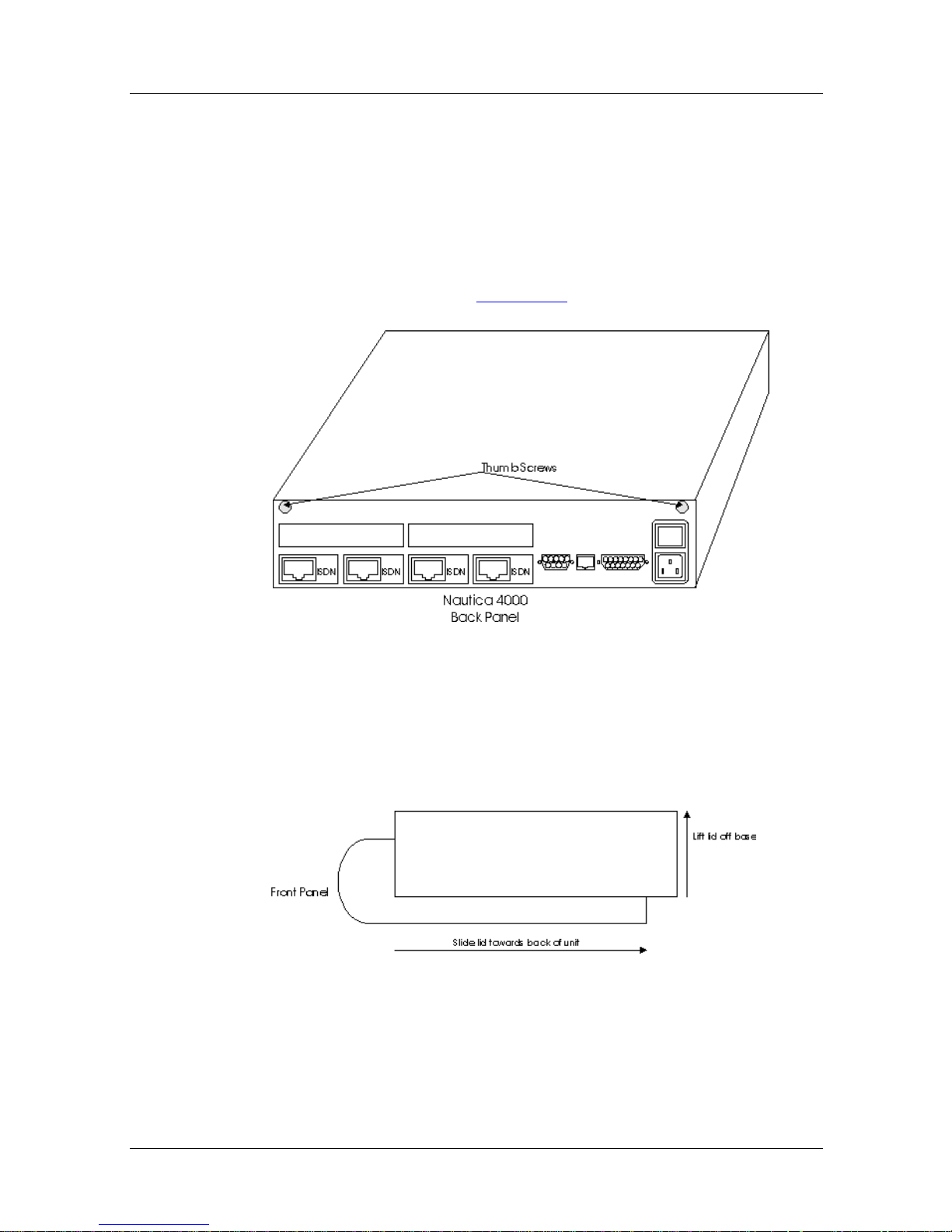
1. Unscrew the thumbscrews located on the back panel of
the Nautica 4000 (Figure 1-1
).
Figure 1-1. Thumbscrews on the Nautica 4000 Back
Panel
2. Slide the lid of the unit about one inch towards the back
of the unit, and then lift off the lid.
Figure 1-2. Removing the Lid
3. Insert the relevant module referring to the relevant
chapter in this manual for instructions.
1-2 300275-D Rev. 00
Page 17

Closing the Nautica 4000
After the module has been installed into the Nautica 4000 (refer
to the relevant module chapter within this manual), close th e unit
by doing the following:
1. Place the lid down over the unit about an inch short of the
front panel.
2. Slide the lid into place and then fasten the thumbscrews.
3. Reconnect all network and ISDN cables.
4. Reconnect the power cable and turn the unit on.
Opening Nautica Routers
300275-D Rev. 00 1-3
Page 18

Page 19

Chapter 2
Nautica BRI-ST/BRI-U Module
ISDN Basic Rate Interface ST (BRI-ST) and Basic Rate Interface
U (BRI-U) modules allow access to the ISDN public switched
services by providing dual 64Kbp/s data channels to the network.
This chapter includes the following sections:
• Checklist (page 2-2
• Installing the BRI Module (page 2-2
• Using the BRI Module (page 2-5
• BRI-U LED Operation (page 2-6
)
)
)
)
300275-D Rev. 00 2-1
Page 20

Nautica Modules Installation Guide
Checklist
The Nautica BRI module comes in two different forms, the
BRI-U and the BRI-ST. Your BRI package should include the
following items:
• One BRI-ST or BRI-U module
• One black or red ISDN cable (RJ-45 to RJ-45)
• One RJ-11 to RJ-45 ISDN cable (BRI-U only)
• One blanking panel with four screws
If any of these items are missing, contact the supplier of the
equipment.
Installing the BRI Module
Danger:
that the host is powered off.
To install the B RI module:
1. Open the Nautica 4000 (see Chapter 1).
2. If the module is separate from the blanking panel, att ach
Before attempting to install the BRI module, ensure
the BRI module to the blanking panel using the two
screws provided (Figure 2-1
).
2-2 300275-D Rev. 00
Page 21
Nautica BRI-ST/BRI-U Module
Figure 2-1. Connecting the BRI Module and
Blanking Panel
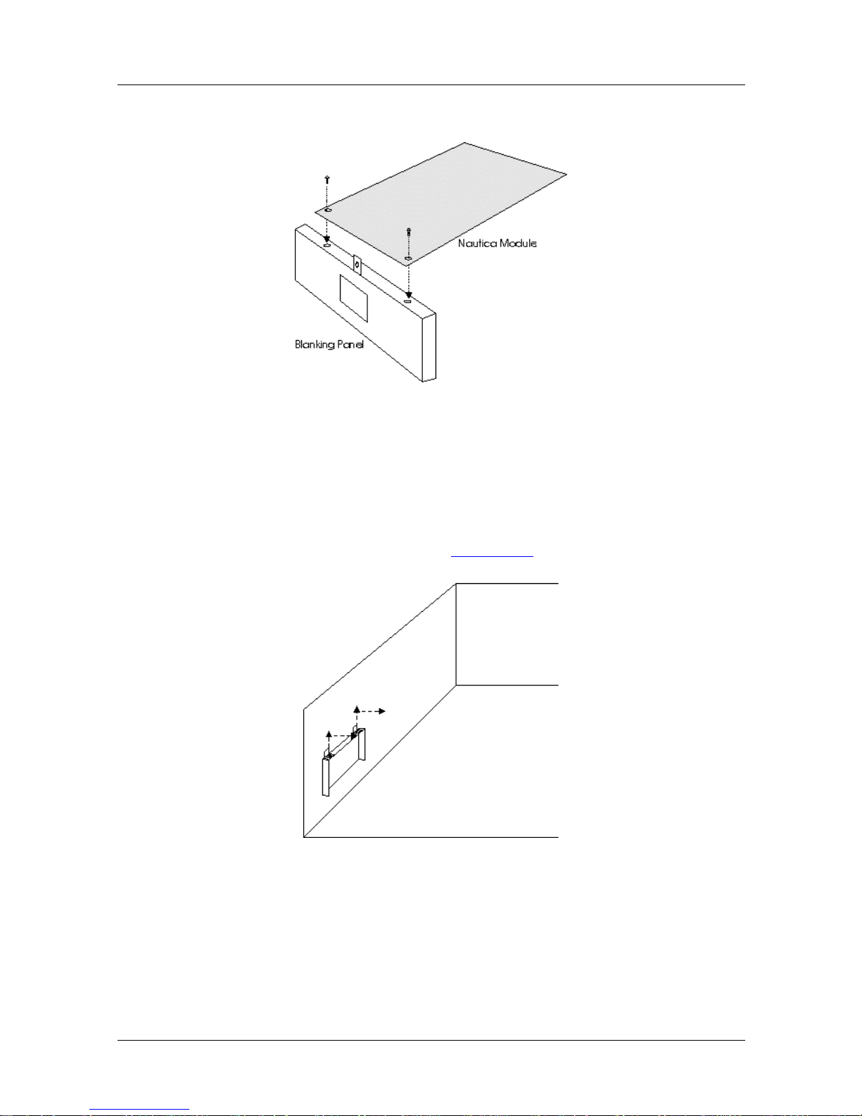
3. Remove the exisiting blanking panel from the Nautica
4000 by loosenin g the scr ews and sl iding the pa nel up and
then out of the host (Figure 2-2
).
Figure 2-2. Removing the Existing BRI Blanking
Panel
300275-D Rev. 00 2-3
Page 22
Nautica Modules Installation Guide
If you are installing the BRI module into the upper layer
of the Nautica 4000, ensure that an ISDN+ module has
been installed to support the BRI module(s) (Chapter 4).
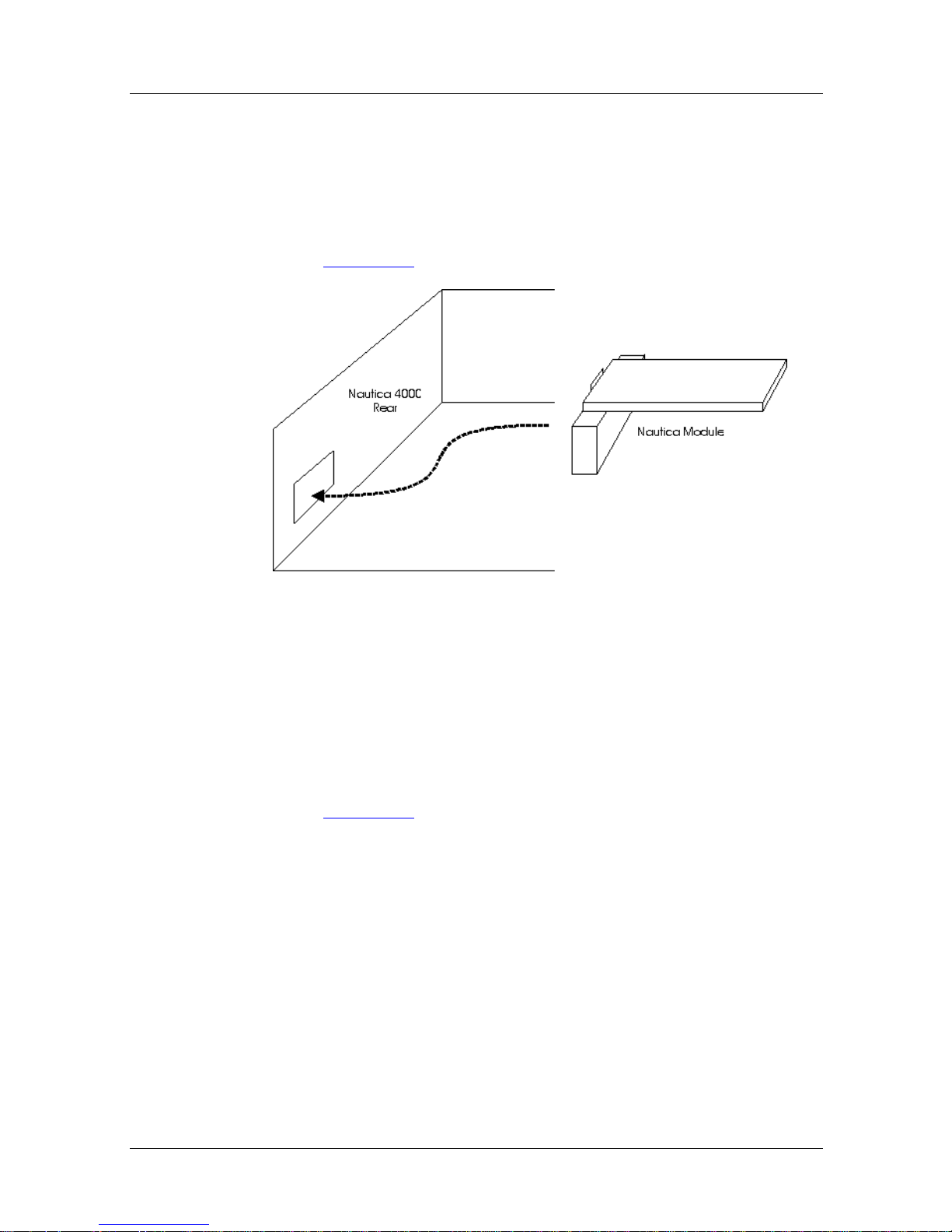
4. Insert the BRI module from within the Nautica 4000; do
not push it through the hole from the rear of the unit
(Figure 2-3
).
Figure 2-3. Inserting the BRI Module
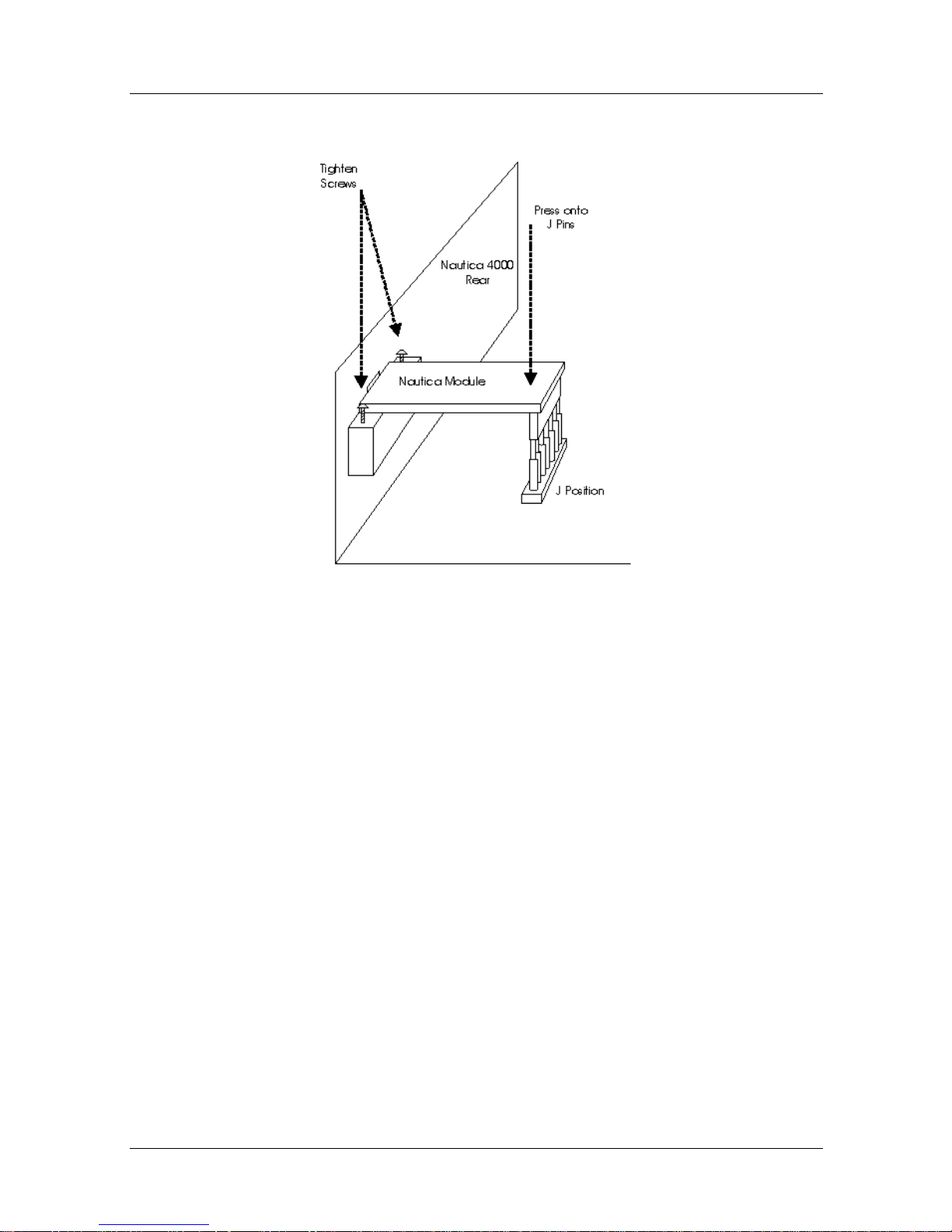
5. Press the spring f ingers o n the front of the blanking plate
tightly against the Nautica 4000. When both rows of pins
are lined up under the BRI module, press the back of the
BRI module down onto the connector pins and tighten the
screws on the blanking panel so that the module is secure
(Figure 2-4
).
2-4 300275-D Rev. 00
Page 23
Nautica BRI-ST/BRI-U Module
Figure 2-4. Positioning the BRI Module
6. Close the Nautica 4000 (see Chapter 1).
7. The BRI-ST module requires the use of an NT1 for
proper network termination of the ISDN line. Connect
the ISDN cable from the BRI-ST module to the NT1
connector labelled S/T. In North America, if you have a
stand alone NT1, you require another cable from the
NT1 U connector directly to the ISDN wall socket.
8. Turn on the unit.
Using the BRI Module
The BRI module is automatically detected by the Nautica 4000.
Configuration can be performed using either the NauticaRS
software or Nautica Wizard. For more information about these
software packages, refer to the relevant online documentation.
300275-D Rev. 00 2-5
Page 24

Nautica Modules Installation Guide
BRI-U LED Operat ion
The BRI-U module has an extra green LED, located in the top
right corner of the ISDN connector. This LED has the following
operation:
• Flashes at 8 Hz (rapid flashing) for 0.5 seconds when the host
is attempting to establish a link between the BRI-U mo dule
and the ISDN network switch.
• Flashes at 1 Hz (slow flashing) when a link is established and
the host is operating normally, whether or not it is sending
data.
• Is off if the unit is not receiving a signal. This means that the
host is not connected to the telephone line or the ISDN
network switch is no t responding. Contact the telephone
company if you believe the ISDN network switch is not
responding.
The LED should not remain on constantly. If it does, there is a
faulty electrical connection inside the host, and you should seek
technical support as follows:
• If you purchased a service contract for your Bay Networks
product from a distributor or authorized reseller, contact the
technical support staff for that distributor or reseller for
assistance.
• If you purchased a Bay Networks service program, call
1-800-2LANWAN.
2-6 300275-D Rev. 00
Page 25

Chapter 3
Nautica Modem Module
Each Nautica modem module holds fou r analog modems. You can
install up to four modem mod ules into the Nautica 4000
providing up to 16 modems.
The Nautica modems operate at a maximum speed of 33600 bps.
This chapter includes the following sections:
• Checklist (page 3-2
• Installing the Nautica Modem Module (page 3-2
• Using the Nautica Modem Module (page 3-5
)
)
)
300275-D Rev. 00 3-1
Page 26
Nautica Modules Installation Guide
Checklist
The Nautica modem package should include the following items:
• One Nautica modem module
Note:
Nautica 4000 it is attached to a carrier card. This card is not
present if the modem is ordered for attaching to an ISDN+ card
(Chapter 3
• Four plastic st andof fs (onl y if the modem i s to be instal led on
If any of these items are missing, contact the supplier of your
equipment.
If the modem is to be installed on the base board of the
).
the base board)
Installing the Nautica Modem Module
Danger:
Module, e nsure the Na utica 4000 is powered off.
Before attempting to install the Nautica Modem
To install the Nautica modem module:
1. Open the Nautica 4000 (see Chapter 1).
If you are attaching the modem to the base board of the Nautica
4000, proceed to Step 2; if you are attaching the modem to the
ISDN+ card, proceed to Step 5.
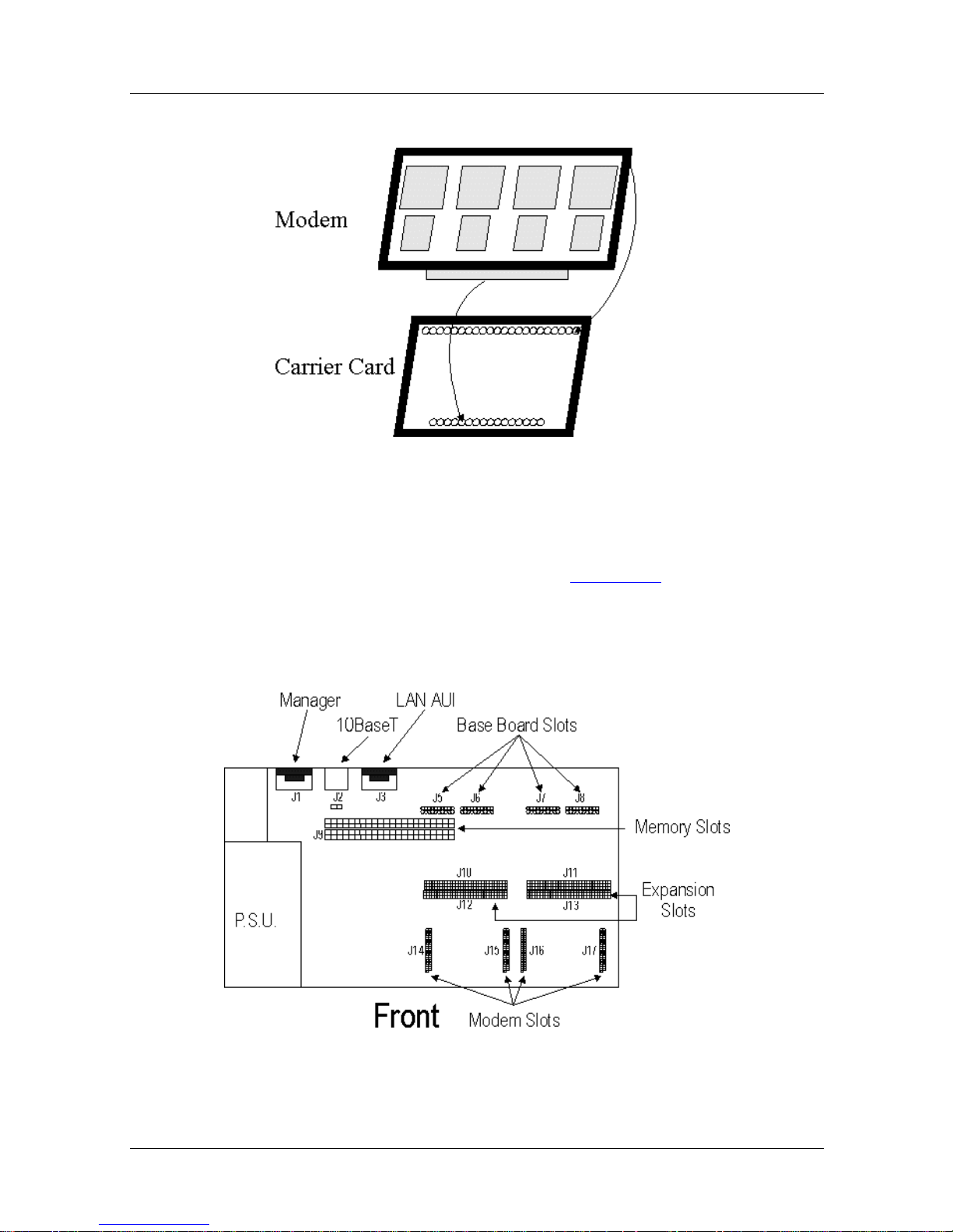
2. If the modem is to be installed on the bas e board of the
Nautica 4000, and it has become separate from its carrier
card, line up the pins on the carrier card with the slots on
the modem and push the two units firmly together
(Figure 3-1
3-2 300275-D Rev. 00
).
Page 27
Nautica Modem Modu le
Figure 3-1. Re-Attaching the Modem to the Carrier Card
3. The modem and carrier card are placed onto positions
J14 and J15 or J16 and J17 (Figure 3-2
). Inset the four
plastic standoffs into the holes around the selected
position.
Figure 3-2. Nautica Modem Connector Positions
300275-D Rev. 00 3-3
Page 28
Nautica Modules Installation Guide
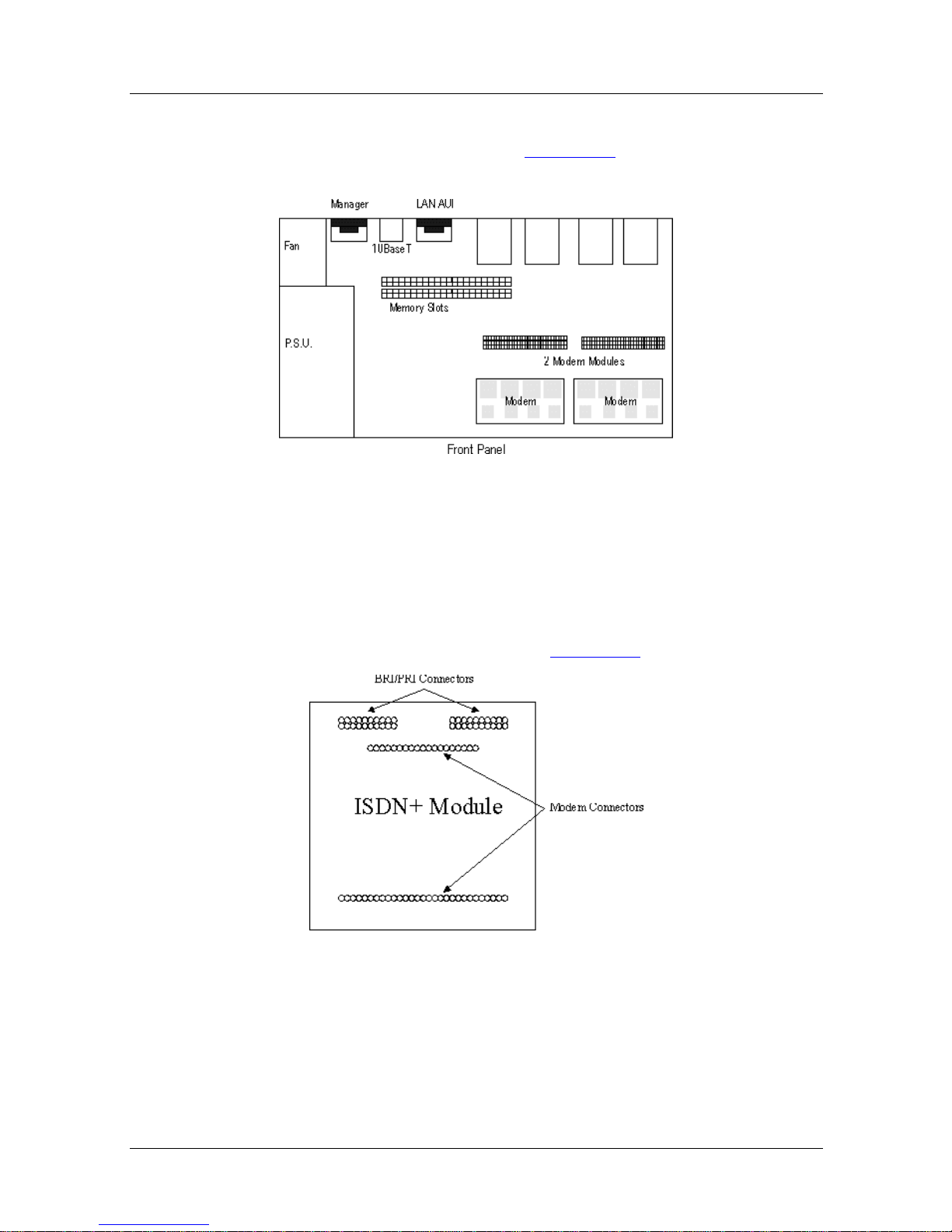
4. The carrier card has orientation pins so that it can only
be fitted one way. As in Figure 3-3
, the small chips on the
top of the modem should be facing th e front of the unit.
Figure 3-3. Nautica Modems on the Base Board
5. If you are adding modems to an ISDN+ card, first install
the ISDN+ card into the Nautica 4000 (Chapter 4).
6. The modem is inserted on the two rows of pins in the
centre of the ISDN+ card (Figure 3-4
).
Figure 3-4. ISDN+ Module Modem Connectors
3-4 300275-D Rev. 00
Page 29
Nautica Modem Modu le
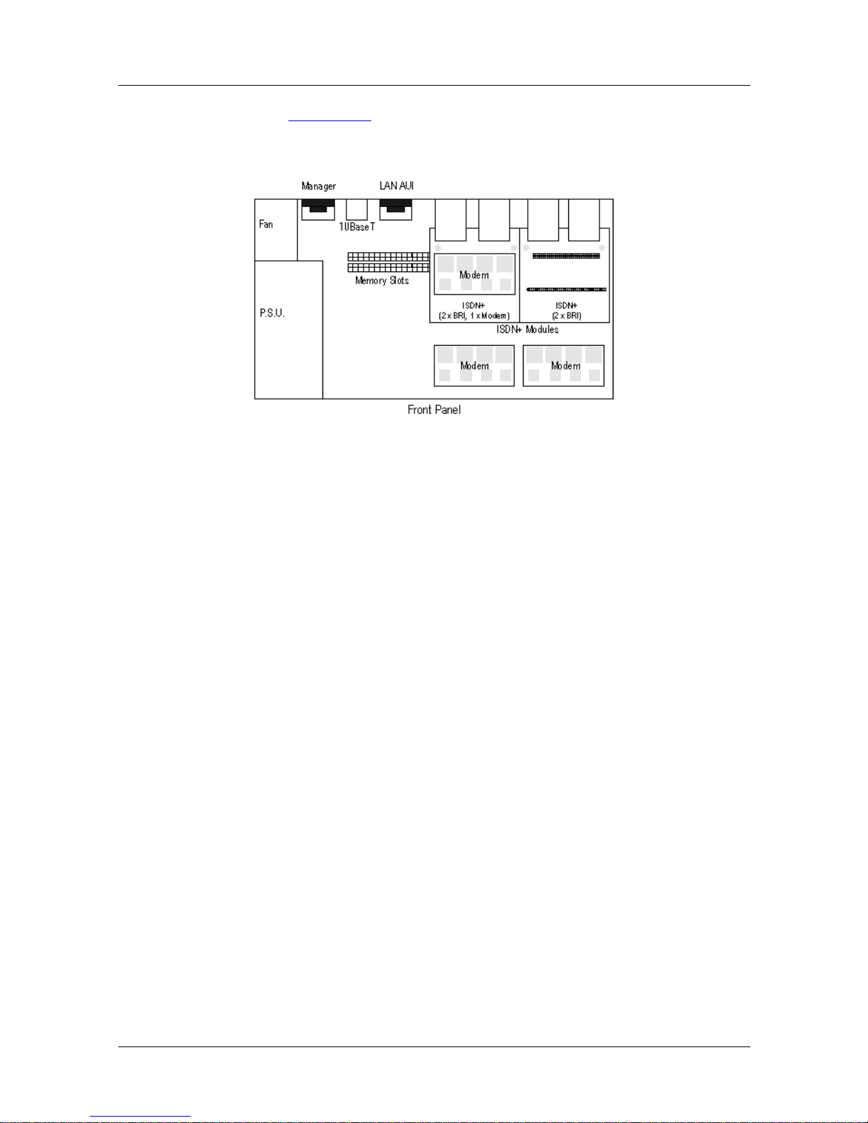
7. Figure 3-5 below shows a Nautica 4000 with two base
board modems an d one modem installed on an ISDN+
module:
Figure 3-5. ISDN+ and Base Board Modems
Using the Nautica Modem
The Nautica Modem module is automa tically detected by the
Nautica 4000. Configuration of the module can be performed
using either the NauticaRS software or Nautica W izard. For mor e
information about these packages, refer to the relevant online
documentation.
300275-D Rev. 00 3-5
Page 30

Page 31

Chapter 4
Nautica ISDN+ Module
The Nautica ISDN+ module allows one modem (in addition to
two modems on the base board) and up to two BRI-U or BRI-ST
modules to be installed in the Nautica 4000. The Nautica 4000
supports up to two ISDN+ modules.
This chapter includes the following sections:
• Checklist (page 4-2
• Installing the ISDN+ Module (page 4-2
)
)
300275-D Rev. 00 4-1
Page 32
Nautica Modules Installation Guide
Checklist
The Nautica ISDN+ module package should include the
following items:
• One ISDN+ module
• Two plastic standoffs
If any of these items are missing, contact the supplier of the
equipment.
Installing the ISDN+ Module
Danger:
ensure that the Nautica 4000 is powered off.
To install the ISDN+ module:
1. Open the Nautica 4000 (see Chapter 1).
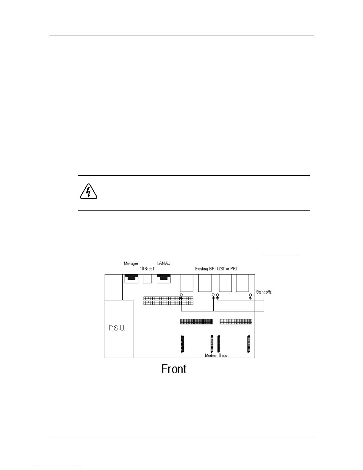
2. Press the standoffs into the relevant holes (Figure 4-1
Before attempting to install the ISDN+ module,
).
Figure 4-1. ISDN+ Standoff Positions
4-2 300275-D Rev. 00
Page 33
Nautica ISDN+ Module
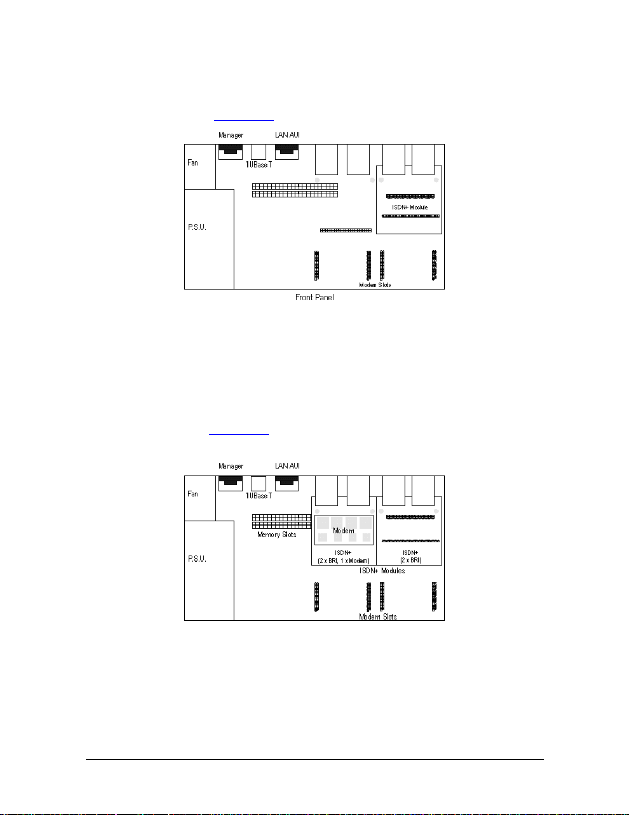
3. Insert the ISDN+ onto the standoffs and the expansion
slots, ensuring the unit is pressed firmly into place
(Figure 4-2
).
Figure 4-2. Positioning the ISDN+ Module
4. Once in position, an additional modem (Chapter 3), or up
to two BRI-U or BRI-ST modules (Chapter 2), can be
fitted to the board.
5. Figure 4-3
shows a Nautica 4000 with both ISDN+
modules installed.
Figure 4-3. Nautica 4000 with Two ISDN+ Modules
6. Close the Nautica 4000 (see Chapter 1).
7. Turn on the unit.
300275-D Rev. 00 4-3
Page 34

Page 35

Chapter 5
Nautica WAN Modules
The Nautica WAN comes in three variants, V.11, V.24 and V.35.
The modules allow one WAN port to be add ed to the Nautica
4000.
The V.11 WAN port provides a standard V.11/X.21 DTE
connection, the V.24 WAN port provides a standard V.24 DTE
connection and the V.35 WAN port provides a standard V.35 DTE
connection via the appropriate cable (ordered separately).
The modules may be connected via an appropriate network
connection to a companion unit at a remote site.
This chapter contains the following sections:
• Checklist (page 5-2
• Installing the Nautica WAN Module (page 5-2
• Using the Nautica WAN Module (page 5-6
)
)
)
300275-D Rev. 00 5-1
Page 36

Nautica Modules Installation Guide
Checklist
The Nautica WAN module is supplied with:
• One Nautica WAN V.11, V.24 or V.35 module
• Two hex screw-lock assemblies
• One replacement panel for Nautica WAN module
If any of the abov e items are missing, contact the supplier of your
equipment.
Cables for connection to digital leased circuits must be ordered as
separate items (refer to the Bay Networks price list). The Nautica
WAN cables are as follows:
• Nautica WAN V.11 3 meter cable (labelled 300285-A)
• Nautica WAN V.24 3 meter cable (labelled 300286-A)
• Nautica WAN V.35 3 meter cable (labelled 300287-A)
Installing the Nautica WAN Module
To install the Nautica WAN module:
Danger:
ensure the Nautica 4000 is powered off.
1. Open the Nautica 4000 unit (Chapter 1).
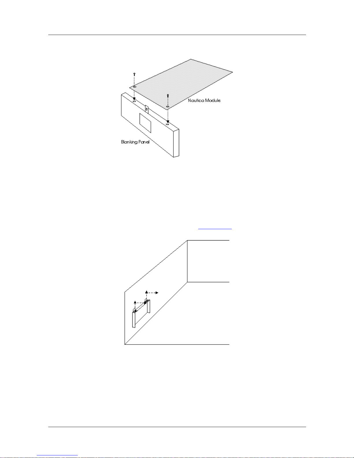
2. If the module is separate from the blanking panel, att ach
Before attempting to install the Nautica W AN module,
the Nautica WAN module to the blanking panel using the
two screws pr ovided (Figure 5- 1
).
5-2 300275-D Rev. 00
Page 37
Nautica WAN Modules
Figure 5-1. Connecting the Module and Blanking
Panel
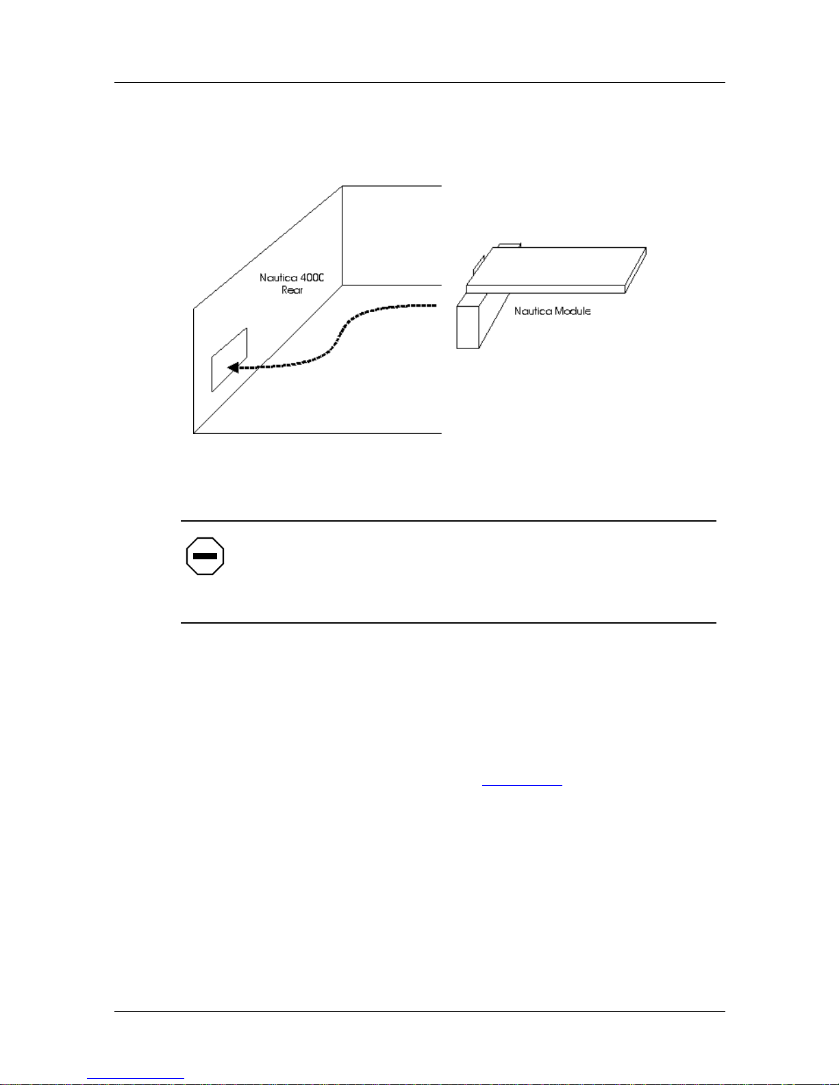
3. Remove the existing panel from the Nautica 4000 unit by
loosening the screws and sliding the panel into and then
out of the Nautica 4000 (Figure 5-2
).
Figure 5-2. Removing the Existing Nautica WAN
Blanking Panel
300275-D Rev. 00 5-3
Page 38
Nautica Modules Installation Guide
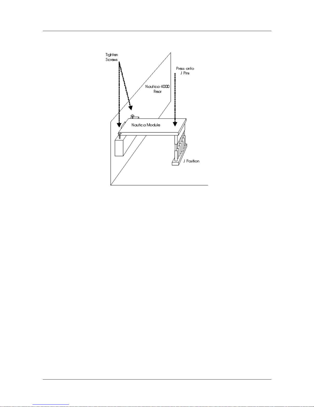
4. The Nautica WAN is inserted from within the Nautica
4000; it is not pushed through the hole from the rear of
the unit.
Figure 5-3. Inserting the Nautica WAN
Caution:
Do not install the Nautica WAN module onto an
ISDN+ module (Chapter 4) as the ISDN+ module cannot
support a Nautica WAN (installation on an IS DN+ may dam age
the Nautica 4000).
5. The spring fingers on the fr ont of the blanking panel need
to be presse d tightly aga inst the Naut ica 4000. When both
rows of pins are lined up under the Nautica W AN module,
press the back of the Nautica WAN down onto the
connector pins and tighten the screws to the rear panel so
that the module is secure (Figure 5-4
).
5-4 300275-D Rev. 00
Page 39
Nautica WAN Modules
Figure 5-4. Positioning the Nautica WAN
6. Close the Nautica 4000 unit (Chapter 1).
7. Connect the WAN cable to the Nautica WAN module.
8. Turn on the unit.
300275-D Rev. 00 5-5
Page 40

Nautica Modules Installation Guide
Using the Nautica WAN Module
The Nautica WAN module is automatically detected by the
Nautica 4000 unit. Further configuring can be performed using
either the NauticaRS or Nautica Wizard. For more infor mation on
these software packages, refer to the relevant on-line
documentation.
5-6 300275-D Rev. 00
Page 41
Chapter 6
Nautica Memory Module
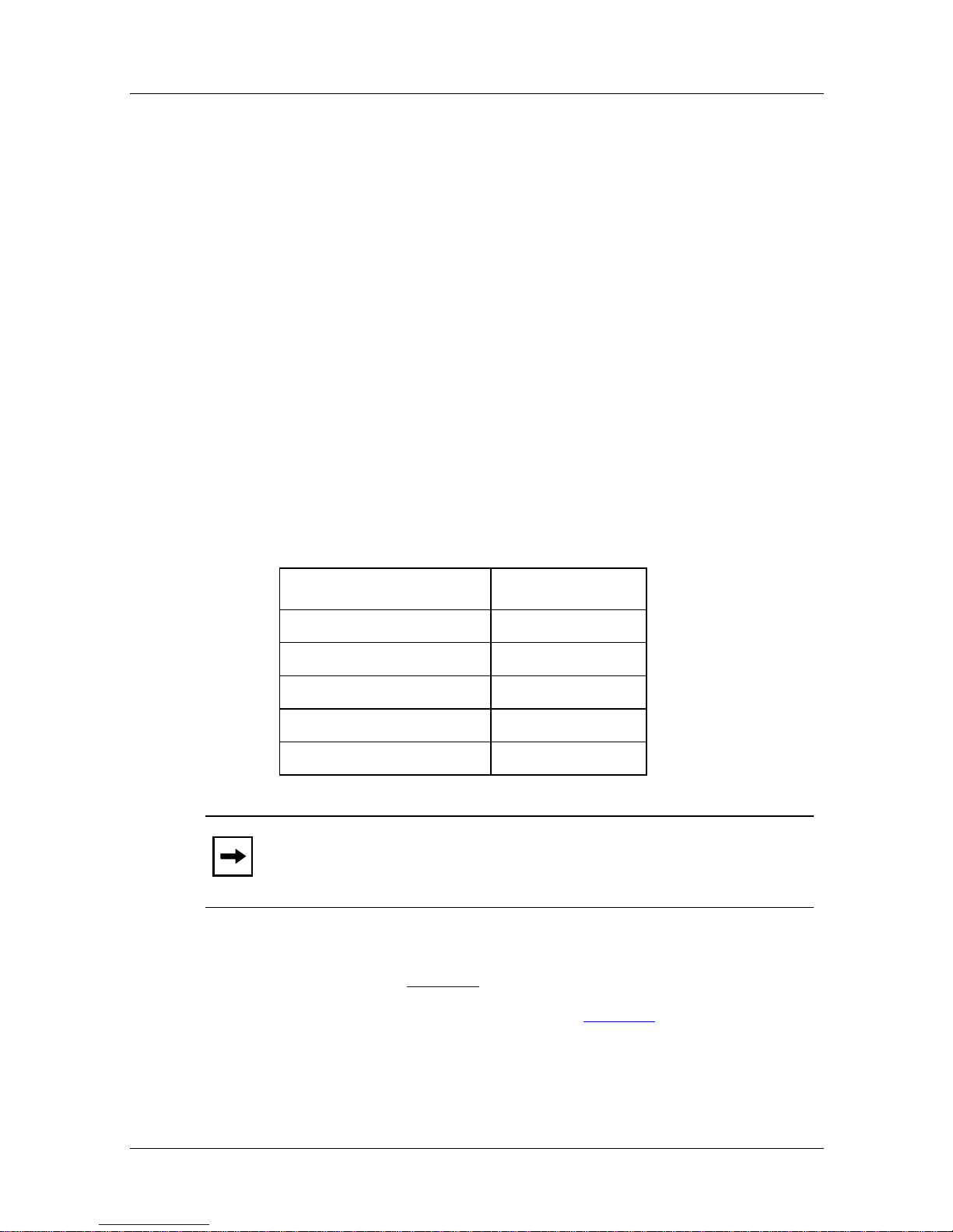
The Nautica Memory module module allows the user to increase
the memory capacity of the Nautica 4000. Memory is pro vided in
4 and 16 Mbyte modules and these modules can be combined in
the following ways:
Table 6-1. Nautica Memory Combinations
Modules Total Memory
1 x 4Mb 4Mb
1 x 4Mb + 1 x 4Mb 8Mb
1 x 16Mb 16Mb
1 x 16Mb + 1 x 4 Mb 20Mb
1 x 16Mb + 1 x 16Mb 32Mb
Note:
parity and an access time of 70 ns or faster.
This chapter includes the following sections:
• Checklist (page 6-2
• Installing the Memory Module (page 6-2
The SIMMs must be 72 pin, Fast Page Mode with no
)
)
300275-D Rev. 00 6-1
Page 42
Nautica Modules Installation Guide
Checklist
The Nautica Memory module package should include the
following items:
• One Memory module of the specified amount (4 or 16Mb)
If any of these items are missing, contact the supplier of the
equipment.
Installing the Memory Module
Danger:
ensure that the host is powered off.
To install the Memory module:
1. Open the Nautica 4000 (see Chapter 1).
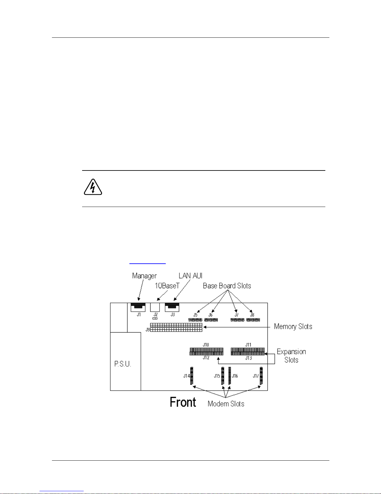
2. Memory is installed onto position J9 in the Nautica 4000
Before attempting to install the Memory module,
(Figure 6-1
).
Figure 6-1. Nautica 4000 J Positions
6-2 300275-D Rev. 00
Page 43
Nautica Memory Module
Due to the size constraints of the Nautica 4000, position
J9 runs underneath the ISDN+or QuadWAN module
installed onto the ex pan sion slot at p osition s J 10 to J13. If
you have an ISDN+ module installed , remove it and any
attached BRI-U/BRI-STs and modem modules that may
be attached to it.
For information on the ISDN+ module, refer to
Chapter 4. For more information on the BRI-U and
BRI-ST modules, refer to Chapter 2. Chapter 3 provides
information on the Nautica modem module.
3. Position J9 (Figure 6-1
) allows for two Memory modules
to be installed at any one time. Use the combination of
modules you require to achieve optimum memory.
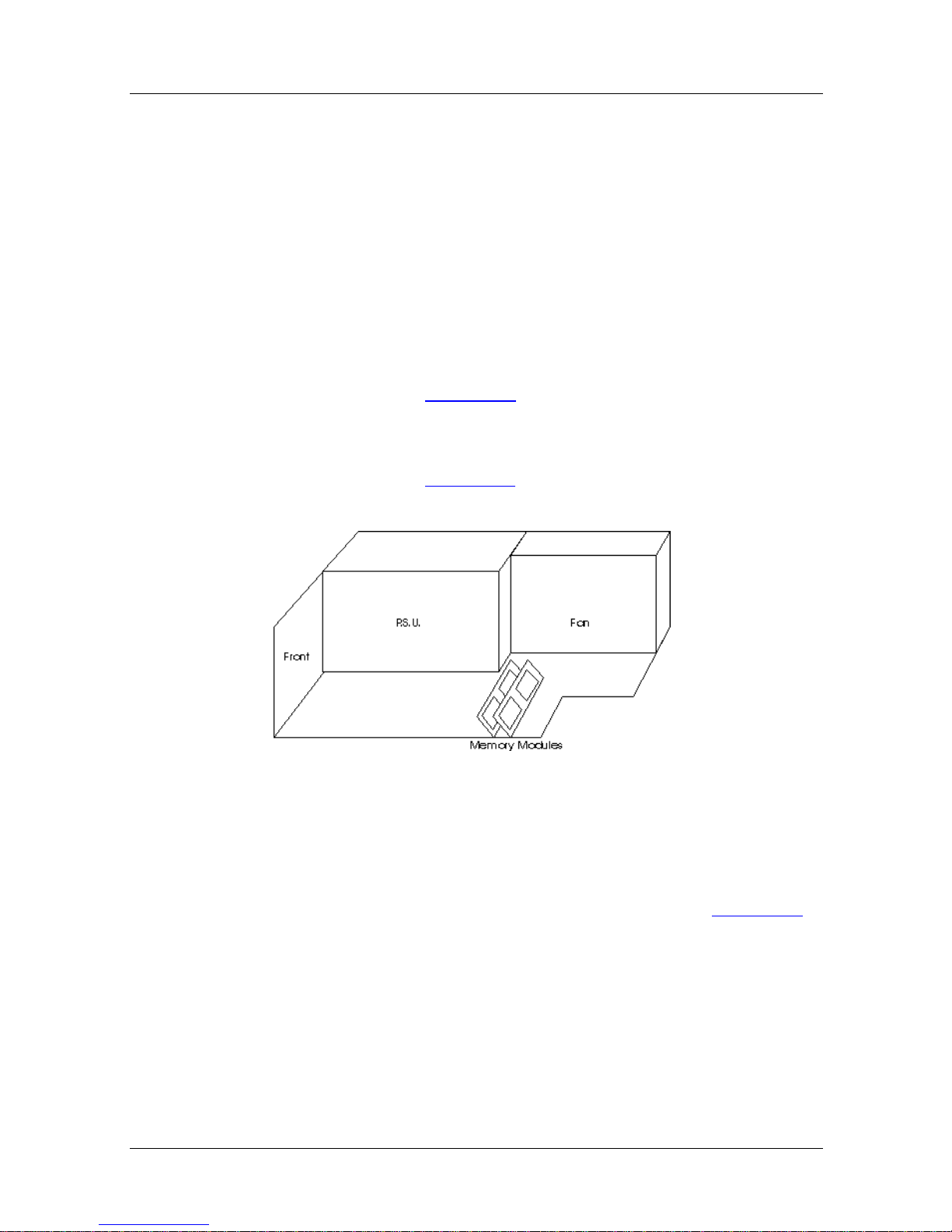
4. As show n in Figur e 6-2
, the Memory modules are inserted
at an angle to the base of the Nautica 4000.
Figure 6-2. Positioning the Nautica Memory Module
The 72 pins at the bottom of the Memory module are
inserted into the slots at position J9. The chips should
face towards the rear of the unit as shown in Figure 6-2
5. Close the Nautica 4000 (see Chapter 1).
6. Turn on the unit. The new memory is automatically
detected and initialised as part of the normal start up
procedure for the Nautica 4000.
300275-D Rev. 00 6-3
.
Page 44

Page 45

Chapter 7
Nautica QuadWAN Module
The Nautica QuadWAN module provides f our extra V.11 WAN
ports in the Nautica 4000. The QuadWAN can be connected to a
network using an appropriate cable (ordered separately).
This chapter includes the following sections:
• Checklist (page 7-2
• Installing the QuadWAN Module (page 7-2
• Using the Nautica QuadWAN Module (page 7-4
)
)
)
300275-D Rev. 00 7-1
Page 46
Nautica Modules Installation Guide
Checklist
The Nautica QuadWAN module package should include the
following items:
• One Nautica QuadWAN module
If this item is missing, contact the supp lier of the equipment.
A cable is available for the QuadWAN (labelled 300582-A). This
is ordered separately (refer to the Bay Networks price li st).
Installing the QuadWAN Module
Danger:
ensure that the Nautica 4000 is powered off.
To install the QuadWAN module:
1. Sav e the Nauti ca 4000’s configuratio n and set the Nautica
2. Open the Nautica 4000 (see Chapter 1).
Before attempting to install the QuadWAN module,
4000 to the factory defaults using either the BCC™ or
Nautica Wizard.
The QuadWAN module can be installed using slots 5 and 6 or
slots 7 and 8 (refer to the diagram on the back of the Nautica
4000 for slot numbers).
7-2 300275-D Rev. 00
Page 47
Nautica QuadWAN Module
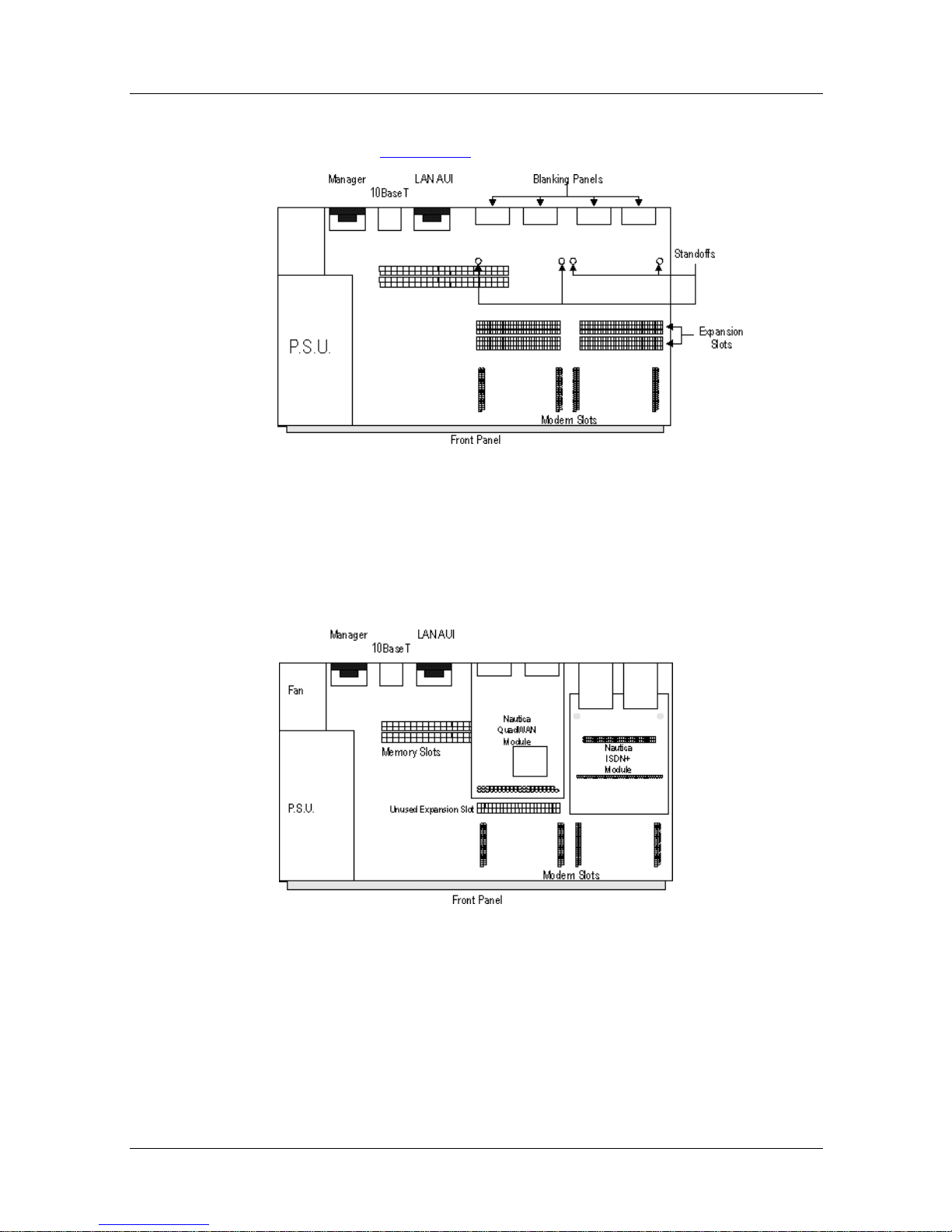
3. Remove any plastic standoffs and two of the blanking
plates (Figure 7-1
):
Figure 7-1. Standoffs and Blanking Panels
The Nautica 4000 can hav e two QuadWAN modules installed
or one QuadWAN and one ISDN+ module. Expansio n sl ots
can also be left empty.
Figure 7-2. Nautica QuadWAN and ISDN+ Modules
4. Insert the module, pressing the rear connectors firmly
into the front of the two expans i on slots.
5. Tighten the nuts using the appropriate spanner.
300275-D Rev. 00 7-3
Page 48

Nautica Modules Installation Guide
6. Close the unit (see Chapter 1).
7. Turn on the unit.
8. Restore the router’s configuration (if required).
Using the Nautica QuadWAN Module
The Nautica QuadWAN module is automatically detect ed by the
host unit. Further configuring can be performed using either the
NauticaRS software or Nautica Wizard. For more information
about these software packages, refer to the relevant online
documentation.
7-4 300275-D Rev. 00
Page 49

Chapter 8
Nautica PRI Module
The Nautica ISDN Primary Rate Interface (PRI) module allows
access to the ISDN public switched services by providing up to
30 channels to the network in Europe and 23 in North America.
The PRI module provides a large range of options. Refer to your
host specific application documentation for further details.
This chapter includes the following sections:
• Checklist (page 8-2
• Installing the PRI Module (page 8-2
• Using the PRI Module (page 8-6
)
)
)
300275-D Rev. 00 8-1
Page 50
Nautica Modules Installation Guide
Checklist
The Nautica PRI module package should include the following
items:
•One PRI module
• One 16 Mb Memory module
• One black or red ISDN cable
• One black or red ISDN cable open connection (Europe only)
• One blanking panel with four screws
If any of these items are missing, contact the supplier of the
equipment.
Installing the PRI Module
Danger:
that the Nautica 4000 is powered off.
Note:
the Nautica 4000.
To install the PR I module:
1. Save the router’s configuration a nd set the unit to the
2. Open the host unit (see Chapter 1).
3. Install the 16 Mb memory module (Chapter 6).
Before attempting to install the PRI module, ensure
The PRI module requires at least 16 Mb of memory in
factory defaults using either the BCC or Nautica Wizard.
The PRI module can be inst alled in slots 1 or 3 or, if you hav e
an ISDN+ fitted, slots 5 or 7 (refer to the diagram on the back
of the Nautica 4000 for slot numbers). The slot next to the
installed PRI must remain empty.
8-2 300275-D Rev. 00
Page 51
Nautica PRI Module
If you are installing the PRI module into the upper layer of
the Nautica 4000, ensure that an ISDN+ module has been
installed to support the PRI (Chapter 4).
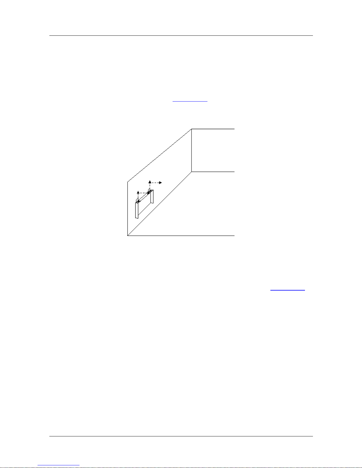
4. Remove the existing blanking panel from the host unit by
loosening the screws and slidin g t he panel up and then
out of the host (Figu re 8-1
).
Figure 8-1. Removing the Existing Blanking Panel
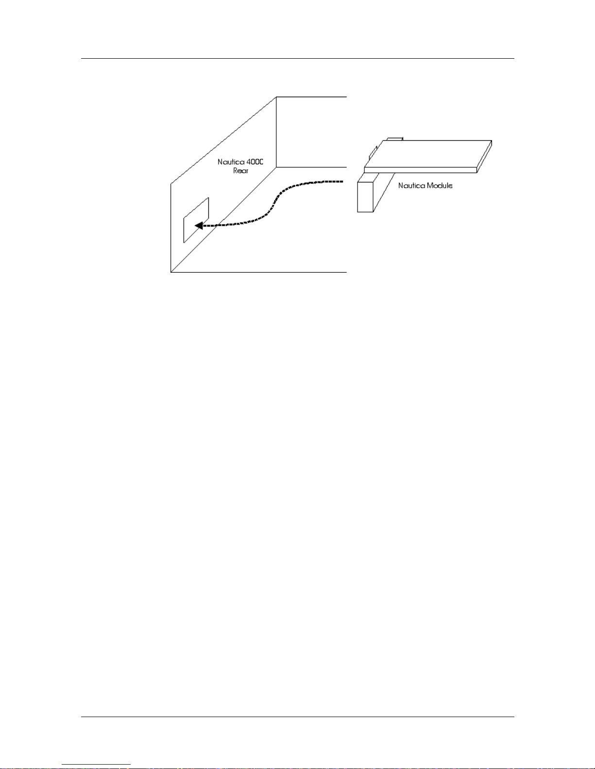
5. Insert the PRI fr om wit hin th e Nautica 4000; d o not push
it through the hole from the rear of the unit (Figure 8-2
).
300275-D Rev. 00 8-3
Page 52
Nautica Modules Installation Guide
Figure 8-2. Inserting the PRI
6. Press the spring f ingers o n the front of the blanking plate
tightly against the Nautica 4000. When the module is
lined up over the the pins, press the back of the PRI
module down onto the jumper pins and tighten the screws
on the rear panel so that the module is secure.
7. Close the host unit (see Chapter 1).
8-4 300275-D Rev. 00
Page 53

Nautica PRI Module
8. If you are using the European PRI module, use the
appropriate cable to connect the PRI module to the ISDN
network, following any instructions supplied by your
service provider.
If using the RJ-45 to open connection cable, the
connections are as follows:
Wire Colour Name
White/Orange Rx Ring
Orange Rx TIP
Blue Tx Ring
White/Blue Tx TIP
9. Turn on the unit.
10. Restore the router configuration (if required).
300275-D Rev. 00 8-5
Page 54

Nautica Modules Installation Guide
Using the PRI Module
Warning:
Do not connect the PRI module to the network until
you have configured the correct switch type using Nautica
Wizard or the BCC.
The North American PRI module uses several different switch
types. If you do not know your switch type, refer to your service
provider.
If you are using the 4ESS switch type, it is necessary to do wnload
a different software image using the Device Configuration option
in Nautica W izard. Th e software image c an be found on the CD in
the \Upgrade\ISDNTA\PRI directory.
No switch type is required if you are using th e E1 PRI module in
Europe as the software defaults to ETSI.
When using the PRI module o uts ide Europe or North America it
may be necessary to download the country specific software to
the PRI module. The software files are listed in the ReadMe.txt
file on the CD in the \Upgrade\ISDNTA\PRI directory.
For more infor mation about Nautica W izard and the BCC, re fer to
the relevant online documentation.
8-6 300275-D Rev. 00
Page 55

Appendix A
Additional Regulatory Information
This appendix contains additional safety regualations and
includes the following sections:
• Power Supply (page A-2
• Port Specifications (page A-3
• Additional German Requirements (page A-5
)
)
)
300275-D Rev. 00 A-1
Page 56

Power Sup ply
Power is provided via a standard IEC 320 (CEE-22) connector
through an inlet on the rear of the unit.
A single power cable, 2 metres in length is supplied with the unit.
This cable should be connected to a suitable power supply. The
power connector is the primary disconnect dev ice for the unit.
You must ensure that the unit is installed near a power outlet and
that the outlet is accessible.
The power cable supplied with the unit is fitted with a moulded
connector for connection to the stand ard sock et o utlet. The use o f
adaptors is not recommended and may invalidate the product’s
approva l. The wires in the power cab le are coloured in accordance
with the following code:
Nautica Modules Installation Guide
Green and Yellow Earth
Blue Neutral
Brown Live
L’alimentation secteur est fournie par un conn ecteur standard IEC
320 (CEE-22) au travers d’une prise située à l’arrière l’unité.
Un cable d’alimentation secteur de 2 mètres est fourni avec
l’unité. Celui-ci devra être connecté à une alimentation secteur.
La prise secteur est le moyen primaire de déconnexion de l’unité
et vous devez donc vous assurer qu’elle est installée près d’une
prise et que cette prise est accessible.
Le cordon secteur fourni avec l’unité possède un connecteur
moulé pour la connexion à une prise de secteur standard.
L’utilisation d’adapteurs n’est pas recommandée et peut invalider
l’homoligation du produit.
A-2 300275-D Rev. 00
Page 57

Les cables dans le cordon fourni sont colorisés suivant les codes:
Vert et Jaune Terre
Bleu Neutre
Marron Phase
Port Specifications
The ports in a Nautica 4000 are classified as follows:
Port Type Location
LAN 10BASE-T SELV Chassis
LAN AUI SELV Chassis
Additional Regulatory Information
Manager SELV Chassis
BRI TNV1 Chassis
PRI TNV1 Chassis
WAN TNV (within the
limits of SELV)
ISDN (J2) TNV1 BRI-ST Module
Host (J1) SELV BRI-ST Module
Chassis
Interconnection circuits should be such that the equipment
continues to comply with the requirement of section 6.2 fo r
T elecommun ications Network Voltage (TNV) circuits and section
2.3 for Safety Extra Low Voltage (SELV) circuits of
EN60950:1992/A4:1997 after making connections between
circuits.
In order to maintain the independent approval for this module, it
is essential that, when other option modules are introduced which
use or generate hazardous voltages, the minimum creepage and
clearances specified in the table below are maintained between
the module and any other assemblies which use or generate a
voltage.
300275-D Rev. 00 A-3
Page 58

Nautica Modules Installation Guide
The large distance shown in brackets applies where the local
environment within the host is subject to conductive pollution or
dry non-conductive pollution that could become conductive due
to condensation. Failure to maintain these minimum distances
would invalidate approval.
Voltage used or
Clearance (mm) Creepage (mm)
2.0 2.4 (3.8) Up to 50 Vrms or VDC
2.6 3.0 (4.8) Up to 125 Vrms or VDC
4.0 5.0 (8.0) Up to 250 Vrms or VDC
4.0 6.4 (10.0) Up to 300 Vrms or VDC
generated by host or
other modules
For a host or other expansion
module fitted in the host, using or
generating voltages greater than
300V (rms or dc), advice from a
competent telecommunications
engineer must be obtained bef ore
installation of the relevant
equipment.
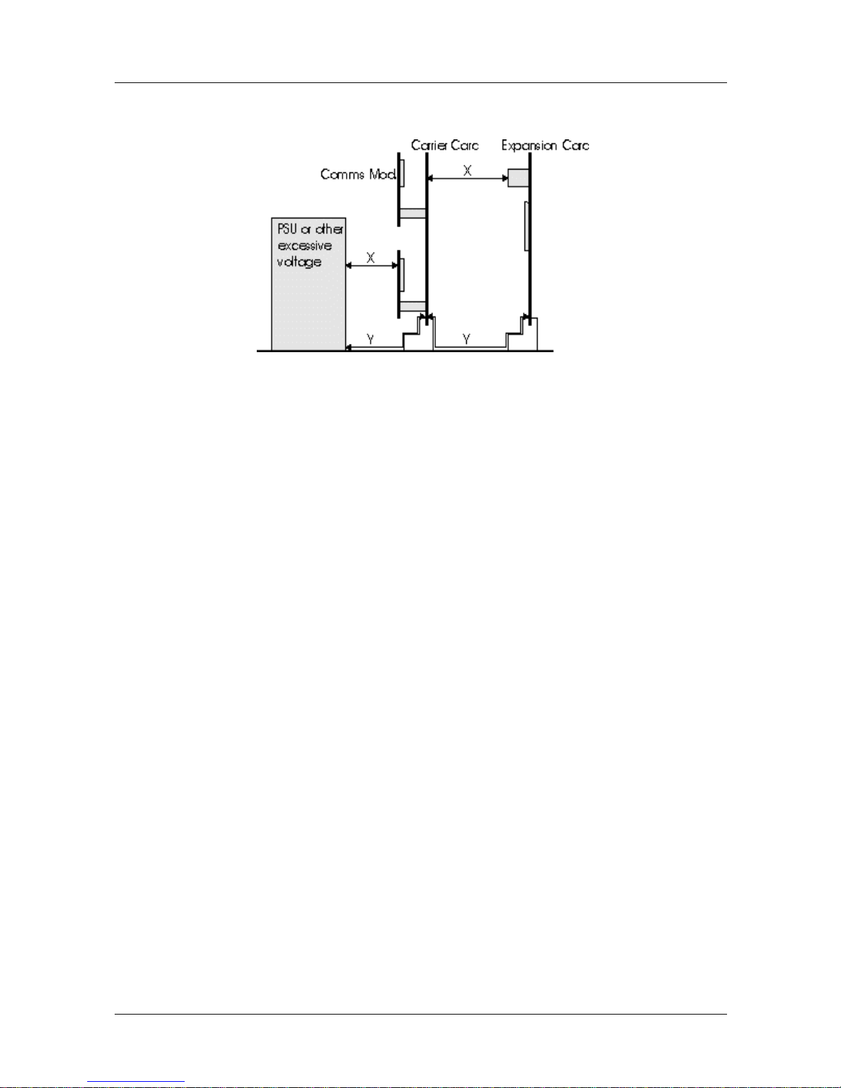
In the following figure, except at the edge connector which plugs
into the host’s expansion slot, clearance distance (X mm) and
creepage (Y mm) as given in the previous table, must be
maintained between the communications module and any other
assemblies that use or generate hazardous voltage.
Above 300 Vrms or VDC
A-4 300275-D Rev. 00
Page 59
Additional Regulatory Information
Clearance and Creepage
Additional German Requirements
Stromversorgung
Der Strom wird über einen serienmäßigen IEC 320 (CEE-22)
Stecker durch eine Einlaßöffnung an der Rückseite des Gerätes
zugeführt.
Ein einzelnes Stromkabel von 2 m Länge wird mit dem Gerät
geliefert. Dieses sollte an eine geeignete Stromversorgung
angeschlossen werden. Der Stromstecker ist die
Haupt-Ausschaltvorrichtung des Geräts, und Sie müssen
sicherstellen, daß das Gerät in der Nähe einer Netzsteckdose
montiert ist und daß dies e erreichbar ist.
Das mit dem Gerät gelieferte Stromkabel ist mit einem geformten
Stecker zum Anschluß an eine Standard-Steckdose ausgestattet.
Die Verwendung von Adapteren wird nicht empfohlen und kann
zur Außerkraftsetzung der Genehmigung des Gerätes führen.
300275-D Rev. 00 A-5
Page 60

Die Drähte im Stromkabel haben unterschiedliche Farben in
Übereinstimmung mit dem folgen den Cod e:
Grün und Gelb Erdung
Blau Neutral
Braun Stromführend
Entsorgung der Batterie
Die Entsorgung des Lithium-Batterie-Moduls muß unt e r
Einhaltung der Entsorgungvorschriften des Herstellers erfolgen.
Portspezificationen
Nautica Modules Installation Guide
Das Nautica 4000 Gerät hat wie folgt klassifizierte Ports:
Port Typ Standort
LAN 10BASE-T SELV Chassis
LAN AUI SELV Chassis
Manager SELV Chassis
BRI TNV1 Chassis
PRI TNV1 Chassis
WAN TNV (innerhalb
der Grenzen von
SELV)
ISDN (J2) TNV1 BRI-ST Modul
Host (J1) SELV BRI-ST Modul
Chassis
A-6 300275-D Rev. 00
Page 61

Additional Regulatory Information
Die Verbindungsschaltungen sollten so beschaffen sein, daß sie
weiterhin den Erfordernissen von Abschnitt 6.2 für
Telecommunications Network Voltage (TNV) Schaltungen und
Abschnitt 2.3 für Safety Extra Low Voltage (SELV) Schaltungen
der bestimmungen EN60950:1992/A4:1997 entsprechen,
nachdem die Verbindung zwisch en den Schaltungen hergestellt
wurde.
Warnung für die Installation des Moduls
Der Strom, welcher vo m Host und allen in der Hostumgebung
installierten Adapterkarten benötigt wird, darf nicht die
Stromspezifikationen für das Hostgerät überschreiten (siehe S.3).
Es ist wichtig, daß auch bei Einführung anderer Optionskarten,
die eine gefährliche Spannung benutzen oder erzeugen, der in
Tabelle 1 angegebene Mindestkriechstrom und die
Mindestspielräume aufrechterhalten werden. Ein geeigenter
Benutzerschutz in Übererinstimmung mit EN 60950 sollte auf der
Karte vorhanden sein. Eine gefährliche Spannung ist bei 42,4V
Spitzenleistung AC oder 60V DC gegeben. Wenn Sie im Zweifel
sind, lassen Sie sich vor der Installation anderer Adapter in das
Hostgerät von einem erfahrenen Techniker beraten.
300275-D Rev. 00 A-7
Page 62

Nautica Modules Installation Guide
Das Gerät muß so installiert sein, daß die in Tabelle 1
aufgeführten Spielraum und Kriechstromentfernungen zwischen
den Karten und anderen Baugruppen, die eine in der
untestehenden Tabelle angegebene Spannung benutzen oder
erzeugen, aufrechterhalten bleiben. Die in Klammer n angegebene
größere Entfernung gilt, wo die örtliche Umgebung im Host
leitfähiger Verschmutzung bzw. trockener nichtleiender
Verschmutzung ausgesetzt ist, welcher aufgrund von
Kondensation leitfähig werden kann. Das Nichteinhalten dieser
Mindestentfernungen kann zur Außerkraftsetzung der
Genehmigung des Gerätes führen.
Kriechstrom Spielräume
2.0 2.4 (3.8) Bis zu 50 V Effektivstrom oder VDC
2.6 3.0 (4.8) Bis zu 125 V Effektivstrom oder VDC
4.0 5.0 (8.0) Bis zu 250 V Effektivstrom oder VDC
4.0 6.4 (10.0) Bis zu 300 V Effektivstrom oder VDC
Bei Einbau eines Hosts oder einer
anderen Erweiterungskarte, die größere
Spannungen al s 300 V (Effektivstrom oder
VDC) benutzen oder erzeugen, muß
vorher Rat von einem kompetenten
Telekommunikations-Sicherheitstechniker
eingolt werden.
Vom Host oder anderen karten
benutzte oder erzeugte Spannung
Über 300 V Effektivstrom oder VDC
Abbildung 2 zeigt die phys ikalische Darstel lung v on Kriechstrom
und Spielräumen.
A-8 300275-D Rev. 00
Page 63
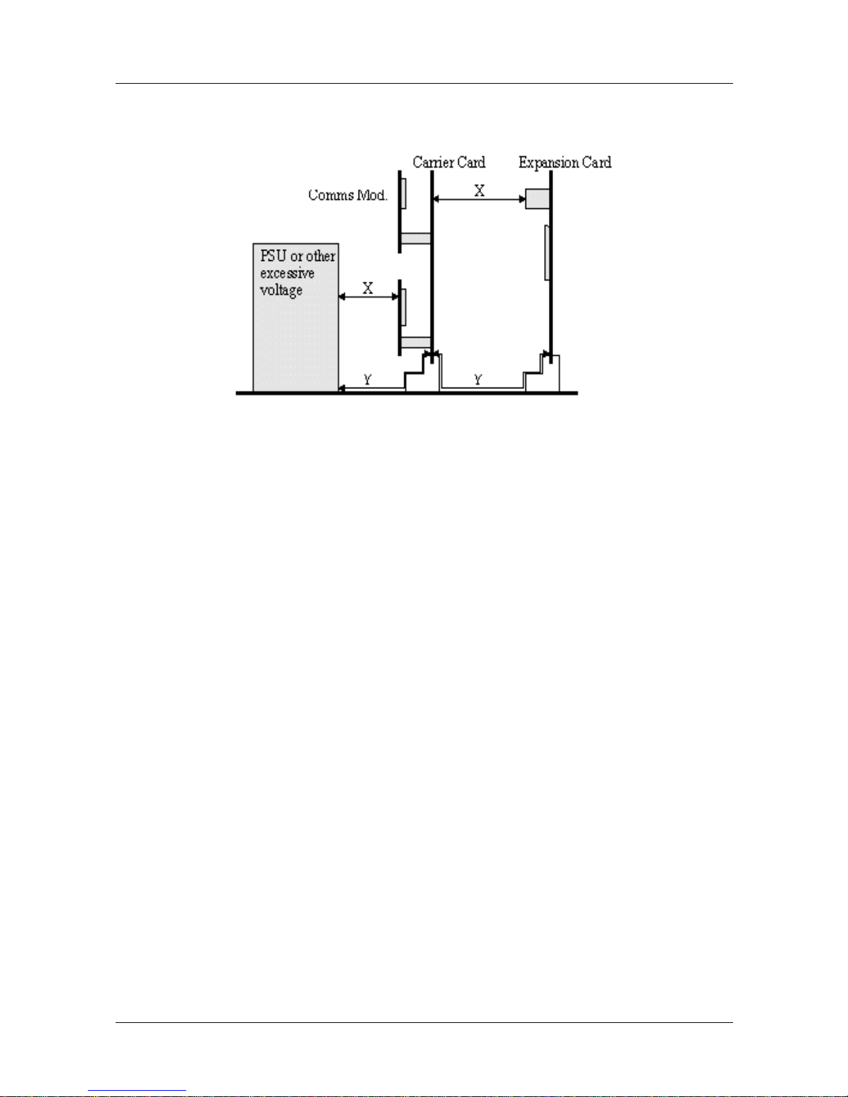
Kriechstrom und Spielräume
Additional Regulatory Information
ISDN-Karten
Ausgenommen an den Randstiftleisen, die in den
Erweiterungsschlitz des Hosts ge steckt werden, muß
Spielraumentfernung X (mm) und Kriechstromentfernung Y
(mm) gemäß Tabelle 1 zwischen d en Kommunikationskarten und
allen anderen Baugruppen, die gefährliche Spannung benutzen
oder erzeugen, aufrechthalten werden.
Das ISDN- Kabel darf nicht an das Telekommunikationssys tem
angeschlossen werden, bevor die Karte in einem Host installiert
wurde, der den notwendigen Schutz für den Benutzer bietet.
Sollte das Hostgerät zu einem späteren Zeitpunkt aus
irgendeinem Grund geöffnet werden müssen, muß das
ISDN-Kabel entfernt werden, bevor Zugang zur
ISDN-Kommunikationskarte möglich ist.
300275-D Rev. 00 A-9
Page 64

 Loading...