

Page 1

Nautica
Configuration
Wizard 5
Reference Guide
Part No. 118814-D Rev. 00
April 1998
Page 2

4401 Great America Parkway 8 Federal Street
Santa Clara, CA 95054 Billerica, MA 01821
Copyright © 1998 Bay Networks, Inc.
All rights reserved. Printed in the UK. April 1998.
The information in this document is subject to change without notice. The statements,
configurations, technical data, and recommendations in this document are believed to be
accurate and reliable, but are presented without express or implied warranty. Users must
take full responsibility for their applications of any products specified in this document.
The information in this document is proprietary to Bay Networks, Inc.
Trademarks
Nautica 200, Nautica 4000, and Bay Networks are registered trademarks and BCC, Bay
Networks Press, and the Bay Networks logo a re trademarks of Bay Ne tworks, Inc.
Microsoft, Windows, and Windows NT are registered trademarks of Microsoft
Corporation.
All other trademarks and registered trademarks are the pr operty of their respective owners.
Restricted Rights Legend
Use, duplication, or disclosu re by the United States Gov ernment is sub ject to restrictio ns as
set forth in subparagraph (c)(1)(ii) of the Rights in Technical Data and Computer Software
clause at DFARS 252.227- 7013.
Notwithstanding any other license agreement t hat may pertain to, or accompany the
delivery of, this computer software, the rights of the United States Government regarding
its use, reproduction, and disclosure are as set forth in the Commercial Computer
Software-Restricted Rights clause at FAR 52.227-19.
Statement of Conditions
In the interest of improving inte rnal design, operational function, and/or reliability, Bay
Networks, Inc. reserves the right to make changes to the products described in this
document without notice.
Bay Networks, Inc. does no t assume an y liabilit y t hat may oc c ur due to the use or
application of the product(s) or ci rcuit layout(s) described herein.
Portions of the code in this so ftware product are Copyright © 1988 , Regents of the
University of California. Al l rights reserved. Redist ribution and use in source and binary
forms of such po rtions are permitted, provided th at the above copyright notice and this
paragraph are duplic ated in all such forms and that any documentation, advertising
materials, and other materials related to such distribution and use acknowledge that such
portions of the software were developed by the University of California, Be rkeley. Th e
name of the University may not be used to endorse or promote products derived from such
portions of the software witho ut speci fic prior written permission.
ii 118814-D Rev. 00
Page 3

SUCH PORTIONS OF THE SOFTWARE ARE PROVIDED “AS IS” AND WITHOUT
ANY EXPRESS OR IMPLIED WARRANTIES, INCLUDING, WITHOUT
LIMITATION, THE IMPLIED WARRANTIES OF MERCHANTABILITY AND
FITNESS FOR A PAR TICULAR PURPOSE.
In addition, the program and information contained herein are licensed only pursuant to a
license agreement that contains restrictions on use and disclosure (that may incorporate by
reference ce rtain limitat ions and notices i m posed by third parties).
118814-D Rev. 00 iii
Page 4

Bay Netw orks, Inc. Software License Agreement
NOTICE: Please carefully read this license agreement before copying or using the
accompanying software or installing the hardware unit with pre-en abled software (each of
which is referred to as “Software” in this Agreement). BY COPYING OR USING THE
SOFTWARE, YOU ACCEPT ALL OF THE TERMS AND CONDITIONS OF THIS
LICENSE AGREEMENT. THE TERMS EXPRESSED IN THIS AGREEMENT ARE
THE ONLY TERMS UNDER WHICH BAY NETWORKS WILL PERMIT YOU TO
USE THE SOFTWARE. If you do not accept these terms and conditions, return the
product, unused and in the original shipping container, within 30 days of purchase to
obtain a credit for the full purchase price .
1. License Grant. Bay Networks, Inc. (“Bay Networks” ) grants the end u s er of the
Software (“Licensee”) a personal, nonexclusive, nontransferable license: a) to use the
Software either on a single computer or, if applicable, on a single authorized device
identified by host ID, for which it was originally acquired; b) to copy the Software solely
for backup purposes in su pport of authorized use o f th e Software; and c) to use and copy
the associated user manual solely in support of authorized use of the Software by Licensee.
This license applies to the Software only and does not extend to Bay Networks Agent
software or other Bay Networks software products. Bay Networks Agent software or other
Bay Netwo rks so ftw ar e pro duc ts a re licen sed f or u se unde r t he te rms of the a ppli cab le Ba y
Networks, Inc. Software License Agreement th at accompanies such software and upon
payment by the end user of the applicabl e license fees for such software.
2. Restrict i ons on us e ; r e se r vation of rights. The Software and user manuals are
protected under copyright laws. Bay Networks and/or its licensors retain all title and
ownership in both the Software and u s er manuals, including any revisions made by Bay
Networks or its licensors. The copyright notice must be rep roduced and incl uded with any
copy of any portion of the Software or user manuals. Licensee may not modify, translate,
decompile, disassemble, use for any competitive analysis, reverse engineer, distribute, or
create derivative works from the Software or user manuals or any copy, in whole or in part.
Except as expressly provided in this Agreement, Licensee may not copy or transfer the
Software or user manuals, in whole or in part. The Software and user manuals embody Bay
Networks’ and its licensors’ confidential and proprietary intellectual property. Licensee
shall not subl icense, assign, or otherwise disclose to any third party the Software, or any
information about the oper atio n, de sig n, perfo rm anc e, or implem e ntatio n of the Softwa re
and user manuals that is confidential to Bay Networks and its licensors; however , Licensee
may grant permission to its consultants, subcontractors, and agents to use the Software at
Licensee’s facility, provided they have agreed to use the Software only in accordance with
the terms of this license.
3. Limited warranty. Bay Networks warrants each item of Software, as delivered by Bay
Networks and properly installed and operated on Bay Networks hard ware or other
equipment it is originally licensed for, to function substantially as described in its
accompanying user manual during its warranty per iod, which begins on the date Software
is first shipped to Licensee. If any item of Software fails to so function during its warranty
period, as the so le re med y Bay Net wo r ks will a t it s d iscretio n p ro v id e a su ita ble fix, patch,
or workaround for the problem that may be included in a future Software release. Bay
Networks further warrants to Licensee that the media on which the Software is provided
will be free from defects in ma terials and w orkmanship un der normal us e for a period of 9 0
iv 118814-D Rev. 00
Page 5

days from the date Software is first shipped to Licensee. Bay Networks will replace
defective media at no charge if it i s returned to Bay Ne tworks during th e warranty period
along with proof of the date of shipment. This warranty does not apply if the media has
been damaged as a result of accident, misuse, or abuse. The Licensee assumes all
responsibility for selection of the Software to achieve Licensee’s intended results and for
the installation, use, and results obtained from the Software. Bay Networks does not
warrant a) that the functions contained in the software will meet the Licensee’s
requirements, b) that the Software will operate in the hardware or software combinations
that the Licensee may select, c) that the operation of the Software will be uninterrupted or
error free, or d) that all defects in the operation of the Software will be corrected. Bay
Networks is not obl igated to remedy any Software defect that cannot be reproduced with
the latest Software release. These warranties do not apply to the Software if it has been (i)
altered, except by Bay Networks or in accordance with its instructions; (ii) used in
conjunction with another vendor’s product, resulting in the defect; or (iii) damaged by
improper environment, abuse, misuse, accident, or negligence. THE FOREGOING
WARRANTIES AND LIMITATIONS ARE EXCLUSIVE REMEDIES AND ARE IN
LIEU OF ALL OTHER WARRANTIES EXPRESS OR IMPLIED, INCLUDING
WITHOUT LIMITATION ANY WARRANTY OF MERCHANTABILITY OR FITNESS
FOR A PARTICULAR PURPOSE. Licensee is responsible for the security of it s own data
and information and for maintaining adequate procedures apart from the Software to
reconstr uct lost or altered files , data, or pr ograms.
4. Limitation of liability. IN NO EVENT WILL BAY NETWORKS OR ITS
LICENSORS BE LIABLE FOR ANY COST OF SUBSTITUTE PROCUREMENT;
SPECIAL, INDIRECT, INCIDENTAL, OR CONSEQUENTIAL DAMAGES; OR ANY
DAMAGES RESULTING FROM INACCURATE OR LOST DATA OR LOSS OF USE
OR PROFITS ARISING OUT OF OR IN CONNECTION WITH THE PERFORMANCE
OF THE SOFTWARE, EVEN IF BAY NETWORKS HAS BEEN ADVISED OF THE
POSSIBILITY OF SUCH DAMAGES. IN NO EVENT SHALL THE LIABILITY OF
BAY NETWORKS RELATING TO THE SOFTWARE OR THIS AGREEMENT
EXCEED THE PRICE PAID TO BAY NETWORKS FOR THE SOFTWARE LICENSE.
5. Government Licensees. This provision ap pli es to all Sof tware and documentation
acquired directly or indirectly by or on behalf of the United States Government. The
Software and documentation are commercial products, licensed on the open market at
market prices, and were developed entirely at private expense and without the use of any
U.S. Government funds. The license to the U.S. Government is granted only with restricted
rights, an d use, duplication, or disclosure by the U.S. Government is subject to the
restrictions set forth in subparagraph (c)(1) of the Commercial Computer
Software––Restricted Rights clause of FAR 52.227-19 and the limitations set out in this
license for civilian agencies, and subparagraph (c)(1)(ii) of the Rights in Technical Data
and Computer Software clause of DFARS 252.227-7013, for agencies of the Department
of Defense or their successors, whichever is applicable.
118814-D Rev. 00 v
Page 6

6. Use of Software in the European Community. This provision applies to all Software
acquired for use within the European Community. If Licensee uses the Software within a
country in the European Community, the Software Directive enacted by the Council of
European Communit ies Dire cti v e dated 14 Ma y, 1991, will apply to th e e xamina tion of the
Software to facili ta te inte ro pera bil ity. Licensee agrees to no tify Bay Ne tworks of any such
intended examination of the Software and may procure support and assistance from Bay
Networks.
7. Term and termination. This license is effective until terminated; however, all of the
restrictions with respect to Bay Networks’ copyright in the Software and user manuals will
cease being effective at the date of exp iration of the B a y Networks copyright; those
restrictions relating to use and disclosure of Bay Networks’ confidential information shall
continue in effect. Licensee may terminate this license at any time. The license will
automatically termin ate if Licens ee fails to comply with any of the terms and condi tions of
the license. Upon termination for any reason, Licensee will immediately destroy or return
to Bay Networks the Software, user manuals, and all copies. Bay Networks is not liable to
Licensee for damages in any form solely by reason of the termination of this license.
8. Export and Re-export. Licensee agrees not to export, directly or indirectly, the
Software or related technical data or information without first obtaining any required
export lic ense s or ot her go vernmental appro v al s. Without limiting th e fo re goin g, L icens ee,
on behalf of itself and its subsidiaries and affiliates, agrees that it will not, without first
obtaining all export licenses and approvals required by the U.S. Government: (i) export,
re-export, tr ansfer, or divert any such Software or technical da ta, or any direct p roduct
thereof, to any country to which such exports or re-export s are restricted or e mbargoed
under United States export control laws and regulations, or to any national or resident of
such restricted or embargoed countries; or (ii) provide the Software or related technical
data or information to any military end user or for any military end use, including the
design, development, or production of any chemical, nuclear, or biological weapons.
9. General. If any provision of this Agreement is held to be invalid or unenforceable by a
court of competent jurisdiction, the remainder of the provisions of this Agreement shall
remain in full force and effect. This Agreement will be governed by the laws of the state of
California.
Should you have any questions concerning thi s Agreement, contact Bay Networks, Inc.,
4401 Great America Parkway, P.O. Box 58185, Santa Clara, California 95054-8185.
LICENSEE ACKNOWLEDGES THAT LICENSEE HAS READ THIS AGREEMENT,
UNDERSTANDS IT, AND AGREES TO BE BOUND BY ITS TERMS AND
CONDITIONS. LICENSEE FURTHER AGREES THAT THIS AGREEMENT IS THE
ENTIRE AND EXCLUSIVE AGREEMENT BETWEEN BAY NETWORKS AND
LICENSEE, WHICH SUPERSEDES ALL PRIOR ORAL AND WRITTEN
AGREEMENTS AND COMMUNICATIONS BETWEEN THE PARTIES PERTAINING
TO THE SUBJECT MATTER OF THIS AGREEMENT. NO DIFFERENT OR
ADDITIONAL TERMS WILL BE ENFORCEABLE AGAINST BAY NETWORKS
UNLESS BAY NETWORKS GIVES ITS EXPRESS WRITTEN CONSENT,
INCLUDING AN EXPRESS WAIVER OF THE TERMS OF THIS AGREEMENT.
vi 118814-D Rev. 00
Page 7

Contents
About This Guide
Before You Begin ..............................................................................xxxi
Conventions ..................................................................................... xxxii
Acronyms ........................ .............................................. ..................xxxiv
Bay Networks Technical Publications ..............................................xxxv
Bay Networks Customer Service .....................................................xxxv
How to Get Help ............................................................................. xxxvi
Bay Networks Educational Services .............................................. xxxvii
Chapter 1
Menus and Basic Procedures
ISDN Operation .................................................................................1-2
E-mail Clients ..............................................................................1-2
Remotely Mapped Drives ............................................................1-3
File and Print Sharing ..................................................................1-3
Graphical FTP Using “Keep Alive” ...............................................1-4
Web Browsers .............................. ...... ....... ...... ....... ...... ....... ........1-5
Initial Operations ................................................................................1-6
The Nautica Wizard Window .............................................................1-8
The Nautica Wizard Toolbar ........................................................1-9
Enable/Disable ISDN Data Calls ...............................................1-12
Autocall History ............................ ...... ....... ................................1-13
Show ISDN Call History ............................................................1-14
The Nautica Wizard Menus .............................................................1-15
File Menu .........................................................................................1-15
Download New Router Software ...............................................1-16
118814-D Rev. 00 vii
Page 8

Nautica Configur atio n Wizard Re fere nc e Guide
Downloading NauticaRS Software ......................................1-17
Downloading Nautica Wizard Software ...............................1-19
Save Router Configuration to File .............................................1-20
Saving the Configuration to a File .......................................1-21
Restore Router Configuration from File .....................................1-24
Restoring the Configuration ................................................1-24
Exit ............................................................................................ 1-27
Operations Menu ...... ...... ....... ...... ....... ...... ....... ................................1-28
Run Installation Assistant ..........................................................1-29
One Step Configuration .............................................................1-30
Standard One Step Configuration .......................................1-31
North American One Step Configuration ............................1-34
Save Configuration on Router ...................................................1-40
Erase Configuration ...................................................................1-41
Reboot ................ ................... .................... ................... .............1-44
Launch Nautica Log ..................................................................1-45
Launch Nautica Watch ..............................................................1-47
Telnet to Router .........................................................................1-48
Advanced Menu ...............................................................................1-50
Clock .........................................................................................1-51
Alarms .......................................................................................1-53
Options Menu ..................................................................................1-55
SNMP Community Strings ........................................................1-55
Excessive Calls Alarms .............................................................1-58
Display SNMP Traps ..................................................................1-60
Help Menu ...................... ....... ...... ....... ...... ....... ...... ....... ...... .............1-63
Quick Menus ....................................................................................1-64
The Configuration Quick Menu ..................................................1-64
The Standard Quick Menu ........................................................1-65
Using TFTP ......................................................................................1-66
TFTP Configuration Files ..........................................................1-66
TFTP Source Files ....................................................................1-67
viii 118814-D Rev. 00
Page 9

Nautica Configur atio n Wizard Re fere nc e Guide
Chapter 2
Modifying System Settings
The System Settings Window ............................................................2-2
The System Parameters ....................................................................2-4
Chapter 3
The LAN01 Path
Path Types .........................................................................................3-2
Ethernet (L AN0 1) ..... ....... ...... ....... ...... ....... ...... ....... .....................3 -2
Point to Point Protocol (PPP) ......................................................3-2
Nautica (Nautica Routers only) ................. ...... ....... ...... ....... ...... ..3-3
RFC1490 (frame relay) ................................................................3-3
The Paths Table .................................................................................3-4
The LAN01 Path ..............................................................................3-11
Main Tab ....................................................................................3-12
IPX Tab .. ................................ ....... ...... ....... ...... ....... ...................3-14
RIP Tab ......................................................................................3-18
OSPF Tab ..................................................................................3-21
DNS Tab ....................................................................................3-24
WINS Tab ..................................................................................3-26
Chapter 4
PPP Paths
Path Types .........................................................................................4-2
Ethernet (L AN0 1) ..... ....... ...... ....... ...... ....... ...... ....... .....................4 -2
Point to Point Protocol (PPP) ......................................................4-2
Nautica (Nautica Routers only) ................. ...... ....... ...... ....... ...... ..4-3
RFC1490 (Frame Relay) .............................................................4-3
The Paths Table .................................................................................4-4
PPP Paths .......................................................................................4-10
Main Tab ....................................................................................4-11
Call Tab .....................................................................................4-17
Bandwidth Tab ...........................................................................4-23
118814-D Rev. 00 ix
Page 10

Nautica Configur atio n Wizard Re fere nc e Guide
PPP Tab ....................................................................................4-27
IPX Tab .. ................................ ....... ...... ....... ...... ....... ...................4-34
RIP Tab ......................................................................................4-37
OSPF Tab ..................................................................................4-41
Bridge Tab .................................................................................4-44
DNS Tab ....................................................................................4-47
WINS Tab ..................................................................................4-49
Compression Tab ......................................................................4-51
Chapter 5
Nautica Paths
Path Types .........................................................................................5-2
Ethernet (L AN0 1) ..... ....... ...... ....... ...... ....... ...... ....... .....................5 -2
Point to Point Protocol (PPP) ......................................................5-2
Nautica (Not Nautica 200 or CLAM-IP) .......................................5-3
RFC1490 (Frame Relay) .............................................................5-3
The Paths Table .................................................................................5-4
Nautica Paths ........................ ...... ....... ...... ................................. ......5-10
Main Tab ....................................................................................5-11
Call Tab .....................................................................................5-13
Bandwidth Tab ...........................................................................5-16
Bridge Tab .................................................................................5-20
IPX Tab .. ................................ ....... ...... ....... ...... ....... ...................5-23
RIP Tab ......................................................................................5-25
OSPF Tab ..................................................................................5-29
DNS Tab ....................................................................................5-32
WINS Tab ..................................................................................5-35
Compression Tab ......................................................................5-37
Chapter 6
Frame Relay Paths
Path Types .........................................................................................6-2
Ethernet (L AN0 1) ..... ....... ...... ....... ...... ....... ...... ....... .....................6 -2
x 118814-D Rev. 00
Page 11

Nautica Configur atio n Wizard Re fere nc e Guide
Point to Point Protocol (PPP) ......................................................6-2
Nautica (Nautica Routers only) ................. ...... ....... ...... ....... ...... ..6-3
RFC1490 (Frame Relay) .............................................................6-3
The Paths Table .................................................................................6-4
Fra me Relay Paths ............................. ...... ....... ................................6-10
Main Tab ....................................................................................6-11
IPX Tab .. ................................ ....... ...... ....... ...... ....... ...................6-13
RIP Tab ......................................................................................6-15
OSPF Tab ..................................................................................6-19
Bridge Tab .................................................................................6-22
DNS Tab ....................................................................................6-24
WINS Tab ..................................................................................6-27
Chapter 7
Path Statistics
Displaying Path Statistics ...................................................................7-2
Chapter 8
Changing Device Settings
Viewing Devices .................................................................................8-2
Editing Devices ..................................................................................8-3
Editing a Voice Device .......................................................................8-4
Editing an ISDN Device ...................................................................8-10
Editing a WAN Device ......................................................................8-20
Synchronous WAN Attributes ....................................................8-20
Frame Relay WAN Attributes .....................................................8-22
Asynchronous WAN Attributes ..................................................8-24
Editing a PRI Device .......................................................................8-28
PRI Mode ..................................................................................8-29
Fra ct ional Mod e ........ ....... ...... ....... ...... ....... ...... ....... ...................8-39
Downloading Device Software .........................................................8-51
IP Address .................................................................................8-53
Select Download File .................................................................8-53
118814-D Rev. 00 xi
Page 12

Nautica Configur atio n Wizard Re fere nc e Guide
Supported Devices ....................................................................8-54
Device List .................................................................................8-55
Download Button .......................................................................8-55
Chapter 9
Using PPP Profiles
PPP Profile Table ...............................................................................9-2
Static PPP Profiles .......... ....... ...... ....... ................................ ....... ...... ..9-6
Custom PPP Profiles .........................................................................9-8
PPP Profile Attributes ........................................................................9-9
Chapter 10
ISDN Setup
Calling ISDN Numbers .....................................................................10-2
MSN .......................... ....................................... ................................10-5
MSN Explained .........................................................................10-5
Viewing MSNs ...........................................................................10-6
Configuring MSN s ........................ ...... ....... ...... ....... ...... ....... ......10-8
Callback ......................................................................................... 10-11
Viewing Callbacks ...................................................................10-11
Editing Callbacks .....................................................................10-14
Adding Callbacks ................... ....... ...... ....... ...... ........................10-14
VPN ...............................................................................................10-17
Viewing VPNs ..........................................................................10-17
Editing a VPN ..........................................................................10-19
Adding a VPN ..... ...... ................................. ...... ....... ...... ....... ....10-19
Timebands ..................................................................................... 10-22
Viewing the Timeband Table ...................................................10-23
Adding and Editing Timeband s ....................... ....... ...... ....... ....10-26
ISDN History ..................................................................................10-30
ISDN Statistics ...............................................................................10-32
ISDN Autocall ................................................................................10-37
ISDN Charges ................................................................................10-40
xii 118814-D Rev. 00
Page 13

Nautica Configur atio n Wizard Re fere nc e Guide
Blacklist ..................... ............. ............. ............. ............. ............. ....10-42
Chapter 11
Bridging and Frame Filtering
Fra me Filt er Table ..... ...... ....... ...... ................................. ...... ....... ......11-2
Editing Frame Filters ........................................................................11-7
Adding Frame Filters ................................. ....... ...... ....... ...... ....... ....11-12
Bridge Autocalls .............................................................................11-17
Bridge Autocall Parameters .....................................................11-19
Spanning Tree ................................................................................11-21
Fra me Filt er Addres se s ... ....... ...... ....... ...... ....... ...... ........................11-24
Chapter 12
IP Operations
IP Routes .........................................................................................12-2
Viewing Routes .........................................................................12-2
Adding and Editing Routes ................. ....... ................................12-6
IP Filters .........................................................................................12-10
Viewing Filters .........................................................................12-10
Adding and Editing IP Filters .............. ....... ...... ....... ...... ....... ....12-14
Filter Port Numbers ........................................................................12-18
IP ARP Cache ................................................................................12-21
IP Route Cache .............................................................................12-24
Chapter 13
Using IPX
Setting Up IPX ....................... ................................ ....... ...... .............13-2
IPX Routes ................ ...... ....... ...... ....... ................................ ....... ......13-5
Displaying IPX Routes ...............................................................13-5
Editing and Creating IPX Routes ..............................................13-9
IPX Filters ................. ...... ....... ...... ....... ...... ................................. ....13-13
IPX Packet Filter Sockets .......................... ..............................13-16
Creating and Editing IPX Filters ..............................................13-17
IPX SAPs .................. ...... ....... ...... ....... ...... ....... ...... ....... ...... ...........13-19
118814-D Rev. 00 xiii
Page 14

Nautica Configur atio n Wizard Re fere nc e Guide
Displaying IPX SAPs ...............................................................13-19
Editing and Adding IPX SAPs .................................................13-22
IPX SAP Filters ............... ....... ...... ....... ...... ....... ...... ....... ...... ....... ....13-25
Creating and Editing IPX SAP Filters ......................................13-28
IPX Server Types .......................... ...... ....... ...... ....... ...... ....... ....13-31
IPX RIP Cache ................ ....... ...... ....... ...... ....... ...... ....... ...... ....... ....13-32
IPX Default Route .................. ...... ....... ................................ ....... ....13-35
Creating an IPX Default Route ................................................13-35
Chapter 14
Using RADIUS
RADIUS Introduction .......................................................................14-2
RADIUS Settings .............................................................................14-3
Security Server ................................................ ....... ...... ....... ......14-6
Accounts Server ........................................................................14-8
Backup Security Server ...........................................................14-10
Backup Accounts Server .........................................................14-12
Miscellaneous .........................................................................14-14
Chapter 15
Configuring DHCP
Viewing DHCP Clients .....................................................................15-2
Adding DHCP Configuration Entries ................................................15-6
Editing DHCP Configuration Entries ..............................................15-14
Viewing Allocated Addresses ........................................................15-16
Displaying Known Clients ..............................................................15-18
Chapter 16
Using OSPF
OSPF Fundamentals .......................................................................16-2
Intra-Area OSPF ................................................................. ......16-3
Inter-Area OSPF ...... ....... ...... ....... ...... ....... ................................16-3
Area 0 Path .........................................................................16-3
Additional Area Path ...........................................................16-4
xiv 118814-D Rev. 00
Page 15

Nautica Configur atio n Wizard Re fere nc e Guide
OSPF Paths .....................................................................................16-5
Viewing OSPF Paths .................................................................16-6
Editing OSPF Paths ..................................................................16-9
OSPF Virtual Links ........................................................................16-14
Viewing Virtual Links ...............................................................16-14
Editing Virtual Links ................................................................16-16
Adding Virtual Links ..................... ...... ....... ...... ....... ...... ....... ....16-17
Router ID .................................................................................16-18
Transit Area ID .........................................................................16-19
OSPF Address Ranges .................................................................16-20
Viewing Address Ranges ........................................................16-20
Adding Address Ranges .................... ....... ...... ........................16-23
Editing Address Ranges ..........................................................16-25
Link State Adverts .........................................................................16-27
OSPF Areas ...................................................................................16-30
Chapter 17
Network Address Translation (NAT)
Outgoing NAT Connections .............................................................17-2
Global NAT Settings .........................................................................17-7
Static NAT Entries ..... ...... ....... ...... ....... ...... ....... ...... ....... .................17-10
Viewing Static Entries .............................................................17-10
Adding Static Entri es ................................. ...... ....... ...... ....... ....17-13
Editing Static Entries ...............................................................17-15
NAT Sessions ................................................................................17-18
PPTP over NAT ..............................................................................17-21
Chapter 18
Using WINS
WINS Configuration .........................................................................18-2
WINS Entries ...................................................................................18-4
Viewing WINS Entries ...............................................................18-4
Editing WINS Entries .................................................................18-6
118814-D Rev. 00 xv
Page 16

Nautica Configur atio n Wizard Re fere nc e Guide
Adding WINS Entries ...... ...... ................................. ...... ....... ......18-9
WINS NetBIOS Entries ..................................................................18-11
Chapter 19
Using the Domain Name Server Proxy
DNS Proxy Global Settings ..............................................................19-2
DNS Rules .......................................................................................19-4
Adding DNS Rules ............................. ....... ...... ....... ...................19 -6
Editing DNS Rules ....................................................................19-8
Viewing DNS Rules .......................................................................19-10
DNS Cache ....................................................................................19-12
Default DNS Rules .........................................................................19-14
Chapter 20
Using Trace Levels and Nautica Log
Editing Trace Levels .........................................................................20-2
The Trace Modules ..........................................................................20-6
Nautica Log ............................................... ....... ...... ....... ...... ....... ......20-8
The Nautica Log Window ..........................................................20-8
Chapter 21
Working with Nautica Watch
Nautica Watch ....................... ...... ....... ...... ................................. ......21-2
The Nautica Watch Window .............................................................21-3
The Nautica Watch Menus ...............................................................21-4
File Menu ..................................................................................21-4
Device Menu .............................................................................21-5
Connecting to a Device .......... ...... ....... ................................21-5
Disconnecting from a Device ..............................................21-7
Options Menu ............................................................................21-7
Set Poll Rate .......................................................................21-8
Configuration ......................................................................21-9
SNMP ...............................................................................21-10
Align Menu ..............................................................................21-11
xvi 118814-D Rev. 00
Page 17

Nautica Configur atio n Wizard Re fere nc e Guide
View Menu ...............................................................................21-12
Help Menu .............................................................. ...... ....... ....21-13
Quick Menus ...........................................................................21-14
Main Window Quick Menu .......................................................21-14
View Menu ........................................................................21-15
Align Menu ........................................................................21-16
Add/Remove ..................................................................... 21-16
Remove This ...... ....... ...... ....... ...... ....... ...... ....... ...... ....... ....21-17
Hide/Show Menu ...... ...... ....... ...... ....... ...... ....... ...... ....... ....21-17
System Tray Quick Menu .........................................................21-17
View Menu ........................................................................21-18
Exit Command ..................................................................21-19
Detail Window Quick Menu ...............................................21-19
The Nautica Watch Panels ............................................................21-20
118814-D Rev. 00 xvii
Page 18

Page 19

Figures
Figure 1-1. File and Print Sharing Window ....................................1-4
Figure 1-2. Nautica Wizard With SNMP Request Icon ..................1-6
Figure 1 -3 . Nauti ca Wiza rd Main Wi ndow ......... ....... ...... ....... ...... ..1-8
Figure 1-4. Nautica Wizard Tool bar ..............................................1-9
Figure 1-5. Nautica Wizard with Data Calls Disabled ..................1-12
Figure 1-6. ISDN Autocall Packet Decode Window .....................1-13
Figure 1-7. ISDN Call History Table .............................................1-14
Figure 1-8. The Nautica Wizard File Menu ..................................1-15
Figure 1-9. The Nautica Wizard Quick Menu ..............................1-16
Figure 1-10. Downloading New Router Software ..........................1-17
Figure 1-11. Password for TFTP Transfer ......................................1-18
Figure 1-12. Select a File to Download .........................................1-18
Figure 1-13. Download Complete ..................................................1-19
Figure 1-14. Nautica Wizard Quick Menu ......................................1-20
Figure 1-15. Save Configuration to File .........................................1-21
Figure 1-16. Password for TFTP Transfer ......................................1-22
Figure 1-17. Save Configuration Shown in Status Bar ..................1-23
Figure 1-18. Operation Complete ..................................................1-23
Figure 1-19. Nautica Wizard Quick Menu ......................................1-24
Figure 1-20. Select a Configuration File ........................................1-25
Figure 1-21. Password for TFTP Transfer ......................................1-25
Figure 1-22. Nautica Wizard Configuration Restore ......................1-26
Figure 1-23. Restore Complete .....................................................1-26
Figure 1-24. The Nautica Wizard Operations Menu ......................1-28
Figure 1-25. Nautica Wizard Quick Menu ......................................1-29
Figure 1-26. Nautica Wizard Quick Menu ......................................1-30
118814-D Rev. 00 xix
Page 20

Nautica Configur atio n Wizard Re fere nc e Guide
Figure 1-27. One Step Configuration Window ...............................1-31
Figure 1-28. North American One Step Configuration Window .....1-34
Figure 1-29. US ISDN Switch Information Window .......................1-37
Figure 1-30. Nautica Wizard Quick Menu ......................................1-40
Figure 1-31. Edit Save ...................................................................1-41
Figure 1-32. Nautica Wizard Quick Menu ......................................1-42
Figure 1-33. Erase Warning ..........................................................1-42
Figure 1-34. Nautica Wizard with Erase Configuration ..................1-43
Figure 1-35. Erase Complete ........................................................1-43
Figure 1-36. Nautica Wizard Quick Menu ......................................1-44
Figure 1-37. Edit Reboot ...............................................................1-45
Figure 1-38. Reboot Confirmation .................................................1-45
Figure 1-39. Nautica Wizard Quick Menu ......................................1-46
Figure 1-40. Nautica Wizard Quick Menu ......................................1-47
Figure 1-41. Nautica Wizard Quick Menu ......................................1-48
Figure 1-42. Telnet Session ...........................................................1-49
Figure 1-43. The Nautica Wizard Advanced Menu ........................1-50
Figure 1-44. Time Mismatch Warning ...........................................1-51
Figure 1-45. Edit Clock Setup ........................................................1-52
Figure 1-46. Router Alarms Table ..................................................1-54
Figure 1-47. Nautica Wizard Options Menu ..................................1-55
Figure 1-48. Management Indicator ..............................................1-56
Figure 1-49. SNMP Community Strings Window ...........................1-56
Figure 1-50. SNMP Community Router Lock ................................1-57
Figure 1-51. Excessive Calls Window ...........................................1-58
Figure 1-52. Edit System Window .................................................1-61
Figure 1-53. SNMP Trap Window ..................................................1-62
Figure 1-54. The Nautica Wizard Help Menu ................................1-63
Figure 1-55. Nautica Wizard Configuration Quick Menu ...............1-64
Figure 1-56. The Standard Quick Menu ........................................1-65
Figure 2-1. The Nautica Wizard Window .......................................2-2
Figure 2-2. Edit System Window ...................................................2-3
xx 118814-D Rev. 00
Page 21

Nautica Configur atio n Wizard Re fere nc e Guide
Figure 3 -1 . Nauti ca Wiza rd Wind ow .................. ....... ...... ....... ........3-4
Figure 3-2. Paths Table Window ....................................................3-5
Figure 3-3. Windows 95 Exit Button ..............................................3-7
Figure 3-4. Path Type Window .......................................................3-8
Figure 3-5. LAN Path Edit Window ..............................................3-11
Figure 3 -6 . LAN01 Main Tab Options .......... ...... ....... ...... ....... ......3-12
Figure 3-7. LAN01 RIP Tab .........................................................3-18
Figure 3-8. LAN01 OSPF Tab ......................................................3-21
Figure 3-9. LAN01 DNS Tab ........................................................3-24
Figure 3-10. LAN01 WINS Tab ......................................................3-26
Figure 4 -1 . Nauti ca Wiza rd Wind ow .................. ....... ...... ....... ........4-4
Figure 4-2. Paths Table Window ....................................................4-5
Figure 4-3. Windows 95 Exit Button ..............................................4-7
Figure 4-4. Path Type Window .......................................................4-8
Figure 4-5. PPP Path Edit Window ..............................................4-10
Figure 4-6. PPP Autolearn IP Parameters ...................................4-14
Figure 4-7. PPP Path Call Tab .....................................................4-17
Figure 4-8. PPP Path ISDN Options ............................................4-18
Figure 4-9. PPP Path PPTP Options ...........................................4-19
Figure 4 -1 0. PPP Path Bandwidth Tab .......... ...... ....... ...................4-23
Figure 4-11. PPP Path PPP Para meters .......................................4-27
Figure 4-12. PPP Path IPX Tab .....................................................4-34
Figure 4 -1 3. PPP Path RIP Tab ........ ...... ....... ...... ....... ...... .............4-37
Figure 4 -1 4. PPP Path OSPF Tab .......... ....... ...... ....... ...................4-41
Figure 4-15. PPP Path Bridge Tab ................................................4-44
Figure 4 -1 6. PPP Path DNS Tab ................... ...... ....... ...... .............4-47
Figure 4-17. PPP Path WINS Tab ..................................................4-49
Figure 4-18. PPP Path Compression Tab ......................................4-51
Figure 5 -1 . Nauti ca Wiza rd Wind ow .................. ....... ...... ....... ........5-4
Figure 5-2. Paths Table Window ....................................................5-5
Figure 5-3. Windows 95 Exit Button ..............................................5-7
Figure 5-4. Path Type Window .......................................................5-8
118814-D Rev. 00 xxi
Page 22

Nautica Configur atio n Wizard Re fere nc e Guide
Figure 5-5. Nautica Path Edit Window .........................................5-10
Figure 5-6. Nautica Path Main Tab ..............................................5-11
Figure 5-7. Nautica Path Call Tab ................................................5-13
Figure 5-8. Path ISDN Options ....................................................5-14
Figure 5-9. PPTP Options ...........................................................5-15
Figure 5-10. Nautica Path Bandwidth Tab .....................................5-16
Figure 5 -1 1. Nauti ca Path Bridge Tab ................. ....... ...... ....... ......5-20
Figure 5-12. Nautica Path IPX Tab ................................................5-23
Figure 5-13. Nautica Path RIP Tab ................................................5-25
Figure 5-14. Nautica Path OSPF Tab ............................................5-29
Figure 5-15. Nautica Path DNS Tab ..............................................5-33
Figure 5-16. Nautica Path WINS Tab .............................................5-35
Figure 5-17. Nautica Path Compression Tab .................................5-37
Figure 6 -1 . Nauti ca Wiza rd Wind ow .................. ....... ...... ....... ........6-4
Figure 6-2. Paths Table Window ....................................................6-5
Figure 6-3. Windows 95 Exit Button ..............................................6-7
Figure 6-4. Path Type Window .......................................................6-8
Figure 6-5. Frame Relay Path Parameters Window ....................6-10
Figure 6-6. Frame Relay Path Main Tab ......................................6-11
Figure 6-7. Frame Relay Path IPX Tab ........................................6-13
Figure 6-8. Frame Relay Path IP Tab ..........................................6-15
Figure 6-9. Frame Relay Path OSPF Tab ....................................6-19
Figure 6-10. Frame Relay Path Bridge Tab ...................................6-22
Figure 6-11. Frame Relay Path DNS Tab ......................................6-25
Figure 6-12. Frame Relay Path WINS Tab ....................................6-27
Figure 7-1. The Nautica Wizard Window .......................................7-2
Figure 7-2. PathPorts Table ...........................................................7-3
Figure 8 -1 . Devices Table .. ...... ....... ...... ....... ...... ....... .....................8 -2
Figure 8-2. Device Table Warning .................................................8-3
Figure 8 -3 . Edit Voic e Chan nel s Window ....................... ....... ...... ..8-4
Figure 8-4. Edit Basic-Rate ISDN Window ..................................8-10
Figure 8-5. Edit WAN Port Window .............................................8-20
xxii 118814-D Rev. 00
Page 23

Nautica Configur atio n Wizard Re fere nc e Guide
Figure 8-6. Edit WAN Port Window .............................................8-22
Figure 8-7. Edit WAN Port Window .............................................8-24
Figure 8-8. Edit Primary Rate ISDN Window ..............................8-29
Figure 8-9. Edit Primary Rate ISDN Window ..............................8-39
Figure 8-10. Device Table with Fractional PRI ...............................8-40
Figure 8 -1 1. Nauti ca Wiza rd Window ............ ...... ....... ...... ....... ......8-51
Figure 8-12. Device Selection Window ..........................................8-52
Figure 8-13. Device Selection: IP Address ....................................8-53
Figure 8-14. Device Selection: Select Download File ....................8-53
Figure 8-15. Open Window ............................................................8-54
Figure 8-16. Devices Selection: Supported Devices .....................8-54
Figure 8-17. Devices Selection: Device List ..................................8-55
Figure 9 -1 . Nauti ca Wiza rd Wind ow .................. ....... ...... ....... ........9-2
Figure 9-2. PPP Profile Table ........................................................9-3
Figure 9-3. PPP Profile Error Message .........................................9-5
Figure 9-4. Add PPP Profiles Configuration Window ....................9-8
Figure 1 0-1. Na utica Wi za rd Wind ow .................. ....... ...................10 -2
Figure 10-2. Edit ISDN Call Configuration Window .......................10-3
Figure 10-3. ISDN MSN Table .......................................................10-6
Figure 10-4. Add and Edit MSN Windows .....................................10-8
Figure 10-5. ISDN Callback Table ...............................................10-12
Figure 10-6. Edit/Add ISDN Callback ..........................................10-14
Figure 1 0-7. VPN Table ............. ....... ...... ....... ...... ....... .................10-17
Figure 10-8. Add VPN Configuration ...........................................10-20
Figure 10-9. ISDN Timebands .....................................................10-23
Figure 10-10. Add ISDN Timebands Window ................................10-26
Figure 10-11. ISDN Call History Table ...........................................10-30
Figure 10-12. ISDN Ports Table .....................................................10-33
Figure 10-13. ISDN Autocall Packet Decoder Window ..................10-38
Figure 10-14. ISDN Call History Table ...........................................10-40
Figure 10-15. ISDN Destination Blacklist Table .............................10-43
Figure 11-1. The Nautica Wizard Window .....................................11-2
118814-D Rev. 00 xxiii
Page 24

Nautica Configur atio n Wizard Re fere nc e Guide
Figure 1 1-2. Frame Filter table ......... ...... ....... ................................11-2
Figure 11-3. Edit frame filter Configuration ....................................11-7
Figure 11-4. Add Frame Filter Configuration Window .................11-12
Figure 11-5. Bridge Autocall Table ...............................................11-17
Figure 11-6. Edit Spanning Tree Configuration ...........................11-21
Figure 11-7. Bridge MAC Table ...................................................11-24
Figure 12-1. The Nautica Wizard Window .....................................12-2
Figure 12-2. IP Routes Table .........................................................12-3
Figure 12-3. Add/Edit IP Route Windows ......................................12-6
Figure 12-4. IP Filter Table ..........................................................12-11
Figure 12-5. Add/Edit IP Filter Pairs Windows ............................12-14
Figure 12-6. Bridge ARP Cache Window ....................................12-21
Figure 12-7. IP Route Cache Table .............................................12-24
Figure 13-1. The Nautica Wizard Window .....................................13-2
Figure 13-2. Edit System Window .................................................13-3
Figure 1 3-3. IPX Route s Table ...................... ...... ....... ...... ....... ......13-6
Figure 1 3-4. Add/E di t IPX RIP Route Wind ows .......... ...... ....... ....13-10
Figure 1 3-5. IPX Filt er Table ............................................. ....... ....13-14
Figure 1 3-6. Add/E di t IPX Networ k Filt er ......................... ....... ....13-17
Figure 1 3-7. IPX SA P Table ....... ....... ...... ....... ...... ....... ...... ....... ....13-19
Figure 13-8. Add/Edit IPX SAP Window ......................................13-22
Figure 13-9. Edit System (Restricted SAP) Window ...................13-25
Figure 1 3-10. IP X SAP Filte r Table ............................................ ....13-26
Figure 13-11. Add/Edit IPX SAP Filter Window .............................13-29
Figure 13-12. IPX Route Cache Table ...........................................13-32
Figure 13-13. Add IPX Route Window ...........................................13-35
Figure 13-14. Edit System Window ...............................................13-36
Figure 14-1. The Nautica Wizard Window .....................................14-4
Figure 14-2. Edit RADIUS Configuration .......................................14-5
Figure 1 5-1. Na utica Wi za rd Wind ow .................. ....... ...................15 -2
Figure 15-2. DHCP Table ..............................................................15-3
Figure 15-3. Add DHCP Configuration Window ............................15-6
xxiv 118814-D Rev. 00
Page 25

Nautica Configur atio n Wizard Re fere nc e Guide
Figure 15-4. Edit DHCP Configuration Window ...........................15-15
Figure 15-5. DHCP Allocated Addresses Table ...........................15-16
Figure 15-6. DHCP Known Clients Table .....................................15-18
Figure 16-1. Edit System Window .................................................16-5
Figure 1 6-2. Na utica Wi za rd Wind ow .................. ....... ...................16 -6
Figure 16-3. OSPF Paths Table .....................................................16-6
Figure 16-4. The Paths Table ........................................................16-9
Figure 16-5. Edit Path OSPF Parameters Window ......................16-10
Figure 16-6. OSPF Parameters Window .....................................16-10
Figure 16-7. OSPF Virtual Links Table ........................................16-14
Figure 16-8. Edit OSPF Virtual Link Window ..............................16-16
Figure 16-9. Add OSPF Virtual Link Window ..............................16-17
Figure 16-10. OSPF Address Ranges Window .............................16-21
Figure 16-11. Add OSPF Address Range Window .......................16-23
Figure 16-12. Edit OSPF Address Range Window ........................16-25
Figure 16-13. OSPF Link State Adverts Table ...............................16-27
Figure 16-14. OSPF Areas Table ..................................................16-30
Figure 1 7-1. Na utica Wi za rd Wind ow .................. ....... ...................17 -2
Figure 17-2. Paths Table ................................................................17-3
Figure 17-3. Path Type Window .....................................................17-3
Figure 17-4. PPP Path Parameters Window ..................................17-4
Figure 17-5. Edit NAT System Window .........................................17-7
Figure 17-6. NAT Static Translation Table ....................................17-11
Figure 17-7. Add/Edit NAT Xlat Entry Window ............................17-13
Figure 17-8. Edit NAT Xlat Entry Window ....................................17-16
Figure 17-9. NAT Dynamic Translation Table ...............................17-18
Figure 17-10. Edit NAT System Window .......................................17-21
Figure 17-11. Add IP Static Route Window ...................................17-22
Figure 1 8-1. Na utica Wi za rd Wind ow .................. ....... ...................18 -2
Figure 18-2. Edit WINS Global Configuration Window ..................18-2
Figure 18-3. WINS LMHosts Table ................................................18-4
Figure 18-4. Edit WINS LMHosts Window .....................................18-7
118814-D Rev. 00 xxv
Page 26

Nautica Configur atio n Wizard Re fere nc e Guide
Figure 18-5. Add Edit WINS LMHosts Window .............................18-9
Figure 18-6. WINS NetBIOS Table ..............................................18-11
Figure 19-1. The Nautica Wizard Window .....................................19-2
Figure 19-2. Edit DNS Proxy/Cache Global Config Window .........19-2
Figure 19-3. DNS Proxy/Cache Rules Table .................................19-4
Figure 19-4. Add DNS Proxy/Cache Rules Window ......................19-7
Figure 19-5. Edit DNS Proxy/Cache Rules Window ......................19-8
Figure 19-6. DNS Rules Window .................................................19-10
Figure 19-7. DNS Cache Window ...............................................19-12
Figure 20-1. The Nautica Wizard Window .....................................20-2
Figure 20-2. Edit Syslog Trace Level Window ...............................20-3
Figure 20-3. The Nautica Log Window ..........................................20-8
Figure 2 1-1. Na utica Watch Button ........ ....... ...... ....... ...... ....... ......21-2
Figure 21-2. The Nautica Watch Window ......................................21-2
Figure 21-3. The Overview Window ..............................................21-3
Figure 21-4. System Tray Showing Nautica Watch Icon ................21-3
Figure 21-5. The File Menu ...........................................................21-4
Figure 21-6. The Device Menu ......................................................21-5
Figure 21-7. Set IP Address Window ............................................21-6
Figure 21-8. SNMP Window ..........................................................21-6
Figure 21-9. Options Menu ............................................................21-7
Figure 21-10. Set Poll Level Window ...............................................21-8
Figure 21-11. Nautica Watch Configuration Window .......................21-9
Figure 21-12. SNMP Window ........................................................21-10
Figure 21-13. Align Menu ..............................................................21-11
Figure 21-14. Nautica Watch Horizontally Aligned ........................21-11
Figure 21-15. View Window ...........................................................21-12
Figure 21-16. List Window .............................................................21-12
Figure 21-17. Main Window Quick Menu ......................................21-14
Figure 21-18. Nautica Watch Detailed View ..................................21-15
Figure 21-19. Nautica Watch Overview Window ...........................21-15
Figure 21-20. Nautica Watch List Window ....................................21-15
xxvi 118814-D Rev. 00
Page 27

Nautica Configur atio n Wizard Re fere nc e Guide
Figure 21-21. Nautica Watch Link Select Window ........................21-16
Figure 21-22. Nautica Watch with no Menus .................................21-17
Figure 21-23. Windows 95 System Tray ........................................21-17
Figure 21-24. Nautica Watch Detailed View ..................................21-18
Figure 21-25. Nautica Watch Overview Window ...........................21-18
Figure 21-26. Nautica Watch List Window ....................................21-18
Figure 21-27. Detail Window Quick Menu .....................................21-19
Figure 21-28. Nautica Watch Detail Panel .....................................21-20
118814-D Rev. 00 xxvii
Page 28

Page 29

Tables
Table 1-1. Router Colour Codes ..................................................1-7
Table 1-2. Nautica Configuration File Names ............................1-21
Table 4-1. ISDN Number Modifiers ...........................................4-19
Table 5-1. ISDN Number Modifiers ...........................................5-14
Table 10-1. ISDN Network Clearing Codes ..............................10-36
Table 10-2. ISDN Internal Clearing Codes .................................10-37
Table 12-1. Well Known Por t Numb ers .................... ...... ....... ....12-18
Table 13-1. IPX Route Types ......... ...... ....... ...... ....... ...... ....... ......13-9
Table 13-2. IPX Filter Sockets ...................... ...... ....... .................13-16
Table 13-3. Novell Server Types ...............................................13-31
Table 20-1. The Trace Modules ....................................................20-6
118814-D Rev. 00 xxix
Page 30

Page 31

If you are responsible for configuring Nautica routers, you need
to read this guide.
Before You Begin
Before using this guide, you must complete the following
procedures. For a new router:
• Install the router (refer to the installation manual that came
with your router).
About This Guide
• Install the Nautica Configuration Wizard using the CD that
accompanies the installation.
118814-D Rev. 00 xxxi
Page 32

.
.
Nautica Configuration W izard Reference Gu ide
Conv entions
angle brackets (< >) Indicate that you choose the text to
enter based on th e description in side
the brackets. Do not type the
brackets when entering the
command.
Example: if command syntax is
ping
<ip_address>
192.32.10.12
, you enter ping
bold text
Indicates text that you need to enter,
command names, and buttons in
menu paths.
Example: Enter
Example: Use the dinfo
wfsm &
command.
Example: ATM DXI > Interfaces >
PVCs identifies the PVCs button in
the window that appears when you
select the Interfaces option from the
ATM DXI menu.
brackets ([ ]) Indicate optional elements. You can
choose none, one, or all of the
options.
ellipsis points Horizontal (. . .) and
.
vertical ellipsis points indicate
()
omitted information.
italic text Indicates variable values in
command syntax descriptions, new
terms, file and directory names, and
book titles.
quotation marks (“ ”) Indicate the title of a chapter or
screen text Indicates data that appears on the
xxxii 118814-D Rev. 00
section within a book.
screen.
Example:
Trap Monitor Filters
Set Bay Networks
Page 33

About This Guide
separator ( > ) Separates menu and option names in
instructions and internal pin-to-pin
wire connections.
Example: Protocols > AppleTalk
identifies the AppleTalk optio n in
the Protocols menu.
Example: Pin 7 > 19 > 20
vertical line (
) Indicates that you enter only one of
|
the parts of the comm and. The
vertical line separates choices. Do
not type the vertical line when
entering the command.
Example: If the command syntax is
show at rou tes | nets,
you enter
either
show at rou tes or show at nets,
but not both.
118814-D Rev. 00 xxxiii
Page 34

Acronyms
BACP Bandwidth Allocation Control Protocol
BCP Bridge Control Proto c ol
BootP Bootstrap Protocol
BRI Basic Rate Interface
DHCP Dynamic Host Configuration Protocol
DNS Domain Name Server
GUI graphical user interface
HDLC high-level data link control
IP Internet Protocol
IPX Internetworking Protocol Extended
ISDN Integrated Services Digital Network
LAN local area network
MAC media access control
MSN Multisubscriber Numbering
NAT Network Address Translation
OSPF Open Shortest Path First (Protocol)
PPP Point-to-Point Protocol
PPTP Point to Point Tunneling Protocol
SNMP Simple Network Management Protocol
TCP/IP Transmission Control Protocol/Internet
Protocol
Telnet Telecommunication Network
TFTP Trivial File Tr ansfer Protocol
VPN Virtual Private Network
WAN wide area network
WINS Windows Integrated Naming Service
Page 35

Bay Networks Technical Publications
You can now print technical manuals and release notes free,
directly from the Internet. Go to
support.baynetworks.com/library/tpubs. Find the Bay Networks
products for which you need documentation. Then locate the
specific category and model or version for your hardware or
software product. Using Adobe Acrob at Reader , you can open the
manuals and release notes, search for the sections you need, and
print them on most standard prin ters. You can download Acrobat
Reader free from the Adobe Systems Web site, www.adobe.com.
Documentation set s and CDs are a v ailab le throug h your l ocal Bay
Networks sales office or account representative.
Bay Networks Customer Service
About This Guide
You can purchase a s upport co ntract from your Bay Networks
distributor or authorized reseller, or directly from Bay Networks
Services. For information about, or to purchase a Bay Networks
service contract, either call your local Bay Networks field sales
office or one of the following nu mbers:
Region Telephone number Fax number
United States and
Canada
Europe 33-4-92-96-69-66 33-4-92-96-69-96
Asia/Pacific 61-2-9927-8888 61-2-9927-8899
Latin America 561-988-7661 561-988-7550
800-2LANWAN; then enter Express
Routing Code (ERC) 290, when
prompted, to purchase or renew a
service contract
978-916-8880 (direct)
978-916-3514
Information about customer service is also a vailable on the World
Wide Web at support.baynetworks.com.
118814-D Rev. 00 xxxv
Page 36

Nautica Configuration W izard Reference Gu ide
How to Get Help
If you purchased a service contract for your Bay Networks
product from a distributor or authorized reseller, contact the
technical support staff for that distributor or reseller for
assistance.
If you purchased a Bay Netw orks s ervice program , call on e of t he
following Bay Networks Technical Solutions Centers:
Technical Solutions Center Telephone number Fax number
Billerica, M A 800-2LANWAN 978-916-3514
Santa Clara, CA 800-2LANWAN 408-495-1188
Valbonne, France 33-4-92-96-69-68 33-4-92-96-69-98
Sydney, Australia 61-2-9927-8800 61-2-9927-8811
Tokyo, Japan 81-3-5402-0180 81-3-5402-0173
xxxvi 118814-D Rev. 00
Page 37

About This Guide
Bay Networks Educational Services
Through Bay Networks Educational Services, you can attend
classes and purchase CDs, videos, and computer-based training
programs about Bay Networks products. Training programs can
take place at your site or at a Bay Networks location. For more
information about training programs, call one of the following
numbers:
Region Telephone number
United States and Canada 800-2LANWAN; then enter Express Routing Code
(ERC) 282 when prompted
978-916-3460 (direct)
Europe, Middle East, and
Africa
Asia/Pacific 61-2-9927-8822
Tokyo and Japan 81-3-5402-7041
33-4-92-96-15-83
118814-D Rev. 00 xxxvii
Page 38

Page 39

Chapter 1
Menus and Basic Procedures
Nautica Wizard allows you to configure your Nautica units
simply and efficiently. More advanced router users may prefer to
configure their units using Nautica Router Software Release 5.0x
(BCC™).
If you would like to use the Release 5 software, refer to the
Nautica Router Software Release 5 Reference Guide on the CD
that comes with your Nautica product.
This chapter contains the following sections:
• ISDN Operation (page 1-2
• Initial Operations (page 1-6
• The Nautica Wizard Window (page 1-8
• The Nautica Wizard Menus (page 1-15
• File Menu (page 1-15
• Operations Menu (page 1-28
• Advanced Menu (page 1-50
• Options Menu (page 1-55
• Help Menu (page 1-63
• Quick Menu (page 1-64
)
)
)
)
)
)
)
)
)
)
118814-D Rev. 00 1-1
Page 40
Nautica Configuration W izard Reference Gu ide
ISDN Operat io n
Use of an ISDN router over a public ISDN network is usually on
a pay-as-you-go basis. You pay for the time that your ISDN link
is connected, although some suppliers also charge for every call
attempt.
Yo ur ISDN router makes calls when there is one or more packets
to send to a remote network. In order to reduce the amount of
ISDN calls this can generate, it is important that you read the rest
of this section. The options outlined here can dramatically reduce
the amount of automatic ISDN calls made by your router.
Your Nautica router comes with a software package called
Nautica Watch (Chapter 21
monitor the activity on your router. The LED on the front of the
router also shows when the router is in use. The green LED will
flash continuously when the router is in use. If this happens when
you are not actively using your PC, then the PC or an application
on the PC is connecting to a remote network resource.
). Nautica Watch allows you to
Note:
4000.
If you are in any doubt at all about any of the following points, or
the operation of your router, contact your local ISDN supplier for
advice.
E-mail Clients
Most TCP/IP based e-mail clients can be configured to check the
mail server for new mail at set intervals. This is known as polling.
If you are locally attached to a mail server, it may be appropriate
to poll for e-mail ever y five minutes or less. These rules change if
you are remotely connected to a mail serv er via an ISDN router. It
is not appropriate, for example, to have the router calling the
remote mail server every five minutes to check for new mail.
There are no LEDs on the Nautica Marlin or Nautica
1-2 118814-D Rev. 00
Page 41

To this end, it is recommended that you configure your e-mail
client for manual polling (where you press a button to check for
e-mail), or for a longer polling interval, such as once every hour.
Be aware though, that even with an hourly polling setting , the
router will make one call every hour. If you leave your PC and
router running overnight, this would mean 24 calls every day,
even if you have no new e-mail.
Remotely Mapped Drives
In most popular PC operating systems, it is possible to map
virtual drives (such as J:) to file servers on the network. If you
map network drives over a remote ISDN connection, problems
can occur.
Every time you open a file, or move into a new folder, it is likely
that the PC may request the current status of all drives and bring
up an ISDN call to achieve this.
Menus and Basic Procedures
For this reason, it is recommended that you do not permanently
map network drives over a remote ISDN connection.
File and Print Sharing
Many workgroup functions, designed to allow resource sharing
on a local network, use a periodic announcement/update
mechanism which causes frequent ISDN calls if used over a
remote ISDN connection. In order to avoid this, it is
recommended that you turn off file and print sharing on your PC.
To achieve this, do the following:
1. Click on the Start Button.
2. Choose Settings > Control Panel.
3. Double click on the Networks icon.
4. Click on the File and Print Sharing button.
118814-D Rev. 00 1-3
Page 42
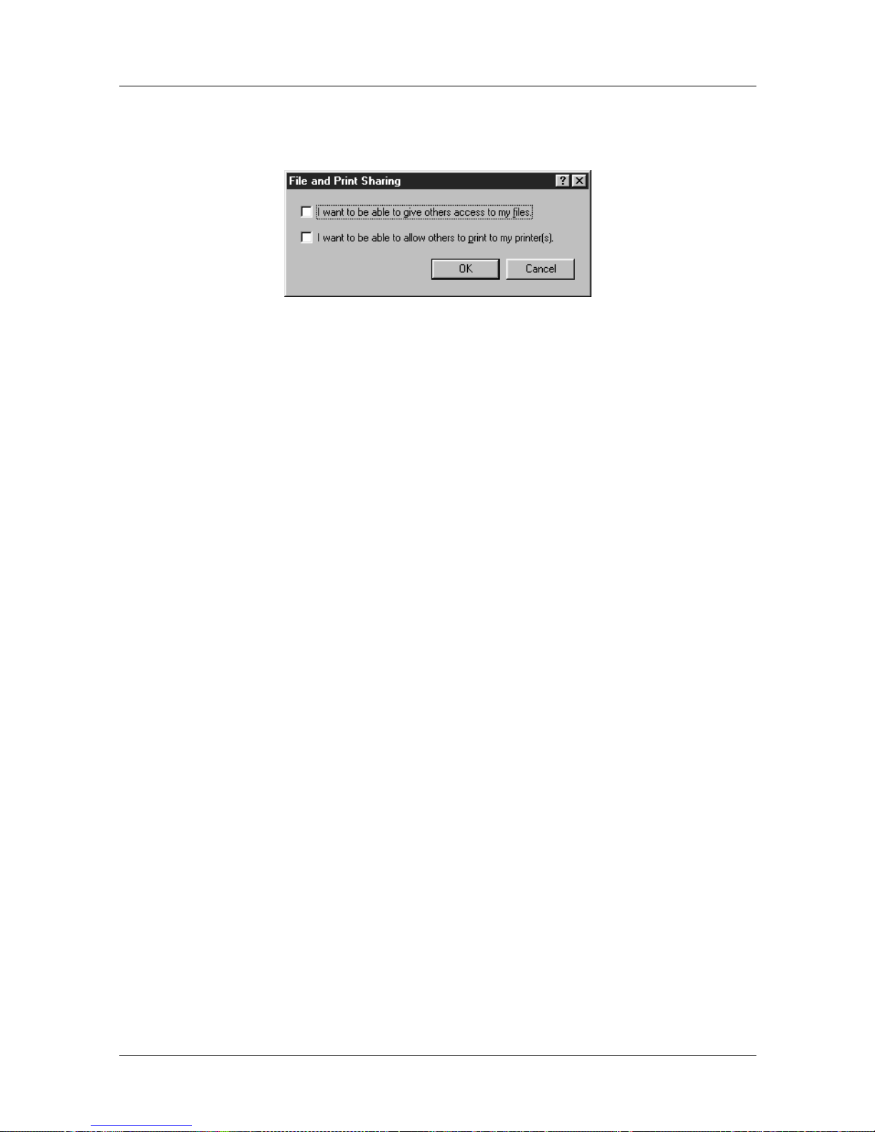
Nautica Configuration W izard Reference Gu ide
5. Deselect both options in the File and Print Sharing
window:
Figure 1-1. File and Print Sharing Window
6. Click on the OK button in the File and Print Sharing
window.
7. Click on OK in the Networks window.
8. Close down the Control Panel.
9. It may be necessary to reboot your PC at this time.
Graphical FTP Using “Keep Alive”
Traditionally FTP servers time out (or end) an FTP session if
there is no activity after a few minutes. Most command line FTP
clients take no steps to avoid this timeout. Some of the new
graphical FTP clients, howe v er , mak e frequent read (or ke epaliv e)
requests to keep the FTP sessions alive.
This option is fine for local network access and leased line
Internet browsing, but it can cause your remote ISDN connection
to stay up permanently.
If you use such FTP clients, be aware of this problem and close
down remote FTP co nnections once you have finished
transferring files.
1-4 118814-D Rev. 00
Page 43

Web Browsers
When you are browsing the web, many sites use “push”
technology. This feature opens a permanent channel between the
web site and your PC in order to update sound and graphic files
continuously. Using a remote router, such sites will keep your
ISDN connection open.
Other web sites cause your browser to refresh the screen at
regular intervals, for example, every 30 seconds. Again, this can
cause a link to stay open.
In order to minimize the effect of these data streams, do not leave
your PC unattended when it is in a web site and close down all
Internet connections when you have finished with them. When
browsing the web, be aware that ISDN calls are being made.
Menus and Basic Procedures
118814-D Rev. 00 1-5
Page 44
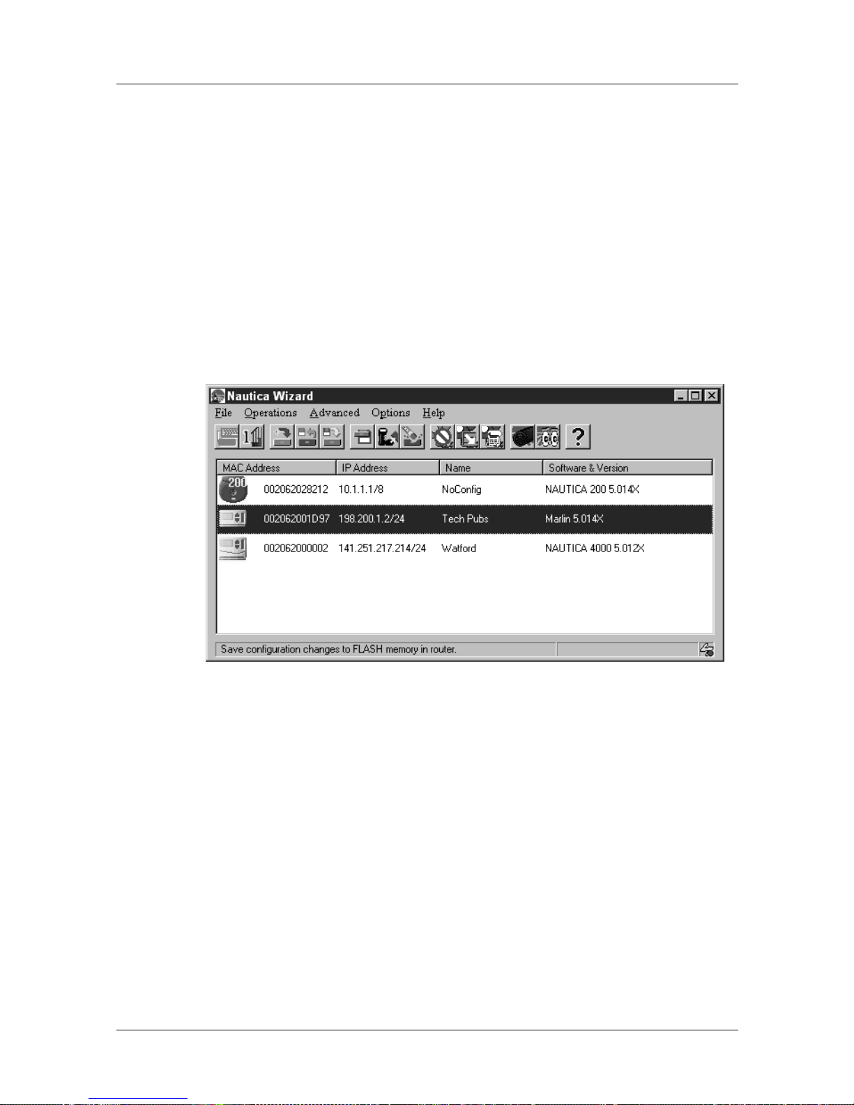
Nautica Configuration W izard Reference Gu ide
Initial Operations
As soon as the Installation Assis tant is complete, or the software
is opened, Nautica Wizard scans the local network and displays
all connected Nautica devices. The first router in the list is
automatically selected by Nautica Wizard, unless it finds an
unconfigured router, in which case this unit is selected.
Thereafter, the network is scanned every five seconds. Nautica
Wizard shows when it is sending out SNMP requests across the
local network by displaying a small yellow lightening bolt in the
bottom right of the Wizard window.
Figure 1-2. Nautica Wizard With SNMP Request Icon
If a device is found that has no conf i g urat i on , it is disp la yed as
blue in the window. To configure a unit using the Installation
Assistant, refer to the printed document “The Nautica Wizard
Installation Guide”.
1-6 118814-D Rev. 00
Page 45
Menus and Basic Procedures
The routers are shown in different colours depending on their
status:
Table 1-1. Router Colour Codes
Colour Status
Blue Unconfigured
Yellow Changes need to be saved
Green Router is stable
Grey Router is in bootm ode
The remainder of this chapter deals with procedures that can be
performed once a unit has been configured.
118814-D Rev. 00 1-7
Page 46
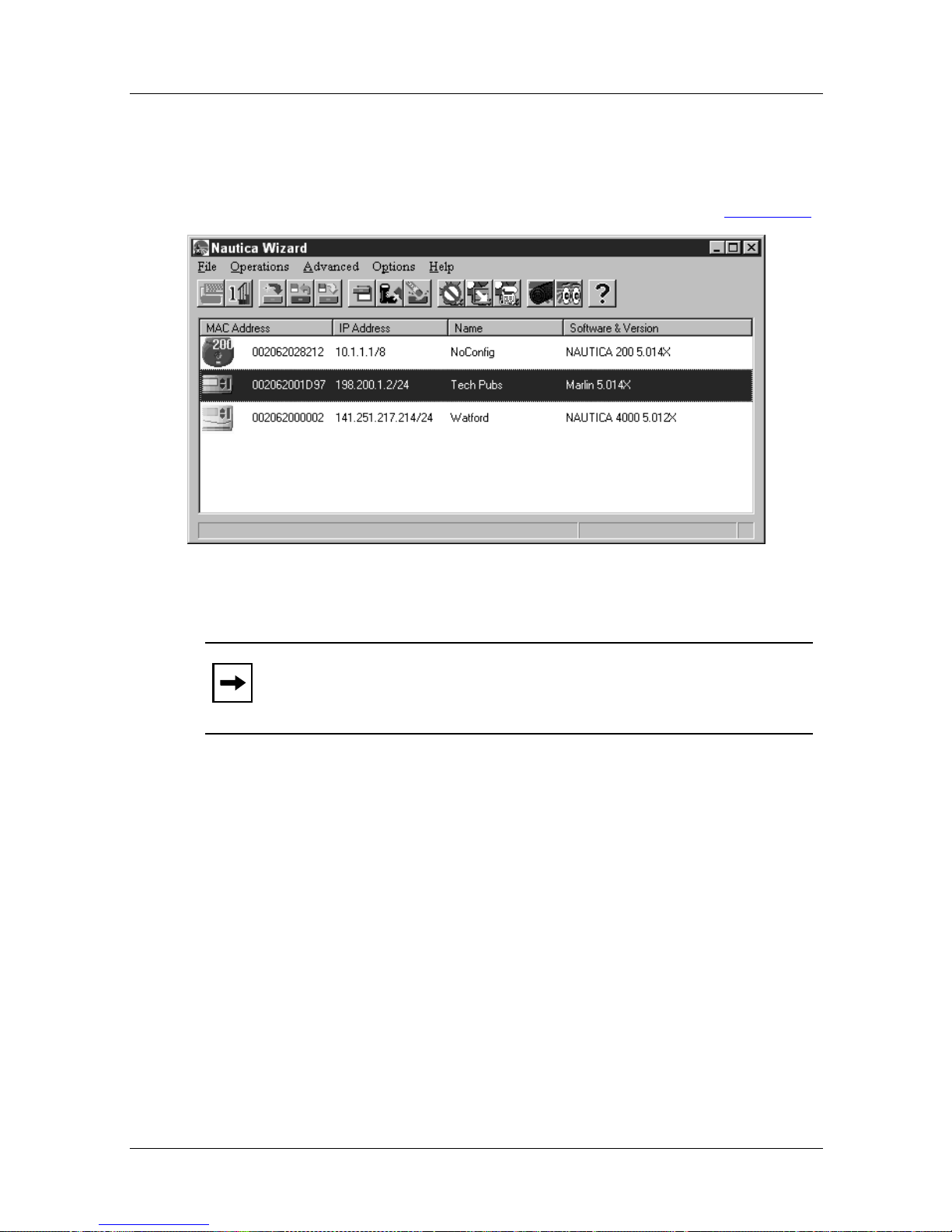
Nautica Configuration W izard Reference Gu ide
The Nautica Wizard Window
After Nautica Wizard has found all the connected Nautica
devices, the Nautica Wizard Window looks similar to Figure 1-3
.
Figure 1-3. Nautica Wizard Main Window
Note:
The Nautica Wizard window displays different icons for
the different Nautica products. To avoid confusion, some of the
icons also have the type of Nautica Router written on them.
To change the settings for a router, you select it by clicking on it
once. The router is highlighted and the menus in the menu bar of
the Nautica Wizard window become available.
Right click on an icon to bring up a quick menu of con figuration
options.
Nautica Wizard is designed to operate with the matching router
code. For example, version 5.01h of Nautica Wizard runs with
NauticaRS 5.001R.
The Nautica W izard wind o w sho ws the ver sion of router softw are
being run at the end of the router line. Check the Nautica Wizard
version by clicking on Help > About.
1-8 118814-D Rev. 00
Page 47
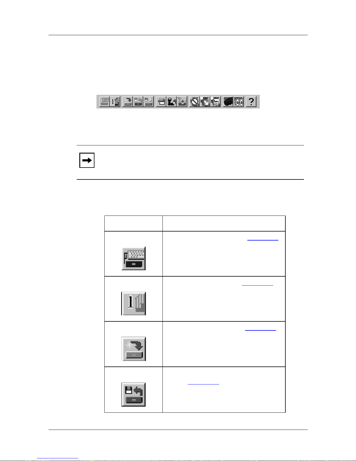
The Nautica Wizard Toolbar
Below the menu bar is the toolbar. The toolbar is a row of icons
that allows you to perform some menu commands rather than
choosing the comma nd itself from the relevant menu.
Figure 1-4. Nautica Wizard Tool bar
Menus and Basic Procedures
Note:
Most of the buttons in the toolbar only become available
if a router is selected in the main Nautica Wizard window.
The buttons are as follows:
Button Description
Run Installation Assistant (page 1-29)
One Step Configuration (page 1-30
)
118814-D Rev. 00 1-9
Download New Software (page 1-16
Save Router Configuration to a File
(*.ncf) (page 1-20)
)
Page 48
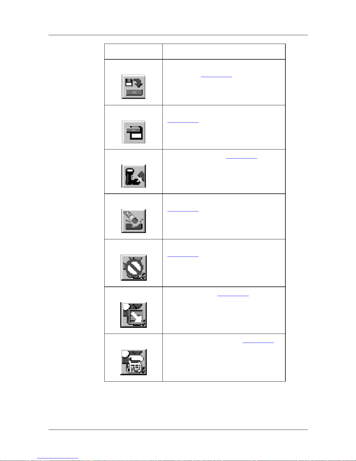
Nautica Configuration W izard Reference Gu ide
Button Description
Restore Router Configuration from a
File (*.ncf) (page 1-24)
Save Router Configuration on Router
(page 1-40
)
Reboot the Router (page 1-44
)
Erase the Router’s Configuration
(page 1-41
)
Enable/Disable Outgoing Data Calls
(page 1-12)
Autocall History (page 1-13
)
1-10 118814-D Rev. 00
Show ISDN Call History (page 1-14
)
Page 49
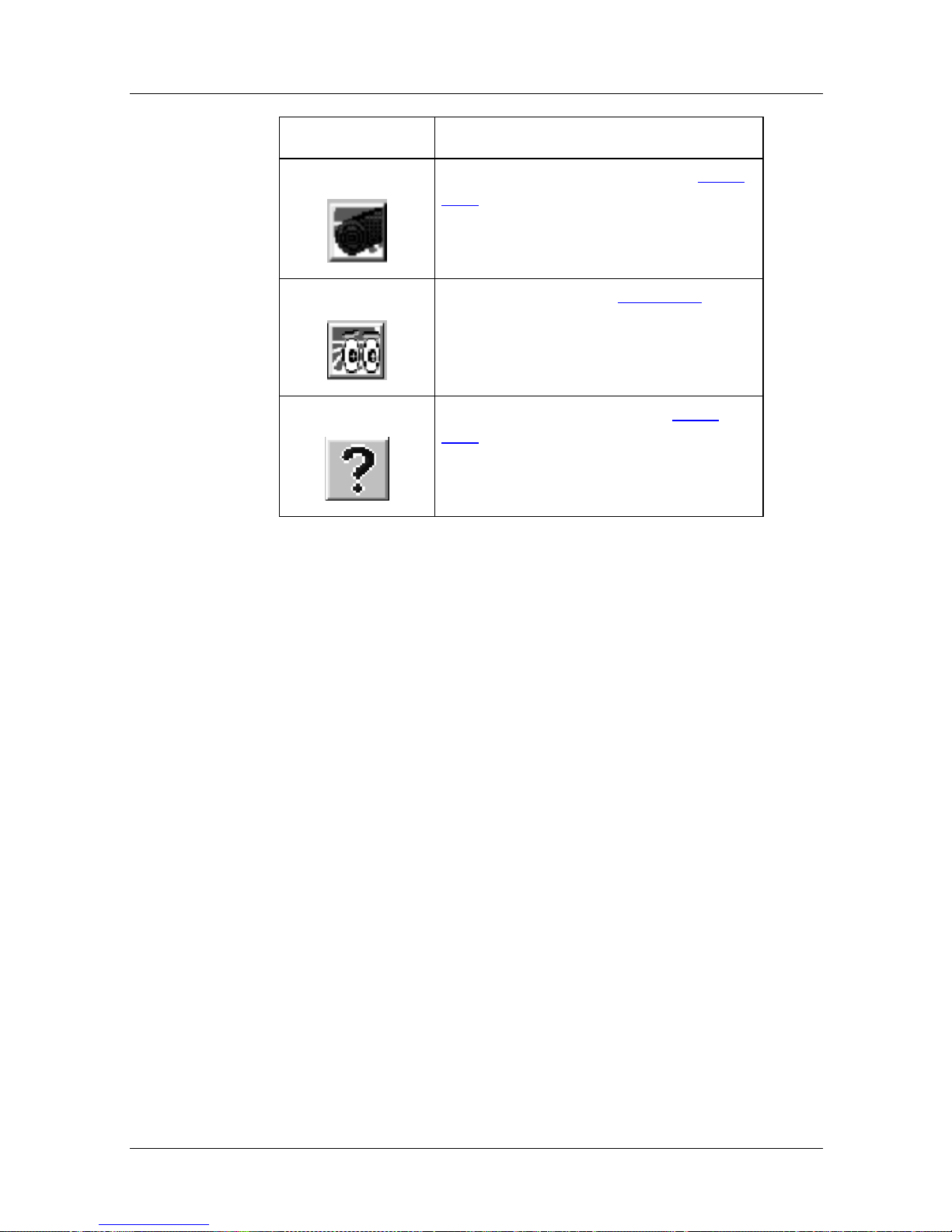
Button Description
Run the N autica Log Program (page
1-45)
Menus and Basic Procedures
Start Nautica Watch (page 1-47
)
Open Nautica Wizard Help (page
1-63)
Individual windows within Nautica Wizard have their own
buttons. These buttons are explained with the windows
throughout the rest of this reference guide.
118814-D Rev. 00 1-11
Page 50
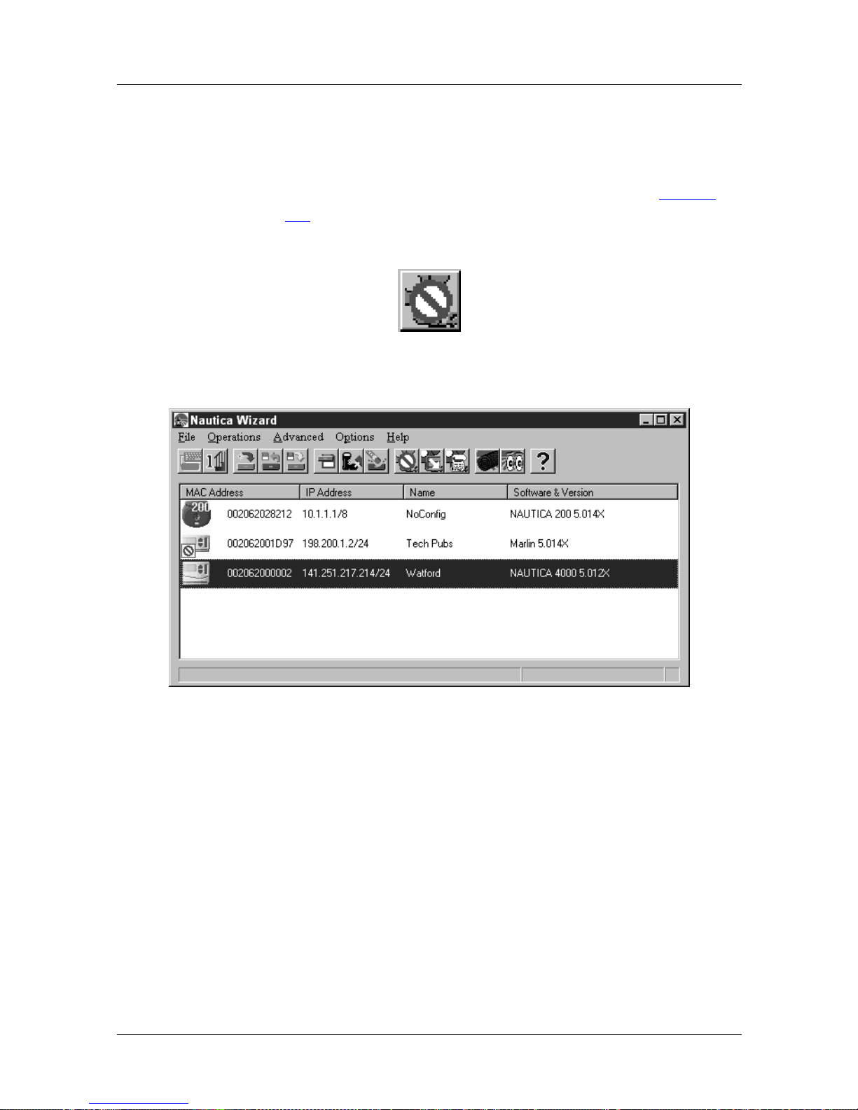
Nautica Configuration W izard Reference Gu ide
Enable/Disable ISDN Data Calls
To enable or disable ISDN data calls:
1. Select a router in the Nautica Wizard window (Figure
1-3).
2. Click on the Enable/Disable ISDN Data Calls button:
3. The router icon in the Nautica Wizard window displays a
No Entry sign:
Figure 1-5. Nautica Wizard with Data Calls Disabled
4. Select the router and click on the Enable/Disable ISDN
Data Calls button again to re-enable data calls on that
router .
1-12 118814-D Rev. 00
Page 51
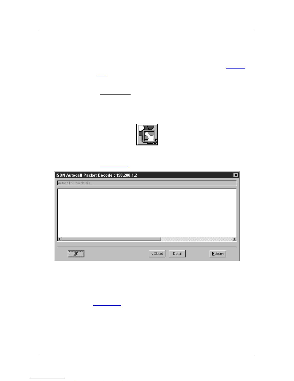
Autocall History
To display a list of the last ten autocalls:
1. Select a router in the Nautica Wizard window (Figure
1-3).
2. Clic k on Advanced > ISDN > Autocall History
(Chapter 10
OR
3. Click on the Autocall History button:
4. The ISDN Autocall Packet Decode window appears
(Figure 1-6
Menus and Basic Procedures
).
):
Figure 1-6. ISDN Autocall Packet Decode Window
For more information on this window and ISDN Autocalls, refer
to Chapter 10
118814-D Rev. 00 1-13
.
Page 52

Nautica Configuration W izard Reference Gu ide
Show ISDN Call History
To list all the ISDN calls made on your router:
1. Select a router in the Nautica Wizard window (Figure
1-3).
2. Clic k on Advanced > ISDN > Hist ory
Or
3. Click on the Show ISDN Call History button:
4. The ISDN Call History Table appears ( Figure 1-7
Figure 1-7. ISDN Call History Table
For more information on the ISDN Call History Table, refer to
Chapter 10
.
):
1-14 118814-D Rev. 00
Page 53
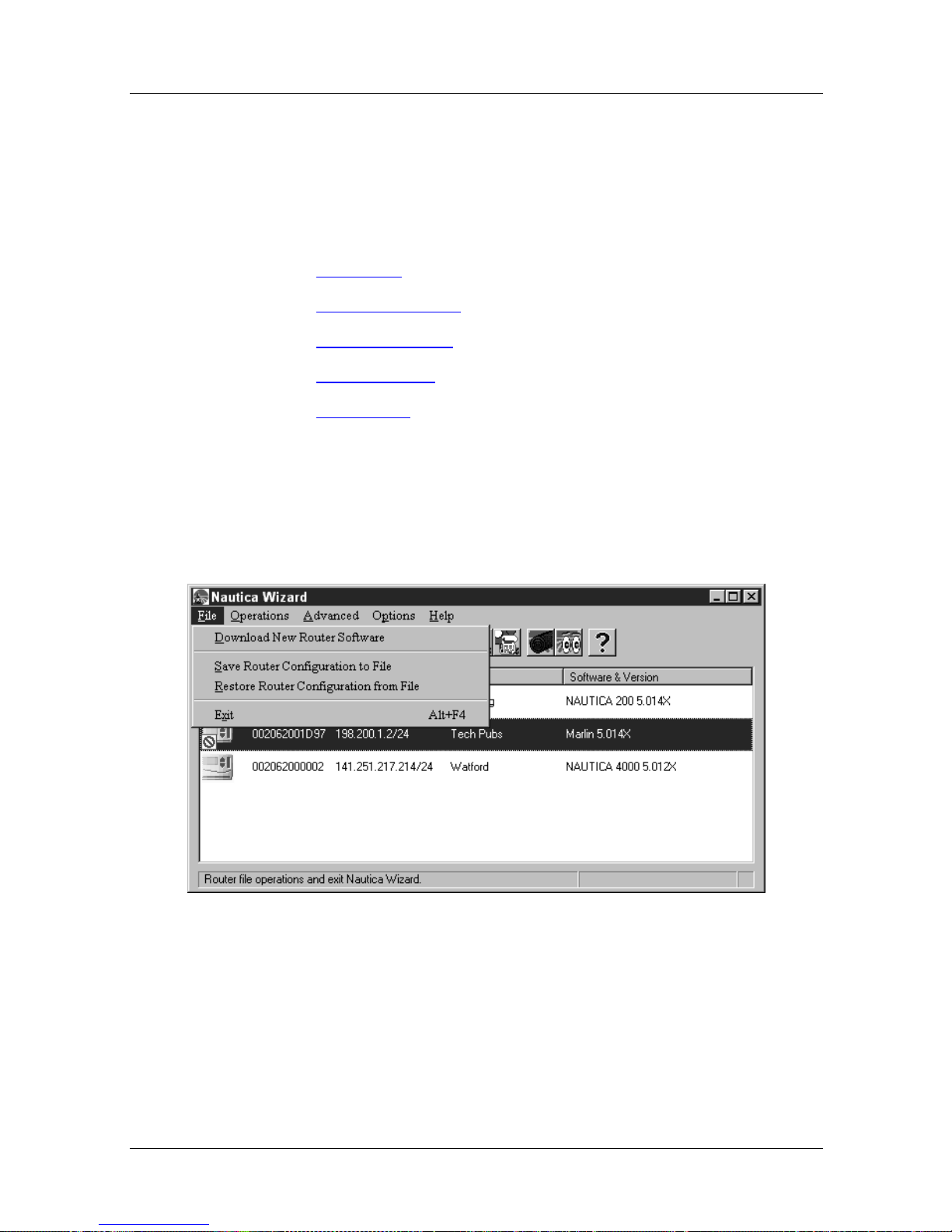
The Nautica Wizard Menus
The menus can be foun d at the top of the Naut ica W izard wi ndo w.
Click on the menu that contains the command in which you are
interested:
• File Menu
• Operations Menu
• Advanced Menu
• Options Menu
• Help Menu
File Menu
Menus and Basic Procedures
With a unit selected, the commands in the File menu are as
follows:
Figure 1-8. The Nautica Wizard File Menu
118814-D Rev. 00 1-15
Page 54
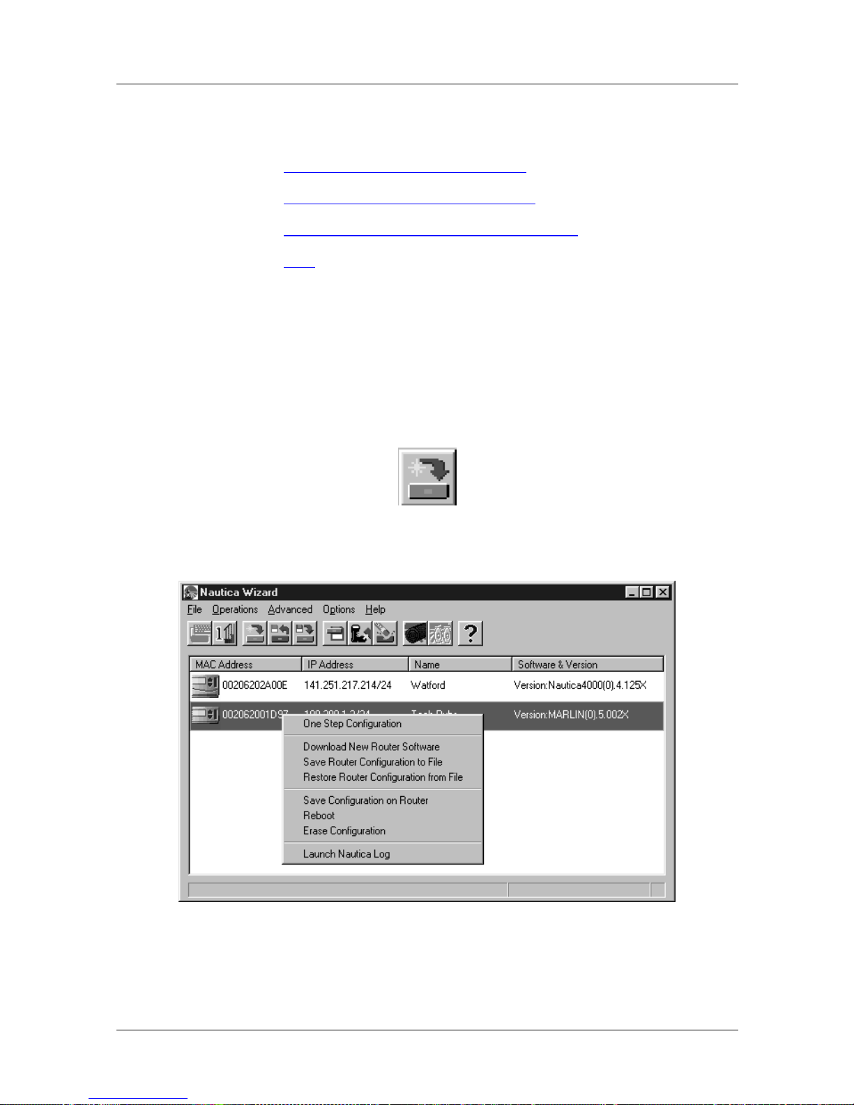
Nautica Configuration W izard Reference Gu ide
In the list below, click on the File menu command for which you
require further information.
• Download New Router Software
• Save Router Configuration to File
• Restore Router Configuration from File
• Exit
Download New Router Software
This command can be accessed with a unit selected and by:
• Clicking on File > Download New Router Software
• Clicking on the Download Software button in the toolbar:
• Right clicking on a router’s icon and selecting Download
New Router Software from the Quick menu:
Figure 1-9. The Nautica Wizard Quick Menu
1-16 118814-D Rev. 00
Page 55
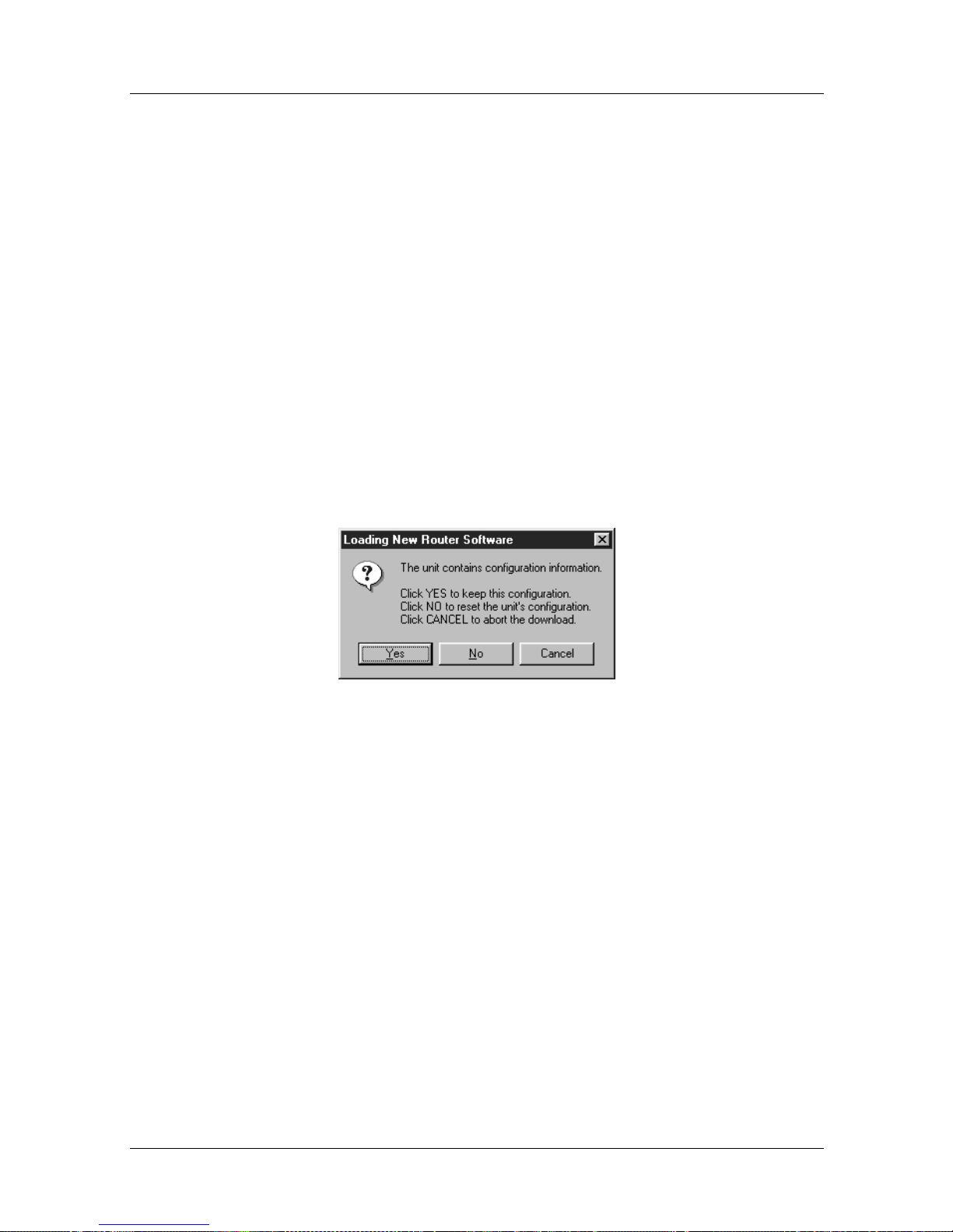
Menus and Basic Procedures
Downloading NauticaRS Software
As new versions of Nautica Wizard and BCC are released, they
are placed on the World Wide Web (WWW) for downloading.
The Uniform Resource Locator (URL) for this webs ite is:
http://support.baynetwor ks.com/software/router/nauticars.html
Download the new software file from this page (it is a self
extracting .exe file) and extract the file into a folder on your PC.
To load this new software onto your router, do the following:
1. In the Nautica Wizard window , click on the router to have
the new software.
2. Click on File > Download New Router Software. The
Downloading New Router Software window appears:
Figure 1-10. Downloading New Router Software
3. This window appears if the router already has a
configuration. Click on Ye s to have this configuration
saved and reloaded, click on No to have the configuration
erased (there is no undo), or click on Cancel to stop the
download.
118814-D Rev. 00 1-17
Page 56
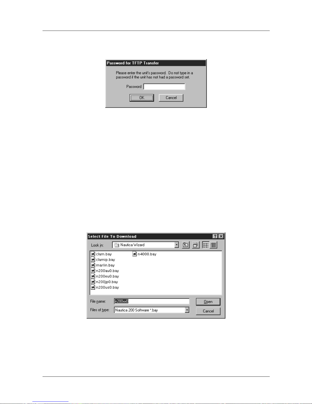
Nautica Configuration W izard Reference Gu ide
4. Clicking on Yes causes the Password for TFTP Transfer
window to appear:
Figure 1-11. Password for TFTP Transfer
5. Only enter a password here if the unit has a System
password (a password that needs to be entered every time
the router is configured).
6. Enter a password (if required) and click on OK. The
existing configuration of the router is now saved to a
temporary file using Trivial File Tr ansfer Protocol
(TFTP).
7. Once the configuration is sa ved (or discarded if y ou chose
No in the Downloading New Router Software window)
the Select a File to Download window appears:
Figure 1-12. Select a File to Download
1-18 118814-D Rev. 00
Page 57
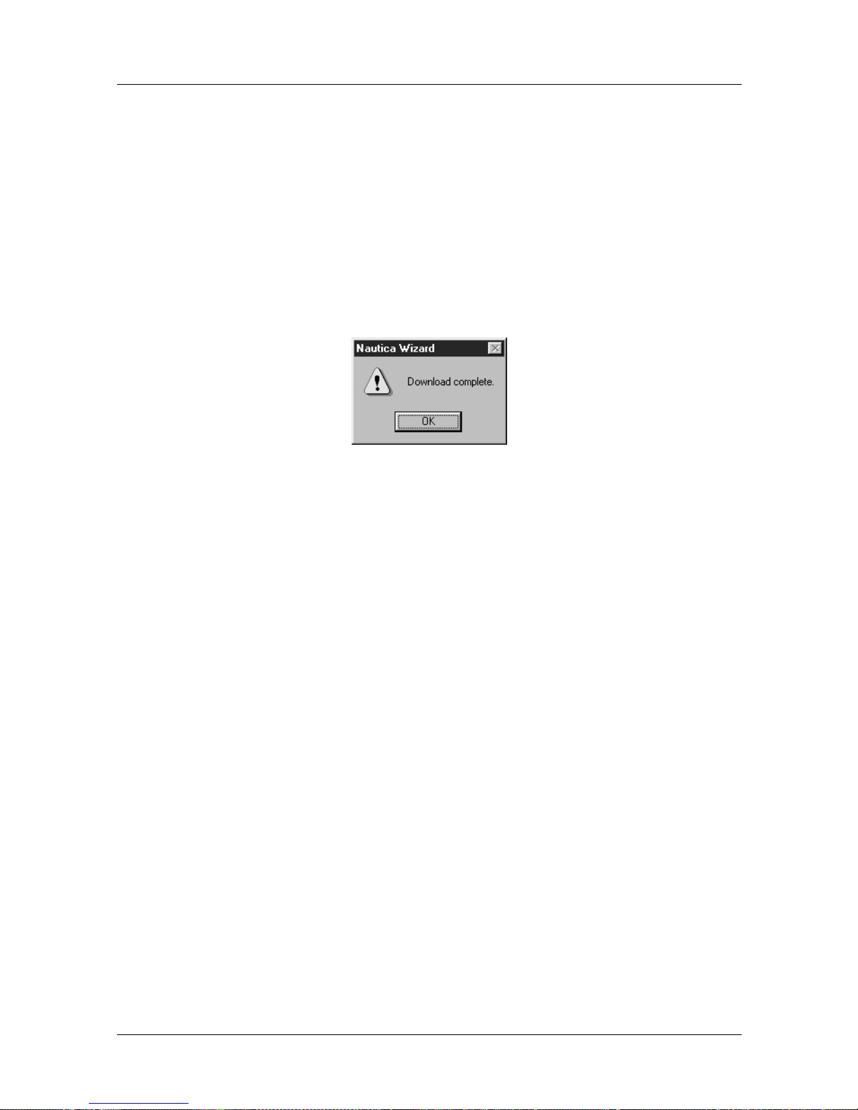
Menus and Basic Procedures
8. Find the file you downloaded from the website and
extracted. Click on this file and then click on the Open
button.
9. Nautica Wizard then downloads the file. The Status bar
at the bottom of the window shows what is ha ppening.
The configuration is erased, the software is downloaded
and the configuration is restored if you answered Yes in
the Downloading New Router Software window.
10. Once these steps are complete the final window appears:
Figure 1-13. Download Complete
Click on OK in this window and you are returned to Nautica
Wizard.
Downloading Nautica Wizard Software
When the Wizard itself is upgraded, do the following:
1. Download the new zip file from the website.
2. Place the zip file in the Nautica Wizard directory on your
PC.
3. Extract the file, overwriting any older versions.
118814-D Rev. 00 1-19
Page 58
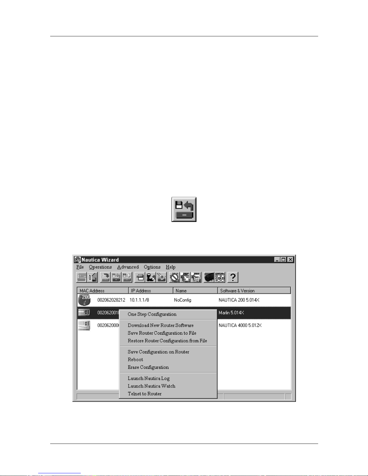
Nautica Configuration W izard Reference Gu ide
Save Router Configuration to File
Often, when you configure a router, you enter the same set of
parameters again and again. This can be very repetitive and
tedious if you have several routers to configure.
To make this task easier, it is possible to save the configuration
from one router into a file that can then be loaded into other
routers. This is achieved using Trivial File Transfer Protocol
(TFTP).
This command can be accessed with a unit selected and by:
• Clicking on File > Save Router Configuration to File
• Clicking on the Save Configuration to File button in the
toolbar:
• Right clicking on a router’s icon and selecting Save Router
Configuration to File from the Quick menu:
Figure 1-14. Nautica Wizard Quick Menu
1-20 118814-D Rev. 00
Page 59
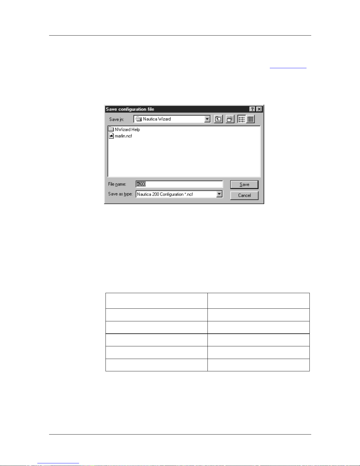
Menus and Basic Procedures
Saving the Configuration to a File
Once selected, the Save Configur ation File windo w (Figure 1 -15)
appears.
Figure 1-15. Save Configuration to File
1. Files are named automatica lly depending on the type of
Nautica router you are using. The file names are as
follows:
Table 1-2. Nautica Configuration File Names
Router File Name
Nautica 200 n200.ncf
Nautica CLAM clam.ncf
Nautica CLAM-IP clamip.ncf
Nautica Marlin marlin.ncf
Nautica 4000 n4000.ncf
It is only necessary to change these default names if you
plan to save many different configurations for the same
router type.
118814-D Rev. 00 1-21
Page 60
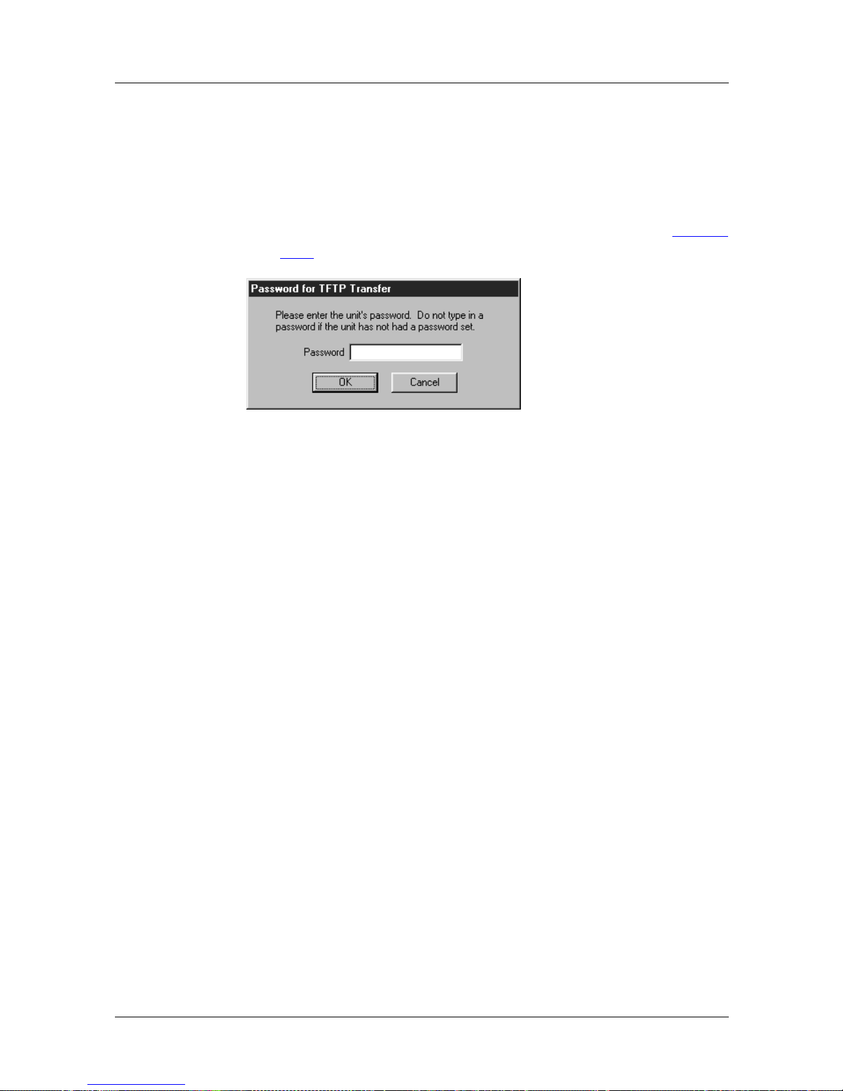
Nautica Configuration W izard Reference Gu ide
Nautica configuration files are given a .ncf exten s ion by
Nautica Wizard automatically. These files can also be
opened in a text editor, such as Notepad, for fast
amendment.
2. Once you have given the file a name, click on the Save
button. The Passw ord f or TFTP Transfer window (Figure
1-16) appears:
Figure 1-16. Password for TFTP Transfer
It is only necessary to enter a password here if you want
the file to be secure. The password has to be entered each
time the file is downloaded in future. Enter a password
and click on the OK button, or leave the password field
blank and click on O K.
1-22 118814-D Rev. 00
Page 61
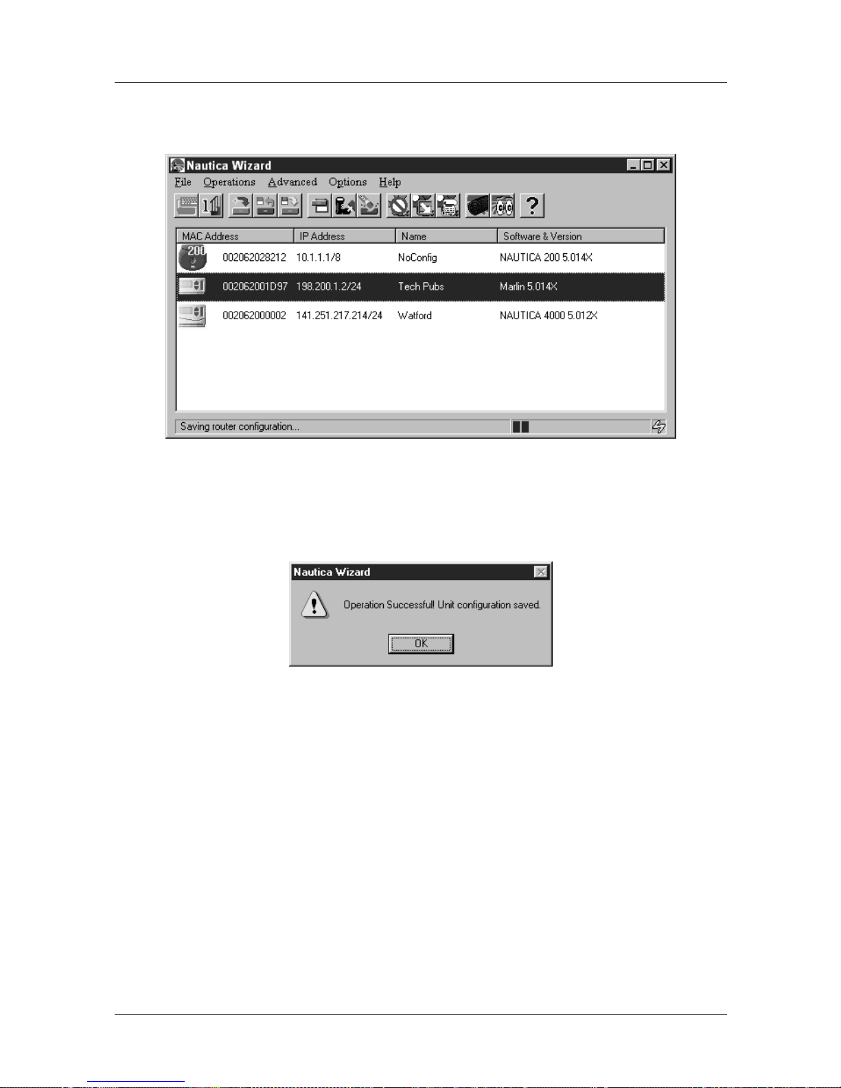
Menus and Basic Procedures
The configuration is saved to a f ile and y o u can see its
progress in the status bar of the Nautica Wizard menu:
Figure 1-17. Save Configuration Shown in Status Bar
3. Once the save is complete, the following window appears:
Figure 1-18. Operation Complete
Click on OK to end the operation.
118814-D Rev. 00 1-23
Page 62
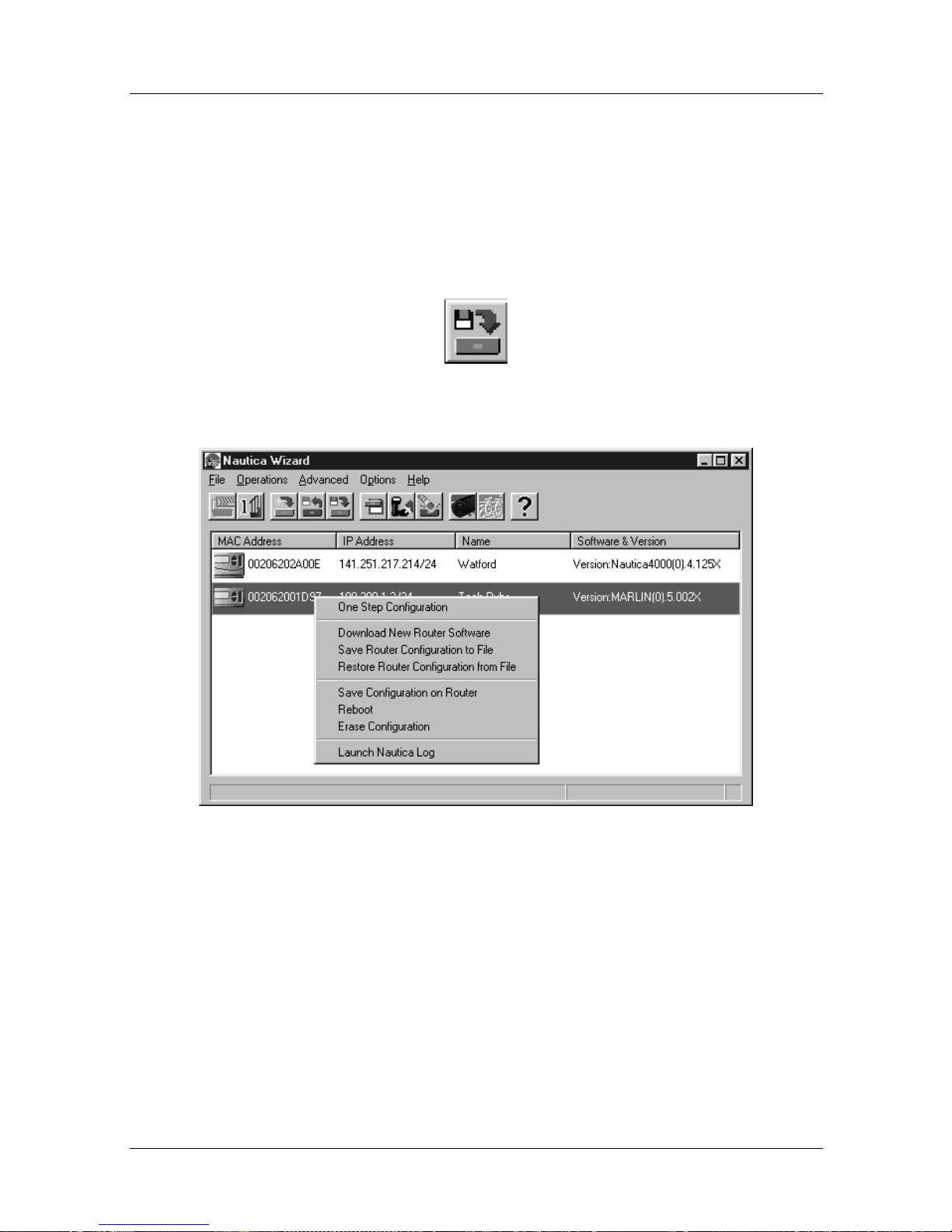
Nautica Configuration W izard Reference Gu ide
Restore Router Configuration from File
This command can be accessed with a unit selected and by:
• Clicking on File > Restore Router Configuration from File
• Clicking on the Restore Router Configuration button in the
toolbar:
• Right clicking on a rou ter’ s icon an d selecting R estore Router
Configuration from File from the Quick menu:
Figure 1-19. Nautica Wizard Quick Menu
Restoring the Configuration
To restore a configuration file to a router:
1. Click on the router that is to have the configuration.
2. Click on File > Restore Configuration from File.
1-24 118814-D Rev. 00
Page 63
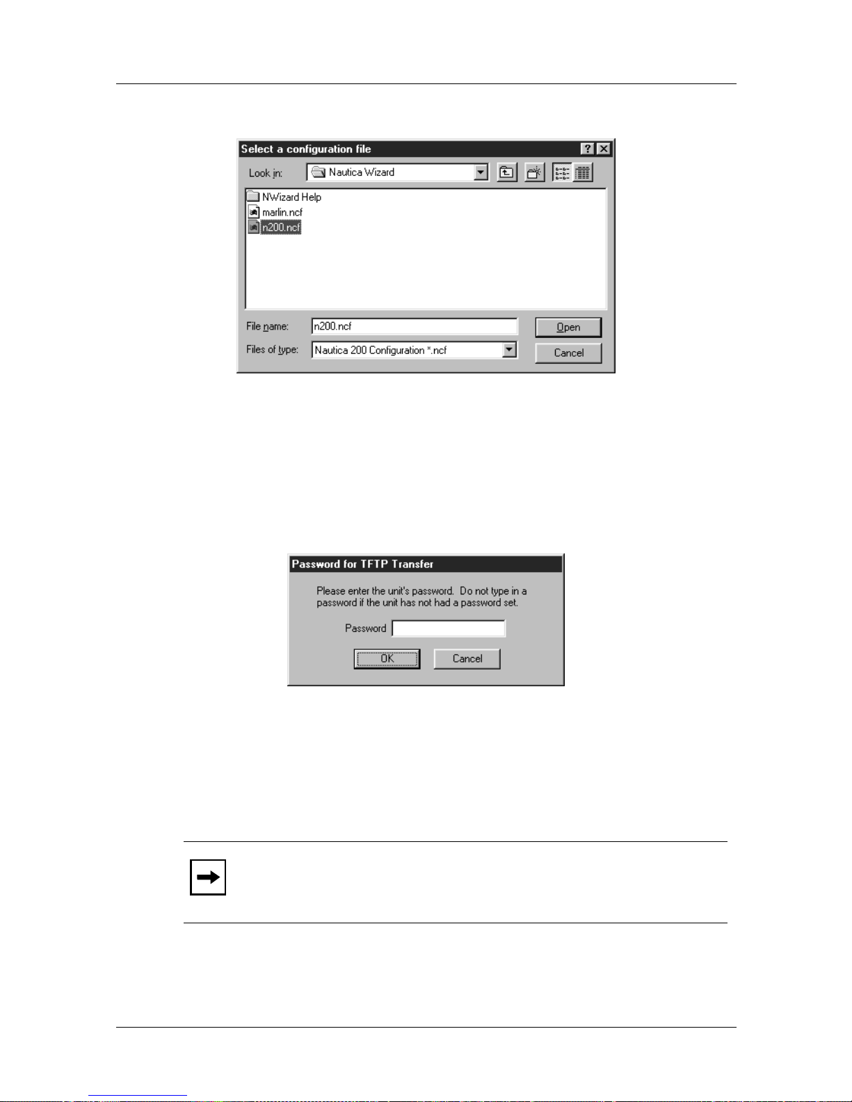
Menus and Basic Procedures
3. The Select a Configuration File window appears:
Figure 1-20. Select a Configuration File
4. Select the file that y ou sa ved ea rlier and click on the Open
button.
5. The Password for TFTP Transfer window appears:
Figure 1-21. Password for TFTP Transfer
6. Enter the current password for the unit. If the unit is in
default state no password is required.
Note:
118814-D Rev. 00 1-25
The password is set in the configuration file (if any).
Page 64
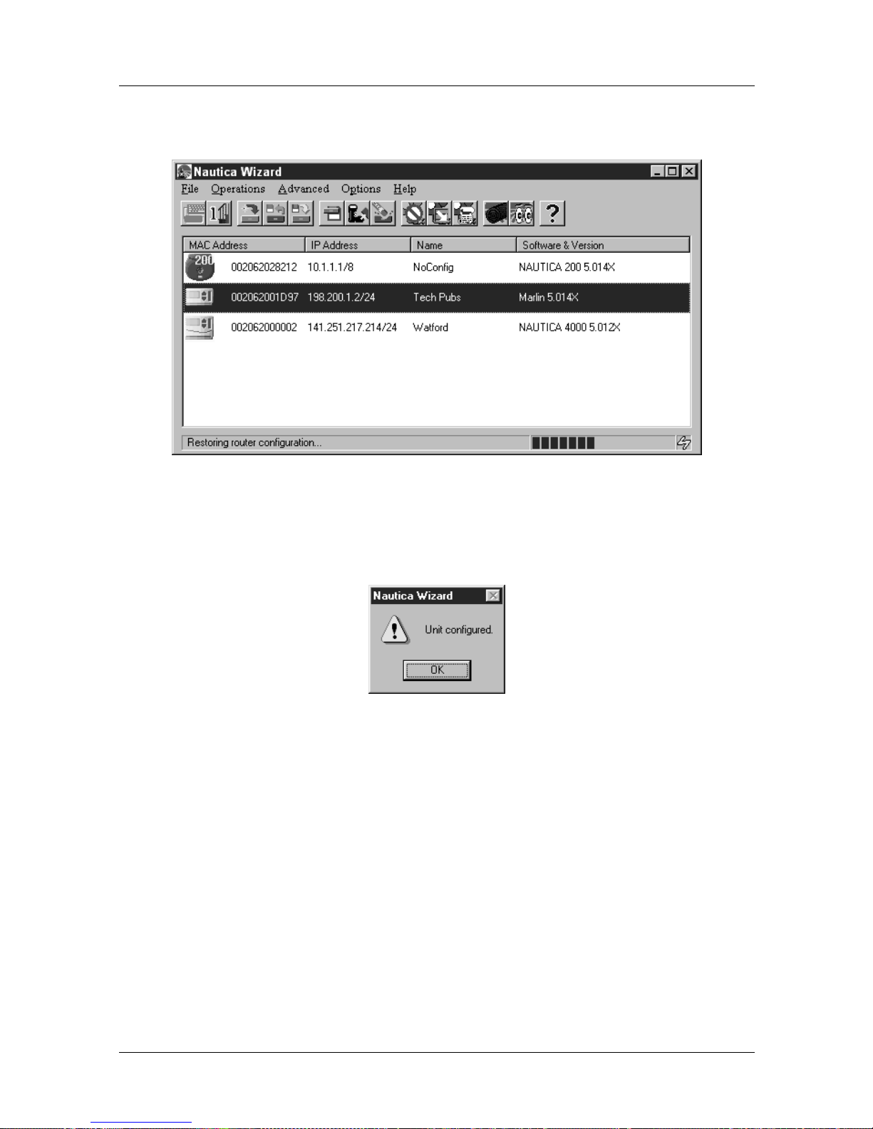
Nautica Configuration W izard Reference Gu ide
7. The transfer begins. You can see the progress in the
Status bar at the bottom of the Nautica Wizard window.
Figure 1-22. Nautica Wizard Configuration Restore
8. When the transfer is complete the final window appears:
Figure 1-23. Restore Complete
Click on OK and you are returned to Nautica Wizard.
1-26 118814-D Rev. 00
Page 65
Exit
Menus and Basic Procedures
To close Nautica Wizard:
• Click on File > Exit
• Press the [ALT] [F4] key
• Click on the Exit button on the right of the Nautica Wizard
Title bar
Note:
Closing Nautica Wizard does not turn the Nautica router
off; it just exits Nautica Wizard. Any operations the router is
performing carry on.
118814-D Rev. 00 1-27
Page 66
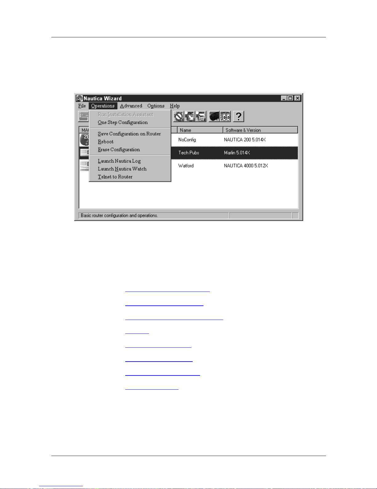
Nautica Configuration W izard Reference Gu ide
Operations Menu
With a unit selected, the comma nds in the Operations menu are as
follows:
Figure 1-24. The Nautica Wizard Operations Menu
In the list below, click on the command for which you require
help.
• Run Installatio n Assistant
• One Step Configuration
• Save Configuration on Router
• Reboot
• Erase Configuration
• Launch Nautica Log
• Launch Nautica Watch
• Telnet to Router
1-28 118814-D Rev. 00
Page 67
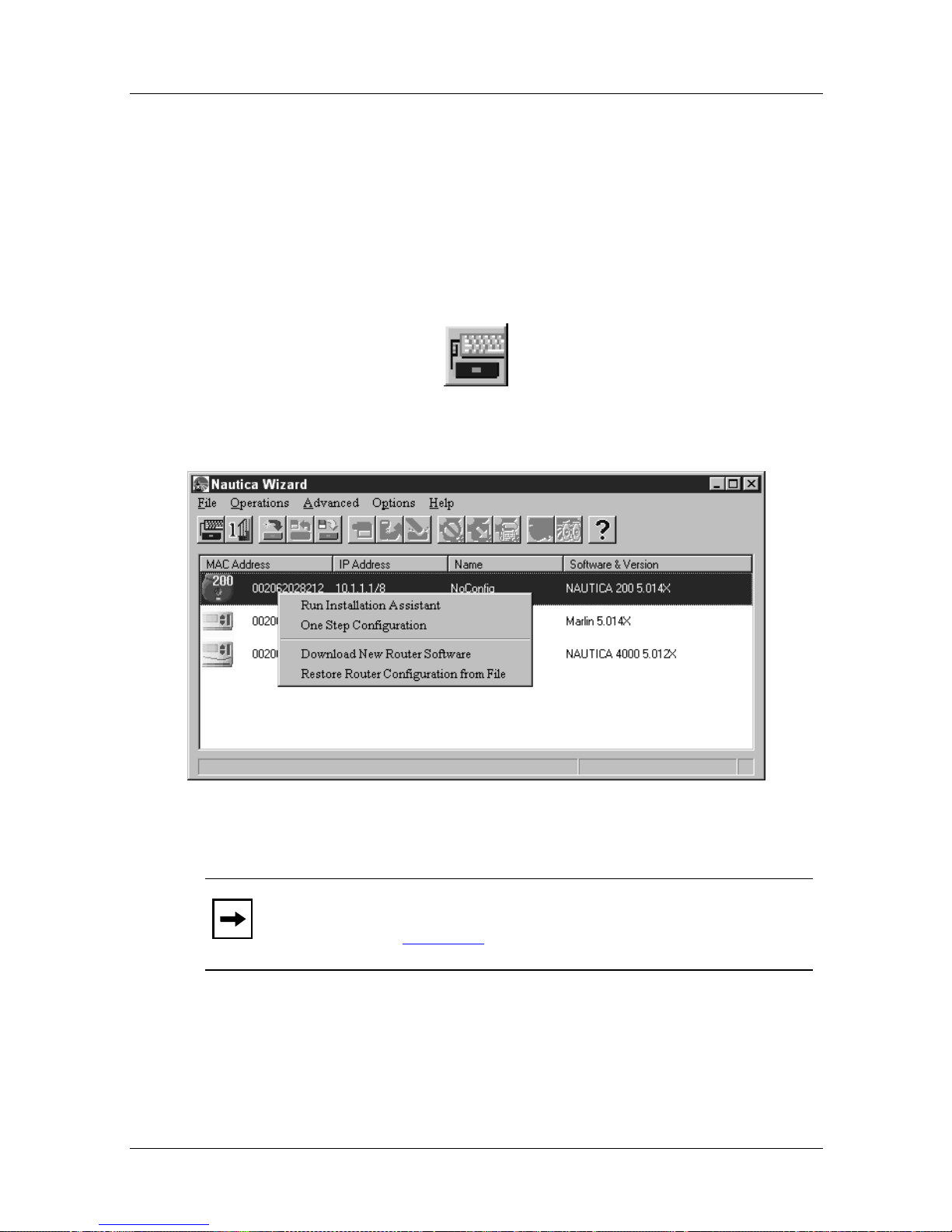
Run Installation Assistant
This command can be accessed with an unconfigured (blue) unit
selected and by:
• Clicking on Operations > Run Installation Assistant
• Clicking on the Run Installation Assistant button in the
toolbar:
• Right clicking on a router’s icon and selecting Run
Installation Assistant from the Quick m enu:
Menus and Basic Procedures
Figure 1-25. Nautica Wizard Quick Menu
Note:
configuration (page 1-41
For more information on the Installation Assistant, refer to the
printed document “The Nautica Wizard Installation Guide”.
118814-D Rev. 00 1-29
To set a unit back to its default state, erase the current
).
Page 68
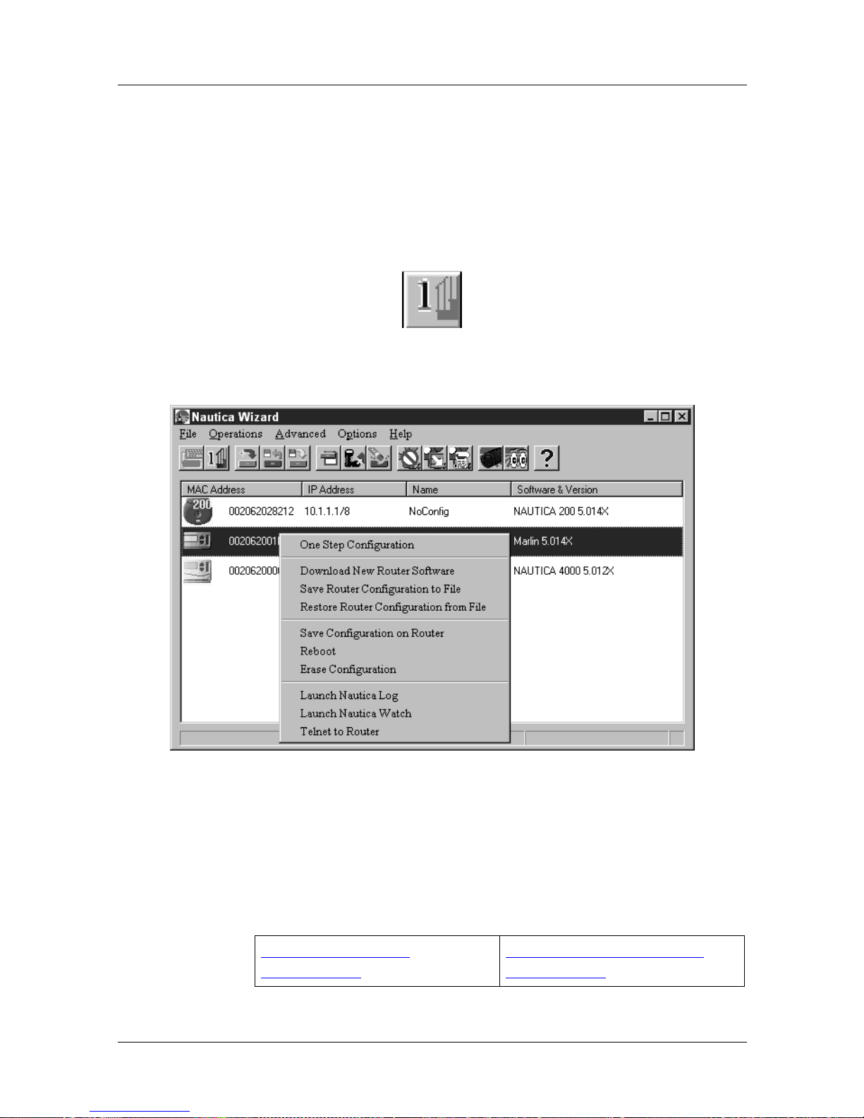
Nautica Configuration W izard Reference Gu ide
One Step Configuration
This command is designed for more advanced users and can be
accessed with a unit selected and by:
• Clicking on Operations > One Step Configuration
• Clicking on the One Step Configuration button in the toolbar:
• Right clicking on a router’s icon and selecting One Step
Configuration from the Quick menu:
Figure 1-26. Nautica Wizard Quick Menu
One Step Configuration allows you to quickly configure, or
amend, the main features of a router. In the table below, select the
configuration option for which you require further assistance.
Standard One Step
Configuration
1-30 118814-D Rev. 00
North American One Step
Configuration
Page 69
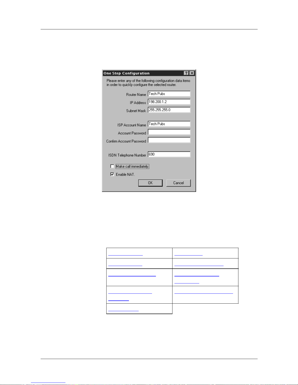
Menus and Basic Procedures
Standard One Step Configuration
Selecting the One Step Configuration command causes the One
Step Configuration window to appear:
Figure 1-27. One Step Configuration Window
In the table below, click on the parameter for whic h you require
further assistance.
Router Name IP Address
Subnet Mask ISP Account Name
Account Password Confirm Account
Password
ISDN Telephone
Number
Enable NAT
Make Call Immediately
118814-D Rev. 00 1-31
Page 70

Nautica Configuration W izard Reference Gu ide
Parameter: Router Name
Function: A name assig ned to the route r.
Instructions: Enter a name by which to recognise the router in the
Nautica Wizard window.
Parameter: IP Address
Function: The IP address of the router.
Instructions: Enter a valid IP address for the router.
Parameter: Subnet Mask
Function: A subnet mask to be used with the IP address.
Instructions: Enter the subnet mask to be used with the router IP
address.
Parameter: ISP Account Name
Function: The account name supplied by the Internet Service
Provider (ISP) or Intranet Manager.
Instructions: Enter any account name you have been given.
Parameter: Account Password
Function: A password used when connecting with the ISP or
corporate intranet.
Instructions: Enter a password (if supplied). The password does not
appear on the screen for security purposes.
Note: All passwords are case sensitive.
1-32 118814-D Rev. 00
Page 71
Menus and Basic Procedures
Parameter: Confirm Account Password
Function: Confirms that the password has been entered correctly
into the Account password field.
Instructions: Re-enter the password.
Note: All passwords are case sensitive.
Parameter: ISDN Telephone Nu mber
Function: The ISDN telephone number that connects you to the
ISP or corporate intranet.
Instructions: Enter an ISDN telephone number.
Parameter: Make Call Immediately
Function: Immediately calls the ISDN telephone number entered
into the ISDN Telephone Number field.
Instructions: Check this option if you want to call the ISP or intranet
immediately the One Step Configuration window closes.
Note: The Make Call Immediately field is on ly visible when an
ISDN telephone number has been entered.
Parameter: Enable NAT
Function: Allows Network Address Translation (NAT) to operate.
Instructions: Check this option if you want to use NAT. For more
information on NAT, refer to Chapter 17
.
118814-D Rev. 00 1-33
Page 72
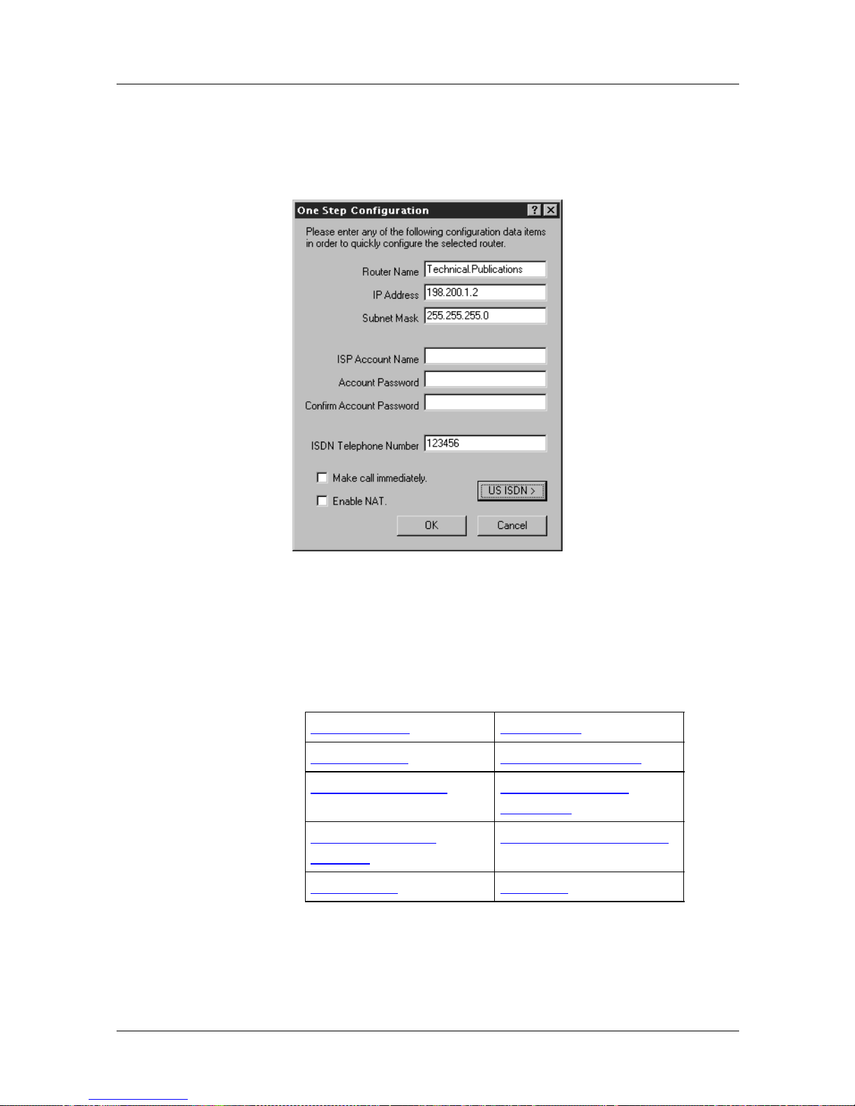
Nautica Configuration W izard Reference Gu ide
North American One Step Configuration
Selecting the One Step Configuration command causes the One
Step Configuration window to appear:
Figure 1-28. North American One Step Configuration Window
In the table below, click on the option for which you require
further assistance.
Router Name IP Address
Subnet Mask ISP Account Name
Account Password Confirm Account
Password
ISDN Telephone
Number
Enable NAT US ISDN
Make Call Immediately
1-34 118814-D Rev. 00
Page 73

Menus and Basic Procedures
Parameter: Router Name
Function: A name assig ned to the route r.
Instructions: Enter a name by which to recognise the router in the
Nautica Wizard window.
Parameter: IP Address
Function: The IP address of the router.
Instructions: Enter a valid IP address for the router.
Parameter: Subnet Mask
Function: A subnet mask to be used with the IP address.
Instructions: Enter the subnet mask to be used with the router IP
address.
Parameter: ISP Account Name
Function: The account name supplied by the Internet Service
Provider (ISP) or Intranet Manager.
Instructions: Enter any account name you have been given.
Parameter: Account Password
Function: A password used when connecting with the ISP or
corporate intranet.
Instructions: Enter a password (if supplied). The password does not
appear on the screen for security purposes.
Note: All passwords are case sensitive.
118814-D Rev. 00 1-35
Page 74
Nautica Configuration W izard Reference Gu ide
Parameter: Confirm Account Password
Function: Confirms that the password has been entered correctly
into the Account password field.
Instructions: Re-enter the password.
Note: All passwords are case sensitive.
Parameter: ISDN Telephone Nu mber
Function: The ISDN telephone number that connects you to the
ISP or corporate intranet.
Instructions: Enter an ISDN telephone number.
Parameter: Make Call Immediately
Function: Immediately calls the ISDN telephone number entered
into the ISDN Telephone Number field.
Instructions: Check this option if you want to call the ISP or intranet
immediately the One Step Configuration window closes.
Note: the Make Call Immediately field is only visible when an
ISDN T e lephon e number has been entered.
Parameter: Enable NAT
Function: Allows Network Address Translation (NAT) to operate.
Instructions: Check this option if you want to use NAT. For more
1-36 118814-D Rev. 00
information on NAT, refer to Chapter 17
.
Page 75
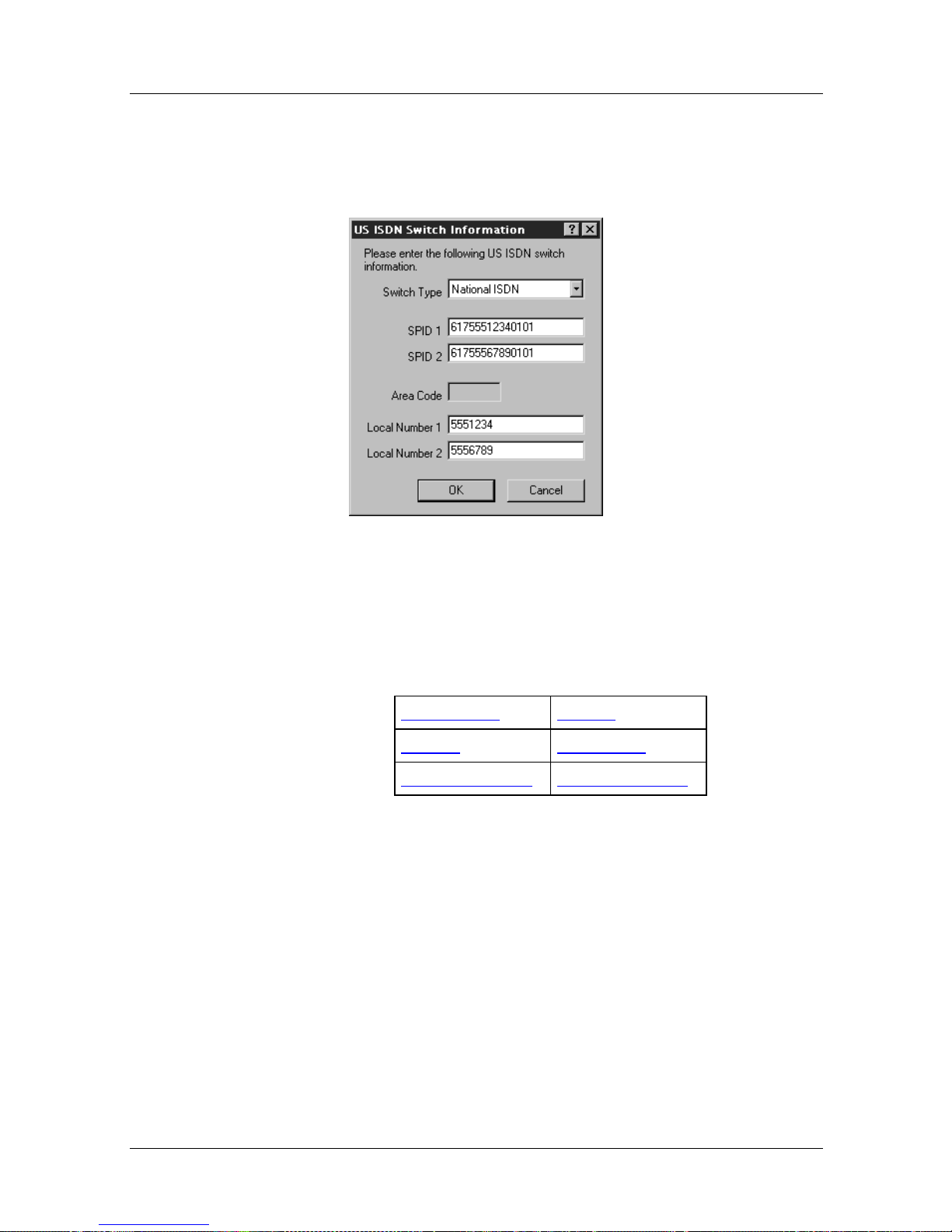
Parameter: US ISDN
Clicking on the US ISDN button causes the US ISDN Switch
Information window to appear:
Menus and Basic Procedures
Figure 1-29. US ISDN Switch Information Window
In the table below, click on the parameter for whic h you require
further assistance.
Switch Type SPID 1
SPID 2 Area Code
Local Number 1 Local Number 2
118814-D Rev. 00 1-37
Page 76
Nautica Configuration W izard Reference Gu ide
Parameter: Switch Type
Function: The switch type is the type of ISDN line you are
operating. The default setting here is National ISDN,
but other values such as AT&T Custom Point to Point,
AT&T Custom Multipoint and Nortel DMS Custom can
also be selected.
Instructions: Select the ISDN line type. This information is supplied
by your telephone company. If you are unsure of the
switch type, select the Autose nse option.
Note: Selecting Autosense disables the two SPID fields.
Parameter: SPID 1
Function: Service Profile Identifiers (SPIDs) are provided by your
telephone company. If your switch type is AT&T
Custom Point to Point, you do not have to enter a SPID.
For all other line types there should be a SPID
corresponding to each local ISDN telephone number.
Instructions: Enter any SPID provided by your telephone company.
Parameter: SPID 2
Function: Service Profile Identifiers (SPIDs) are provided by your
telephone company. If your switch type is AT&T
Custom Point to Point, you do not have to enter a SPID.
For all other line types there should be a SPID
corresponding to each local ISDN telephone number.
Instructions: Enter any SPID provided by your telephone company.
1-38 118814-D Rev. 00
Page 77

Menus and Basic Procedures
Parameter: Area Code
Function: The local telephone area code.
Instructions: Enter the area code for your location.
Parameter: Local Number 1
Function: Local numbers are provi ded by your tel ephone compan y .
If your switch type is AT&T Custom Point to Point, you
do not have to enter a local number.
Instructions: Enter any local numbers provided by your telephone
company.
Parameter: Local Number 2
Function: Local numbers are provi ded by your tel ephone compan y .
If your switch type is AT&T Custom Point to Point, you
do not have to enter a local number.
Instructions: Enter any local numbers provided by your telephone
company.
118814-D Rev. 00 1-39
Page 78
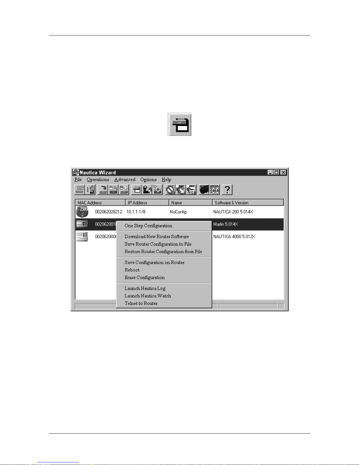
Nautica Configuration W izard Reference Gu ide
Save Configuration on Router
This command can be accessed with a unit selected and by:
• Clicking on Operations > Save Configuration on Router
• Clicking on the Save Configuration on Router button in the
toolbar:
• Right clicking on a router’s icon and selecting Save
Configuration on Router from the Quick menu:
Figure 1-30. Nautica Wizard Quick Menu
When you make changes to the configuration of a router, the
router colour changes to yellow in the Nautica Wizard window.
To save the changes you have made:
1. Click on the router to be saved.
2. Choose Operations > Save Configuration on Router.
1-40 118814-D Rev. 00
Page 79
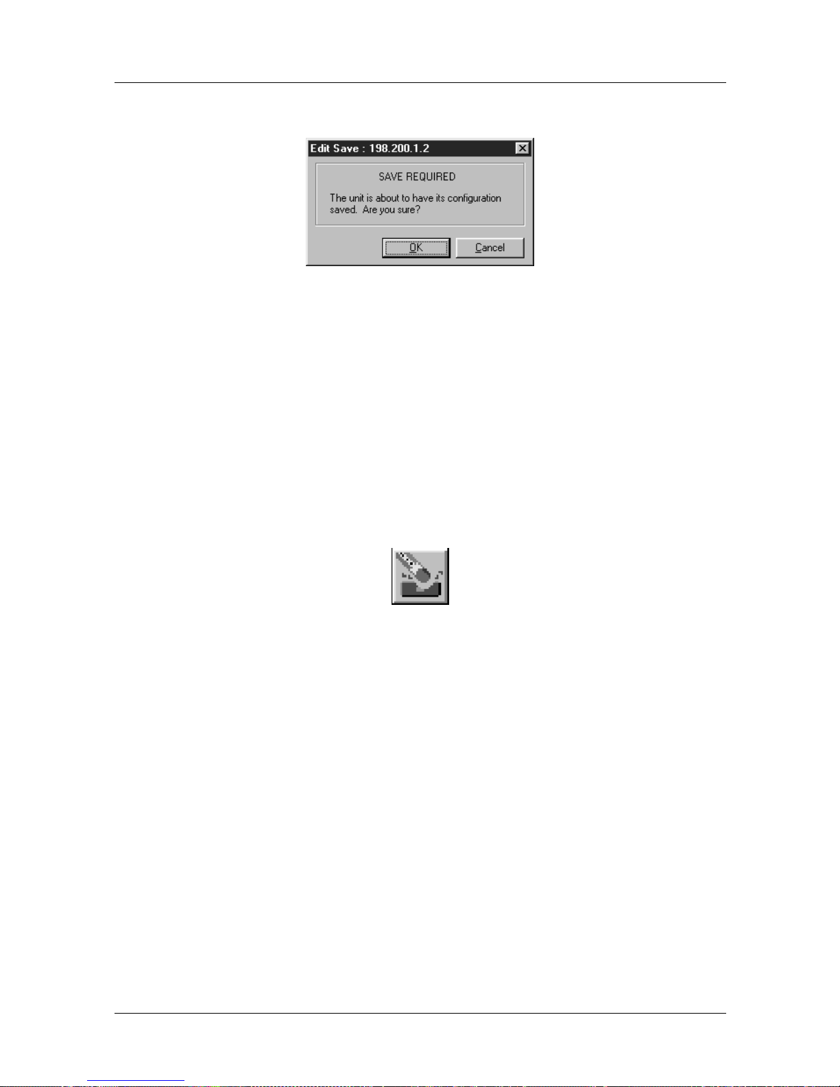
3. The Edit Save window appears:
Figure 1-31. Edit Save
4. Click on OK and the configuration change s are saved.
Erase Configuration
Menus and Basic Procedures
This command can be accessed with a unit selected and by:
• Clicking on Operations > Erase Configuration
• Clicking on the Erase Configuration button in the toolbar:
• Right clicking on a router’s icon and selecting Erase
Configuration from the Quick menu:
118814-D Rev. 00 1-41
Page 80
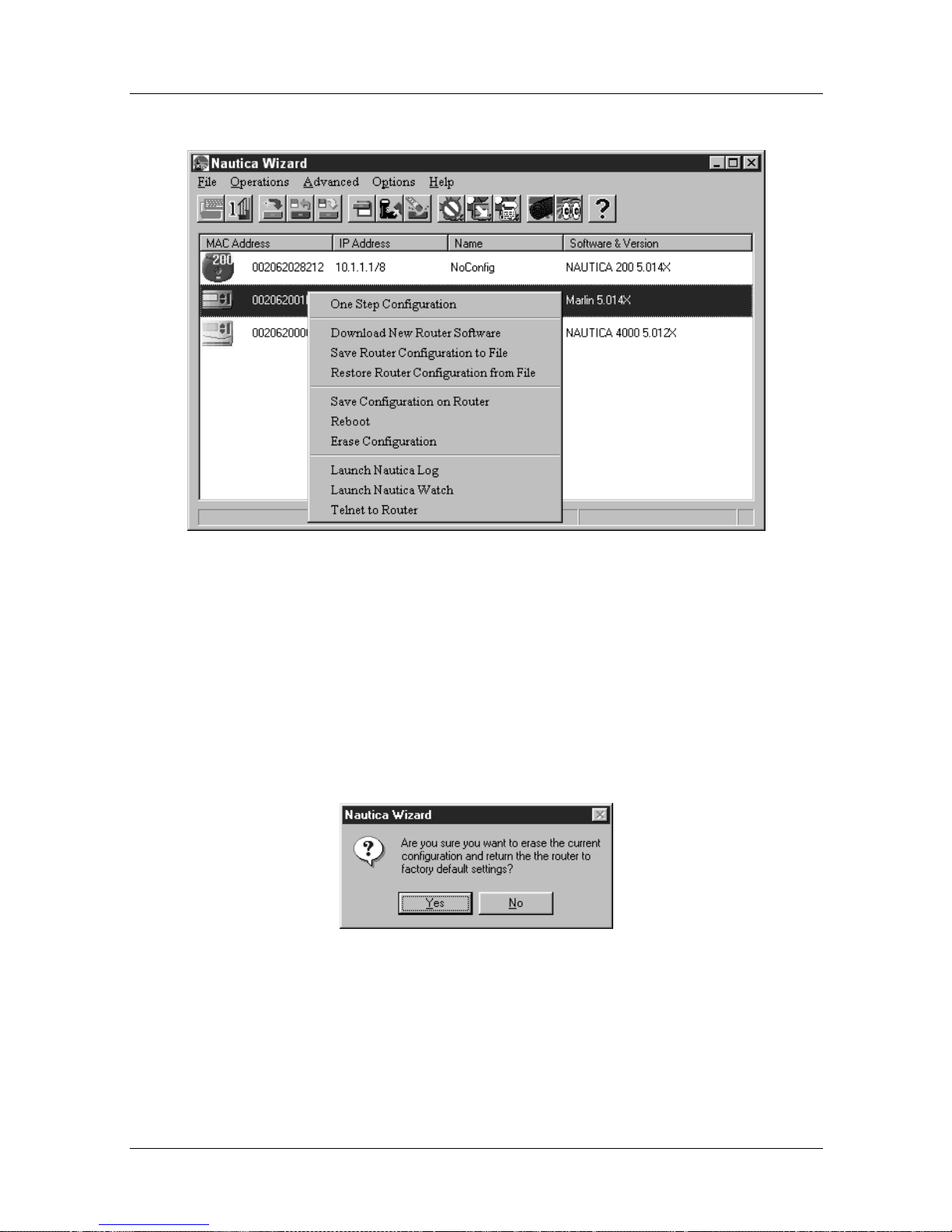
Nautica Configuration W izard Reference Gu ide
Figure 1-32. Nautica Wizard Quick Menu
To erase a unit’s configuration and set all the parameters back to
the default settings:
1. Click on the unit to have its configuration erased.
2. Click on Operations > Erase Configuration.
3. A warning window appears:
Figure 1-33. Erase Warning
4. Click on Yes to complete the Erase, or No to cancel.
1-42 118814-D Rev. 00
Page 81
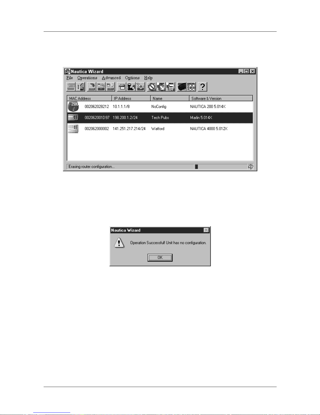
Menus and Basic Procedures
5. If you choose Yes, the configuration is erased. You can see
the progress of this action in the Status bar at the bottom
of the Nautica Wizard window.
Figure 1-34. Nautica Wizard with Erase Configuration
6. When this action is completed, the confirmation window
appears:
Figure 1-35. Erase Complete
7. Click on OK to end the task.
118814-D Rev. 00 1-43
Page 82
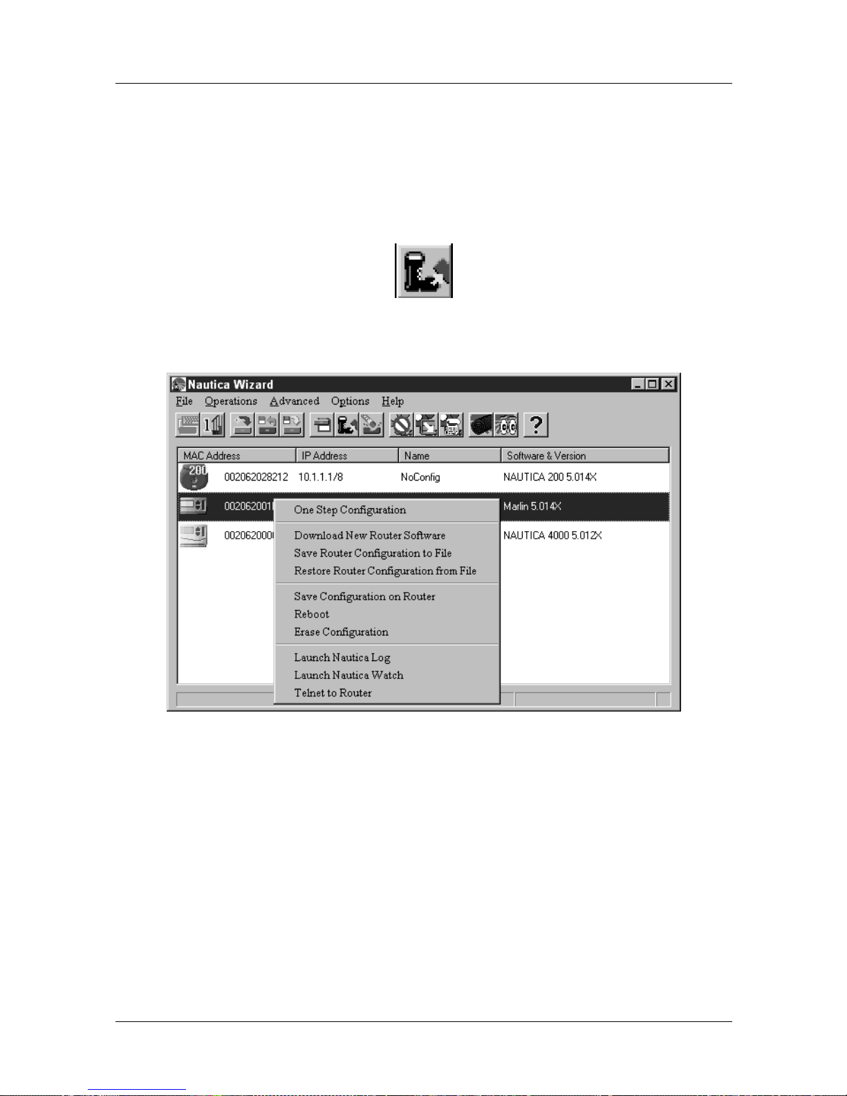
Nautica Configuration W izard Reference Gu ide
Reboot
This command can be accessed with a unit selected and by:
• Clicking on Operations > Reboot
• Clicking on the Reboot button in the toolbar:
• Right clicking on a router’s icon and selecting Reboot from
the Quick menu:
Figure 1-36. Nautica Wizard Quick Menu
Rebooting the router returns it to the condition it was in at the last
save. Any unsaved changes made to the unit’s configuration are
lost at the time of rebooting.
To reboot the router:
1. Click on the unit to be rebooted in the Nautica Wizard
window.
2. Click on Operations > Reboot.
1-44 118814-D Rev. 00
Page 83
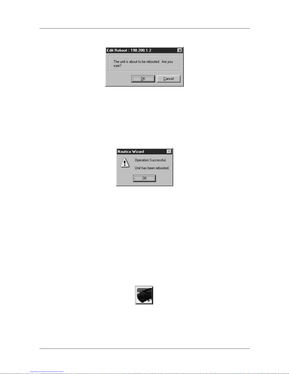
Menus and Basic Procedures
3. The Edit Reboot window appears:
Figure 1-37. Edit Reboot
4. Click on OK to reboot the router or Cancel to end the
action.
5. After the reboot, the confirmation window appears:
Figure 1-38. Reboot Confirmation
Click on OK and the action is completed.
Launch Nautica Log
This command can be accessed with a unit selected and by:
• Clicking on Operations > Launch Nautica Log
• Clicking on the Nautica Log button in the toolbar:
118814-D Rev. 00 1-45
Page 84
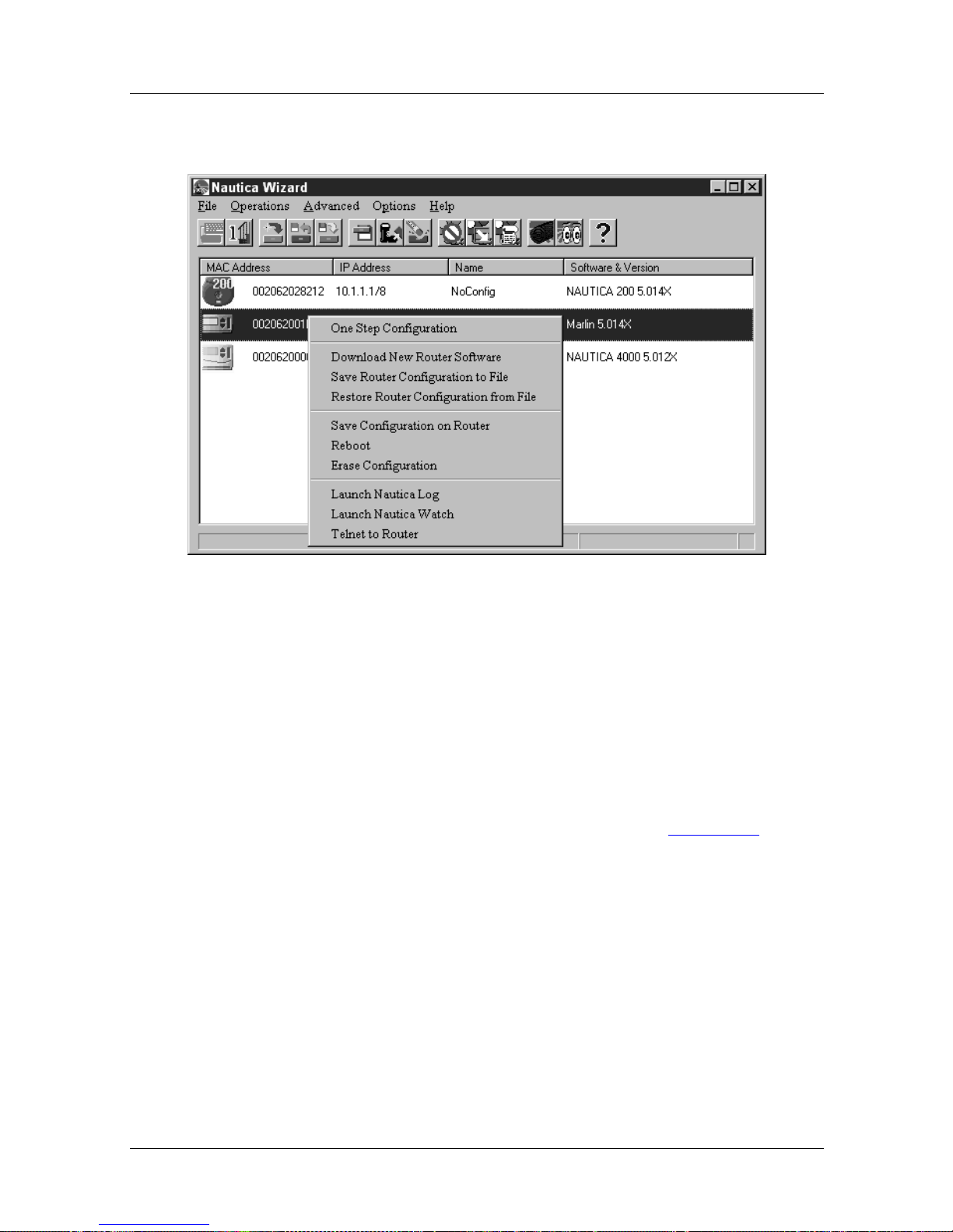
Nautica Configuration W izard Reference Gu ide
• Right clicking on a router’s icon and selecting Launch
Nautica Log from the Quick menu:
Figure 1-39. Nautica Wizard Quick Menu
Nautica Log allows you to view SysLog information. It is simi lar
to running the Trace Window command in BCC.
Nautica Log should only be used to troubleshoot problems with
the router. The information it displays is concerned with actual
activity on the router.
For more information on Nautica Log, refer to Chapter 20
.
1-46 118814-D Rev. 00
Page 85
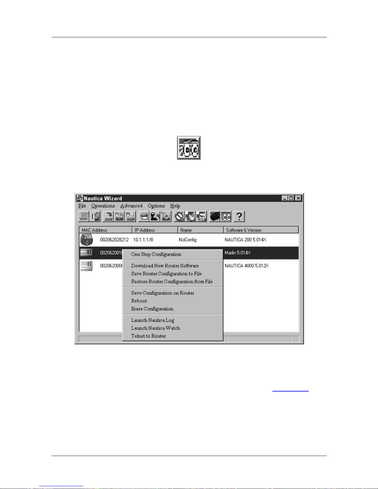
Launch Nautica Watch
Nautica Watch is a virtual LED program that allows you to
monitor your Nautica router.
This command can be accessed with a unit selected and by:
• Clicking on Operations > Launch Nautica Watch
• Clicking on the Nautica Watch button in the too lbar:
• Right clicking on a router’s icon and selecting Nautica Watch
from the Quick menu:
Menus and Basic Procedures
Figure 1-40. Nautica Wizard Quick Menu
For more information on Nautica Watch, refer to Chapter 21
118814-D Rev. 00 1-47
.
Page 86
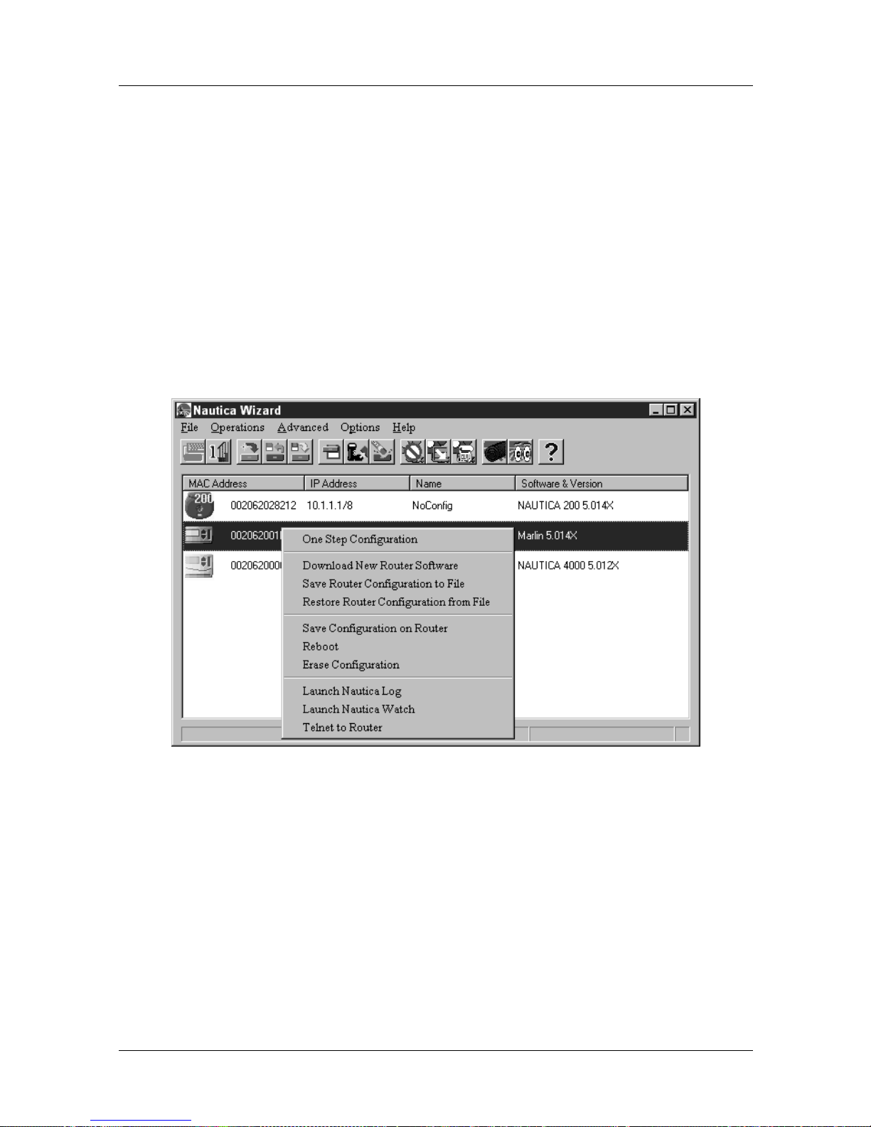
Nautica Configuration W izard Reference Gu ide
Telnet to Router
Nautica Wizard allows you to configure your router to an
advanced level, but there are some options that cannot be set
using the router, particularly Frame Relay settings.
By using Telnet to access the router software directly, it is
possible to configure all the router’s features.
To telnet to a router:
1. Right click on the router you want to telnet to.
2. In the Quick menu, select the Telnet to Router command:
Figure 1-41. Nautica Wizard Quick Menu
3. A telnet session is opened:
1-48 118814-D Rev. 00
Page 87
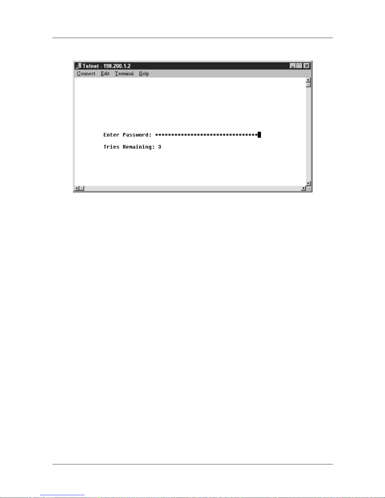
Menus and Basic Procedures
Figure 1-42. Telnet Session
4. Type in the router password and press enter. You are
taken into the Bay Comman d Console (BCC).
For more information on how to use BCC, refer to the online
manual “NauticaRS 5.0 Reference Guide” on the CD that
accompanied your installation.
118814-D Rev. 00 1-49
Page 88
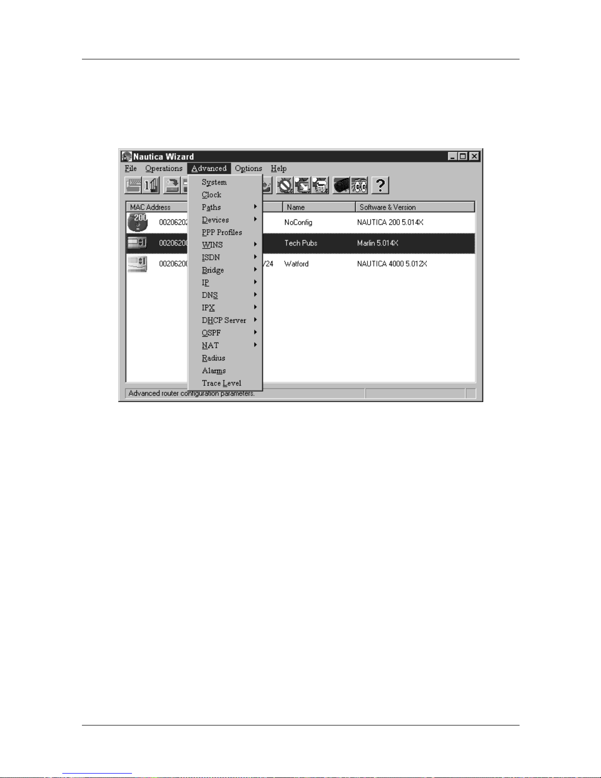
Nautica Configuration W izard Reference Gu ide
Advanced Menu
With a unit selected, the comma nds in the Operations menu are as
follows:
Figure 1-43. The Nautica Wizard Advanced Menu
1-50 118814-D Rev. 00
Page 89
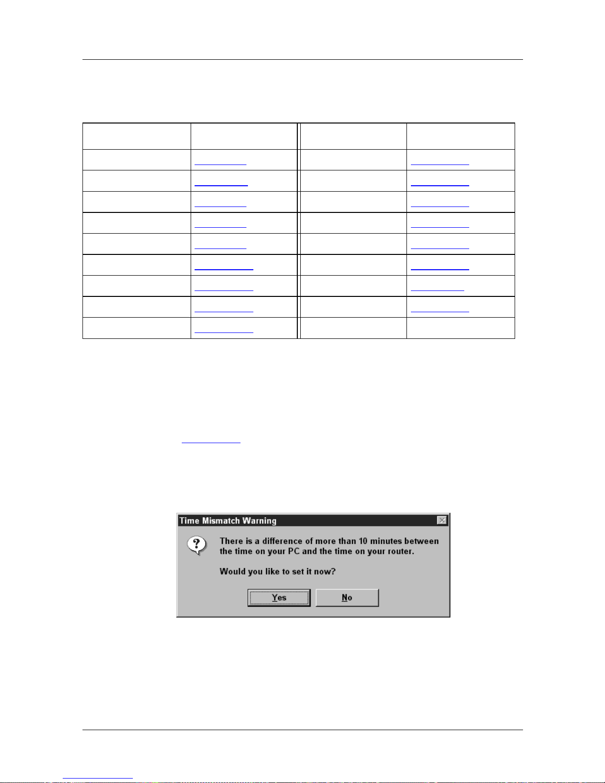
Menus and Basic Procedures
In the table below, click on the chapter number to view the
relevant command instructions.
Command Chapter/Page Command Chapter/Page
System Chapter 2 DNS Chapter 19
Clock page 1-51 IPX Chapter 13
Paths Chapter 3 DHCP Server Chapter 15
Devices Chapter 8 OSPF Chapter 16
PPP Profiles Chapter 9 NAT Chapter 17
WINS Chapter 18 RADIUS Chapter 14
ISDN Chapter 10 Alarms page 1-53
Bridge Chapter 11 Trace Level Chapter 20
IP Chapter 12
Clock
The Nautica 4000 and Nautica Marlin have an internal clock
which allows you to set features like ISDN Timebands
Chapter 10). It is important that this clock and the clock in your
(
PC agree.
If there is a disagreement, the following dialog box appears when
you click on Advanced > System:
Figure 1-44. Time Mismatch Warning
118814-D Rev. 00 1-51
Page 90
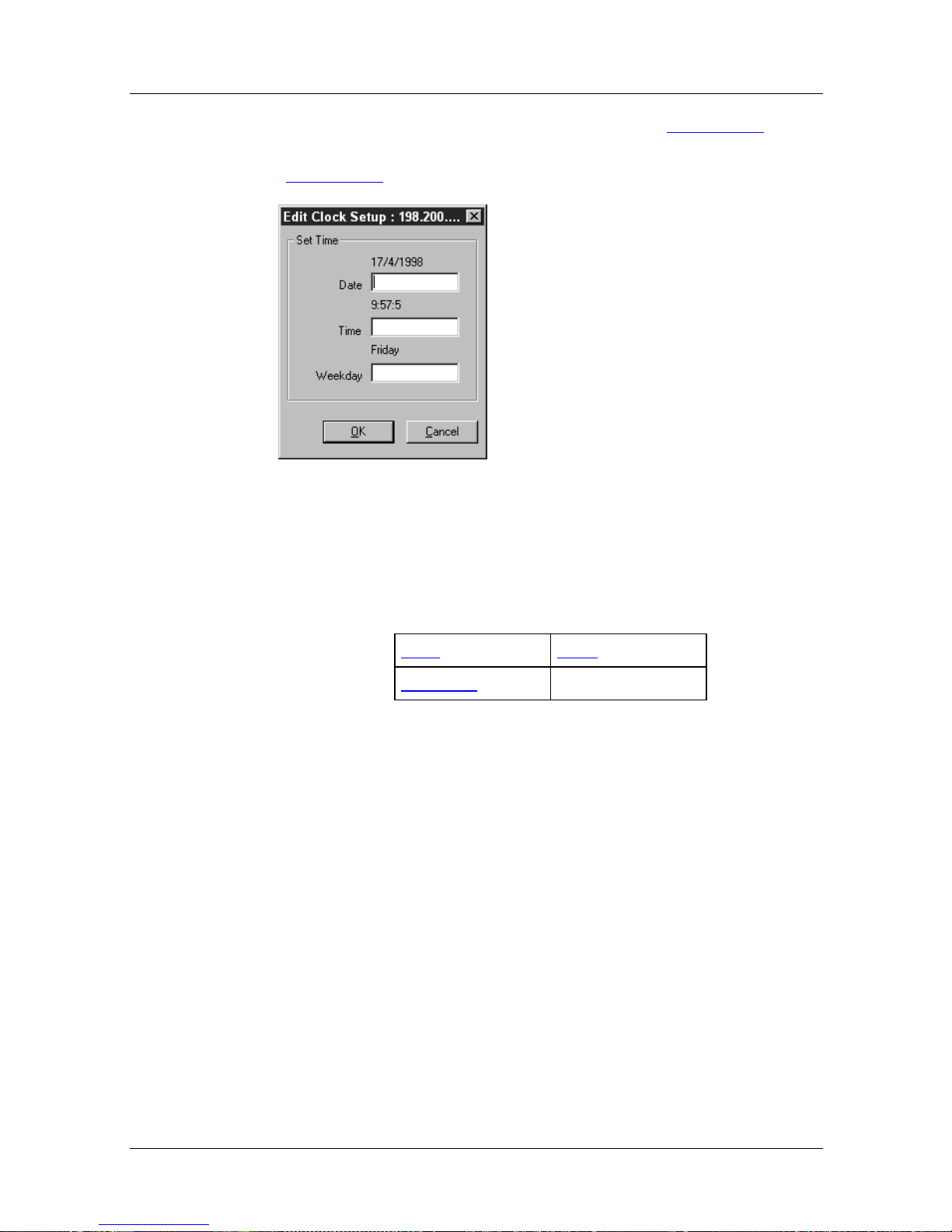
Nautica Configuration W izard Reference Gu ide
To amend the clock, click on the Yes button in Figure 1-44, or
click on Advanced > Clock. The Edit Clock Setup window
(Figure 1-45
) appears:
Figure 1-45. Edit Clock Setup
In the table below, click on the parameter for whic h you require
further assistance.
Date Time
Weekday
Parameter: Date
Default: (Blank)
Options: The current date
Function: Allows you to enter the correct date.
Instructions: Enter the date, the format must be dd/mm/yyyy (day/
month/year). In order to meet year 2000 compliance
issues, the year has to be entered as four digits, for
example, 1998.
1-52 118814-D Rev. 00
Page 91

Menus and Basic Procedures
Parameter: Time
Default: (Blank)
Options: The current time
Function: Allows you to enter the correct time.
Instructions: Enter the time, the format must be hh:mm:ss
(hour:minute:second).
Parameter: Weekday
Default: (Blank)
Options: The current day of the week
Function: Allows you to enter the correct day of the week.
Instructions: Enter the current day of the week. Type the day out in
full, abbreviations are not allowed in this field.
Alarms
Alarms are generated when your router detects an error. The
alarms are stored in the Alarms Table. To display the Alarms
table:
1. Select a router in the Nautica Wizard window (Figure
1-3).
2. Clic k on Advanced > Alarms.
3. The Router Alarms Table (Figure 1-46
) appears :
118814-D Rev. 00 1-53
Page 92
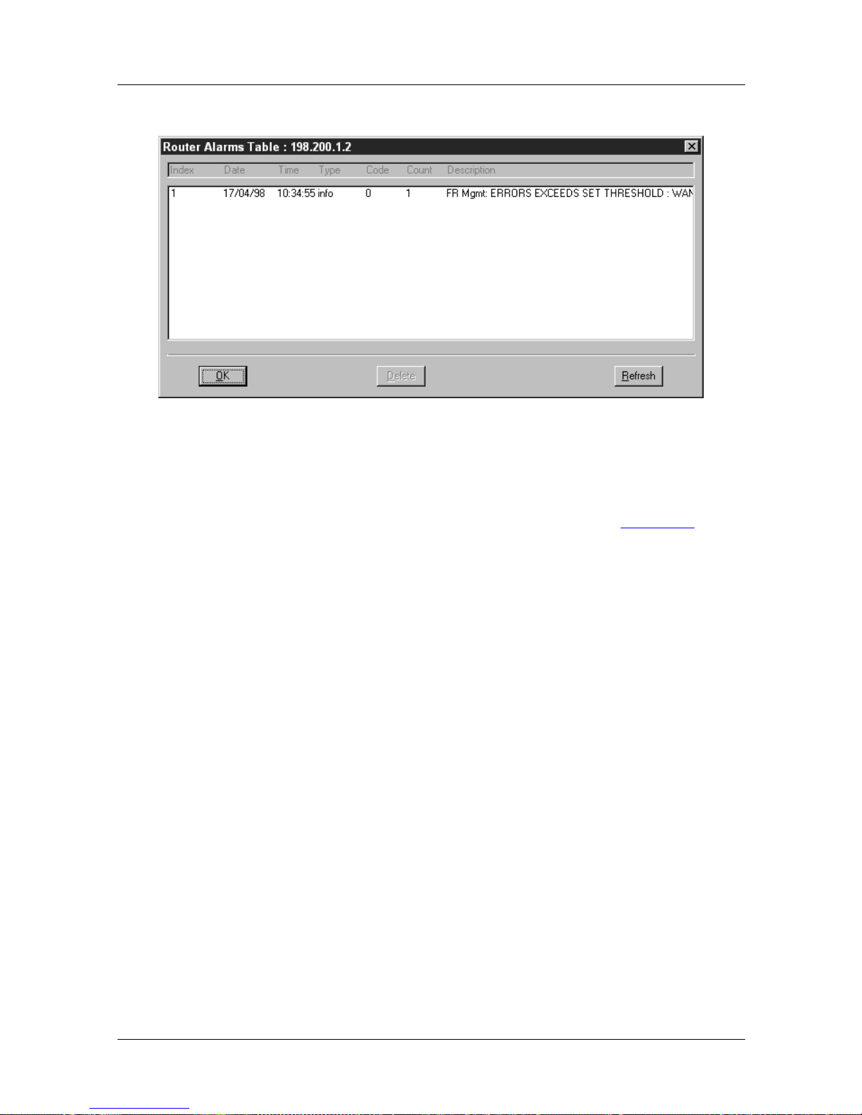
Nautica Configuration W izard Reference Gu ide
Figure 1-46. Router Alarms Table
To delete an alarm, select it in the table and click on the delete
button. To clear all the alarms, reboot the router (page 1-44
).
1-54 118814-D Rev. 00
Page 93
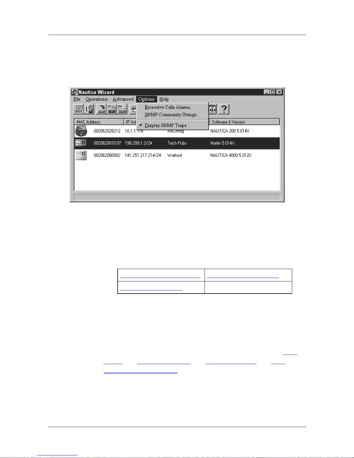
Options Menu
With a unit selected, the commands in the Options menu are as
follows:
Menus and Basic Procedures
Figure 1-47. Nautica Wizard Options Menu
In the table below, click on the command for which you require
further assistance.
SNMP Community Strings Excessive Calls Alarms
Display SNMP Traps
SNMP Community Strings
Simple Network Management Protocol (SNMP) is the protocol
Nautica Wizard uses to communicate with all its routers when
you update their configuration using the commands in the File
Menu, the Operations Menu, the Advanced Menu and The
Nautica Wizard Toolbar.
118814-D Rev. 00 1-55
Page 94
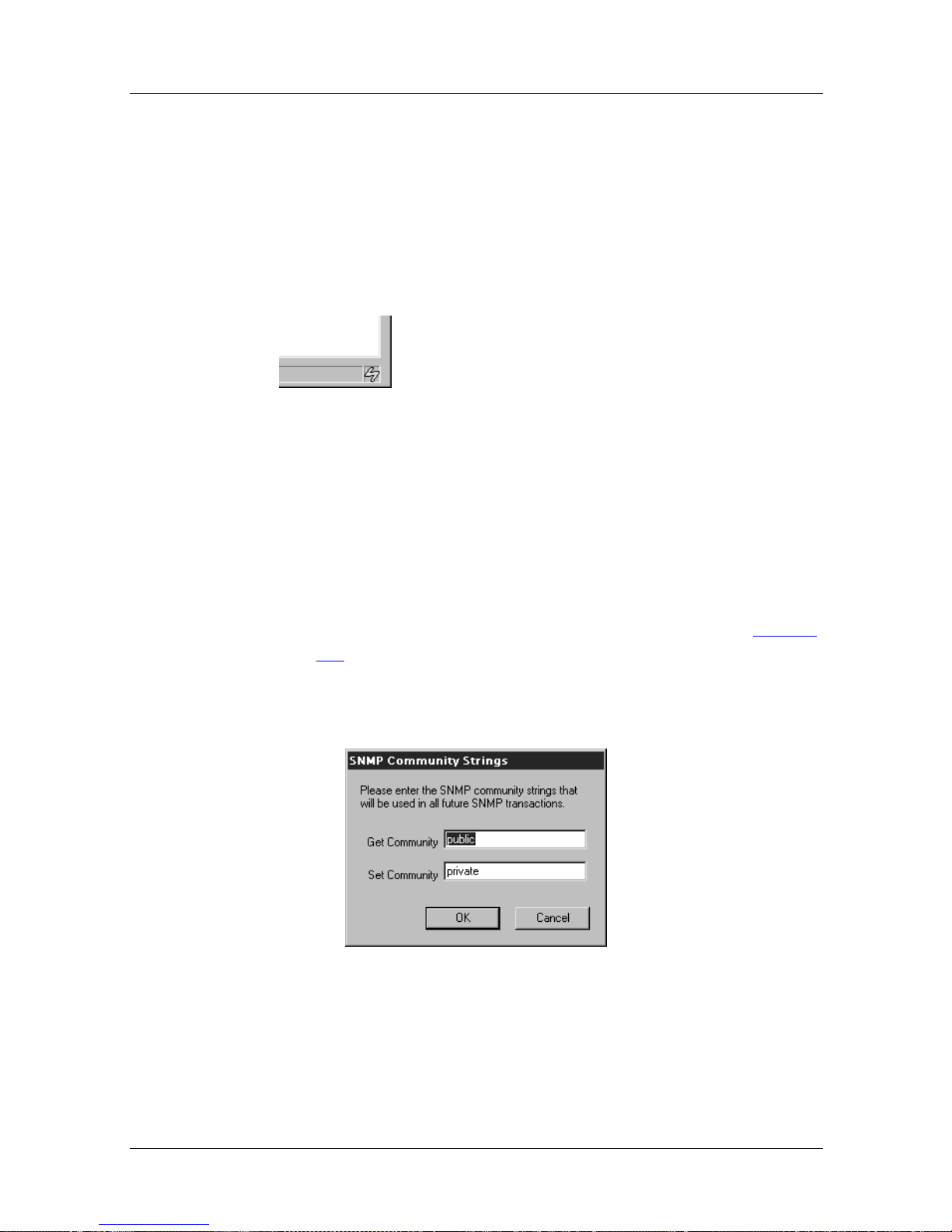
Nautica Configuration W izard Reference Gu ide
Every five seconds, Nautica Wizard sends out a discovery
broadcast to the network using a proprietary protocol. When you
make changes to a router’s configuration, an SNMP pack et is sent
out by Nautica Wizard.
Nautica Wizard shows when it is sending out these packets by
displaying a small yellow lightening bolt in the bottom right
corner of the Nautica Wizard window:
Figure 1-48. Management Indicator
Setting the SNMP community strin gs sp eci fies whether or not
Nautica Wizard can read or write to a specified router. The strings
have to agree for any configuration updates to take effect.
To change or view the SNMP Community s trings:
1. Click on a router in the Nautica Wizard window (Figure
1-2).
2. Click on Options > SNMP Community Strings.
3. The SNMP Community Strings window appears:
Figure 1-49. SNMP Community Strings Window
1-56 118814-D Rev. 00
Page 95
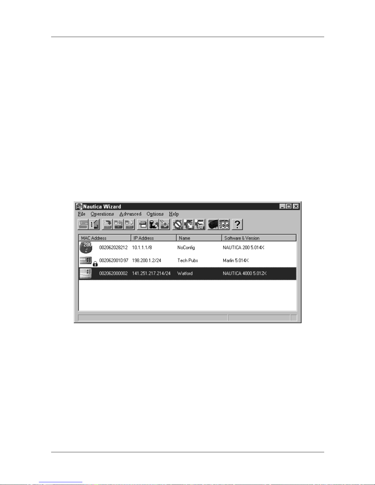
Menus and Basic Procedures
4. Changing the Get Community string sets the read access
to this router. The string must match in both the sending
and receiving routers f or the configuration inf ormation to
be read.
5. Changing the Set Community string changes the write
access to this router. The string must match in both the
sending and receiving routers for the configuration
changes to be made.
6. Once you have viewed or amended the SNMP
Community Strings, click on the OK button to return to
Nautica Wizard.
If you do change the community strings for a router, the router
icon in the Nautica Wizard window changes to show a small lock
to reflect this:
Figure 1-50. SNMP Community Router Lock
118814-D Rev. 00 1-57
Page 96
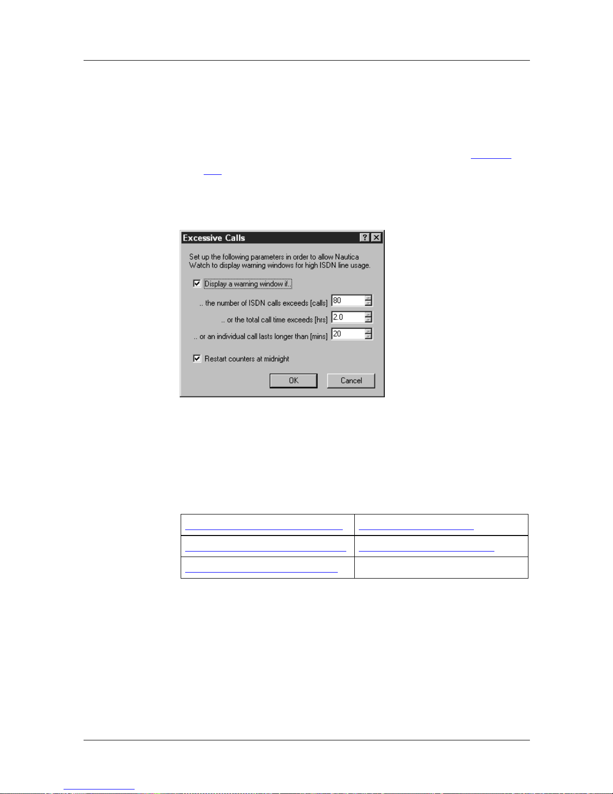
Nautica Configuration W izard Reference Gu ide
Excessive Calls Alarms
The Excessive Alarms allows you to set up alarms on certain
events. To display the Excessive Alarms window:
1. Select a router in the Nautica Wizard window (Figure
1-3).
2. Clic k on Options > Excessive Alarms.
3. The Excessive Calls window appears:
Figure 1-51. Excessive Calls Window
In the table below, click on the parameter for whic h you require
further assistance.
Display Warnings Window If... Excessive ISDN Calls
Excessive Individual Call Time Excessive Total Call Time
Restart Counters at Midnight
1-58 118814-D Rev. 00
Page 97

Menus and Basic Procedures
Parameter: Display Warnings Window If...
Default: Disabled
Options: Disabled, Enabled
Function: En a bling this parameter allows the setting of specific
alarms.
Instructions: If you want to set up alarms, enable this opt ion .
Parameter: Excessive ISDN Calls
Default: 80
Options: A valid number of calls
Function: Displays a warning window if the number of ISDN calls
exceeds the number shown here.
Instructions: Enter your maximum ISDN call limit.
Parameter: Excessive Total Call Time
Default: 2.0
Options: A valid time in hours
Function: If the total time of all the current ISDN calls exceeds the
time here, a warning window is displayed.
Instructions: Enter a time restriction if required.
118814-D Rev. 00 1-59
Page 98

Nautica Configuration W izard Reference Gu ide
Parameter: Excessive Individual Call Time
Default: 20
Options: Enter a time in minutes
Function: Allows you to display a warning window if an individual
call exceeds this limit.
Instructions: Enter a time limit in minutes if required.
Parameter: Restart Counters at Midnight
Default: Enabled
Options: Enabled, Disabled
Function: Restarts all the call alarm counters at midnight.
Instructions: Disable this parameter if you do not want the counters to
restart.
Display SNMP Traps
When SNMP detects an error, a trap is generated. These traps can
be displ ayed on your PC or any other host .
To display SNMP traps on your PC:
1. Select a router in the Nautica Wizard window (Figure
1-3).
2. Clic k on Advanced > System.
1-60 118814-D Rev. 00
Page 99
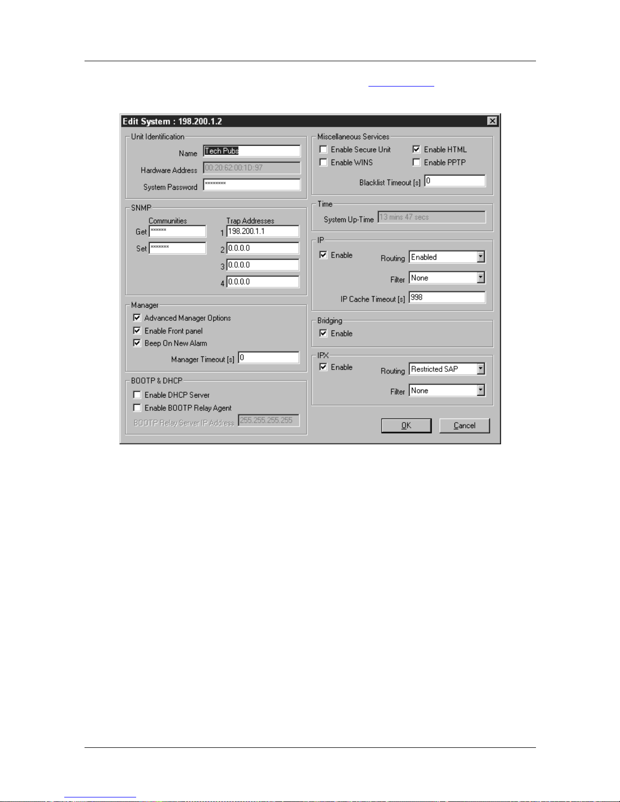
Menus and Basic Procedures
3. In the Edit System window (Figure 1-52), enter the IP
address of your PC as one of the SNMP Trap Addresses.
Figure 1-52. Edit System Window
4. Ensure there is a tick against the Display SNMP Traps
command in the Options menu (If there isn’t, reselect the
command).
118814-D Rev. 00 1-61
Page 100
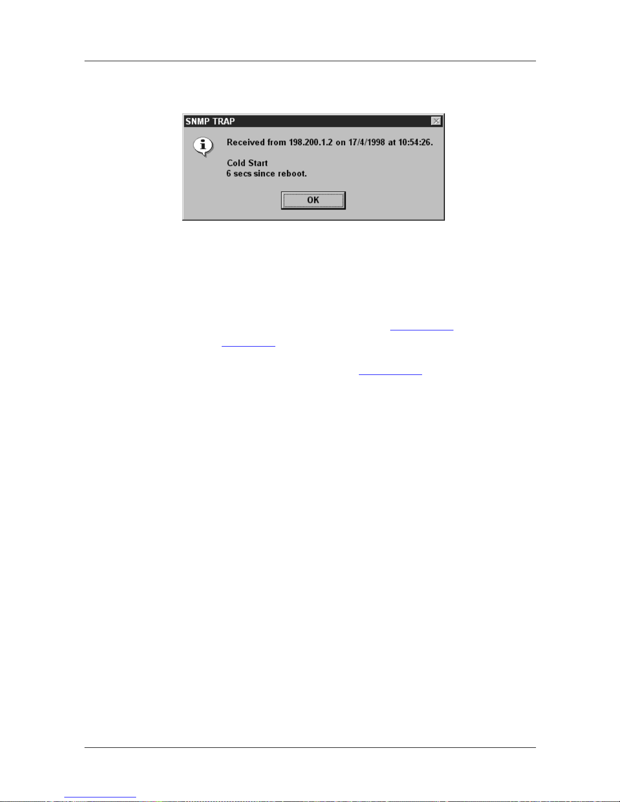
Nautica Configuration W izard Reference Gu ide
5. Now when SNMP T raps are generated, they ar e displayed
in dialog boxes on your PC:
Figure 1-53. SNMP Trap Window
If you want to display an SNMP Trap now to check that the
system is working. With your PC set and one of the SNMP Trap
addresses in the Edit System window (Figure 1-52
router (page 1-44
).
), reboot the
An SNMP Trap dialog box as in Figure 1-53
appears.
1-62 118814-D Rev. 00
 Loading...