

Page 1

R
ADIUS
R
EFERENCE MANUAL
Issue 1.0
Issue 1.0 MAN-RADIUS-REF
Page 2

All rights reserved. This document may not in whole or part be copied,
photocopied, reproduced, translated or reduced to any electronic medium or
machine readable form without the prior written permission from Bay
Networks.
The information contained in this manual is believed to be accurate,
however, no responsibility is assumed by Bay Networks for its use, nor for
any infringements of patents or other rights of third parties resulting from
its use.
All trademarks are acknowledged.
1996 Scorpion Logic Ltd. A Bay Networks company
MAN-RADIUS-REF Issue 1.0
Page 3

BOUT THIS MANUAL
A
Chapter 1 - Introduction
This chapter gives an overview of the features of the RADIUS Server and
provides an introduction to its features and facilities.
Chapter 2 - Tutorial
This chapter gives a step by step guide to the configuration of a sample
Network. It covers the configuration of the RADIUS Server, the Network
Access Server (in this case a Nautica Marlin Router), a small office
Network and a mobile dial-in user.
Chapter 3 - Reference
All RADIUS specific management structure and forms, configuration
parameters and status information are described in detail in this chapter.
Issue 1.0 MAN-RADIUS-REF
Page 4

MAN-RADIUS-REF Issue 1.0
Page 5

C
ONTENTS
Section ……………………………………………… Page
Chapter 1 - Introduction
Welcome to Nautica RADIUS 1-1
About This Manual 1-1
Nautica Radius Features 1-2
RADIUS Background 1-2
Theory Of Operation 1-3
Document Conventions 1-4
What You Need 1-6
Hardware 1-6
Software 1-6
Knowledge 1-7
RADIUS Installation 1-8
Chapter 2 - Reference
Introduction 2-1
The Marlin Router and RADIUS 2-1
RADIUS Manager Menu Map 2-2
NAS Types 2-3
Configure NAS Types 2-3
NAS Device Types 2-4
NAS Units 2-5
Configure NAS Units 2-5
NAS Name 2-6
Quality Of Service 2-9
Grade of Service 2-10
Priority Timebands 2-11
Accounts 2-13
Account Information 2-14
Path Type 2-17
Multi-Link Operation (PPP or Nautica Paths) 2-18
Multi-Link Nautica/PPP 2-19
Undistinguished (OEM NAS Connections to RADIUS) 2-20
IP Networking 2-21
RIP Operation 2-22
RIP Type 2-22
Static Route Tables 2-23
IPX Networking 2-24
Outgoing Call Support 2-26
Service 2-27
v
Page 6

C
ONTENTS
Section …………………………………………….. Page
Chapter 2 - Reference (cont.)
Session Parameters 2-27
Accounting 2-28
RADIUS Server 2-29
Nautica Radius Server Menu Map 2-29
File 2-30
RADIUS Server Settings 2-30
Event Log 2-34
Status 2-35
Device Status 2-35
QOS Status 2-36
Account Status 2-37
Account Allocation 2-38
Account Rollover 2-38
Event Log Window 2-39
Breakdown of Account Records 2-39
Example Event Log of an Incoming Connection 2-41
Example Event Log of an Outgoing Connection 2-44
Chapter 3 - Tutorial
Nautica RADIUS Tutorial 3-1
Overview of Sample Test Network 3-2
RADIUS Configuration Tutorial 3-4
RADIUS Installation 3-5
Configuration Procedure 3-6
RADIUS Manager Configuration 3-7
1. Configuring a NAS Type 3-7
2. Configuring a NAS Unit 3-8
3. Configuring the Quality Of Service (QOS) Option 3-10
4. Configuring the Accounts Option 3-14
Configuring the Marlin Router on the HQ Backbone LAN 3-34
Configuring the CLAM Router at the Remote Office 3-47
Configuring the Roving User’s P.C. 3-55
vi
Page 7

C
ONTENTS
v
Page 8

C
ONTENTS
vi
Page 9

Introduction
I
NTRODUCTION
Welcome to Nautica RADIUS
Thank you for purchasing Nautica RADIUS as part of your remote access
strategy.
We believe you will be delighted with this product as it is easy to use, and
provides unrivalled Security, Accounting and Quality of Service facilities for
both Intranet and Internet users alike.
BOUT THIS MANUAL
A
This reference Manual describes how Nautica RADIUS is installed and
configured with the Nautica family of routers. It should be used in
conjunction with the relevant manuals for each Nautica unit you will be using.
If you wish to use Nautica RADIUS in conjunction with other manufacturers’
products, then the relevant manuals for their products must also be available.
1-1
Page 10

I
NTRODUCTION
AUTICA
N
RADIUS F
EATURES
Nautica RADIUS is an Authentication, Authorisation and Accounting system
based on the R.A.D.I.U.S. (Remote Authentication Dial In User Service)
standard which can be adapted to a broad range of different network
requirements of Enterprise, Internet Service Providers (ISPs), Telcos, Value
Added Networks (VANs), Intranets and other service operations. Such
networks may operate in a variety of environments such as:
Public companies providing access to networks for general or specific
usage, such as ISPs, financial information services and scientific
information services for example.
Private Networks for large organisations, where access is provided for
internal operational divisions and perhaps external trading companies
with security and on a chargeable basis. These include: Financial
Services, University Campus, Software Services and large companies
providing remote office, home and Intranet connections for many
departments.
All of these network systems have a common theme :- Remote Access, for the
individual user or the Remote Branch Office, whether via PSTN or ISDN.
RADIUS B
ACKGROUND
RADIUS consists of two functions, RADIUS Authentication and RADIUS
Accounting. It uses a client/server based security system designed in
accordance with a model of distributed security recommended by the Network
Access Server Working Group of the IETF. RADIUS has been submitted as
an RFC to become an Internet standard, and has been adopted as the protocol
and system of choice by most of the security product manufacturers. RADIUS
is rapidly gaining popularity as an open protocol and architecture with all the
key manufacturers of communications products, as it is both an easy and
efficient means of controlling and accounting for access to backbone
networks.
1-2
Page 11

Introduction
HEORY OF OPERATION
T
RADIUS Authentication in a network acts as a distributed security system
which uses an authentication server to address the issues of Secure Access to
central services through dial-in devices called Network Access Servers
(NAS). By their nature, Dial-In devices are a point of vulnerability for a
network, since anyone can acquire the telephone or ISDN number of the
service, and with the appropriate calling device (such as a modem, ISDN TA
or personal Router), can attempt to gain access to the service.
RADIUS provides a secure mechanism by which NAS devices can
authenticate incoming calls at a central unit before allowing the Account
access to any part of the network. When an Account is granted access, the
RADIUS Server can configure the NAS to customise the services.
Distributed Security allows the separation of the communications process
from the user authentication. This allows a central point of authentication,
configuration, and a single database which many NAS devices can access
without the need to hold the authentication information for all dial-in
Accounts at the NAS (these Accounts can potentially run into several
thousand). The use of this central repository makes RADIUS more secure and
more scaleable than systems based upon many distributed points.
RADIUS authenticates users through a series of communications which take
place from Account (User) to NAS where the RADIUS Client resides, then
from RADIUS Client to RADIUS Server wher the Account Authentication is
processed. The results are then passed onto the RADIUS Client. This
separation of communication activity is another level of security preventing
access at any point to the network in order to maintain its integrity.
As with all standards, RADIUS includes the facility to add extended attributes
so that specific features of different manufacturers’ products may be
supported.
Additionally, RADIUS supports an Accounting mechanism, which records all
connection/disconnection events and bandwidth utilisation by each Account.
Accounting information is reliably delivered by the RADIUS protocol.
1-3
Page 12

I
NTRODUCTION
Authentication and Accounting information is keyed using MD5 encryption
algorithms and cannot be modified in transit, since both NAS device and the
RADIUS server validate received packets.
OCUMENTATION CONVENTIONS
D
Mouse-it
•
Nautica RADIUS only makes use of the left mouse button.
[click]-means press and release once.
[double-click] - means press and release twice in quick succession.
[drag] - means press the button and hold, while moving the object contacted.
Menu Commands
•
Menu Commands are in the form of Menu Name/Menu command.
e.g. Select Edit/Undo
Button Names
•
Button Names are in the form Button Name.
e.g. Select the OK button
Key Names
•
Key Names are in small capitals:
ESCAPE
.
Key Combinations and Sequences
•
A plus sign (+) between keys means press both keys at the same time.
1-4
Page 13

Introduction
e.g. Press
A comma between keys means the keys should be pressed in succession.
e.g. Press
What You Type
Anything you should type is in italics.
e.g. Type 123.456.111
Where the typed input is variable then it will be in brackets.
e.g. Type {Your IP Address}
Handy Hints
ALT+ESCAPE
ALT, SPACE
These are designed to assist you during the process either as reminders or
useful tips and will be in bold italic.
e.g. Note: Always Save your configuration after a change.
Warnings
1
The insertion of a
could result in a loss of data or connections.
is a caution meaning failure to follow the procedure
1-5
Page 14

I
NTRODUCTION
HAT YOU NEED
W
ARDWARE
H
Nautica RADIUS can be installed on any Windows ’95 platform. We strongly
recommend that it is dedicated to the task of RADIUS to maintain security and
performance across the network.
The recommended dedicated hardware platform for up to 5,000 users is as
follows:
Minimum 486 DX2 66MHz, IBM compatible PC, with 12 Mb RAM.
Ethernet Card.
SVGA (800 x 600) Monitor.
Keyboard.
Mouse.
OFTWARE
S
Microsoft Windows 95.
TCP/IP network software.
A Windows 95 installation program is included with Nautica RADIUS.
Note: The addition of Nautica MicroManager (an SNMP based Network
Manager) to this platform could provide an additional window to the
network should you need it.
1-6
Page 15

Introduction
NOWLEDGE
K
It is recommended that you have at least a basic knowledge of the following
technologies and User Account Information before commencement of
installation procedure
Windows 95.
TCP/IP Address structures.
TCP/IP Addresses for your Network.
If using Novell Netware, Novell IPX and Novell SPX Address structures
and how they apply to your network.
The ISDN Numbers for each of your local and remote installations.
A profile of the people and sites who are using/intending to use the network.
A profile of the data-flow to those sites.
A list of any predefined CHAP Secrets, Nautica Passwords or User Password
to be used during Authentication.
You are now ready to commence installing and configuring your Nautica
RADIUS system. We have also included a T
UTORIAL
chapter, which
configures the Nautica RADIUS Server in a standard remote access
environment. We strongly recommend that you start off by configuring your
RADIUS Server using this Tutorial first, then progress onto your own specific
configuration.
1-7
Page 16

I
NTRODUCTION
RADIUS I
NSTALLATION
The RADIUS Server and the RADIUS Manager suite of programs is provided
on two 3.5" Floppy Disks. These are labelled “Disk 1” and “Disk 2”.
1. Place the 3.5" Floppy Disk labelled Disk 1 into the A Drive of the
Windows 95 PC.
2. Select the Start option on the Windows 95 Task Bar by placing the mouse
pointer over the “Start” Button and clicking the left mouse button.
3. [Click] the Run option.
4. Type A:\Setup.exe in the “Open” box.
5. [Click] the OK Button.
6. Follow the instructions given in the Setup Windows and amend any
settings as necessary.
7. When the Setup program is complete the “Nautica RADIUS” Window is
displayed. [Double-click] the red RADIUS_M icon in the “Nautica
RADIUS” Window. This runs the RADIUS_M program.
8. When the “RADIUS Manager” window appears [click] the Minimise
Button. This will place the RADIUS Manager Button on the Task Bar.
9. [Double click] the green RADIUS_S icon in the “Nautica RADIUS”
Window. This runs the RADIUS_S program
10. When the “RADIUS Server” window appears [click] the Minimise
Button. This will place the RADIUS Server Button on the Task Bar.
11. [Click] the Close Button on the “Nautica RADIUS” Window.
1-8
Page 17

Introduction
AUTICA
N
RADIUS F
ILES
The Files you should now have installed on your hard drive are as follows:-
Two executable files :-
1) RADIUS_S.EXE
This is the Server program which communicates with the NAS RADIUS
Client software. It validates the users with the details stored in the
RADIUS.LST file, which is created when RADIUS_M is run.
2) RADIUS_M.EXE
This is the RADIUS Manager program. This provides the configuration for
the NASs and Users. It also generates the User database as new users are
configured. The RADIUS Manager is generally only used when adding new
User or NAS configurations or when making changes to existing Users and
NASs. As such it automatically reloads information changes to the
RADIUS.LST file when changes are made.
Other Files installed are:
CW3215.DLL BIDS45.DLL
BC450RTL.DLL BIDS45F.DLL
BWCC.DLL BWCC32.DLL
OWL250F.DLL OWL250.DLL
If the RADIUS.LST file does not already exist one is automatically created
when the RADIUS_M.EXE program is run.
1-9
Page 18

I
NTRODUCTION
1-10
Page 19

R
EFERENCE
I
NTRODUCTION
The Bay Networks RADIUS implementation is such that the RADIUS Server
functionality and the Account and NAS configuration are carried out using
separate executable programs, RADIUS_M.EXE and RADIUS_S.EXE. This
allows configuration changes to be made without having to halt the RADIUS
Server, providing continuous online network operation.
The initial and day to day configuration is carried out by the RADIUS_M
program (RADIUS Manager), while the actual RADIUS Server function of
Authentication, Access Control and Accounting is performed by the
RADIUS_S program.
The Reference Section is arranged in such a way that it guides the reader
through the RADIUS Manager Menus and gives a brief description of each
selectable parameter and their available options. The Reference section then
follows describes the Menus and options provided by the RADIUS Server
program.
It should be noted that an “Account” is almost equivalent to a “Path” on a
Nautica Router, and as a result all common variables use the same name. It is
recommended that a Marlin or CLAM Version 3 Router Reference Manual is
read in conjunction with this RADIUS Reference Manual to obtain an all
round understanding of the common variables used.
T
HE MARLIN ROUTER A ND
The Nautica family, particularly the Marlin need to be configured for
RADIUS operation prior to installation. To carry out this configuration,
RADIUS
please see the relevant section of the Nautica Manual.
For other manufacturer’s products please refer to the relevant manual and
configure them accordingly.
Note: Marlins configured for use with a RADIUS Server start with no Paths
configured. All Paths are downloaded using the RADIUS protocol.
2-1
Page 20
R
EFERENCE
This generally also applies to other manufacturer’s products, where the
RADIUS protocol will download the paths using the profiles input into
RADIUS for that specific product.
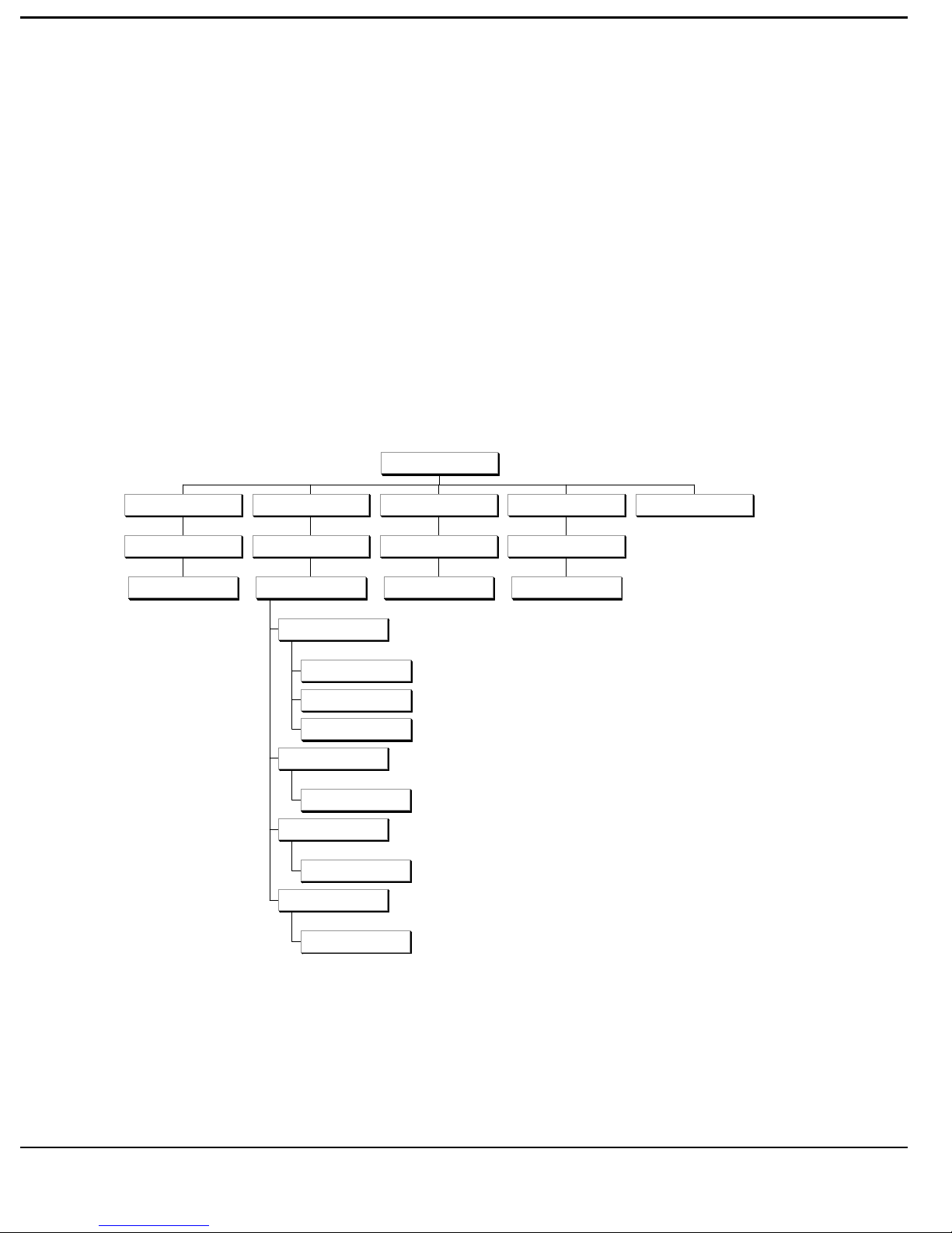
RADIUS M
ANAGER MENU MAP
Nautica RADIUS Manager Menu Map
RADIUS MANAG ER
Quality o f S e rv ic e
Grade O f Service
Priority Timebands
Account
Re m o te A cc ou nts
A cc ou n t In form a tion
P a th T yp e
Multi-Link Nautica
M ulti-link PP P
Undistinguished
IP N e twork ing
NAS Types
Configure NAS Types
NAS DeviceTypes
NAS Units Key G enerator
Configure NAS Units
NAS Name
IPX N etwro king
Service
Session Parameters
2-2
IP P a th
IPX Path
Page 21
R
EFERENCE
NAS T
YPES
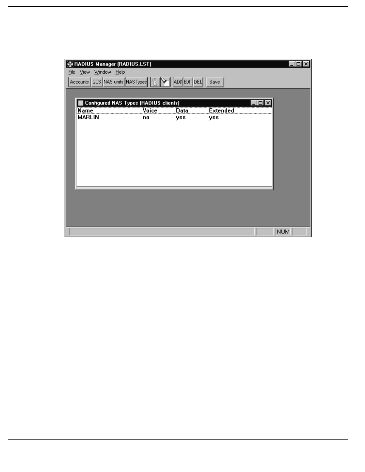
[Click] the NAS TYPES button and the Configured NAS TYPES Menu will
appear.
This Menu describes the NAS Types available for configuration.
ONFIGURE
C
NAS T
YPES
NAME This is the Name of the product type e.g.
Marlin 3000.
VOICE Are Analogue ports supported on the device.
DATA This selects the Data Port of the device.
EXTENDED Does the device support Nautica Extensions to
RADIUS.
2-3
Page 22
R
EFERENCE
To Delete an item from the table, highlight it and [click] the DEL button.
To Edit an item in the table, highlight it and [click] the EDIT button to access
the NAS DEVICE TYPE menu.
To Add an item in the table, highlight it and [click] the ADD button to access
the NAS DEVICE TYPE menu.
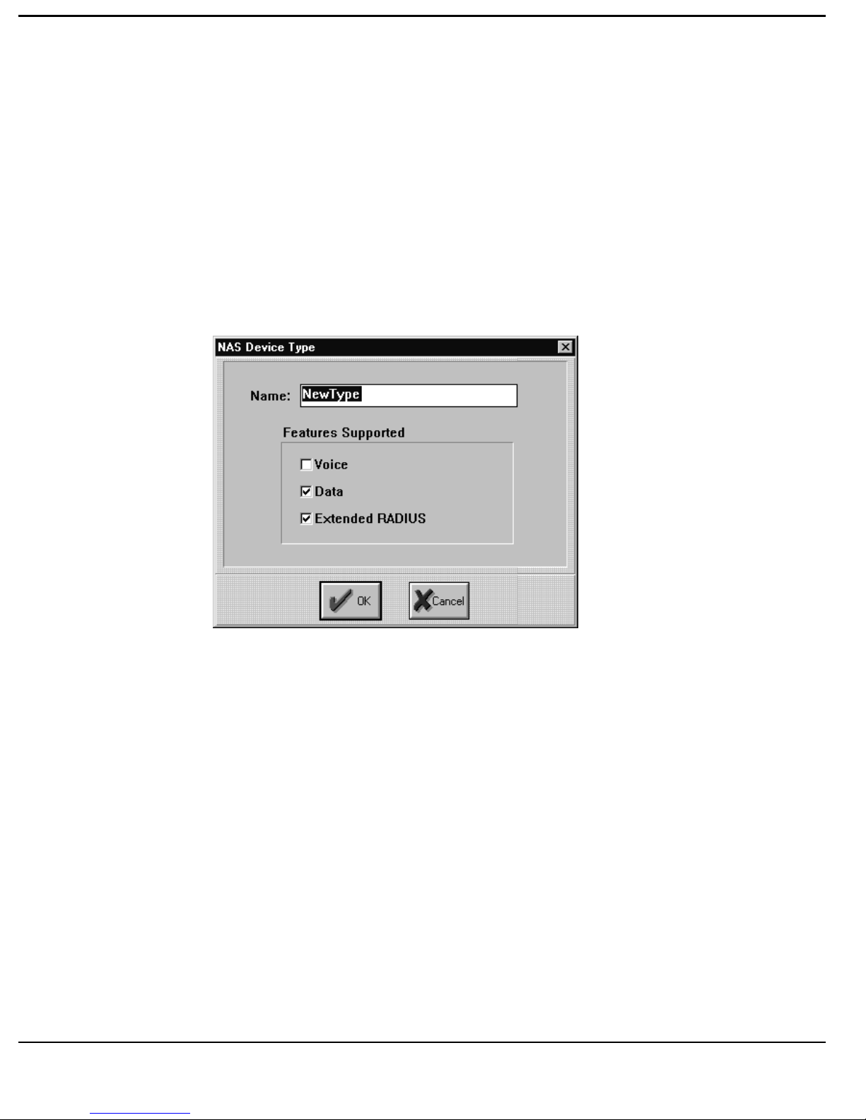
NAS D
EVICE TYPES
Complete the Form for each NAS device to be Added or Edited.
Type {Name of Unit}
Select any other required options.
2-4
Page 23
R
EFERENCE
NAS U
NITS
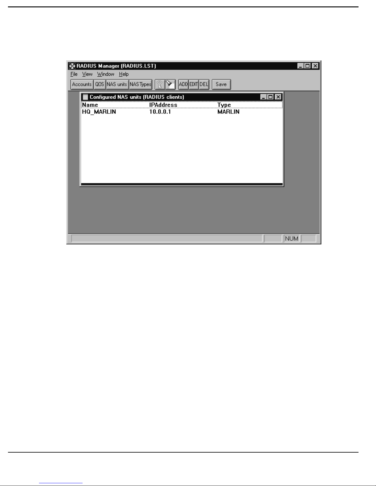
This window describes the Configured NAS Units available.
[Click] the NAS UNITS button to access the CONFIGURE NAS UNITS
menu.
ONFIGURE
C
NAS U
NITS
NAME This is the Name you wish to call the
particular unit. It will usually be the same as
you input into the unit, but can vary if you
require it to do so.
IP ADDRESS This is the IP Address assigned to that
particular NAS Unit.
2-5
Page 24
R
EFERENCE
TYPE This is the NAS Type and should be selected
from the NAS TYPE Menu.
Note: If the NAS DEVICE TYPE you require is not in the list, please revert
back to the NAS DEVICE TYPE menu and enter the NAS Type you
require before proceeding.
NO OF PORTS This is the number of ISDN channels available
on the unit.
To Delete NAS Units from the configuration, highlight the unit and [click] the
DEL button.
To Edit NAS Units on the list, highlight the unit and [click] the EDIT button
to access the NAS NAME menu.
To Add NAS Units to the list, [click] the ADD button to access the NAS
NAME menu.
NAS N
AME
2-6
Page 25

R
EFERENCE
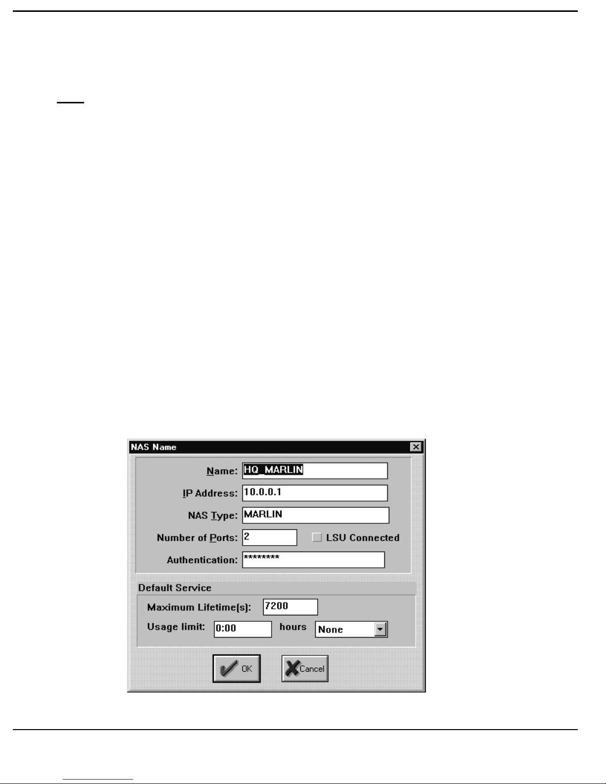
Complete the NAS Name window as follows:NAME Input the Name of the NAS you require. This
will usually be the Name used to configure the
unit from the local manager.
IP ADDRESS Input the IP Address of the NAS unit.
NAS TYPE Select the NAS Type from the NAS DEVICE
TYPE menu, and Type {Device Type Name}.
NUMBER OF PORTS Enter the Number of ISDN channels available
on the NAS.
AUTHENTICATION Enter the SECRET shared between the Server
and the NAS. This SECRET can take the form
of any string of alpha-numeric characters,
upper or lower case, with a maximum size of
31 characters.
Note: This Secret needs to be configured directly onto the NAS. For
Nautica it can be found on the Config. RADIUS menu.
Note: We would recommend that the SECRET string used differs from the
11
NAS Names used and should not easily related. This information
should be stored in a secure place.
LSU CONNECTED To be completed [click] the box where a
Nautica 8000LSU is being used to Cluster
multiple Primary Rate devices.
DEFAULT SERVICE This defines the default available Quality of
MAXIMUM LIFETIME This timer is in Seconds and represents how
Service for that particular NAS. Two
parameters must be set:- Maximum Life-
Timer and Usage Limit.
long a Session can remain connected. The
total time includes periods of inactivity when
2-7
Page 26

R
EFERENCE
the ISDN connection is down. Type (Time In
Seconds).
Note: A Session (i.e. the Path associated with the Account on the NAS
Router) will exist for the time defined by the Maximum Session
Lifetime, whether there is activity or not on the line. The default
Maximum Session Lifetime is 10 mins. If an Account attempts to
reconnect the line after the Session Lifetime has expired the full
RADIUS Authentication process is performed again.
USAGE LIMIT This timer in Hours and Minutes specifies
the amount of time an Account can access the
network on a per Day, Week or Month basis.
Type{Hours:Mins}.
Note: Each time a Session is started the Usage Limit is decremented by the
value of the Maximum Session Lifetime. When the Usage Limit has
been the Account will not be granted access.
Select the required Period from the Drop-Down Menu.
2-8
Page 27
R
EFERENCE
Q
UALITY OF SERVICE
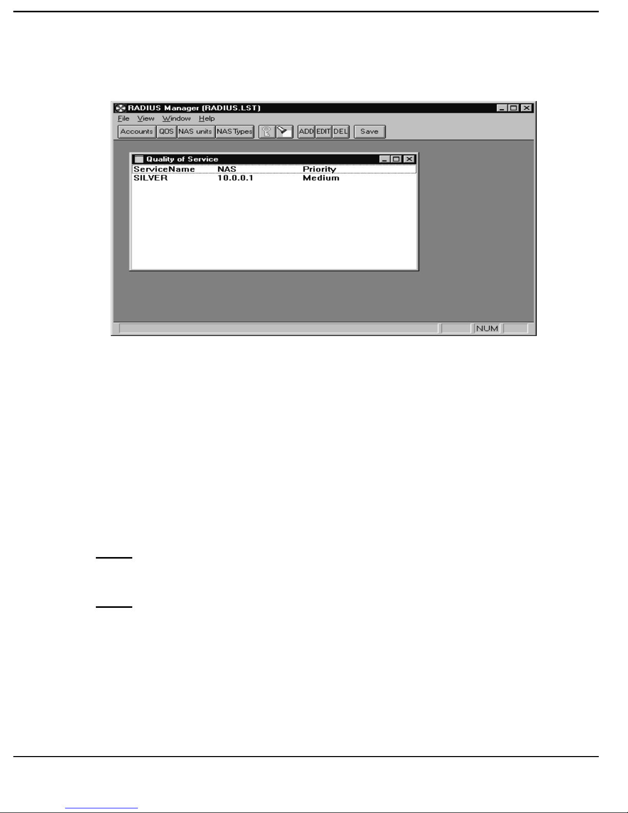
[Click] the Quality Of Service button and access the Quality Of Service
menu.
Service Name The name of the Specific Service (e.g. Gold,
Silver, Bronze etc.)
NAS This is the IP Address of the NAS to which
the Quality Of Service applies.
PRIORITY This will indicate either High, Medium, Low.
Note: If the NAS IP Address is set at 0.0.0.0, then it is part of a NAS Cluster
connected through a Nautica 8000LSU.
Note: Resources are allocated in accordance with this level of priority, i.e.
where Contention occurs Higher priority will be given first option on
any resources.
To Add an item to the Quality of Service [click] the ADD button and access
the GRADE OF SERVICE menu.
2-9
Page 28
R
EFERENCE
To Edit an item, highlight the item, [click] the EDIT button and access the
GRADE OF SERVICE menu.
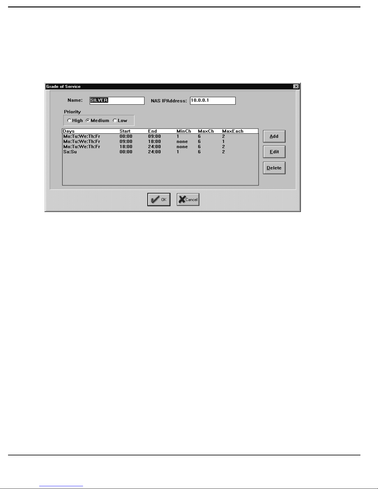
RADE OF SERVICE
G
NAME Complete the Name of the Service required.
NAS IP ADDRESS Enter the IP Address of the NAS. Enter
0.0.0.0 if the NAS is part of a Nautica
8000LSU Cluster.
PRIORITY [Click] High, Medium or Low.
[Click] the EDIT button, or the ADD button to access the TIMEBANDS
menu.
2-10
Page 29
R
EFERENCE
RIORITY TIMEBANDS
P
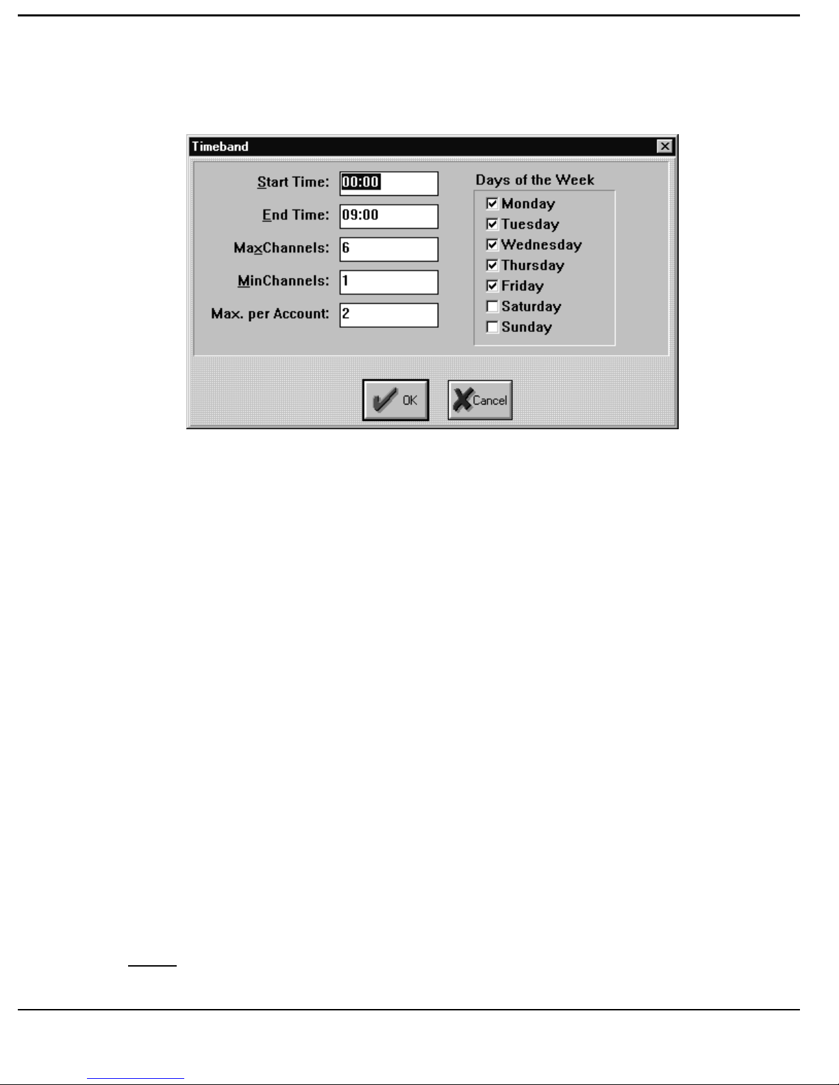
Complete the form with your requirements:
DAYS These are the days when this Grade of Service
may be used. To Select, [click] on the
selection.
START TIME This defines the start time of access to the
Grade Of Service.
END TIME This defines the ending time for access to this
Grade of Service.
MAX CHANNELS The Maximum number of ISDN channels
available for this Grade of Service during that
time period.
MIN CHANNELS The Minimum number of ISDN channels
reserved for this Grade of Service during that
Note: A “0” indicates no channels are reserved.
time period.
2-11
Page 30

R
EFERENCE
MAX PER ACCOUNT The Maximum number of ISDN channels per
user accessing this grade of service. This
should be greater than one for Multi-Link
access.
Note: Should you configure overlapping Grades of Service for Channels by
mistake, Nautica RADIUS operates with the Timeband having
Priority. Therefore once a Timeband has been entered, its conditions
with respect to the Grade of Service will operate until the Timeband is
ended.
2-12
Page 31
R
EFERENCE
CCOUNTS
A
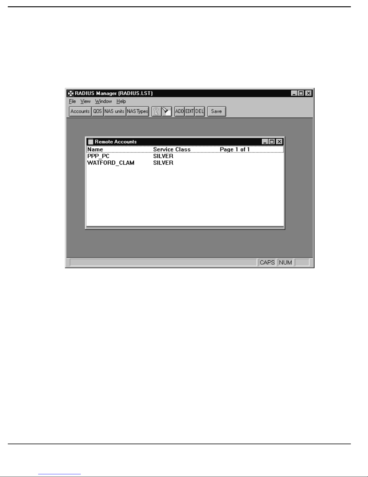
[Click] the Accounts button to access the ACCOUNTS INFORMATION
form.
This is a summary of the Remote Accounts information.
To Edit an entry, highlight it and [click] the EDIT button to access the
relevant function.
To Add an entry, [click] the ADD button.
To Delete an entry, highlight it and [click]the DELETE button.
2-13
Page 32
R
EFERENCE
CCOUNT INFORMATION
A
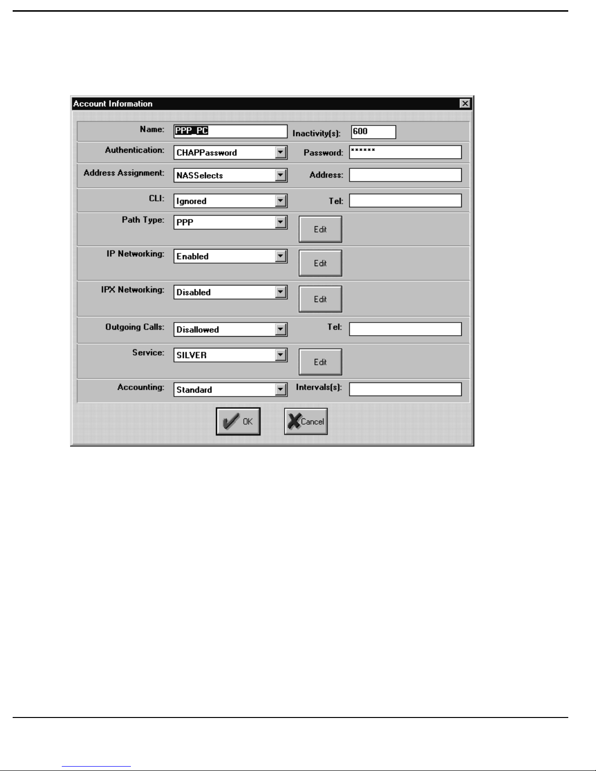
The Account Information forms defines the Remote Access Accounts by
name.
NAME The Name of the remote Account. It must be
[Click] on the NAME field and Type the {Name of your PC or CLAM}.
2-14
EXACTLY the same as that configured on the
device itself. (i.e. CLAM System Name,
LOGIN Name or User Name on a Windows
95 PC).
Page 33

R
EFERENCE
INACTIVITY This is the default minimum time in seconds
between allowed session timers.
[Click] on the INACTIVITY field and Type {a new default time in seconds}.
AUTHENTICATION There are three options, select from
AUTHENTICATION menu.
User Password This is the same as that on a single user
PC.
CHAP Password This is the CHAP SECRET on a PC or
Router.
No Authentication This is not recommended as it reduces the
level of security.
[Click] on AUTHENTICATION and Select {CHAP SECRET or USER
PASSWORD}.
PASSWORD [Click]the window and Type {The Exact
Password}.
Note: When typing Passwords, they must be EXACTLY the same for both
NAS Client and RADIUS, including Upper/Lower case.
ADDRESS ASSIGNMENT IP Addresses can be allocated on a dynamic
basis from Nautica NASs using the
ADDRESS POOLING facility on Nautica.
This is particularly useful when there is a high
level of contention from users dialling
occasionally into a site from single PCs using
integral ISDN terminal adapters, external
ISDN TAs or modems, using Windows 95.
Under these situations the Nautica NAS will
allocate the IP address to Authorised incoming
calls from a pool of available addresses. This
2-15
Page 34

R
EFERENCE
can reduce the number of IP Addresses needed
on an network of occasional users.
[Click] on the ADDRESS ASSIGNMENT field and select the required choice
from the list:
Don’t Care No Address Allocated. i.e. Each user
and/or site has already been allocated a
dedicated IP address.
NAS Selects The NAS (e.g. Nautica Marlin) provides
the IP address from the Address Pool.
Specific This allows the NAS to provide a Specific
Address for each incoming client.
ADDRESS Type{Specific Address to be allocated} (Only
IF Specific was selected).
CLI This provides for checking of the ISDN or
Telephone Number of the incoming call, using
the CLI (Calling Line ID in USA) standard
output from the local exchange.
Note: Due to regional variations, please check that this facility has been
enabled and operates for each incoming call prior to setting it as a
security level.
[Click] on the CLI field and select the options from:
Ignored CLI is ignored (Not recommended for
secure sites).
Exact Match An exact match with the CLI number is
2-16
required for access to the network.
Page 35

R
EFERENCE
Partial Match This allows a partial match of the CLI. It
allows for instances where variations in
Area Code occur when calls arrive via
different exchanges.
TEL Type {ISDN Number or Telephone Number}
to be matched for CLI checking.
ATH TYPE
P
Three Path options are provided.
[Click] on the PATH TYPE window and select from the following drop-down
list:
PPP Standard PPP or ML-PPP connections,
using either PAP or CHAP security.
Nautica Nautica Paths (Recommended for all
Nautica-Nautica connections).
Undistinguished This filed allows Nautica RADIUS to be
used in conjunction with other
manufacturers systems which may not
fully conform to either the RADIUS
standard or operate link level protocols
which vary from the standard
PPP/PAP/CHAP.
Note: Nautica Paths are proprietary to “Nautica to Nautica” connections.
They include optional data compression and accelerated call set-up
times, especially for Multi-link applications, enhanced security and
ISDN budgeting options.
To Edit or Add a Path after selecting the PATH TYPE [click] the EDIT
button.
2-17
Page 36

R
EFERENCE
ULTI-LINK OPERATION
M
(PPP
OR NAUTICA PATHS
)
To allow multiple ISDN B-Channels to be combined into a single datastream
(i.e. Multi-Linking), Nautica RADIUS provides two options:
MULTI-LINK NAUTICA This is recommended for all Nautica to
Nautica connections as it provides for a more
rapid call connection time. It allows data to
be transmitted across the first ISDN
connection whilst the additional connections
are being established and has the added
benefit of allowing the use of data
compression and dynamic load balancing
using packet fragmentation and
recombination.
MULTI-LINK PPP This operates in standard ML-PPP mode
(RFC1717 and 1990) and allows connectivity
to any other vendors device supporting the
above mentioned RFCs.
To configure the options for Multi-Link Operation [click] the EDIT button.
2-18
Page 37
R
EFERENCE
ULTI-LINK NAUTICA
M
/PPP
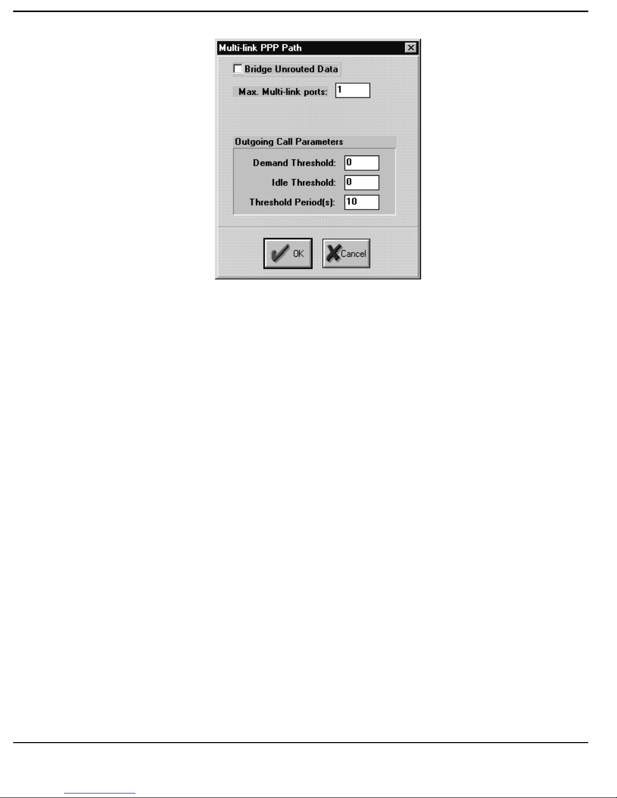
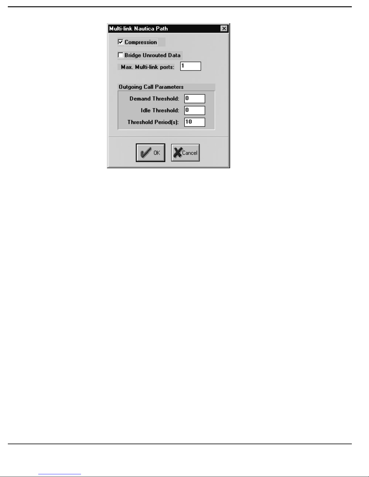
COMPRESSION [Click] to enable Data Compression on this
path.
BRIDGE [Click] to enable transparent bridging (option
not available on version 3.xx Router
software).
MAX MULTI-LINK PORTS Enter the maximum number of Multi-Link
channels available for this path.
DEMAND THRESHOLD Enter the percentage Link utilisation necessary
to trigger an additional ISDN connection. (e.g.
Type {70})
IDLE THRESHOLD Enter the percentage Link utilisation necessary
to trigger the termination of each additional
THRESHOLD PERIOD Enter the sampling period (in seconds) that
ISDN connection. (e.g. Type {30})
should be used in order to determine whether
both the Idle and Demand Thresholds have
been met.
2-19
Page 38
R
EFERENCE
2-20
Page 39

R
EFERENCE
NDISTINGUISHED
U
(OEM NAS P
RODUCT CONNECTIONS TO
RADIUS)
UNDISTINGUISHED Select this item where another manufacturers’
NAS is to be used with Nautica RADIUS.
[Click] the ADD button to add the attributes of the OEM product.
[Click] the EDIT button to Edit the attributes of the OEM product.
ATTRIBUTE NUM Enter the attribute numbers provided by the
OEM manufacturer in accordance with the
RADIUS published specification.
[Click] on the required option to select the formatting of this field :
INTEGER
STRING
OCTET
VALUE Type {The Value of the Attributes in the
Specification from the OEM}.
2-21
Page 40
R
EFERENCE
ETWORKING
IP N
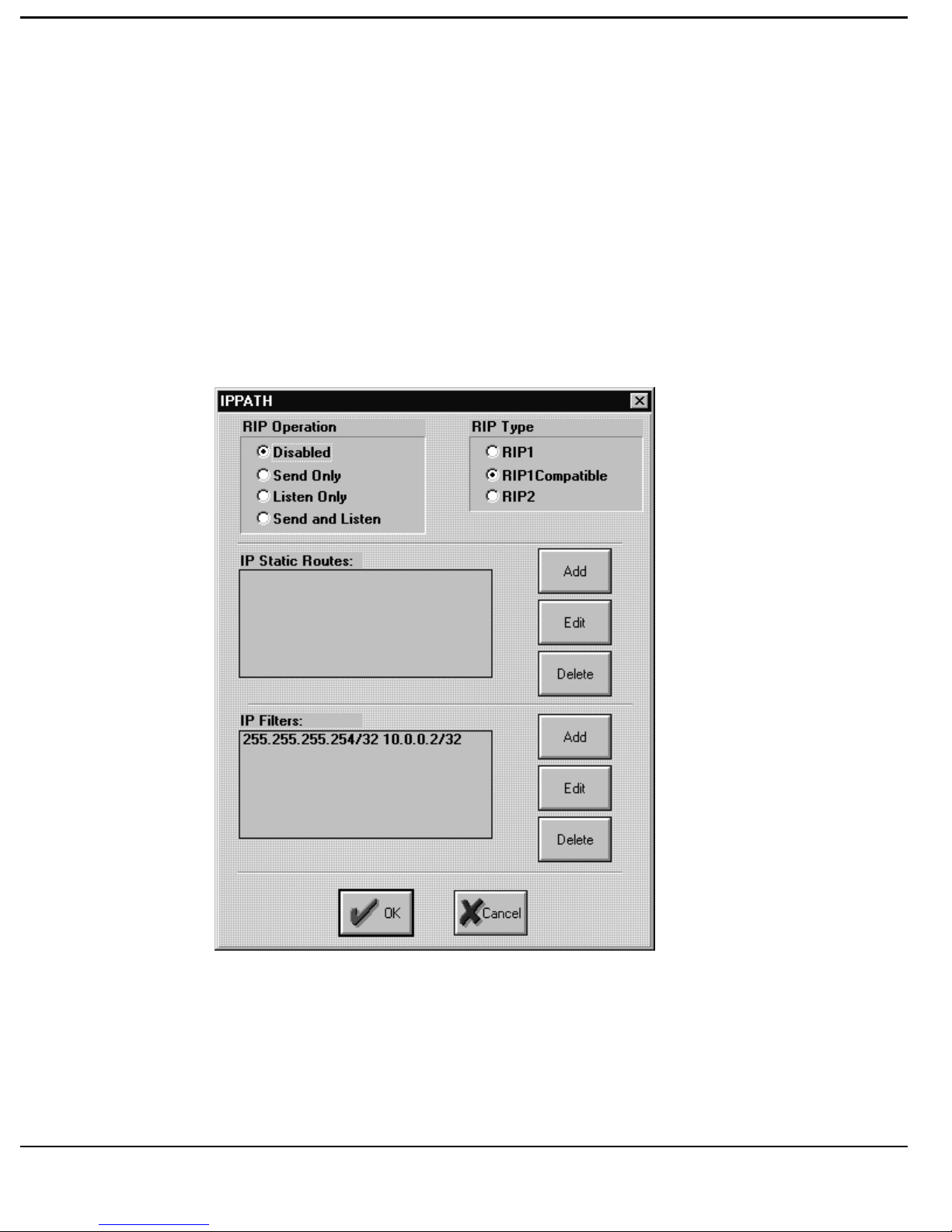
There are two options for this field:
Enabled
Disabled
To Add or Edit IP NETWORKING, Select ENABLED then [click] EDIT.
[Click] on each relevant item in order to select it:
2-22
Page 41

R
EFERENCE
RIP O
PERATION
Select one of the options below:-
DISABLED RIP is disabled.
SEND ONLY The NAS (e.g. Marlin) broadcasts RIP tables,
but does not accept RIP broadcasts.
LISTEN ONLY The NAS accepts RIP broadcasts but does no
transmit RIPs to the remote site.
SEND & LISTEN The NAS both transmits and receives RIP
broadcasts.
Note: If RIP is disabled
Static routes must be set up for each connection.
RIP T
YPE
RIP 1 Sets RIP 1 as the standard routing information
update protocol.
RIP 1 COMPATIBLE Sets routing for RIP1 compatibility on the
interface, with RIP 2 addressing on the
network. This allows non standard subnet
information to be passed onto those devices
that can process it.
RIP 2 Sets the standard routing as RIP 2, allowing
the increased security of specific subnet
transmission to remote sites.
2-23
Page 42

R
EFERENCE
TATIC ROUTE TABLES
S
Static Route Tables are used to restrict access on an account by account basis.
This feature will increase security by restricting access to resources and
facilities on all of your network, parts of the network or to specific IP
addresses only.
To Add a Static Route for a path [click] the ADD button.
To Edit a Static Route for a path [click] the EDIT button.
To Delete a Static Route for a path, [click] on the path to highlight it and
[click] the DELETE button.
REMOTE IP SUBNET Type {the IP Address} of the remote unit in
the window.
IP FILTER To Add a IP Filter for a path [click] the ADD
button.
Note: If no entry is made in these tables, the entire network will be
accessible to all Authenticated connections from the particular path.
If only one address/or filter is entered that will be the limitation of
access.
Note: Filter pairs are treated on a Forward On Match basis and are only
associated with the Account they are configured on while the Session
is active.
To Edit a IP Filter for a path [click] the EDIT button.
IP Address1/Mask Type { Source IP Address/Subnet Mask}.
IP Address2/Mask Type {Destination IP Address/Subnet Mask}.
To Delete a IP Filter for a path, [click] on the path to highlight it and [click]
the DELETE button.
2-24
Page 43
R
EFERENCE
NETWORKING
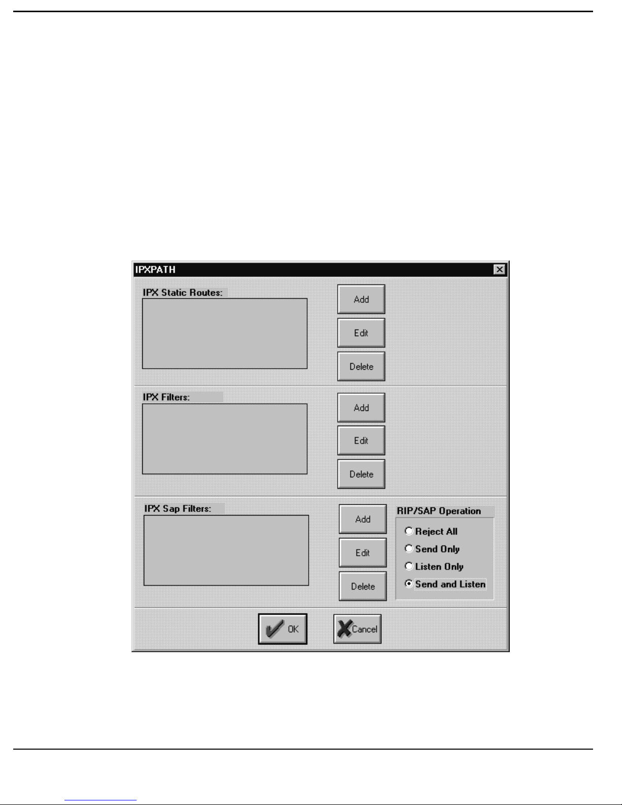
IPX
[Click] the required option to select either:
ENABLED where Netware IPX/SPX is to be routed.
DISABLED where IPX/SPX is not required.
To Add or Edit an IPX Path [click] the EDIT button.
2-25
Page 44

R
EFERENCE
IPX STATIC ROUTES Static routes can be added to establish secure
connections and limited access to facilities
from remote sites.
To Add an IPX Path [click] the ADD button.
To Edit an IPX Path [click] the EDIT button.
Insert the Address of the Remote Networks.
IPX NET FILTER IPX Network Traffic can be filtered. This
prevents access to certain routes, and
destinations.
Note: If no entry is made in these tables, the entire network will be
accessible to all Authenticated connections from the particular path.
If only one address/or filter is entered that will be the limitation of
access.
Note: Filter pairs are treated on a Forward On Match basis and are only
associated with the Account they are configured on while the Session
is active.
To Add a IPX Filter for a path [click] the ADD button.
To Edit a IPX Filter for a path [click] the EDIT button.
To Delete a IPX Filter for a path, [click] on the path to highlight it and [click]
the DELETE button.
IPX SAP FILTER IPX SAPs (Service Advertising Packets) can
be filtered. This prevents both access to and
2-26
knowledge of unauthorised addresses by
remote sites. It also reduces the transmission
overhead of the SAP broadcasts being sent to
a site.
Page 45

R
EFERENCE
To Add a IPX SAP Filter for a path [click] the ADD button.
To Edit a IPX SAP Filter for a path [click] the EDIT button.
To Delete a IPX SAP Filter for a path, [click] on the path to highlight it and
[click] the DELETE button.
Insert the Server Names where Access is Allowed from this path.
RIP/SAP OPERATION This facility adds further security protection
by limiting the transmission of RIP and SAP
frames across a path. [Click] on the selection
required from the list:-
Reject All Rejects all RIP and SAP frames, ONLY to
be used for static routes.
Send Only Only Sends RIPs and SAPs (Except where
specifically filtered). Needs Static Routes
to be established.
Listen Only Only accepts RIPs and SAPs, does not
broadcast them remotely. Needs Static
Routes to be established.
Send & Listen Broadcasts and Receives RIPs an SAPs,
except those filtered above. This allows
automatic learning of the addresses and
hence does not require Static Routes.
Note: If no entry is made in these tables, the entire network will be
accessible to all Authenticated connections from the particular path.
If only one address/or filter is entered that will be the limitation of
access.
UTGOING CALL SUPPORT
O
2-27
Page 46

R
EFERENCE
[Click] the items required to make your selection from the drop-down menu.
ALLOWED Outgoing Calls are allowed.
Type {Telephone or ISDN Number} in the window.
DISALLOWED No outgoing calls will be allowed.
ERVICE
S
Select from the drop-down menu the Quality of Service to be applied to this
Account.
Note: Only QOS entered into to the Grade Of Service are available.
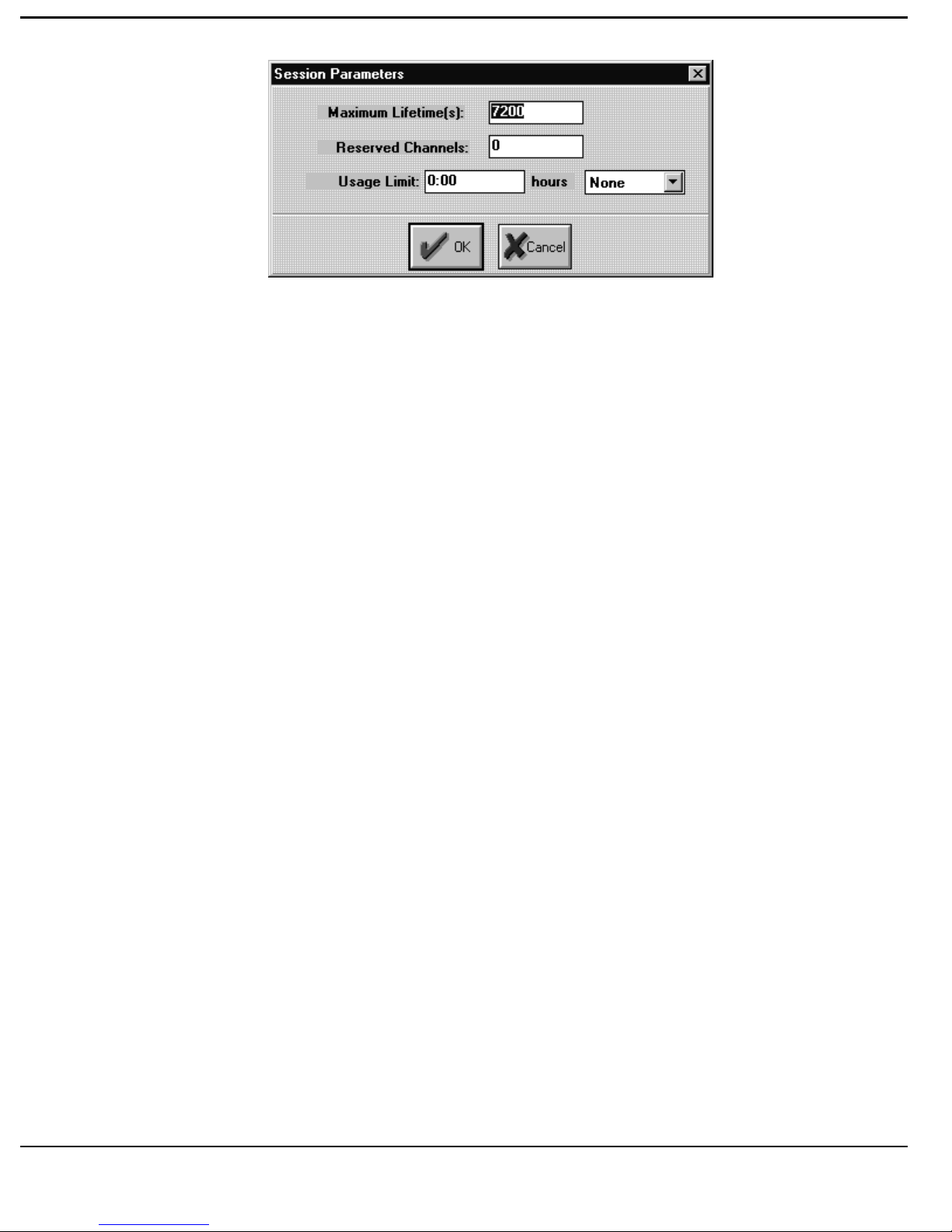
ESSION PARAMETERS
S
This allows additional restrictions to be added to an individual Quality of
Service for accounts.
Note: In the case of a mis-configuration of overlapping time bands, these
restrictions will terminate at the Earliest configured time.
To Edit the SESSION PARAMETERS [click] the EDIT button.
2-28
Page 47
R
EFERENCE
MAXIMUM LIFETIME This is the Maximum Lifetime in Seconds, of
a Session. The Default is 7200 seconds (2
hours).
To insert an alternative [click] on the window and Type {Time in Seconds}.
RESERVED CHANNELS This is the Minimum number of Channels
Reserved for a Session while a Session is live,
but may have the ISDN connection dropped.
The Default is 1.
To insert an alternative, [click] on the window and Type {Number of
Channels}.
USAGE LIMIT The amount of Time in Hours and Minutes, an
Account can access the network over a given
period of time.
To insert a period [click] on the window and Type {Time in Hours}.
To Select the period of measurement, [click] on the drop-down menu and
[click] the required choice from:
Day
Week
Month
2-29
Page 48

R
EFERENCE
CCOUNTING
A
[Click] on the option required:-
STANDARD Standard Accounting is by Start Call, Start
Session, End Call, End Session.
PERIODIC This category allows the accounting of leased
line services on a periodic basis, rather than a
call basis. Enter the Interval in Seconds for
posting the accounts collected on a Periodic
Account.
Note: having Configured Nautica RADIUS SAVE the Configuration.
2-30
Page 49
R
EFERENCE
g
RADIUS S
ERVER
The RADIUS Server program provides the real time Authentication and
Accounting functions described in Chapter 1. All Incoming and Outgoing
connection requests to or from the main Network are directed to the RADIUS
Server via the NAS Router. Consequently connections will only be vetted
when the RADIUS Server is up and running.
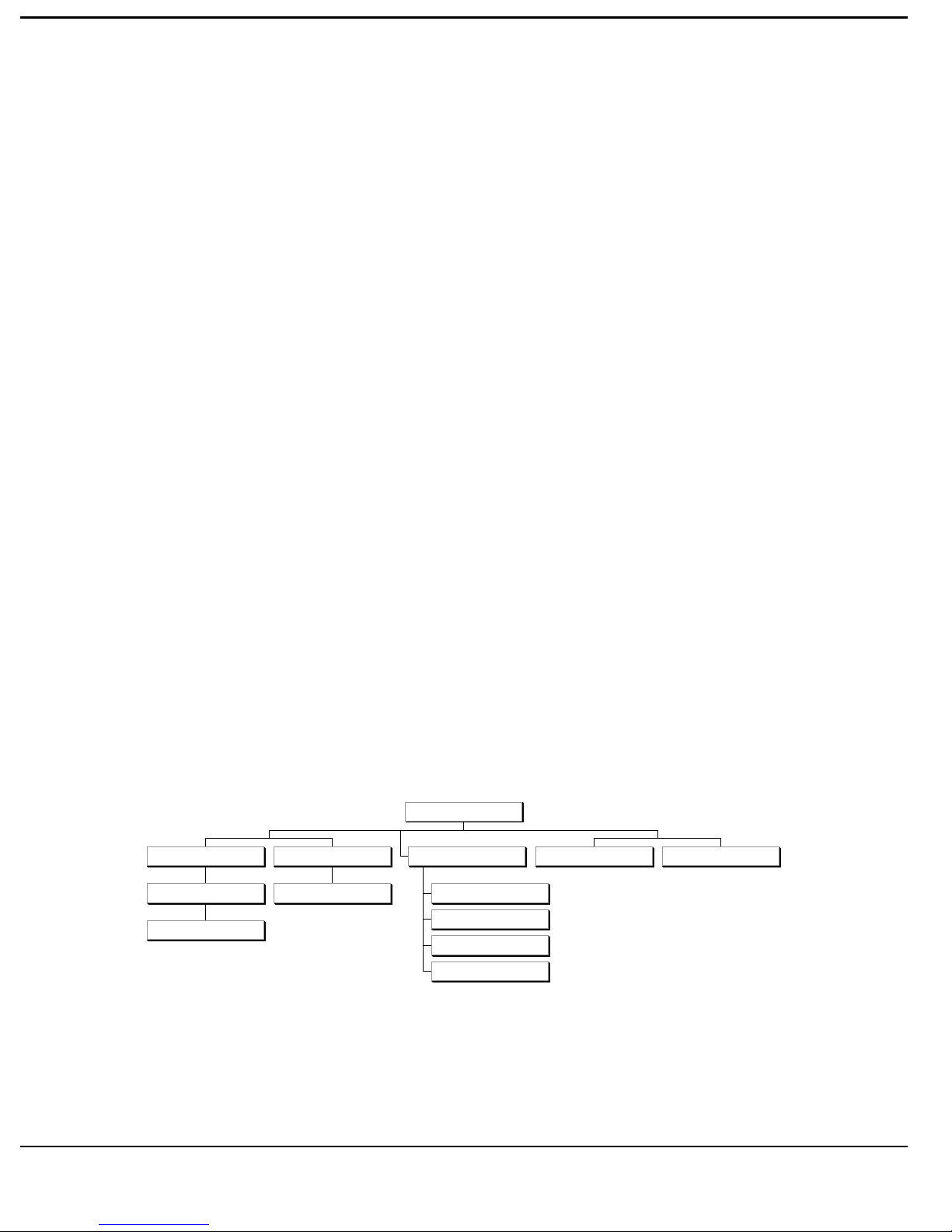
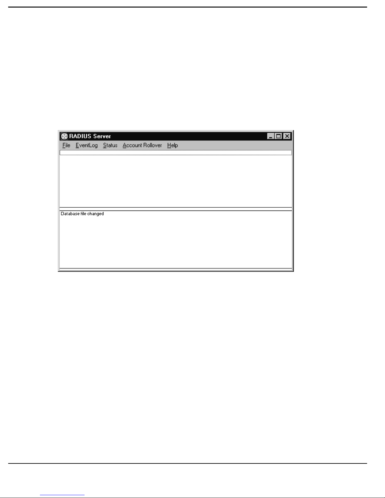
The RADIUS Server portion of Nautica RADIUS consists of a two part
window. The top half is the Status Window, the bottom half is a rolling Event
Log.
N
AUTICA
File
Configure
RADIUS Server Settings
RADIUS S
Event Lo
Event Log Control
ERVER MENU MAP
RADIUS Server
Status Acc oun t Rollover Help
QOS Status
Device Status
Account Status
Accoun t Allocation
2-31
Page 50
R
EFERENCE
F
ILE
To access the File form [click] on the File/Configure menu. This will allow
the configuration of RADIUS Server Settings.
RADIUS S
ERVER SETTINGS
LOCAL FILE This is the configuration file of the NAS
clients and users. It is usually called
RADIUS.LST.
SHARED FILE This is a second configuration file of NAS
client and user accounts. This can be a shared
file and may be located on another machine.
DATABASE FILE This can be selected from the following two
FORMAT choices
ASCII ASCII file format.
Optimised Reserved for future use. Do not Select.
2-32
Page 51

R
EFERENCE
Note: Both Files are loaded and viewed as one file by Nautica RADIUS
when Authenticating and Authorising access. Where distributed
RADIUS systems are used, the Shared File may be on a central
RADIUS system to provide for mobile users requiring occasional
access from remote parts of the network. Both files are regularly
polled for any changes, and in the event of a change being detected,
the new version of the file will be loaded. In a distributed system, this
polling takes place via attached Windows Network drives. Therefore
care must be taken to ensure that access to remotely sited RADIUS
systems is via a cost-effective connection system.
LOG ACCOUNTS Select this box to log accounts to your hard
disc drive.
ACCOUNTING FILE This details where Accounts are stored by
NAMES name of Account.
The default Accounting File Name string is shown below :-
ACCOUNT %-3.3s %s %s %d.CSV
The default string will produce a set of sequenced files starting from 1, similar
to the following :-
ACCOUNT Mon 0802 2359 1.CSV.
The file name is in the format [TEXT
composed of the following variables (a non text variable can be disabled by
inserting 0.0 between the %s e.g. %0.0s) :
Text
1
] %s1 %s2 %s3 %d[TEXT2]. It is
1
any printable characters with which you want to start
the file name.
2-33
Page 52

R
EFERENCE
%s
1
this variable defines how the day of the week is
displayed, a minus sign (-) forces left justification,
the number before the decimal point is the minimum
string length with the maximum following the
decimal point.
%s
%s
2
3
this variable outputs the date in U.S. format (mmdd).
this variable outputs the time in hhmm format.
%d this variable causes a sequence number to be
inserted which automatically increments from 1, a
reboot of the server will cause the sequence to restart
from 1.
.Text
2
use a decimal point followed by a text string to
indicate the file format.
ACCOUNT RECORD Select the required format for the output of
FORMAT Account records to an external processing
device or program.
INTERPRETED CSV The specified information fields are
extracted from the event log string and
presented and stored in the correct order in
CSV format.
RAW CSV The entire event log string is presented
and stored in CSV format.
RAW BINARY The entire event log string is stored as a
binary file. It is presented visually as an
interpreted field on the Event Log.
2-34
Page 53

R
EFERENCE
ACCOUNT DELIVERY This details the frequency of delivery of
FREQUENCY Account information to an external device.
Select from the options below:-
No Rollover No rollover of files without manual
intervention.
Every 30 Mins Rollover every 30 mins to a new file.
Every 1,2,6, 12 or 24 hours Rollover every (n) hours to a new file.
Midnight Rollover at midnight to a new file.
Sunday Midnight Rollover at midnight every Sunday to a
new file.
Note: The frequency of Account collection should be set in relation to the
level of network activity, the location of the Nautica RADIUS Server
compared with the Account processor and the importance of
accounting integrity.
2-35
Page 54

R
EFERENCE
E
VENT LOG
This details each event in the history of the Nautica RADIUS operation.
There are few options to configure as this device is an aid to diagnosis of
problems, and a means of directly observing access activity.
[Click] on “Eventlog” and select from the menu:
Eventlog/Freeze This freezes the Event Log so that it does not
print events. In a heavily used RADIUS
Server site, Freezing the Event Log can
increase performance of the Server.
Eventlog/Run The Default is for this to be set, and the Event
Log to Run.
Eventlog/Save This allows the Event Log to be saved to a file
specified in the Window.
2-36
Page 55
R
EFERENCE
S
TATUS
EVICE STATUS
D
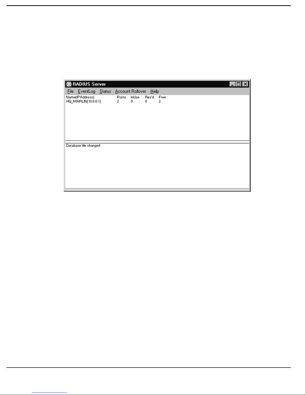
This window provides a view of the Status of each NAS device and Remote
device in use. [Double clicking] the top line of the screen will refresh all
items in the display from the Local Database. [Double click] the Device to
refresh the selected item with information currently held in the RADIUS
Client.
Ports Total number of ports available on the Device.
In Use Total Number of channels (or ports for leased
lines) in use on the Device.
Res’d Number of channels reserved on the NAS due
to live sessions, or minimum access
reservation levels.
Free Number of Free channels.
2-37
Page 56
R
EFERENCE
QOS S
TATUS
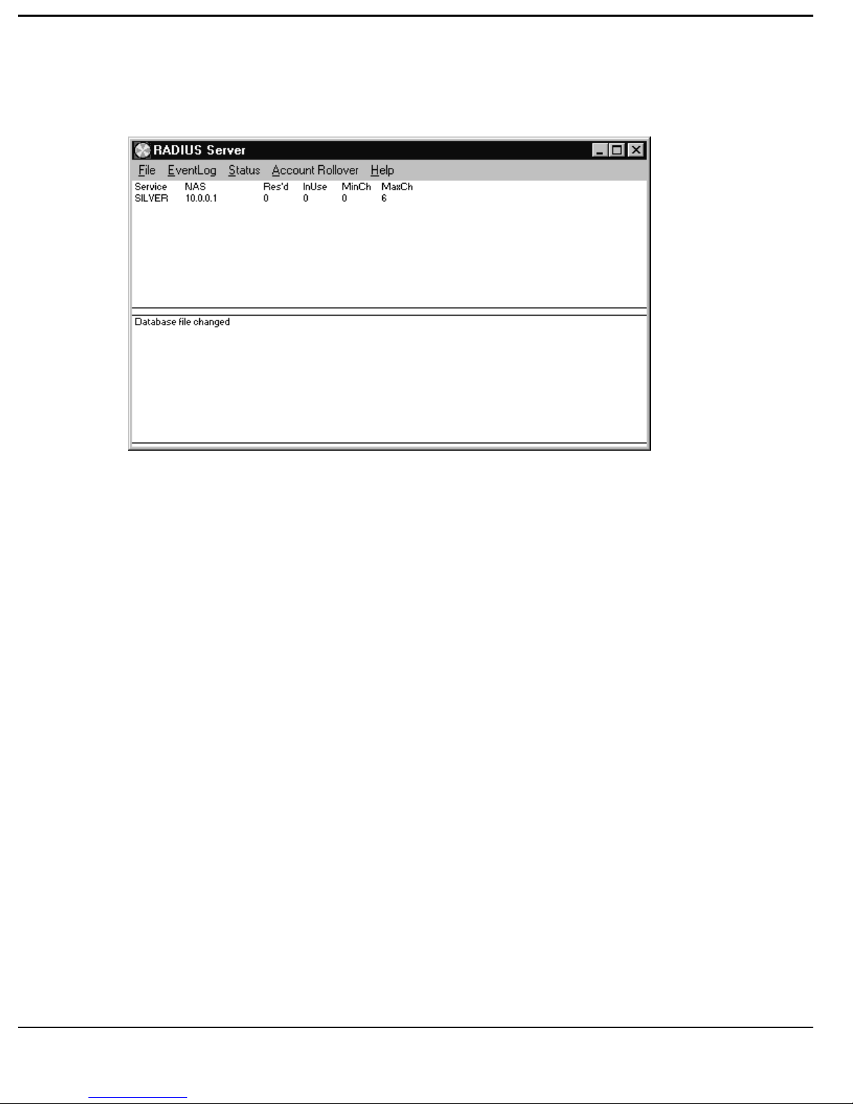
Service This is the Quality of Service Name.
NAS This is the Name of the NAS using the QOS.
Res’d This details how many channels are Reserved
for that QOS.
In Use Details the number of Channels in Use.
Mn Ch Details the Minimum number of channels
allowed.
Max Ch Details the Maximum number of channels
allowed.
2-38
Page 57
R
EFERENCE
ACCOUNT STATUS
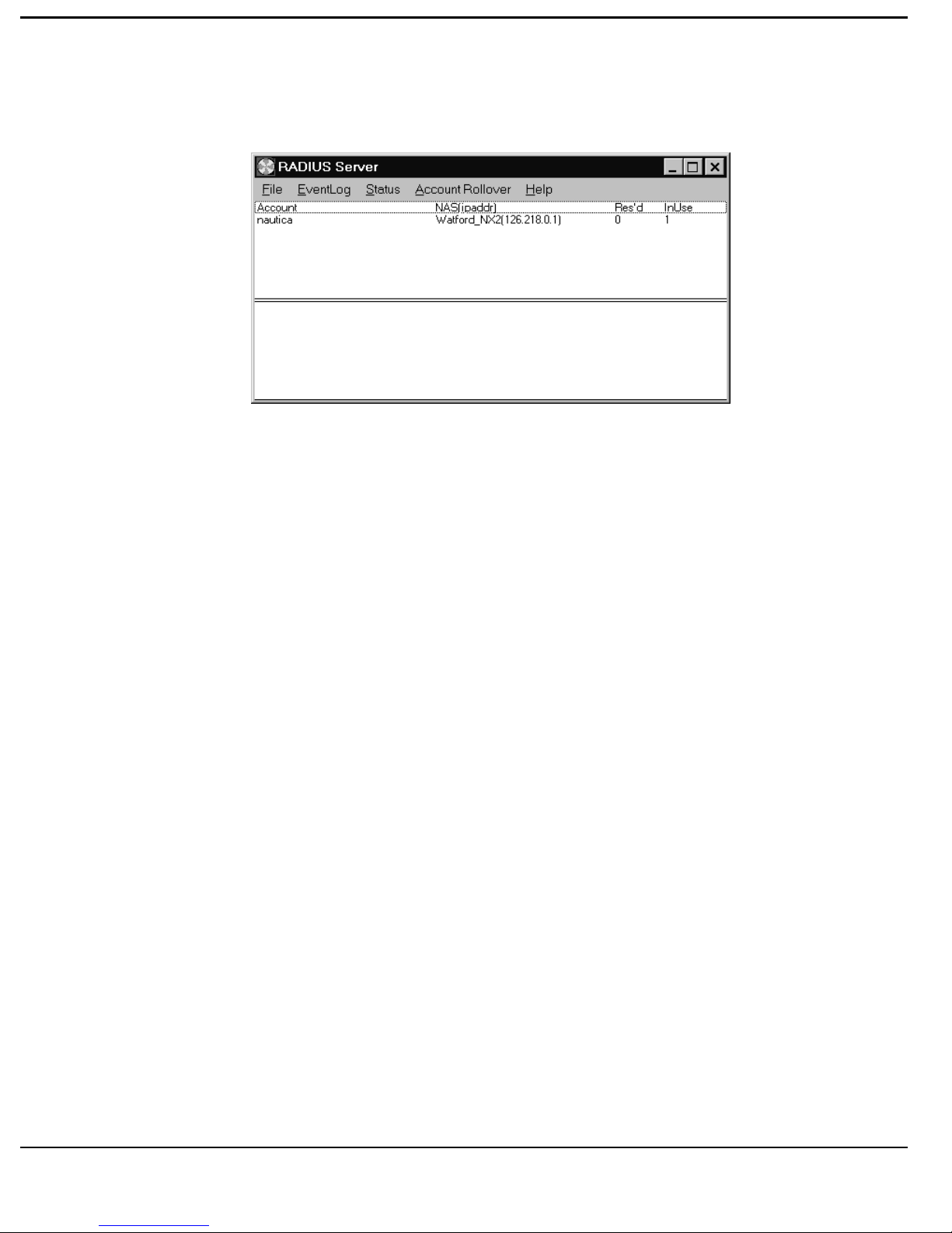
This window shows the current status of Accounts connected through
RADIUS, and is refreshed by [double clicking] the top line of the screen.
Account The Account Name.
NAS(IP Add) The NAS IP Address that is being accessed by
the Account.
Res’d Number of channels reserved when a session
is idle, or being spoofed.
InUse Number of Channels actually in use by the
Account.
2-39
Page 58
R
EFERENCE
CCOUNT ALLOCATION
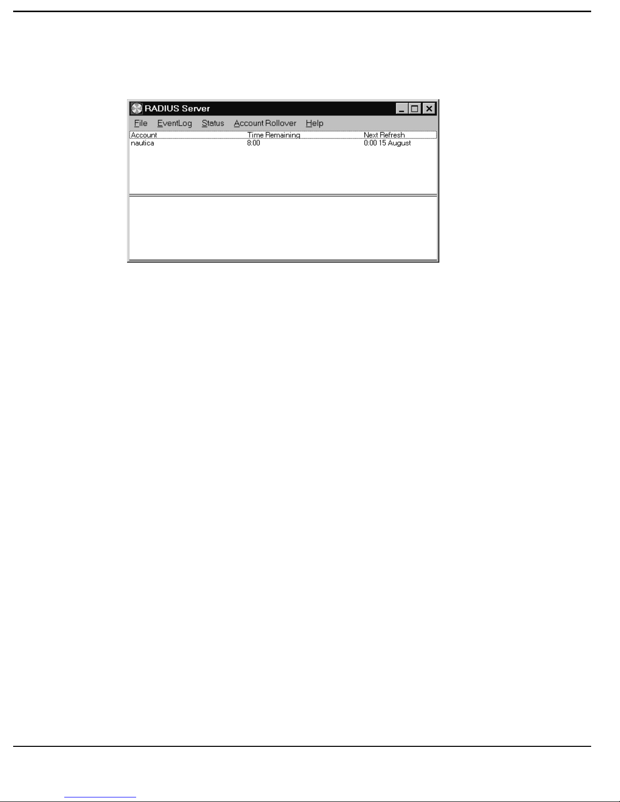
A
This window indicates the Accounts Logged on at any given time, and how
much time each has left in their Account, and is refreshed by [double clicking]
the top line of the screen.
Allocated time can be increased by [double clicking] the appropriate Account.
Account Account Name.
Time Remaining Time remaining to use the Account.
Next Refresh Next Time/Date Account Time is refilled.
A
CCOUNT ROLLOVER
[Click] the Account Rollover Menu Bar to select the periodicity of the
creation of the follow-on file.
2-40
Page 59

R
EFERENCE
E
VENT LOG WINDOW
There are 4 main categories of Event Log messages:[SEC] Security - Who is trying to access the network and the results.
[ACC] Accounting - Details of successful individual connections and
sessions.
[ROU] Routing requests for outgoing connections.
[INFO] Other Information.
Breakdown of Account Records
All “RAW Comma Separated Variable” accounting records use a common
format in both the Event Log window (the lower of the two windows) and the
designated Log file. A record consists of a number of fields separated by
commas. If there is no information for a variable nothing is placed in that
variables field. This produces variable length records. The length of the
record being primarily dependant on the “Record Type” (i.e. Open, Close,
Session Start, Session Stop and Periodic).
An example of an Account Record is shown on the next page. The breakdown
of the message format is also shown. The field values are listed below.
Service Type: 2= Router.
Authentication Method: 1=RADIUS, 2=Local.
Record Type: 1=Open, 2=Close, 3=Session start, 4=Session stop, 5=Periodic.
Port Type: 1=Ethernet, 2=WAN, 3=ISDN, 4=Frame Relay, 5=Modem.
Direction of connection: 1=In, 2=Out, 3=WAN.
2-41
Page 60

R
EFERENCE
Protocol ID (in decimal) requesting connection: e.g. 2048==0x0800==IP.
Date/Time in U.S. format recorded by RADIUS Server.
Seconds waiting to send packet to Server from RADIUS
Client.
Dial In User Account Name.
RADIUS Client IP Address.
Service Type.
RADIUS Client Name.
Authentication Method.
[ACC],07/31/96 10:58:22,0,WATFORD_CLAM,10.0.0.1,2,HQ_MARLIN,1,
CC000008,1,3,CC000008CC000009,1,1,1,0,,0,0,0,0,0,01923123456,
ISDN number.
Duration in seconds.
Packets Out (non-idle).
Packets In.
Bytes Out.
Bytes In (User to RADIUS Client).
IP address requesting connection.
Protocol requesting connection.
Direction of connection.
Connection ID (first half is Session ID).
Port type.
Record Type.
2-42
Connections.
Channels Reserved.
Page 61

R
EFERENCE
Session ID (first 2 hex characters show the number of client start-ups).
Example Event Log for an Incoming Connection.
The remote user (Clam) is called WATFORD_CLAM the RADIUS
Client(NAS)/Server is at HQ.
Note: In the following paragraphs some lines have been wrapped in order to
fit the page. Lines preceded by “*” are comments.
[SEC]Access-Request NAS=HQ_MARLIN Account=WATFORD_CLAM
*User WATFORD_CLAM attempts access to HQ_MARLIN Site.
[SEC],07/31/96 10:58:22,Matched Nautica Key OK, WATFORD_CLAM
*Passwords are OK.
[SEC],07/31/96 10:58:22,Access-Accept NAS=HQ_MARLIN,
Account=WATFORD_CLAM, CLI=01923123456, t=28596
*Welcome (t = time in sec this access is valid).
[ACC],07/31/96 10:58:22,0,WATFORD_CLAM,10.0.0.1,2,
HQ_MARLIN,1,CC000008,3,0,CC0000080,1,0,
*This session has started.
[ACC],07/31/9610:58:22,0,WATFORD_CLAM,10.0.0.1,2,HQ_MARLIN,
1,CC000008,1,3,CC000008CC000009,1,1,1,0,,0,0,0,0,0,01923123456,
*First incoming connection has started.
[ACC],07/31/96 10:58:43,0,WATFORD_CLAM,10.0.0.1,2,
HQ_MARLIN,1,CC000008,2,3,CC000008CC000009,1,0,0,0,,37,37,1,1,20,
*The first connection closes 20 seconds later.
[SEC]Access-Request NAS=HQ_MARLIN Account=WATFORD_CLAM
2-43
Page 62

R
EFERENCE
*A second incoming connection for this session has arrived.
[SEC],07/31/96 10:59:20,Matched Nautica Key OK, WATFORD_CLAM
[SEC],07/31/96 10:59:20,Access-Accept NAS=HQ_MARLIN,
Account=WATFORD_CLAM, CLI=01923123456, t=28596
[ACC],07/31/96 10:59:20,0,WATFORD_CLAM,10.0.0.1,2,HQ_MARLIN,
1,CC000008,1,3,CC000008CC00000A,1,1,1,0,,0,0,0,0,0,01923123456,
[ACC],07/31/96 10:59:40,0,WATFORD_CLAM,10.0.0.1,2,HQ_MARLIN,
1,CC000008,2,3,CC000008CC00000A,1,0,0,0,,78,55,3,2,20,
*The second incoming connection has finished.
[ACC],07/31/96 11:02:27,0,WATFORD_CLAM,10.0.0.1,2,HQ_MARLIN,
1,CC000008,4,0,CC0000080,0,0,0,0,,115,92,4,3,243,
*Ten minutes later the session closes.
The RADIUS server can optionally be configured to output the Event Log in
the “Interpreted Comma Separated Variables” format. This restricts the
amount of information given but is easier to read.
Again this is an incoming connection:-
[SEC]Access-Request NAS=HQ_MARLIN Account=WATFORD_CLAM
[SEC],07/31/96 14:47:03,Matched Nautica Key OK, WATFORD_CLAM
[SEC],07/31/96 14:47:03,Access-Accept NAS=HQ_MARLIN,
Account=WATFORD_CLAM, CLI=01923123456, t=18777
2-44
Page 63

R
EFERENCE
[ACC],07/31/96 14:47:03,0,SessOpen,CC00000B,0,HQ_MARLIN
(10.0.0.1),WATFORD_CLAM(),,,,,
[ACC],07/31/96 14:47:03,0,ConnOpen,CC00000B,CC00000C,
HQ_MARLIN(10.0.0.1),WATFORD_CLAM(01923123456),0,0,0,0,0
[ACC],07/31/96 14:47:24,0,ConnClose,CC00000B,CC00000C,
HQ_MARLIN(10.0.0.1),WATFORD_CLAM(),20,36,37,1,1
[ROU],07/31/96 14:54:07,Route Setup (192.168.0.2): Best NAS =
HQ_MARLIN,
Requesting NAS = HQ_MARLIN, Account = WATFORD_CLAM
[ACC],07/31/96 14:54:07,0,SessOpen,00000005,0,
HQ_MARLIN(10.0.0.1.218.0.1),WATFORD_CLAM(),,,,,
[SEC]Access-Request NAS=HQ_MARLIN Account=WATFORD_CLAM
[SEC],07/31/96 14:54:09,Matched Nautica Key OK, WATFORD_CLAM
[SEC],07/31/96 14:54:09,Access-Accept NAS=HQ_MARLIN,
Account=WATFORD_CLAM,CLI=, t=18351
[ACC],07/31/96 14:54:09,0,ConnOpen,00000005,00000006,HQ_MARLIN
(10.0.0.1),WATFORD_CLAM(123456),0,0,0,0,0
[ACC],07/31/96 14:54:30,0,ConnClose,00000005,00000006,HQ_MARLIN
(10.0.0.1),WATFORD_CLAM(),20,92,90,3,3
[ACC],07/31/96 14:57:12,0,SessClose,00000005,0,HQ_MARLIN
(10.0.0.1),WATFORD_CLAM(),182,92,90,3,3
2-45
Page 64

R
EFERENCE
Example Event Log for an Outgoing Connection.
*We now attempt an outgoing connection via the user WATFORD_CLAM IP
address 192.168.0.2:-
[ROU],07/31/96 11:21:56,Route Setup (192.168.0.2): Best NAS =
HQ_MARLIN, Requesting NAS = HQ_MARLIN, Account =
WATFORD_CLAM
*RADIUS has found a path to 192.168.0.2 via WATFORD_CLAM.
[ACC],07/31/96 11:21:56,0,WATFORD_CLAM,10.0.0.1,2,HQ_MARLIN,
1,000000B4,3,0,000000B40,0,0,
*The session has started.
[SEC]Access-Request NAS=HQ_MARLIN Account=WATFORD_CLAM
*The connection is being made.
[SEC],07/31/96 11:21:58,Matched Nautica Key OK, WATFORD_CLAM
*Password OK.
[SEC],07/31/96 11:21:58,Access-Accept NAS=HQ_MARLIN,
Account=WATFORD_CLAM, CLI=, t=28353
*Go ahead.
[ACC],07/31/96 11:21:58,0,WATFORD_CLAM,10.0.0.1,2,HQ_MARLIN,
1,000000B4,1,3,000000B4000000B5,1,1,2,2048,10.0.0.2.0.0.23,
0,0,0,0,0,123456,
*Start of connection.
[ACC],07/31/96 11:22:19,0,WATFORD_CLAM,10.0.0.1,2,HQ_MARLIN,
1,000000B4,2,3,000000B4000000B5,1,0,0,0,,108,107,4,4,20,
2-46
Page 65

R
EFERENCE
*End of connection.
[ACC],07/31/96 11:25:02,0,WATFORD_CLAM,10.0.0.1,2,
HQ_MARLIN,1,000000B4,4,0,000000B40,0,0,0,0,,108,107,4,4,183,
*The session finishes.
2-47
Page 66

R
EFERENCE
2-48
Page 67

T
UTORIAL
N
AUTICA
RADIUS T
UTORIAL
The following scenarios are covered in this tutorial :-
Remote Access from a CLAM to a Nautica NAS
Remote Access from a Single PC User to a Nautica NAS
Outgoing Call Security via RADIUS
IP Connectivity
IP Filtering via RADIUS
IPX Connectivity
IPX Filtering via RADIUS
IPX SAP Filtering via RADIUS
Bandwidth on Demand
Quality Of Service
3-1
Page 68
T
UTORIAL
O
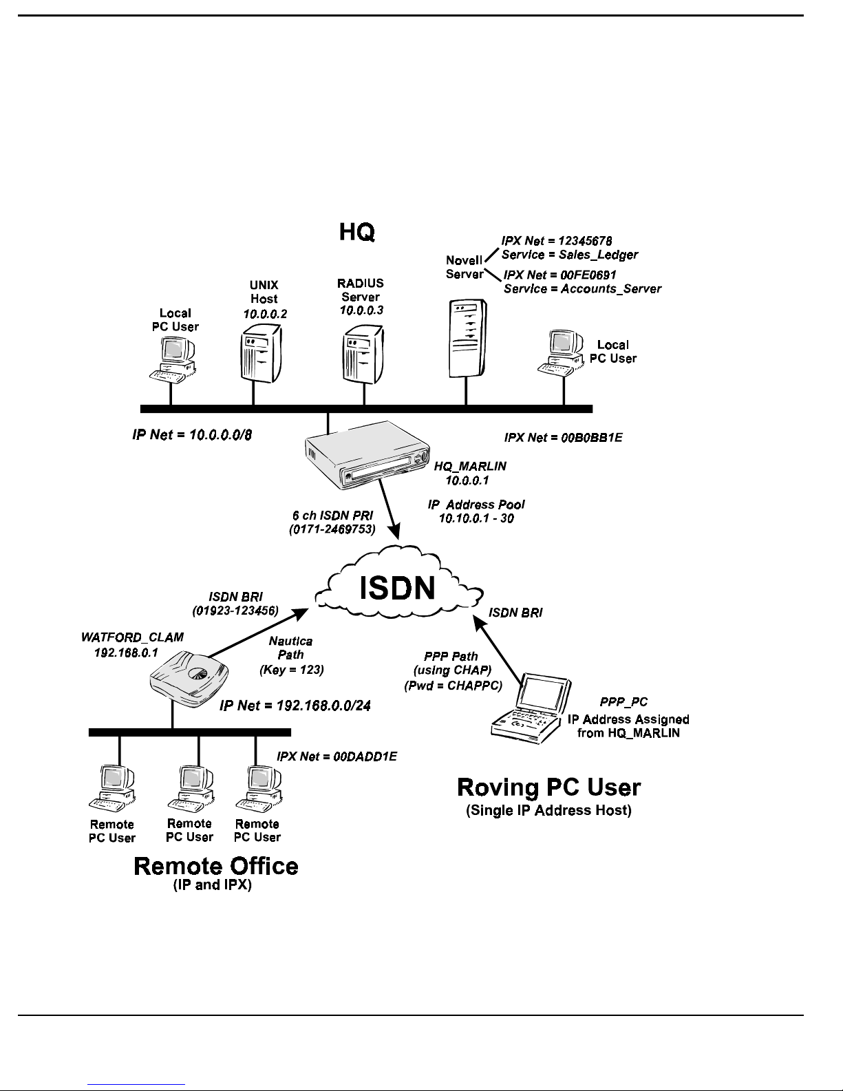
VERVIEW OF SAMPLE TEST NETWORK
The following tutorial explains how to configure both the Routers and the
RADIUS Security Server associated with the Network shown below.
3-2
Page 69

T
UTORIAL
As can be seen from the above diagram, the Tutorial Network comprises of a
main H.Q. LAN, a remote office with its own LAN, and a single “Roving
User” who has a Laptop PC running Windows 95 with integral ISDN
Terminal Adapter. Both the ISDN PRI at the HQ and the ISDN BRI line at
the remote office have the CLI feature enabled.
The main LAN has with an IP address of 10.0.0.0 and a subnet mask of /8
[255.0.0.0]. The main IP devices on the H.Q. LAN are a UNIX Host, with an
IP address of 10.0.0.2, a RADIUS Server, with an IP address of 10.0.0.3, and a
Nautica Marlin Router, with an IP address of 10.0.0.1. The Nautica Marlin
Router provides access to the H.Q. LAN for both the remote office and the
“Roving User” via a 6 channel ISDN PRI line. A Novell 4.x Server is located
on the main LAN. The Novell Server is running Frame Type 802.3 and has an
external Network Number of “00B0BB1E” and internal Network Numbers of
“00FE0691” and “12345678”. The Novell Server running two programs, one
of which is an Accounts package running on Network Number “00FE0691”,
the other is a Sales Ledger package running on internal Network Number
“12345678”.
The remote office LAN consists of PC’s and workstations that require to
connect to both the UNIX host and the Novell Accounts package on the H.Q.
LAN. The remote LAN has an IP address of 192.168.0.0 and a subnet mask
of /24 [ 255.255.255.0]. Access to the H.Q. LAN is provided by a Nautica
CLAM Router and an ISDN BRI line. The IP address of the CLAM is
192.168.0.1. The IPX Network Number of the remote office LAN is
“00DADD1E” and the IPX frame type is Ethernet Type II. As the Remote
Office LAN uses a Nautica Router to connect to another Nautica Router on
the H.Q. LAN the best communication protocol to use between the two sites is
the proprietary Nautica HDLC protocol.
The “Roving User” wishes only to connect to the UNIX Host. The IP Address
allocated to the “Roving User” is allocated from an IP Address Pool on the
H.Q. Marlin. The IP Address Pool used in this example contains IP addresses
which are part of the H.Q. LAN subnet, and range from 10.10.0.1 to
10.10.0.30. As the “Roving User” uses a PC which runs Windows 95 and an
integral ISDN TA to connect to the Nautica Router on the H.Q. LAN the best
communication protocol to use between the two is PPP (Point to Point
Protocol).
3-3
Page 70

T
UTORIAL
RADIUS C
The following tutorial assumes that neither the RADIUS Server or the
RADIUS Manager programs have ever ran on the Windows 95 PC before.
Please note that if the RADIUS Server and Manager programs are already
running or have ever ran in the past you may only need to amend the existing
RADIUS configuration to suit your new requirements. If you need to add
additional NAS types, NAS units, Quality Of Service profiles or an Accounts
then follow the relevant section in the tutorial.
Also included at the end of the tutorial are instructions on how to configure
the Nautica Routers used in the tutorial example.
ONFIGURATION TUTORIAL
3-4
Page 71

T
UTORIAL
RADIUS I
If the RADIUS server is up and running skip this section and move onto the
“RADIUS Configuration” section. The RADIUS Server and the RADIUS
Manager suite of programs is provided on two 3.5" Floppy Disks. These are
labelled “Disk 1” and “Disk 2”.
1. Place the 3.5" Floppy Disk labelled Disk 1 into the A Drive of the
Windows 95 PC.
2. Select the “Start” option on the Windows 95 Task Bar by placing the
mouse pointer over the “Start” Button and [clicking] the left mouse
button.
3. [Click] the “Run” option.
4. Type A:\Setup.exe in the “Open” box.
NSTALLATION
.
5. [Click] the OK Button.
6. Follow the instructions given in the Setup Windows and amend any
settings as necessary.
7. When the Setup program is complete the “Nautica RADIUS” Window is
displayed. [Double click] the red RADIUS_M icon in the “Nautica
RADIUS” Window.
8. When the “RADIUS Manager” window appears [click] the “Minimise”
Button. This will place the RADIUS Manager Button on the Task Bar.
9. [Double click] the green RADIUS_S icon in the “Nautica RADIUS”
Window.
10. When the “RADIUS Server” window appears [click] the “Minimise”
Button. This will place the RADIUS Server Button on the Task Bar.
11. [Click] the “Close” Button on the “Nautica RADIUS” Window.
3-5
Page 72

T
UTORIAL
C
ONFIGURATION PROCEDURE
The following sections will fully discuss the detailed configuration of the
Tutorial Sample Test Network. It is recommended that the configuration is
approached in the logical steps as defined below, and expanded on, in later
paragraphs.
Step 1 Configuration of the RADIUS Server.
1. The NAS Type configuration relates to the Hardware capabilities of the
NAS Router.
2. NAS Units allow specific configuration parameters to be assigned and
associated with each NAS Unit, i.e. the Units IP Address.
3. Before an Account can be configured the NAS Types and the NAS
Units must already have been defined.
4. The “Quality Of Service” Grades are used to control the availability of
the connection.
5. An “Account” contains parameters relating to an individual Dial-In user
or to a Remote Office LAN connected via Leased or Dial-In circuits. It
is also used to allocate the security, and to provide access restrictions by
using the already defined Quality Of Service Grades, associated with
the Account.
Step 2 Configuration of the NAS Router. (In this case a Nautica Marlin
Router)
Step 3 Configuration of the Remote Devices.
1. Any Remote Office LAN’s.
2. Any individual Dial-In users (Roving PC Users).
3-6
Page 73

T
UTORIAL
RADIUS M
The file RADIUS.LST holds the information database that the RADIUS
Server will use to Authenticate Users. To start the RADIUS Server in default
mode either delete this file, or if you want to keep the current configuration
rename the file to something else.
1. Configuring a NAS type.
1. If the RADIUS Manager Window is not already displayed on the screen
[click] the RADIUS Manager Button on the Task Bar.
ANAGER CONFIGURATION
2. [Click] the NAS types Button on the RADIUS Manager Toolbar. The
“Configured NAS Types (RADIUS clients)” window should appear.
3. [Click] the ADD Button to add a new NAS Device type to the list, or
select an existing NAS type and [click] the EDIT Button to edit the
configuration of the NAS Device type selected.
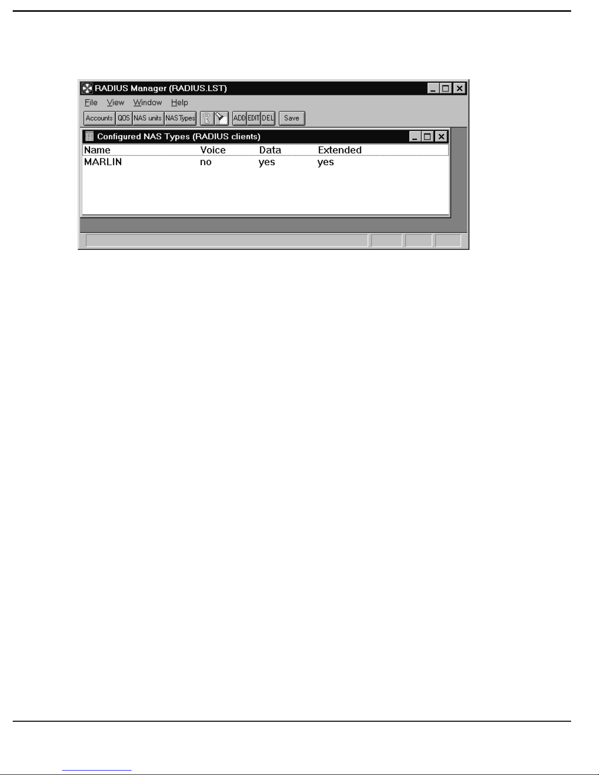
4. Add a new NAS Device type by entering a meaningful name in the
“Name:” box. Enter MARLIN in the Name Box.
5. Enable or disable the features supported by the NAS device by [clicking]
the various “Features Supported” options. Enable Data and Extended
Radius.
6. [Click] the OK Button to return you to the “Configured NAS types”
window when you have configured the appropriate options for this NAS
Device type.
3-7
Page 74
T
UTORIAL
The “Configured NAS types” screen should be as shown below.
7. [Click] the Save Button to save all changes made to the NAS types
profiles.
8. Close the “Configured NAS Types” window by [clicking] the Close
Button. The “RADIUS Manager (RADIUS.LST)” window should now be
displayed.
2. Configuring a NAS unit.
1. If the RADIUS Manager Window is not already displayed on the screen
[click] the RADIUS Manager Button on the Task Bar.
2. [Click] the NAS units Button on the RADIUS Manager Toolbar. The
“Configured NAS units (RADIUS clients)” window should appear.
3. [Click] the ADD Button to add a new NAS unit name to the list, or select
an existing NAS unit name and [click] the EDIT Button to edit the
configuration of the NAS unit name selected.
4. Add a new NAS unit name type by entering a meaningful name in the
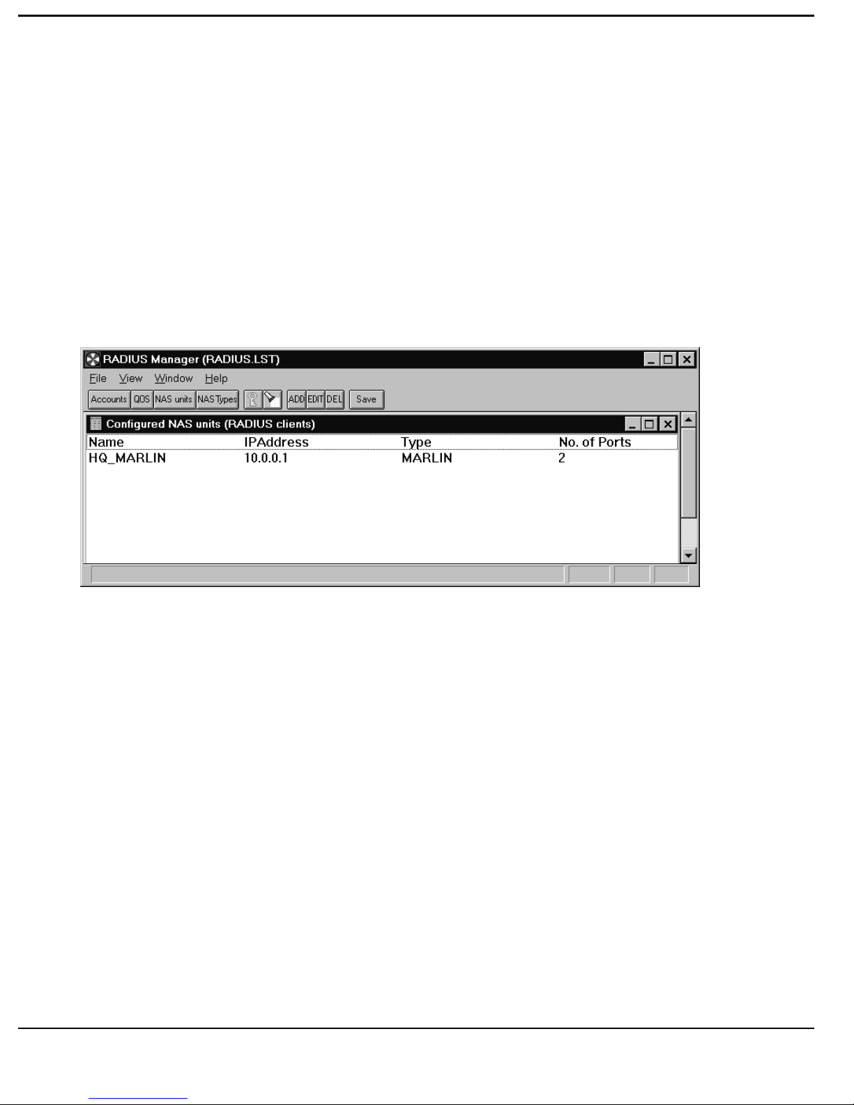
“Name:” box. Enter HQ_MARLIN the Name Box.
3-8
Page 75

T
UTORIAL
The NAS unit “Name” entered here does not have to correspond with the
associated NAS Router’s name [as configured in the Router’s System
Parameters Form (obtained by typing CO SY<CR> on the command line)].
The “Name” configured here is used by the RADIUS Server Event Log to
indicate which NAS Router the RADIUS Server is in communication with.
However for simplicity and to ease unit nomenclature we will assign the same
“Name” to the NAS unit as is defined in the HQ Marlin’s System Parameters.
5. Enter the IP Address of the associated NAS Router as applicable. In this
instance enter the IP Address of 10.0.0.1 in the IP Address Box.
6. Type the appropriate NAS type in the box provided, in this instance
MARLIN. This should correspond exactly with one of the NAS types
configured previously.
7. Alter the Number of Ports in accordance with the associated NAS
Router’s capabilities. For this example the Number of Ports should be set
to 6, as a 6 channel PRI module is installed in the Marlin located on the
HQ backbone network.
ISDN ports only should be taken into consideration, do not include any WAN
ports.
8. If the associated NAS Router is connected to a Nautica 8000 LSU then
[click] the “LSU Connected” option box. For this example do not select
this option.
9. Enter the Authentication code used between the RADIUS Server and the
associated NAS Router in the “Authentication” box. Enter PASSWORD
as the Authentication code.
An Authentication code must be entered. The Authentication code entered
here must be exactly the same as the password entered in the “Password” field
on the associated NAS Router’s RADIUS Configuration Parameters Form
(obtained by typing CO RA<CR> on the command line). The Authentication
code (Security Server Password) can be constructed from any printable
characters.
3-9
Page 76
T
UTORIAL
10. To alter the “Default Service” parameters [double click] the appropriate
option Box and enter the new value. For this exercise leave the Default
Service parameters at their default values.
The Default Service parameters are the values used by an Account User that
has not been allocated any Quality Of Service profiles. Refer to the Quality
Of Service section in this manual.
11. [Click] the OK Button to return you to the “Configured NAS units”
window when you have configured the appropriate options for this NAS
unit.
12. [Click] the Save Button to save all changes made to the NAS units
profiles.
13. Close the “Configured NAS units” window by [clicking] the Close
Button. The “RADIUS Manager (RADIUS.LST)” window should now be
displayed.
3. Configuring the Quality Of Service (QOS) Option
1. If the RADIUS Manager Window is not already displayed on the screen
[click] the RADIUS Manager Button on the Task Bar.
3-10
Page 77

T
UTORIAL
2. [Click] the QOS Button on the RADIUS Manager Toolbar. The “Quality
of Service” window should appear.
3. [Click] the ADD Button to add a new Grade of Service profile to the list,
or select an existing Service and [click] the EDIT Button to edit the
configuration of the Service Name selected.
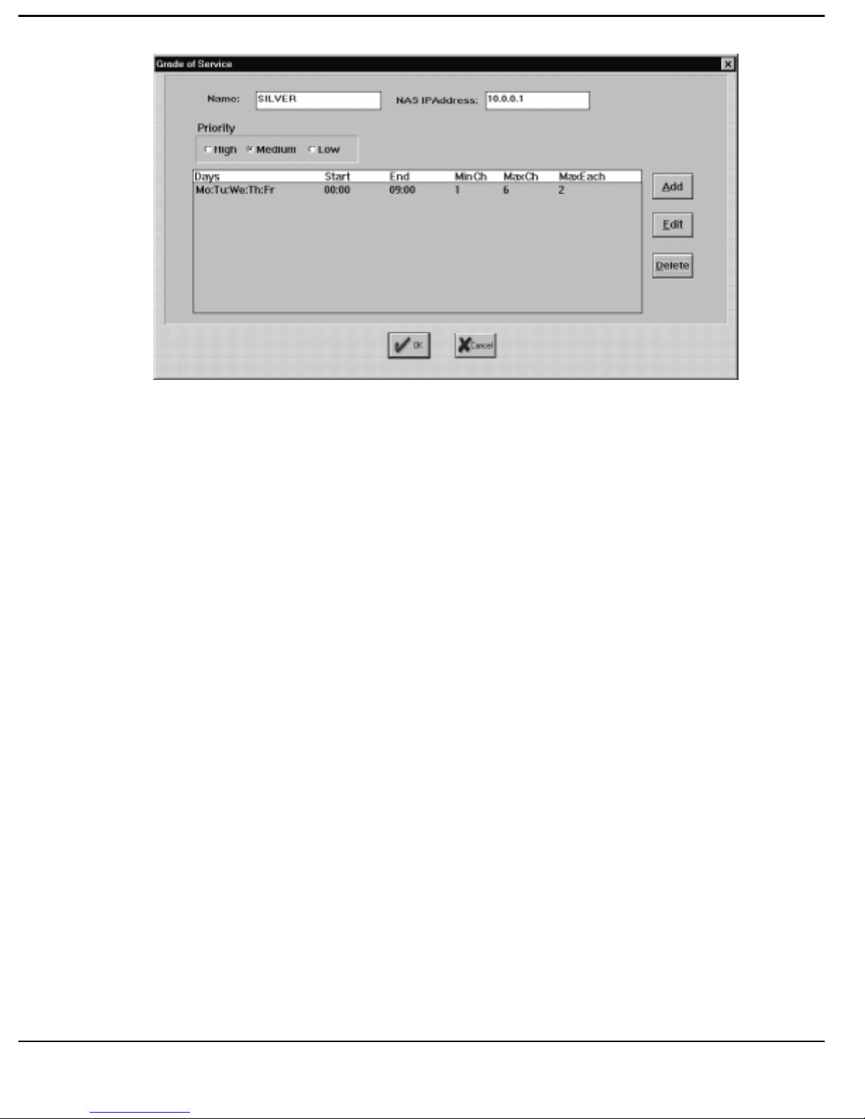
4. To allocate a new Grade of Service Name enter a meaningful name in the
“Name:” box. In this instance enter the Name SILVER.
5. Select the Priority of the new Grade of Service by [clicking] the
appropriate box - High, Medium or Low can be selected. Select
“Medium”.
6. Enter the IP Address of the associated NAS Router as applicable. For this
example enter 10.0.0.1.
The provisioning of any NAS System resource is regulated by the Priority
parameter set in the Account Users Grade of Service profile.
7. To add a Timeband to the new Grade of Service profile [click] the “Add”
Button.
If no Timebands are configured for a Grade of Service all connection requests
will rejected when the particular Grade of Service is in operation.
8. Set the Start Time by [double clicking] the “Start Time” Box and entering
the appropriate time (in 24 hour clock format). Enter a Start Time of
00:00.
9. Set the End Time by [double clicking] the “End Time” Box and entering
the appropriate time (again in 24 hour clock format). Enter an End Time
of 09:00.
Do not attempt to wrap a Timeband around Midnight, i.e. the End Time must
be greater than the Start Time.
10. Set the maximum number of channels allowed by all Account Users
during this Timeband (in the selected Grade of Service profile) by [double
clicking] the “MaxChannels” Box and entering the appropriate number of
channels. Enter a value of 6 in the MaxChannels Box.
3-11
Page 78

T
UTORIAL
11. Set the minimum number of channels allowed by all Account Users during
this Timeband (in the selected Grade of Service profile) by [double
clicking] the “MinChannels” Box and entering the appropriate number of
channels. Enter a value of 1 in the MinChannels Box.
The number of channels reserved on the NAS Router, for the selected Grade
of Service during this Timeband, is equal to the MinChannels value entered.
12. Set the maximum number of channels allowed by a single Account User
during this Timeband (in the selected Grade of Service profile) by [double
clicking] the “Max. per Account” Box and entering the appropriate
number of channels. Enter a value of 2 in the Max. per Account Box..
13. To select which day(s) in the week you want this Timeband to be active
[click] the appropriate box(es) under in the “Days of the Week” Box. For
this example select Monday (M), Tuesday (T), Wednesday (W), Thursday
(Th) and Friday (F).
14. [Click] the OK Button to return you to the “Grade of Service” window
when you have configured the appropriate options and Timebands for this
Grade of Service.
Once you have configured the Timeband information and submitted the
changes (by [clicking] the “OK” Button) the “Grade of Service” window
should be as shown at the top of the next page
3-12
Page 79
T
UTORIAL
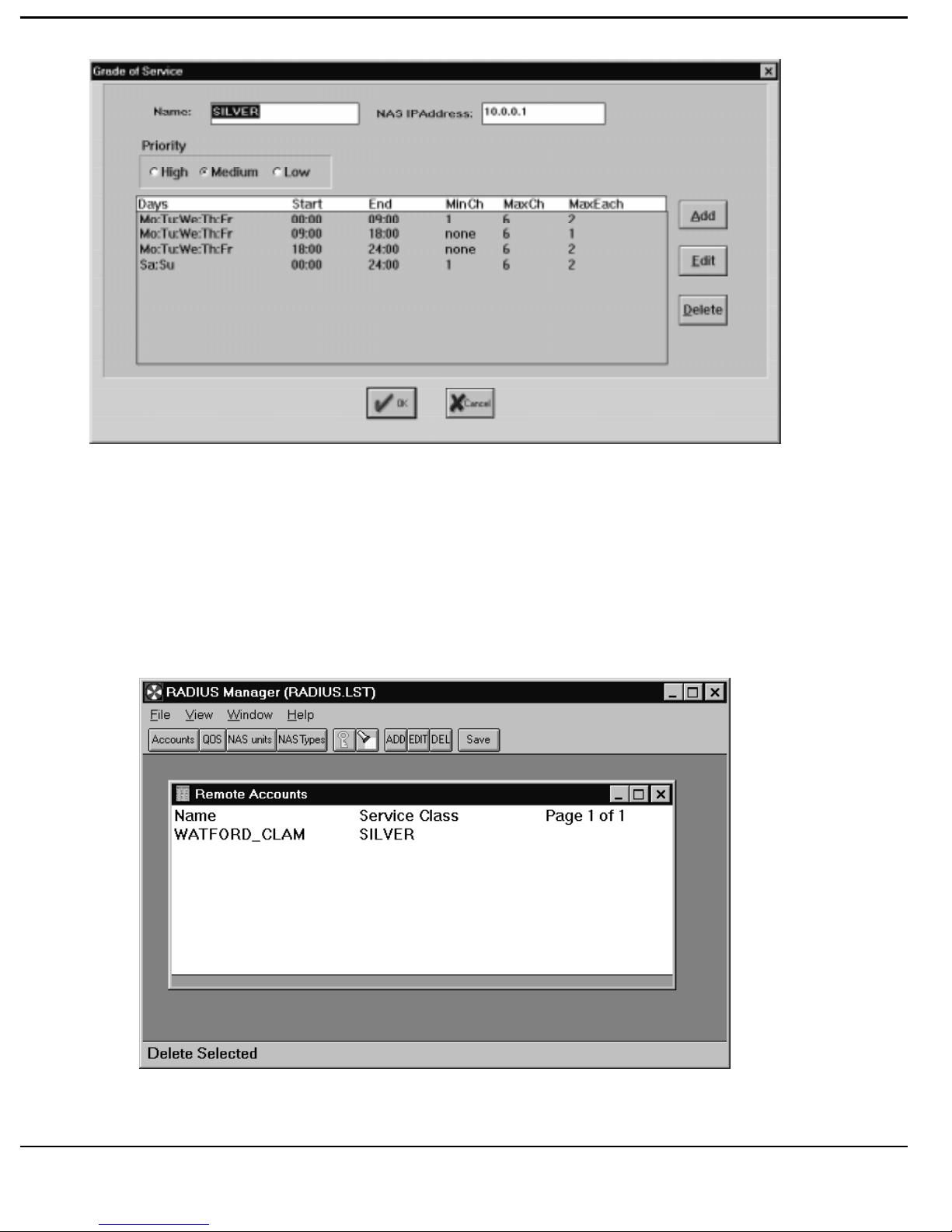
For this tutorial we will assign multiple Timebands to the SILVER Grade of
Service. To do this repeat sections 7) to 14) above each time an additional
Timeband is to be added to the Grade of service. The additional Timeband
information to be added is as follows :-
Start Time 09:00 Start Time 18:00 Start Time
00:00
End Time 18:00 End time 24:00 End Time
24:00
MaxChans 6 MaxChans 6 MaxChans 6
MinChans 0 MinChans 0 MinChans 1
Max. per Acc 1 Max. per Acc 2 Max. per Acc 2
Days MTWThF Days MTWThF Days SaSu
Once you have configured all the Timebands for the selected Grade of the
“Grade of Service” window should be as shown at the top of the next page :
3-13
Page 80
T
UTORIAL
15. Close the “Grade of Service” window by [clicking] the OK Button.
Once you have completed the Grade of Service information submit the
changes (by [clicking] the OK Button). The “Quality of Service” window
should be as shown below.
3-14
Page 81

T
UTORIAL
16. [Click] the Save Button to save all changes made to the Quality of Service
profiles.
17. Close the “Quality of Service” window by [clicking] the Close Button.
The “RADIUS Manager (RADIUS.LST)” window should now be
displayed.
4. Configuring the Accounts Option
1. If the RADIUS Manager Window is not already displayed on the screen
[click] the RADIUS Manager Button on the Task Bar.
2. [Click] the Accounts Button on the RADIUS Manager Toolbar. The
“Remote Accounts” window should appear.
Steps 3) to 54) below add a User Account for the remote LAN at Watford.
Steps 54) to 92) add a User Account for the roving PC user.
3. [Click] the ADD Button to add a new Account profile to the list, or select
an existing Account and [click] the EDIT Button to edit the configuration
of the Account Name selected.
4. To allocate a new Account Name enter a meaningful name in the “Name:”
box. In this instance enter the Name WATFORD_CLAM.
The NAS unit “Name” entered here must correspond exactly with the
associated remote Router’s Name [as configured in the Router’s System
Parameters Form (obtained by typing CO SY<CR> on the command line).
5. Select the “Inactivity” Box. Enter a value of 1200 (seconds). This sets
the session inactivity timeout to 20 mins.
Once there is no activity on the line to the remote User for the period specified
in the Inactivity timeout the RADIUS Server removes all routing and path
information from the NAS Router. If the remote User dials in again after the
3-15
Page 82

T
UTORIAL
Inactivity timeout period, and he has not exceeded his Usage limits, he will
have to go through the RADIUS Authentication process again.
6. [Click] the down-arrow on the right hand side of the Authentication Box.
The options revealed are UserPassword, CHAPPassword or
NoAuthentication. Select “UserPassword”.
The Authentication option UserPassword is normally used on Nautica Paths,
i.e. connections between Nautica Routers (on the Nautica Router this is called
a SecureKey and is found on the Configure Paths [CO PA] form), or on PPP
Paths if PAP Password Authentication is required. CHAPPassword is used on
PPP Paths when CHAP Authentication is required. If no Authentication is
required before the remote Account User gets access to the network the
NoAuthentication option should be used.
7. If the Authentication parameter is set to CHAPPassword or UserPassword
then the appropriate password must be entered in the Password Box. In
this instance enter 123 in the Password Box.
Do not use leading 0’s (zero’s) when entering a value into the Account
Password Box when using Nautica keys or numbers for PAP passwords. The
value entered in the Account Password Box must match the Outgoing PAP
Password, CHAP Secret or SecureKey used by the remote User exactly.
8. [Click] the down-arrow on the right hand side of the Address Assignment
Box. The options revealed are DontCare, NASSelects and Specific.
Select “DontCare”.
9. To enter a Specific IP Address for the remote Account User [click] the
Address Box and enter the required IP Address. In this instance leave the
Address Box Blank.
An IP Address should only be entered in the Address Box if “Specific” was
selected as the Address Assignment option.
10. [Click] the down-arrow on the right hand side of the CLI Box. The
options revealed are Ignored, ExactMatch and PartialMatch. Select
“ExactMatch”.
3-16
Page 83

T
UTORIAL
In this tutorial example it is assumed that ISDN line between the HQ and the
Remote Clam at Watford has the CLI option enabled at both ends.
11. Enter the CLI assigned to the remote end of this Account User’s ISDN
line. In this case the CLI is 01923123456.
12. [Click] the down-arrow on the right hand side of the Path Type Box. The
options revealed are PPP, Nautica and Undistinguished. Select Nautica
for this Account User (as it is a Nautica CLAM Router at the other end of
the ISDN line).
13. [Click] the Edit Button to the right of the Path Type Box. This will reveal
the “Multi-link Nautica Path” window.
14. If compression is required on the link between the NAS Router and the
remote Account User [click] the Compression Option Box. In this
instance select Compression.
15. [Click] the Bridge Unrouted Data option Box is you wish to allow
bridging on the line between the NAS Router and the remote Account
User. Do not select this option for this example.
16. Select the Max. Multi-link ports Box and enter the maximum number of
ISDN B-Channels that this Account User is allowed to use while
connecting to the NAS Router. Enter 2 in the Max. Multi-link ports Box.
The Max. Multi-link value entered is the maximum number of channels that
the NAS Router will allow to be bundled together for this remote Account
user. Please note however that the value entered in the Max. Multi-link ports
Box may be overridden by the number of channels assigned to the Max per
Account parameter in the Grade of Service profile that is in effect, if that
number is lower.
17. Next set the Outgoing Call Parameters. For this tutorial example set the
Demand Threshold to 50 (%), the Idle Threshold to 10 (%) and the
Threshold Period to 10 seconds.
The “Multi-link Nautica Path” window should now be exactly the same as that
shown at the top of the next page.
3-17
Page 84
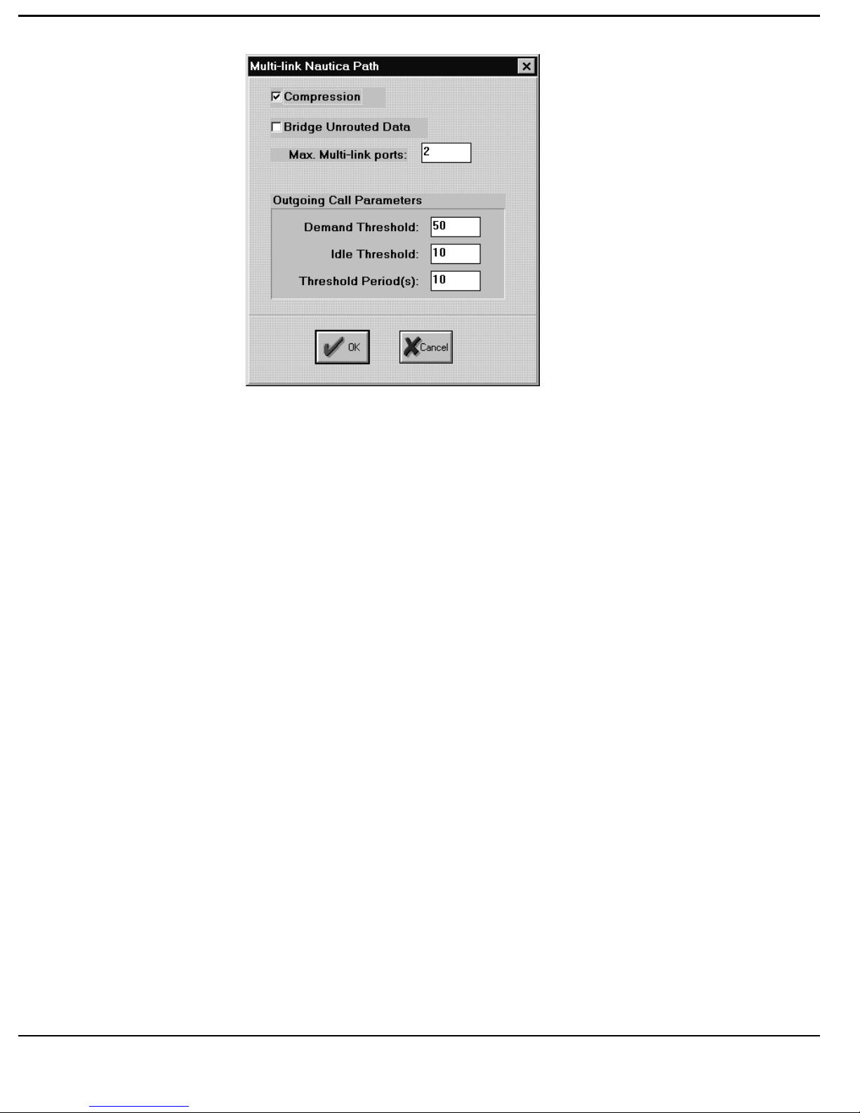
T
UTORIAL
18. Close the “Multi-link Nautica Path” window by [clicking] the OK Button.
The “Account Information” window should now be displayed.
19. [Click] the down-arrow on the right hand side of the IP Networking Box.
The options revealed are Enabled and Disabled. Select “Enabled”.
20. [Click] the Edit Button to the right of the IP Networking Box. This will
reveal “IPPath” window.
21. Select a value for RIP Operation on this Account User’s Path by [clicking]
the appropriate circle. In this instance select “Disable”. We will use static
IP routes on this Path.
22. Select a value for the RIP Type to be used on this Account User’s Path by
[clicking] the appropriate circle. In this instance select “RIP1Compatible
Please note that a RIP Type has to be selected even if the RIP Operation
parameter is set to Disable.
23. To add a Static IP Route which is associated with the Account Users Path
[click] the Add Button to the right of the IP Static Routes Table. This will
reveal the “Remote IP Subnet” window. [Click] the IP Static Routes Add
Button.
3-18
Page 85

T
UTORIAL
24. To enter a Static IP Route [double click] the IP Address/Mask Box and
enter the required IP address for the Static Route. In this instance enter
192.168.0.1/24.
25. [Click] the OK Button to submit the Static IP Route. The “IPPath”
window should now be displayed.
26. To add an IP Filter which is associated with the Account Users Path
[click] the Add Button to the right of the IP Filters Box. This will reveal
the “IP Address Filter” window. [Click] the IP Filters Add Button.
27. To enter an IP Address Filter firstly [double click] the IP Address1/Mask
Box and enter the required IP address of one of filter pair then [double
click] the IP Address2/Mask Box and enter the required IP address of the
other IP address of the filter pair. In this instance enter 192.168.0.0/24 for
IP Address1/Mask and 10.0.0.2/32 for IP Address2/Mask.
Note in the above example we are only allowing those packets coming from
the UNIX Host, 10.0.0.2, to Network 192.168.0.0/24 to create outgoing calls
on the ISDN line to the remote office.
The IP Filters work on a “Forward on Match” principle. Anything that
doesn’t match the Address’ configured in the IP Filters Table is discarded.
Source and Destination IP addresses on all packets entering the NAS Router
(on any port) destined for the remote Account User are checked for a match
before forwarding. For more information on IP Filtering refer to the Marlin
Router Reference Manual.
28. [Click] the OK Button to submit the IP Filter pair. The “IPPath” window
should now be displayed.
The “IPPath” window should now be exactly the same as that shown at the top
of the next page.
3-19
Page 86
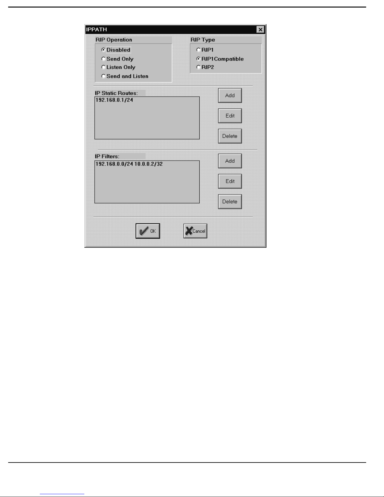
T
UTORIAL
29. Close the “IPPath” window by [clicking] the OK Button. The “Account
Information” window should now be displayed.
30. [Click] the down-arrow on the right hand side of the IPX Networking
Box. The options revealed are Enabled and Disabled. Select “Enabled”.
31. [Click] the Edit Button to the right of the IPX Networking Box. This will
reveal “IPXPath” window.
32. To add a Static IPX Route which is associated with the Account Users
Path [click] the Add Button to the right of the IPX Static Routes Table.
This will reveal the “Remote IPX Network” window. [Click] the IPX
Static Routes Add Button.
33. To enter a Static IPX Route [double click] the IPX Network Box and enter
the required IPX network address for the Static IPX Route. In this
instance enter 00DADD1E.
3-20
Page 87

T
UTORIAL
34. [Click] the OK Button to submit the Static IPX Route. The “IPXPath”
window should now be displayed.
35. To add an IPX Filter which is associated with the Account Users Path
[click] the Add Button to the right of the IPX Filters Box. This will reveal
the “IPX Net Filter” window. [Click] the IPX Filters Add Button.
36. To enter an IPX Network Filter firstly [double click] the IPX Net1 Box
and enter the required IPX network address of one of filter pair then
[double click] the IPX Net2 Box and enter the required IPX network
address of the other network of the filter pair. In this instance enter
00DADD1E for IPX Net1 and 00FE0691 for IPX Net2.
Note in the above example we are only allowing outgoing calls to be made for
data which is being sent from Network 00FE0691 to 00DADD1E.
The IPX Filters work on a “Forward on Match” principle also. Anything that
doesn’t match the Address’ configured in the IPX Filters Table is discarded.
Source and Destination IPX Network addresses on all packets entering the
NAS Router (on any port) destined for the remote Account User are checked
for a match before forwarding. For more information on IPX Filtering refer to
the Marlin Router Reference Manual.
37. [Click] the OK Button to submit the IPX Filter pair. The “IPXPath”
window should now be displayed.
38. To add an IPX SAP Filter which is associated with the Account Users
Path [click] the Add Button to the right of the IPX SAP Filters Box. This
will reveal the “IPX SA Filter” window. [Click] the IPX SAP Filters Add
Button.
39. To enter an IPX SAP Filter [click] the Server Name Box and enter the
required IPX SAP address. In this instance enter Accounts*.
Note in the above example by using the wildcard variable “*”we are
effectively allowing all SAPs starting with the letters “Accounts” to be passed
to the remote Account User, i.e. this is effectively restricting the outgoing IPX
SAP broadcast to those SAP starting with “Accounts”.
3-21
Page 88

T
UTORIAL
The IPX SAP Filter works on a “Forward on Match” principle also. Anything
that doesn’t match the IPX SAPs configured in the IPX SAP Filter table
discarded before being passed onto the remote Account User. For more
information on IPX SAP Filtering refer to the Marlin Router Reference
Manual.
40. [Click] the OK Button to submit the IPX SAP Filter information. The
“IPXPath” window should now be displayed.
41. Select a value for RIP/SAP Operation on this Account User’s Path by
[clicking] the appropriate circle. In this instance select “Send Only”. This
will send SAP broadcasts to the remote Account Users Router but will not
listen to any SAP broadcasts sent out by the remote Account User’s
Router.
3-22
Page 89
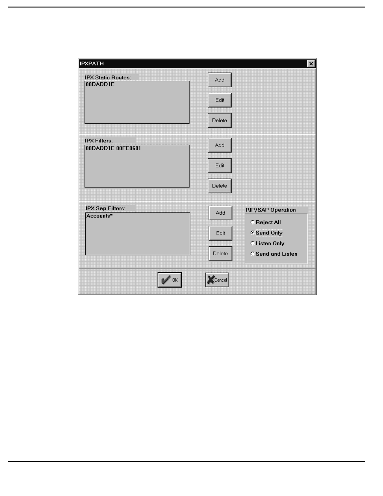
T
UTORIAL
The “IPXPath” window should now be exactly the same as that shown below.
42. Close the “IPXPath” window by [clicking] the OK Button. The “Account
Information” window should now be displayed.
43. [Click] the down-arrow on the right hand side of the Outgoing Calls Box.
The options revealed are Allowed and Disallowed. Select “Allowed”.
44. To enter the Telephone number to use to dial the remote Account User if
the Outgoing Call option is set to Allowed [click] the Tel Box and enter
the appropriate ISDN number of the remote Account User. For this
example enter 01923123456 in the Tel Box.
45. [Click] the down-arrow on the right hand side of the Service Box. The
options revealed are a list of all configured Quality of Service Profiles and
one called “Default”. For this example select “SILVER”.
3-23
Page 90
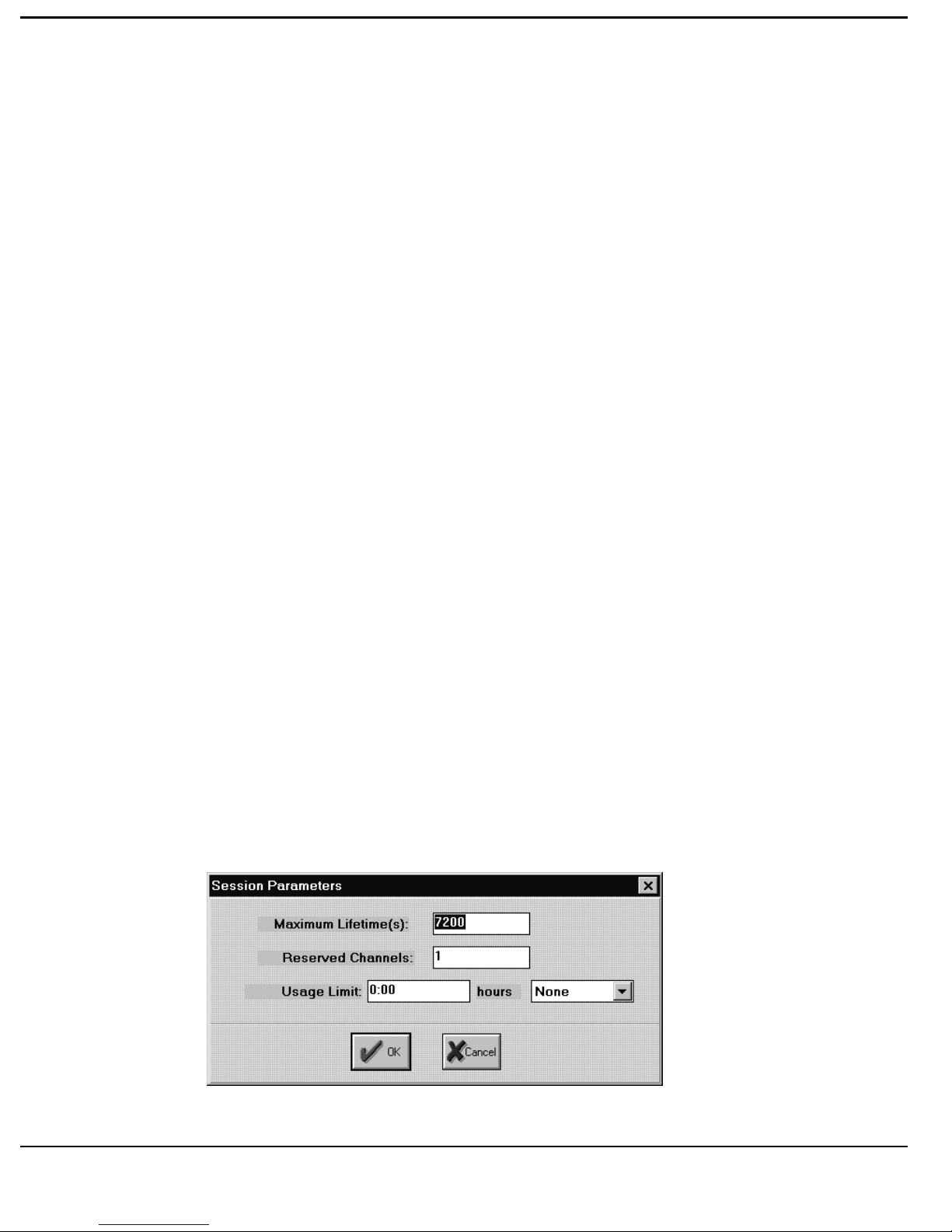
T
UTORIAL
46. [Click] the Edit Button to the right of the Service Box. This will reveal
“Session Parameters” window.
47. If you wish to alter the default Maximum (Session) Lifetime setting of
7200 seconds (2 hours) then [click] the Maximum Lifetime Box and enter
the appropriate value. In this instance leave the value at its default setting
of 7200.
48. If you wish to alter the default Reserved Channels (for the Session) setting
of 0 then [click] the Reserved Channels Box and enter the appropriate
value. In this instance set the value to 1.
The Reserved Channels option in the Session Parameters window will
automatically reserved the number of channels entered in the Reserved
Channels Box in the NAS Router once the session has started, unless there are
not enough unused channels to fulfil this requirement, in this instance as many
channels as possible will be reserved. A reservation of 1 implies that one
channel will be reserved for the Account User if the line drops (due to
inactivity) and he will automatically get connected next time he brings the line
up i.e. he will always get a connection and should never get Busy on the line.
49. If you wish to alter the default Usage Limit (for the Session) setting of
0:00 then [click] the Usage Limit Box and enter the appropriate value.
[Click] the down-arrow to the right of the hours Box to select from none,
hours per day, hours per week or hours per month. In this instance leave
the Usage Limit value and the hours value at their default settings of 0:00
and none respectively.
The “Session Parameters” window should now be exactly the same as that
shown below.
3-24
Page 91

T
UTORIAL
50. [Click] the OK Button to submit the Session Parameters. The “Account
Information” window should now be displayed.
51. [Click] the down-arrow on the right hand side of the Accounting Box.
The options revealed are Standard or Periodic. For this example select
“Standard”.
Periodic is used when the remote Account User is connected to the NAS
Router via a Leased Line. In this instance accounting of leased line
services on a periodic basis should be performed, rather than on a call by
call basis.
52. If the Accounting option is set to “Periodic” a value must be entered into
the Intervals(s) Box. This is done by [clicking] the Intervals(s) Box and
entering the required accounting reporting period in seconds. In this
instance leave the Intervals(s) Box blank as we have already selected
“Standard” Accounting.
3-25
Page 92
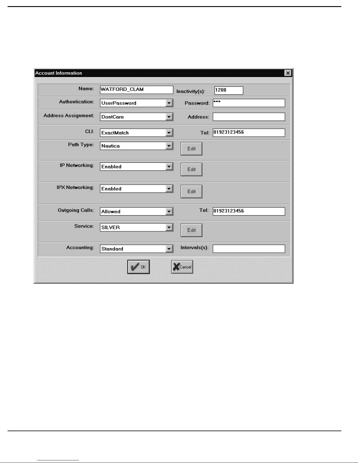
T
UTORIAL
The “Account Information” window should now be exactly the same as that
shown at the top of the next page.
3-26
Page 93
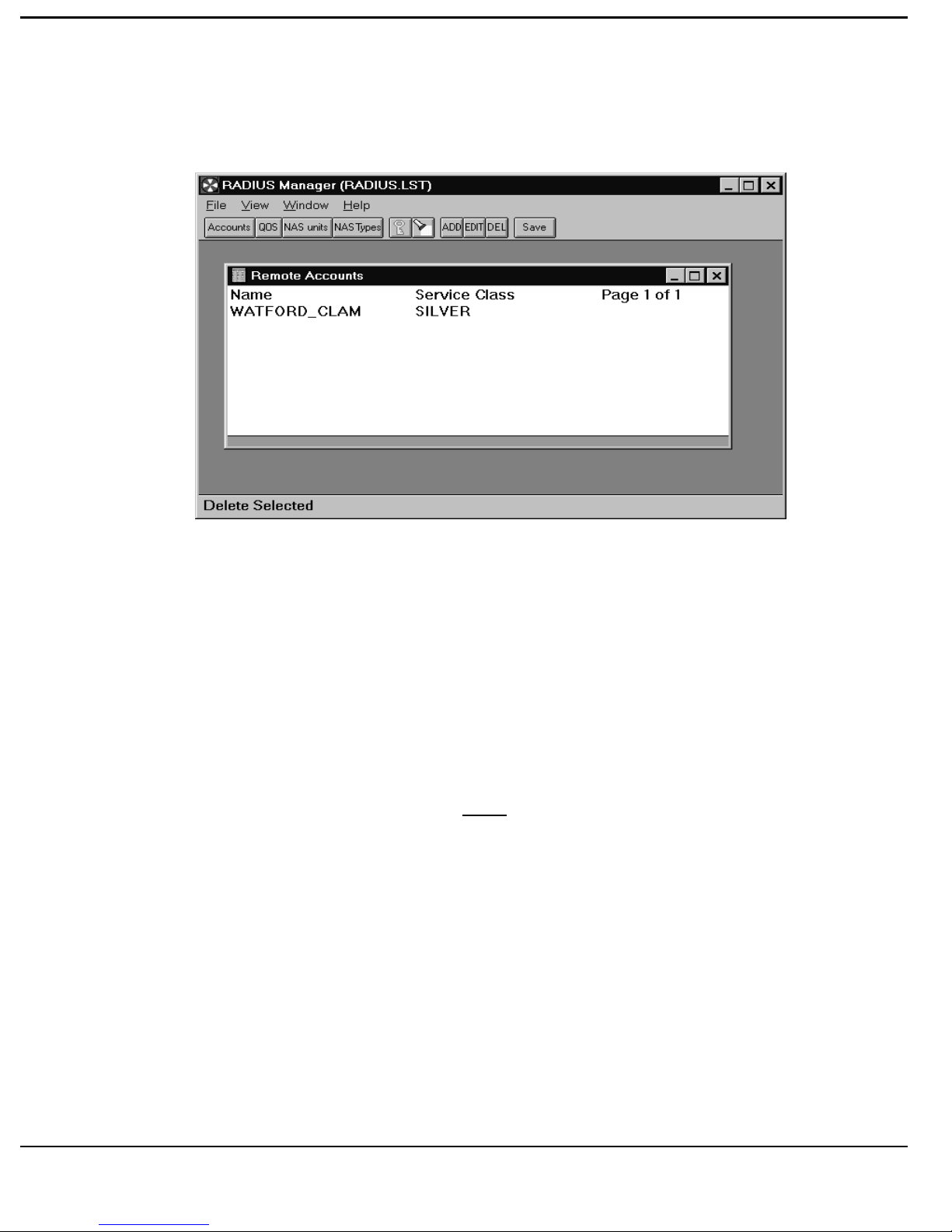
T
UTORIAL
53. [Click] the OK Button to submit the Account Information. The “Remote
Accounts” window should now be displayed as shown below.
54. [Click] the SAVE Button to save all changes made to the Remote Account
profiles.
55. [Click] the ADD Button to add a new Account profile to the list, or select
an existing Account and [click] the EDIT Button to edit the configuration
of the Account Name selected.
56. To allocate a new Account Name enter a meaningful name in the “Name:”
box. In this instance enter the Name PPP_PC.
The NAS unit “Name” entered here must correspond exactly with Name
associated with the remote PC, i.e. the unit name or unit Id allocated to the PC
when configuring the PC’s PPP stack.
57. Select the “Inactivity” Box. Enter a value of 600 (seconds). This sets the
session inactivity timeout to 10 mins.
58. [Click] the down-arrow on the right hand side of the Authentication Box.
The options revealed are UserPassword, CHAPPassword or
NoAuthentication. Select “CHAPPassword”.
3-27
Page 94

T
UTORIAL
59. Select the Password Box by [clicking] it. Enter CHAPPC in the Password
Box.
60. [Click] the down-arrow on the right hand side of the Address Assignment
Box. The options revealed are DontCare, NASSelects and Specific.
Select “NASSelects”.
61. Leave the Address Box blank.
62. [Click] the down-arrow on the right hand side of the CLI Box. The
options revealed are Ignored, ExactMatch and PartialMatch. Select
“Ignored”.
In this tutorial example it is assumed that number of the line used by the
roving PC User will continually change. Therefore there is no point in
checking the CLI of the remote end of the line each time the roving Account
User dials in.
63. Leave the CLI (Tel) Box Blank.
64. [Click] the down-arrow on the right hand side of the Path Type Box. The
options revealed are PPP, Nautica and Undistinguished. Select PPP for
this Account User (as it is a PC using an Integral TA and a PPP stack).
65. [Click] the Edit Button to the right of the Path Type Box. This will reveal
the “Multi-link PPP Path” window.
66. Leave the Bridge Unrouted Data Box blank
67. The Bridge Unrouted Data should never be selected on PPP Paths, as there
is currently no support for BCP (Bridging) on PPP Paths.
68. Select the Max. Multi-link ports Box and enter the maximum number of
ISDN B-Channels that this Account User is allowed to use while
connecting to the NAS Router. Enter 1 in the Max. Multi-link ports Box.
69. Next set the Outgoing Call Parameters. For this tutorial example leave the
Demand Threshold at 0 (%), the Idle Threshold at 0 (%) and the Threshold
Period at 10 seconds, i.e. their Default values.
3-28
Page 95
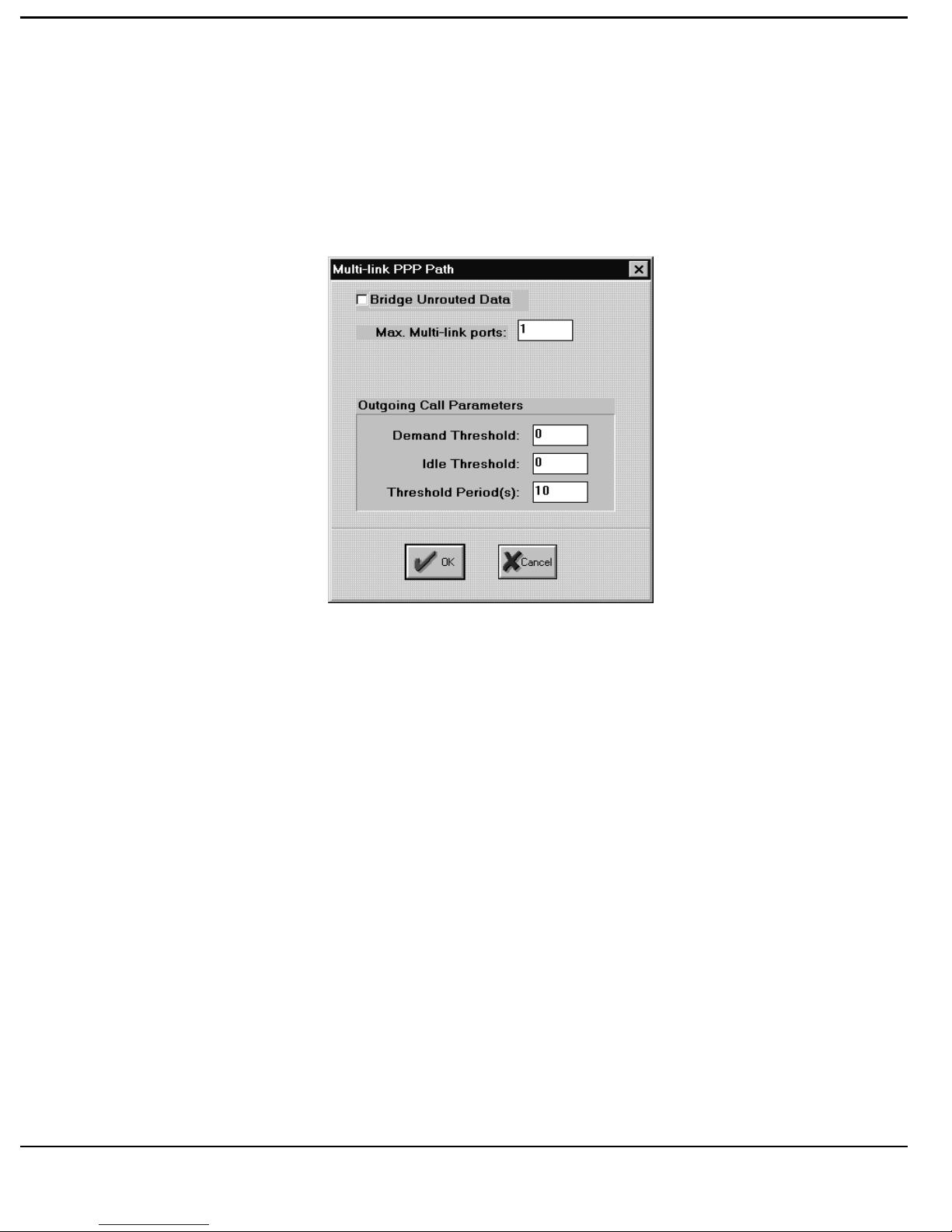
T
UTORIAL
If the roving PC User has the ability to use Multlink PPP (RFC 1717) then the
Ma. Multi_link ports option can be set to 2. If additional bandwidth on
demand is required the Outgoing Call Parameters must be set accordingly.
The “Multi-link PPP Path” window should now be exactly the same as that
shown below.
69. Close the “Multi-link PPP Path” window by [clicking] the OK Button.
The “Account Information” window should now be displayed.
70. [Click] the down-arrow on the right hand side of the IP Networking Box.
The options revealed are Enabled and Disabled. Select “Enabled”.
71. [Click] the Edit Button to the right of the IP Networking Box. This will
reveal “IPPath” window.
72. Select a value for RIP Operation on this Account User’s Path by [clicking]
the appropriate circle. In this instance select “Disable”.
As the roving PC User is effectively part of the main HQ backbone LAN and
he is not a Router there is no need to send IP RIPs down to him. If he want’s
to route to anywhere other than the main HQ LAN he should configure a
Gateway on his PC.
73. Select a value for the RIP Type to be used on this Account User’s Path by
[clicking] the appropriate circle. In this instance select “RIP1Compatible
3-29
Page 96

T
UTORIAL
74. Leave the Static IP Route table Blank.
No Static Routes are as the roving PC User is part of the main HQ IP
Network.
75. To add an IP Filter which is associated with the roving PC Account Users
Path [click] the Add Button to the right of the IP Filters Box. This will
reveal the “IP Address Filter” window. [Click] the IP Filters Add Button.
76. To enter an IP Address Filter firstly [double click] the IP Address1/Mask
Box and enter the required IP address of one of filter pair then [double
click] the IP Address2/Mask Box and enter the required IP address of the
other IP address of the filter pair. In this instance enter
255.255.255.254/32 for IP Address1/Mask and 10.0.0.2/32 for IP
Address2/Mask.
Note in the above example we are allowing any user which has been assigned
an IP Address by the NAS Router (done by using the value 255.255.255.254)
to only access the UNIX Host at address 10.0.0.2.
77. [Click] the OK Button to submit the IP Filter pair. The “IPPath” window
should now be displayed.
The “IPPath” window should now be exactly the same as that shown below.
3-30
Page 97
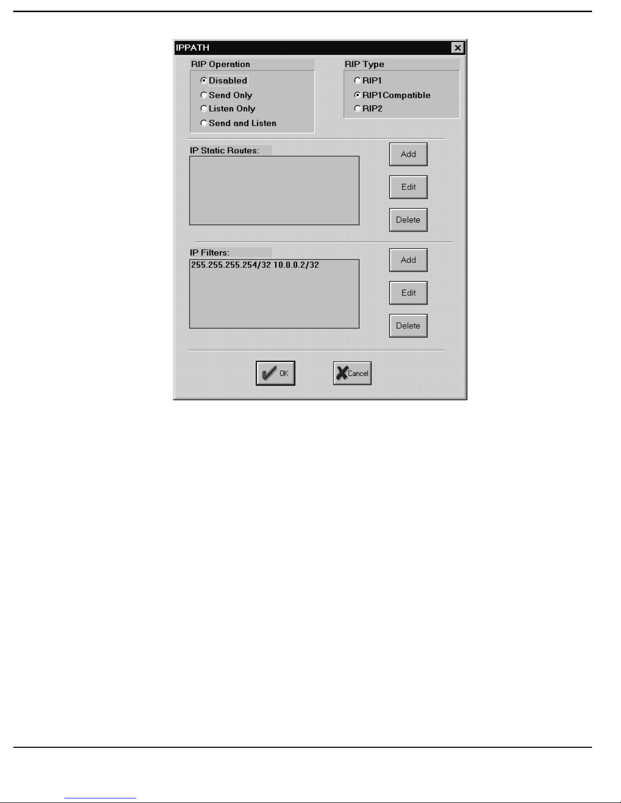
T
UTORIAL
78. Close the “IPPath” window by [clicking] the OK Button. The “Account
Information” window should now be displayed.
79. [Click] the down-arrow on the right hand side of the IPX Networking
Box. The options revealed are Enabled and Disabled. Select “Disabled”.
80. [Click] the down-arrow on the right hand side of the Outgoing Calls Box.
The options revealed are Allowed and Disallowed. Select “Disallowed”.
81. Leave the (Outgoing Call) Tel Box Blank.
[Click] the down-arrow on the right hand side of the Service Box. The
options revealed are a list of all configured Quality of Service Profiles and
one called “Default”. For this example again select “SILVER”.
Note that we have used the same Quality of Service profile for both the roving
PC User and the remote LAN for simplicity in the tutorial. This need not
3-31
Page 98

T
UTORIAL
necessarily be the case. Any Account User can use any predefined Quality of
Service profile.
82. [Click] the Edit Button to the right of the Service Box. This will reveal
“Session Parameters” window.
83. Leave the Maximum (Session) Lifetime value at its default setting of 7200
seconds.
84. Leave the Reserved Channels (for the Session) setting at 0.
85. Leave the Usage Limit value and the hours value at their default settings
of 0:00 and none respectively.
3-32
Page 99
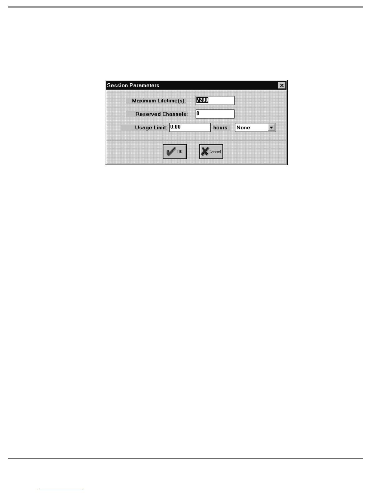
T
UTORIAL
The “Session Parameters” window should now be exactly the same as that
shown below.
87. [Click] the OK Button to submit the Session Parameters. The “Account
Information” window should now be displayed.
88. Set the Accounting option to “Standard”.
89. Leave the Intervals(s) Box blank.
3-33
Page 100
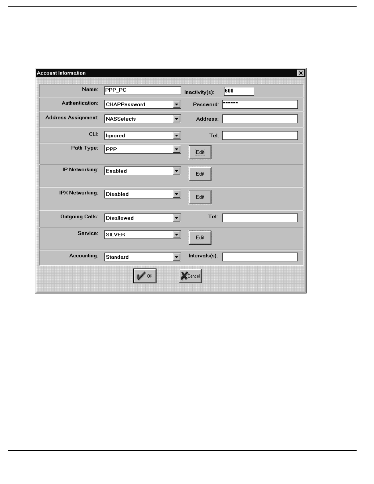
T
UTORIAL
The “Account Information” window should now be exactly the same as that
shown below.
90. [Click] the OK Button to submit the Account Information. The “Remote
Accounts” window should now be displayed as shown below.
91. [Click] the Save Button to save all changes made to the Remote Account
profiles.
92. [Click] the Close Button to submit the Remote Accounts information.
The “RADIUS Manager (RADIUS.LST)” window should now be
displayed.
3-34
 Loading...