

Page 1

Nautica Marlin
Bridge Reference
Guide
Part No. 302976-A Rev.00
May 1998
Page 2

4401 Great America Parkway 8 Federal Street
Santa Clara, CA 95054 Billerica, MA 01821
Copyright © 1998 Bay Networks, Inc.
All rights reserved. Printed in the USA. May 1998.
The information in this document is subject to change without notice. The statements,
configurations, technical data, and recommendations in this document are believed to be
accurate and reliable, but are presented without express or implied warranty. Users must
take full responsibility for their applications of any products specified in this document.
The information in this document is proprietary to Bay Networks, Inc.
The software described in this document is furnished under a license agreement and may
only be used in accordance with the terms of that license. A summary of the Software
License is included in this document.
Trademarks
Bay Networks is a registered trademarks and Nautica and the Bay Net works logo are
trademarks of Bay Networks, Inc.
Microsoft, MS, MS-DOS, Win32, Windows, and Windows NT are registered trademarks
of Microsoft Corporation.
All other trademarks and registered trademarks are the property of their respective owners.
Restricted Rights Legend
Use, duplication, or disclosu re by the United States Gov ernment is sub ject to restrictio ns as
set forth in subparagraph (c)(1)(ii) of the Rights in Technical Data and Computer Software
clause at DFARS 252.227-7013.
Notwithstanding any other license agreement that may pertain to, or accompany the
delivery of, this computer software, the rights of the United States Government regarding
its use, reproduction, and disclosure are as set forth in the Commercial Computer
Software-Restricted Rights clause at FAR 52.227-19.
Statement of Conditions
In the interest of improving internal design, operational function, and/or reliability, Bay
Networks, Inc. reserves the right to make changes to the products described in this
document without notice.
Bay Networks, Inc. does no t assume an y liabilit y t hat may oc c ur due to the use or
application of the product(s) or cir cuit layout(s) described herein.
Portions of the code in this sof twar e product are Copyright © 1988, Regent s of the
University of California. Al l rights reserved. Redistr ibution and use in source and binary
forms of such po rtions are permit ted, provided that the above copyright notice and this
paragraph are duplicated in all such forms and that any documentation, adve rtising
materials, and other materials related to such distribution and use acknowledge that such
portions of the software were developed by the University of California, Berkeley. The
ii 302976-A Rev.00
Page 3

name of the U niversity ma y not be used to endor se or promote produc t s d er ived from such
portions of the software witho ut speci fic prior written permission.
SUCH PORTIONS OF THE SOFTWARE ARE PROVIDED “AS IS” AND WITHOUT
ANY EXPRESS OR IMPLIED WARRANTIES, INCLUDING, WITHOUT
LIMITATION, THE IMPLIED WARRANTIES OF MERCHANTABILITY AND
FITNESS FOR A PAR TICULAR PURPOSE.
In addition, the program and information contained herein are licensed only pursuant to a
license agreement that contains restrictions on use and disclosure (that may incorporate by
reference ce rtain limitations and notices imposed by third parties).
Bay Netw orks, Inc. Software License Agreement
NOTICE: Please carefully read this license agreement before copying or using the
accompanying software or installing the hardware unit with pre-enabled software (each of
which is referred to as “Software” in this Agreement). BY COPYING OR USING THE
SOFTWARE, YOU ACCEPT ALL OF THE TERMS AND CONDITIONS OF THIS
LICENSE AGREEMENT. THE TERMS EXPRESSED IN THIS AGREEMENT ARE
THE ONLY TERMS UNDER WHICH BAY NETWORKS WILL PERMIT YOU TO
USE THE SOFTWARE. If you do not accept these terms and conditions, return the
product, unused and in the original shipping container, within 30 days of purchase to
obtain a credit for the full purchase price .
1. License Grant. Bay Networks, Inc. (“Bay Networks”) grants the end user of the
Software (“Licensee”) a personal, nonexclusive, nontransferable license: a) to use the
Software either on a single computer or, if applicable, on a single authorized device
identified by host ID, for which it was originally acquired; b) to copy the Software solely
for backup purposes in su pport of authorized use of the Software; and c) to use and copy
the associated user manual solely in support of authorized use of the Software by Licensee.
This license applies to the Software only and does not extend to Bay Networks Agent
software or other Bay Networks software products. Bay Networks Agent software or other
Bay Netwo rks so ftw ar e pro duc ts a re licen sed f or u se unde r t he te rms of the a ppli cab le Ba y
Networks, Inc. Software License Agreement th at accompanies such software and upon
payment by the end user of the applicabl e license fees for such software.
2. Restrict i ons on us e ; r e se r vation of rights. The Software and user manuals are
protected under copyright laws. Bay Networks and/or its licensors retain all title and
ownership in both the Software and us er manuals, includ ing any revisions made by Bay
Networks or its licensors. The copyright notice must be reproduced and included with any
copy of any portion of the Software or user manuals. Licensee may not modify, translate,
decompile, disassemble, use for any competitive analysis, reverse engineer, distribute, or
create derivative works from the Software or user manuals or any copy, in whole or in part.
Except as expressly provided in this Agreement, Licensee may no t copy or transfer the
Software or user manuals, in whole or in part. The Software and user manuals embody Bay
Networks’ and its licensors’ confidential and proprietary intellectual property. Licensee
shall not subl icense, assign, or otherwise disclose to any third pa rt y the Software, or any
information about the oper atio n, de sig n, perfo rm anc e, or implem e ntatio n of the Softwa re
and user manuals that is confidential to Bay Networks and its licensors; however , Licensee
may grant permission to its consultants, subcontractors, and agents to use the Software at
302976-A Rev.00 iii
Page 4

Nautica Marlin Bridge Reference Guide
Licensee’s facility, provided they have agreed to use the Software only in accordance with
the terms of this license.
3. Limited warranty. Bay Networks warrants each item of Software, as delivered by Bay
Networks and properly installe d and operated on Bay Networks hardware or other
equipment it is originally licensed for, to function substantially as described in its
accompanying user manual during it s warranty period, which begins on the date Software
is first shipped to Licensee. If any item of Software fails to so function during its warranty
period, as the so le re med y Bay Net wo r ks will a t it s d iscretio n p ro v id e a su ita ble fix, patch,
or workaround for the problem that may be included in a future Software release. Bay
Networks further warrants to Licensee that the media on which the Software is provided
will be free from defects in ma terials and w orkmanship un der normal us e for a period of 9 0
days from the date Software is first shipped to Licensee. Bay Networks will replace
defective media at no charge if it i s returned to Bay Networks during the warra nty period
along with proof of the date of shipment. This warranty does not apply if the media has
been damaged as a result of accident, misuse, or abuse. The Licensee assumes all
responsibility for selection of the Software to achieve Licensee’s intended results and for
the installation, use, and results obtained from the Software. Bay Networks does not
warrant a) that the functions contained in the software will meet the Licensee’s
requirements, b) that the Software will operate in the hardware or software combinations
that the Licensee may select, c) that the operation of the Software will be uninterrupted or
error free, or d) that all defects in the operation of the Software will be corrected. Bay
Networks is not obl igated to remedy any Software defect that cannot be reproduced with
the latest Software release. These warranties do not apply to the Software if it has been (i)
altered, except by Bay Networks or in accordance with its instructions; (ii) used in
conjunction with another vendor’s product, resulting in the defect; or (iii) damaged by
improper environment, abuse, misuse, accident, or negligence. THE FOREGOING
WARRANTIES AND LIMITATIONS ARE EXCLUSIVE REMEDIES AND ARE IN
LIEU OF ALL OTHER WARRANTIES EXPRESS OR IMPLIED, INCLUDING
WITHOUT LIMITATION ANY WARRANTY OF MERCHANTABILITY OR FITNESS
FOR A PARTICULAR PURPOSE. Licensee is responsible for the security of it s own data
and information and for maintaining adequate procedures apart from the Software to
reconstr uct lost or altered files, data, or programs.
4. Limitation of liability. IN NO EVENT WILL BAY NETWORKS OR ITS
LICENSORS BE LIABLE FOR ANY COST OF SUBSTITUTE PROCUREMENT;
SPECIAL, INDIRECT, INCIDENTAL, OR CONSEQUENTIAL DAMAGES; OR ANY
DAMAGES RESULTING FROM INACCURATE OR LOST DATA OR LOS S OF USE
OR PROFITS ARISING OUT OF OR IN CONNECTION WITH THE PERFORMANCE
OF THE SOFTWARE, EVEN IF BAY NETWORKS HAS BEEN ADVISED OF THE
POSSIBILITY OF SUCH DAMAGES. IN NO EVENT SHALL THE LIABILITY OF
BAY NETWORKS RELATING TO THE SOFTWARE OR THIS AGREEMENT
EXCEED THE PRICE PAID TO BAY NETWORKS FOR THE SOFTWARE LICENSE.
5. Government Licensees. This provision ap pli es to all Sof tware and documentation
acquired directly or indirectly by or on behalf of the United States Government. The
Software and documentation are commercial products, licensed on the open market at
market prices, and were developed entirely at private expense and without the us e of any
U.S. Government funds. The license to the U.S. Government is granted only with restricted
rights, an d use, duplic ation, or disclosure by the U.S. Government is subject to t he
iv 302976-A Rev.00
Page 5

restrictions set forth in subparagraph (c)(1) of the Commercial Computer
Software––Restricted Rights clause of FAR 52.227-19 and the limitations set out in this
license for civilian agencies, and subparagraph (c)(1)(ii) of the Rights in Technical Data
and Computer Software clause of DFARS 252.227-7013, for agencies of the Department
of Defense or their successors, whichever is applicable.
6. Use of Software in the European Community. This provision applies to all Software
acquired for use within the European Community. If Licensee uses the Software within a
country in the European Community, the Software Directive enacted by the Council of
European Communit ies Dire cti v e dated 14 Ma y, 1991, will apply to th e e xamina tion of the
Software to facili ta te inte ro pera bil ity. Licensee agrees to no tify Bay Ne tworks of any such
intended examination of the Software and may procure support and assistance from Bay
Networks.
7. Term and termination. This license is effective until terminated; however, all of the
restrictions with respect to Bay Networks’ copyright in the Software and user manuals will
cease being effective at the date of exp iration of the Bay Networks copyright; those
restrictions relating to use and disclosure of Bay Networks’ confidential information shall
continue in effect. Licensee may terminate this license at any time. The license will
automatically termin ate if Licens ee fails to comply with any of the terms and condi tions of
the license. Upon termination for any reason, Licensee will immediately destroy or return
to Bay Networks the Software, user manuals, and all copies. Bay Networks is not liable to
Licensee for damages in any form solely by reason of the termination of this license.
8. Export and Re-export. Licensee agrees not to export, directly or indirectly, the
Software or related technical data or information without first obtaining any required
export lic ense s or ot her go vernmental appro v al s. Without limiting th e fo re goin g, L icens ee,
on behalf of itself and its subsidiaries and affiliates, agrees that it will not, without first
obtaining all export licenses and approvals required by the U.S. Government: (i) export,
re-export, tr ansfer, or divert any such Software or technical data, or any direct product
thereof, to any country to which such exports or re-exports ar e restricted or embargoed
under United States export control laws and regulations, or to any national or resident of
such restricted or embargoed countries; or (ii) provide the Software or related technical
data or information to any milita ry end user or for any military end use, including the
design, development, or production of any chemical, nuclear, or biological weapons.
9. General. If any provision of this Agreement is held to be invalid or unenforceable by a
court of competent jurisdiction, the remainder of the provisions of this Agreement shall
remain in full force and effect. This Agreement will be governed by the laws of the state of
California.
Should you have any questions concerning this Agreement, contact Bay Networks, Inc. ,
4401 Great America Parkway, P.O. Box 58185, Santa Clara, California 95054-8185.
LICENSEE ACKNOWLEDGES THAT LICENSEE HAS READ THIS AGREEMENT,
UNDERSTANDS IT, AND AGREES TO BE BOUND BY ITS TERMS AND
CONDITIONS. LICENSEE FURTHER AGREES THAT THIS AGREEMENT IS THE
ENTIRE AND EXCLUSIVE AGREEMENT BETWEEN BAY NETWORKS AND
LICENSEE, WHICH SUPERSEDES ALL PRIOR ORAL AND WRITTEN
AGREEMENTS AND COMMUNICATIONS BETWEEN THE PARTIES PERTAINING
TO THE SUBJECT MATTER OF THIS AGREEMENT. NO DIFFERENT OR
ADDITIONAL TERMS WILL BE ENFORCEABLE AGAINST BAY NETWORKS
302976-A Rev.00 v
Page 6

Nautica Marlin Bridge Reference Guide
UNLESS BAY NETWORK S GIVES ITS EXPRESS WRITTEN CONSENT,
INCLUDING AN EXPRESS WAIVER OF THE TERMS OF THIS AGREEM ENT.
vi 302976-A Rev.00
Page 7

Contents
About This Guide
Before You Begin ........................................................................xix
Conventions ................................................................................ xx
Acronyms ........................ .............................................. ..............xxi
Bay Networks Technical Publications .......................................xxiii
Bay Networks Customer Service ..............................................xxiii
How to Get Help .......................................................................xxiv
Bay Networks Educational Services ..........................................xxv
Chapter 1
Understanding Bridging
High Performance Ethernet Bridge ............................................1-2
ISDN For Resilience ..................................................................1-2
ISDN Top-up Bandwidth On Demand ........................................1-3
ISDN Autocall Bandwidth On Demand ................................1-3
Protocol Routing And Spoofing ..................................................1-4
Simple Installation And Management ........................................1-4
Security .. ......................... .......................... .......................... .......1 -5
Additional Modules ....................................................................1-5
Optional Expansion Cards ..................................................1-5
Optional Single and Dual Integrated
BRI ISDN Terminal Adapters ...............................................1-6
Optional Primary Rate EURO-ISDN Interface (NET5/iCTR4) 1-6
Optional Primary Rate US Interface (National ISDN) ..........1-6
Optional Quad WAN Port Expansion Board ........................1-7
Optional 8 Port 10BASE-T Hub Expansion Board ..............1-7
302976-A Rev.00 vii
Page 8

Chapter 2
Bridging Network Designs
Pont-to-Point Bridge Pair Networks ...........................................2-2
Single Link ...........................................................................2-2
Installation .......... ............. ............. ............. ............. .......2-3
Parallel Links .......................................................................2-3
Installation .......... ............. ............. ............. ............. .......2-4
ISDN Backup .......................................................................2-5
ISDN Interconnect Only ......................................................2-7
Multiple Bridge Pairs Network ..................................................2-10
Installation .......... ............. ............. ............. ............. .....2-11
Brdige Triangulation Networks .................................................2-12
Simple Triangulation ..........................................................2-12
Multiple Triangulation ........................................................2-13
Resilient Links ........................................... ...... ....... ...... .....2-14
Fully Resilient Triangulation ...............................................2-15
Fully Resilient With ISDN Backup .....................................2-16
Cost Reduced ISDN Backup .............................................2-18
Multi-tiered Network .................................................................2-20
Autocalls For ISDN Only Lan Interconnect ..............................2-22
TCP/IP Autocalls ...............................................................2-23
Novell IPX Autocalls ..........................................................2-23
SCANET OSI Name Service Autocalls .............................2-24
Banyan Au tocalls ...............................................................2-25
Chapter 3
Manager Operation
Introduction ................................................................................ 3-2
Menus And Forms .....................................................................3-3
Fr ont Panel Operation ................................................................3-4
FRONT PANEL DISPLAY ....................................................3-4
MENU NAVIGATION VIA THE FRONT PANEL ...................3-4
Form Display and Editing Via the Front Panel .....................3-5
viii 302976-A Rev.00
Page 9

Saving Changes Via the Front Panel ..................................3-6
Interface Activity Bar Graph Operation ................................3-7
Manager Terminal Operation .....................................................3-7
Screen Description ..............................................................3-8
Title Line Region ....... ...... ....... ...... ....... ...... ....... ...... .......3-8
Central Menu and Form Region ...................................3-8
Menu Navigation Region ........................... ....... .............3-9
Command and Response Region .................................3-9
Menu Navigation ................................ ....... ...... ..................3-10
Form Navigation And Editing .............................................3-12
Remote Terminal Management ................................................3-14
Disconnecting from the Management System .........................3-15
Snmp Management .................................................................3-16
Management System Security .................................................3-16
Control Characters In Text Strings ...........................................3-17
CONTROL CHARACTER ACTIO NS .. ...... ....... ...... ....... ...... .....3-17
Chapter 4
REFERENCE
Main Menu .................................................................................4-2
Configuration .............................................................................4-3
System Management ..........................................................4-4
Port Management ................................................................4-6
LAN Ports .....................................................................4-9
HDLC Ports .................................................................4-10
PPP Ports ...................................................................4-15
TA Ports ......................................................................4-16
BRIDGE CONFIGURATION ...................... ...... ....... ...... .....4-21
Spanning Tree Management .......................................4-22
Address Filter Table ....................................................4-23
Add Filter Table Entry .................................................4-27
Type Filters .................................................................4-28
Filter Table General Parameters .................................4-31
302976-A Rev.00 ix
Page 10

Static ARP ................ ...... ....... ...... ....... ...... ....... ...... .....4-34
SAP Filters ..................................................................4-35
ISDN CONFIGURATION ...................................................4-37
Bridge Authorisation ...................................................4-39
ISDN Automatic Call Addresses .................................4-40
ISDN Time Bands .......................................................4-50
ISDN Tokens ...............................................................4-51
ISDN Numbers and Manual Calls ...............................4-52
Calling Line Identification ............................................4-55
TCP-32 WINS .............................................................4-56
TA List .........................................................................4-58
ETSI Primary Rate TA ................................................4-59
USA Primary Rate TA .................................................4-61
SNMP Management ..........................................................4-63
Status and Statistics Monitor ...................................................4-66
Ports Statistics ..................................................................4-67
Ethernet Port Statis tics ... ....... ...... ....... ...... ..................4-68
Serial Interface Statistics ....... ....... ...... ....... ........................4-70
Bridge Statistics ..........................................................4-71
Link Spanning Tree Status ................................................4-72
Spanning Tree Statistics ....................................................4-73
ISDN Call Statistics ...........................................................4-75
ISDN Call History ..............................................................4-76
Hublet Statistics .................................................................4-77
TCP/IP Statistics ...............................................................4-78
Connect to Remote Devices ....................................................4-79
Chapter 5
Utilities
Configuration Default .......................... ...... ....... ...... ....... ...... .......5-2
Unit Reboot ................................................................................5-2
Configuration Dump ........ ....... ...... ....... ...... .................................5-2
Configuration Load ................ ................................ ....... ...... .......5-3
x 3 02976-A Rev.00
Page 11

Software Version ....... ...... ....... ...... ....... ...... ....... ...... ....... ...... .......5-3
Trace Window ................. ....... ...... ....... ................................ .......5-3
Isdn Clearing Codes ..................................................................5-5
Faultfinding Tcp/ip Networks ......................................................5-5
Faultfinding IPX Networks ..........................................................5-6
Faultfinding Basic Rate ISDN ....................................................5-7
302976-A Rev.00 xi
Page 12

xii 302976-A Rev.00
Page 13

Figures
Figure 2-1. Bridge Pair with Single Link 2-2
Figure 2-2. Bridge Pair with Parallel Links 2-3
Figure 2-3. Bridge Pair with ISDN Backup 2-5
Figure 2-4. Bridge Pair with ISDN Interconnect Only 2-7
Figure 2-5. Multiple Bridge Pairs 2-10
Figure 2-6. Simple Bridge Triangulation 2-12
Figure 2-7. Multiple Bridge Triangulation 2-13
Figure 2-8. Bridge Triangu lat ion with Re sili ent Lin ks 2-14
Figure 2-9. Fully Wide Triangulation 2-15
Figure 2-10. Fully Resilient Network with ISDN Backup 2-16
Figure 2-11. Cost Reduced ISDN Backup 2-18
Figure 2-12. Multi-Tiered Network 2-20
Figure 2-13. Typical Bridge Network for ISDN Autocall 2-22
Figure 3-1. Typical Front Panel Display 3-4
Figure 3-2. Front Panel Menu Navigation 3-5
Figure 3-3. Front Panel After Config Change 3-6
Figure 3-4. Interface Activity Bar Graph 3-7
Figure 3-5. Terminal Management Screen Regions 3-8
Figure 3-6. Main Menu (Example) 3-10
Figure 3-7. Variable List Menu (Example) 3-11
Figure 3-8. HDLC Port Configuration Form (Example) 3-12
Figure 3-9. Remote Devices Selection Screen (Example) 3-14
Figure 4-1. Main Menu Screen 4-2
Figure 4-2. Co nfi guration Menu Screen 4-3
Figure 4-3. System Parameter Form 4-4
302976-A Rev.00 xiii
Page 14

Figure 4-4. Ports List Screen 4-6
Figure 4-5. LAN Port Configuration Form 4-9
Figure 4-6. HDLC Port Configuration Form 4-10
Figure 4-7. PPP Port Configuration Form 4-15
Figure 4-8. TA Port Configuration Form 4-16
Figure 4-9. Spanning Tree Configuration Screen 4-22
Figure 4-10. Filter Table Address Screen 4-24
Figure 4-11. Type Filters Screen 4-28
Figure 4-12. Static ARP Screen 4-34
Figure 4-13. SAP Filters Screen 4-35
Figure 4-14. ISDN Configuration Screen 4-37
Figure 4-15. Bridge Access Authorisation Screen 4-39
Figure 4-16. ISDN Autocal l Address Screen 4-43
Figure 4-17. Add/Edit Entry to Autocall Table 4-44
Figure 4-18. ISDN Time Band Screen 4-50
Figure 4-19. ISDN Numbers Screen 4-52
Figure 4-20. Add/Edit ISDN Numbers Screen 4-53
Figure 4-21. ISDN CLI Screen 4-55
Figure 4-22. WINS Name Screen 4-56
Figure 4-23. Edit ETSI PRI TA 4-59
Figure 4-24. Edit USA PRI TA Screen 4-61
Figure 4-25. SNMP Configuration Screen 4-63
Figure 4-26. Status and Statistics Menu 4-66
Figure 4-27. Ports Statistics Screen 4-67
Figure 4-28. Ethernet Statistics Screen 4-68
Figure 4-29. Serial Interface Statistics Screen 4-70
Figure 4-30. Bridge Link Statistics 4-71
Figure 4-31. Link Spanning Tree Status Screen 4-72
Figure 4-32. Spanning Tree Statistics Screen 4-73
Figure 4-33. ISDN Current Call Statistics Screen 4-75
Figure 4-34. ISDN Total Channel Statistics Screen 4-76
Figure 4-35. Hublet Statistics Screen 4-77
xiv 302976-A Rev.00
Page 15

Figure 4-36. TCP/IP Statistics Menu Screen 4-78
Figure 4-37. Remote Devices Menu Screen 4-79
Figure 5-1. Trace Window Screen (Exa mpl e) 5-4
302976-A Rev.00 xv
Page 16

xvi 302976-A Rev.00
Page 17

Table 4-1. Common Ethernet Typ es 4-29
Table 4-2. Common IEEE Types 4-30
Tables
302976-A Rev.00 xvii
Page 18

xviii 302976-A Rev.00
Page 19

About This Guide
If you are responsible for configuring Nautica routers, you need
to read this guide.
Yo u can now use the Bay Command Console (B CC) to configure
Nautica routers. In this guide, you will find instructions for using
the BCC. The guide also mentions other software systems used by
Nautica routers including Nautica Wizard and Nautica Manager.
Refer to the documentation that came with these software
packages for information on how to use them.
Before You Begin
Before using this guide, you must complete the following
procedures:
• Install the router (refer to the installation manual that came
with your router).
• Load PC software like Nautica Wizard (refer to the on-line
manual that came with the software).
In the Nautica Wizard window, make sure that the latest version
of Bay Networks NauticaRS software (at time of print this is
NauticaRS 5.0x) is loaded. For instructions on upgrading to the
latest version of the router code, refer to the on-line
documentation that came with Nautica Wizard.
302976-A Rev.00 xix
Page 20

.
.
Nautica Marlin Bridge Reference Guide
Conv entions
angle brackets (< >) Indicate that you choose the text to
enter based on th e description in side
the brackets. Do not type the
brackets when entering the
command.
Example: if command syntax is
ping
<ip_address>
192.32.10.12
, you enter ping
bold text
Indicates text that you need to enter,
command names, and buttons in
menu paths.
command.
Example: Use the
info
brackets ([ ]) Indicate optional elements. You can
choose none, one, or all of the
options.
ellipsis points Horizontal (. . .) and
.
vertical ellipsis points indicate
()
omitted information.
italic text Indicates variable values in
command syntax descriptions, new
terms, file and directory names, and
book titles.
quotation marks (“ ”) Indicate the title of a chapter or
section within a book.
screen text Indicates data that appears on the
screen.
Example:
path/eth/lan01#
xx 302976-A Rev.00
Page 21

About This Guide
vertical line (|) Indicates that you enter only one of
the parts of the command. The
vertical line separates choices. Do
not type the vertical line when
entering the command.
Example: If the command syntax is
Acronyms
show -s config | <class>,
you enter
either
show -s co nfigor show -s <cla ss>,
but not both.
ABR Area Border Router
ARP Address Resolution Protocol
BACP Bandwidth Allocation Control Protocol
BCP Bridge Control Protocol
BootP Bootstrap Protocol
BRI Basic Rate Interface
CHAP Challenge Handshake Authentication
Protocol
CLI Calling Line Identification
DADS Dial Around Dead Site
DHCP Dynamic Host Configuration Protocol
DNS Domain Name Server
GUI graphical user interface
HDLC high-level data link control
IP Internet Protocol
IPX Internetworking Protocol Extended
ISDN Integrated Services Digital Network
LAN local area network
MAC media access control
302976-A Rev.00 xxi
Page 22

Nautica Marlin Bridge Reference Guide
MSN Multisubscriber Numbering
MTC Minimum To Configure
MTD Minimum To Distinguish
NAT Network Address Translation
OSPF Open Shortest Path First (Protocol)
PAP Password Authentication Protocol
PPP Point-to-Point Protocol
PPTP Point to Point Tunneling Protocol
PSTN Public Switched Telephone Network
RIP Routing Information Protocol
SAP Service Advertising Protocol
SNMP Simple Network Management Protocol
SPX Sequenced Packet Exchange
TCP/IP Transmission Control Protocol/Internet
Protocol
Telnet Telecommunication Network
TFTP Trivial File Tr ansfer Protocol
VPN Virtual Private Network
WAN wide area network
WINS Windows Integrated Naming Service
xxii 302976-A Rev.00
Page 23

Bay Networks Technical Publications
You can now print technical manuals and release notes free,
directly from the Internet. Go to support.baynetworks.com/
library/tpubs. Find the Bay Networks products for which you
need documentation. Then locate the specif ic cate gor y and mod el
or version for your hardware or software product. Using Adobe
Acrobat Reader, you can open the manuals and release notes,
search for the sections you need, and print them on most standard
printers. You can download Acrobat Reader free from the Adobe
Systems Web site, www.adobe.com.
Documentation sets and CDs are available through your
local Bay Networks sales office or account representative.
About This Guide
Bay Networks Customer Service
You can purchase a support contract from your Bay Ne tworks
distributor or authorized reseller, or directly from Bay Networks
Services. For information about, or to purchase a Bay Networks
service contract, either call your local Bay Networks field sales
office or one of the following nu mbers:
Region Telephone number Fax number
United States and
Canada
Europe 33-4-92-96-69-66 33-4-92-96-69-96
Asia/Pacific 61-2-9927-8888 61-2-9927-8899
800-2LANWAN; then enter Express
Routing Code (ERC) 290, when
prompted, to purchase or renew a
service contract
508-916-8880 (direct)
978-916-3514
Latin America 561-988-7661 561-988-7550
Information about customer service is also a vailable on the World
Wide Web at support.baynetworks.com.
302976-A Rev.00 xxiii
Page 24

Nautica Marlin Bridge Reference Guide
How to Get Help
If you purchased a service contract for your Bay Networks
product from a distributor or authorized reseller, contact the
technical support staff for that distributor or reseller for
assistance.
If you purchased a Bay Netw orks s ervice program , call on e of t he
following Bay Networks Technical Solutions Centers:
Technical Solutions Center Telephone number Fax number
Billerica, MA 800-2LANWAN 978-916-3514
Santa Clara, CA 800-2LANWAN 408-495-1188
Valbonne, France 33-4-92-96-69-68 33-4-92-96-69-98
Sydney, Australia 61-2-9927-8800 61-2-9927-8811
Tokyo, Japan 81-3-5402-0180 81-3-5402-0173
xxiv 302976-A Rev.00
Page 25

About This Guide
Bay Networks Educational Services
Through Bay Networks Educational Services, you can attend
classes and purchase CDs, videos, and computer-based training
programs about Bay Networks products. Training programs can
take place at your site or at a Bay Networks location. For more
information about training programs, call one of the following
numbers:
Region Telephone number
United States and Canada 800-2LANWAN; then enter Express Routing Code
(ERC) 282 when prompted
978-916-3460 (direct)
Europe, Middle East, and
Africa
Asia/Pacific 61-2-9927-8822
Tokyo and Japan 81-3-5402-7041
33-4-92-96-15-83
302976-A Rev.00 xxv
Page 26

Page 27

Chapter 1
Unders tandi ng Brid ging
The Marlin Bridge is the latest in a new generation of
internetworking systems which specifically addresses the new
needs of modern Netw orking . It all o ws us ers to ta ke advantage of
the latest technology, combined with ISDN services to provide
economic, effective and resilient network solutions in to day’s
LAN environment.
As more power and intelligence is built into the workstation, so
internetworking traffic consists of short bursts of high-volume
files. Previously, users had no option but to pay for unused time
on leased lines to gain the necessary performance. The
widespread availability of ISDN services and the new NET3
standards of operation allow users to review their network ne eds
and implement more cost-effecti v e services.
This chapter includes the following sections:
• High Performance Ethernet Bridge (page 1-2
• ISDN For Resilience (page 1-2
• ISDN Top-Up Bandwidth on Demand (page 1-3
• Protocol Routing and Spoofing (page 1-4
• Simple Installation and Management (page 1-4
• Security (page 1-5
• Additional Mo dules (page 1-5
)
)
)
)
)
)
)
302976-A Rev.00 1-1
Page 28

Nautica Marlin Bridge Reference Guide
High Perfo rmance Ethernet Bridge
The Marlin Bridge is a high performance Ethernet Bridge
providing a range of facilities and options to ensure networks can
operate to optimum capacity. Based on the latest Reduced
Instruction Set Computer (RISC) technology, the Marlin Bridge
combines the features necessary to construct complex networks
with the intelligence to provide “plug and play” easy installation.
The Marlin Bridge is equipped with a single Ethernet LAN port
and a single WAN port operating at up to 2 Mbps. The WAN port
can connect to another Marlin Bridge or another member of the
Nautica Bridge Series, for example, a CLAM Bridge. The
Integrated S ervices Digita l Netw or k (IS DN) port pro vid es up t o 2
‘B’ (bearer) channels to be used for various network options.
The key to its performance is a high forwarding rate combined
with intelligent filtering. The Marlin Bridge provides forwarding
of 10 000 (frames per second) fps, with a range of filtering
options including filtering by source and destination pairs for
security. Filtering by destination and by protocol typ e keeps
unnecessary traffic off the WAN where bandwidth is at a
premium.
ISDN For Resilience
ISDN is the most cost-effective and responsive means of
providing resilience to line failure. The Marlin Bridge responds
automatically to line failures by connecting one or more ISDN
channels. Service is usually restored within 3 to 7 seconds, which
ensures users are not interrupted.
The use of Multilink procedures allows data to be shared across
all available links (leased and ISDN), which allows two ISDN
channels to back up a higher- speed leased line. The Marlin Bridge
can use ISDN backup on a one-for-one basis or a one-for-n basis.
1-2 302976-A Rev.00
Page 29

Understanding Bridging
ISDN Top-up Bandwidth On Demand
The availability of ISDN means users can accurately size their
networks with out worryi ng about the peak demand operati on. The
Marlin Bridge automatically establishes one or more ISDN
circuits to provide the additional bandwidth as the leased line
utilisation passes con figurable thresholds.
Data is shared dynamically across all available links, allowing
ISDN calls to be cleared automatically in response to lower
demand; so keeping costs to a minimum.
The Marlin Bridge has both ISDN and leased connections to
ensure users can test network utilisation in real time over ISDN
before committing to leased circuits. Also, as traffic patterns
change, leased circuits or ISDN can be added or removed at any
site without needing to make equip ment redu ndant.
ISDN Autocall Bandwidth On Demand
The Marlin Bridge can be configured to establish ISDN calls
automatically to a destination based on either LAN destination
Media Access Control (MAC) or network address of incoming
data frames.
Calls are established instantly and cleared automatically when no
data has been transmitted for a configurable period. Autocalls can
use ISDN Top-up Bandwidth On Demand
ISDN links if needed.
The Marlin Bridge supports Transport Control Protocol/Internet
Protocol (TCP/IP), Open Systems Interconn ection (OSI), Internet
Packet Exchange (IPX) and Banyan Network addressing. All
other protocols use MAC address autocalls. This is an ideal use
for ISDN where the cost of connection time for real data
transmission to sites is lower for ISDN than the cost of leased
lines. High speeds and fully automatic operation giv e the “feel” of
leased lines without the cost.
to establish multiple
302976-A Rev.00 1-3
Page 30

Nautica Marlin Bridge Reference Guide
Protocol Routing And Spoofing
Many Client/Server-based network protocols broadcast frames
regularly, making them unsuitable for cost-effective bridging or
routing using ISDN. The Marlin Bridge solves this by filtering
Broadcast and Multicast frames, while intelligently forwarding
and spoofing (imitating) the protocols.
For Novell IPX/SPX, the Marlin Bridge acts as a combined
server/router on the LAN, emulating Routing Information
Protocol (RIP) and Service Advertising Protocol (SAP) frames
and reacting to Client-based requests such as e-mail.
This ensures that ISDN is only used fo r transmitting real data, and
network information is updat ed automatically during the
connection. Banyan Vines is supported in a similar way.
Simple Installation And Management
The Marlin Bridge is designed to be installed and operating
within minutes after connection to the network. The Marlin
Bridge automatically learns all MAC addresses on the network
and sets up the necessary tables. Selection criteria can be
specified using Manager Menus.
The built-in management system can be accessed from the front
panel, via a Telnet call, or from a connected ANSI terminal
device. The menu-driven operation can be configured easily to
meet network needs during operation.
The Marlin Bridge includes extensive diagnostic and
management facilities to allow the administrator to gain
knowledge of LAN and WAN operation on all local and remote
bridges. The Marlin Bridge m ay als o be mana ged fro m an Si mple
Network Management Protocol (SNMP) management system.
1-4 302976-A Rev.00
Page 31

Security
Understanding Bridging
Marlin Bridge supports MIB II and Bridge MIB(RFC-1286).
Priv ate MIB extensions are easily ported to provide the full range
of facilities. Software upgrades may be downloaded remotely
from another Marlin Bridge or from a PC, using ISDN or leased
circuits.
As a public service, ISDN could open your network to
unauthorised access. Marlin Bridge is equipped with features
designed to maintain security.
The Marlin Bridge has two levels of access security which are
invoked automatically and are transparent to the user. Calling
Line Identification (CLI) is supported, which ensuress incoming
ISDN calling numbers are checked before access is allowed.
Marlin Bridge has a second layer of security based on the
encoded MAC address of the calling bridge. If this address is
incorrect, the remote unit will be unable to send or receive data.
Additional Modules
The Marlin Bridge comes with several additional modules:
Optional Expansion Cards
The Marlin Bridge has an expansion slot that allows you to install
one of the follow i ng opti on al expansion cards:
• A dual BRI option card, providing either one or two ISDN
Basic Rate Interfaces (a maximum of 3 B RI interfaces can be
fitted to each Marlin).
• A Primary Rate option card supporting EURO-ISDN NET 5
(iCTR4 compliant), providing 30 ‘B’ channels in Europe or
23 ‘B’ channels in the USA.
302976-A Rev.00 1-5
Page 32

Nautica Marlin Bridge Reference Guide
• The WAN4 serial port expansion option card provides four
additional interfaces supporting X21 (V.11). V.24 and V.35
versions are also available.
• An 8 port 10BASE-T Intergral Hub option card, letting you
install the bridge as part of a hub on your Ethernet network
and providing direct connections for workstations or other
network devices.
Optional Single and Dual Integrated BRI ISDN
Terminal Adapters
• ISDN Backup in the event of primary link failure
• Use at remote sites with no permanent link
• Additional capacity when primary link is over-utilised
• Automatic ISDN based on IP and IPX addresses
• Multiple 64 Kbps channels
• Separately dialled ISDN numbers
Optional Primary Rate EURO-ISDN Interface (NET5/
iCTR4)
• Provides up to 30 ‘B’ channels on one interface
• EURO-ISDN compatible (NET5) and iCTR4 compliant
• Use at Central site for many-to-one dial-in access with no
permanent link
• Dynamic channel allocation based upon bandwidth
requirements
Optional Primary Rate US Interface (National ISDN)
• Provides up to 23 ‘B’ channels on one interface
• National ISDN (N1-1 & NI-2) compliant
1-6 302976-A Rev.00
Page 33

Understanding Bridging
• Use at central site for many-to-one dial-in access with no
permanent link
• Dynamic channel allocation based on bandwidth
requirements.
Optional Quad WAN Port Expansion Board
• 1 to 4 WAN ports
• Externally clocked DTE presentation
• 2Mbps aggregate throughpu t
Optional 8 Port 10BASE-T Hub Expansion Board
• 1 to 8 RJ-45 10BASE-T Ethernet ports
• Por t 1 can be strapped as DCE or DTE
• Auto partitioning of port on faulty segment detection
• Status screen displays last user, data count, error count and
link status
302976-A Rev.00 1-7
Page 34

Page 35

Chapter 2
Bridging Network Designs
This chapter describes some of the more common network
designs in which the bridge might be used. More complex
networks are ususally extentions of those described in this
chapter. It is not intended to describe in detail how to set up the
bridges for use in the netw orks desc ribed, b ut enough informati on
is given to help locate the relevant sections of Chapter 4.
The Marlin Bridge is intended as a “boundary” rather than a hub
product, but all of the examples can be built with a combination
of Marlin Bridge and other Nautica bridge units, or with some of
the Marlin Bridge units fitted with optional expansion cards.
This chapter includes the following sections:
• Point-to-Point Bridge Pair Networks (page 2-2
• Multiple Bridge Pair Networks (page 2-10
• Bridge Triangulation Networks (page 2-12
• Multi-tiered Networks (page 2-20
• Autocalls for LAN Interfaces (page 2-22
)
)
)
)
)
302976-A Rev.00 2-1
Page 36
Nautica Marlin Bridge Reference Guide
Pont-to-Point Bridge Pair Networks
There are four Point-to-Point Bridge Pair Network types. In the
table below, click on the option you require.
Single Link Parallel Links
ISDN Backup ISDN Interconnect Only
Single Link
Single Link Bridge Pair Networks are simple to install and get the
network up and running quickly. The Network can also be
expanded without reconfiguration. Data compression provides
effective bandwidth between two and eight times the link speed,
depending on type of data transmitted.
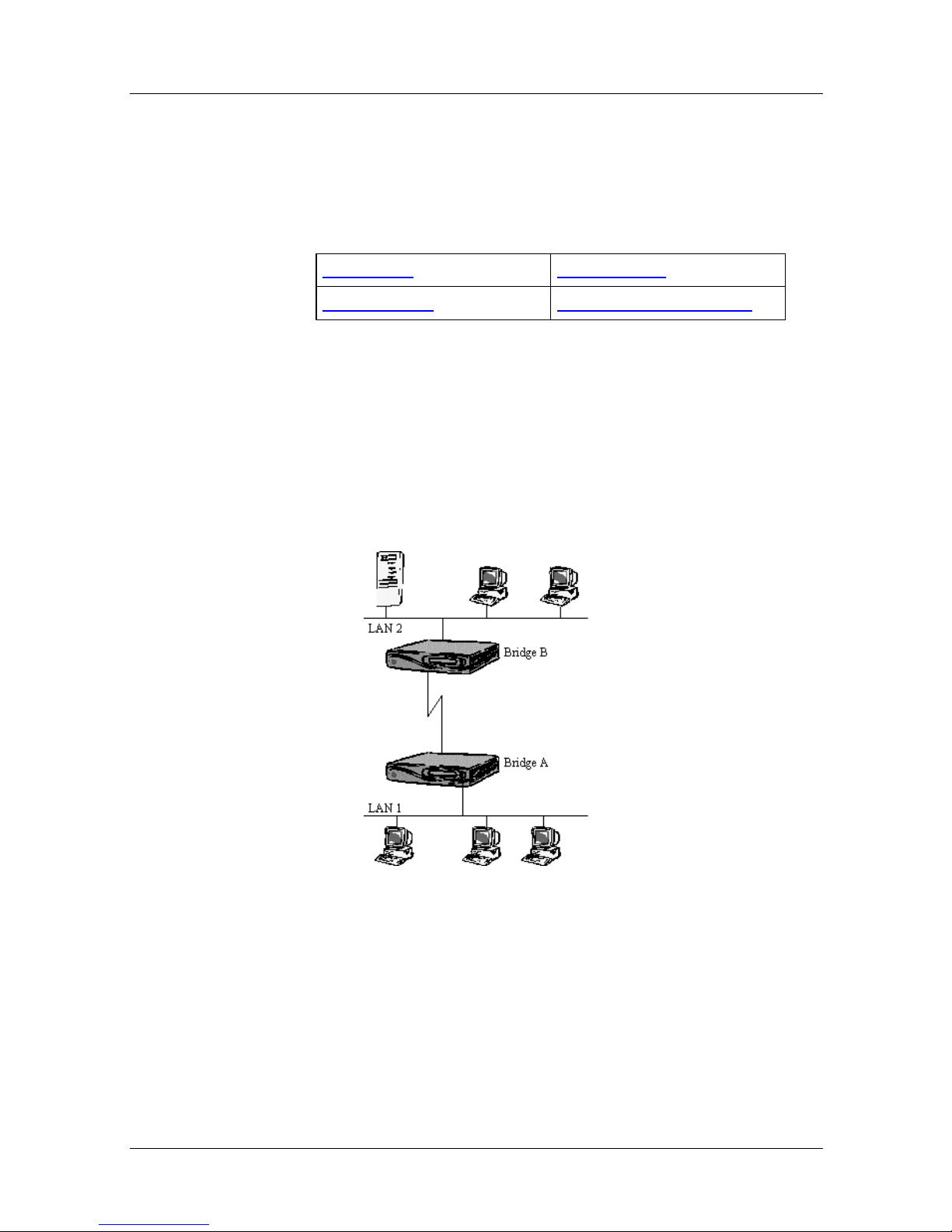
Figure 2-1. Bridge Pair with Single Link
After installation the bridges le arn quickly which devices are on
which LAN, and ensure that only data destin ed for the remote
LAN is transmitted on the serial link between the two bridg e s.
Data can be transported between LANs with n o filtering out of
frames ba sed on addresses or protocol types.
2-2 302976-A Rev.00
Page 37
Installation
The bridge hardware should be set up as a in the Installation
Guide. If the default Standard Configuration is used, no other
changes are required unless optional bridge features are needed.
For example, to use the remote management facility, IP addresses
must be assigned to the units. Also, if security is important,
manual configuration is needed to specify things like the type of
bridge filtering required, the manger password, and so on.
Parallel Links
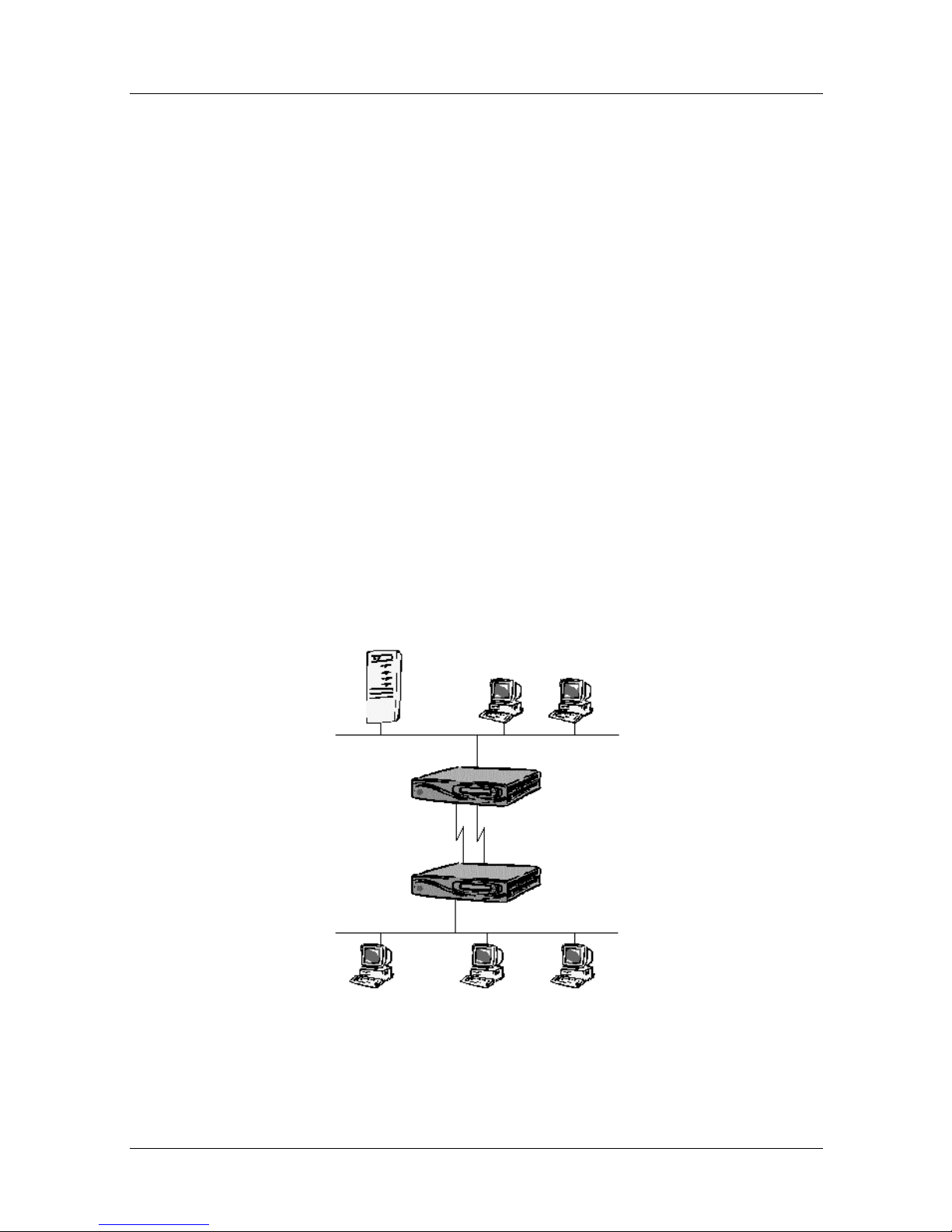
Provides more bandwidth between LANs than a SINGLE LI N K
configuration when traffic levels are very high and keeping
network delays to a minim um is important.
Bridging Network Designs
If one link fails, the other one will continue with out loss of data,
but network performance may be lower if the traffic level is
greater than one link can ideally support.
Figure 2-2. Bridge Pair with Parallel Links
302976-A Rev.00 2-3
Page 38

Nautica Marlin Bridge Reference Guide
When two bridges are connected in this way, they detect
automatically that they have multiple parallel links, and ensure
that frames passed between the bridges are handled correctly
(using the the Multilink protocol to ensure that frames are kept in
sequence).
If one link fails, all data is sent via the remaining link . The
Multilink protocol used on parallel links ensures that data in
transit is not lost, but is retransmitted o n th e rema ining link.
Installation
The bridge must be configured with at lest two serial port
interfaces. The hardware should be set up as in the Installation
Guide. if the default Standard configuration is used, no other
changes are required unless optional bridge features are needed.
This is a simple extension to the Single Link
bridge pair using the
default Standard Configuration. No configuation changes are
needed to set up this network. More than two links may be
connected in parallel if a WAN4 port expansion card is used.
Both links must operate at the same effective throughput. If one
line operates at a lower speed, or has a higher underlying error
rate, network deloys may increase while the bridge is recovering
lost or damaged frames.
Consider using an ISDN connection for the second link if two
leased lines are not required at all times.
2-4 302976-A Rev.00
Page 39
ISDN Backup
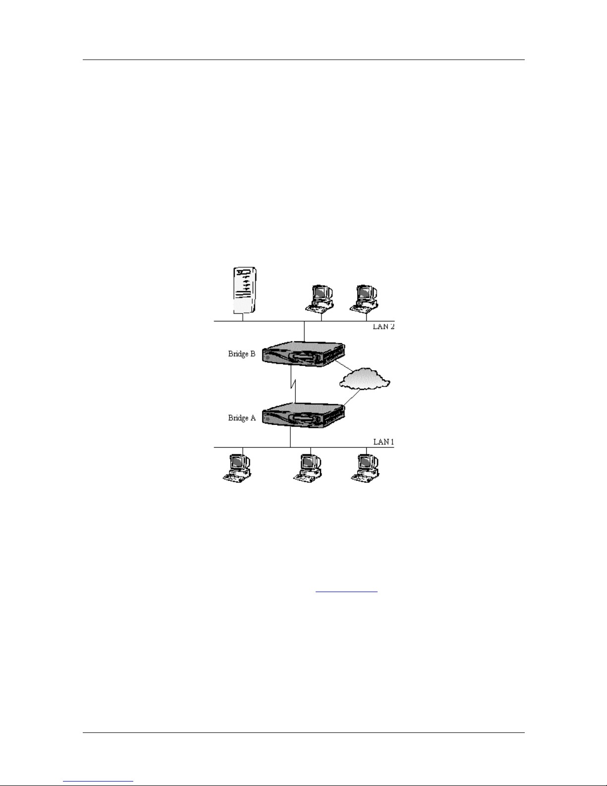
Uses on-demand connections via ISDN to avoid having circuits
permanently connected even when not in use.
The ISDN circuit can be used to provid e ban dwidth when need ed
(when the leased line reaches a loading threshold), and also for
circuit backup inthe event of a link failure.
Depending on distance, tim e and other f actors , using ISDN offers
significant cost savings over permanent leased lines.
Bridging Network Designs
Figure 2-3. Bridge Pair with ISDN Backup
Bridges pass frames of data between the two LANs, using the
lesed line circuit as in the Single Link example (more than one
leased line can be used if traffic levels demand this).
Bridges check usage of the links continuously and compare
loading with threshold values for each link. When this value is
reached, an ISDN connection is set up between the two bridges.
302976-A Rev.00 2-5
Page 40

Nautica Marlin Bridge Reference Guide
The bridges use this extra capacity by sharing frames for
transmission between the leased line and the ISDN channel.
Frame sequence are maintained by the bridges in the same w ay as
in the Parallel Links
Bridges use as many ISDN connections as needed to handle the
threshold values set for the links. A bridge can have up to three
Basic Rate ISDN interfaces which support a total of six ISDN
channels. An optional Primary Rate ISDN interface is available
that will support up to 30 (euro ISDN) and 23 (North American
ISDN) channels.
If the leased circuit fails for any reason, the bridges set up an
ISDN connection between themselves and continue operation
using this channel until the primary circuit is resto red. Then the
ISDN channel is closed, unless it must stay open to meet link
threshold requirements.
example given above.
This network is based on the default Standard Configuration.
Several parameters must be set up, and at least one ISDN Opti on
Card fitted to the bridges.
For each bridge port with ISDN backup, the ISDN address of the
remote bridge must be defined (see Chapter 4). Backup/Demand
Mode must also be set as required.
Backup Priority and Demand Priority settings are not relevant to
this simple case with ony two bridges. Though not essential, some
optimisation may be done to the threshold values to determine
when ISDN connections are set up and cleared. This affects
network performance: the lower the threshold, the sooner extra
bandwidth is allocated.
2-6 302976-A Rev.00
Page 41
ISDN Interconnect Only
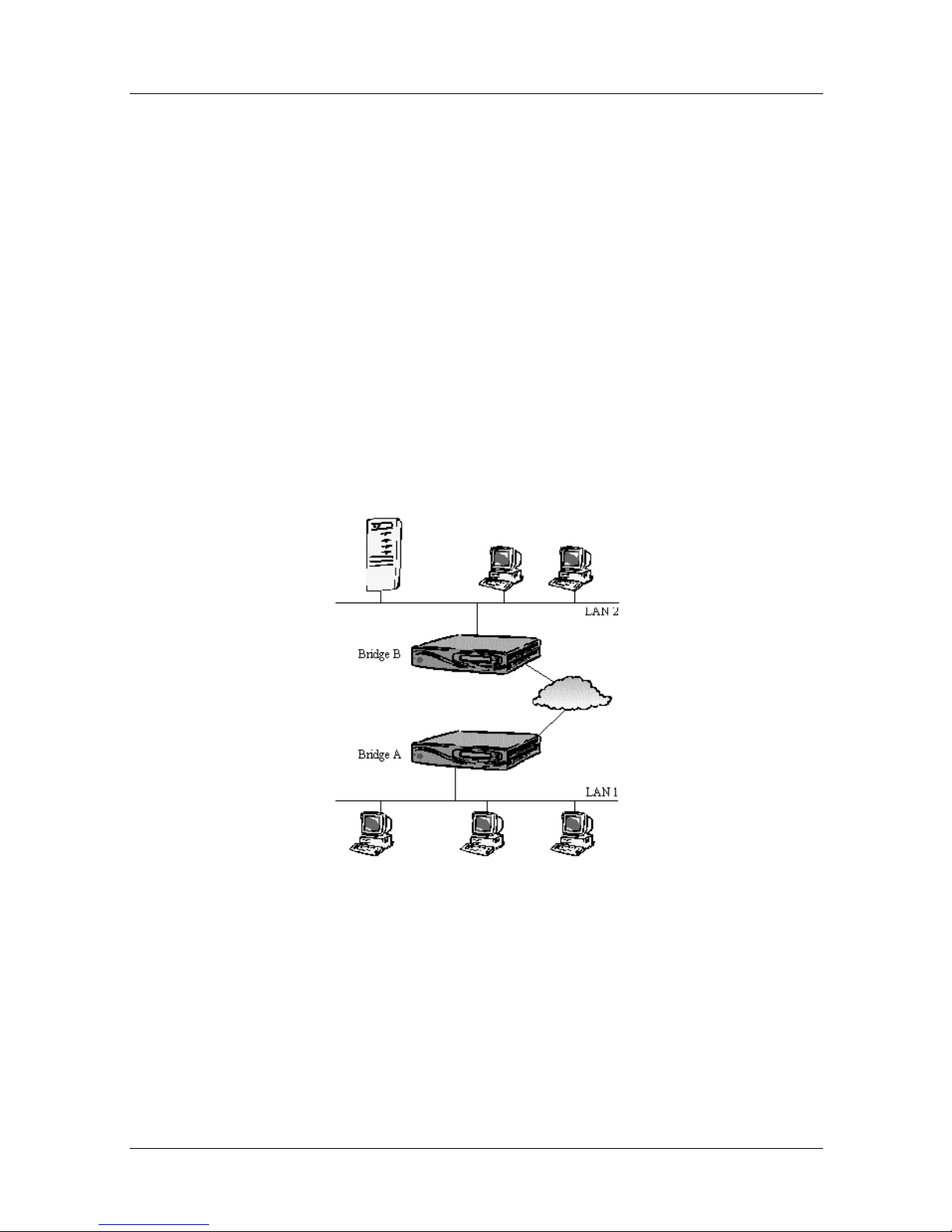
Allows an ISDN connection to be set up only when there is data
to transfer between two LANs. With no permanent link between
the two bridges, the high costs of permanent leased lines are
reduced.
This network is not restricted to a pair of bridges only. Special
handling of MAC addresses and specific protocols (IP, IPX,
ScaNet OSI, Banyan Vines) enables a network of ISDN-only
connected brdiges to be built and operated.
This is very useful for occasional remote site users who dial up
various hosts and central sites which in turn must dial up different
remote sites, e.g. to poll for information and status.
Bridging Network Designs
Figure 2-4. Bridge Pair with ISDN Interconnect Only
For certain protocols (IP, IPX, ScaNet OSI, Banyan) the brdige
recognises useful data packets, and automatically makes a call to
the relevant destination if the link is down.
302976-A Rev.00 2-7
Page 42

Nautica Marlin Bridge Reference Guide
For example, recognition of an Address Resoltuion Protocol
(ARP) packet can be configured. This allows a bridge to connect
to a destination brid ge, based on the IP address or IP su bnet of th e
destination host. This ISDN connection remains while there is
traff ic on th e link (measu red ov er a period of time), otherwise it is
cleared, so network usage is charged for only when the link is
actually in use.
A similar process can be enabled to allow the bridge to dial a
destination bridge, based on the destination MAC addresses in
received packets. This would be relevant if the protcol used was
not a standard one.
Manual calls can be made using the Marlin Bridge front panel
and/or management terminal. A list of configured destination
Marlin Bridges and their ISDN numbers is presented, from which
the required destination can be selected. Normally the procedure
would be carried out just before sending data between the local
and destination LANs.
As in the ISDN Backup
example, the ISDN dial-up numbers of
partner brdiges must be defined, but in this case the numbers are
associated with destination addresses in received packets, rather
than with permanent links. this is done using the Autocall facility
(Chapter 4).
If the manual call facility is used, then the ISDN Numbers Table
must be set up. Only the destination Marlin Bridge name and
ISDN numbers are required.
If security is important with ISDN dial-in, the Marlin Bridge’s
Authorisation Table must be set up with the MAC addresses of all
devices that are allowed to make ISDN dial-in calls to this unit.
With even one table entry, only calls from devices with MAC
addresses in the table are accepted (see Chapter 4).
Also, Calling Line Indentification (CLI) can be used to ensure
that the remote unit is calling from the expected number. CLI is
an option from the ISDN provider, and must be present for the
bridge CLI feature to operate.
2-8 302976-A Rev.00
Page 43

Bridging Network Designs
When the ISDN numbers of the rem ote units are added to the CLI
table, the Marlin Bridge only accepts incoming calls from these
numbers (see Chapter 4).
302976-A Rev.00 2-9
Page 44
Nautica Marlin Bridge Reference Guide
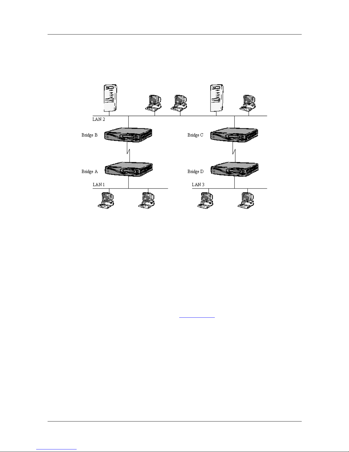
Multiple Bridge Pa irs Network
Networks with more than two LANs can be created very simply.
Figure 2-5. Multiple Bridge Pairs
In this example, LAN 2 is the central or main LAN to which other
LANs want access. LAN 1and LAN 3 are remote offices or
departments that need access to the central database.
The network consists of two simple bridge pairs with only one
path from each LAN to the other. If bridges A and B were the
original bridges as in the Single Link
example, then it is easy to
install bridges C and D. They function as part of the network
without reconfiguring bridges A and B.
All the bridges learn which devices are attached to their LAN and
which ones are at a remote LAN. Data for remote LANs is sent
down the serial link for the remote bridge.
2-10 302976-A Rev.00
Page 45

Bridging Network Designs
The two bridges attached to LAN 2 learn quickly which devices
are attached to the LAN and which are reached via serial links. So
frames from LAN 1 for LAN 3 are sent from bridge A to bridge
B, which gives the frame to LAN 2. Bridge C sees that the frame
is for a LAN 3 device and sends it on its serial link to bridge D.
Installation
This network is a simple extension of the Single Link example.
The same default configuration can be used if enhanced bridge
features are not needed.
ISDN and permanent parallel links can provide network
resilience and extra bandwidth (see previous examples). As this
network has no redundant loops, STA can be disabled.
302976-A Rev.00 2-11
Page 46
Nautica Marlin Bridge Reference Guide
Brdige Triangulation Networks
There are several examples of bridge triangulation. In the table
below, click on the optio n you require.
Simple Triangulation Multiple Triangul ation
Resilie nt Links Fully Resilient Triangulation
Fully Resilient With ISDN
Backup
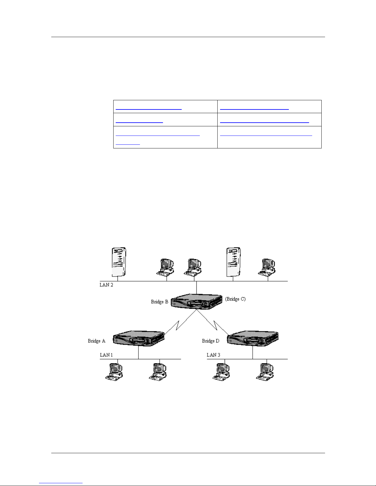
Simple Triangulation
Simple Bridge Triangulation reduces the number of bridges (and
the costs), while still achieving similar results to multiple bridge
pairs. the data between LAN 1 and LAN 3 no longer travels via
LAN 2, so better performance on LAN 2 is achieved. This is
called a Triangulated Network.
Cost Reduced ISDN Backup
Figure 2-6. Simple Bridge Triangulation
2-12 302976-A Rev.00
Page 47
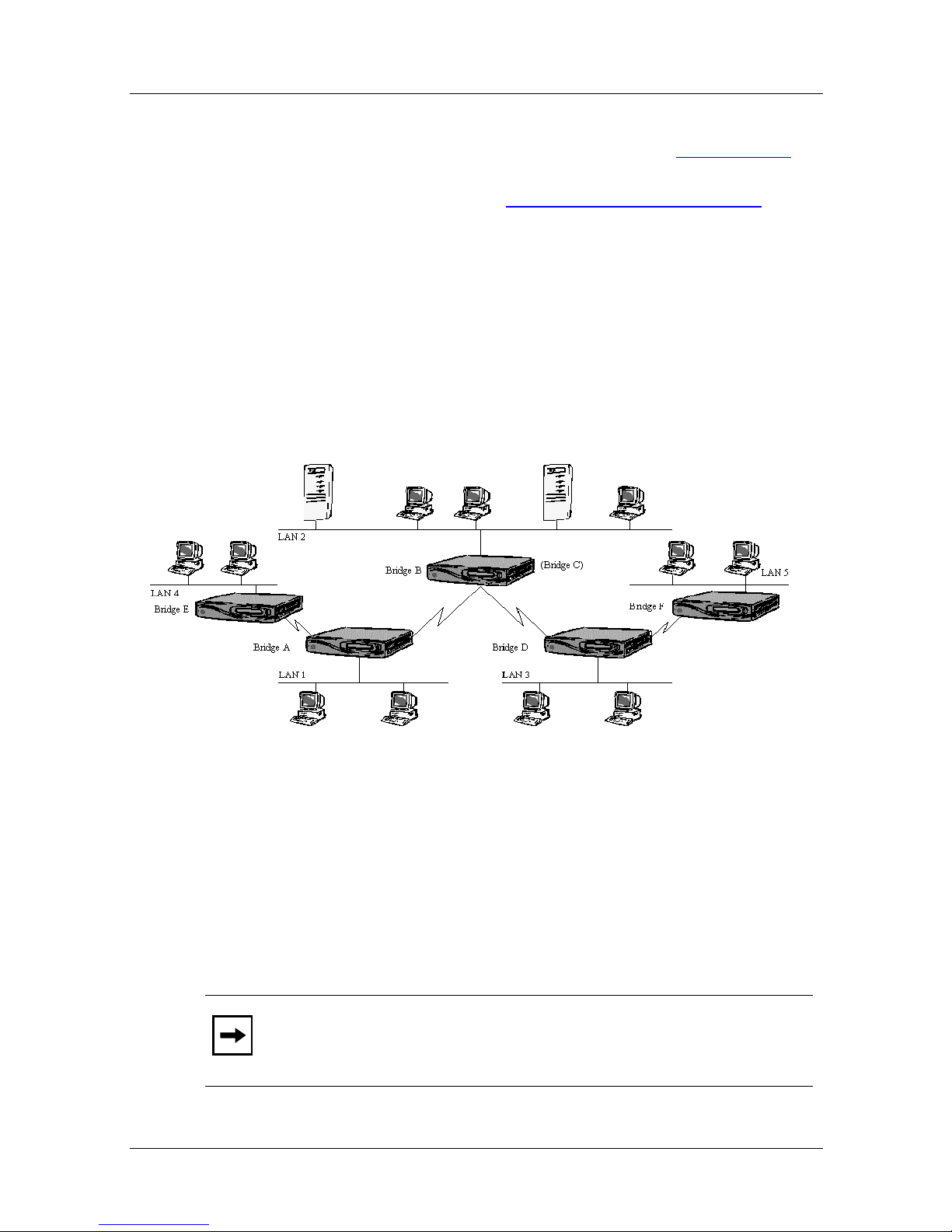
Bridge B acts as the remote bridge for both bridges A and D, and
appears to them to be a partner bridge, as in the Parallel Links
example. Brid ge B now funct ions as two bridges (bridges B and C
from the prev ious example Multiple Bridge Pairs Network
with the extra work of routing frames between LAN 1 to LAN 3
on its two serial ports, rather than placing them on LAN 2.
Multiple Triangulation
Using Multiple Triangulation, networks can be extended without
having to install two bridges for every link, so keeping costs to a
minimum.
Bridging Network Designs
), but
Figure 2-7. Multiple Bridge Triangulation
Bridges A, B and D all act as triangulated bridges, while bridges
E and F are configur ed no rmally. The triangulated bridges handle
their serial links in a similar manner to the LAN port, making
decisions about which serial or LAN interface to use for sending
data to its destination.
Note:
communication stops, mdue to the non-resilient design of the
network.
302976-A Rev.00 2-13
If intermediate links or brdiges fail, then inter-LAN
Page 48
Nautica Marlin Bridge Reference Guide
Resilient Links
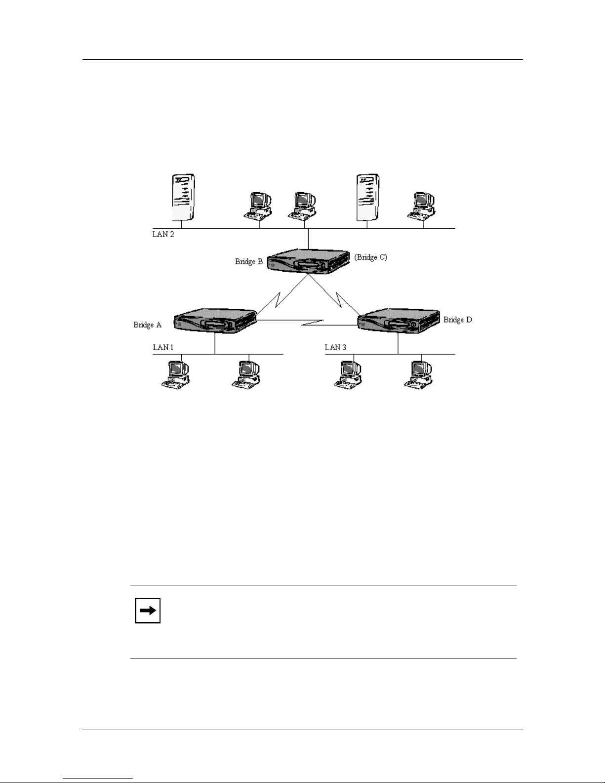
This example shows a network that is more resilient to link
failures than a simple triangulated bridge network; using an
alternative path to each LAN if one of the links fails.
Figure 2-8. Bridge Triangulation with Resilient Links
The Spanning Tree Algorithm (STA) sets up two active links and
one standby link out of the three links available, so there is only
one path around the network. If either active link fails, the STA
makes the standby link active and allows frames to be sent on it.
This ensures that data can still be routed to all LAN devices on
the network.
Note:
This network is not resilient to bridge failures, e.g. if
bridge B failed, then frames could pass between LAN 1 and
LAN 3, but could not be sent to or received from LAN 2, as it
would be isolated completely.
2-14 302976-A Rev.00
Page 49
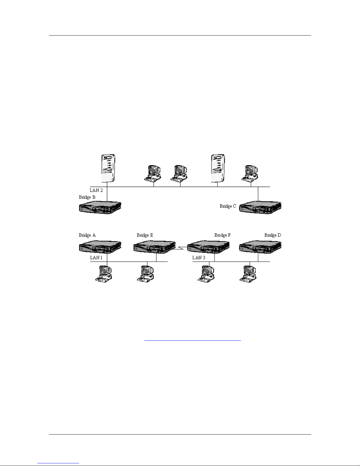
To optimize this type of network, us e ISDN to provide link
backup, rather than paying for an unused leased line. To provide
the same network topology, only two of the bridges need to have
the facility, i.e. the two bridges connected by the link that would
normally be unused.
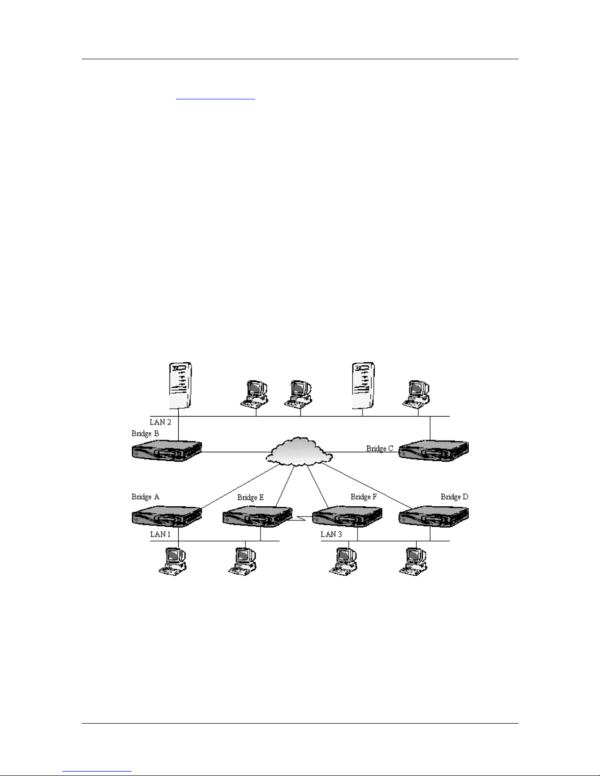
Fully Resilient Triangulation
This example shows a fully resilient network that continues to
operate if a link or a bridge fai ls.
Bridging Network Designs
Figure 2-9. Fully Wide Triangulation
Extends the Multiple Bridge Pairs Network
interconnects three LANs using two indepen dent bridge pairs.
Two extra bridges are added to the network to interconnect LAN
1 and LAN 3.
302976-A Rev.00 2-15
example, which
Page 50
Nautica Marlin Bridge Reference Guide
This network operates in much the same way as the previous
Resilient Links
example, where the STA disables one link to
remove the network loop. If any one connection between LANs
fails, because of either a link or a bridge unit failure, then STA
sets up an alternative path between all LANs.
Fully Resilient With ISDN Backup
ISDN can be used very effectively to provide bandwidth on
demand and link backup as shown here. Network resilience is
improved, as any leased line failures can be backed up by
dialled-up ISDN circuits, and bandwidth utilisation can be
optimised by using ISDN circuits only when network traffic
reaches defined threshold levels.
Each bridge has an ISDN Option Card to provide bandwidth on
demand and connections to all other bridges.
Figure 2-10. Fully Resilient Network with ISDN Backup
2-16 302976-A Rev.00
Page 51

Bridging Network Designs
For each bridge, basic operation is almost identical to that
described for the ISDN Backup
example, where ISDN is used to
backup failed links and provide bandwidth on demand.
The ISDN numbers of t he brid ge’s partners must be co nf igured in
all bridges (see Chapter 4). Backup/Demand Mode must be set
for bandwidth on demand and/or backup. ISDN parameters such
as threshold levels should also be set if needed.
The two bridges on LAN 2 can be connected to the same ISDN
line, using the facility which allows up to eight devices (bridges,
in this case) to be attached to one Basic Rate line; this reduces the
total number of channels available.
302976-A Rev.00 2-17
Page 52
Nautica Marlin Bridge Reference Guide
Cost Reduced ISDN Backup
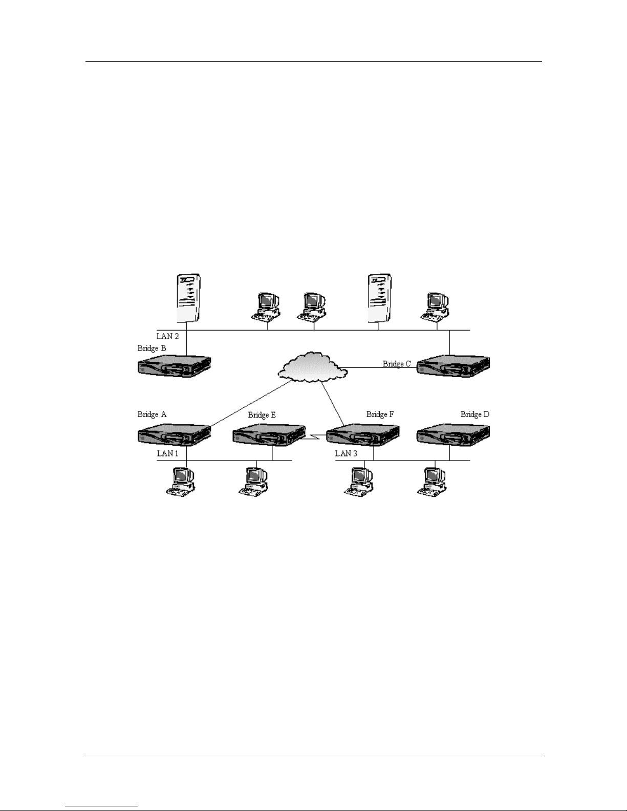
Provides the same functions as the previous network at less cost,
as the number of ISDN interfaces is reduced.
This configuration allows any bridge on a LAN to ask for an
ISDN connection to a bridge on the same LAN (there may be
many more bridges, but on y two are sho wn on each LAN). In this
way, bridges on a LAN can “share” ISDN interfaces to reduce the
overall cost. This is most useful when ISDN is being used for
backup, rather than for bandwidth on demand.
Figure 2-11. Cost Reduced ISDN Backup
When the leased line between bridges E and F fails, bridge E asks
bridge A to make an ISDN connection by giving it the ISDN
number of the remote b ridg e F. When the connection is made and
the STA has resolved the new network topology, bridges A and F
handle the data between LAN 1 and LAN 3.
2-18 302976-A Rev.00
Page 53

Bridging Network Designs
When the leased line between bridges E and F can be used again,
bridge E asks bridge A to close down the ISDN connection to
bridge F. Bridge A operates as a normal ISDN bridge, as it uses
its own ISDN interface as a backup circuit if its link to bridge B
fails.
Each LAN needs at least one bridge with an ISDN option card
installed (bridge A on LAN 1). All other bridges on the LAN
(bridge E on LAN 1) wishing to use the ISDN interface for
backup are set up with the MAC address of the bridge (bridge A)
and the ISDN number of the remote bridge to be dialled if their
leased lines fail (bridge F) (see Chapter 4).
To improve network security, each bridge’s “authorisation” table
must contain the MAC address of every other bridge which is
allowed to call that bridge. When this is done, a bridge will not
accept ISDN calls from any device with an unknown address (see
Chapter 4).
302976-A Rev.00 2-19
Page 54
Nautica Marlin Bridge Reference Guide
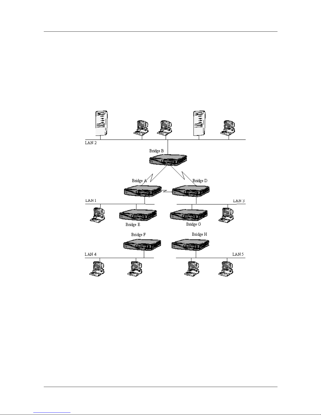
Multi-tiered Network
This type of network reduces the number and cost of leased lines
by carrying traffic from remote LANs on shared “backbone”
circuits. Resilience (failure tolerance) can be built into parts of the
network essential for business operations; small remote sites
could be given a lower cost but less resilient service.
Figure 2-12. Multi-Tiered Network
This is relatively simple to set up. STA resolves all routing issues,
especially around the backbone where resilient links are most
likely. STA ensures that only a single p a th exists b e tween any
bridge and the root bridge, so removing any loops in the network
which would cause problems such as packet duplication and loss
through time-outs.
2-20 302976-A Rev.00
Page 55

Bridging Network Designs
This example shows remote or “spur” LANs with only one link to
the backbone. In such a configuration, it is usually important that
the bridges on these remote LANs do not become the root bridge,
or inefficient paths for most of the network traffic may be set up
(to and from LAN 2 here).
This problem is solved b y setting suitable p riority values for each
bridge on the network. This Priority is used by STA to calculate
the network topology. If the bridges o n the backbone are giv en the
highest priority, STA can calculate a suitable topology.
In more complex networks than this one, it is important to ensure
that STA sets up a suitable root bridge and an efficient root
(primary) path. In this case, bridge priorities can be set maually to
help STA to set up a better path than it would be using bridge
addresses as the default priorities.
The remote bridges on spurs can have STA disab l ed, so that they
are not included in any root path calculations. This ensures that
only a backbone bridge can be the root bridge.
If usage is infrequent, or only at certain times of the day and for
relatively short periods, then use ISDN on remote bridges to dial
in to the backbone network.
302976-A Rev.00 2-21
Page 56
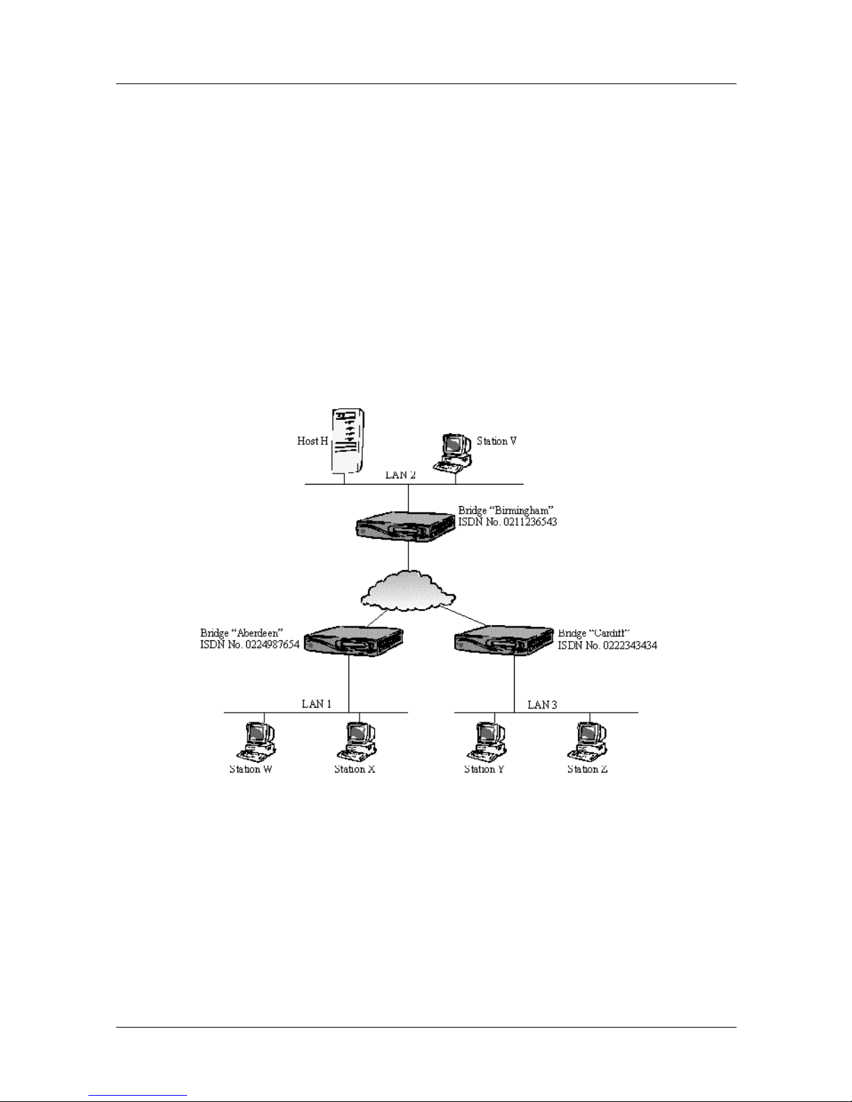
Nautica Marlin Bridge Reference Guide
Autocalls For ISDN Only Lan Interconnect
Marlin Bridge “Autocalls” make and control connections between
Ethernet LANs when ony ISDN is available.
The Marlin Bridge can interpret a number of different protocols
to find out when it should set up and close down ISDN
connections.
The Marlin Bridge can “spoof” (mimic or emulate) some devices
to reduce ISDN connection times, improve ISDN utilisation and
save costs. Each protocol needs different configuration and
handling.
Figure 2-13. Typical Bridge Network for ISDN Autocall
2-22 302976-A Rev.00
Page 57

TCP/IP Autocalls
The bridge starts a connection to a rem ote bridge when it r ecei v es
a TCP/IP ARP request packet for an IP address which has to be
defined in the Autocall Table. Once the connection has been set
up, the ARP packet will be sent.
Normally the destination responds with its MAC address which is
returned to the ARP originator, who does not know that a dial-up
connection has been made to carry out the request. If the address
has already been resolved, but the ISDN line has been dropped
(for example, if there was not traffic for 2 minutes), a subsequent
IP packet will make the line active again.
To set this up, add an en try to the ISDN Autocall table of the
Marlin Bridge for an IP address (specific host destination), an IP
subnet (group of hosts), or an inverse subnet (i.e. any host which
is not in the local subnet). Each entry should contain the IP
address of the destination and the ISDN number (or name ) of the
destination Marlin Bridge. The subnet mask is specified by
adding the number of significant bits to the IP address:
Bridging Network Designs
1.1.1.78/32 is a specific host 1.1.1.78
1.1.1.0/24 is a class ‘C; subnet 1.1.1.
1.0.0.0./8 is a class ‘A’ subnet 1
!1.1.0.0./16 is for any address not in class ‘B’ subnet 1.1
Novell IPX Autocalls
Allows ISDN-only connected IPX netw ork devices to
communicate. This is most useful for remote client workstations
wanting access to central site LAN-based servers on a part-time
basis, but any IPX-based server networks can be linked in this
way.
302976-A Rev.00 2-23
Page 58

Nautica Marlin Bridge Reference Guide
The Marlin Bridges act as Novell server o r ro uter “agen ts” which
broadcast routing and service information from the routers and
servers accessed using ISDN connections. The ISDN line will be
set up again only when actual data is to be sent between these
devices and wo rks t ations.
Also, Marlin Bridges respond to server “keep alive” polls instead
of the workstations, so allowing the ISDN connections to be
closed when no “real” data is being sent.
Autocall table setup is made much shorter and simpler by first
setting up manual ISDN calls between remot e clie nt site(s) and
the central server site(s) and/or between server sites. This allows
the Marlin Bridges to learn the locations of servers and routers on
the network (see Chapter 4).
Unasked-for information from servers can be used to start an
ISDN connection to a remote workstation by setting up the
workstation address in the server ’s local Marlin Bridge. On the
Marlin Bridge local to the server, set up an ISDN Autocall table
entry of type IPX-WS (Workstation) with the MAC workstation
address. Repeat for each workstation.
The Marlin Bridge can be set up to respond to “get nearest server”
requests from a client workstation in place of a remote ISDN
connected server (put a “!” in front of appropriate IPX-SAP entry
see Chapter 4).
SCANET OSI Name Service Autocalls
When a ScaNet named service request is seen by a Marlin Bridge,
and the requested name is in the ISDN Autocall table, it will start
a connection to the remote Marlin Bridge whose ISDN name is in
the table entry.
When the ISDN connection is made, the request will be sent on to
the remote LAN using this connection, so that th e service
provider can respond.
2-24 302976-A Rev.00
Page 59

Create an ISDN Autocall table entry of type “ScaNet” for each
named service supported at the remote LAN accesssed using the
ISDN network. These table entries are made at the Marlin Bridge
local to the stations requesting the service.
Banyan Autocalls
For netw orks running Ba ny an Vines, the Marlin B ridg e can be set
up to “learn” the structure of the Banyan network, and can
emulate the remote network when the link is down. The call will
be set up only when read data is being sent.
Create a single Autocall table entry of type “Ban_def” which
specifies the destination to be called when a Workstation begins a
new session. Then set Banyan Learning to ON. Set up calls to the
relev ant destinations, and leav e them active for at least 2 minutes.
In this time each Banyan Router/Server should have broadcast at
least once, which allows the bridge to learn the layout of the
network.
Bridging Network Designs
The Marlin Bridge will “spoof” (emulate) the learned remote
network topology when the link is do wn, and set up the link when
there is real data to send (see Chapter 4).
302976-A Rev.00 2-25
Page 60

Nautica Marlin Bridge Reference Guide
2-26 302976-A Rev.00
Page 61

Chapter 3
Manage r Operation
This section describes the management system and how to access
and use it.
The purpose of this section is to make the user familiar with the
management concepts which are common to all Nautica Bridge
products, not to describe the management facilities of the product
to which this manual refers.
This chapter includes the following sections:
• Introduction (page 3-2
• Menus and Forms (page 3-3
• Front Panel Operation (page 3-4
• Manager Teminal Operation (page 3-7
• Remote Terminal Management (page 3-14
• Disconnecting from the Manager (page 3-15
• SNMP Management (page 3-16
• Management System Security (page 3-16
• Control Characters in Text Strings (page 3-17
• Control Character Actions (page 3-17
)
)
)
)
)
)
)
)
)
)
302976-A Rev.00 3-1
Page 62

Nautica Marlin Bridge Reference Guide
Introduction
Access to the management system is available from:
• The front panel .
• A terminal attached to the local manager port.
• A remote network attached terminal.
• A management station that conforms to SNMP (MIB II)
standards.
A default configuration can be selected at the time of installation
to provide some, possibly all, of the parameters needed for a
given network.
If a local management terminal is not available, enough
parameters can be set from the front panel to allow access from a
remote management station or a terminal connected to another
Nautica Series Bridge. Depending on the product type, little (or
even no) configuration may be needed to make the unit
operational.
Much status and statistical information is also available via the
front panel display. This information can be very useful in
analysing network performance and status if a local management
terminal is not available.
To fully use the bridge features, more information about the
specific installation must be entered. This requires a
locally-connected asynchronous terminal, remote network
attached terminal or an SNMP management station.
3-2 302976-A Rev.00
Page 63

Menus And Forms
Menus are used to mov e around the managem ent system and gi ve
access to all of the configuration, status and statistical information
used by the bridge. This information is held in forms built up and
edited from a number of items.
Each menu lists the names of the next level menus. By choosing
an item from the required list, the next level menu is selected.
This new menu will also list menu items which may select lower
level menus, if any, and so on. A menu may contain a mixed list
of lower level menus and forms.
Menus consist of one or more pieces of static or dynamic
information. Static information never changes, for example men u
items that point to other menus which are always available.
Dynamic information changes or is changed, for example a list of
ports that increases as more option cards are fitted.
Manager Operation
Forms are found at the bottom of the menu tree, and are used to
display and edit system information. Forms provide the user with
one or more pages of in formation wh ich contain static (fixed) and
dynamic (changing) information, as well as fields that can be
edited.
Items or fields on a form can contain free format
(“unconstrained”) text or a fixed format (“constrained”) list. Free
format text is any text the user wants to enter, although most free
format text fields will check any text input by using certain rules,
e.g. only digits will be accepted in a numeric field.
A “constrained” field has a limited number of v alues that are held
in the system as a list from which the user can select a value. A
good example of such a list is the compression options which the
Marlin Bridge can support, where DISABLED, ENABLED and
FAST are allowed, but SLOW is not!
How the menus and forms are selected and displayed depends on
whether the front panel or a terminal is being us ed. Both
interfaces are described below.
302976-A Rev.00 3-3
Page 64

Nautica Marlin Bridge Reference Guide
Front Panel Operation
The front panel display can be seen as a window on the
management system’s menus and forms. The cursor buttons are
used to move the window around the menu system, until it comes
to a form where information can be displayed or changed.
FRONT PANEL DISPLAY
Figure 3-1. Typical Front Panel Display
Figure 3-1
The actual display format depends on the state of the unit and the
operations being performed. More information about
management menus, forms and status displays is given later in
this chapter.
shows a typical front panel display layout:
MENU NAVIGATION VIA THE FRONT PANEL
Normally the front panel “window” shows the Marlin Bridge’s
interface loading bar graph, which gives a quick indication of the
loading on external interfaces. If more information is needed, or
to change a parameter , then mov e the wind ow d own the menu tree
to the form containing the information.
To move around the menu system, press the UP and DOWN
cursor keys (the SELECT buttons on the front panel) to move the
cursor left and right. when the cursor is at the item to be
SELECTed, press the ENTER key. To go up a level in the menu,
press the UP key when the cursor is at the leftmost item.
3-4 302976-A Rev.00
Page 65
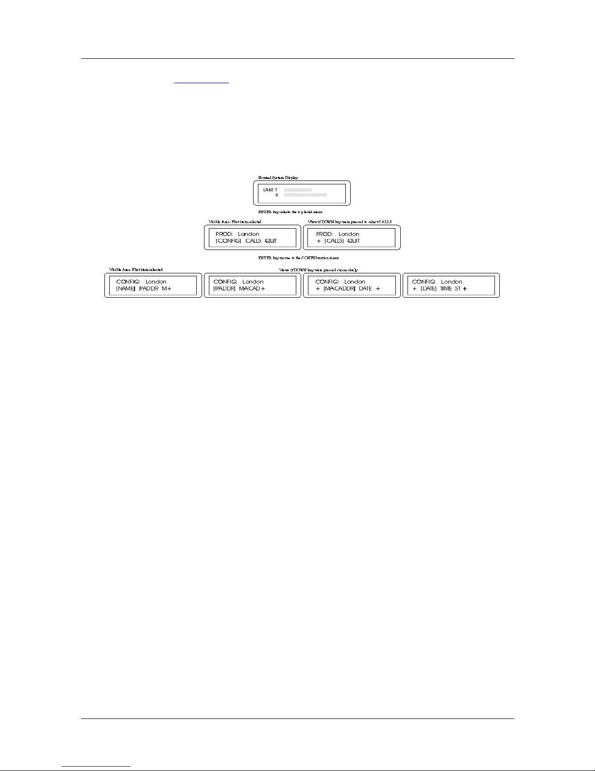
Manager Operation
Figure 3-2 shows how the window is moved around the menu
tree. Note that the CONFIGuration menu item is selected as
shown by the [square brackets]. Normally the window shows the
bar graph, and moves to the top level menu when the ENTER key
is pressed. Pressing ENTER again moves the window down the
menu tree to the CONFIG menu.
Figure 3-2. Front Panel Menu Navigation
At the top level menu, if the DOWN key is pressed instead of the
ENTERkey, then the window moves to the right to select the
CALLS menu [CALLS] and pressing the ENTER key again
moves the window down to that menu instead of the CONFIG
menu.
The plus (+) sign t o the r i ght and / or le ft of the display means that
there are more menu items available which are not yet under the
viewing window.
Form Display and Editing Via the Front Panel
A form consists of a number of fields or items of information.
Some fields ar e fi xed or generated b y the Marli n Bridge and canot
be changed by the user, while others may be set manually.
The use of cursor keys in a form field is a little diff eren t from a
menu. The UP and DOWN keys rotate the value in the field. The
way in which the value is rotated depends on the type of
information held inthe field.
302976-A Rev.00 3-5
Page 66

Nautica Marlin Bridge Reference Guide
If a field can contain an item from a limited (“constrained”) list,
the value is chosen by pressing the UP and DOWN keys until the
required value is shown, theN pressing the ENTER key. No other
values are allowed.
If a field is numeric, decimal digits 0 - 9 are displayed. If it is
hexadecimal, digits 0 - 9 and letters A to F are displayed. If it is
alphnumeric, letters A to Z, digits 0 - 9 and punctuation marks or
special characters are displayed.
Use the ENTER key to move the cursor from one character to the
next in the field. At the end of the field, the Marlin Bridge asks:
“Is this Correct?”. If so, hit the ENTER key.
Note:
Parameters are changed as soon as a new value is
entered. Some changes, for e xample, link operating p arameters,
may cause the network to stop working. Such major changes
should be made only after closing the network, when network
traffic is low, or after warning network users of potential
problems.
Saving Changes Via the Front Panel
After changing the current configuration, the top level menu adds
SAVE to its list of items, as in Figure 3-3
Figure 3-3. Front Panel After Config Change
:
The current configuration must be SAVEd in semi-permanent
memory if the Marlin Bridge is to use these values when it is
restarted, e.g. after a power failure. Do this by pressing ENTER
when the SAVE option is shown and selected [i.e. in square
brackets]. when the current configuration is SAVEd, the SAVE
option will not be shown.
3-6 302976-A Rev.00
Page 67

Interface Activity Bar Graph Operation
Normally the front panel shows the interface activity bar graph.
The display shows each interface (LAN1, WAN1, etc.) for two
seconds, as in Figure 3-4
Figure 3-4. Interface Activity Bar Graph
The bar graph show s the level of Transmit (T) and Receive (R)
activity. If the interface is inactive, it will be shown as DOWN.
.
Manager Operation
To hold the display for a given interface, simply press UP when
the interface is shown. This holds the display for five minutes,
then it continues to show each interface in turn. To cancel a hold
before five minutes, press UP again.
T o leav e the inter face acti vity bar graph mode, p ress any k ey other
than UP and the display returns to the top level menu.
Manager Terminal Operation
The local management terminal provides a system of menus and
forms for displaying and changing information in the unit. The
user moves around the management system by choosing menu
and form names which appear as items in m e nu lists.
Management system commands can be entered in menus, and
configuration details can be added and edited in forms.
The terminal screen for menus and forms is almost identical. Both
formats have s imilar features and the same screen regions.
302976-A Rev.00 3-7
Page 68

Nautica Marlin Bridge Reference Guide
Screen Description
Figure 3-5 shows the screen regions and forms, described below.
Product Name & Version Screen Title
Central Screen Region
Contains a Menu or Form
And Screen Specific
Commands
Menu Navigation Region
Commands & Responses
Figure 3-5. Terminal Management Screen Regions
Title Line Region
The product name, version number and screen title appear in a bar
at the top of the screen. The product name and v ersion nu mber are
different for each type of product. The screen title is different for
each menu or form.
Central Menu and Form Region
The central region of the screen holds system menus, forms and
commands. If it contains a menu list, then each men u item can be
one of the follo w ing:
Menu Name: Choosing this item asks the management system to
display the named menu. Each menu item has a short description
beside it to help the user find the right menu .
3-8 302976-A Rev.00
Page 69

Manager Operation
Form Name: Choosing this item asks the management system to
display the named form and the information it contains. Each
item has a short description of its function.
Command Name: A command that causes a management action
to be taken, depending on which command was entered, the state
1
of the unit and the current unit configuration
.
List Item: If there is more than one item of the same type, e.g.
two or more ports, these are listed in the form of a menu.
The central region of a form displays information such as port
configuration, unit status and statistics, etc. Depending on the
type of information displayed, this information may be changed
by the user.
Menu Navigation Region
This region shows the Control key (<CTRL>) commands that
allow the user to move up the menu tree. Some commands can be
used on all screens, but others can be used only at certain times
e.g. NEXT PAGE and PREVIOUS PAGE commands are shown
only when a form has more than one page.
See the full list of control characters and actions at the end of this
chapter.
Command and Response Region
This region shows command input and system responses to thos e
commands. It is not used on fo rms where input is entered directly
into the central region.
Command Line: Displays commands typed by the user. More
than one command at a time can be entered, using the system’s
type-ahead facility. The com mand or command list is ended by
pressing the <RETURN> or <ENTER> key.
Response Line: This tells the user about the previous command
entered, e.g. if an error is found.
302976-A Rev.00 3-9
Page 70

Nautica Marlin Bridge Reference Guide
Menu Navigation
Figure 3-6 shows a main menu list. To choos e an item, enter the
item name on the command line (where the cursor is positioned
already, waiting for input), then press the <ENTER> or
<RETURN> key, e.g. for COnfiguration:
CO<RETURN>
N.MAR.mmm SYSTEM NAME
CONF - Configuration
STATS
REMOTE
QUIT
- Status/Statistics Monitor
- Remote Management
- Disconnect
Enter command:
Figure 3-6. Main Menu (Example)
Main Menu
^G - Main Menu
^L - Prev Menu
Shorter item names can be used if the shorter name is still unique
to the menu system where it is entered, e.g. “REM” does the same
as typing “REMOTE”. See REFERENCE chapter for a full list
of menu item names and commands.
The user who is familar with the menu tree stru cture can go to an y
point in the menu tree by typing command lists, e.g. to go directly
to the ports list shown in Figure 4-8
CO PO<RETURN>
3-10 302976-A Rev.00
from the MAIN MENU, type:
Page 71

Manager Operation
This is called command type-ahead. It allows experienced users
to move around the menu system quickly witho ut using certain
menus.
N.MAR.mmm SYSTEM NAME
No. Name Type Phys. Rx(%) Tx(%) LZC(/) State
LAN1 LAN Port No. 1 Ethernet CSMA/CD 02.4 00.0 UP
[WAN1 HDLC Link 1 Bridge HDLC X.21 00.2 01.8 4.5 UP]
ISDN1 TA Link 1 Bridge TA ISDN 00.2 02.9 2.6 UP
ISDN2 TA Link 2 Bridge TA ISDN 00.0 00.0 DOWN
(co po) Enter Command:
Port Configuration
Page No. m of n
^G - Main Menu
^L - Prev Menu
Figure 3-7. Variable List Menu (Example)
When a menu list such as this one has a v ar iable number of items,
the item required is selected as follows. One way is to use the
keyboard cursor (up) and (down) keys, to move through the list
until the item is between the [square brackets] at the beginning
and end of the line. Also, the li ne is highlighted using inverse
video if the terminal supports this feature. When the item is
selected, commands can be entered, e.g.
EDIT<RETURN>
Another way is to enter the item identification number after a
command, e.g. to edit port WAN1, type:
EDIT WAN1<RETURN>
302976-A Rev.00 3-11
Page 72

Nautica Marlin Bridge Reference Guide
This does the same as moving the cursor to line WAN1 using the
cursor keys. W hate v er metho d is used, the management system in
this example displays a form showing the selected port’s
configuration, which can then be edited.
Form Navigation And Editing
When a form is shown, it can have any number of fields to be
displayed or edited. the form name is in th e title bar at the top of
the screen. Each field and its name is shown in the central region.
Figure 3-8
shows a typical form:
N.MAR.mmm SYSTEM NAME
P o rt Number
Port Name
STP Priority
Line Speed (bits/s)
Compression
Backup/Demand Mode
Backup Bridge
Remote Unit Name
^E - Submit ^G^L- Main Menu
: WAN1
: HDLC Link 1
: 128
: 64000
: Enabled
: None
: 002062009999
: Central_Site
Edit HDLC Port
Demand Threshold
Demand Period
Idle Threshold
Idle Period
Demand Priority
Backup Priority
Backup Alert
: 50%
: 10
: 2%
: 60
: 0
: 0
: Enabled
- Prev Menu
Figure 3-8. HDLC Port Configuration Form (Example)
When a form is shown on the screen, the cursor is set to the first
field that can be edited: it can be moved to other fields using the
and, and cursor keys, and/or the <TAB> key. Read-only fields
(which cannot be changed by the us er) will be skppped o v er. field
editing can be done in various ways, depending on the type of
field and what is easiest for the user.
3-12 302976-A Rev.00
Page 73

Manager Operation
If the field is a “constrained” list (fixed format), the list of values
allowed is shown by pressing the <SPACE> or \ (backslash) key
once for each value in the list. Or, the v alue can be typed, and if it
is the same as one of the values in the field’s list, it will be
accepted. if not, an error message is given.
If the field is “unconstrained” (free format), the and cursor keys
will move the cursor within the field. When the cursor is at the
character to be edited, a new character can be entered. Or, the
whole field can be cleared using <CTRL>+U and a new field
value entered. or, type (CTRL)+R to restore the field to its
original value.
System information is configured b y changing the v alues of f ields
stored in forms. Changes are made only after “SUBMITting” the
form: press <CTRL>+E to make the changes, exit the form and
return to the previous screen.
Note: Parameters are changed as soon as a new value is
entered. Some changes, e.g. link operating parameters, may
cause the network to stop working. Such major changes should
be made only after closing the network, when network traffic is
low, or after warning network users of potential problems.
When system information is chan ged, it must be saved in the
Marlin Bridge’s semi-permanent memory if it is to be used when
a system restart is done e.g. after a power failure. When changes
are made, this message appears:
“Please save new configuration (SAVE)”
This is repeated on every menu screen until the SAVE command
is entered:
SAVE<RETURN>
302976-A Rev.00 3-13
Page 74

Nautica Marlin Bridge Reference Guide
Remote Terminal Management
The management system has a built-in TCP/IP Telnet feature
which allows it to connect to remote devices, so as to manage
those devices without stopping the current local management
session.
If the remote device is a Nautica Series Bridge, its name, IP and
MAC addresses appear in a list which allows the user to select
and connect to the device. If the remote device is not a Nautica
Series Bridge or compatible device, its IP address and TCP port
number can be entered directly.
The remote devices list is built automatically by the local Marlin
Bridge, and displ ayed by typin g REM<RETURN> to show a list
like that in Figure 3-9
needed, except to add the names and IP addresses of the Marlin
Bridges on the network.
below. No management system changes are
N.MAR.mmm SYSTEM NAME Remote Units
Page No. m of n
Unit Name IP Address MAC Address
[London 123.123.123.123 123456789012 ]
New_York 12.34.45.67 123456712345
Enter unit name or REM <name> or REM <ipaddr (port)> to connect
^N - Next Page
^P - Previous Page
(rem) Enter Command:
^G - Main Menu
^L - Prev Menu
Figure 3-9. Remote Devices Selection Screen (Example)
To connect to a remote device or host system, simply type its
name, e.g.
3-14 302976-A Rev.00
Page 75

Manager Operation
NEW_YORK<RETURN>
If the unit to be connected is not in the list (for example, if the
remote device is not a Nautica Series Bridge or compatible
device), i t can be connected by t yping its IP addr ess and TCP port
on the command line e.g.
1.2.3.4 23<RETURN>
When familiar with the names of the Marlin Bridges in the
network, these can be connected using commands anywhere int
he menu tree (not only from the Remote Units screen) by typing
“REM” before the name of IP address, e.g.
REM NEW_YORK<RETURN>
or
REM 1.2.3.4 23<RETURN>
The local unit can also be managed from any remote network
connected device with TCP/IP Telnet protocol, including
Terminal Servers, PCs with suitable emulation software, or
another Marlin Bridge or compatible unit.
When a connection to the local unit’s management system is
made, then management from a remote network attached
terminal, PC emulating a terminal or remote unit is the same as
using a local management terminal.
Disconnecting from the Management System
If logged on to the local Marlin Bridge’s manager, disconnect by
typing:
QUIT <RETURN>
If logged into a remote Marlin Bridge using the remote
connection facility, QUIT disconnects from the remote Marlin
Bridge and returns to the local Marlin Bridge manager, to connect
to another unit or manage the local unit.
302976-A Rev.00 3-15
Page 76

Nautica Marlin Bridge Reference Guide
Note: it is also possible to d isconnect from the remote unit with
<CTRL>+D. This makes TCP/IP Telnet (and not the Marlin
Bridge) abort the connection, so it should be used only when
QUIT does not work.
Snmp Management
It is possible to manage the unit using SNMP (Simple Network
Management Protocol) over the network. Management
Information Base (MIB) standards MIB I and II are supp orted, as
well as the BRIDGE MIB (RFC 1286) and private extensions.
Refer to your supplier for details of published MIB information.
Management System Security
Access to the terminal amangement system is protected by
password. An yone l ogging on to th e system mu st enter the correct
password as their first action. The user may try up to three times,
then the system stops the session.
The user is asked to enter the password as follows:
Enter Password [PASSWORD<RETURN>]
Here, the user has entered the default value “PASSWORD”.
Change this password to a more secure and priv ate one as soon as
the unit is installed.
3-16 302976-A Rev.00
Page 77

Control Characters In Text Strings
To enter control characters into text string fields, each one must
start with the ^ (caret) character. The two-character combination
(of caret and alphabetic character) is translated into one control
character by the management system.
The management system only allows control characters in text
strings in certain cases, e.g. in strings such as a login banner
which are sent to the terminal, and where a CLEAR SCREEN
control character is used to clear the screen before displaying the
text. In other text strings such as the Unit Name, control
characters are stored and displayed as their text characters only.
CONTROL CHARACTER ACTIONS
Manager Operation
The table below lists the control characters (<CTRL>+key)
accepted by the system, an d their ac tions when used in a Men u or
Form.
Control
Char
A Turn VT100 /Televideo
B In a variable list menu,
C None Cancel Form - Leave the
Action In Menu Action In Form
Same as menu action
Terminal Mode ON or
OFF
None
moves tothe previous
page. If on the first page,
will movwe to the last
page
form and go to the
previous menu without
saving any changes
302976-A Rev.00 3-17
Page 78

Nautica Marlin Bridge Reference Guide
Control
Char
Action In Menu Action In Form
E None SUBMIT F orm - Changed
parameters are stored in
current configuration
memory. Note: Changes
are made immediately
G Go to the top level menu Leave the form and go to
the top l evel menu
without saving any field
changes
H None Backspace in field,
deleting characters
I None Same as <TAB>
character
L Go to previous screen Leave the form and go to
the previous menu
without saving any
changes.
M Typed command line text
Move to the next field
will be submitted for
processing
N In a multi-page form,
None
move s to the ne xt page. If
on last page mo ves to the
first page
R Recall the l ast command
entered
Recall the last value
stored in the field where
the cursor is located.
Values can be recalled
until the form is submitted
with <CTRL E>, after
which the new value is
recalled.
U Delete command line text Delete field value
3-18 302976-A Rev.00
Page 79

Manager Operation
Control
Char
Action In Menu Action In Form
V Repaint the screen.
Refreshes the screen if
terminal is used for
switching (hot-keying)
between this and other
systems
W Display on-line help
window. If multi-page
help is available, then
repeating command will
show successive pages.
Same as menu action
Same as menu action
302976-A Rev.00 3-19
Page 80

Page 81

Chapter 4
REFERENCE
The management options available via the Marlin Bridge’s front
panel are not as comprehensive as those via a terminal interface.
They do, ho wev er , enable the Merlin Bridge to be conf igured such
that it can become operational.
This chapter includes the management of the Basic Rate ISDN
Option Cards which may not always be present. If they are not
present, the management system will not include them in the lists
of installed ports .
This chapter includes the following sections:
• Main Menu (page 4-2
• Configuration (pag e 4-3
• Status and Statistics Monitor (page 4-66
• Connect to Remote Devices (page 4-79
)
)
)
)
302976-A Rev.00 4-1
Page 82

Nautica Marlin Bridge Reference Guide
Main Menu
N.MAR.mmm SYSTEM NAME
CONF - Configuration
STATS
REMOTE
QUIT
- Status/Statistics Monitor
- Remote Management
- Disconnect
Enter command:
Figure 4-1. Main Menu Screen
Main Menu
^G - Main Menu
^L - Prev Menu
CONF: Provides access to the configuration facilities within the
management system
STATS: Gives access to the status and statistical informaion
maintained by the unit.
REMOTE: Accesses the Remote Connect feature, allowing you
to connect to other TCP/IP Telnet devices on the network.
QUIT: This will close down the current management session. If
accessing a remote device, the network connection is closed and
control is passed back to the original unit.
See Chapter 3 for more detail.
4-2 302976-A Rev.00
Page 83

Configuration
REFERENCE
N.MAR.mmm SYSTEM NAME
STD - Standard Configuration
Configuration
SYS - System Parameters
PORTS
BRIDGE
ISDN
SNMP - SNMP System Parameters
- Configure Ports
- Bridge Confi gur at io n
- ISDN Bridge Configuration
(co) Enter command:
Figure 4-2. Configuration Menu Screen
^G - Main Menu
^L - Prev Menu
STD: Resets the Marlin Bridge’s current configuration back to
the default factory settings.
SYSTEM: (page 4-4
) Selects the common parameters found on
all product variants: manager password, date, time, etc.
PORTS: (page 4-6
) Allows access to all port configuration
parameters.
BRIDGE: (page 4-21
) Allows access to configurable bridge
features.
ISDN: (page 4-37
) Allows access to configurable bridge ISDN
features
SNMP: (page 4-63
) Allows access to SNMP configuration
parameters.
302976-A Rev.00 4-3
Page 84

Nautica Marlin Bridge Reference Guide
System Management
N.MAR.mmm SYSTEM NAME
Date (dd/mm/yyy)
Time (hh:mm:s s)
: 13/08/1998
: 15:49:23
Day of the Week : Thursday
Old Password
New Password
ReType Password
Idle Timeout (sec)
LCD Manager Lock
^E - Submit ^G - Main Menu
: PASSWORD
:
:
: 900
: Disabled
System Parameters
Unit Name
Unit IP Address
Ethernet Address
Node ID.
Def. ISDN Alert
Recv. ISDN Alert
Time Since Reboot
: System_Name
: 1.1.1.1
: 002062xxxxxx
: 0
: Beep
: Enabled
: 4:45:19
^L - Prev Menu
Figure 4-3. System Parameter Form
DA TE/TIME: The Date and Time can b e changed b y enter ing the
date or time. Submit the form (<CTRL>+E) at the instant the time
is correct for accurate seetting
OLD PASSWORD: When changing the password, the current
password must first be entered in this field. This will not be
printed when typed. An indication that the password is invalid
will only be given when the form is submitted.
Default: PASSWORD
NEW PASSWORD and RETYPE PASSWORD: The new
password is entered and retyped (for confirmation). The new
password will take effect only after you have logged out of the
current session with the manager. However, note that anyone else
logging on as manager will be required to enter the new
password.
4-4 302976-A Rev.00
Page 85

REFERENCE
IDLE TIMEOUT: After this time (in seconds), if there has been
no input from the manager terminal, the manager session will be
closed.
LCD MANAGER LOCK: If the LCD manager is locked, it is
impossible to change the IP address, Name, Date/Time or make
ISDN calls from the front panel. Options: lock ENABLED, lock
DISABLED.
UNIT NAME: An alphanumeric name given to the unit. The
name will appear on most user and manager screens and is used
for easy referencing of units in the network. It should be unique
among the Nautica series Bridges that may be connected.
UNIT IP ADDRESS: The standard TCP/IP interface address of
the unit. It is used as the default for IP Routing to access the local
management system (Telnet and SNMP) for the unit over the
network.
ETHERNET ADDRESS: This is the unit’s unique base Ethernet
address, which is configured into the unit hardware at the time of
manufacture and cannot be changed manually.
TM
NODE ID.: Applies only to the C-Gate DCX
gatew ay product .
DEF. ISDN ALERT: When making ISDN calls, this controls the
default han dling of the front panel alert LED and audible alert.
Used when making ISDN calls where there is no other specific
alert control parameter, e.g. when initiating a manual ISDN call.
Options: DISABLED, ENABLED and BEEP.
ENABLED causes the front panel alert lamp to flash when an
ISDN call is attempted. BEEP causes the alert lamp to flash and
the unit to beep every time the ISDN channel status is displayed
on the front panel (as part of the port status cycle).
REC. ISDN ALERT: When receiving ISDN calls, this controls
the handling of the front panel alert LED and audible alert (see
Default ISDN Alert above). Options: DISABLED, ENABLED
and BEEP.
302976-A Rev.00 4-5
Page 86

Nautica Marlin Bridge Reference Guide
TIME SINCE REBOOT: This is the time in hours:mins:secs
since the Marlin Bridge was last rebooted.
Port Management
N.MAR.mmm SYSTEM NAME
No. Name Type Phys. Rx(%) Tx(%) LZC(/) State
LAN1 LAN Port No. 1 Ethernet CSMA/CD 02.4 00.0 UP
[WAN1 HDLC Link 1 Bridge HDLC X.21 00.2 01.8 4.5 UP]
ISDN1 TA Link 1 Bridge TA ISDN 00.2 02.9 2.6 UP
ISDN2 TA Link 2 Bridge TA ISDN 00.0 00.0 DOWN
EDIT - Edit Port TYPE - Change Port Type
(co po) Enter Command:
Port Configuration
Page No. m of n
^G - Main Menu
^L - Prev Menu
Figure 4-4. Ports List Screen
This screen provides an o v erv ie w of the curr ent operation al status
on the ports on the system, as well as enabling a port to be
selected for configuration editing. The port currently selected is
highlighted and in [square brackets].
The information present ed on this screen is br iefly descr ibed with
individual port type configuration editing described in the
sections that follow.
Note:
is submitted (<CTRL>+E). Therefore you should ensure either
that ports to be edited are not being used, or be aware that data
may be discarded when a port is reset.
4-6 302976-A Rev.00
Port parameter edits will take effect immediately a form
Page 87

REFERENCE
Note: The commands available depend upon the port (type)
selected.
If a PRI TA is installed in the unit, it will be aut omatically
detected and the appropria te number of ports s upported b y the TA
will be displayed in addition to any other ports on the unit. The
number of ports is dependant on the quantity of channels for
which the PRI TA has been keyed, i n addition, not all of the key ed
ports may have been activated.
NO.: A unique name or identifier for the port on the unit. This is
generated automatically by the system, based on the hardware
configuration of the unit, and cannot be changed manually.
A port number refers to a single channel of communication into
or out of the unit rather than a phy sical interface. F or e xample, the
two channels of an ISDN interface are given individual port
numbers.
NAME: A user-friendly name that can be configured by the user
for easier referencing of the port.
TYPE: A type of port. There may be many types of port,
dpeending on the hardware configuration of the unit and the
software variant running on it. The type of port is not the
hardware type, but is related to it. For any particular physical
hardware port there may be a numb er of types that are applicable.
The TYPE command is only available on this screen if the port
type can be changed. For example, the wide area port on the
motherboard can be configured to be HDLC, PPP or TA, so the
TYPE option will be available. The Ethernet port, however, has
its type set automatically and cannot be changed.
302976-A Rev.00 4-7
Page 88

Nautica Marlin Bridge Reference Guide
Internal ISDN ports should be set to TA or NONE.
Note: For demonstrating or testing ISDN between two Nautica
series Bridges connected to the same ISDN line, set the second
ISDN port on the calling bridge to NONE so that it will not
answer its own call.
PHYS.: The physical layer type for the port. The Marlin Bridge
supports IEEE 802.3 CSMA/CD in the case of the Ethernet port,
and X.21 in the case of the WAN port.
RX (%) Tx(%): The Rx (receive) and Tx (transmit) fields
provide indications of the level of percentage utilisation of port
bandwidth. More information about port performance can be
found later in this chapter under STATISTICS (page 4-66
).
LZC(/): Provides an indication of the current compression ratio
being achiev ed on the links when Lempel-Ziv data compr ession is
enabled.
ST ATE: Indicates the current state of the port. The state will be
DOWN if the port is being reconfigured. Note
: a link configured
as BRIDGE PPP will not indicate a state.
4-8 302976-A Rev.00
Page 89

LAN Ports
REFERENCE
N.MAR.mmm SYSTEM NAME
Port Number
Port Name
STP Priority
Line Speed (Bits/s)
^E - Submit
Edit Ethernet Port
: LAN1
: LAN Port No. 1
: 100
: 10000000
Figure 4-5. LAN Port Configuration Form
Page No. m of n
^G - Main Menu
^L - Prev Menu
Port Number: The port number in the system. It is generated
automatically by the system and cannot be configured.
Port Na me: A name given to the port for ease of reference.
STP Priority: Used by the Spanning Tree Algorithm to help
determine which root port to use when calculating the root path.
The lower the number, the higher the priority.
LINE SPEED: The line speed is used to calculate the Spanning
Tree path cost for the Ethernet port. Used by the Spanning Tree
Algorithm, the path cost is used to he lp calculate the unique root
path through the networ k.
302976-A Rev.00 4-9
Page 90

Nautica Marlin Bridge Reference Guide
HDLC Ports
N.MAR.mmm SYSTEM NAME
P o rt Number
Port Name
STP Priority
Line Speed (bits/s)
Compression
Backup/Demand Mode
Backup Bridge
Remote Unit Name
^E - Submit ^G^L- Main Menu
: WAN1
: HDLC Link 1
: 128
: 64000
: Enabled
: None
: 002062009999
: Central_Site
Edit HDLC Port
Demand Threshold
Demand Period
Idle Threshold
Idle Period
Demand Priority
Backup Priority
Backup Alert
: 50%
: 10
: 2%
: 60
: 0
: 0
: Enabled
- Prev Menu
Figure 4-6. HDLC Port Configuration Form
Port Number: The port number in the system. It is generated
automatically by the system and cannot be configured.
Port Na me: A name given to the port for ease of reference. It is
not used by the system, other than on management screens.
STP PRIORITY: Used by the Spanning T ree Algor ithm, the path
cost is used to help calculate the unique root path through the
network.
LINE SPEED (bits /s) : This parameter should be set to the actual
line speed that the interface is being clocked at. Although the
Marlin Bridge does not generate clocks (oth er than a fixed 19.2
Kbps V.24 clock) this parameter is used to configure internal
timers which optimise use of the link.
COMPRESSION: Data compression can increase the effective
bandwidth of the port typically between 2 and 8 times. The de gree
of compresssion that can be achieved dpends largely on the
format of the data being transferred and the speed of the link.
4-10 302976-A Rev.00
Page 91

REFERENCE
DISABLED turns data compression off.
ENABLED allows the system to use its standard bandwidth
optimisation algorithm for compress ion. This should be used on
all links up to 256K bps.
FAST should be used on links with speeds greater than 256 Kbps
to maintain maximum throughput on the line. The advantage of
using compression depends on the data type and line speed
increases. You should monitor the effect of turning compression
on and off, particularly at line speeds over 256Kbps.
BACKUP/DEMAND MODE: Specifies if Backup of this port
and/or Bandwidth on Demand is allowed when dial-up ports are
available, e.g. ISDN. Also specifies if EXPEDITED or
NON-expedited data will cause the system to dial up Backup and/
or Bandwidth on Demand when threshold values are reached.
NONE disables these options.
BACKUP allows the system to dial the Remote Unit Name
destination (see below) if the link fails.
DEMAND allows the system to dial up additional band width to
support this link if the configured Demand Threshold values are
met (see below).
BOTH enables both BACKUP and DEMAND. If it is used, you
can set Backup Priority and Demand Priority (see below).
EXP.DATA means that when Demand Threshold values are met
(see below), packets defined as EXPEDITEd in the Ty pe Filter
Table will be sent by the first additional link dialled up. It also
allows the use of the BACKUP facility to dial the Remote Un it
Name destination (see below) if the usual link fails.
NON-EXP.DATA means that when Demand Threshold values are
met (see below), packets defined as NON-expedited in the Type
Filter Table wil be se nt by the first addition a l link dialled up.
302976-A Rev.00 4-11
Page 92
Nautica Marlin Bridge Reference Guide
NON-EXP+BKUP means that when Demand Threshold values
are met (see below), packets defined as NON-expedited in the
Type Filter Tab le will be sent by the first additional link dialled
up. It also allows the use of BACKUP facility to dial the Remote
Unit Name destination (see below) if the usual link fails.
REMOTE UNIT NAME: The name or ISDN number of the
remote partner bridge, unless the Backup/Demand Mode
parameter is set to NONE.
Note: The name must be configured in the ISDN Numbers
configuration table.
BACKUP BRIDGE: Another bridge’s dial-up ports may be used
to BACKUP this port. This provides 1-for-N backup of leased
lines connected to a number of bridges. The value specifies the
MAC address of the bridge used to place the backup call (which
must be on the same LAN).
Note: Bandwi dth on demand circuits can only be dialled up
from the same unit as the port reque sting the additional
bandwidth. Dialup bandwidth by another bridge can only be
used for circuit backup purposes, i.e. when the original circuit
has failed.
DEMAND THRESHOLD: Specifies the percentage loading on
the link which must be r eached o ver the period fo time in Deman d
Period (see below) before dialled-up bandwidth is requested.
Each time this threshold is reached, additional bandwidth will be
requested. This means that a link can request mu ltiple
connections to the same destination to add bandwidth.
Multicast and Broadcast frames are not included in loading
calculations, so additional bandwidth will not be dialled up due to
these frame types.
4-12 302976-A Rev.00
Page 93

REFERENCE
DEMAND PERIOD: The period (in seconds) over which
bandwidth utilisation is measurd to determine whether the
Demand Threshold has been exceeded.
Over the Demand Period, more than Demand Threshold percent
of the link bandwidth must have been used before additional
bandwidth (if available) will be dialled up.
IDLE THRESHOLD: If the loading on a dialled-up ban dwidth
on demand connection falls below this percentage, the additional
connection will be cleared.
Multicast and Broadcast frames are not included in loading
calculations, so connections will not be maintained if only these
frame types are present.
IDLE PERI OD: The period (in seconds) over which link loading
is calculated for comparison with the Idle Th resh old. Over the
Idle Period, if less than Idle Threshold percent of the link
bandwidth has been used, the dialled-up link is cleared down.
An Idle Period that is too short may cause connections to be
dialled up and cleared before operatio n has stabilised, whilst
setting a value that is too high may leave the connection
established for longer than is needed. Therefore, careful
consideration should be given to the setting of this value.
DEMAND PRIORITY: Dial-up connections can be used to
provide bandwidth on demand and backup of leased lines. This
parameter determines the priority of this port when using a
dial-up circuit for additional bandwidth.
Should this port require the use of a backup dial-up circuit that is
already in use, the Demand Priority will be compared with the
priority used by the p ort which is already using the dial-up circuit.
If the existing dial-up circuit is being used by a high er priority
request, the new request will be refused. If it is lower, the dial-up
circuit will be cleared and used for the new request.
302976-A Rev.00 4-13
Page 94

Nautica Marlin Bridge Reference Guide
The original port may have requested the backup circuit for
backup or for additional bandwidth. Therefore, it is possible to
establish a priority heirarchy for ports which may be using
backup circuits for either reason. The higher the number, the
higher the priority.
BACKUP ALERT : When this port has caused a dial-up circuit to
be used either for backup or additional bandwidth, this controls
whether an alert will be raised on the front panel disp lay to
indicate dial-up charges are being incurred. Options are
DISABLED, ENABLED and BEEP. DISABLED turns off
feature off.
If ENABLED is selected, the front panel alert lamp will flash
whenever an ISDN call has been made.
If BEEP is selected, an audible warning is given as well as the
visible indication. This warning is issued each time the ISDN
channel status is displayed on the front panel LCD display
(approximately once every 10- 20 seconds, depending on the
number of ports configured).
4-14 302976-A Rev.00
Page 95

PPP Ports
REFERENCE
N.MAR.mmm SYSTEM NAME
P o rt Number
Port Name
STP Priority
Line Speed (bits/s)
^E - Submit ^G^L- Main Menu
: WAN1
: PPP Link 1
: 0
: 20000000
Edit PPP Port
Physical Layer
: X.21
- Prev Menu
Figure 4-7. PPP Port Configuration Form
Please refer to the HDLC Ports screen and parameter descriptions
above for details.
PPP should be used on high speed links where the simplicity of
the protocol, particularly the fact that acknowledgements are not
required, enables higher data throughput to be achieved than by
using HDLC.
Note:
You cannot use data compression on a link using PPP,
because the data compression algorithm relies on an error
correced link layer to guarantee information is not lost - PPP
does not provide this.
302976-A Rev.00 4-15
Page 96

Nautica Marlin Bridge Reference Guide
TA Ports
N.MAR.mmm SYSTEM NAME
P o rt Number
Port Name
STP Priority
Line Speed (bits/s)
Compression
Dial Timeout
ATZ String
SPID
Local Number
^E - Submit ^G^L- Main Menu
: ISDN1
: TA Link 1
: 128
: 64000
: Enabled
: 10
: AT^M
:
:
Edit TA Port
Demand
Demand Threshold
Demand Period
Idle Threshold
Idle Period
Subaddress Number
Switch Type
: Disabled
: 50%
: 10
: 2%
: 60
:
: Nat. ISDN2
- Prev Menu
Figure 4-8. TA Port Configuration Form
Note:
For units fitted with Euro ISDN interface modules, the
parameters SPID, LOCAL NUMBER and SWITCH TYPE
(described below) are not displayed and have not effect.
PORT NUMBER: The port number in the system. It is generated
automatijcally by the system and cannot be configured.
POR T N AM E: A name given to the port for ease of reference. It
is not used by the system, other than on management screens.
STP PRIORITY: Used by th e Spanning T ree Algorithm, the path
cost is used to help calculate the unique root path through the
network. If the Spanning Tree Algorithm, is switched OFF (the
default), then this is not relevant.
4-16 302976-A Rev.00
Page 97

REFERENCE
LINE SPEED: This parameter should be set to the actual line
speed that the interface is being clocked at. ISDN calls are
generally established at 64000 bits/s per channel, but some
services in North America can only support 56000 bits/s.
COMPRESSION: Data compression can increase the effecive
bandwidth of the port typically between 2 and 8 times. The de gree
of compression that can be achieved depends largely on the
format of the data being transferred and the speed of the link.
Options are DISABLED, ENABLED and FAST.
ENABLED allows the system to use its standard bandwidth
optimisation algorithm for compression.
FAST shoul d be used on links where the dat a is only partially
compressible. You should monitor the effect of turning
compression on and off.
DIAL TIMEOUT: The time that the bridge allows between
making a request for a destin ation, and e xpecting a respons e back.
For local calls, 10 seconds wo uld be adequate, but for
international calls this may need to be extended.
ATZ STRING: When a call is dropped, the bridge sends this
string to re-initialise the TA. Leave this at AT^M for the internal
TA.
DEMAND: Allows the system to dial up additional bandwidth to
support this link if the configured threshold values are met (see
Demand Threshold below).
Options are DISABLED or ENABLED.
DEMAND THRESHOLD: This item specifies the percentage
loading on the link which must be reached over a period of time
before dialled-up bandwidth is requested (see Demand Period
below).
Each time this threshold is reached, additional bandwidth will be
requested. This means that a link can request mu ltiple
connections to the same destination to add bandwidth.
302976-A Rev.00 4-17
Page 98

Nautica Marlin Bridge Reference Guide
Multicast and Broadcast frames are not included in loading
calculations, so additional bandwidth will not be dialled up due to
these frame types.
DEMAND PERIOD: The period (in seconds) over which
bandwidth utilisation is m easured to determine whether the
Demand Thrshold has been ex ceeded.
Over the Demand Period, more than Demand Threshold percent
of the link bandwidth must have been used before additional
bandwidth (if available) will be dialled up.
IDLE THRESHOLD: If the loading on a dialled-up ban dwidth
on demand connection falls below this percentage, the additional
connection will be cleared.
Multicast and Broadcast frames are not included in loading
calculations, so connections will not be maintained if only these
frame types are present.
IDLE PERI OD: The period (in seconds) over which link loading
is calculated for comparison with the Idle Th resh old. Over the
Idle Period, if less than Idle Threshold percent of the link
bandwidth has been used, the dialled-up link is cleared down.
An Idle Period that is too short may cause connections to be
dialled up and cleared before operation has stabilised, while
setting a value that is too high may leave the connection
established for longer than is needed. Therefore, careful
consideration should be given to the setting of this value.
DEMAND PRIORITY: Dial-up connections can be used to
provide bandwidth on demand. This parameter determines the
priority of this port when using a Dial-up circuit for additional
bandwidth. If a call is set to “bumpable”, it will always be
bumped by a ne w call, if there are no spare ISDN ports available.
if it is set to “not bumpable”, it can still be bumped if the new call
has a higher priorty (default priority: 0).
4-18 302976-A Rev.00
Page 99

REFERENCE
SUB-ADDRESS NUMBER: On incoming calls, if this field
contains data, then this port w ill only answer the call if the
incoming call contains a matching subaddreess or multiple
subscriber numbering entry.
Subaddressses are normally entered as a single digit subaddress
number. MSN numbers will be either in the same format as the
subaddress, or nnnnnm (where ‘nnnnn’ is the last part of the
subscriber number and ‘m’ is the digit specific to this unit, e.g.
334420, 334421, 334422).
SPID: The Service Profile Identifier assigned by the telephone
company should be entered here only
if ISDN interface modules
with North American ISDN support are installed. With certain
switch configurations, this parameter need not be set. See the
booklet Ordering and Configuring for North Am erican ISDN
Services for more details. (default: none).
LOCAL NUMBER: The local directory number assigned b y the
telephone compan y sh ould be ent ered here on ly
if ISDN interface
modules with North American ISDN support are installed. With
certain switch configurations, this parameter need not be set. See
the booklet Ordering and Configuring for North American ISDN
Services for more details. (default: none).
SWITCH TYPE: The switch type used at the telephone
company’s local central office (select an option by pressing the
<space> bar should be entered here only
if ISDN interface
modules with North American ISDN support are installed. See
the booklet Ordering and Configuring for North American ISDN
Services for more details. Options are:
Nat.ISDN2, Nat.ISDN2(p->p), AT&T.5ESS5,
AT&T.5ESS5(p->p), AT&T.5ESS9, AT&T.5ESS9(p->p),
DMS100, DMS100(p->p). (default: Nat.ISDN2).
Terminal adapter (TA) ports may be either in ternal (the TA
expansion card fits into an expansion slot in the Marlin Bridge) or
external. The control of both types of TA is identical, so any
external TA must be of a suitable type for control by the Marlin
Bridge. The requirements for an external TA are:
302976-A Rev.00 4-19
Page 100

Nautica Marlin Bridge Reference Guide
• The port must be V11, and switch from SYNC where there is
no call in progress to SYNC when a call is established.
• When in ASYNC, the TA must understand Hayes AT
commands. Command Echo should be switched OFF.
(ATE0).
• When the Marlin B ri dge drops its READ Y s ignal , an y call in
progress should be dropped, and the TA should return to
ASYNC.
• When the TA has a call estab lished, it should raise its
READY signal.
• The TA should not automaticlaly answer incoming calls, but
should send a RING message to the Marlin Bridge. The
Marlin Bridge will answer the call only if it is appropriate, by
sending the “Answer String” (ATA).
4-20 302976-A Rev.00
 Loading...