

Page 1

Issue 1
Nautica
Configuration
Wizard Reference
Guide
Part No. 118814-A Rev. A
September 1997
Page 2
4401 Great America Parkway 8 Federal Street
Santa Clara, CA 95054 Billerica, MA 01821
Copyright © 1997 Bay Networks, Inc.
All rights reserved. Printed in the UK. September 1997.
The information in this document is subject to change without notice. The statements,
configurations, technical data, and recommendations in this document are believed to be
accurate and reliable, but are presented without express or impli ed warranty. Users must
take full responsibility for their applications of any products specified in this document.
The informat ion in this document is proprietary to Bay Networks, Inc.
Trademarks
Nautica 200, Nautica 4000, and Bay Networks are registered trademarks and BCC, Bay
Networks Press, and the Bay Networks logo are trademarks of Bay Networks, Inc.
Microsoft, Windows, and Windows NT are registered trademarks of Microsof t
Corporation.
All other trademarks and registered trademarks are the property of their respective owners.
Restricted Rights Legend
Use, duplication, or disclosure b y the United States Gov ernment is subject to re strictions as
set forth in subparagraph (c)(1)(ii) of the Rights in Technical Data and Computer Software
clause at DFARS 252.227-7013.
Notwithstanding any othe r license agreement that may pert ain to, or accompany the
delivery of, this computer software, the rights of the United States Government regarding
its use, reproduction, and disclosure are as set forth in the Commercial Computer
Software-Restricted Rights clause at FAR 52.227-19.
Statement of Conditions
In the interest of improving internal design, operational function, and/or reliability, Bay
Networks, Inc. reserves the right to make changes to the products described in this
document without notice.
Bay Networks, Inc. does not assume any liability that may occur due to the use or
application of the product(s) or circuit layout(s) described herein.
Portions o f the code in thi s software product are Copyri ght © 1988, Regents of the
University of California. Al l rights reserved. Redist ribution and use in sou rce and binary
forms of such port ions are permitted, provided th at the above copyright notice and this
paragraph are duplicated i n all such forms and t hat any documentati on, advertising
materials, and other materials related to such distribution and use acknowledge that such
portions of the software were developed by the University of Ca lifornia, Berkeley. The
name of the University may not be used to endorse or promote products derived from such
portions of the software without specific prior written permission.
ii 118814-A Rev. A
Page 3

Issue 1
SUCH PORTIONS OF THE SOFTWARE ARE PROVIDED “AS IS” AND WITHOUT
ANY EXPRESS OR IMPLIED WARRANTIES, INCLUDING, WITHOUT
LIMITATION, THE IMPLIED WARRANTIES OF MERCHANTABILITY AND
FITNESS FOR A PARTICULAR PURPOSE.
In addition, the program and information contained herein are licensed only pursuant to a
license agreement that contains restrictions on use and disclosure (that may incorporate by
reference ce rtain limita tions and notices imposed by third parties).
118814-A Rev. A iii
Page 4

Issue 1
Bay Netw orks, Inc. Software License Agreement
NOTICE: Please carefully read this license agreement before copying or using the
accompanying software or installi ng the hardware unit with pre-en abled software (each of
which is referred to as “Software” in this Agreement). BY COPYING OR USING THE
SOFTWARE, YOU ACCEPT ALL OF THE TERMS AND CONDITIONS OF THIS
LICENSE AGREEMENT. THE TE RMS EXPRESSED IN THIS AGREEMENT ARE
THE ONLY TERMS UNDER WHICH BAY NETWORKS WILL PERMIT YOU TO
USE THE SOFTWARE. If you do not accep t these terms and conditions, return the
product, unused and in the original shipping container, within 30 days of purchase to
obtain a credit for the full purchase price
1. License Grant. Bay Networks, Inc. (“Bay Networks”) grant s the end user of the
Software (“Licensee”) a personal, nonexclusive, nontransferable license: a) to use the
Software either on a single computer or, if applicable, on a single authorized device
identified by host ID, for which it was originally acquire d; b) to copy the Software solely
for backup purposes in support of authorized use of the Software; and c) to use and copy
the associated user manual solely in support of authorized use of the Software by Licensee.
This license applies to the Software only and does not ex tend to Bay Networks Agent
software or other Bay Networks software products. Bay Networks Agent software or other
Bay Netw or ks so ftw a re pr odu cts a re lice nsed f or u se unde r t he te rms of the appl icab le B ay
Networks, Inc. Software License Agreement that accompanies such software and upon
payment by the end user of the applicable license fees for such software.
2. Restrictions on use; reservation of rights. The Software and user manuals are
protected under copyright laws. Bay Networks and/or its licensors retain all title and
ownership in both the Software an d user manuals, including any revisions mad e by Bay
Networks or its licensors. The copyright notice must be reproduced and included with any
copy of any portion of the Software or user manuals. Licensee may not modify, translate,
decompile, disassemble, use for any competitive analysis, reverse engineer, distribute, or
create derivative works from the Software or user manuals or any copy , in whole or in part.
Except as expressly provided in this Agreement, Licensee may not copy or transfer the
Software or user manuals, in whole or in part. The Software and user manuals embody Bay
Networks’ and its licensors’ confidential and proprietary intellectual property. Licensee
shall not sublicense, assign, or otherwise disclose to any third party the Software, or any
information about the operation, design, performance, or implementation of the Software
and user manuals that is confidential to Bay Networks and its licensors; however, Licensee
may grant permission to its consultants, subcontractors, and agents to use the Software at
Licensee’s facility, provided they have agreed to use the Software only in accordance with
the terms of this license.
3. Limited warranty. Bay Networks warrants each item of Software, as delivered by Bay
Networks and properly installed and operated on Bay Networks hardware or other
equipment it is originally licensed for, to function substantially as described in its
accompanying user manual during its warranty period, which begins on the date Software
is first shipped to Licen see. If an y ite m of So ftware fails to so function during its warranty
period, as the so le re m edy Ba y Ne tw ork s will at its discretion provide a suitabl e fix, patch,
or workaround for the problem that may be included in a future Software release. Bay
Networks further warrants to Licensee that the media on which the Software is provided
will be free from defec ts in materials and w orkmanship u nder normal us e for a period of 90
iv 118814-A Rev. A
Page 5

Issue 1
days from the date Software is first shipped to Licensee. Bay Networks will replace
defective media at no charge if it is returned to Bay Networks duri ng the warranty period
along with proof of the date of shipment. This warranty does not apply if the media has
been damaged as a result of accident, misuse, o r abuse. The L icensee assumes all
responsibility for selection of the Software to achieve Licensee’s intended results and for
the installation, use, and results obtained from the Software. Bay Networks does not
warrant a) that the functions contained in the software will meet the Licensee’s
requirements, b) that the Software will operate in the hardware or software combinations
that the Licensee may select, c) that the operation of the Software will be uninterrupted or
error free, or d) that all defects in the operation of the Software will be corrected. Bay
Networks is not obl igated to remedy any Software defect tha t cannot be repr oduced with
the latest Software release. These warran tie s do not apply to the Soft ware if it has been (i)
altered, except by Bay Networks or in accordance with its instructions; (ii) used in
conjunction with another vendor ’s product, resulting in the defect; or (iii) damaged by
improper environment, abuse, misuse, accident, or negligence. THE FOREGOING
WARRANTIES AND LIMITATIONS ARE EXCLUSIVE REMEDIES AND ARE IN
LIEU OF ALL OTHER WARRANTIES EXPRESS OR IMPLIED, INCLUDING
WITHOUT LIMITATION ANY WARRANTY OF MERCHANTABILITY OR FITNESS
FOR A PAR TICULAR P URPOSE. Licensee is responsible for the security of its o wn d ata
and information and for maintaining adequate procedures apart from the Software to
reconstruct lost or altered files, data, or programs.
4. Limitation of liability. IN NO EVENT WILL BAY NETWORKS OR ITS
LICENSORS BE LIABLE FOR ANY COST OF SUBSTITUTE PROCUREMENT;
SPECIAL, INDIRECT, INCIDENTAL, OR CONSEQUENTIAL DAMAGES; OR ANY
DAMAGES RESULTING FROM INACCURATE OR LOST DATA OR LOSS OF USE
OR PROFITS ARISING OUT OF OR IN CONNECTION WITH THE PERFORMANCE
OF THE SOFTWARE, EVEN IF BAY NETWORKS HAS BEEN ADVISED OF THE
POSSIBILITY OF SUCH DAMAGES. IN NO EVENT SHALL THE LIABILITY OF
BAY NETWORKS RELATING TO THE SOFTWARE OR THIS AGREEMENT
EXCEED THE PRICE PAID TO BAY NETWORKS FOR THE SOFTWARE LICENSE .
5. Government Licensees. This provision appli es to all Software an d do c um enta tion
acquired dir ectly or indirectly by or on behalf of the United Sta tes Government. The
Software and documentation are commercial products, licensed on the open market at
market prices, and were developed entirely at private expense and without the use of any
U.S. Government funds. The license to the U.S. Government is granted only with restricted
rights, an d use, duplication, or disclosure by the U.S. Government is subject to the
restrictions set forth in subparagraph (c)(1) of the Commercial Computer
Software––Restricted Rights clause of FAR 52.227-19 and the limitations set out in this
license for civilian agencies, and subparagraph (c)(1)(ii) of the Rights in Technical Data
and Computer Software clause of DFARS 252.227-7013, for agencies of the Department
of Defense or their successors, whichever is applicable.
118814-A Rev. A v
Page 6

Issue 1
6. Use of Software in the European Community. This provision applies to all Software
acquired for use within the European Community. If Licensee uses the Software within a
country in the European Community, the Software Directive enacted by the Council of
European Communi ties Direct i v e da ted 14 May, 1991, will a pply to the e xaminati on of the
Software to fac il ita te i ntero pe rability. Licensee a gree s to notify Bay Networks of any such
intended examination of the Software and may procure support and assistance from Bay
Networks.
7. Term and term ination. This license is effective until terminated; however, all of the
restrictions with respect to Bay Networks’ copyright in the Software and user manuals will
cease being effective at the date of expiration of the Bay Networks copyright; those
restrictions relating to use and disclosure of Bay Networks’ confidential information shall
continue in effect. Licensee may terminate this license at any time. The license will
automatically termin ate if Licen see fa ils to comply with an y of t he terms and con ditions of
the license. Upon termination for any reason, Licensee will immediately destroy or return
to Bay Networks the Software, user manuals, and all copies. Bay Networks is not liable to
Licensee for damages in any form solely by reason of the termination of this license.
8. Export and Re-export. Licensee agrees not to export, directly or indirectly, the
Software or related technical data or information without first obtaining any required
export license s or other go v e rnment al appro vals. Without lim iting th e fore going, License e,
on behalf of itself and its subsidiaries and affiliates, agrees that it will not, without first
obtaining all export licenses and approvals required by the U.S. Government: (i) export,
re-export, transfer, or divert any such Software or technical data, or any direct product
thereof, to any country to which such exports or re-exports are restricted or embargoed
under United States export contr ol laws and regulations, or to any national or r e sident of
such restricted or embargoed countries; or (ii) provide the Software or related technical
data or information to any military end user or for any military end use, including the
design, development, or production of any chemical, nuclear, or biological weapons.
9. General. If any provision of this Agreement is held to be invalid or unenforceable by a
court of competent jurisdiction, the remainder of the provisions of this Agreement shall
remain in full force and ef fect . This Agre ement will be go v e rned b y the la ws of th e state of
California.
Should you have any qu estions concerning this Agreement, contact Bay Networks, Inc.,
4401 Great America Parkway, P.O. Box 58185, Santa Clara, California 95054-8185.
LICENSEE ACKNOWLEDGES THAT LICENSEE HAS READ THIS AGREEMENT,
UNDERSTANDS IT, AND AGREES TO BE BOUND BY ITS TERMS AND
CONDITIONS. LICENSEE FURTHER AGREES THAT THIS AGREEMENT IS THE
ENTIRE AND EXCLUSIVE AGREEMENT BETWEEN BAY NETWORKS AND
LICENSEE, WHICH SUPERSEDES ALL PRIOR ORAL AND WRITTEN
AGREEMENTS AND COMMUNICATIONS BETWEEN THE PARTIES PERTAINING
TO THE SUBJECT MATTER OF THIS AGREEMENT. NO DIFFERENT OR
ADDITIONAL TERMS WILL BE ENFORCEABLE AGAINST BAY NETWORKS
UNLESS BAY NETWORKS GIVES ITS EXPRESS WRITTEN CONSENT,
INCLUDING AN EXPRESS WAIVER OF THE TERMS OF THIS AGREEMENT.
vi 118814-A Rev. A
Page 7

Nautica Configuration Wizard Reference Guide
Contents
About This Guide
Ordering Bay Networks Publications ..................................................xix
Bay Networks Customer Service .........................................................xx
How to Get Help ..................................................................................xx
Chapter 1
Getting Started
Issue 1
The Setup Software ...........................................................................1-2
Using the Installation Assistant ..........................................................1-4
Chapter 2
Single Host Addressing
Common Errors .................................................................................2-2
Setup Procedures ..............................................................................2-2
Required Information ...................................................................2-2
Configuration ............................................................................... 2-4
Switch Types ...............................................................................2-6
Security ....................................................................................... 2-6
Chapter 3
Standard Routing
Router Functionality ...........................................................................3-2
Required Information .........................................................................3-3
Configuration .....................................................................................3-4
Switch Type ........................................................................................3-5
Security ......... .......................... ......................... .......................... ........3-6
118814-A Rev. A vii
Page 8

Issue 1
Nautica Configuration Wizard Reference Guide
Chapter 4
Cul-de-sac Routing
Router Functionality ...........................................................................4-2
Required Information .........................................................................4-3
Configuration .....................................................................................4-4
Switch Type ........................................................................................4-5
Cul-de-sac Route Setup ....................................................................4-6
Security ......... .......................... ......................... .......................... ........4-8
Chapter 5
Troubleshooting
Multiple Network Adaptors .................................................................5-2
Incorrect PC IP Address ....................................................................5-5
Configuration Communication Error ..................................................5-8
Chapter 6
Basic Procedures
Important - Please Read ....................................................................6-2
E-mail Clients ............................................................................6-2
Remotely Mapped Drives ............................................................6-3
File and Print Sharing ..................................................................6-3
Graphical FTP Using “Keep Alive” ...............................................6-4
Web Browsers .............................................................................6-5
Initial Operations ........ ...... ................................ ....... ...... ....... ...... ........6-6
The Nautica Wizard Window .............................................................6-6
The Nautica Wizard Menus .........................................................6-8
The File Menu .......................................................................6-8
The Operations Menu ...........................................................6-9
The Advanced Menu .............................................................6-9
The Help Menu .....................................................................6-9
The Nautica Wizard Toolbar ......................................................6-10
viii 118814-A Rev. A
Page 9

Nautica Configuration Wizard Reference Guide
Basic Nautica Wizard Operations ....................................................6-11
Configuration Using Nautica Wizard .........................................6-11
Returning to the Default Configuration ......................................6-11
Downloading New Software ......................................................6-12
Accessing the Bay Networks Web Site ...............................6-12
Loading the New software into the Nautica 200 .................6-13
Saving Configuration Changes ..................................................6-14
Connection Failure ....................................................................6-15
Chapter 7
Modifying System Settings
Amending System Settings ................................................................7-2
Unit Identification .........................................................................7-3
Issue 1
Manager ...................................................................................... 7-3
BOOTP & DHCP .........................................................................7-4
Miscellaneous Services ...............................................................7-6
IP Routing ...................................................................................7-8
Bridging .....................................................................................7-10
Time ..........................................................................................7-10
Chapter 8
Configuring Paths
The Path Table ...................................................................................8-2
Deleting a Path ..................................................................................8-3
Editing the LAN01 Path .....................................................................8-3
Identification ................................................................................ 8-4
RIP Parameters ...........................................................................8-5
BOOTP Relay ..............................................................................8-7
118814-A Rev. A ix
Page 10

Issue 1
Nautica Configuration Wizard Reference Guide
Adding and Editing Paths ..................................................................8-8
Path ‘Main’ Parameters ...............................................................8-9
Path Identification ...............................................................8-10
ISDN Numbers ....................................................................8-11
BOOTP Relay .....................................................................8-12
Path ‘Bandwidth’ Par ameters ....................................................8-13
Mode .......................... ............................................. ............ 8-13
Parameters ......................................................................... 8-14
Path ‘Routing’ Parameters .........................................................8-16
RIP Parameters ..................................................................8-17
OSPF and IPX Parameters .......................................................8-18
Path ‘Compression’ Parameters ................................................8-18
Compression Parameters ...................................................8-19
Stac Parameters .................................................................8-20
WCP Parameters ................................................................8-21
Path ‘PPP’ Parameters ..............................................................8-23
Profile .................. ............. ............. ............. ............. ............8-23
PAP ..................................................................................... 8-24
CHAP ......................... ............................................. ............ 8-25
BACP Callback Numbers ....................................................8-26
Chapter 9
Changing Device Settings
Viewing Devices .................................................................................9-2
Editing Devices ..................................................................................9-2
Editing a Voice Device .................................................................9-3
Editing an ISDN Device ...............................................................9-8
Editing a WAN Device ...............................................................9-16
Chapter 10
PPP Profiles
Standard PPP Profiles .....................................................................10-2
Viewing PPP Profiles .......................................................................10-2
x 118814-A Rev. A
Page 11

Nautica Configuration Wizard Reference Guide
Editing PPP Profiles .........................................................................10-3
Adding a Custom PPP Profile ..........................................................10-4
Profile Identification Parameters ...............................................10-5
Security Parameters ..................................................................10-5
Multilink Parameters ..................................................................10-7
Miscellaneous Parameters ........................................................10-9
Chapter 11
ISDN Setup
MSN .................... ................................ ................................. ............11-2
MSN Explained .........................................................................11-2
Viewing MSNs ...........................................................................11-3
Configuring MSNs .....................................................................11-4
Issue 1
Callback ........................................................................................... 11-7
Viewing Callbacks .....................................................................11-7
Editing Callbacks .......................................................................11-8
Adding Callbacks .......................................................................11-8
WINS ...............................................................................................11-9
VPN ...............................................................................................11-10
Viewing VPNs ..........................................................................11-10
Deleting VPNs .........................................................................11-11
Editing a VPN ..........................................................................11-11
Adding a VPN ..........................................................................11-11
Chapter 12
TCP/IP Operations
TCP/IP Routes ........... ...... ....... ...... ...... ....... ...... ....... ...... ...................12-2
Viewing Routes .........................................................................12-2
Adding and Editing Routes ........................................................12-3
Adding Routes ....................................................................12-3
Editing Routes ....................................................................12-3
118814-A Rev. A xi
Page 12

Issue 1
Nautica Configuration Wizard Reference Guide
TCP/IP Filters ............................... ...... ....... ...... ....... .........................12-6
Viewing Filters ...........................................................................12-7
Adding Filters ............................................................................12-8
Editing Filters ............................................................................12-8
TCP/IP ARP Cache ................................... ...... ....... .......................12-14
TCP/IP Route Cache .............. ...... ...... ....... ...... ....... .......................12-16
Chapter 13
DHCP Configuration
Viewing DHCP Configurations .........................................................13-2
DHCP Configuration ........................................................................13-2
Viewing DHCP Addresses ...............................................................13-9
Displaying DHCP Clients .................................................................13-9
Chapter 14
Using OSPF
Chapter 15
Using NauticaWatch
Using NauticaWatch ........................................................................15-2
The NauticaWatch Display ........................................................15-3
............................ ....................................... .........................15-5
............................ ....................................... .........................15-5
Connecting and Disconnecting Units ........................................15-6
Amending Polling Intervals ........................................................15-7
xii 118814-A Rev. A
Page 13

Issue 1
Nautica Configuration Wizard Reference Guide
Figures
Figure 1-1. Setup Type Window ....................................................1-2
Figure 1-2. ISP Connection ...........................................................1-4
Figure 2-1. Multiple Network Interface Cards ................................2-2
Figure 2-2. ISP Connection ...........................................................2-2
Figure 2-3. North American Welcome Screen ...............................2-3
Figure 2-4. European Welcome Screen ........................................2-4
Figure 2-5. Configuration Information .... ...... ....... ...... .....................2-5
Figure 2-6. Switch Type Configuration ...........................................2-6
Figure 2-7. Destination Details (Passwords) .................................2-7
Figure 3-1. ISP Connection ...........................................................3-2
Figure 3-2. Router Functionality Selection ....................................3-2
Figure 3-3. North American Welcome Screen ...............................3-3
Figure 3-4. European Welcome Screen ........................................3-4
Figure 3-5. Configuration Information .... ...... ....... ...... .....................3-5
Figure 3-6. Switch Type Configuration ...........................................3-6
Figure 3-7. Destination Details (Passwords) .................................3-7
Figure 4-1. ISP Connection ...........................................................4-2
Figure 4-2. Router Functionality Selection ....................................4-2
Figure 4-3. North American Welcome Screen ...............................4-3
Figure 4-4. European Welcome Screen ........................................4-4
Figure 4-5. Configuration Information .... ...... ....... ...... .....................4-5
Figure 4-6. Switch Type Configuration ...........................................4-6
Figure 4-7. Cul-De-Sac Routes Window ............................... ....... .4-7
Figure 4-8. Destination Details (Passwords) .................................4-8
Figure 5-1. Multiple Network Adaptor Error ...................................5-2
118814-A Rev. A xiii
Page 14

Issue 1
Nautica Configuration Wizard Reference Guide
Figure 5-2. Windows 95 Control Panel ..........................................5-3
Figure 5-3. Windows 95 Network window .....................................5-4
Figure 5-4. Windows 95 Control Panel ..........................................5-5
Figure 5-5. Windows 95 Network window .....................................5-6
Figure 5-6. Windows 95 TCP/IP Properties ..................................5-7
Figure 5-7. Connection Error .........................................................5-8
Figure 5-8. Configuration Error . ................................ ....... ...... ....... .5-8
Figure 6-1. File and Print Sharing Window ....................................6-4
Figure 6-2. Nautica Wizard Main Window .....................................6-7
Figure 6-3. Exit Button ...................................................................6-8
Figure 6-4. The Nautica Wizard Toolbar ......................................6-10
Figure 6-5. Accept/Reject Nautica Wizard Default Settings ........6-12
Figure 6-6. Download Confirmation Window ...............................6-13
Figure 6-7. Select a File to Download Window ............................6-14
Figure 6-8. Connection Failure ....................................................6-15
Figure 7-1. Edit System Window ...................................................7-2
Figure 8-1. Paths Table ..................................................................8-2
Figure 8-2. Edit Router LAN Path ..................................................8-4
Figure 8-3. PPP Path ‘Main’ Parameters .......................................8-9
Figure 8-4. PPP Path ‘Bandwidth’ Parameters ............................8-13
Figure 8-5. PPP Path ‘Routing’ Parameters ................................8-16
Figure 8-6. PPP Path ‘Compression’ Parameters .......................8-19
Figure 8-7. PPP Path ‘PPP’ Parameters .....................................8-23
Figure 9-1. Devices Table ..............................................................9-2
Figure 9-2. Device Table Warning .................................................9-3
Figure 9-3. Edit Voice Card Window ..............................................9-4
Figure 9-4. Edit Basic-Rate ISDN Window ....................................9-9
Figure 10-1. PPP profile table .......................................................10-3
Figure 10-2. PPP profile Configuration window .............................10-4
Figure 11-1. ISDN MSN Table Window .........................................11-4
Figure 11-2. Add/Edit MSN Window ..............................................11-5
Figure 11-3. ISDN Callback Table .................................................11-7
xiv 118814-A Rev. A
Page 15

Issue 1
Nautica Configuration Wizard Reference Guide
Figure 11-4. Edit/Add ISDN Callback ............................................11-8
Figure 11-5. VPN Table ...............................................................11-10
Figure 11-6. Add VPN Configuration ...........................................11-11
Figure 12-1. IP Routes ..................................................................12-2
Figure 12-2. Add/Edit IP Static Route window ...............................12-4
Figure 12-3. IP Filter Table ............................................................12-7
Figure 12-4. Add/Edit Filter Pairs Window .....................................12-9
Figure 12-5. Bridge ARP Cache Window ....................................12-15
Figure 13-1. DHCP Table ..............................................................13-2
Figure 13-2. Add DHCP Configuration window .............................13-3
Figure 13-3. DHCP Allocated Addresses Table .............................13-9
Figure 13-4. DHCP Known Clients Table Window .......................13-10
Figure 15-1. NauticaWatch ............................ ................................15-3
Figure 15-2. Unit Information .........................................................15-3
Figure 15-3. ISDN Channel 1 ........................................................15-4
Figure 15-4. ISDN Channel 2 ........................................................15-5
Figure 15-5. WAN Information .......................................................15-5
Figure 15-6. Connect & Disconnect Buttons .................................15-6
Figure 15-7. Setting Unit IP Address Window ...............................15-7
Figure 15-8. Setting the Polling Interval Window ...........................15-7
118814-A Rev. A xv
Page 16

Page 17

Issue 1
Nautica Configuration Wizard Reference Guide
Tables
Table 1-1. European Interface Requirements ..............................1-3
Table 1-2. North American Interface Requirements .....................1-3
Table 8-1. ISDN Telephone Number Modifiers ...........................8-12
Table 12-1. Well Known Port Numbers ......................................12-12
118814-A Rev. A xvii
Page 18

Page 19

About This Guide
Refer to this section for ordering copies of Bay Networks®
publications, and for information on customer service.
Ordering Bay Networks Publications
To purchase additional copies of this document or other Bay
Networks publications, order by part number from Bay Networks
™
Press
at the following numbers:
• Phone--U.S./Canada: 888-422-9773
• Phone--International: 510-490-4752
• FAX--U.S./Canada and International: 510-498-2609
The Bay Networks Press catalog is available on the World Wide
Web at support.baynetworks.com/Library/GenMisc. Bay
Networks publications are available on the World Wide Web at
support.baynetworks.com/Library/tpubs.
118814-A Rev. A xix
Page 20

Issue 1
Nautica Configuration Wizard Reference Guide
Bay Networks Customer Service
You can purchase a support contract from your Bay Networks
distributor or authorized reseller, or directly from Bay Networks
Services. For information about, or to purchase a Bay Networks
service contract, either call your local Bay Networks field sales
office or one of the following numbers:
Region Telephone number Fax number
United States and
Canada
Europe 33-4-92-96-69-66 33-4-92-96-69-96
Asia/Pacific 61-2-9927-8888 61-2-9927-8899
Latin America 561-988-7661 561-988-7550
800-2LANWAN; then enter Express
Routing Code (ERC) 290, when
prompted, to purchase or renew a
service contra ct
508-916-8880 (direct)
508-916-3514
Information about customer service is also a vailable on the World
Wide Web at support.baynetworks.com.
How to Get Help
If you purchased a service contract for your Bay Networks
product from a distributor or authorized reseller, contact the
technical support staff for that distributor or reseller for
assistance.
xx 118814-A Rev. A
Page 21

About This Guide
If you purchased a Bay Netw ork s service pro gram, cal l one of the
following Bay Networks Technical Solutions Centers:
Technical Solutions Center Telephone number Fax number
Billerica, MA 800-2LANWAN 508-916-3514
Santa Clara, CA 800-2LANWAN 408-495-1188
Valbonne, France 33-4-92-96-69-68 33-4-92-96-69-98
Sydney, Australia 61-2-9927-8800 61-2-9927-8811
Tokyo, Japan 81-3-5402-0180 81-3-5402-0173
Issue 1
118814-A Rev. A xxi
Page 22

Page 23

Chapter 1
Getting Started
Once the Nautica unit has been physically installed, it is
necessary to make sure the software is installed correctly and to
configure the unit.
Your Nautica unit can be configured in one of two ways. For
quick and simple installa tion, it is possible to configure a unit
using the Nautica Configuration Wizard (Nautica Wizard). For
more advanced installation pro cedures, Nautica Sof tware R elease
TM
4 (BCC
) can be used.
Nautica Wizard is a Windows 95
to graphically control the configuration and working of any
Nautica units attached to their network. This manual explains the
way Nautica Wizard can be used to configure a unit.
BCC is a command line interface that allows more advanced
configur atio n t echniq ues . For details on how to use BCC, refer to
the Nautica Software Release 4 manual on the CD that
accompanies this installation.
This chapter contains the following sections:
The Setup Software
Using the Installation As sistant page 1-4
TM
application that allows users
page 1-2
118814-A Rev. A 1-1
Page 24
Issue 1
Nautica Configuration Wizard Reference Guide
The Setup So ftware
When all the cables have been connected to your unit, insert the
CD that comes with the hardware. The CD will start
automatically and run the standard Windows 95 installation
program. You will be presented with a series of windows:
1. This window explains the installation procedure.
2. It is important that you read the licence agreement and
understand its conditi ons before continuing with the
installation.
3. Enter your name and the name of your company into this
window.
4. Select an alternativ e directory for the software files if you
want them installed somewhere other than the default
Bay Networks folder.
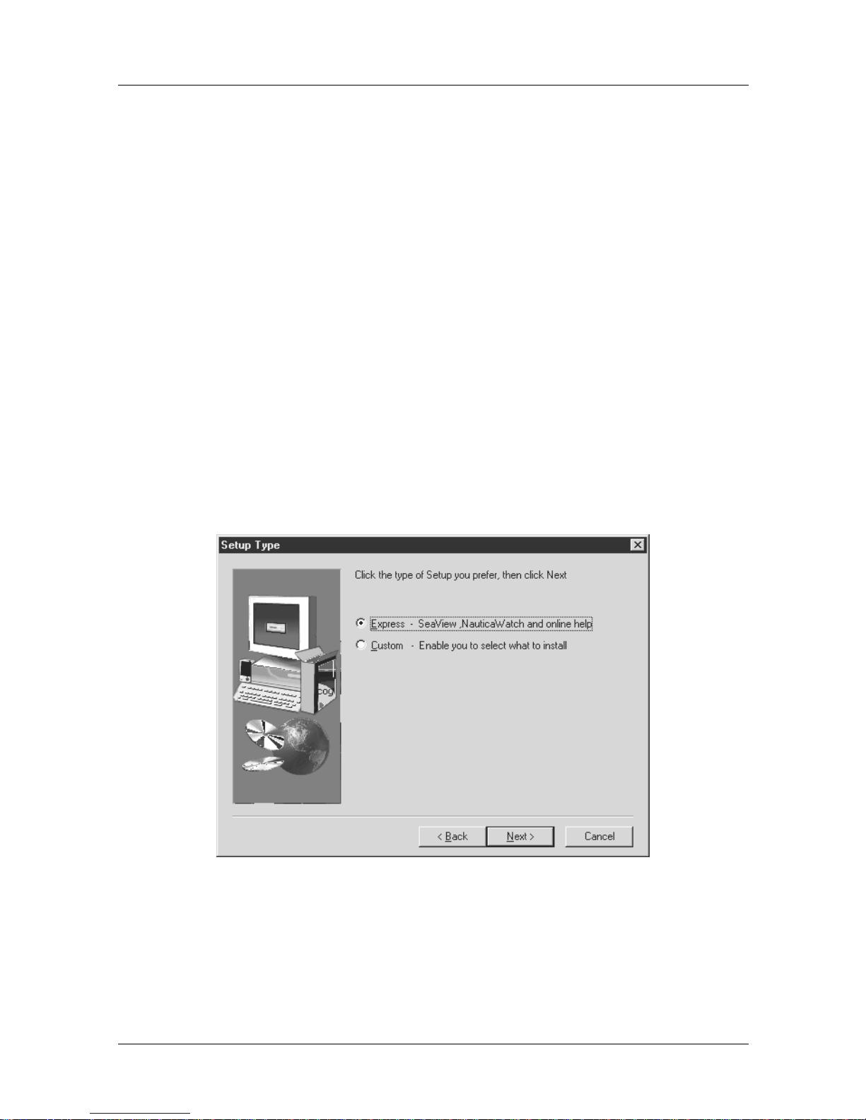
5. The Setup Type window:
Figure 1-1. Setup Type Window
You are offered two options here.
1-2 118814-A Rev. A
Page 25
Issue 1
Getting Started
• Selecting
Express
(the default) will move you directly into
the Installation Assistan t.
• Select ing the
Custom
option allows you to specify exactly
what parts of the software you want to install before
launching the Installation Assistant.
Note:
If you are a first time user of Nautica Wizard, it is
recommended that you select the Express option. Additional
software elements can be added at a later time by running the
Nautica Wizard setup program again, then clicking on the
Custom option (Figure 1-1
) and selecting the parts of the
program you want to install.
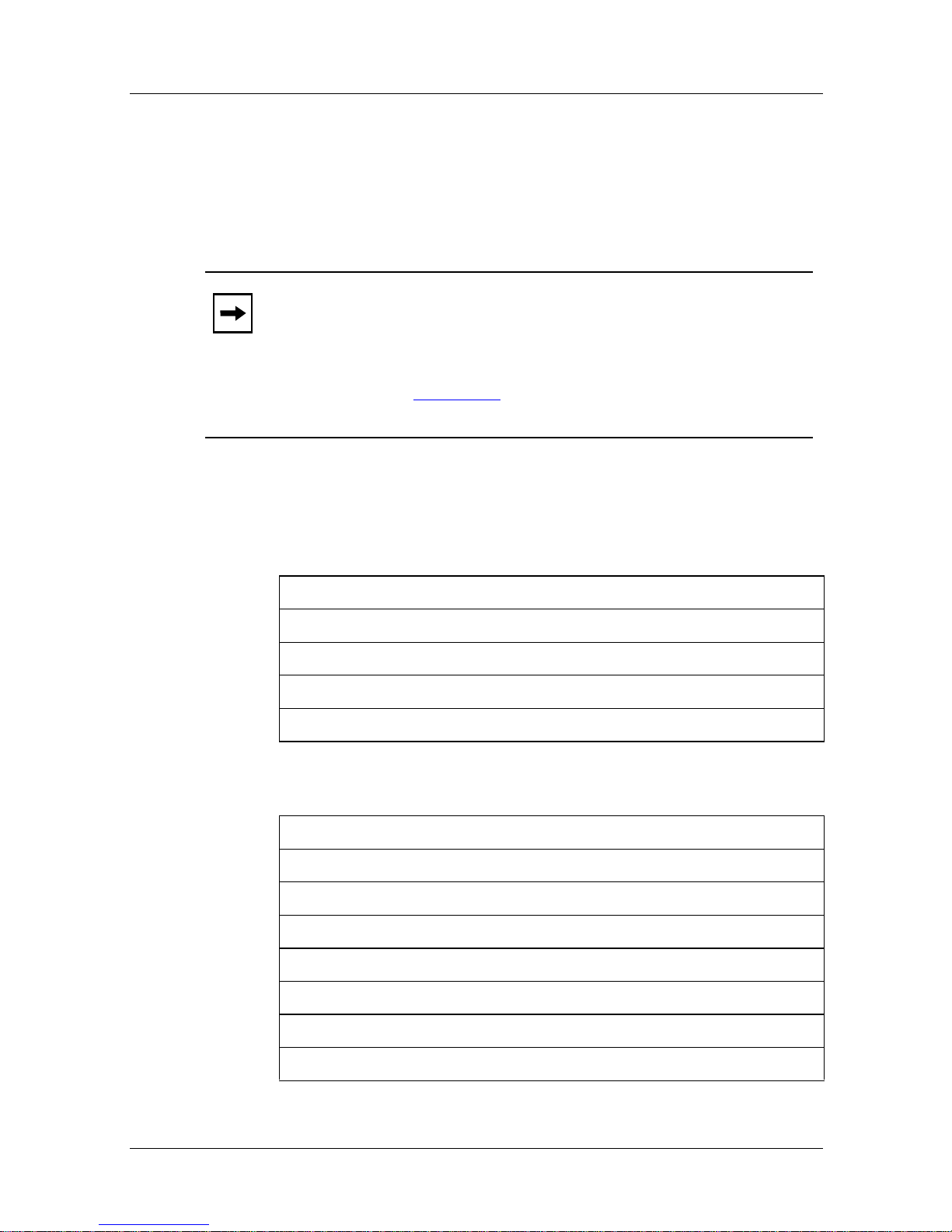
Before the Setup program launches the Installation Assistant, it is
advisable to have the following information to hand:
Table 1-1. European Interface Requirements
Your unique IP address
Your subnet mask
The name of your Nautica 200
The ISDN telephone number of the unit you want to call
Any password you have been asked to use (optional)
Table 1-2. North American Interface Requirements
Your unique IP address
Your subnet mask
The name of your Nautica 200
The ISDN telephone number of the unit you want to call
Any password you have been asked to use (optional)
The central office switch type used by your telephone company
Your local ISDN telephone number(s)
Your SPIDs
118814-A Rev. A 1-3
Page 26
Issue 1
Nautica Configuration Wizard Reference Guide
Using the Installation Assistan t
The Installation Assistant is a software program that launches
automatically when you connect a Nautica u nit to your PC for the
first time. It allows you to simply and quickly enter basic
configuration information into the unit.
At the end of the installation, the prog ram will automatically
launch Nautica Wizard. Nautica Wizard is a Windows
configur atio n tool th at allows you to configure y our Nau tica units
via Windows 95. In future, Nautica Wizard will automatically
launch the Installation Assistant every time it detects a new unit,
or a unit set to the default configuration, attached to the network.
Nautica Wizard allows you to configure any Nautica product on
your LAN, including the Nautica CLAM
TM
200
, the Nautica MarlinTM range and the Nautica 4000.
TM
family, the Nautica
A Nautica unit can be configured into one of three modes:
1. Single Host Addressing (connecting to an Internet Service
Provider)
2. Standard routing
3. Cul-de-sac routing
For more information on these modes, refer to the Concepts
section of the Help file that comes with Nautica Wizard.
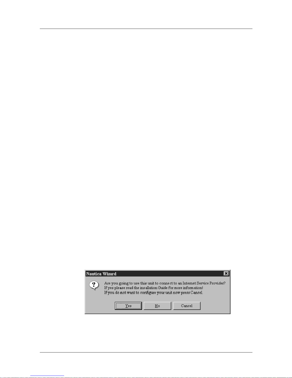
All three of these modes are config ured by following the prompts
on the screen. When the Installation Assistant starts, the
following message will appear:
Figure 1-2. ISP Connection
1-4 118814-A Rev. A
Page 27

Issue 1
Getting Started
If you answer yes to the message, you will connect to your ISP
using single host addressing. If you choose no, you will have the
option to choose Single Host Addressing at a later date, or to
either turn the unit into a standard router (refer to Chapter 3) or
into a Cul-de-sac router (refer to Chapter 4).
118814-A Rev. A 1-5
Page 28

Page 29

Chapter 2
Single Host Addressing
Single host addressing involves linking into an Internet Service
Provider (ISP). If this is what you want to do, read the
information throughout the rest of this section.
This chapter contains the following sections:
Common Errors
Required Information page 2-2
Configuration page 2-4
Switch Types page 2-6
Security page 2-6
page 2-2
118814-A Rev. A 2-1
Page 30
Issue 1
Nautica Configuration Wizard Reference Guide
Common Er rors
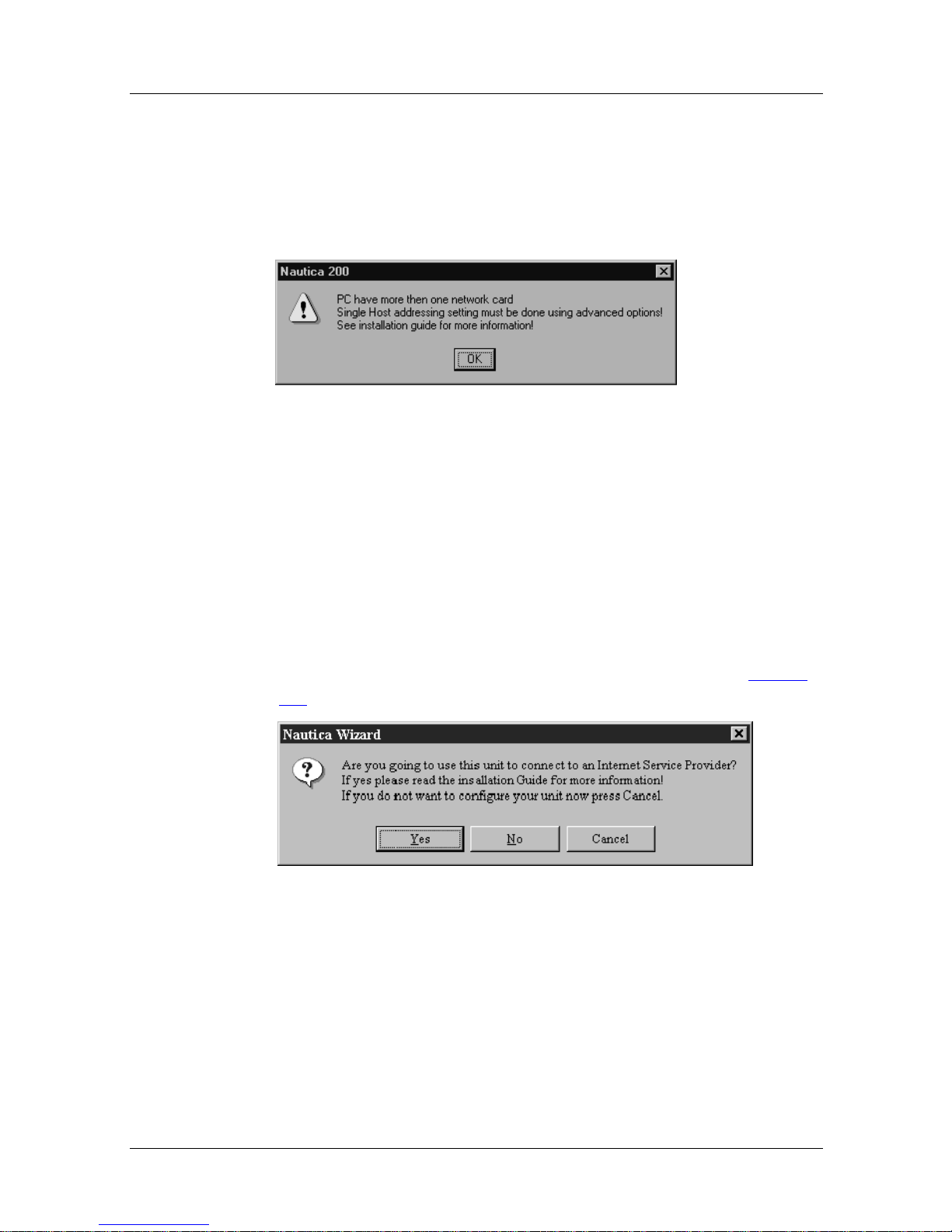
It is not possible to link a Nautica unit to an ISP if you have more
than one network adaptor on your PC. If you do have more than
one adaptor, the following error message will ap pear:
Figure 2-1. Multiple Network Interface Cards
If this message appears, refer to Chapter 5, “Troubleshooting”.
You cannot continue with the single host addressing conf igurat ion
until this error is resolved.
Setup Procedures
With one network adaptor on your PC, selecting YES in Figure
2-2 launches one of the two Welcome screens.
Figure 2-2. ISP Connection
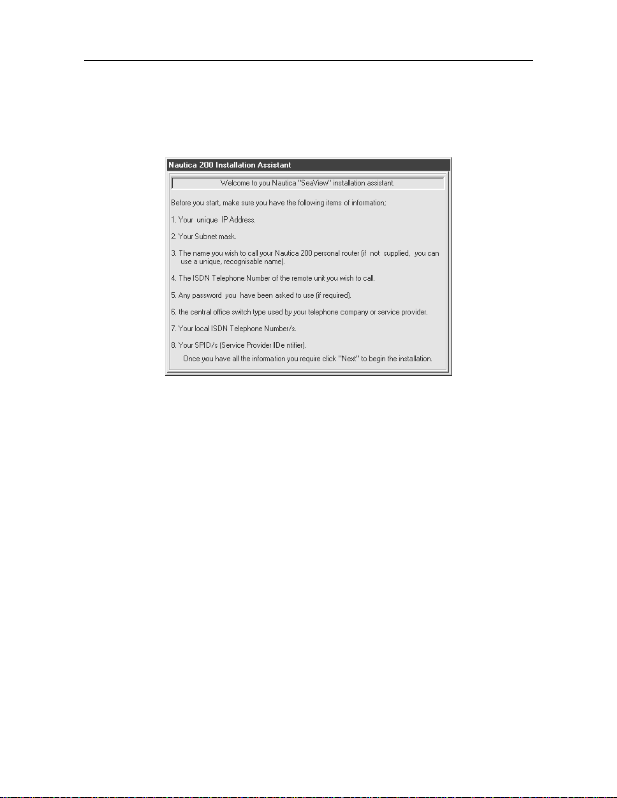
Required Information
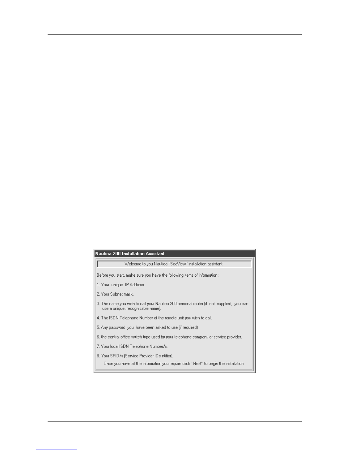
The Welcome screens list all the information you need before the
configuration can commence.
2-2 118814-A Rev. A
Page 31
Issue 1
Single Host Addressing
You will see a different screen depending on whether you are
running a European Nautica variant or a North American Nautica
variant.
Figure 2-3. North American Welcome Screen
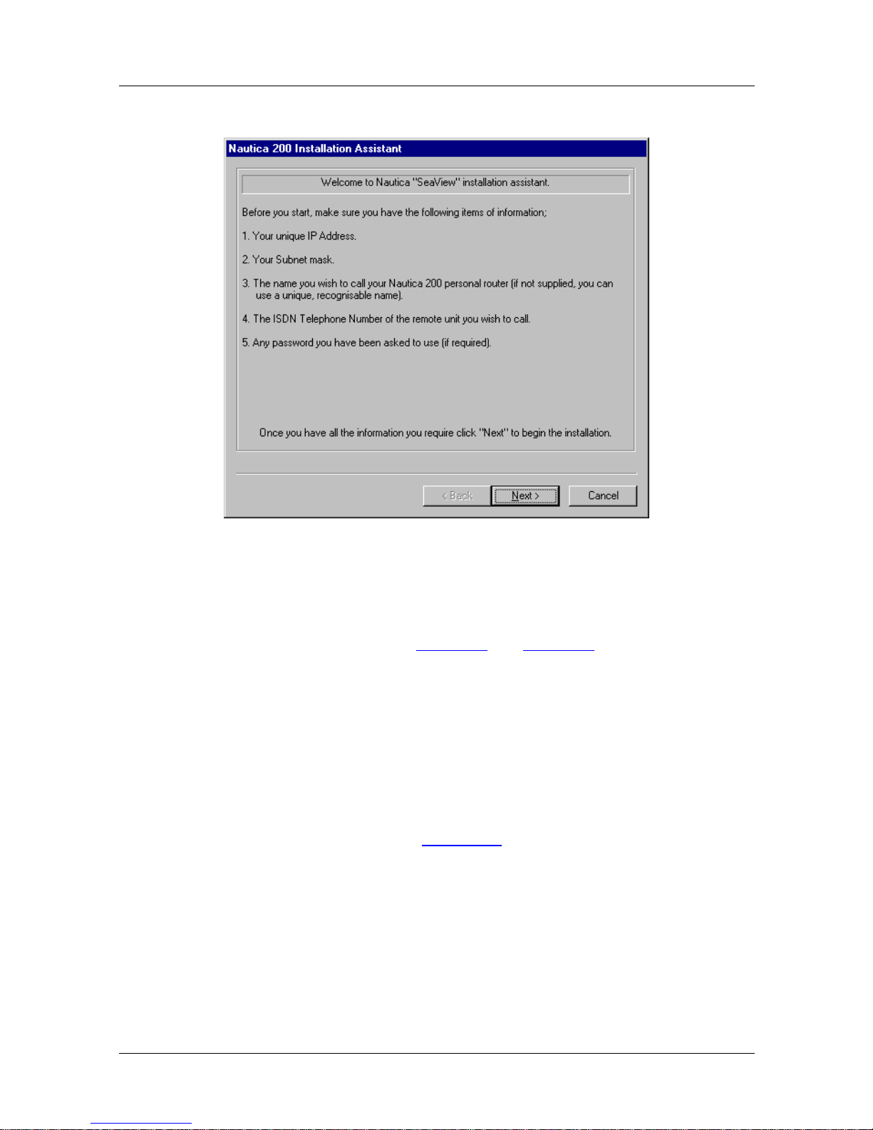
If you are using a European Nautica vari ant, the following screen
appears:
118814-A Rev. A 2-3
Page 32
Issue 1
Nautica Configuration Wizard Reference Guide
Figure 2-4. European Welcome Screen
If you do not have any of the listed data, make sure it is available
before you continue. Table 1-1
the information required for European and North American
Nautica routers.
Configuration
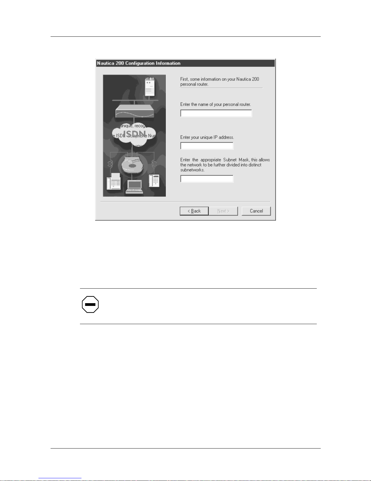
Click the Next button at the bottom of the Welcome screen to
move you into the next step of the Installation Assistant, the
configuration screen (Figure 2-5
and Table 1-2 in Chapter 1 outline
).
2-4 118814-A Rev. A
Page 33
Issue 1
Single Host Addressing
Figure 2-5. Configuration Information
You will need to enter the name of the Nautica router into this
screen. The name is the account name given to you by the ISP.
Caution:
The account name is case sensitive. Enter it exactly as
it is given to you by the ISP.
The IP address and subnet mask will be ent e red automatically
here. These items are taken from the settings in your PC. They
should match the IP address and su bnet mask given you by your
ISP. If this is no t the case, refer to Chapter 5, “Troubleshooting”,
for information on how to correct this.
118814-A Rev. A 2-5
Page 34
Issue 1
Nautica Configuration Wizard Reference Guide
Switch Types
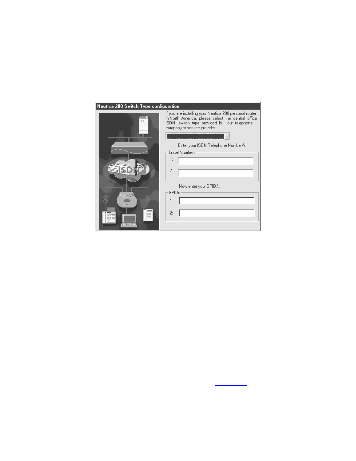
If you are based in North America, clicking the Next button will
cause Figure 2-6
to appear:
Security
Figure 2-6. Switch Type Configuration
Into this screen enter the following information:
1. Central Office ISDN switch type. This information is
provided by your ISDN supplier.
2. Local ISDN telephone numbers. This information is
provided by your ISDN supplier.
3. Any SPIDs assigned to your ISDN line. This in formation
is provided by your ISDN supplier.
Clicking Next on this screen (or on Figure 2-5 if you have a
European variant) will take you into the final window of the
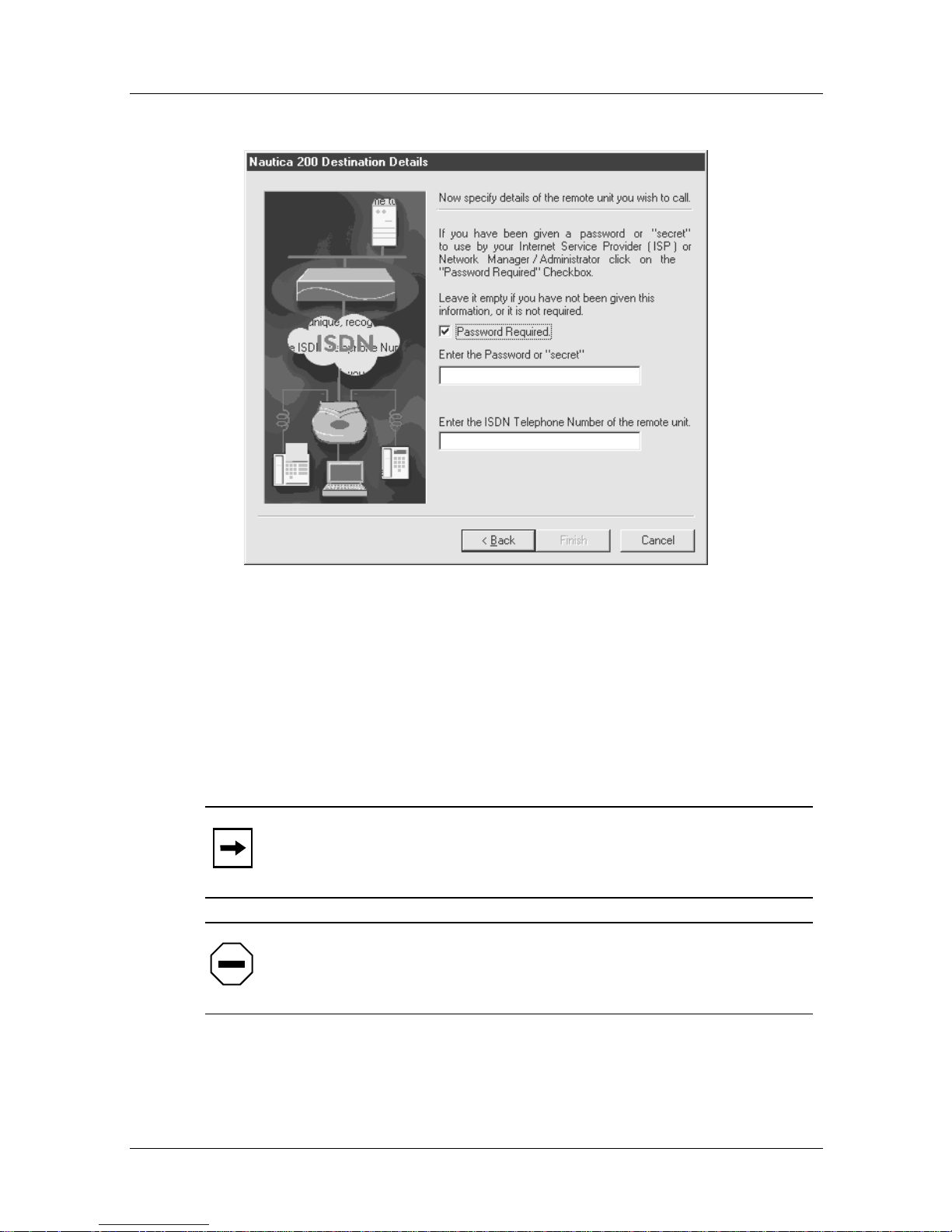
Installation Assistant, the Password window (Figure 2-7
):
2-6 118814-A Rev. A
Page 35
Issue 1
Single Host Addressing
Figure 2-7. Destination Details (Passwords)
If the ISP has prov ided you with a passwor d, enable the P asswo rd
check box and enter the password into the field that appears.
Into the next fiel d enter the ISDN t elephone number of the remo te
unit you want to connect to.
Note:
Nautica Wizard will create a path called RemotePPP to
connect to this ISDN number.
Caution:
Passwords are case sensitive. Enter the password
exactly as it is given to you by the ISP.
Click on the Finis h b utt on and the Nautica 20 0 is co nf ig ured. You
will be taken into the Nautica Wizard window.
118814-A Rev. A 2-7
Page 36

Page 37

Chapter 3
Standard Routi ng
Rather than configuring your Nautica router to connect into an
ISP (Single Host Addressing) or as a Cul-de-sac router, it is
possible to configure the unit to act as a standard router.
As a standard router, the Nautica unit you have purchased sends
and receives information from the network and then passes this
information either to another router, or to a relevan t host address.
This chapter includes the following sections:
Router Functionality
Required Information page 3-3
Configuration page 3-4
Switch Type page 3-5
Security page 3-6
page 3-2
118814-A Rev. A 3-1
Page 38
Issue 1
Nautica Configuration Wizard Reference Guide
Router Func tionality
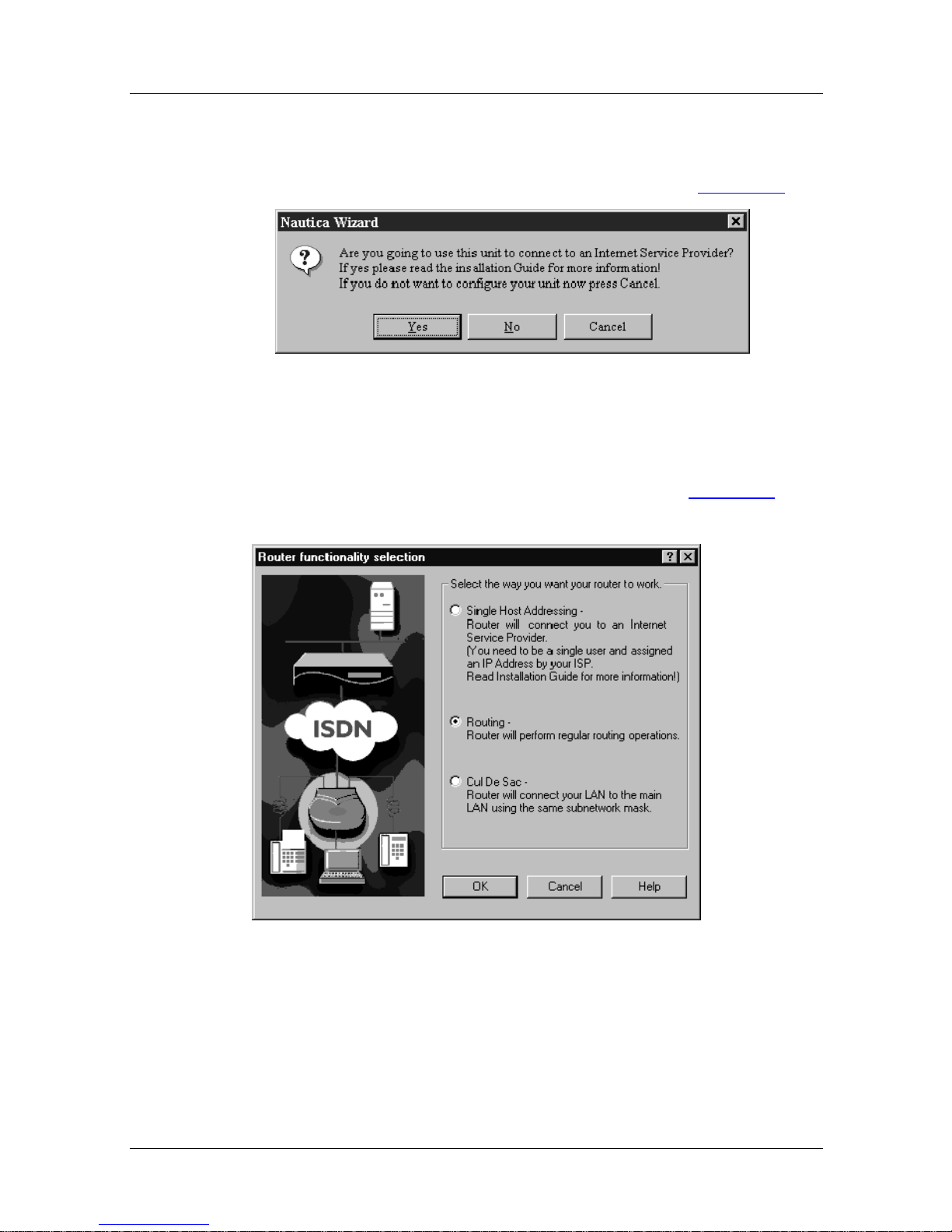
If you answer No to set up single host addressing (Figure 3-1),
Figure 3-1. ISP Connection
the Installation Assistant will launch and you will be presented
with the Router Functionality Selection window (Figure 3-2
shown here.
) as
Figure 3-2. Router Functionality Selection
There are three options you can select here.
3-2 118814-A Rev. A
Page 39
1. Single Host Addressing: If this option is selected, the router
will be setup for single host addressing. For information on
single host addressing, refer to Chapter 2.
2. Routing: This option will set the Nautica 200 as a standard
router. Read the rest of this chapter for information on how
this is done using the Installation Assistant.
3. Cul De Sac: To set the Nautica 200 as a Cul-de-sac router,
refer to Chapter 4.
Required Inf or mat ion
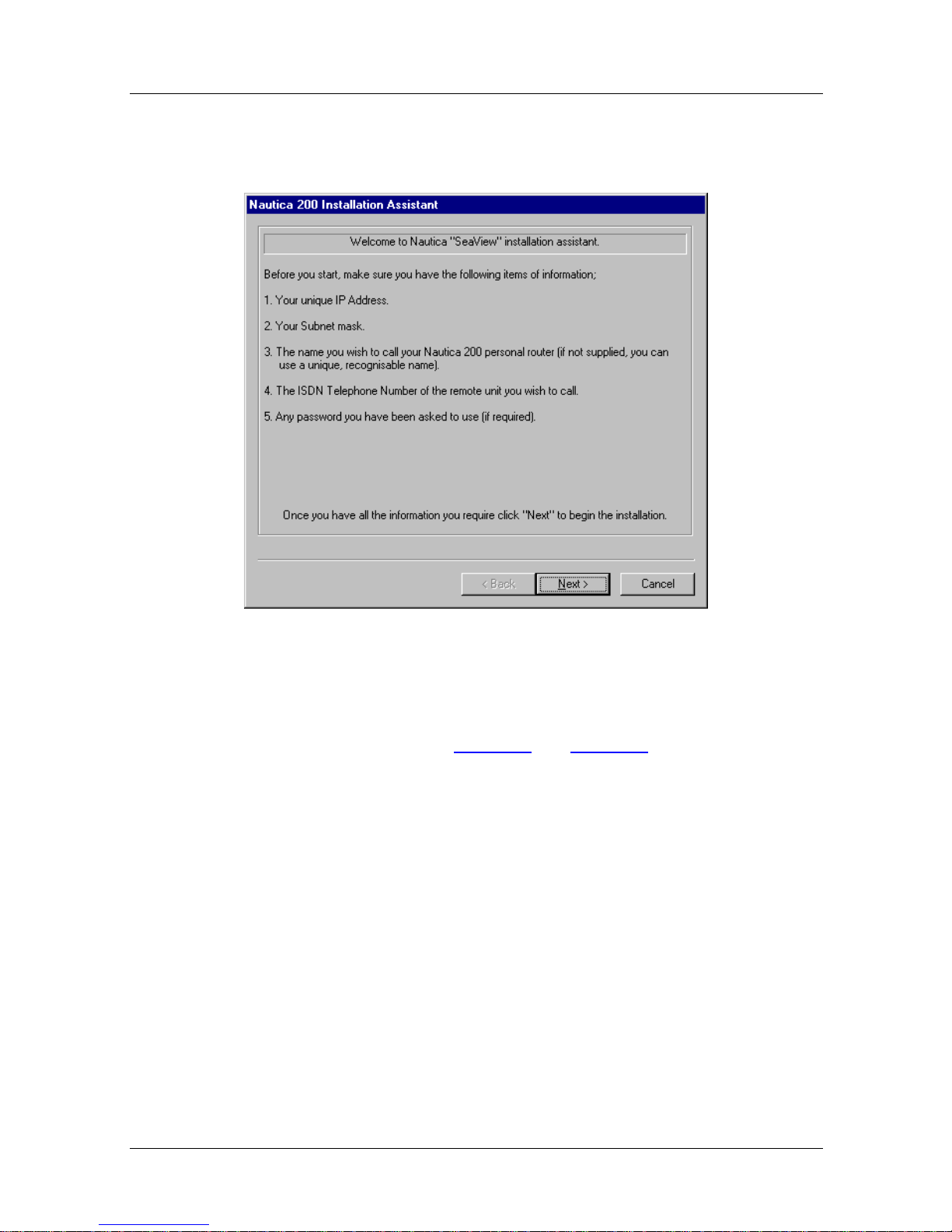
Select the Routing option and click the Next button. The
Installation Assistant will take you into the Welcome screen. the
Welcome screens list all the data required before the installation
can continue.
Issue 1
Standard Routing
Depending on whether you are using a European Nautica variant
or a North American Nautica variant, a diff erent Welcome screen
will appear. The screens are as follows:
Figure 3-3. North American Welcome Screen
118814-A Rev. A 3-3
Page 40
Issue 1
Nautica Configuration Wizard Reference Guide
For the European Nautica variant, the following screen appears:
Figure 3-4. European Welcome Screen
If you do not have any of the listed data, make sure it is available
before you continue. Table 1-1
the information required in Europe and North America.
Configuration
Click on the Next button once you have all the information and
you will be taken into the Configuration window:
and Table 1-2 in Chapter 1 outline
3-4 118814-A Rev. A
Page 41
Issue 1
Standard Routing
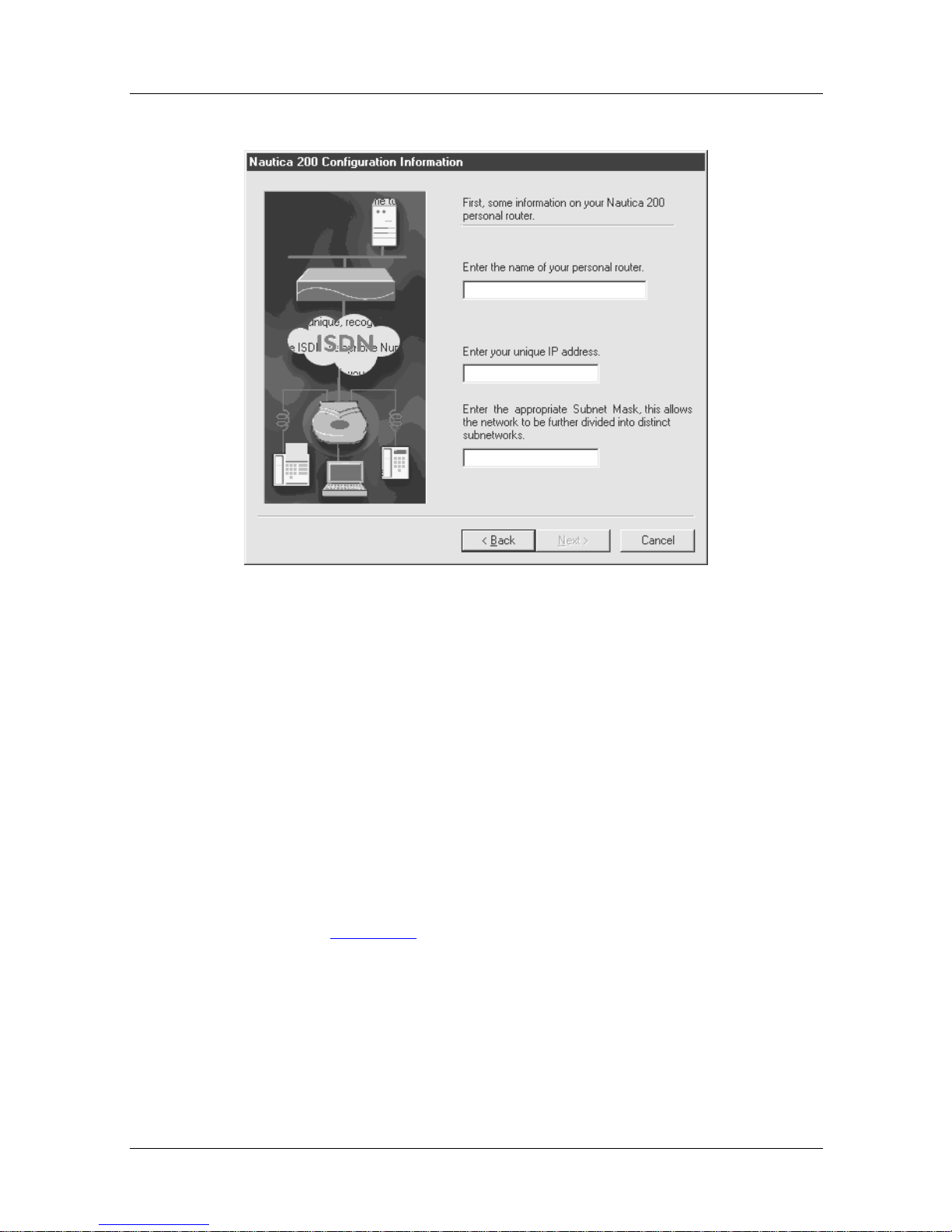
Figure 3-5. Configuration Information
Into this window enter the following information:
1. The name you want to call your Nautica 200
2. Your IP address of the format 000.000.000.000
3. The subnet mask that has been applied to your IP address
Switch Type
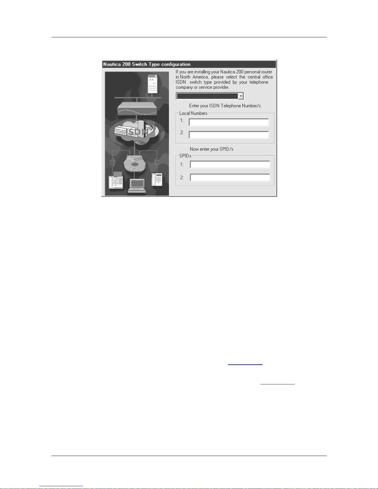
If you are based in North America, clicking the Next button will
cause Figure 3-6
to appear:
118814-A Rev. A 3-5
Page 42
Issue 1
Nautica Configuration Wizard Reference Guide
Security
Figure 3-6. Switch Type Configuration
Into this screen enter the following information:
1. Central Office ISDN switch type. This information is
provided by your ISDN supplier.
2. Local ISDN telephone numbers. This information is
provided by your ISDN supplier.
3. Any SPIDs assigned to your ISDN line. This in formation
is provided by your ISDN supplier.
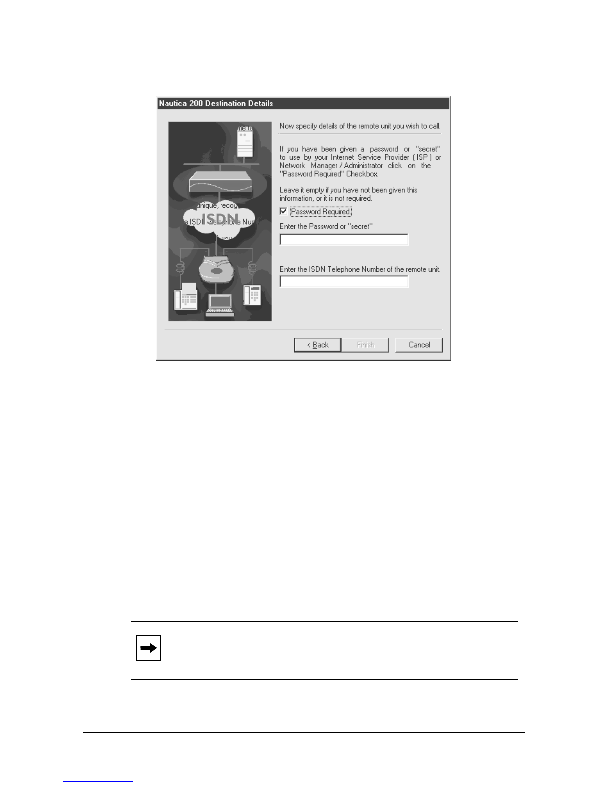
Clicking Next on this screen (or on Figure 3-5) if you are using a
European Nautica unit) will take you into the final window of the
Installation Assistant, the Password window (Figure 3-7
):
3-6 118814-A Rev. A
Page 43
Issue 1
Standard Routing
Figure 3-7. Destination Details (Passwords)
A password allows the Nautica router to be more secure.
Selecting the Password check box and enter ing a password means
that in future this password is used for all the Password
Authentication Protocol (PAP) and Challenge Handshake
Authentication Protocol (CHAP) incoming and outgoing
passwords and secrets.
For more information on setting PA P and CHAP passwords refer
to page 8-24
and page 8-25.
Into the next fiel d enter the ISDN t elephone number of the remo te
unit you want to connect to.
Note:
Nautica Wizard will create a path called RemotePPP to
connect to this ISDN number.
118814-A Rev. A 3-7
Page 44

Issue 1
Nautica Configuration Wizard Reference Guide
Caution:
The password is case sensitive, ensure you enter it
correctly.
Click on the Finis h b utt on and the Nautica 20 0 is co nf ig ured. You
will be taken into the Nautica Wizard window. For more
information on Nautica Wizard, please refer to Chapter 6.
3-8 118814-A Rev. A
Page 45

Chapter 4
Cul-de-sac Routing
Cul-de-sac routing allows you to connect a small network into a
main network, even though both networks share the same IP
addresses. This situation (also referred to as a stub network)
occurs when a small office location needs to be linked into a main
office and there are not enough IP addresses to go around.
This chapter includes the following sections:
Router Functionality
Required Information page 4-3
Configuration page 4-4
Switch Type page 4-5
Cul-de-sac Route Setup page 4-6
Security page 4-8
page 4-2
118814-A Rev. A 4-1
Page 46
Issue 1
Nautica Configuration Wizard Reference Guide
Router Func tionality
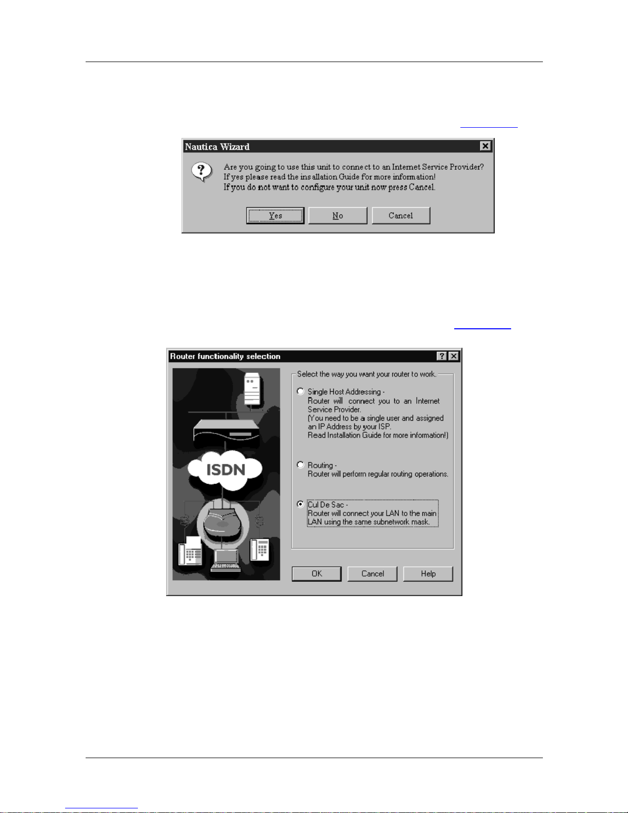
If you answer No to set up single host addressing (Figure 4-1),
Figure 4-1. ISP Connection
the Installation Assistant will launch and you will be presented
with the Router Functionality Selection window (Figure 4-2
):
Figure 4-2. Router Functionality Selection
There are three options you can select here.
1. Single Host Addressing: If this option is selected, the router
will be setup with single host addressing. For more
information on Single Host addres sing, refer to Chapter 2.
4-2 118814-A Rev. A
Page 47
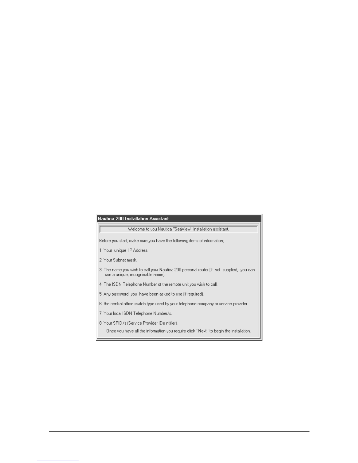
2. Routing: To set the Nautica unit as a standard router, refer to
Chapter 3.
3. Cul De Sac: To set the Nautica unit as a Cul-de-sac router,
read the rest of this chapter.
Required Inf or mat ion
Select the Cul De Sac option and click the Next button. The
Installation Assistant will take you into the Welcome screen. The
Welcome screens contain all the information required before the
installation can continue.
Depending on whether you are using a European Nautica router
or a North American Nautica router, a different Welcome screen
will appear. The screens are as follows:
Issue 1
Cul-de-sac Routing
Figure 4-3. North American Welcome Screen
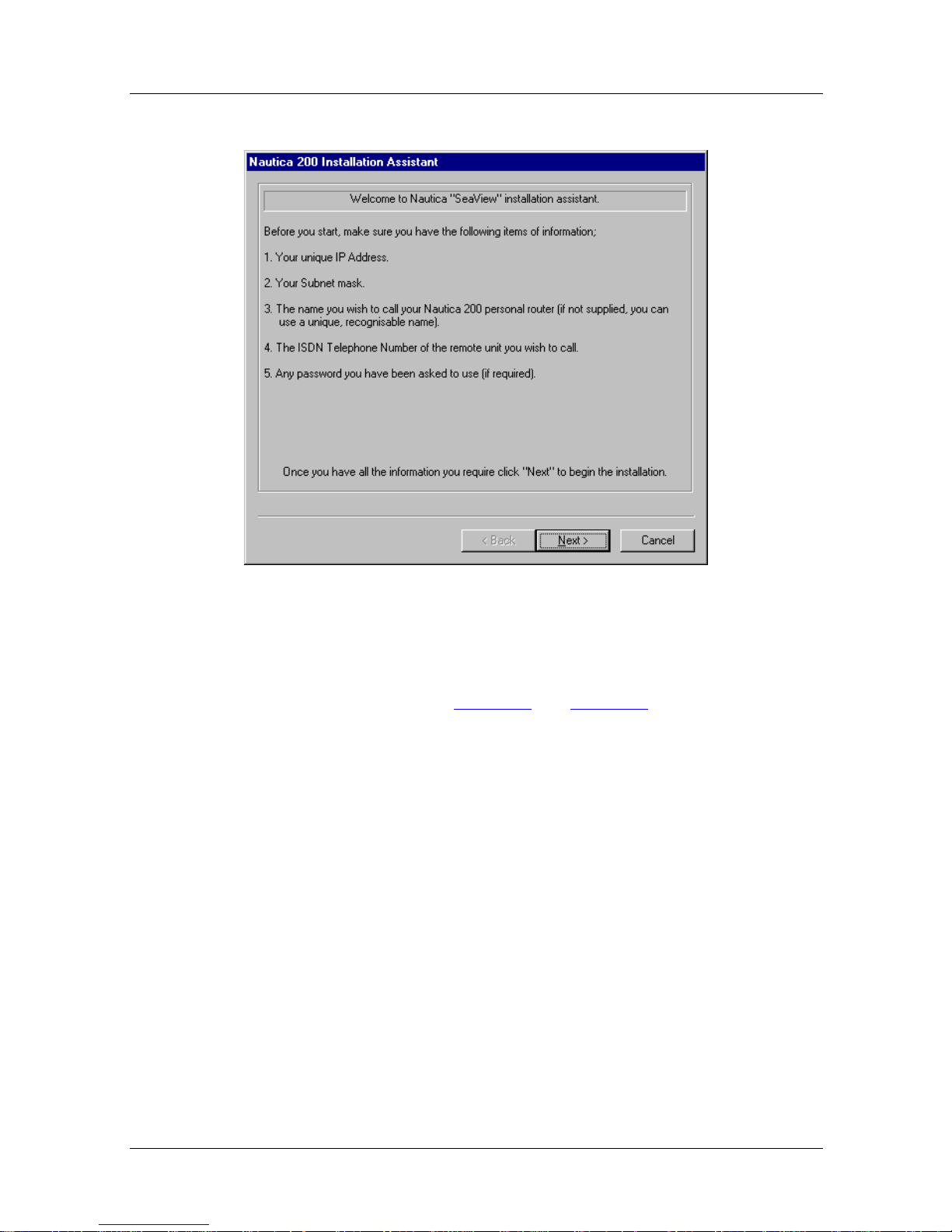
If you are using a European Nautica router, the following screen
appears:
118814-A Rev. A 4-3
Page 48
Issue 1
Nautica Configuration Wizard Reference Guide
Figure 4-4. European Welcome Screen
If you do not have any of the listed data, make sure it is available
before you continue. Table 1-1
the information required in Europe and North America.
Configuration
Click on the Next button once you have all the information and
you will be taken into the Configuration window:
and Table 1-2 in Chapter 1 outline
4-4 118814-A Rev. A
Page 49
Issue 1
Cul-de-sac Routing
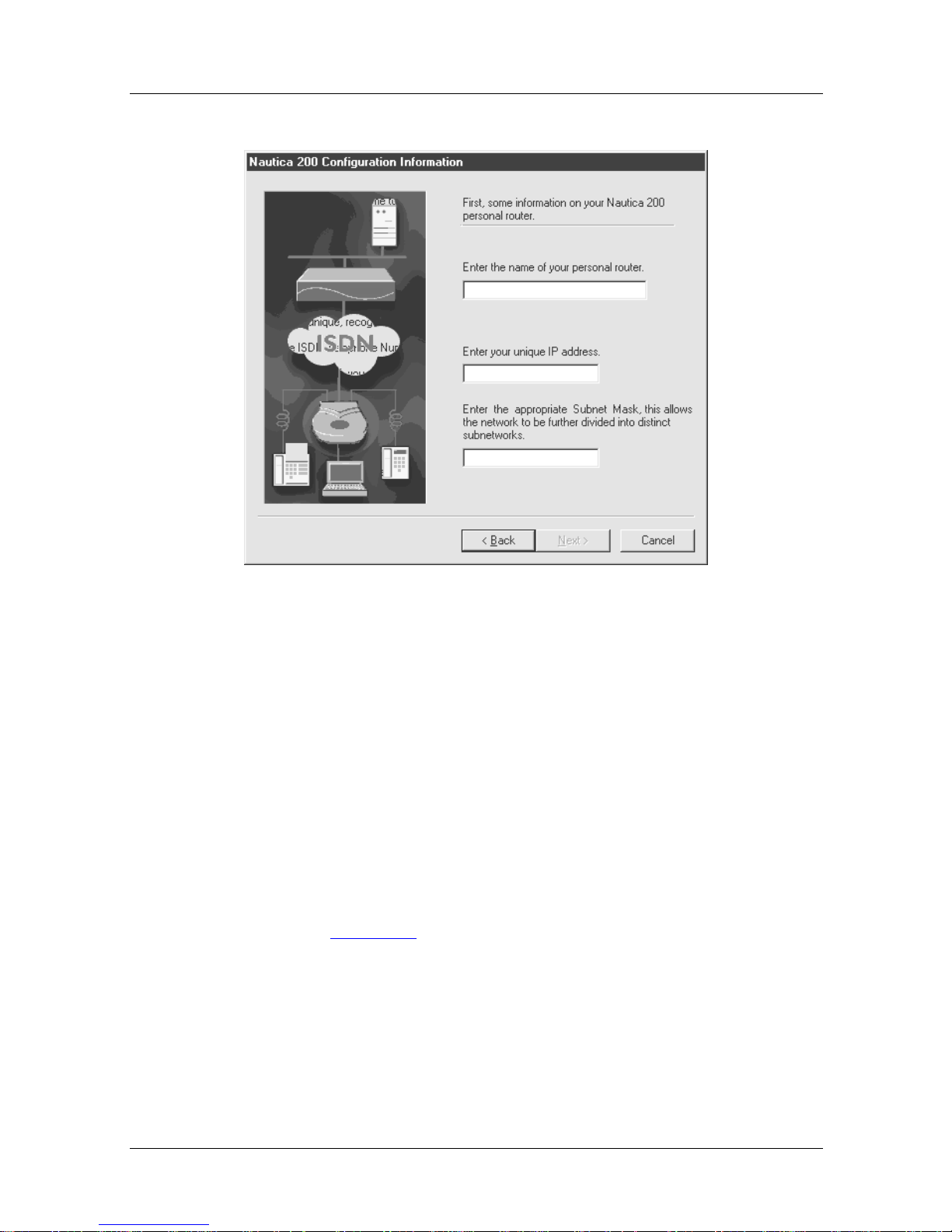
Figure 4-5. Configuration Information
Into this window enter the following information:
1. The name you want to call your Nautica router
2. Your IP address of the format 000.000.000.000
3. The subnet mask that has been applied to your IP address
Switch Type
If you are based in North America, clicking the Next button will
cause Figure 4-6
to appear:
118814-A Rev. A 4-5
Page 50
Issue 1
Nautica Configuration Wizard Reference Guide
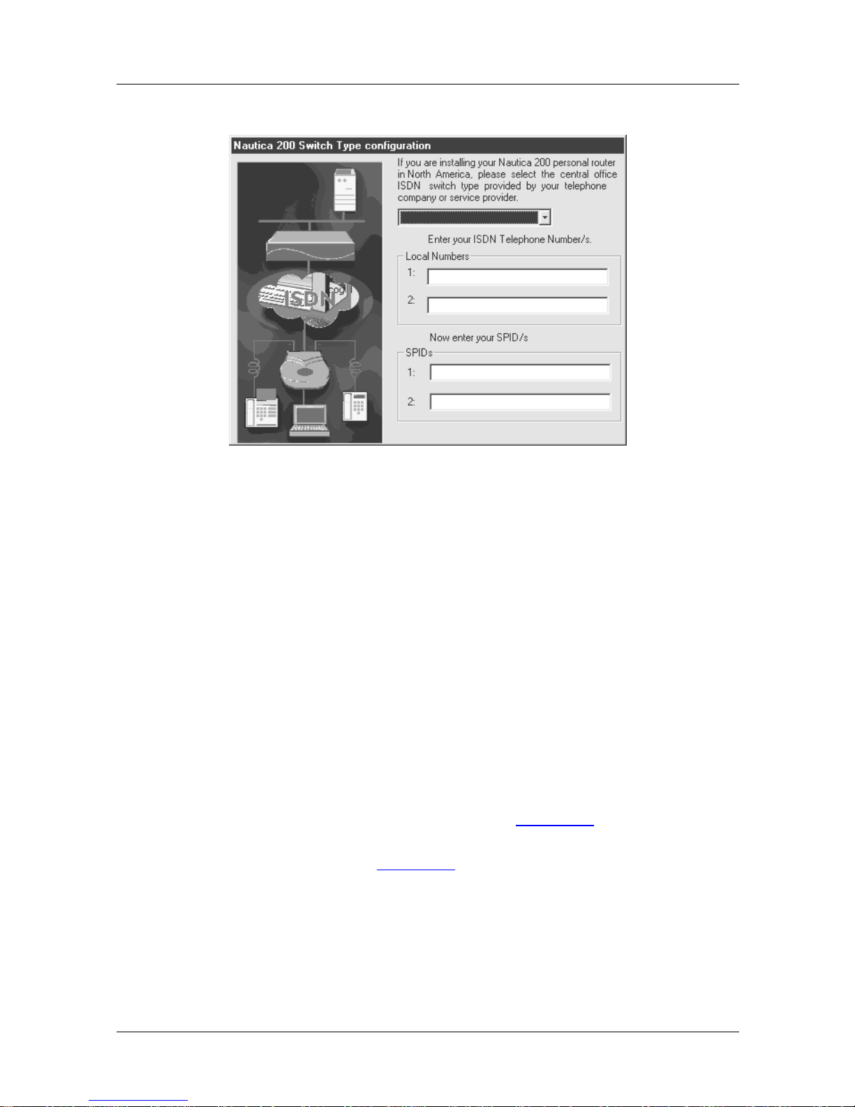
Figure 4-6. Switch Type Configuration
Into this screen enter the following information:
1. Central Office ISDN switch type. This information is
provided by your ISDN supplier.
2. Local ISDN telephone numbers. This information is
provided by your ISDN supplier.
3. Any SPIDs assigned to your ISDN line. This in formation
is provided by your ISDN supplier.
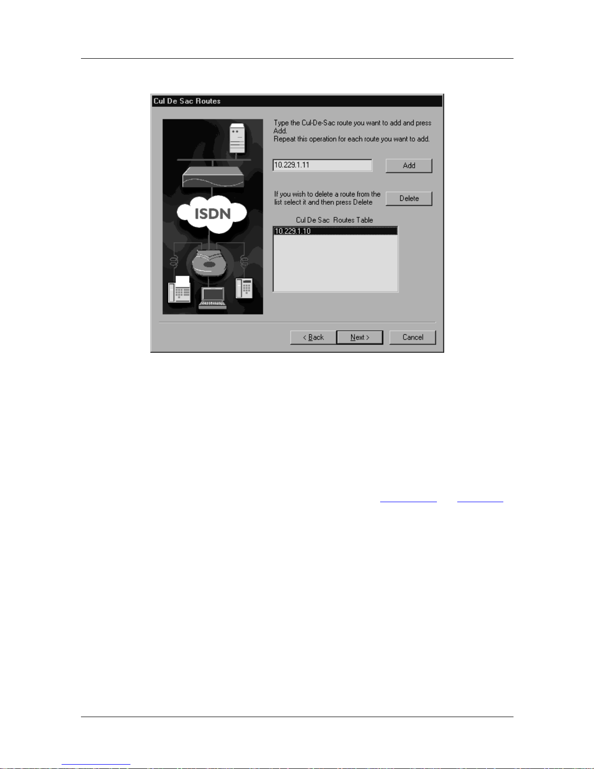
Cul-de-sac Route Setup
Clicking Next on this screen (or on Figure 4-5) if you are using a
European Nautica router) will take you into the Cul-de-sac
Routes window (Figure 4-7
):
4-6 118814-A Rev. A
Page 51
Issue 1
Cul-de-sac Routing
Figure 4-7. Cul-De-Sac Routes Window
Into this screen enter the following information:
1. Specify the IP addresses of the Cul-de-sac routes you
want to add. Once done, click on the Next button.
2. You will move into the last Installation Ass istant screen
(Destination Details) as shown in Figure 4-8
on page 4-8.
Please refer to this page for the rest of the information on
the Nautica Wizard Installation Assistant.
118814-A Rev. A 4-7
Page 52
Issue 1
Nautica Configuration Wizard Reference Guide
Security
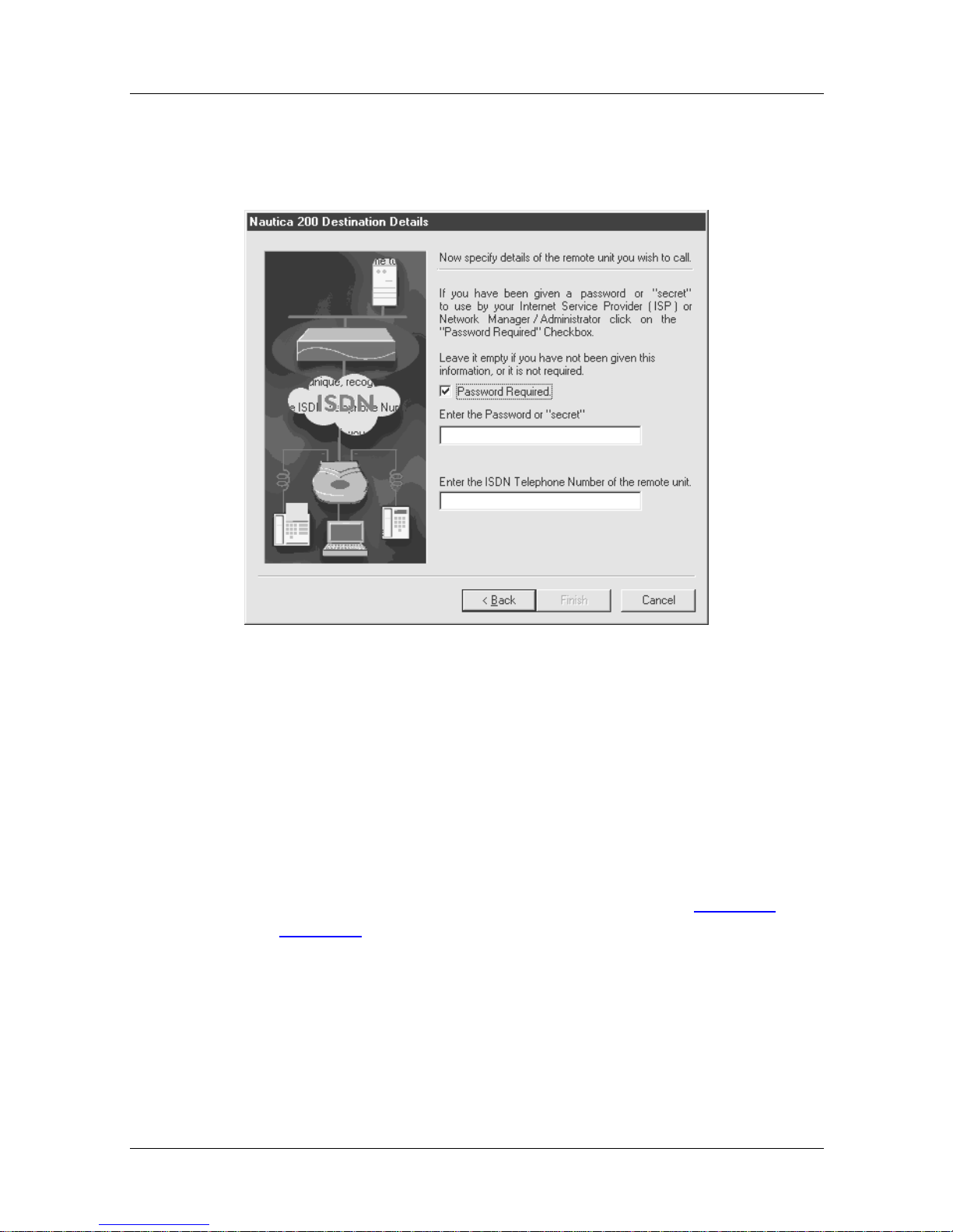
Figure 4-8. Destination Details (Passwords)
A password allows the Nautica router to be more secure.
Selecting the Password check box and enter ing a password means
that in future this password is used for all the Password
Authentication Protocol (PAP) and Challenge Handshake
Authentication Protocol (CHAP) incoming and outgoing
passwords and secrets.
For more information on PAP and CHAP, refer to page 8-24
page 8-25
.
and
4-8 118814-A Rev. A
Page 53

Issue 1
Cul-de-sac Routing
Into the next fiel d enter the ISDN t elephone number of the remo te
unit you want to connect to.
Note:
Nautica Wizard will create a path called RemotePPP to
connect to this ISDN number.
Caution:
The password option is case sensiti ve. Make sur e you
enter the password correctly.
Click on the Finish button and the Nautica router is configured.
You will be taken into the Nautica Wizard window. For more
information on Nautica Wizard, refer to Chapter 6.
118814-A Rev. A 4-9
Page 54

Page 55

Chapter 5
Troubleshooting
This chapter deals with the three most common problems you will
encounter when installing and configuring your Nautica unit
using Nautica Wizard and the Installation Assistant.
The chapter contains the followi ng sections:
Multiple Network Adaptors
Incorrect PC IP Address page 5-5
Configuration Communication Error page 5-8
page 5-2
118814-A Rev. A 5-1
Page 56
Issue 1
Nautica Configuration Wizard Reference Guide
Multiple Network Adaptors
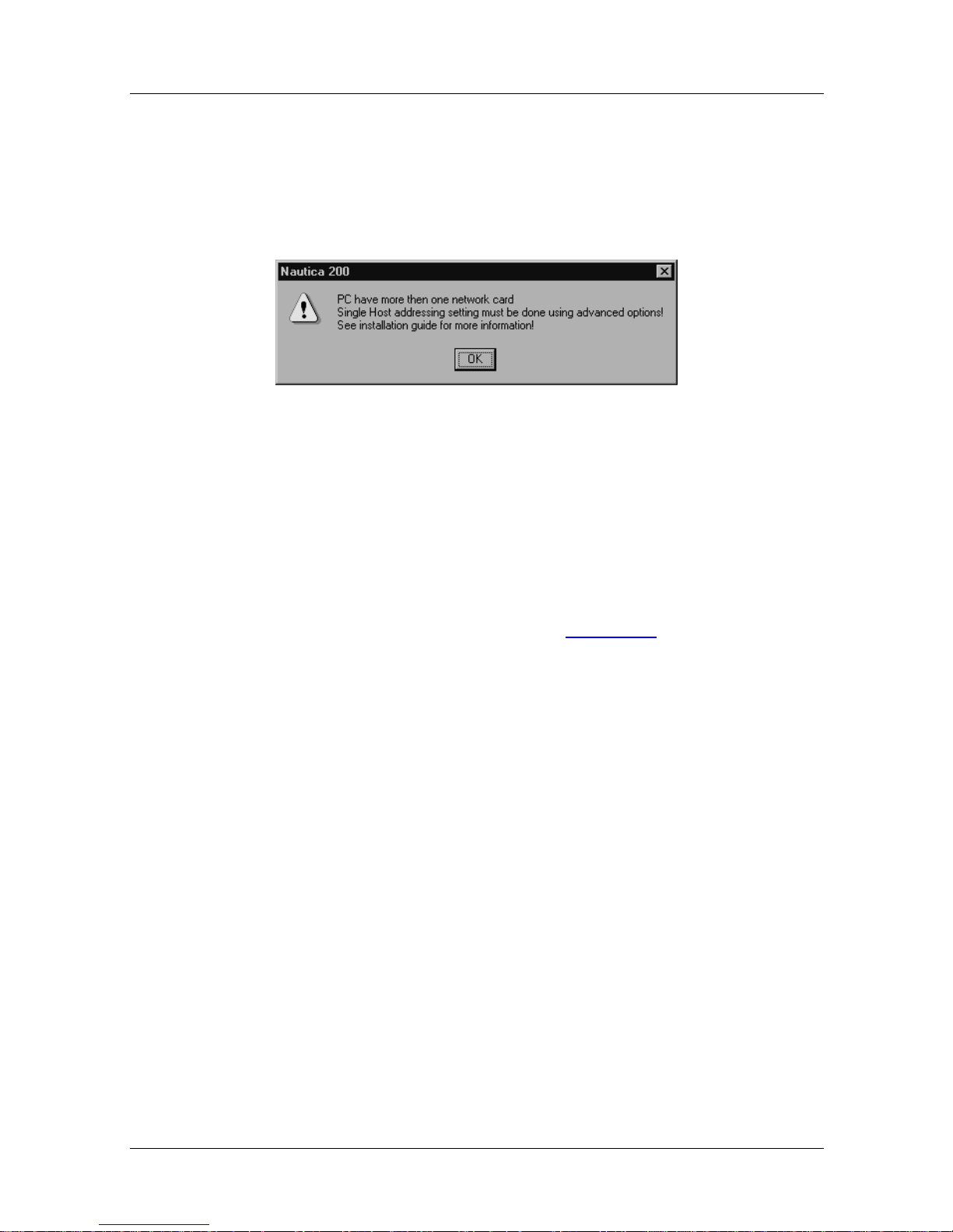
If you use the Installation Assistant to set up the Nautica router as
a single host addressing router, you may see the following error
message:
Figure 5-1. Multiple Network Adaptor Error
You will not be able to proceed with the installation until this
error is rectified.
1. Cancel out of the Installation Assistant.
2. In Windows 95, click on Start > Settings > Control Panel.
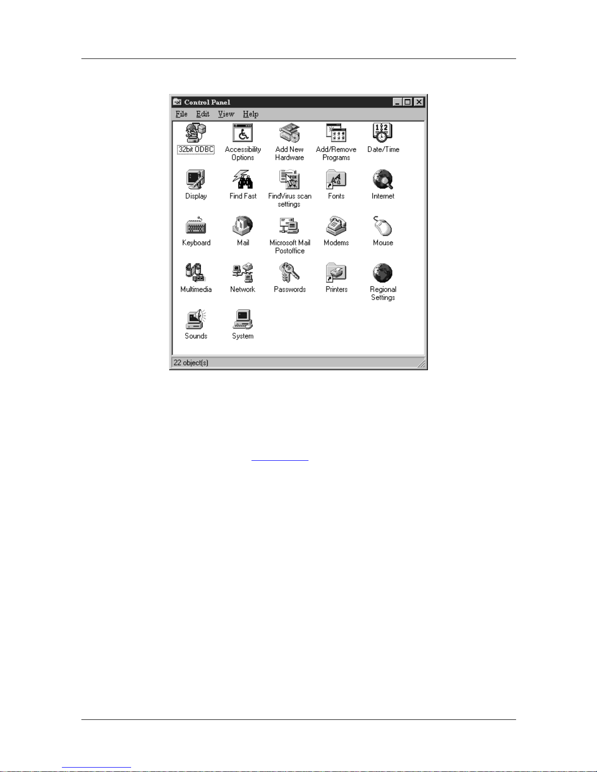
3. The Control Panel window (Figure 5-2
) will appear:
5-2 118814-A Rev. A
Page 57
Issue 1
Troubleshooting
Figure 5-2. Windows 95 Control Panel
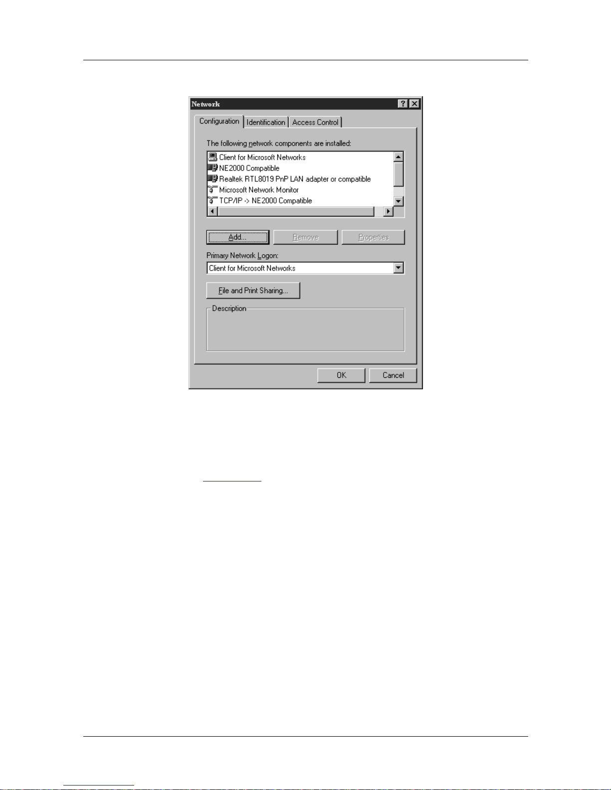
4. Double click the network icon to open the Network
window. (Figure 5-3
)
118814-A Rev. A 5-3
Page 58
Issue 1
Nautica Configuration Wizard Reference Guide
Figure 5-3. Windows 95 Network window
5. Leave the first network adaptor (NE2000 compatible in
Figure 5-3
), but select all the other adaptors you have
listed (they will all have the PC Card icon) and click on
the Remove button.
6. Click on OK to close the Network window and close down
the Control Panel.
7. Launch Nautica Wizard by double clicking its icon on the
desktop (or opening it from the Program menu).
8. Nautica Wizard will attach to the Nautica unit and start
the Installatio n Assistant automatically.
9. Return to Chapter 2.
5-4 118814-A Rev. A
Page 59
Incorrect PC IP Address
If, when you are setting the Nautica router as a single host
addressing router, you notice that the IP address entered into
Figure 2-5
you by the ISP, you need to change the PC IP address to match the
number supplied by the ISP.
Continue with the Installation Wizard and close Nautica Wizard
down once it has finished.
To correct the PC IP address, do the following:
1. In Windows 95, click on Start > Settings > Control Panel.
on page 2-5 is different than the IP address given to
Issue 1
Troubleshooting
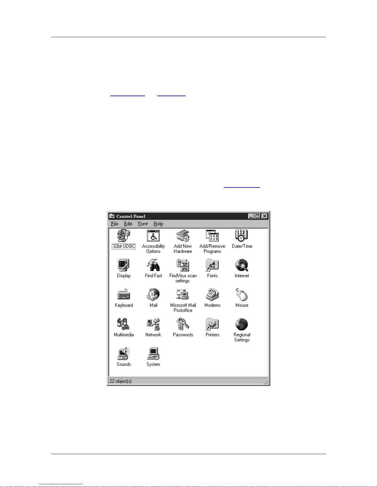
2. The Control Panel window (Figure 5-4
) will appear:
Figure 5-4. Windows 95 Control Panel
118814-A Rev. A 5-5
Page 60
Issue 1
Nautica Configuration Wizard Reference Guide
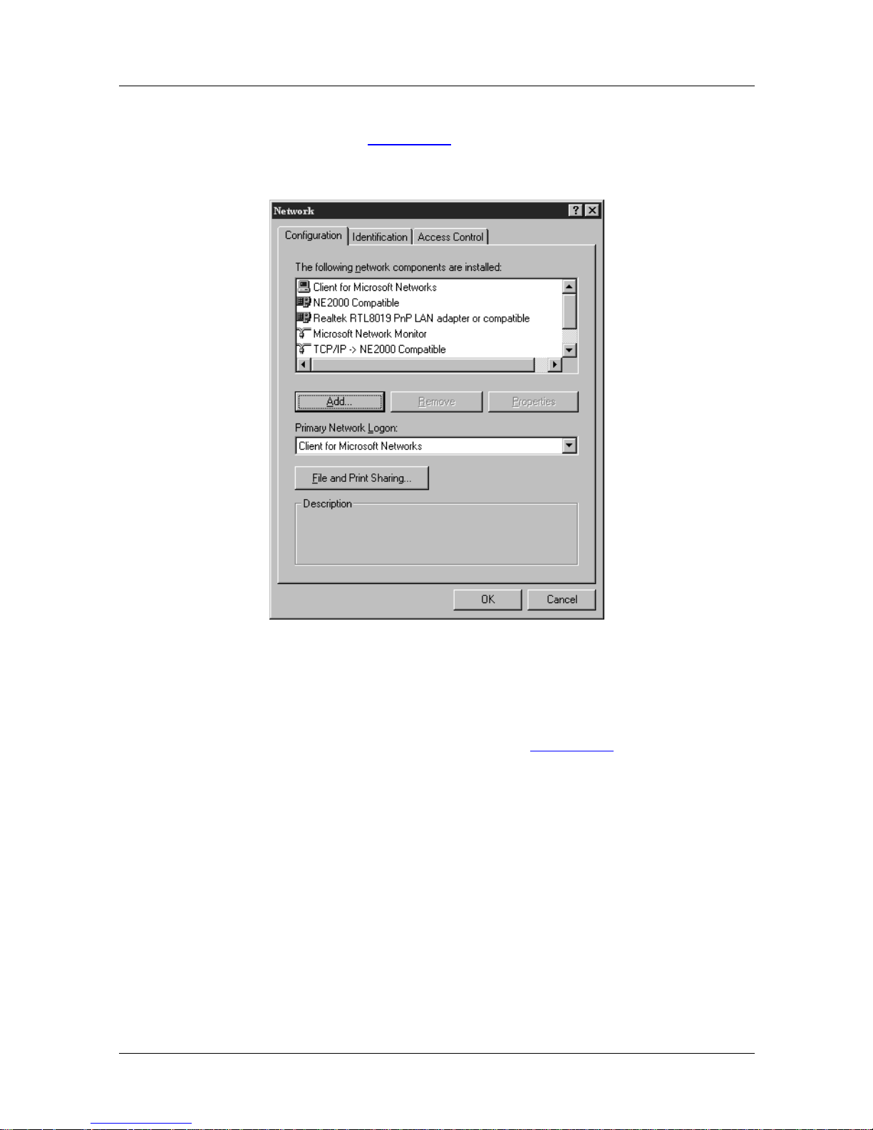
3. Double click the network icon to open the Network
window. (Figure 5-5
)
Figure 5-5. Windows 95 Network window
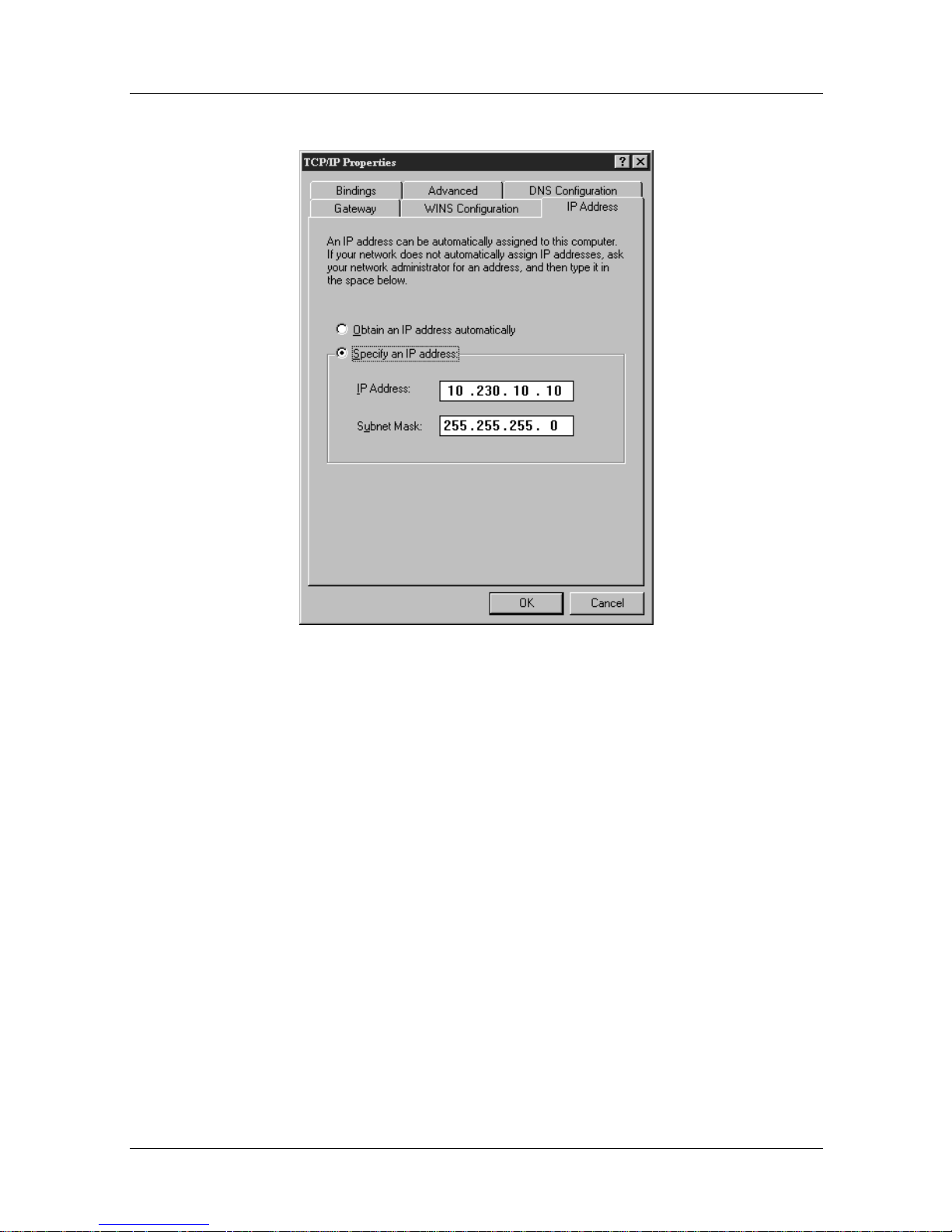
4. Select the TCP/IP adaptor and click on the Properties
button. The TCP/IP window (Figure 5-6
5-6 118814-A Rev. A
) appears.
Page 61
Issue 1
Troubleshooting
Figure 5-6. Windows 95 TCP/IP Properties
5. Into this window, enter the correct IP address and subnet
mask as provided by the ISP. Click on OK to close the
TCP/IP Properties window.
6. Click on OK to close the Network window and close down
the Control Panel.
7. Launch Nautica Wizard by double clicking its icon on the
desktop (or opening it from the Program menu).
8. Nautica Wizard will attach to the Nautica router and will
automatically pick up the new IP address and mask.
118814-A Rev. A 5-7
Page 62
Issue 1
Nautica Configuration Wizard Reference Guide
Configuration Communication Error
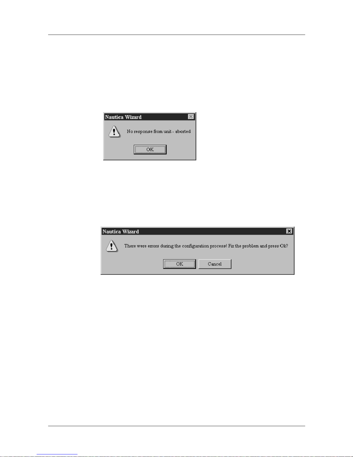
Occasionally, when you click on the Finish button in the last
screen of the Installation Assistant, th e following window
appears:
Figure 5-7. Connection Error
Click on OK. The following screen appears:
Figure 5-8. Configuration Error
If these screens appear, it means that the PC cannot communicate
with the Nautica router. Nautica W izard will attempt to rectify the
situation. If it fails, ensure that all the cables are connected as per
the instructions in the Installa tion manual.
Click on OK in this second window. The Installation Assistant
will re-send all the information you have entered to the unit again.
If problems persist, consult the supplier of yo ur equipment.
5-8 118814-A Rev. A
Page 63

Chapter 6
Basic Procedures
Nautica Wizard allows you to configure your Nautica units
simply and efficiently. More advanced router users may prefer to
configure their units using Nautica Router Software Release 4
(BCC).
If you would like to use the Release 4 software, refer to the
Nautica Router Software Release 4 documentation on the CD that
comes with your Nautica product.
This chapter contains the following sections:
Important - Please Read
Initial Operations page 6-6
The Nautica Wizard Window page 6-6
Basic Nautica Wizard Operations page 6-11
page 6-2
118814-A Rev. A 6-1
Page 64

Issue 1
Nautica Configuration Wizard Reference Guide
Important - Please Read
Use of an ISDN router over a public ISDN network are usually on
a pay-as-you-go basis. You pay for the time that your ISDN link
is connected, although some suppliers also charge for every call
attempt.
Your ISDN router makes calls when there is one or more packets
to send to a remote network. In order to reduce the amount of
ISDN calls this can generate, it is important that you read the rest
of this section. The options outlined here can dramatically reduce
the amount of automatic ISDN calls made by your router.
Your Nautica router comes with a software package called
Nautica Watch (Chapter 15). Nautica Watch allows you to
monitor the activity on your router. The LED on the front of the
router also shows when the router is in use. The green LED will
flash continuously when the router is in use. If this happens when
you are not actively using your PC, then the PC or an application
on the PC is connecting to a remote network resour ce.
If you are in any doubt at all about any of the following points, or
the operation of your router, contact your local ISDN supplier for
advice.
E-mail Clients
Most TCP/IP based e-mail clients can be configured to check the
mail server for new mail at set intervals. This is known as polling.
If you are locally attached to a mail server, it may be appropriate
to poll for e-mail every fi ve minutes or less. These rules change if
you are remotely connected to a mail server via an ISDN router. It
is not appropriate, for example, to have the router calling the
remote mail server every five minutes to check for new mail.
6-2 118814-A Rev. A
Page 65

To this end, it is recommend e d that you configure your e-mail
client for manual polling (where you press a button to check for
e-mail), or for a longer polling interval, such as once every hour.
Be aware though, that even with an hourly polling setting, the
router will make one call every hour. If you leave your PC and
router running overnight, this wo uld mean 24 calls every day,
even if you have no new e-mail.
Remotely Mapped Drives
In most popular PC operating systems, it is possible to map
virtual drives (such as J:) to file servers on the network. If you
map network drives over a remote ISDN connection, problems
can occur.
Issue 1
Basic Procedures
Every time you open a file, or move into a new folder, it is like ly
that the PC may request the current status of all drives and bring
up an ISDN call to achieve this.
For this reason, it is recommended that you do not permanently
map network drives over a remote ISDN connection.
Similarly, if you browse the Network Neighborhood over a
remote ISDN connection you will incur ISDN call charges.
File and Print Sharing
Many workgroup functions, designed to allow resource sharing
on a local network, use a periodic announcement/update
mechanism which causes frequent ISDN calls if used over a
remote ISDN connection. In order to avoid this, it is
recommended that you turn off file and print sharing on your PC.
To achieve this, do the following:
1. Click on the Start Button.
2. Choose Settings > Control Panel.
3. Double click on the Networks icon.
4. Click on the File and Print Sharing button.
118814-A Rev. A 6-3
Page 66
Issue 1
Nautica Configuration Wizard Reference Guide
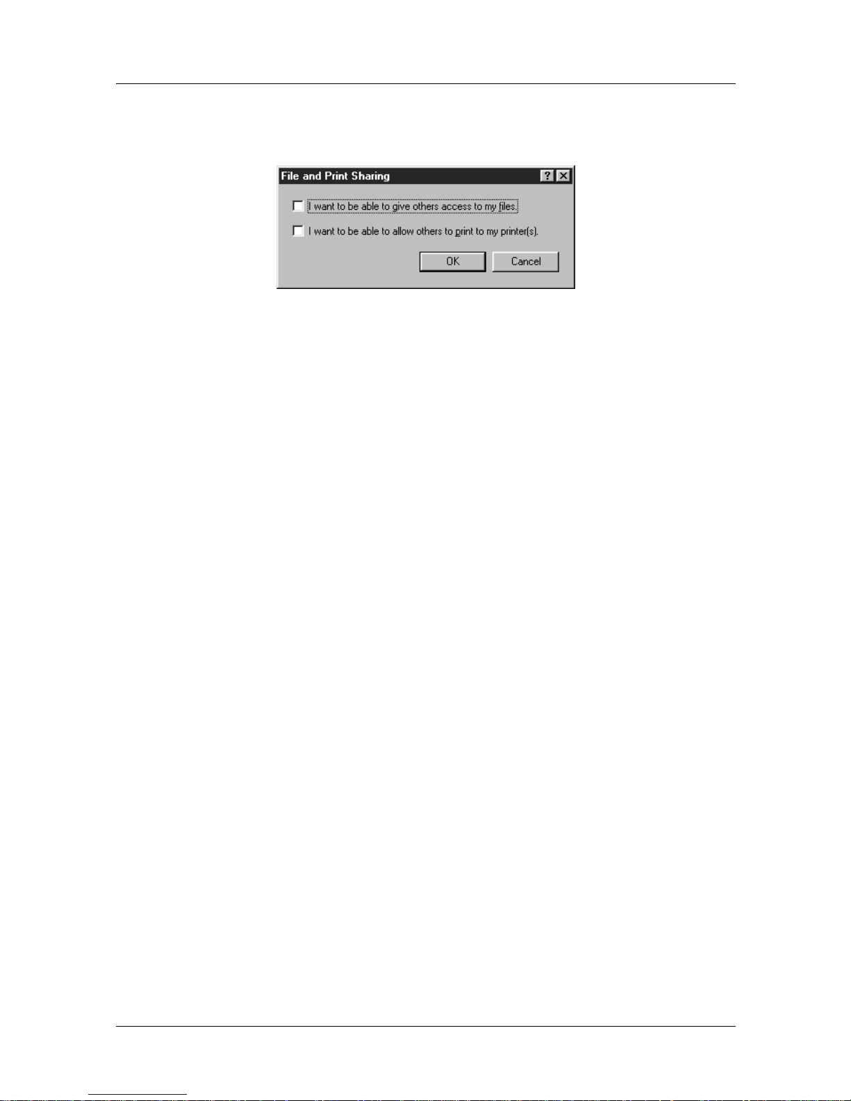
5. Deselect both options in the File and Print Sharing
window:
Figure 6-1. File and Print Sharing Window
6. Click on the OK button in the File and Print Sharing
window.
7. Click on OK in the Networks window.
8. Close down the Control Panel.
9. It may be necessary to reboot your PC at this time.
Graphical FTP Using “Keep Alive”
Traditionally FTP servers time out (or end) an FTP session if
there is no activity after a few minutes. Most command line FTP
clients take no steps to avoid this timeout. Some of the new
graphical FTP clients, howe v er , mak e frequent read (or k eepaliv e)
requests to keep the FTP sessions alive.
This option is fine for local network access and leased line
Internet browsing, but it can cause your remote ISDN connection
to stay up permanently.
If you use such FTP clients, be aware of this problem and close
down remote FTP connections once you have finished
transferring files.
6-4 118814-A Rev. A
Page 67

Web Browsers
When you are browsing the web, many sites use “push”
technology. This feature opens a permanent channel between the
web site and your PC in order to update sound and graphic files
continuously. Using a remote router, such sites will keep your
ISDN connection open.
Other web sites cause your browser to refresh the screen at
regular intervals, for example, every 30 seconds. Again, this can
cause a link to stay open.
In order to minimize the ef f ect of these data streams, do no t leave
your PC unattended when it is in a web site and close down all
Internet connections when you have finished with them. When
browsing the web, be aware that ISDN calls are being made.
Issue 1
Basic Procedures
118814-A Rev. A 6-5
Page 68

Issue 1
Nautica Configuration Wizard Reference Guide
Initial Operations
As soon as the Nautica Wizard installation is complete, or the
software is opened, Nautica Wizard will scan the local network
and display all connected devices. Thereafter, it will perform this
search every 5 seconds.
If a device is found that has no configuration, you will be asked if
you want to return to the Installation Assistant. The Installation
Assistant allows you to quickly configure the unit. For more
information on the Installation Assistant, refer to Chapter 1. This
chapter deals with procedures that can be performed once a unit
has been configured.
The Nautica Wizard Window
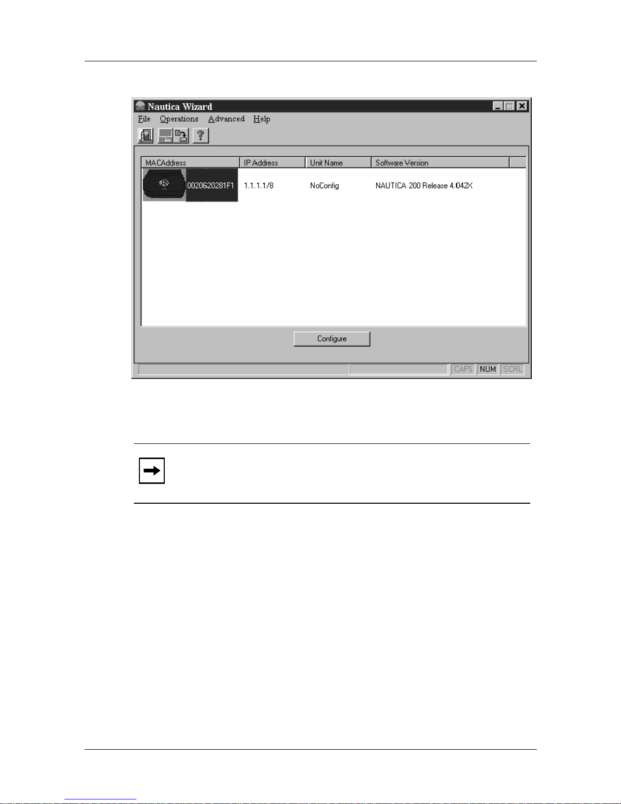
Once Nautica Wizard has found a device, the Nautica Wizard
Window, as shown in Figure 6-2
, will look as follows:
6-6 118814-A Rev. A
Page 69
Issue 1
Basic Procedures
Figure 6-2. Nautica Wizard Main Window
Note:
The Nautica Wizard window will display different icons
for the different Nautica products. The icon shown here
represents a Nautica 200 and a Nautica Clam.
All the connected devices will appear in the main window, one
below another. The icons for the devices will be displayed in
different colors depending on their status:
• Green The unit is connected and working properly.
• Blue The unit is connected and has no configuration.
• Grey The unit has no software loaded.
• Yellow The unit needs its configuration saved.
118814-A Rev. A 6-7
Page 70
Issue 1
Nautica Configuration Wizard Reference Guide
In order to change the settings for a device, you select it by
clicking on it once. The device will be highlighted and the menus
in the menu bar of the Nautica Wizard window will become
available.
The Nautica Wizard Menus
The menus can be found at the top of the Nautica Wizard
window; they are as follows:
• The File menu
• The Operations menu
• The Advanced menu
• The Help menu
The File Menu
Use this menu to exit Nautica Wizard.
There are several ways to exit Nautica Wizard:
• In the Nautica Wizard window, click on
• With the Nautica Wizard windo w acti ve, ho ld do wn [
the keyboard and press the [
F4
] key.
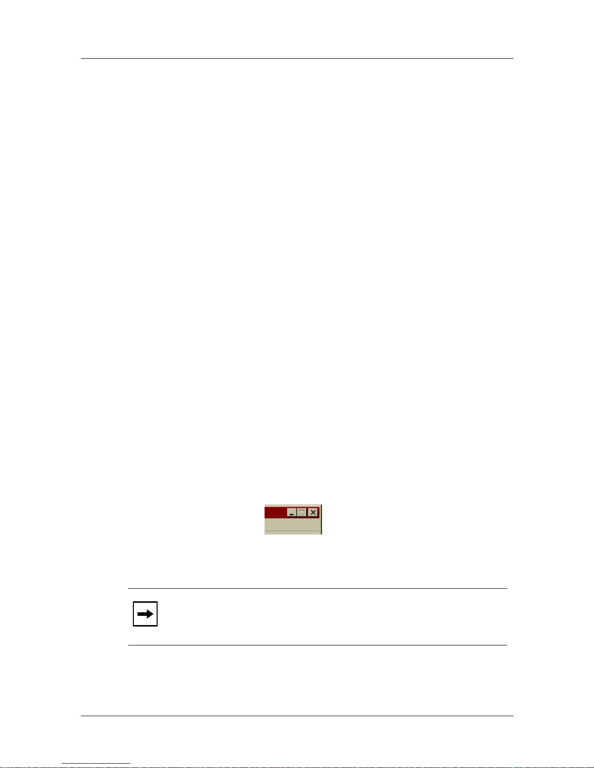
• Click once on the Exit button at the top right corner of the
Nautica Wizard screen.
Figure 6-3. Exit Button
Note:
Closing Nautica Wizard does not turn the Nautica router
off; it just exits Nautica Wizard.
File > Exit
ALT
] on
6-8 118814-A Rev. A
Page 71

Issue 1
Basic Procedures
The Operations Menu
The Operations menu contains four commands. These are used to
perform basic functions in Nautica Wizard and to launch Nautica
Watch. Nautica Watch is a virtual LED system that allows you to
monitor the status of your Nautica router in more detail.
For more information on Nautica W atch, refer to Chapter 15. The
other commands in the Operations menu are outlined in the
“Basic Nautica Wizard Operations
” section on page 6-11.
The Advanced Menu
The Advanced Nautica Wizard menu contains all the commands
and sub-commands you need to manually confi g ure y our Nautica
product, and to also set more advanced functions within the
router.
The commands in the Advanced menu are explained in more
detail in the following chapters.
The Help Menu
If at any time you require help on any field, press the [F1] key
while your cursor is in the relevant field. Help will launch
automatically and take you to the relevant section.
Calling Help from the Help menu allows you to search for less
specific options.
The Help menu also contains an About command. Clicking this
screen will display programming information for Nautica W izard,
including the version of the software you are using.
118814-A Rev. A 6-9
Page 72
Issue 1
Nautica Configuration Wizard Reference Guide
The Nautica Wizard Toolbar
Below the menu bar is the toolbar. The toolbar is a row of icons
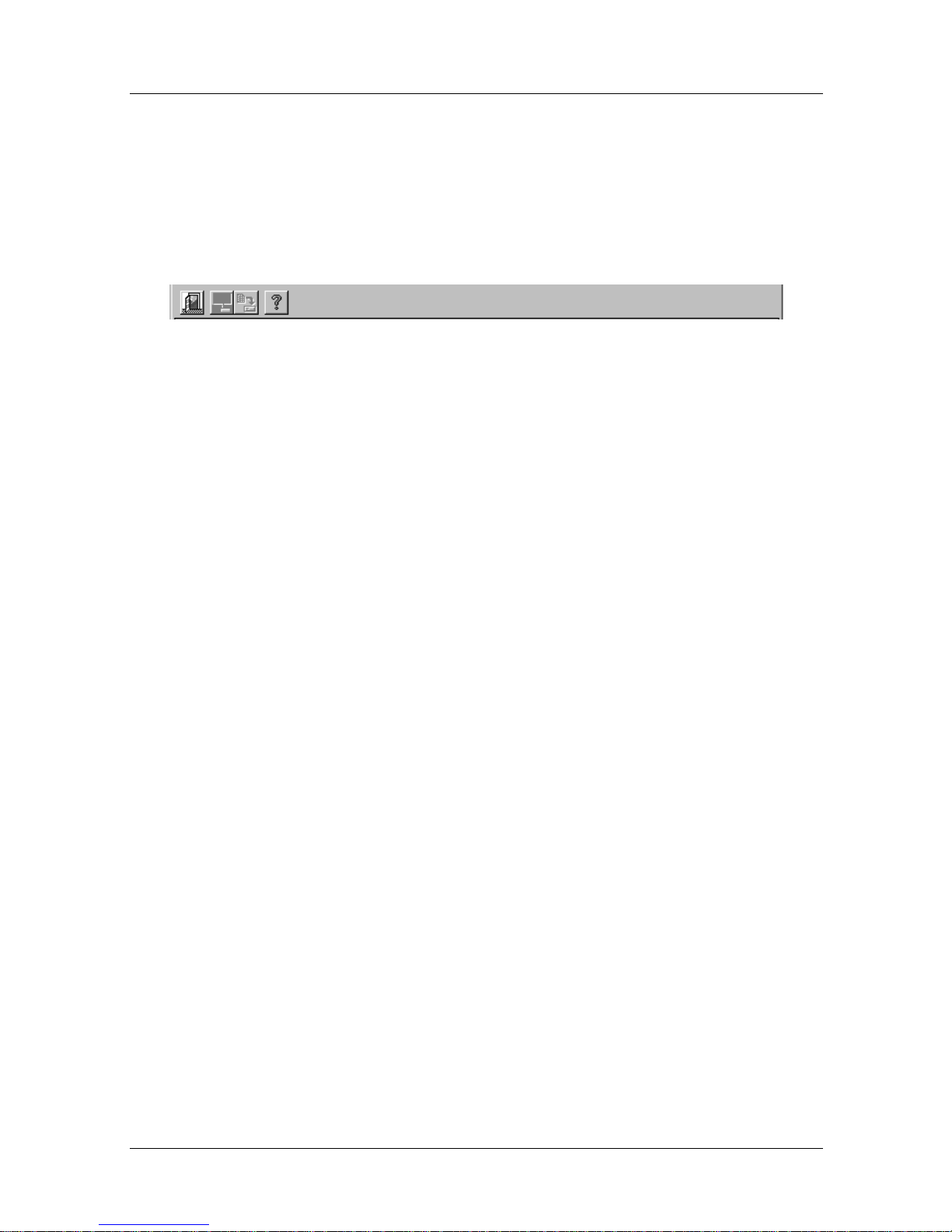
that allows you to perform some menu commands rather than
choosing the command itself from the relevant menu.
Figure 6-4. The Nautica Wizard Toolbar
The buttons are as follows:
• Exit Naut ica Wizard
• Launch NauticaWatch
• Configure selected unit using the Installation Assistant
•Launch Help
There is a larger Confi gure button at the bottom of the Nautica
Wizard window. Selecting a unit and clicking on this button
launches the Installation Assistant.
6-10 118814-A Rev. A
Page 73
Basic Nautica Wizard Operations
This section of the chapter deals with common tasks that you
need to perform on the Nautica 200.
Configuration Using Nautica Wizard
The Configure command will launch the Installation Assistant,
allowing you to re-enter basic configuration information. The
Assistant, as explained in Chapter 1, allows you to specify basic
configuration for a unit.
Issue 1
Basic Procedures
Note:
the settings have been returned to the defaults (page 6-11
1. Select the unit to configure in the Nautica Wizard main
2. Click on
3. The Installation Assistant (Ch ap ter 1) will launch.
Alternatively:
1. Select the unit to configure in the main Nautica Wizard
2. Click on the Configure button at the bottom of the
3. The Installation Assistant (Ch ap ter 1) will launch.
Once a unit is configured, it cannot be re-configured until
).
window (page 6-7
Operations > Configure
window (page 6-7
Nautica Wizard window.
).
.
).
Returning to the Default Configuration
The Default Configuration command deletes all the current
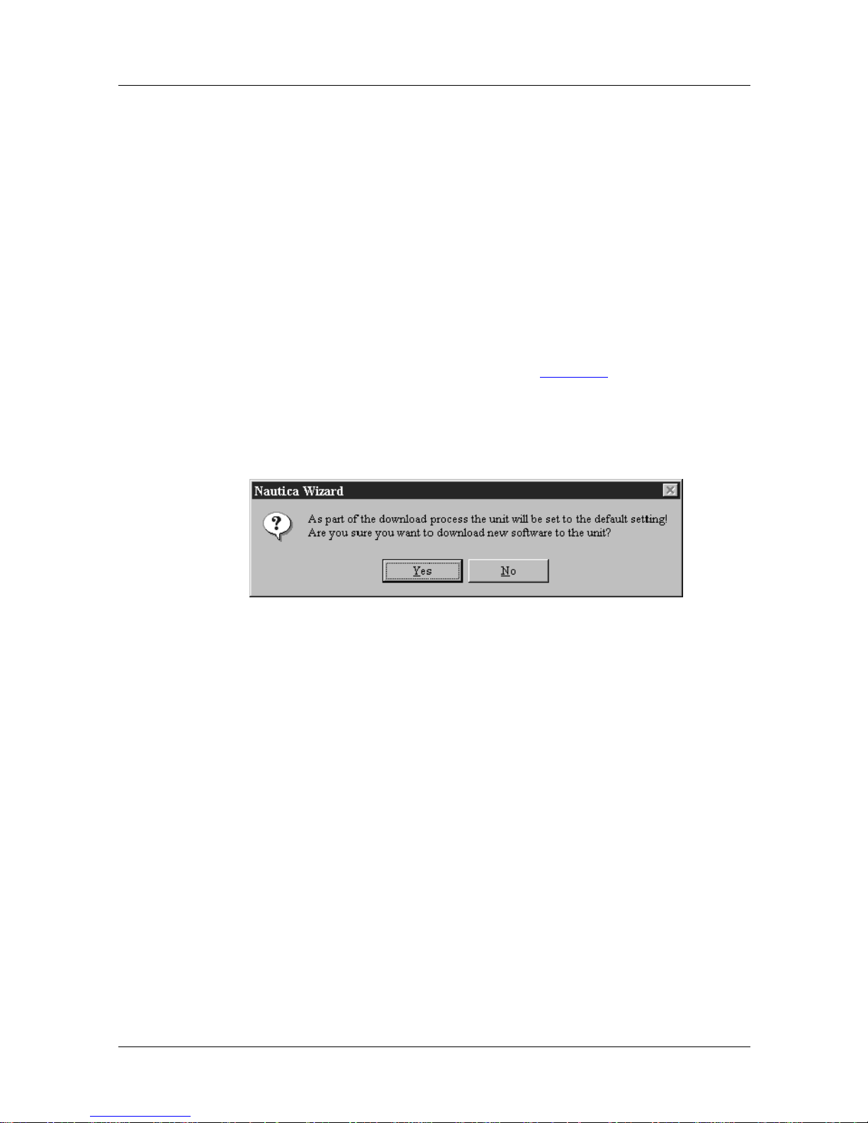
settings in your Nautica router and retu rns th em to the
manuafacturer’s default settings. At present there is no way to
recall these settings. If you do intend to delete your configuration,
it is best to take a note of the existing settings in case you need to
re-enter them in future.
118814-A Rev. A 6-11
Page 74
Issue 1
Nautica Configuration Wizard Reference Guide
1. Select the unit in the Nautica Wizard window (page 6-7).
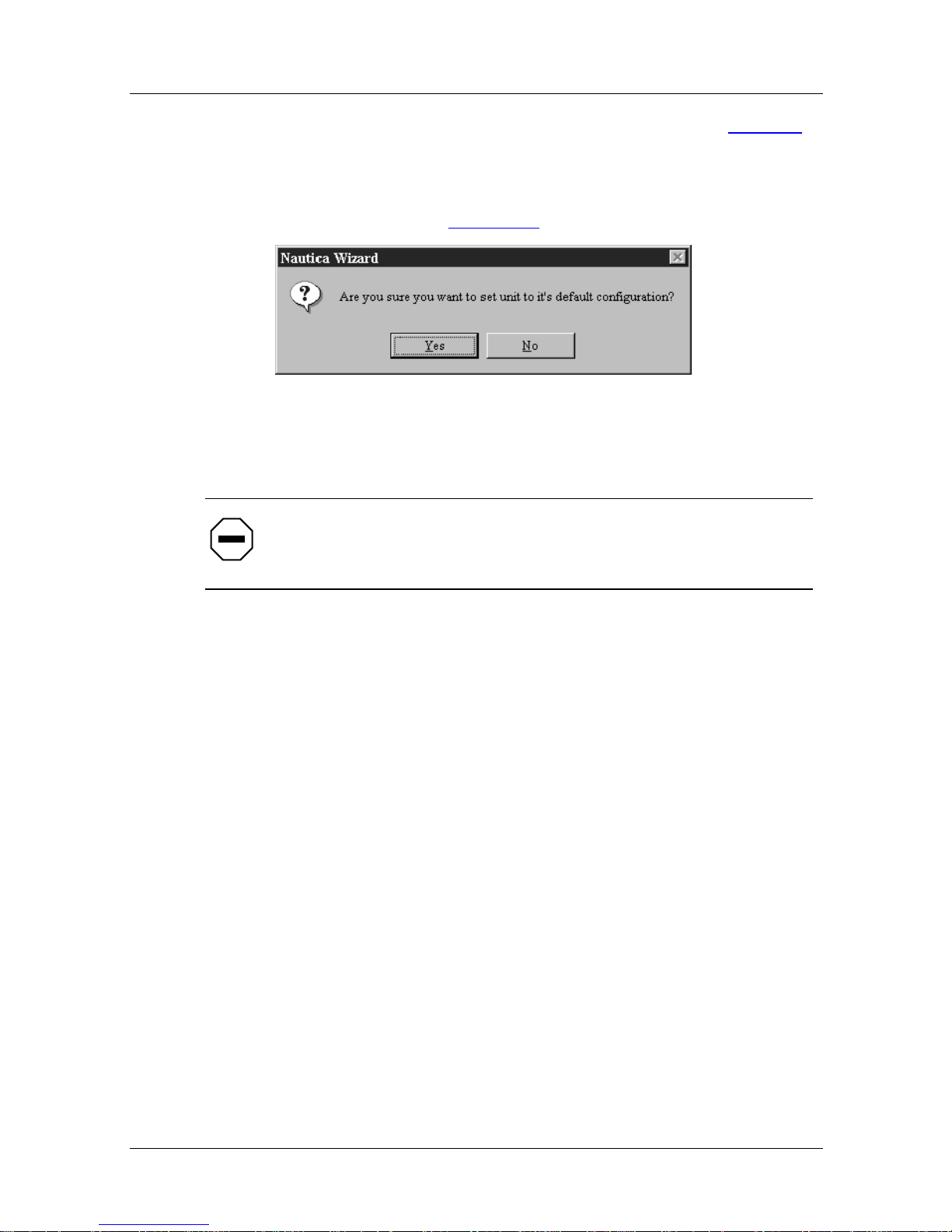
2. Click on
3. Click
the command (Figure 6-5
Operations > Set Unit to Default Configuration.
YES
to accept the default settings or NO to cancel
).
Figure 6-5. Accept/Reject Nautica Wizard Default
Settings
Caution:
You must reset the unit configuration in order to
download a new software version.
Downloading New Software
You only need to use this command if you receive an upgrade to
the router code. Make sure you have reset your configuration
before you download any new software.
Accessing the Bay Networks W eb Site
You will be notified of new Nautica Wizard releases as they are
made available. These files will be stored on the Bay Networks
website at http//www.b ay network s.com. You will need to copy
these files from the web site onto your PC before you can install
them.
To download these files, do the following:
1. Using your Internet browser, access the Bay Networks
web page at the above address.
2. There will be two files to choose from:
6-12 118814-A Rev. A
Page 75
Issue 1
Basic Procedures
• N200eu0.BAY (European Nautica routers)
• N200us0.BAY (North American Nautica routers)
3. Select the relevant file and download it to your PC.
Loading the New software into the Nautica 200
Once the relevant file has been downloaded from the Bay
Networks web site, do the following to load it into your Nautica
router:
1. Select the unit that is to receive the new software in the
Nautica Wizard main window (page 6-7
).
2. Click on
Software
Operations > Download New Nautica 200
.
3. The Download Confirmation window appears:
Figure 6-6. Download Confirmation Window
118814-A Rev. A 6-13
Page 76
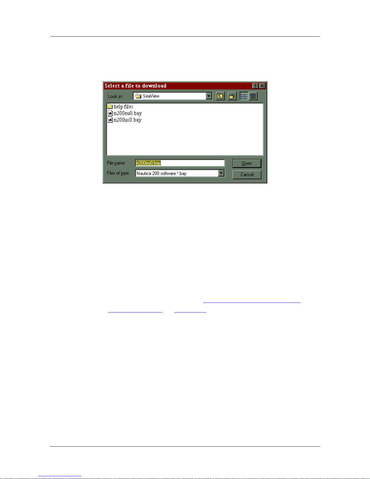
Issue 1
Nautica Configuration Wizard Reference Guide
4. Click on NO in the Download Confirmation window and
the download will be cancelled. Click on
Select a File to Download window will appear:
YES
and the
Figure 6-7. Select a File to Download Window
5. Change into the folder into which you copied the file fr om
the Bay Networks web site.
6. Select the new software file and click on the Open button.
7. The new software will be loaded into the Nautica 200.
Once downloaded, you will need to conf igure the un it with all the
relevant parameters. To automatically configure the unit, launch
the Installation Assistan t and refer to “Configuration Using
Nautica Wizard” on page 6-11. To manually configure the unit,
read the rest of this chapter.
Saving Configuration Changes
Changes you make to a Nautica router using Nautica Wizard are
implemented immediately by the unit. They are not, however,
saved . If you lea ve chan ges unsa v ed, you run the risk of losing the
changes you have made if the power is disconnected from the
Nautica unit, or the unit crashes.
To save the changes you have made, do the following:
6-14 118814-A Rev. A
Page 77
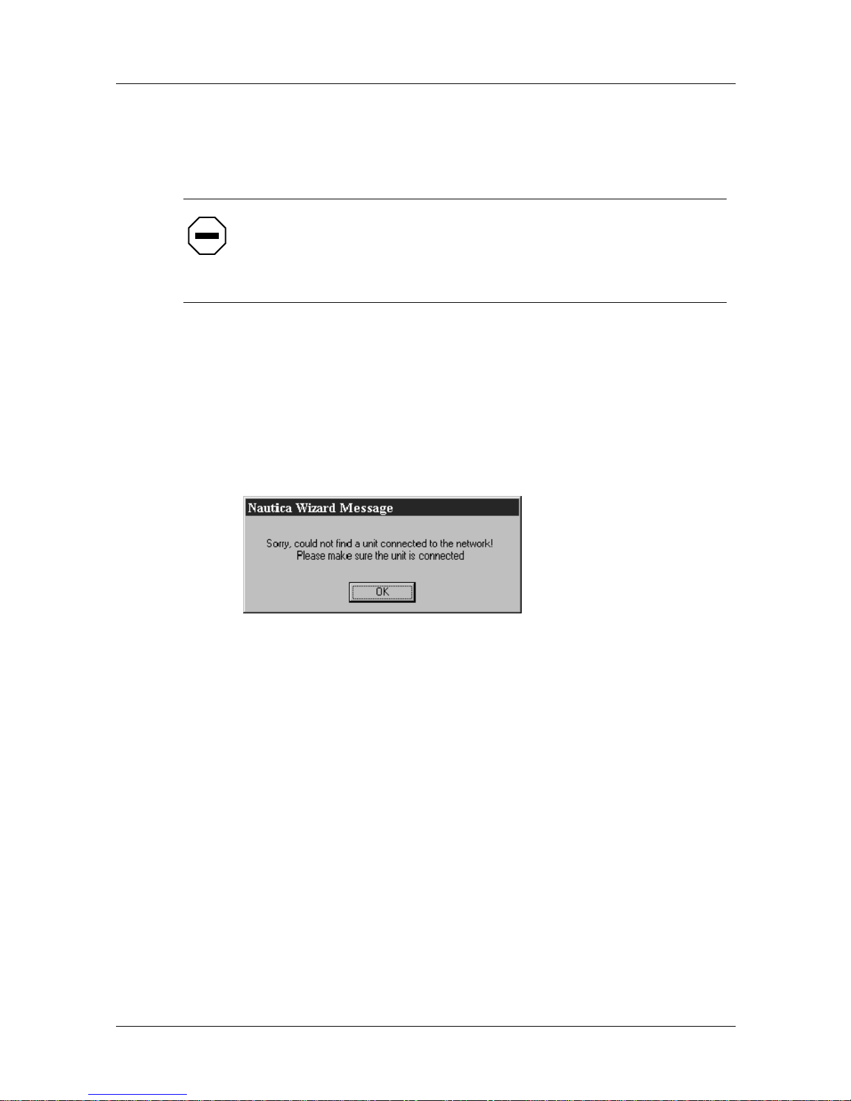
Issue 1
Basic Procedures
1. Select the unit which needs to be saved (it will be flashing
yellow in the Nautica Wizard window).
2. Click on
Caution:
the unit from the power supply, all changes you have made will
be lost. Changes will also be lost if the un it is rebooted without
first saving the new configuration.
Connection Failure
If no devices are attached to the network, or the devices are not
connected properly, Nautica Wizard will display the following
message:
Advanced > Save Configuration
.
If you do not Save the changes, and then disconnect
Figure 6-8. Connection Failure
Make sure the devices are connected properly to the LAN, or
check the settings for your PC to make sure it can communicate
with the LAN correctly. If Nautica Wizard continues not to find
the devices, consult the supplier of your equipment.
The following chapters deal with the v arious elements that can be
configured in more detail using Nautica W iza rd commands.
118814-A Rev. A 6-15
Page 78

Page 79

Chapter 7
Modifying System Settings
System settings are commands and settings that affect the whole
of the Nautica router rather than an in dividual element like a path
or route.
This chapter contains the following sections:
Amending System Settings
page 7-2
118814-A Rev. A 7-1
Page 80
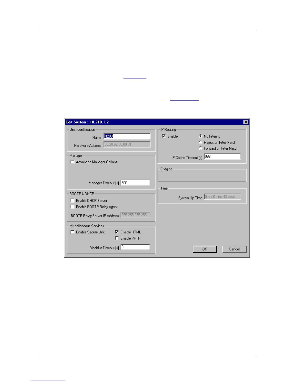
Issue 1
Nautica Configuration Wizard Reference Guide
Amending System Settings
To amend or view system settings, do the following:
1. Select the unit to be configured in the Nautica Wizard
window (page 6-6
).
2. Click on
Advanced > System.
3. The Edit System window (Figure 7-1) will appear:
Figure 7-1. Edit System Window
The various parameters in the Edit System window are contained
under separate headings. These are as follows:
7-2 118814-A Rev. A
Page 81

Unit Identification
The parameters set in the unit identification section of the Edit
System window name and locate the Nautica unit. These options
are also set in the Installation Assistant (See Chapters 1 to 4).
Parameter: Name
Default: A name entered using the Installation Assistant
Options: The Name you wish to associate with this Nautica router
Instructions: The name parameter is entered using the Installation
Issue 1
Modifying System Settings
(Chapters 2, 3 and 4)
(up to 32 characters long, no spaces)
Assistant. It is possible to enter a name manually into
this field. Type in the name you wish to call the unit.
Parameter: Hardware Addres s
Instructions: This is the unit’s MAC address. It is not possible to
Manager
Default: A twelve digit hexadecimal number
Options: This parameter cannot be changed by the user.
change this number.
The Manager options do not affect the way Nautica Wizard
operates. These parameters are designed to control the length of
time a manager session can be open using Nautica Router
Software Release 4 (BCC) and Advanced options concerning
OSPF opera tions on paths.
OSPF is not supported on the Nautica 200.
118814-A Rev. A 7-3
Page 82

Issue 1
Nautica Configuration Wizard Reference Guide
Parameter: Advanced Manager Options
Default: Disabled
Options: Dis abled, Enabled
Function: To allow more advanced path configuration
Instructions: Not necessary for the Nautica 200. Enabling this option
will allow extra OSPF features to be set for individual
paths.
Parameter: Manager Timeout (s)
Default: 300 (seconds)
Options: A time in seconds
Function: Sets the time a manager session (Telnet or
Instructions: This option does not affect the working of Nautica
BOOTP & DHCP
BOOTP Relay and Dynamic Host Configuration Protocol
(DHCP) are more advanced parameters within Nautica Wizard.
BOOTP Relay allows non-IP packets to be routed across your
network. For more information on BOOTP Relay, refer to the
Concepts section of the Help file.
DHCP allows a router to allocate IP addresses to clients as they
need to use the network. These addresses can be allocated
temporarily or permanently. For more information on DHCP refer
to Chapter 13 and the Concepts section of the Help file.
HyperTerminal) can be open when using Nautica Ro uter
Software Release 4 (BCC).
Wizard. It is only valid if you plan to use the manager.
7-4 118814-A Rev. A
Page 83

Issue 1
Modifying System Settings
Parameter: Enable DHCP Server
Default: Disabled
Options: Dis abled, Enabled
Function: Turns the Nautica 200 into a DHCP server.
Instructions: This parameter works in conjunctio n with the DHCP
server commands (C hapter 13). F or more information on
DHCP, refer to the Concepts section of the Help file.
Parameter: Enable BOOTP Relay Agent
Default: Disabled
Options: Dis abled, Enabled
Function: En a bling this option will forward BOOTP Relay
requests to the server specified in the BOOT P Rel ay
server IP Address parameter.
Instructions: If you want the Nautica router to forward BOOTP Relay
requests, then this option mus t be en abled. The BOOTP
server address must also be specified. For more
information on BOOTP Relay, refer to the Concepts
section of the Help file.
Parameter: BOOTP Relay Server IP Address
Default: 255.255.255.255
Options: The IP address of th e BOOTP-Relay server to which
BOOTP requests are sent.
Function: Forwards BOOTP Relay requests to the specified
address
Instructions: Leaving the default address here will cau se the unit to
118814-A Rev. A 7-5
forward BOOTP Relay requests along those paths you
have set to accept BOOTP Relay (page 8-7
).
Page 84

Issue 1
Nautica Configuration Wizard Reference Guide
If an IP address is specified here, BOOTP Relay requests
will be forwarded to this address and not along a
pre-defined path.
For more information on BOOTP Relay, refer to the
Concepts section of the Help file.
Miscellaneous Services
The miscellaneous features allow you to add extra security to the
unit, and turn on options lik e Hyper Text Markup Language
(HTML) and Point to Point Tunneling Protocol (PPTP).
Parameter: Enable Secure Unit
Default: Disabled
Options: Dis abled, Enabled
Function: Enabling this option adds an extra dimension to the
security of the unit.
Instructions: Incoming calls will only be accepted into the unit if they
match a path that already exists in the unit. Calls that do
not match any paths will be dropped.
Parameter: Enable HTML
Default: Enabled
Options: Enabled, Disabled
Function: Allows the unit to be accessed (Read Only) by a web
browser
7-6 118814-A Rev. A
Page 85

Issue 1
Modifying System Settings
Parameter: Enable PPTP
Default: Disabled
Options: Dis abled, Enabled
Function: Enables the Nautica router to be the instigator or
terminator of a Point to Point Tunneling Protocol (PPTP)
tunnel.
Instructions: If this parameter is enab led, then PPTP can also be
enabled in a path. (ISDN Number 1 has to be set to the
IP address of the originator/terminat or of the PPTP
tunnel (page 8-11
) or as an ISDN Multi Subscriber
Number (MSN) to provide the telephone number of the
PPTP host and IP address of the PPTP Tunnel
terminator.
For more general information on PPTP, refer to the
Concepts section of the Help file as well as the MSN
section of the ISDN chapter on page 11-2
.
Parameter: Blacklist Timeouts
Default: 0
Options: A time in seconds
Function: Paths are blacklisted if attempts to reach them fail.
Setting a time here specifies how long a path remains
blacklisted.
Instructions: When a path is blacklisted, all associated routes are
marked as unreachable. These decay (become outdated
and eventually get deleted). This allows ISDN connected
networks to use alternate routes if they are setup. A path
cannot be used if it is on the blacklist.
118814-A Rev. A 7-7
Page 86
Issue 1
Nautica Configuration Wizard Reference Guide
Leaving this parameter at the default of 0 specifies
exponential blacklisting. Each time a path is re-tried and
fails, the blacklist time is doub led.
IP Routing
The IP Routing option must be enabled if you wish to use IP
across your Nautica router. The Nautica 200 and Nautica CLAM
IP will only use IP, so leave this parameter enabled.
If you do intend to use IP, you may want to filter information to
and from certain users. IP filtering is set in this part of the
Systems window.
Parameter: Enable
Default: Enabled
Options: Enabled, Disabled
Function: Enables IP routing
Instructions: If disa bled, the Telnet facility is not available and only
local management of the unit via a terminal connected to
the serial port is possible.
Note:
The Nautica 200 and Nautica CLAM IP can on ly route
using IP.
7-8 118814-A Rev. A
Page 87

Modifying System Settings
Parameter: IP Filtering parameters
Default: NoFiltering
Options: NoFilt ering , Reject o n Filter Match, Forward on Filter
Match
Issue 1
Function: Us e d in conjunction with the
Filters
command, this parameter allows you to specify
how the Nautica router will use any filter pairs you may
have created.
Instructions: This attribute has three values:
• No Filtering This is the default value and if selected
will turn filtering off. If you do need to filter routes,
then use one of the other two options.
• Reject on Filter Match will only allow frame types
that do not match a predefined filter into the Nautica
router. Any frames that match the filter will be
dropped (not received by the unit).
• Forward on Filter Match will only allow frame
types that match a predefined filter into the unit. All
other frames will be dropped.
For more information on creating filters, turn to page 12-9
Advanced > TCP/IP >
.
Parameter: IP Cache Timeouts
Default: 998 seconds
Options: Any valid time in seconds
Function: Sets the limit for routes to be stored in the IP cache (page
Instructions: If a route is stored in the IP cache, it will be removed if it
Note:
overheads for the unit. 0 is not a valid configuration for this
parameter.
118814-A Rev. A 7-9
12-14)
has not been used for longer than the time specified here.
Any value below 30 seconds may cause excessive
Page 88

Issue 1
Nautica Configuration Wizard Reference Guide
Bridging
Bridging options are not visible when connected to a Nautica 200.
Time
This is a read only parameter that tells you how long the Nautica
unit you are monitoring has been powered up.
Parameter: System Up Time
Default: A unit in time
Options: Cannot be amended by the user
Function: The length of time the Nautica router has been running
since it was last powered up.
7-10 118814-A Rev. A
Page 89

Chapter 8
Configuring Paths
Paths are important in a Nautica router. They tell the unit
information about how to reach a specific destination. When a
unit is configured, there are two paths shown automatically; the
LAN01 path and a path called RemotePPP.
LAN01 is the path to the local network and is learned by the unit
automatically. RemotePPP is the path to the ISDN number setu p
when using the Installation Ass istant (Chapters 1 to 4).
This chapter includes the following sections:
The Path Table
Deleting a Path page 8-3
Editing the LAN01 Path page 8-3
page 8-2
118814-A Rev. A 8-1
Page 90
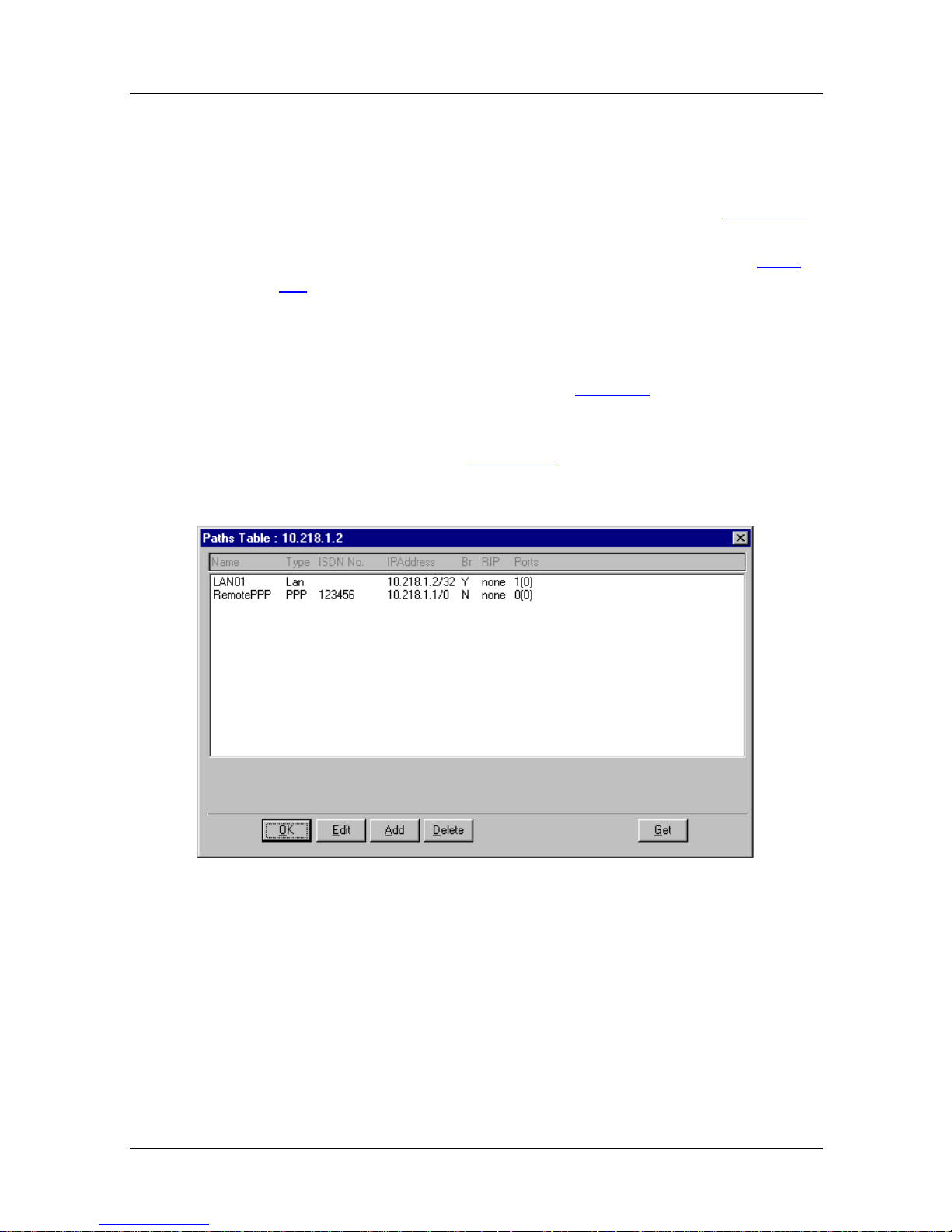
Issue 1
Nautica Configuration Wizard Reference Guide
The Path Table
As the unit makes and receive s calls it will learn new paths, and
these will be displayed in the Paths table as shown in Figure 8-1
The paths learned by the Nautica router will be deleted by the unit
automatically when they become blacklisted and unused (page
7-7).
To view the Paths table, do the following:
1. Select the unit that contains the paths yo u want to view in
the Nautica Wizard window (page 6-6
.
).
2. Click on
Advanced > Paths
3. The Paths table (Figure 8-1
.
) appears .
Figure 8-1. Paths Table
The path called RemotePPP was created by the Installation
Assistant. It is the path to the remote router you specified while
running the Installation Assistant. This path can be edited further.
The path called LAN01 can have some of its properties edited,
but ca nnot be deleted.
8-2 118814-A Rev. A
Page 91

Deleting a Path
To delete a path from the Paths table (Figure 8-1), do the
following:
1. In the Paths table select the path to delete.
2. Click on the Delete button.
Editing the LAN0 1 Path
The LAN01 path is a system generated path that po ints to the
local LAN. You cann ot edit all the properties for the path.
To display the LAN01 prop erties, do the following:
Issue 1
Configuring Paths
1. In the Nautica Wizard window (page 6-6
that contains the path to be edited.
2. Click on
3. In the Paths table ( Figure 8-1), click on the LAN01 path
and then click on the Edit button at the bottom of the
Paths t a ble.
4. The Edit Router LAN Path window (Figure 8-2
Advanced > Paths.
), select the unit
) appears.
118814-A Rev. A 8-3
Page 92
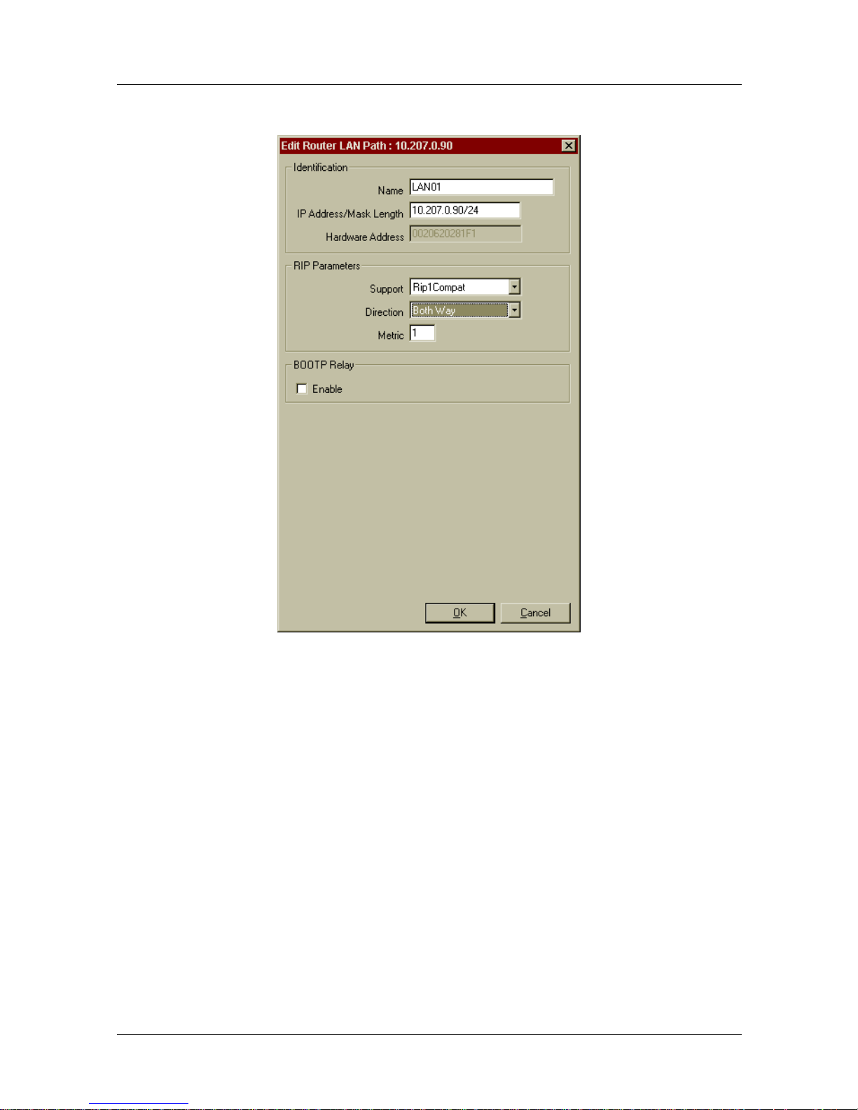
Issue 1
Nautica Configuration Wizard Reference Guide
Figure 8-2. Edit Router LAN Path
This screen contains various parameters grouped under three
headings. These parameters are described in the following pages.
Identification
Identification options are used to name the router and also to
assign an IP address to it. These parameters cannot be amended
for the LAN01 path.
8-4 118814-A Rev. A
Page 93
Parameter: Name
Default: LAN01
Options: This option cannot be changed by the user.
Issue 1
Configuring Paths
Note:
path that you have created yourself (page 8-8
You can only change the name of a path if it is a static
).
Parameter: IP Address/Mask Length
Default: A valid IP address
Options: The IP address of the local network (LAN)
Parameter: Hardware Addres s
Default: A twelve digit hexadecimal number
Options: Cannot be amended by the user
Function: This is the MAC address of the unit. It is system
generated and cannot be amended by the user.
RIP Parameters
Routing Information Protocol (RIP) specifies how information is
to be routed across your Nautica unit. Specify here the type of
RIP support you require and the direction in which that support
will operate.
118814-A Rev. A 8-5
Page 94

Issue 1
Nautica Configuration Wizard Reference Guide
Parameter: Support
Default: Rip1 Compat (Single Host addressing and Standard
Routing), None (Cul-d e-sac Routing)
Options: Rip1 Compat, Rip1, Rip2, Rip1 Subnet, None
Function: This is the type of IP support used on this path
Instructions: The optio ns for this parameter are as follows:
• Rip1 Compat: RIP2 packets are broadcast. This
option is the RIP1 Compatibility option as specified
in RFC 1723 and is most likely to work with older
RIP1 implementations where the new RIP2 features,
like subnet masking, may be useful.
• Rip1: RIP Version 1 packets are broadcast as per
RFC 1508.
• Rip2: RIP Version 2 packets are multicast to
224.0.0.9 as per RFC 1723.
• Rip1 Subnet: This is a modified version of RIP1
mode which allows Nautica routers to work in
networks where RIP1 must be used due to an
installed base of older routers. RIP1 packets are
broadcast, but when network routes are learnt via
RIP, the Nautica router applies a subnet mask as
follows:
If the route is within the same “natural” network as
the current router, the subnet mask of the LAN01
interface is used; otherwise the “natural” subnet
mask is applied to the route. This allows correct
operation of a router in a subnetted environment
where RIP1 is used.
• None: Selecting this value will turn RIP support off.
The unit will not send or receive RIP.
8-6 118814-A Rev. A
Page 95

Configuring Paths
Parameter: Direction
Default: Both Way
Options: Both Way, Block All, Send Only, Listen Only
Function: This parameter specifies the way IP will mov e along this
path.
Instructions: The optio ns for this parameter are as follows:
• Both Way: Calls will be sent and received along
this path.
• Block All: Calls will not be sent or received along
this path.
• Send Only: The unit will only sen d calls along this
path.
Issue 1
Parameter: Metric
Default: 1
Options: System generated
Function: The Metric is a system generated cost for this path and
BOOTP Relay
If this option is enabled, the BOOTP Relay requests can be passed
along this path. BOOTP Relay will route non-IP information
across the router.
• Listen Only: Calls will only be received along this
path.
should not be amended by the user.
118814-A Rev. A 8-7
Page 96

Issue 1
Nautica Configuration Wizard Reference Guide
Parameter: Enable
Default: Disabled
Options: Dis able, Enable
Function: Enables or disables BOOTP Relay
Instructions: Allows BOOTP Relay requests to be sent along this path
if the BOOTP Relay Agent parameter in the System
settings (page 7-5
) is left at the default 255.255.255.255
For more information on BOOTP Relay, refer to the
Concepts section of the Help file.
Adding and Editing Paths
Although the Nautica router you have purchased will learn paths
as it receives information from other routers and networks, you
will also need to create and edit some of your own paths in order
to reach other destinations.
To edit an existing path (not LAN01; see page 8-3
):
1. In the Nautica Wizard window, select the unit that
contains the path you want to edit.
2. Click on
Advanced > Paths.
3. In the Paths table ( Figure 8-1) select the path to modify.
4. Click on the Edit button.
5. The PPP Path ‘Main’ Parameters window will open
(Figure 8-3
Turn to page 8-9
To add a path, you need to display the Paths table (Figure 8-1
).
for information on this window.
):
1. In the Nautica Wizard window, select the unit to which
you want to add the path.
2. Click on
3. The Paths table appears. (Figure 8-1)
4. Click on the Add button to add a path.
8-8 118814-A Rev. A
Advanced > Paths.
Page 97
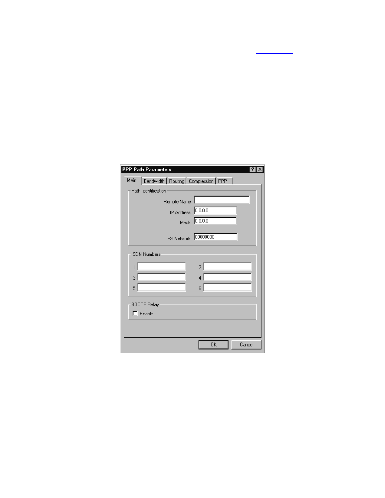
5. The PPP Path Parameters window (Figure 8-3) will
appear. This window is tabbed, and the first tab is the
Main tab.
Path ‘Main’ Parameters
The Main parameters are concerned with naming the path for
easy identification and also assigning the ISDN numbers that this
path will call when activated.
Issue 1
Configuring Paths
Figure 8-3. PPP Path ‘Main’ Parameters
This tab contains the main PPP parameters for the path. The
parameters on this tab are grouped and described in the next few
paragraphs.
118814-A Rev. A 8-9
Page 98

Issue 1
Nautica Configuration Wizard Reference Guide
Path Identification
Path Identification allows you to mark this path as unique by
giving it a name and IP address. The name and IP address are
those of the remote router to which this path attaches.
Parameter: Remote Name
Default: (Blank)
Options: A valid router name
Function: The name of the router at the remote end of the path
Parameter: IP Address
Default: (Blank)
Options: A valid IP address
Function: The IP address of the remote router
Instructions: The IP address of the remote unit to be reached along
this path. This parameter is only used in a numbered link
or if you are working with single host addressing
(Chapter 2).
Parameter: Mask
Default: (Blank)
Options: A valid subnet mask
Function: A subnet ma sk for the IP address entered into the
previou s parame ter.
8-10 118814-A Rev. A
Page 99

Configuring Paths
Parameter: IPX Network
Default: 00000000
Options: The Nautica 200 does not support IPX; you cannot
change this parameter.
ISDN Numbers
ISDN numbers are the ISDN telephone numbers to be used when
this path is activated.
Parameter: ISDN Numbers (1 to 6)
Default: (Blank)
Issue 1
Options: A maximum of six valid ISDN numbers or a PPTP
originator IP address
Function: Th e ISD N numbers to be called when this path is used,
or the IP Address of the originator of a PPTP tunnel
Instructions: The first number is called three times; if that is
unavailable the second number is dialled, and so on.
If a call fails on all six numbers, the path will be
blacklisted for the amount of time set in the Blacklist
Timeouts parameter in the System window (page 7-7
If this path is to run data over voice, to take advantage of
cheaper voice tariffs, perhaps, then precede the
telephone number entered as ISDN Number 1 with a
‘V’:
V01234567890
Note:
The ‘V’ entered to specify data over voice must be
entered in upper case.
).
118814-A Rev. A 8-11
Page 100

Issue 1
Nautica Configuration Wizard Reference Guide
Other modifiers that can be entered before telephone
numbers are shown in Table 8-1
Table 8-1. ISDN Telephone Number Modifiers
Modifier Description
! V120 Calls
#56k Calls
$ Modem Calls
FFax Calls
If PPTP has been enabled in the System settings (page
7-7), then the first number here needs to be set up as the
IP address of the originator of the PPTP tunnel, or the
Terminator of the tunnel. The following syntax must be
used:
.
u192.1.1.25
BOOTP Relay
BOOTP Relay allows non-IP information to be routed across your
Nautica unit. If BOOTP Relay information is to be passed along
this path, then you must enable this parameter.
Parameter: Enable
Default: Disabled
Options: Dis abled, Enabled
Function: If this path is u sed to pass BOOTP Relay information
then you must select the Enable option. BOOTP Relay
must also be turned on in the System window (page 7-5
).
8-12 118814-A Rev. A
 Loading...