

Bay Networks Baystream 7, Remote Annex, BayDVS, Bay Dial VPN Configuration And Troubleshooting Manual

Configuring and
Troubleshooting
Bay Dial VPN Services
(DVS)
Remote Annex Software Version 14.1
BayStream Multiservice Software Version 7.2
BayStream Site Manager Software Version 7.2
February 1998

4401 Great America Parkway 8 Federal Street
Santa Clara, CA 95054 Billerica, MA 01821
Copyright © 1998 Bay Networks, Inc.
All rights reserved. Printed in the USA. February 1998.
The information in this document is subject to change without notice. The statements, configurations, technical data,
and recommendations in this document are believed to be accurate and reliable, but are presented without express or
implied warranty . Users must tak e full responsibility for their applications of an y products specified in this document.
The information in this document is proprietary to Bay Networks, Inc.
The software described in this document is furnished under a license agreement and may only be used in accordance
with the terms of that license. A summary of the Software License is included in this document.
Restricted Rights Legend
Use, duplication, or disclosure by the United States Government is subject to restrictions as set forth in subparagraph
(c)(1)(ii) of the Rights in Technical Data and Computer Software clause at DFARS 252.227-7013.
Notice for All Other Executive Agencies
Notwithstanding any other license agreement that may pertain to, or accompany the delivery of, this computer
software, the rights of the United States Government regarding its use, reproduction, and disclosure are as set forth in
the Commercial Computer Software-Restricted Rights clause at FAR 52.227-19.
Trademarks
BCN, BLN, and Bay Networks are registered trademarks and Annex Manager, ASN, BaySecure Access Control,
BayStream, MSX, Quick2Config, RAC, Remote Annex, System 5000, and the Bay Networks logo are trademarks of
Bay Networks, Inc.
Microsoft, MS, MS-DOS, Win32, Windows, and Windows NT are registered trademarks of Microsoft Corporation.
All other trademarks and registered trademarks are the property of their respective owners.
Statement of Conditions
In the interest of improving internal design, operational function, and/or reliability, Bay Networks, Inc. reserves the
right to make changes to the products described in this document without notice.
Bay Networks, Inc. does not assume any liability that may occur due to the use or application of the product(s) or
circuit layout(s) described herein.
Portions of the code in this software product may beCopyright © 1988, Regents of the University of California. All
rights reserved. Redistribution and use in source and binary forms of such portions are permitted, provided that the
above copyright notice and this paragraph are duplicated in all such forms and that any documentation, advertising
materials, and other materials related to such distribution and use acknowledge that such portions of the software were
developed by the University of California, Berkeley. The name of the University may not be used to endorse or
promote products derived from such portions of the software without specific prior written permission.
SUCH PORTIONS OF THE SOFTWARE ARE PROVIDED “AS IS” AND WITHOUT ANY EXPRESS OR
IMPLIED WARRANTIES, INCLUDING, WITHOUT LIMITATION, THE IMPLIED WARRANTIES OF
MERCHANTABILITY AND FITNESS FOR A PARTICULAR PURPOSE.
In addition, the program and information contained herein are licensed only pursuant to a license agreement that
contains restrictions on use and disclosure (that may incorporate by reference certain limitations and notices imposed
by third parties).
ii BayStream Multiservice Software Version 7.2 115623B Rev. 00

Bay Networks, Inc. Software License Agreement
NOTICE:
installing the hardware unit with pre-enabled software (each of which is referred to as “Software” in this Agreement).
BY COPYING OR USING THE SOFTWARE, Y OU A CCEPT ALL OF THE TERMS AND CONDITIONS OF THIS
LICENSE A GREEMENT. THE TERMS EXPRESSED IN THIS A GREEMENT ARE THE ONLY TERMS UNDER
WHICH BAY NETWORKS WILL PERMIT YOU TO USE THE SOFTWARE. If you do not accept these terms and
conditions, return the product, unused and in the original shipping container, within 30 days of purchase to obtain a
credit for the full purchase price.
1. License Grant.
nonexclusive, nontransferable license: a) to use the Software either on a single computer or, if applicable, on a single
authorized device identified by host ID, for which it was originally acquired; b) to copy the Software solely for backup
purposes in support of authorized use of the Software; and c) to use and copy the associated user manual solely in
support of authorized use of the Software by Licensee. This license applies to the Software only and does not extend
to Bay Networks Agent software or other Bay Networks software products. Bay Networks Agent software or other
Bay Networks software products are licensed for use under the terms of the applicable Bay Networks, Inc. Software
License Agreement that accompanies such software and upon payment by the end user of the applicable license fees
for such software.
2. Restrictions on use; reservation of rights.
Bay Networks and/or its licensors retain all title and ownership in both the Software and user manuals, including any
revisions made by Bay Networks or its licensors. The copyright notice must be reproduced and included with any
copy of any portion of the Software or user manuals. Licensee may not modify, translate, decompile, disassemble, use
for any competitive analysis, reverse engineer, distribute, or create derivative works from the Software or user
manuals or any copy, in whole or in part. Except as expressly provided in this Agreement, Licensee may not copy or
transfer the Software or user manuals, in whole or in part. The Software and user manuals embody Bay Networks’ and
its licensors’ confidential and proprietary intellectual property. Licensee shall not sublicense, assign, or otherwise
disclose to any third party the Software, or any information about the operation, design, performance, or
implementation of the Software and user manuals that is confidential to Bay Networks and its licensors; however,
Licensee may grant permission to its consultants, subcontractors, and agents to use the Software at Licensee’s f acility,
provided they have agreed to use the Software only in accordance with the terms of this license.
3. Limited warranty.
installed and operated on Bay Networks hardware or other equipment it is originally licensed for, to function
substantially as described in its accompanying user manual during its warranty period, which begins on the date
Software is first shipped to Licensee. If any item of Software fails to so function during its warranty period, as the sole
remedy Bay Networks will at its discretion provide a suitable fix, patch, or workaround for the problem that may be
included in a future Software release. Bay Networks further warrants to Licensee that the media on which the
Software is provided will be free from defects in materials and workmanship under normal use for a period of 90 days
from the date Software is first shipped to Licensee. Bay Networks will replace defective media at no charge if it is
returned to Bay Networks during the warranty period along with proof of the date of shipment. This warranty does not
apply if the media has been damaged as a result of accident, misuse, or abuse. The Licensee assumes all responsibility
for selection of the Software to achieve Licensee’s intended results and for the installation, use, and results obtained
from the Software. Bay Networks does not warrant a) that the functions contained in the software will meet the
Licensee’s requirements, b) that the Software will operate in the hardw are or softw are combinations that the Licensee
may select, c) that the operation of the Software will be uninterrupted or error free, or d) that all defects in the
operation of the Software will be corrected. Bay Networks is not obligated to remedy any Software defect that cannot
be reproduced with the latest Software release. These warranties do not apply to the Software if it has been (i) altered,
except by Bay Networks or in accordance with its instructions; (ii) used in conjunction with another vendor’s product,
resulting in the defect; or (iii) damaged by improper environment, abuse, misuse, accident, or negligence. THE
FOREGOING WARRANTIES AND LIMITATIONS ARE EXCLUSIVE REMEDIES AND ARE IN LIEU OF ALL
OTHER WARRANTIES EXPRESS OR IMPLIED, INCLUDING WITHOUT LIMITA TION ANY W ARRANTY OF
MERCHANTABILITY OR FITNESS FOR A PARTICULAR PURPOSE. Licensee is responsible for the security of
Please carefully read this license agreement before copying or using the accompanying software or
Bay Networks, Inc. (“Bay Networks”) grants the end user of the Software (“Licensee”) a personal,
The Software and user manuals are protected under copyright laws.
Bay Networks warrants each item of Software, as delivered by Bay Networks and properly
115623B Rev. 00 BayStream Multiservice Software Version 7.2 iii

Configuring and Troubleshooting Bay Dial VPN Services
its own data and information and for maintaining adequate procedures apart from the Software to reconstruct lost or
altered files, data, or programs.
4. Limitation of liability.
COST OF SUBSTITUTE PROCUREMENT; SPECIAL, INDIRECT, INCIDENTAL, OR CONSEQUENTIAL
DAMAGES; OR ANY DAMAGES RESULTING FROM INACCURATE OR LOST DATA OR LOSS OF USE OR
PROFITS ARISING OUT OF OR IN CONNECTION WITH THE PERFORMANCE OF THE SOFTWARE, EVEN
IF BAY NETWORKS HAS BEEN ADVISED OF THE POSSIBILITY OF SUCH DAMAGES. IN NO EVENT
SHALL THE LIABILITY OF BAY NETWORKS RELATING TO THE SOFTWARE OR THIS AGREEMENT
EXCEED THE PRICE PAID TO BAY NETWORKS FOR THE SOFTWARE LICENSE.
5. Government Licensees.
by or on behalf of the United States Government. The Software and documentation are commercial products, licensed
on the open market at market prices, and were developed entirely at private expense and without the use of any U.S.
Government funds. The license to the U.S. Government is granted only with restricted rights, and use, duplication, or
disclosure by the U.S. Government is subject to the restrictions set forth in subparagraph (c)(1) of the Commercial
Computer Software––Restricted Rights clause of FAR 52.227-19 and the limitations set out in this license for civilian
agencies, and subparagraph (c)(1)(ii) of the Rights in Technical Data and Computer Software clause of DFARS
252.227-7013, for agencies of the Department of Defense or their successors, whichever is applicable.
6. Use of Software in the European Community.
European Community. If Licensee uses the Software within a country in the European Community, the Software
Directive enacted by the Council of European Communities Directive dated 14 May, 1991, will apply to the
examination of the Software to facilitate interoperability. Licensee agrees to notify Bay Networks of any such
intended examination of the Software and may procure support and assistance from Bay Networks.
7. Term and termination.
Bay Networks’ copyright in the Software and user manuals will cease being effective at the date of expiration of the
Bay Networks copyright; those restrictions relating to use and disclosure of Bay Networks’ confidential information
shall continue in effect. Licensee may terminate this license at any time. The license will automatically terminate if
Licensee fails to comply with any of the terms and conditions of the license. Upon termination for any reason,
Licensee will immediately destroy or return to Bay Networks the Software, user manuals, and all copies. Bay
Networks is not liable to Licensee for damages in any form solely by reason of the termination of this license.
8. Export and Re-export.
or information without first obtaining any required export licenses or other governmental approvals. Without limiting
the foregoing, Licensee, on behalf of itself and its subsidiaries and affiliates, agrees that it will not, without first
obtaining all export licenses and approvals required by the U.S. Government: (i) export, re-export, transfer, or divert
any such Software or technical data, or any direct product thereof, to any country to which such exports or re-exports
are restricted or embargoed under United States export control laws and regulations, or to any national or resident of
such restricted or embargoed countries; or (ii) provide the Software or related technical data or information to any
military end user or for any military end use, including the design, development, or production of any chemical,
nuclear, or biological weapons.
9. General.
If any provision of this Agreement is held to be invalid or unenforceable by a court of competent
jurisdiction, the remainder of the provisions of this Agreement shall remain in full force and effect. This Agreement
will be governed by the laws of the state of California.
Should you have any questions concerning this Agreement, contact Bay Networks, Inc., 4401 Great America Parkway ,
P.O. Box 58185, Santa Clara, California 95054-8185.
LICENSEE ACKNOWLEDGES THAT LICENSEE HAS READ THIS AGREEMENT, UNDERSTANDS IT, AND
AGREES TO BE BOUND BY ITS TERMS AND CONDITIONS. LICENSEE FURTHER AGREES THAT THIS
AGREEMENT IS THE ENTIRE AND EXCLUSIVE AGREEMENT BETWEEN BAY NETWORKS AND
LICENSEE, WHICH SUPERSEDES ALL PRIOR ORAL AND WRITTEN AGREEMENTS AND
COMMUNICATIONS BETWEEN THE PARTIES PERTAINING TO THE SUBJECT MATTER OF THIS
AGREEMENT. NO DIFFERENT OR ADDITIONAL TERMS WILL BE ENFORCEABLE AGAINST BAY
NETWORKS UNLESS BAY NETWORKS GIVES ITS EXPRESS WRITTEN CONSENT, INCLUDING AN
EXPRESS WAIVER OF THE TERMS OF THIS AGREEMENT .
IN NO EVENT WILL BAY NETWORKS OR ITS LICENSORS BE LIABLE FOR ANY
This provision applies to all Software and documentation acquired directly or indirectly
This provision applies to all Software acquired for use within the
This license is effective until terminated; however, all of the restrictions with respect to
Licensee agrees not to export, directly or indirectly, the Software or related technical data
iv BayStream Multiservice Software Version 7.2 115623B Rev. 00

Contents
Chapter 1
Planning for Dial VPN
Dial VPN Overview .........................................................................................................1-1
How a Dial VPN Network Functions ...............................................................................1-2
Dial VPN Basic Configuration Components ....................................................................1-4
Remote/Dial-In Node(s) ...........................................................................................1-4
Service Provider Network ........................................................................................1-4
Network Access Server .....................................................................................1-4
Gateway ............................................................................................................. 1-5
Tunnel Management Server ..............................................................................1-6
Customer/Home/Internet Service Provider Network ................................................1-6
Customer Premise Equipment (CPE) ................................................................1-6
RADIUS Authentication Server ..........................................................................1-7
Dial VPN Network Planning Worksheet ..........................................................................1-7
At the Dial VPN Service Provider’s Site ...................................................................1-8
For Each Destination Site ........................................................................................1-9
For Each Remote Node .........................................................................................1-10
Additional Planning Information .............................................................................1-11
Where to Go Next .........................................................................................................1-11
Chapter 2
Dial VPN Network Concepts
What is Tunneling? .........................................................................................................2-1
Implementing Dial VPN at Your Site ................................................................................2-2
How Tunnel Management Works ....................................................................................2-5
Tunnel Management in an erpcd-based Network ....................................................2-5
Tunnel Management in a RADIUS-only Network .....................................................2-6
How the TMS Database Works ................................................................................2-6
Dynamically Allocating IP Addresses .............................................................................2-7
115623B Rev. 00 BayStream Multiservice Software Version 7.2 v

Using DHCP for Dynamic IP Address Allocation .....................................................2-7
How DHCP Works ....................................................................................................2-8
Using RADIUS for Dynamic IP Address Allocation ................................................2-10
Starting the Connection ................................................................................................2-10
A Day in the Life of a Packet .........................................................................................2-13
How a Packet Moves Through a Dial VPN Network ...............................................2-15
How a Packet Returns to the Remote Node ..........................................................2-16
When Does Dial VPN Tear Down the Tunnel? ........................................................2-18
Chapter 3
Setting Up a Dial VPN Network
Dial VPN Network Hardware Requirements ...................................................................3-1
Where to Find Hardware Installation Information .....................................................3-2
Additional Configuration Considerations ..................................................................3-3
Configuring the IP Interface .....................................................................................3-3
Configuring the Dial VPN Network Software ..................................................................3-4
Configuring Local Authentication Using the ACP ...........................................................3-5
Chapter 4
Configuring the Remote Annex
Installing and Configuring the Annex Software ...............................................................4-2
Loading Software and Booting the Annex ......................................................................4-7
Configuring Active RIP ...................................................................................................4-8
Defining Routes ........................................................................................................4-8
Configuring the Annex to Advertise RIP 1 and/or RIP 2 Updates ............................4-9
Chapter 5
Configuring TMS for an
erpcd
-based Network
Managing TMS Using the TMS Default Database ..........................................................5-2
Using Tunnel Management Commands ..........................................................................5-4
Tunnel Management Commands ....................................................................................5-4
Command Arguments .....................................................................................................5-5
Alternatives to the Default Database ............................................................................5-11
TMS System Log (Syslog) Messages ..........................................................................5-12
vi BayStream Multiservice Software Version 7.2 115623B Rev. 00

Chapter 6
Configuring TMS Using Local RADIUS
How It Works ..................................................................................................................6-1
Tunnel Negotiation Message Sequence .........................................................................6-3
Handling Access Messages .....................................................................................6-5
Using RADIUS Accounting .......................................................................................6-5
Service Provider Accounting Messages ..................................................................6-6
Gateway Accounting Messages ...............................................................................6-7
RADIUS Attributes That Support Tunneling ....................................................................6-8
Managing the TMS Default Database .............................................................................6-9
TMS Parameters for
erpcd
-based and RADIUS-only Tunnels .....................................6-10
TMS System Log (Syslog) Messages ..........................................................................6-11
Chapter 7
Configuring the Gateway
Using Site Manager to Configure the Gateway ..............................................................7-1
Chapter 8
Configuring IPX as the Routing Protocol
Setting Up Dial VPN to Use IPX .....................................................................................8-3
Configuring the Dial-In Node for IPX ........................................................................8-3
Configuring the Network Access Server for IPX ......................................................8-4
Configuring IPX on the CPE router with Site Manager ............................................8-5
Configuring the CPE Router Frame Relay Connection with IPX ..............................8-7
Configuring Standards-Based IPX (IPXCP) ...................................................................8-8
Configuring IPX on the Customer Network RADIUS Server ..........................................8-8
Chapter 9
Requirements Outside the Dial VPN Network
Configuring a Static Route and an Adjacent Host ..........................................................9-2
Configuring a Bay Networks CPE Router Using Site Manager ................................9-3
Configuring the Adjacent Host and Static Routes ....................................................9-4
Configuring an Adjacent Host Between the CPE and the Gateway .........................9-6
Configuring a Static Route Between the CPE and the Gateway ..............................9-6
Configuring the CPE Frame Relay Circuit with Site Manager ........................................9-7
Installing and Configuring BSAC on the Home Network ................................................9-8
115623B Rev. 00 BayStream Multiservice Software Version 7.2 vii

Chapter 10
Managing a Dial VPN Network
Enabling and Activating Dial VPN .................................................................................10-2
What Happens When a User Dials In to a Dial VPN Network ......................................10-2
How Dynamic IP Addressing Works .............................................................................10-3
Assigning Addresses ..............................................................................................10-3
Upgrading and Changing Your Dial VPN Network ........................................................10-6
Removing Dial VPN from Your Network ........................................................................10-6
Chapter 11
Troubleshooting
What’s in This Chapter ..................................................................................................11-1
Preventing Problems ....................................................................................................11-2
Preparing to Troubleshoot .............................................................................................11-4
Troubleshooting Worksheet ....................................................................................11-4
Using the System Logs (syslogs) to Diagnose Problems ......................................11-8
Getting a Snapshot of the Current Status ..............................................................11-9
Troubleshooting Specific Protocols .............................................................................11-15
Troubleshooting a Site Manager Problem ...................................................................11-15
Troubleshooting Remote Annex Problems .................................................................11-16
Tracing a Packet’s Path at the Remote Annex .....................................................11-22
Troubleshooting Tunnel Problems ...............................................................................11-24
Appendix A
Additional Planning Information
Appendix B
Syslog Messages
Remote Annex Syslog Messages .................................................................................. B-1
TMS Syslog Messages .................................................................................................. B-3
Appendix C
Using Quick2Config and Annex Manager
Configuring Using Quick2Config Annex and Annex Manager .................................C-1
Installing and Configuring the Remote Annex Software ..........................................C-1
Loading Software and Booting the Remote Annex .................................................C-6
Configuring the Annex to Accept RIP 1 and/or RIP 2 Packets ................................C-6
Authenticating Incoming RIP 2 Updates and Requests ..........................................C-7
viii BayStream Multiservice Software Version 7.2 115623B Rev. 00

Glossary
Index
Configuring Active RIP ............................................................................................ C-9
Defining Routes .......................................................................................................C-9
Configuring the Annex to Advertise RIP Updates ...................................................C-9
115623B Rev. 00 BayStream Multiservice Software Version 7.2 ix

x BayStream Multiservice Software Version 7.2 115623B Rev. 00

Figures
Figure 1-1. Dial VPN Network Providing Connections to Different Destination Types 1-3
Figure 2-1. The Path of a Packet ................................................................................2-2
Figure 2-2. Connecting the Dial VPN LAN and WAN .................................................2-3
Figure 2-3. DHCP Operational Timeline .....................................................................2-9
Figure 2-4. Packet Encapsulation and Decapsulation Process ................................2-14
Figure 2-5. Sending a Packet to a Remote Node .....................................................2-17
Figure 2-6. Static Routes from a CPE Router to a Dial VPN Gateway .....................2-18
Figure 6-1. Simplified Dial VPN Network ....................................................................6-2
Figure 6-2. Message Exchanges Supporting RADIUS TMS Operations ...................6-4
Figure 8-1. Dial VPN Network Using IPX ...................................................................8-2
Figure 9-1. Static Route Between the CPE Router and the Gateway ........................9-2
Figure 10-1. Dial VPN Dynamic IP Address Management Sequence ........................10-5
Figure 11-1. Network Topology for
ping -t
Examples ...............................................11-23
115623B Rev. 00 BayStream Multiservice Software Version 7.2 xi


Tables
Table 3-1. Where to Find Installation Information ....................................................3-2
Table 4-1. Where to Find Configuration Information .................................................4-1
Table 5-1. Tunnel Management Commands .............................................................5-4
Table 5-2. tms_dbm Command Arguments ..............................................................5-6
Table 6-1. Service Provider Accounting Messages ..................................................6-6
Table 6-2. Gateway Accounting Messages ...............................................................6-8
Table 6-3. General Tunneling Attributes ....................................................................6-9
Table 6-4. TMS Parameter Equivalents ..................................................................6-10
Table 11-1. Problem Symptoms and Likely Causes ................................................11-6
Table 11-2. Remote Annex Troubleshooting Chart ................................................11-17
Table A-1. Network Information Worksheet ............................................................. A-1
Table B-1. Remote Annex Syslog Messages Relevant to Dial VPN ........................ B-1
Table B-2. TMS Syslog Messages .......................................................................... B-4
Table C-1. Configuring Dial-In Ports/Quick2Config Annex .....................................C-2
Table C-2. Configuring Dial-In Ports Using Annex Manager ................................... C-3
Table C-3. Setting Remote Annex Options ............................................................... C-4
Table C-4. Enabling System Logging ....................................................................... C-5
Table C-5. Configuring the Annex to Accept RIP packets ........................................C-7
Table C-6. Remote Annex RIP Version 2 Authentication ..........................................C-8
Table C-7. Configuring the Annex to Advertise RIP Packets .................................. C-10
115623B Rev. 00 BayStream Multiservice Software Version 7.2 xiii


About This Guide
If you are responsible for configuring Bay Dial Virtual Private Network services
on your network, you need to read this guide.
If you want to Go to
Plan your Bay Dial VPN services network Chapter
Learn about Bay Dial VPN concepts Chapter 2
Set up your Bay Dial VPN network Chapter 3
Configure a Remote Annex or Remote Access Concentrator for Bay
Dial VPN
Configure the tunnel management database for an erpcd-based
network
Configure the tunnel management database for a RADIUS-only
network
Configure the gateway Chapter 7
Configure IPX as the routing protocol Chapter 8
Configure the Bay Dial VPN requirements outside the service provider
network
Manage a Bay Dial VPN services network Chapter 10
Troubleshoot a Bay Dial VPN services network Chapter 11
Consider additional planning guidelines Appendix A
View relevant syslog messages Appendix B
Learn how to use Quick2Config and Annex Manager to configure the
Remote Annex or Remote Annex Concentrator for Bay Dial VPN
Chapter 4
Chapter 5
Chapter 6
Chapter 9
Appendix C
1
Look up the meaning of a Bay Dial VPN term
Test Part Number BNX Software Version <x.x>
xv

.
.
Before Y ou Begin
Make sure that you are running the latest version of Bay Networks Site Manager,
Remote Annex, and router software. For instructions, refer to
from Version 7–11.xx to Version 12.00
Conventions
angle brackets (< >) Indicate that you choose the text to enter based on the
Upgrading Routers
.
description inside the brackets. Do not type the
brackets when entering the command.
ping
Example: if command syntax is
you enter
ping 192.32.10.12
<ip_address>
,
bold text
Indicates text that you need to enter, command names,
and buttons in menu paths.
Example: Enter
Example: Use the
Example: ATM DXI > Interfaces >
wfsm &
dinfo
command.
PVCs
identifies the
PVCs button in the window that appears when you
select the Interfaces option from the ATM DXI menu.
brackets ([ ]) Indicate optional elements. You can choose none, one,
or all of the options.
.
ellipsis points Horizontal (. . .) and vertical ellipsis points indicate
()
omitted information.
italic text
Indicates variable values in command syntax
descriptions, new terms, file and directory names, and
book titles.
quotation marks (“ ”) Indicate the title of a chapter or section within a book.
screen text
Indicates data that appears on the screen.
Example:
Set Bay Networks Trap Monitor Filters
separator ( > ) Separates menu and option names in instructions and
xvi
internal pin-to-pin wire connections.
Example: Protocols > AppleTalk identifies the
AppleTalk option in the Protocols menu.
Example: Pin 7 > 19 > 20
BNX Software Version <x.x> Test Part Number

vertical line (|) Indicates that you enter only one of the parts of the
command. The vertical line separates choices. Do not
type the vertical line when entering the command.
Example: If the command syntax is
Acronyms
show at routes
show at routes
ACP Access Control Protocol
BRI Basic Rate Interface
BSAC BaySecure Access Control
CLI command line interface
CPE customer premise equipment
DTE data terminal equipment
DLCI Data Link Control Interface
DNIS domain name information server
erpcd expedited remote procedure call daemon
FTP File Transfer Protocol
GRE Generic Routing Encapsulation protocol
GUI graphical user interface
nets
|
or
, you enter either
show at nets
, but not both.
IETF Internet engineering task force
IP Internet Protocol
IPCP Internet Protocol Control Protocol
IPX Internet Packet Exchange protocol
IPXCP Internet Packet Exchange Control Protocol
ISDN Integrated Services Digital Network
ISO International Organization for Standardization
ISP Internet service provider
LAN local area network
MAC media access control
NAS network access server
OSI Open Systems Interconnection
PPP Point-to-Point Protocol
Test Part Number BNX Software Version <x.x>
xvii

PRI Primary Rate Interface
PSTN public-switched telephone network
PVC permanent virtual circuit
RADIUS Remote Authentication Dial-In User Service
RIP Routing Information Protocol
SAP Service Advertising Protocol
SMDS switched multimegabit data service
SNMP Simple Network Management Protocol
SPB session parameter block
SPI security parameter index
TCP Transmission Control Protocol
TMS tunnel management system
UNI user network interface
VPN Virtual Private network
WAN wide area network
Bay Networks Technical Publications
You can now print technical manuals and release notes free, directly from the
Internet. Go to
support.baynetworks.com/library/tpubs
products for which you need documentation. Then locate the specific category and
model or version for your hardware or software product. Using Adobe Acrobat
Reader, you can open the manuals and release notes, search for the sections you
need, and print them on most standard printers. Y ou can do wnload Acrobat Reader
free from the Adobe Systems Web site,
www.adobe.com
Documentation sets and CDs are available through your local Bay Netw orks sales
office or account representative.
Bay Networks Customer Service
You can purchase a support contract from your Bay Networks distributor or
authorized reseller, or directly from Bay Networks Services. For information
about, or to purchase a Bay Networks service contract, either call your local Bay
Networks field sales office or one of the following numbers:
. Find the Bay Networks
.
xviii
BNX Software Version <x.x> Test Part Number

Region Telephone number Fax number
United States and
Canada
Europe 33-4-92-96-69-66 33-4-92-96-69-96
Asia/Pacific 61-2-9927-8888 61-2-9927-8899
Latin America 561-988-7661 561-988-7550
Information about customer service is also available on the World Wide Web at
support.baynetworks.com
How to Get Help
If you purchased a service contract for your Bay Networks product from a
distributor or authorized reseller, contact the technical support staff for that
distributor or reseller for assistance.
If you purchased a Bay Networks service program, call one of the following Bay
Networks Technical Solutions Centers:
800-2LANWAN; then enter Express Routing
Code (ERC) 290, when prompted, to
purchase or renew a service contract
978-916-8880 (direct)
.
978-916-3514
Technical Solutions Center Telephone number Fax number
Billerica, MA 800-2LANWAN 978-916-3514
Santa Clara, CA 800-2LANWAN 408-495-1188
Valbonne, France 33-4-92-96-69-68 33-4-92-96-69-98
Sydney, Australia 61-2-9927-8800 61-2-9927-8811
Tokyo, Japan 81-3-5402-0180 81-3-5402-0173
Test Part Number BNX Software Version <x.x>
xix

Bay Networks Educational Services
Through Bay Networks Educational Services, you can attend classes and purchase
CDs, videos, and computer-based training programs about Bay Networks
products. Training programs can take place at your site or at a Bay Networks
location. For more information about training programs, call one of the following
numbers:
Region Telephone number
United States and Canada 800-2LANWAN; then enter Express Routing Code (ERC)
282 when prompted
978-916-3460 (direct)
Europe, Middle East, and
Africa
Asia/Pacific 61-2-9927-8822
Tokyo and Japan 81-3-5402-7041
33-4-92-96-15-83
xx
BNX Software Version <x.x> Test Part Number

Chapter 1
Planning for Dial VPN
Bay Networks® Dial Virtual Private Network Services (Dial VPN) provides
secure dial access services for corporate telecommuters, mobile professionals, and
users in remote branch offices. Dial VPN provides switched connecti vity to virtual
private networks (VPNs), based on the Internet Engineering Task Force (IETF)
specification Mobile IP. Corporate customers can subscribe to this service for
remote dial access to virtual private networks or to the Internet over telephone
lines.
Dial VPN Overview
Dial VPN, formerly known as BayDVS, offers remote users simple and secure
access to virtual private netw orks and the Internet through a mechanism kno wn as
a tunnel. A
process of encapsulating and decapsulating the datagram is called
the encapsulator and decapsulator are considered the
this case, a tunnel is the pathway between the
receives the remote user’s call and the gateway that connects to the remote user’s
home network through a frame relay network. Dial VPN dynamically establishes
and removes tunnels as needed.
Dial VPN encapsulates multiprotocol data within an IP datagram using the
Generic Routing Encapsulation (GRE) protocol, customized for Dial VPN. It then
sends the encapsulated packets through bidirectional IP tunnels that exist between
a remote access server or concentrator (NAS) and a Dial VPN gateway over the
service provider’s IP routed backbone. The gateway, in turn, maps a route from
the tunnel endpoint to a frame relay permanent virtual circuit (PVC) on the user’ s
home
network.
tunnel
is a secure, virtual, direct pathway between two endpoints. The
tunneling
endpoints
network access server
of the tunnel. In
(NAS) that
, and
115623B Rev. 00 BayStream Multiservice Software Version 7.2 1-1

Configuring and Troubleshooting Bay Dial VPN Services
Dial VPN also implements concepts from IETF working groups, draft
specifications, and standards such as Mobile IP and Remote Authentication
Dial-In User Service (RADIUS), in addition to IP routing, frame relay, and
Point-to-Point Protocol (PPP).
Dial VPN runs on a variety of Bay Networks hardware platforms. Platforms
running BayStream software such as the Access Stack Node (ASN™), the
Backbone Node family of high performance switch/routers (BLN
BCN®), and the 5380 module for the System 5000™ MSX™ can function as the
Dial VPN gateway. The Dial VPN NAS function runs on Remote Annex™ and
Remote Access Concentrator (RA C)™ models 4000, 6100, 6300, and 8000, along
with the 5390, 5391, 5393, and 5399 modules for the System 5000 MSX.
You configure Dial VPN using the same tools that you use to configure the
Remote Annex or Remote Access Concentrator and the BayStream platform (that
is, the Remote Annex or Remote Access Concentrator command line interface,
CLI, and the BayStream Site Manager). All the features of Remote Annex and of
BayStream are available on your Dial VPN system.
®
, BLN-2, and
How a Dial VPN Network Functions
Any authorized remote user (using a PC or dial-up router) who has access to a
phone line and a modem can dial into your network through Dial VPN. A remote
node can be an individual user dialing in (using IP or IPX) or a dial-up router
(using IP) using either a public-switched telephone network (PSTN) or ISDN
connection. A remote user can dial in to a Dial VPN netw ork to connect either to a
corporate or home network or to a third-party Internet service provider (ISP). Dial
VPN regards these as functionally equivalent.
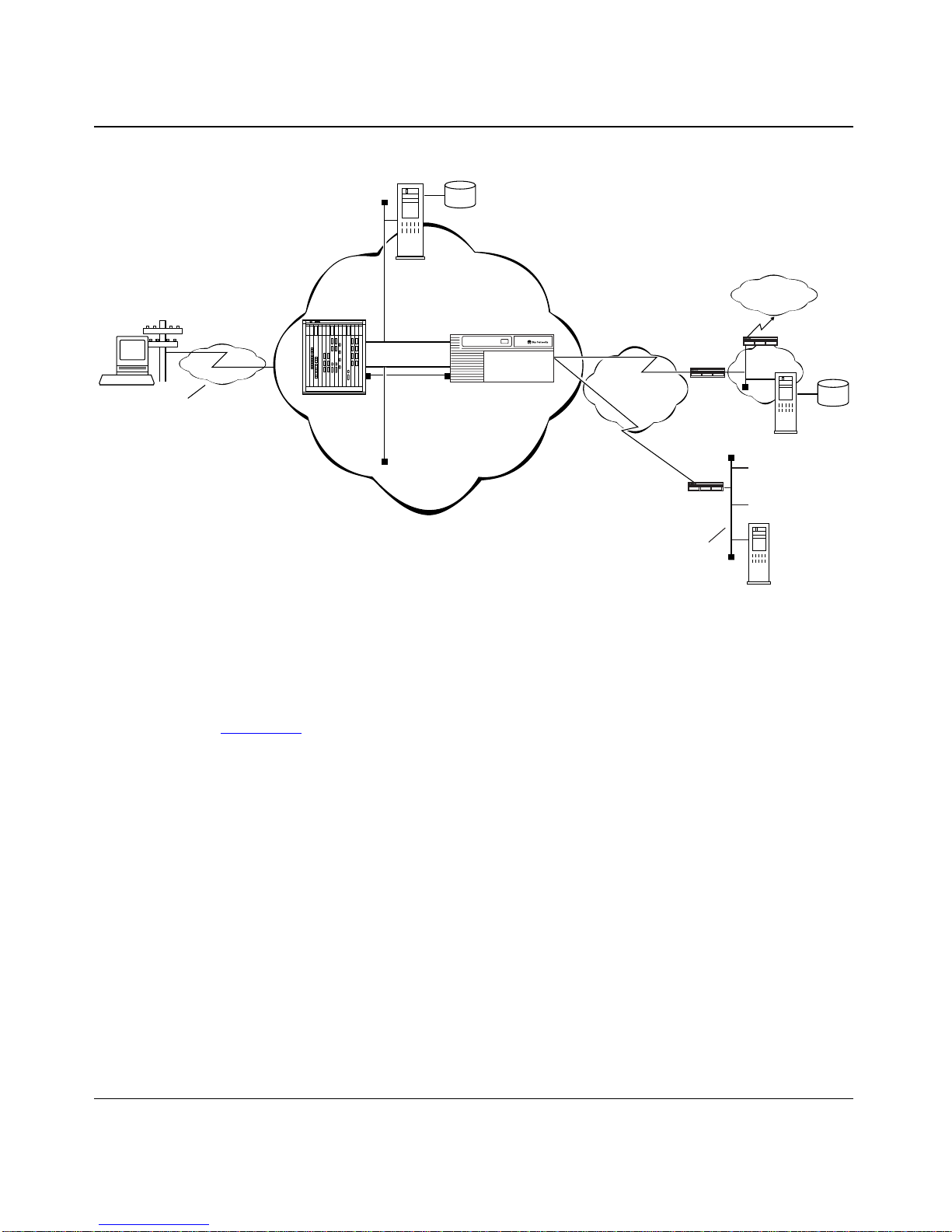
Figure
reality, a Dial VPN service provider’s network might include several remote
access servers to service a variety of dial-in users, and its gateways might serve
different types of networks. This figure may help you visualize the building blocks
when configuring your network. You can configure Dial VPN so that its operation
is transparent to both users and applications. Y ou may find it useful to dra w a map
of your own configuration and label the interfaces with their IP and Data Link
Connection Interface (DLCI) addresses, as appropriate.
1-1 is a simplified illustration of one possible Dial VPN configuration. In
1-2 BayStream Multiservice Software Version 7.2 115623B Rev. 00
Planning for Dial VPN
Tunnel
domain
Service
provider network
data
Third-party
internet
service
provider
network
CPE
CPE
Customer
Network
LAN
Customer
RADIUS
Internet
CPE
Third-party
ISP
RADIUS
server
server
Remote
node
PPP
connection
PSTN
Network
access
server (NAS
TMS /erpcd
server
Gateway
T unnel
Frame Rela y
PVCs
Figure 1-1. Dial VPN Network Providing Connections to Different Destination Types
User
data
DVS0012A
Figure
1-1 shows a Dial VPN service provider network with a gateway that
provides connection services both to a corporate LAN and to a third-party Internet
service provider network. While this figure shows only one tunnel, in reality Dial
VPN creates one tunnel for each dial-in connection.
In this illustration, a user at a remote node can dial in to a corporate or home
network or a third-party ISP by calling a phone number associated with that
destination network. The network access server handles the call. The service
provider’s network uses a standard IP connection between the remote access
server, shown here as a 5393 module in a 5000 MSX chassis, and the gateway. A
frame relay PVC and a static route must exist between the gateway and the
customer premise equipment (CPE) router to provide a path for packets to return
to the remote node.
115623B Rev. 00 BayStream Multiservice Software Version 7.2 1-3

Configuring and Troubleshooting Bay Dial VPN Services
For Bay Networks routers, you must specify an adjacent host and a static route
between the gateway and the CPE, and also between the CPE router and the
remote node. (The adjacent host and static routes do not appear in this diagram.)
See Chapter
detailed description of using adjacent hosts and static routes.
The rest of this guide describes how to install and configure a Dial VPN service
provider network. It also indicates the requirements for the remote node and the
RADIUS server(s), with references to the documentation that explains how to do
the configuration.
2 for an illustration and overvie w-lev el explanation or Chapter 7 for a
Dial VPN Basic Configuration Components
The following sections summarize the elements shown in Figure
essentially provide a checklist of components that you may want to have in your
Dial VPN network.
Remote/Dial-In Node(s)
Remote nodes can be laptop PCs (portable hosts) or dial-up routers, using PPP for
dial-up connections. The portable host must have PPP client software and a
TCP/IP or IPX protocol stack loaded.
Dial VPN supports either dial-up IP or IPX o v er PPP for dial-in PC clients, and IP
over PPP for dial-in routers connected to LANs.
Service Provider Network
The devices that make up the Dial VPN service provider network can be all at the
same site or can be separated by several “hops” within the same network. The Dial
VPN network can consist of a network access server (NAS), a gateway, and a
tunnel management server, as described in the following sections.
1-1. They
Network Access Server
A Network Access Server (NAS) can be a Remote Annex 4000, 6100, or 6300; a
Remote Access Concentrator 8000; or a System 5000 chassis with one or more
Network Access Server modules. Each module is configured with a network
address belonging to the service provider’s address domain.
1-4 BayStream Multiservice Software Version 7.2 115623B Rev. 00

Planning for Dial VPN
The NAS receives and processes calls from remote nodes and routes data to
remote nodes. The NAS can be any of the following:
• 5390 (Remote Annex 4000) -- Asynchronous interface
• 5391 (Remote Annex 6100) -- Single channelized T1 interface to the
PSTN; it can handle up to 24 incoming dial-up connections at 28.8 Kb/s
• 5393 (Remote Annex 6300) -- ISDN PRI interface, which can accept
mixed (synchronous and asynchronous) traffic
• 5399 (Remote Access Concentrator 8000) -- Dual WAN server, which can
support both analog calls and digital calls carried over ISDN
Gateway
The gateway can be an ASN, BLN, BLN-2, BCN, or System 5000 MSX equipped
with a 5380 module running BayStream software.
The gateway connects the Dial VPN service provider’s network and the CPE
router on the remote user’ s home network. The gateway performs con v entional IP
routing functions configured on interfaces connected to the IP network, through
which the remote access servers can be reached.
The gateway is the endpoint of the IP-routed tunnels that transport GRE
encapsulated packets originated by remote nodes and encapsulated by the NAS.
The gateway also connects to the frame relay network between the service
provider’ s netw ork and the user’s home network. The gateway is the data terminal
equipment (DTE) for frame relay PVCs connecting to multivendor RFC
1490-compliant routers on the customer premises, by way of a frame relay
network.
The connection to the frame relay network is through a frame relay User Network
Interface (UNI). The gateway forwards traffic between a remote node and the
corresponding node in its home network by forwarding packets between a frame
relay PVC connecting the UNI to the IP tunnel. Thus, the gateway uses the IP
tunnel and the frame relay PVC as two links through which it can send the user
traffic from one side to the other.
For Dial VPN, the gateway also acts as a RADIUS client to authenticate the
remote user based on information provided from the NAS. The RADIUS client on
the gateway sends an authentication request to the RADIUS server on the home
network, which either grants or denies the request in a message to the gateway.
The gateway then returns this information to the NAS to continue the process.
115623B Rev. 00 BayStream Multiservice Software Version 7.2 1-5

Configuring and Troubleshooting Bay Dial VPN Services
Tunnel Management Server
The NAS retrie v es the tunnel configuration attrib utes from its tunnel management
system (TMS) database residing on the tunnel management server and uses them
to build a tunnel into the customer’ s network. Once the tunnel is open, the user can
be authenticated at the customer’s network. Dial VPN lets you choose between
two methods of tunnel management:
erpcd
-based or RADIUS-only.
• In the
erpcd
-based method, the TMS hosts a database application (the Tunnel
Management System) that controls the IP tunnel establishment attempt from
the NAS. TMS runs on the same UNIX host as the Access Control Protocol
(ACP) software. The NAS and the TMS communicate using the Bay
Networks proprietary Expedited Remote Procedure Call Daemon (
Secure
erpcd
).
• In the RADIUS-only method, a RADIUS server resides on the service
provider site and manages the TMS database. The NAS and the RADIUS
server communicate using IP over the service provider network.
The TMS database lets the NAS query for the addressing information it needs to
construct the IP tunnel. This query is based on the user domain name, and on the
policy and state information of the enterprise customer account when the remote
user dials in. As a Dial VPN network administrator, you must provide the user
domain and tunnel addressing information to the TMS database for each
enterprise customer. Chapter
5 describes the commands you can use to provision
the default TMS database.
Customer/Home/Internet Service Provider Network
erpcd
or
The Dial VPN netw ork interacts with the customer premise equipment (CPE) and
the RADIUS authentication server on the customer’s destination network.
Note:
Dial VPN supports standard ACP logging. A destination network can
provide and maintain its own accounting server, independent of Dial VPN.
Customer Premise Equipment (CPE)
The CPE is a frame relay router that connects to the Dial VPN network by means
of frame relay PVCs. The CPE routes traffic from the remote nodes to hosts on the
home network and from the home network hosts back to remote nodes.
1-6 BayStream Multiservice Software Version 7.2 115623B Rev. 00

Planning for Dial VPN
Enterprise subscribers of this service must configure the CPE router to allow
routing to occur between the remote nodes and the hosts on the home network.
This means that a frame relay PVC, static route, and (if this is a Bay Networks or
other non-Cisco router) adjacent host designation must exist between the CPE and
the gateway router on the Dial VPN network.
RADIUS Authentication Server
The RADIUS server on the customer’s network is a network access security
system. It uses a locally stored and maintained database to authenticate dial-in
user access requests. The RADIUS client of this server resides on the gateway.
The remote authentication server contains all user authentication and network
service access information. The gateway, acting as a RADIUS client, generates a
RADIUS authentication request to the appropriate RADIUS server. This request
contains the user authentication information. The gatew ay sends the request on the
mapped virtual circuit towards the CPE, which recei ves the authentication request
and forwards it to the RADIUS server.
Once the user is authenticated, the RADIUS server grants access to the remote
node by returning an authentication accept packet with RADIUS authorization
information to the gateway through the CPE. The gateway then forwards the user
authorization to the NAS, which initiates an IP tunnel to the gate way using Mobile
IP protocol mechanisms.
Dial VPN Network Planning Worksheet
This section consists of a network planning worksheet. Filling in this information
will give you a handy reference for configuring Dial VPN for your network. As
part of your worksheet, you should also draw a sketch of your network, indicating
the IP addresses of each device and also showing the frame relay PVC, static
route, adjacent host, and DLCI information.
The worksheet contains space for the information you will need when running the
BayStream Quick-Start installation script (
prompts you for network information to connect the router or BayStream platform
to the IP network.
Many steps in the installation script suggest default values. Accept the default
values unless you have a reason to change them.
install.bat
). The installation script
115623B Rev. 00 BayStream Multiservice Software Version 7.2 1-7

Configuring and Troubleshooting Bay Dial VPN Services
Some steps are optional for your network requirements. Use only the portions of
the worksheet that apply to your network. If you don’t run optional features such
as File Transfer Protocol (FTP) or Telnet, your gateway will be more secure and
incur less processing overhead.
At the Dial VPN Service Provider’s Site
Record the equipment you have at your own site. When you have configured the
software, you can add the software information.
•
What device are you using as the dial-in server (NAS)?
(Check all that apply.)
___ Remote Annex 4000/5390
___ Remote Annex 6100/5391
___ Remote Annex 6300/5393
___ Remote Access Concentrator 8000/5399
•
What is the IP address of the network port on the NAS?
_____________________________________________________
•
What type of Bay Networks gateway platform are you using?
___ ASN ___ BCN
___ BLN or BLN-2 ___ 5380 in a System 5000 MSX chassis
•
On the gateway, what is the IP address of
-- the gateway interface to your IP network? __________________________
-- the gateway interface to the frame relay cloud _______________________
•
What is the DLCI of that frame relay interface?
______________________________________________________________
•
If you are using something other than 255.255.255.0 (Standard Class C)
as the subnet mask for that interface, write the mask you are using here.
If you are not using a standard mask, you must configure the interface to
accept RIP Version 2 updates.
______________________________________________________________
1-8 BayStream Multiservice Software Version 7.2 115623B Rev. 00

Planning for Dial VPN
•
List the IP address(es) of the RADIUS client(s) on the gateway.
You can configure one IP address for all clients or one client for each CPE. If
you configure one IP address for all clients, each slot must be configured with
the client. The IP address you specify can be, but is not necessarily, the home
agent’s address.
______________________________________________________________
______________________________________________________________
______________________________________________________________
______________________________________________________________
______________________________________________________________
•
If this is a RADIUS-only configuration, list the IP address(es) of the
RADIUS client(s) on the NAS.
(IP address) ____________________________________________
(IP address) ____________________________________________
•
If this is an
erpcd-based configuration, on what UNIX workstation do the
TMS and the local authentication server (ACP) reside?
(name) __________________________________________________
(IP address) ____________________________________________
• If this is a RADIUS-only configuration, list the IP address of the RADIUS
TMS server.
(name) __________________________________________________
(IP address) ____________________________________________
• What type of Routing Information Protocol (RIP) update packets will
your network advertise/accept?
___ Only RIP 1 ___ Only RIP 2 ___ Both RIP 1 and RIP 2
(OSPF is not supported.)
For Each Destination Site
Record information about each site with which the remote users want to connect.
• Site Name: ____________________________________
• For the frame relay router (CPE) with which the gateway connects:
-- What is its IP address?__________________________________________
-- What is its subnet mask? ________________________________________
-- What is its DLCI? ___________________________________________
115623B Rev. 00 BayStream Multiservice Software Version 7.2 1-9

Configuring and Troubleshooting Bay Dial VPN Services
• If the CPE router is a Bay Networks (or other non-Cisco) router, you
must configure an adjacent host on the CPE router. Fill in the following
information about the adjacent host.
--What is the IP address of the adjacent host (that is, the next-hop router,
in this case, the gateway port)? ___________________________________
-- What is the IP address of the CPE router’s network interface to the
adjacent host? ________________________________________________
-- What is the subnet mask of the adjacent host?
____________________________________________________________
-- What is the physical media access control (MAC) address of the adjacent
host (DLCI number)? __________________________________________
• For the static route between the CPE router and the RADIUS client on
the gateway:
-- What is the IP address of the RADIUS client to which you want to
configure the static route?_______________________________________
-- What is its subnet mask? ________________________________________
• For the static route between the CPE router and the remote node:
-- What is the IP address of the RADIUS client to which you want to
configure the static route?_______________________________________
-- What is its subnet mask? ________________________________________
• What is the IP address of the RADIUS Server on the customer’s home
network?
__________________________________________________________
For Each Remote Node
Record this information for each remote user authorized to dial in to the Dial VPN
network.
• User ID: ____________________________________________________
• For which domain(s) is this user authenticated?
______________________________________________________________
__________________________________________________________
1-10 BayStream Multiservice Software Version 7.2 115623B Rev. 00

Additional Planning Information
Appendix A contains an expanded network planning worksheet that you can use
in determining how to configure the BayStream side of your Dial VPN network.
You may not have enough information yet to complete this table, but if you fill it
in as you go along, it will provide documentation for your network. You may also
find this information useful when changing or troubleshooting your network.
Where to Go Next
For a description of how a packet moves through a Dial VPN network and other
background information that can help you visualize the data flow through the
network, go to Chapter
2.
Planning for Dial VPN
For information about configuring Dial VPN, go to Chapter
3 .
115623B Rev. 00 BayStream Multiservice Software Version 7.2 1-11


Chapter 2
Dial VPN Network Concepts
This chapter describes important Dial VPN network functions to help you
understand the network’ s operation. Among these are how a data packet sent from
a remote node using the point-to-point protocol (PPP) moves through a Dial VPN
service provider’s network to a corporate or “home” network via a frame relay
connection. It also explains how the Dial VPN tunnel forms a path to move data
quickly and efficiently to and from the remote node through the Dial VPN service
provider’s IP backbone network.
Dial VPN uses Mobile IP and Generic Routing Encapsulation (GRE) technologies
to provide a secure pathway for remote users to exchange data with their corporate
home network. Regardless of where a remote node is located, it can dial in to its
Dial VPN service provider and connect to the home network.
What is Tunneling?
Tunneling is a way of forwarding multiprotocol traffic and addresses from remote
nodes to a corporate network through a Dial VPN service provider’s IP backbone
network. GRE is the tunneling mechanism. It takes an incoming packet of any
protocol, wraps that packet’s contents in a GRE packet, then routes the
encapsulated packet over the Dial VPN IP network.
Dial VPN dynamically creates a tunnel when it connects to the remote node’s
home network. The tunnel endpoints are the NAS and the gateway on the Dial
VPN service provider’s network. Once the tunnel is created, packets from the
remote node and the corporate home network flow through the tunnel. Each tunnel
supports one user. The tunnel exists as long as its user remains connected.
115623B Rev. 00 BayStream Multiservice Software Version 7.2 2-1
Configuring and Troubleshooting Bay Dial VPN Services
After establishing a connection, the NAS recei ves a PPP pack et (or payload) from
the remote node. The packet moves from the NAS, through the tunnel to the
gateway, across the frame relay connection, and on to the home network.
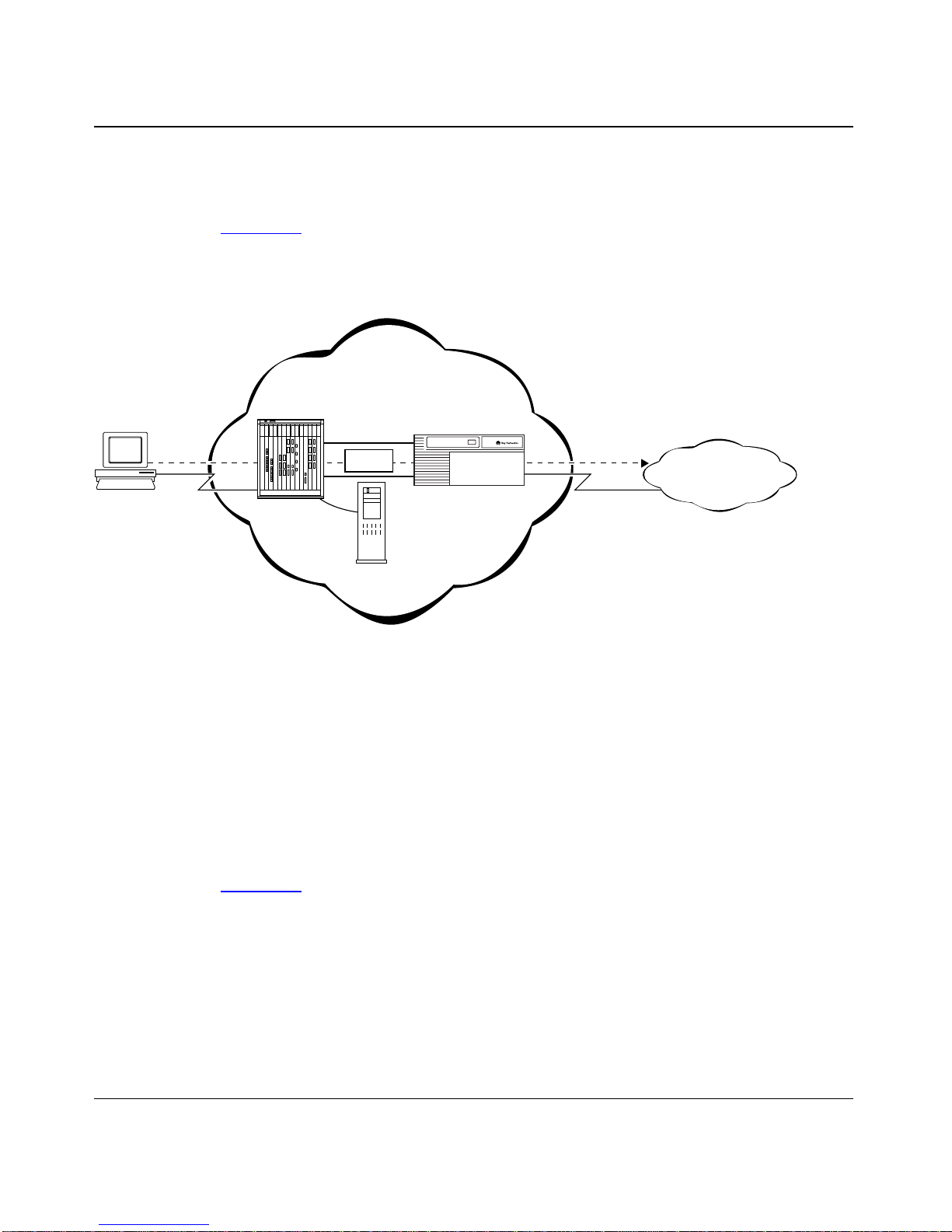
Figure
2-1 shows this progression in an erpcd-based network. In this figure, the
dotted line shows the path of the packet through the tunnel and the BAYDVS
service provider network is the ISP network.
BA YD VS service
provider network
T unnel
Data
Tunnel
management
server
Gateway
Remote
node
PPP
connection
Network
access
server (NAS)
Figure 2-1. The Path of a Packet
Implementing Dial VPN at Your Site
To implement Dial VPN at your site, first connect and configure the components
to ensure proper operation. The steps that follow suggest a possible order for
configuring your network. For detailed information on each of these steps, refer to
Chapters 4 through 7.
FR
connection
Customer
"Home"
network
DVS0001A
Figure
2-2 BayStream Multiservice Software Version 7.2 115623B Rev. 00
2-2 shows a simplified Dial VPN network.
Dial VPN Network Concepts
Remote
node
PPP
connection
Network
access server
(NAS)
Tunnel
domain
data
Service
provider network
T unnel
Tunnel
management server
/Service provider
RADIUS server
Gateway
RADIUS
Client
Figure 2-2. Connecting the Dial VPN LAN and WAN
Build a network, connecting the following:
1.
• Remote Annex or Remote Access Concentrator, serving as the network
access server (NAS)
Frame Rela y
connection
CPE
router
Customer
"Home"
network
User
data
Customer
RADIUS
server
DVS0011A
• Tunnel Management System (TMS) server -- on the UNIX erpcd server
for the erpcd-based solution or on the service provider network RADIUS
server for the RADIUS-only solution.
• Access Control Protocol (ACP) server (only for the erpcd-based solution)
• BayStream platform that serves as the gateway to the remote user’s home
network
This WAN can include intermediate nodes. For installation and startup
information, refer to the hardware documentation for each device. Establish a
remote connection between a gateway on the Dial VPN network and a CPE
router on the home network using frame relay.
2. Install the Tunnel Management System, Annex, and (for the erpcd-based
solution) Access Control Protocol software on the UNIX host that serves
as the load host for the Remote Annex or Remote Access Concentrator
(as described in the Remote Annex or Remote Access Concentrator
documentation).
115623B Rev. 00 BayStream Multiservice Software Version 7.2 2-3

Configuring and Troubleshooting Bay Dial VPN Services
3. Load the operating software onto the Remote Annex or Remote Access
Concentrator from the UNIX load host. Boot the Remote Annex or
Remote Access Concentrator.
For detailed descriptions of the boot procedures, refer to the Remote Annex
and Remote Access Concentrator documentation.
4. Configure the Remote Annex or Remote Access Concentrator software,
as described in Chapter
4, to handle PPP dial-in calls from remote nodes,
determine whether they are tunnel clients, and route them appropriately.
5. For the RADIUS-only solution, configure the RADIUS server on the
service provider network to support the TMS database. Refer to
Chapter 6 for more information.
6. Configure the TMS (including the authentication type) by adding an
entry in the TMS for each domain in the TMS database. Refer to
Chapter
5 for more information.
When configuring the TMS, you can choose either local or remote
authentication. For both the erpcd-based and RADIUS-only solutions, Dial
VPN uses remote authentication; that is, a RADIUS server on the customer’s
home network provides authentication and assigns IP addresses.
7. Configure the gateway, including the RADIUS client, using Site Manager.
Configure the gateway, as described in Chapter
7, with an IP connection to the
Dial VPN network and a frame relay connection to the CPE router on the
remote user’s home network. Configure a RADIUS client on the gateway.
8. Install and configure any intermediate nodes on the WAN.
9. Boot the gateway.
10. Make sure that the remote user’s home network is configured to connect
to the Dial VPN network.
Specifically, ensure that:
• The RADIUS server on the home network is configured to work with the
RADIUS client on the Dial VPN network. If dynamic IP address
allocation is enabled on the gateway, the RADIUS server must have
allocated a pool of addresses for authenticated dial-in users.
2-4 BayStream Multiservice Software Version 7.2 115623B Rev. 00

• The CPE router is configured with a frame relay connection to the Dial
VPN gateway (including a static route and an adjacent host if the CPE
router is not a Cisco device), and a separate but similar frame relay
connection to the RADIUS client on the gateway. Refer to Chapter
more information.
• Any shared information, such as passwords, “secrets,” or phone numbers,
is consistent across the link.
11. Individually test each network component, then test the entire system.
How T unnel Management Works
Tunnel management operates differently on erpcd-based and RADIUS-only
networks, but the end result is the same.
Tunnel Management in an erpcd-based Network
Dial VPN Network Concepts
9 for
For an erpcd-based network, the Tunnel Management System (TMS) runs on the
same host as the Annex (erpcd) and Access Control Protocol (ACP) software.
TMS verifies that the user at the remote node is a Dial VPN user. If the domain
portion of the username exists in the TMS database, ACP increases the number of
current users by one and sends a Grant message to the Remote Annex. The Grant
message contains the tunnel addressing information needed to send a packet from
the remote node to the home network.
The Grant message contains the following information, which is stored in the
TMS database. For a Dial VPN user, the NAS sends this information to the
RADIUS client on the gateway, which in turn sends an authentication and address
request to the RADIUS server on the remote node’s home network. When the
RADIUS server responds, authenticating the user, the NAS establishes the tunnel.
• Remote node’s domain name
• DNIS -- for 6300/5393 and 8000/5399 platforms, this is the called number;
for other platforms, it’s 0 (zero)
Note: The default value for DNIS is 0 as well. The Remote Annex
administrator can change this value.
115623B Rev. 00 BayStream Multiservice Software Version 7.2 2-5

Configuring and Troubleshooting Bay Dial VPN Services
• Home agent’s IP address on the gate way (the IP address of the gate way end of
the IP tunnel)
• Current number of users
• Type of connection between the gateway and the CPE router on the remote
node’s home network
• Primary and secondary RADIUS server IP addresses
• Authentication protocol information
Tunnel Management in a RADIUS-only Network
The RADIUS-only solution integrates the TMS database functions into the
RADIUS server that resides on the service provider network. This RADIUS
server recognizes the format of the VPN identifier in the user name and returns
tunnel information to the NAS. The NAS uses the tunnel information to establish
a connection to the gateway. Once the connection is up, the user authentication
information is forwarded to the indicated authentication server.
Refer to Chapter 5 for more information about the contents of the TMS database.
How the TMS Database Works
The TMS database (by default, UNIX ndbm) resides in the Tunnel Management
Server , which resides on the service provider’s network. The main function of this
database is to verify the username (or domain) information supplied by the NAS.
It also supplies the NAS with the tunnel addressing information (in the Grant
message) it needs to create a tunnel for a remote user . The Dial VPN administrator
enters the domain information and the tunnel addressing information into the
database as part of the TMS configuration process.
When TMS receives a lookup request from the NAS, it parses the username into
the user and domain name and DNIS and creates a Domain/0 or Domain/DNIS
key. The TMS database uses this key to find a match in the database with the
supplied username. If the key matches an existing entry, TMS checks to make sure
that the maximum number of users is less than the configured maximum. If so,
TMS sends a Grant message to indicate that the user is a Dial VPN user. The
Grant message contains the tunnel addressing information.
2-6 BayStream Multiservice Software Version 7.2 115623B Rev. 00

Since ndbm does not have a locking feature, Bay Networks has implemented
application-level locking to pre v ent users from updating the database while others
are using it. The lock files are created in the install directory.
Note: Both the erpcd (Expedited Remote Procedure Call daemon) and
tms_dbm utilities use a common library of functions (in tms_lib.c) to access
the database. If you replace the database and provide access to it through the
same library function interface, as required, the same commands will work.
You can replace the default database engine with a standard UNIX relational
database, such as Sybase, Informix, or Oracle, or with one you have created
yourself. For information on how to replace the default TMS database, contact
the Bay Networks Technical Solutions Center.
Dynamically Allocating IP Addresses
Dial VPN lets you choose between tw o methods of dynamic IP address allocation,
one using a Dynamic Host Configuration Protocol (DHCP) server, and the other
using the RADIUS server. The following sections describe each of these methods.
Dial VPN Network Concepts
Using DHCP for Dynamic IP Address Allocation
This method requires that a DHCP server reside on the home/corporate network.
This server communicates with a DHCP client proxy residing on the BayStream
gateway. The server dynamically allocates an IP address for a dial-in user when
the client proxy requests one.
Based on RFC 1541 and its extensions, DHCP not only provides a scalable
method of dynamically allocating IP addresses to remote users, it also provides a
way of managing the IP addresses dynamically assigned to dial-in users. The Bay
Networks implementation of DHCP supports
• Standard DHCP operation, as described in RFC 1541
• Interoperation with standard DHCP servers
• Use of both primary and secondary DHCP servers
• DHCP leases with as many servers as there are tunnels
• Both Dial VPN (tunneled) and non-tunneled users
115623B Rev. 00 BayStream Multiservice Software Version 7.2 2-7

Configuring and Troubleshooting Bay Dial VPN Services
• Getting IP addresses through either the local or the remote DHCP client
proxy, in addition to other methods that Dial VPN supports, depending on
how the Dial VPN subscriber is provisioned
How DHCP Works
DHCP implements the concept of IP address leasing. An authenticated, dial-in
user receives an exclusive right to use an assigned IP address for a specific,
configurable period of time, called a “lease.” When this lease expires, the DCHP
client proxy can renew the lease or let it lapse, returning the IP address to the pool.
DHCP lets a network manager designate a range of assignable IP addresses
without requiring that each IP address be tied to a specific MAC (hardware)
address. The DHCP server leases an IP address to each dial-in user and
dynamically maintains a table that links a user’ s IP and MA C addresses. F or users
who need a fixed IP address, a network manager can also specify a permanent
assignment. A single N AS can communicate with and maintain DHCP leases with
up to as many DHCP servers as there are ports on the NAS (up to 48 or 62,
depending on the model).
When a remote user dials in to a remote access server (NAS), Dial VPN performs
the usual authentication functions. When the gate way returns the Mobile IP (MIP)
authentication response to the NAS, however, the NAS sends the gateway a MIP
dynamic address allocation (DAA) request. The gateway sends a DHCP discover
request to the DHCP server on the home network, and the server responds with an
acknowledgment (ACK) if the request is successful. The gateway then sends the
MIP DAA response back to the NAS, and the rest of the negotiation proceeds as
usual. Figure
2-3 shows the entire process.
2-8 BayStream Multiservice Software Version 7.2 115623B Rev. 00

Dial VPN Network Concepts
Remote
Node
LCP negotiation
CHAP initiation
CHAP completion
NCP negotiation
Connect
RAS TMS Gateway
Auth/Info Req
Grant w/info
MIP authentication request
MIP authentication response
MIP DAA request
MIP DAA response
MIP registration request
MIP registration response
Open Communication
RADIUS
Auth Req
Auth Resp w/info
Acct Start
DHCP discover/ request
Server
Acct Response
DHCP response/ack
Accounting
Server
DHCP
Server
Local
Node
Disconnect
Terminate msg
MIP terminate request
MIP terminate response
Acct Stop
Acct Response
Addr Rel
Response
DVS0009B
Figure 2-3. DHCP Operational Timeline
115623B Rev. 00 BayStream Multiservice Software Version 7.2 2-9

Configuring and Troubleshooting Bay Dial VPN Services
Using RADIUS for Dynamic IP Address Allocation
Each dial-in user retains a unique IP address for the duration of the dial-in session.
Dial VPN relies on the BSAC RADIUS server on the user’s home network to
provide those addresses, allocating them either statically or dynamically. In static
allocation, the RADIUS administrator assigns specific addresses for specific
users. In dynamic allocation, the administrator allocates a pool of IP addresses
from which the RADIUS server selects an address to assign.
The BayStream administrator configures the IP address of a RADIUS server that
uses dynamic address allocation and also enables dynamic address allocation on
the gateway for that server connection.
When a user dials in to a network using dynamic address allocation, RADIUS
authenticates the user and assigns an IP address from the pool. That user has
exclusive use of that address for the duration of the connection. RADIUS also
maintains a database of assigned addresses. This prev ents duplicate assignments if
the server fails.
When the connection ends, the released IP address returns to the pool, at the end
of the assignment queue.
To implement dynamic IP address allocation, Dial VPN requires that the program
BaySecure be installed on the RADIUS server on the customer’s home network.
BaySecure is a robust implementation of the draft IETF RADIUS specification,
compliant with RFC 2058 and RFC 2059.
For information about BaySecure, contact your Bay Networks sales
representative.
Starting the Connection
When a user at a remote node dials a Dial VPN service provider, the NAS first
determines whether this is a tunnel candidate. If so, the NAS first accesses the
TMS database and contacts the gateway, which starts the authentication process.
The gateway gets an IP address from the RADIUS server on the user’s home
network, and the Remote Annex builds a tunnel to a gateway and starts sending
the GRE-encapsulated packets. The process involves the following steps.
1. A user at a remote node dials the phone number of a Dial VPN service
provider. The user also enters user information, as required by the
connection process.
2-10 BayStream Multiservice Software Version 7.2 115623B Rev. 00

Dial VPN Network Concepts
User information usually is a user name and a password.
2. The remote node sends a PPP packet to start the connection process.
3. The NAS receiv es the data packet and passes the username to the TMS on
the Dial VPN ser vice pr o vider’s network to determine how to process the
packet.
For Dial VPN, the username must contain one “at” sign (@), followed by at
least one period (.) and at least a 3-character extension. For example, the
username can be lee@abc.com. In this example, lee is the username part that
the NAS uses for authentication. The string @abc.com is the domain name
part that Dial VPN uses to look up this user’s entry in the TMS database.
If TMS finds a match in its database for both the user and domain names, it
determines that this user is a Dial VPN user and a candidate for tunnel
creation. TMS then checks that the number of current connections does not
exceed the maximum number of users allowed.
Note: The system administrator can change the default requirements for the
Dial VPN username format as needed.
If the user is not a tunnel candidate, the NAS first treats the request as a proxy
RADIUS request and attempts to authenticate this user in the usual way . Refer
to the description of proxy RADIUS in the BSAC Administration Guide for
your platform.
4. If the dial-in request is a tunnel candidate, the NAS starts the
authentication process and builds a tunnel.
Once it has determined that this request is a tunnel candidate, TMS tells the
NAS to contact the gateway for remote authentication, where authentication
and address allocation will take place. For a giv en domain, authentication and
address allocation can take place locally, using ACP (in an erpcd-based
network), or remotely, using RADIUS and DHCP on the customer’s netw ork.
If the request is not a tunnel candidate, the NAS uses local (instead of remote)
authentication.
The NAS recei v es the remote node’s address, the source of which depends on
the type of authentication and the type of IP address allocation.
115623B Rev. 00 BayStream Multiservice Software Version 7.2 2-11

Configuring and Troubleshooting Bay Dial VPN Services
Note: TMS may deny a tunnel request for a number of reasons; for example, if
the maximum number of users has been reached, if TMS does not find a match
for the domain name in its database, or if the authentication request fails. If the
tunnel request is denied, the connection between the NAS and the remote node
is dropped.
5. The RADIUS client (in the gateway) sends a request to the RADIUS
server to authenticate the remote user.
During remote authentication, the RADIUS authentication server on the
corporate home network verifies that the remote node is authorized to access
the home network and determines which network services the remote node is
allowed to use.
6. The DHCP or the remote RADIUS server assigns an IP address and
includes that address in the reply.
If the home network is configured to assign IP addresses dynamically using
DHCP, the DHCP server selects an IP address from its pool and issues the end
user a renewable “lease” on that address. Alternatively, the DHCP
administrator may assign a fixed IP address to particular users. In either case,
the DHCP server returns the assigned IP address in its reply to the gateway.
If the home network is configured to assign IP addresses using RADIUS,
either statically or dynamically, the RADIUS server performs the address
allocation. If the RADIUS administrator has allocated a pool of assignable IP
addresses for dial-in users, and if the RADIUS client on the gateway is
configured for dynamic IP address assignment, the RADIUS server assigns an
address from that pool. Alternatively, the RADIUS administrator may have
assigned a specific address for that particular user . In this case, RADIUS uses
that assigned address. The RADIUS server reserves the assigned IP address
for that user until the session terminates.
7. When authentication and address allocation are complete, the N AS starts
sending packets from the remote node to the gateway via the newly
created tunnel.
2-12 BayStream Multiservice Software Version 7.2 115623B Rev. 00

A Day in the Life of a Packet
The next sections explain how a packet moves through a Dial VPN network and
returns to the remote node. Figure
As the packet moves from the remote node to the home network, different pieces
of the Dial VPN network must encapsulate (add) and decapsulate (strip off) the
protocol-specific envelope around the data packet.
Dial VPN Network Concepts
2-4 shows the process.
115623B Rev. 00 BayStream Multiservice Software Version 7.2 2-13

Configuring and Troubleshooting Bay Dial VPN Services
PPP packet
Flag FlagAddress Control Protocol Data FCS
GRE packet
CRKSs T FlagControl V ersion Protocol
Frame Relay packet
Opening
Flag
Address Information FCS Data
Control
Remote node
Remote annex
Type
Gateway
Data Tunnel ID
Closing
Flag
Figure 2-4. Packet Encapsulation and Decapsulation Process
2-14 BayStream Multiservice Software Version 7.2 115623B Rev. 00
CPE Router
Data packet moves onto home network
DVS0003A

How a Packet Moves Through a Dial VPN Network
A data packet moves from a remote node to the Dial VPN service provider’s
network through a tunnel created for the remote node to a gateway, which sends
the data to the remote user’s home network through a frame relay connection.
Here are the steps involved in this process.
1. The remote node sends a PPP packet to the NAS to establish a
connection.
The PPP packet contains flag fields to indicate the beginning and end of a
frame, an address field to indicate the device that originated the frame, a
control field to indicate the type of frame (information or administrative), a
protocol field that indicates the operative network layer protocol, the data, and
the Frame Check Sequence that shows the sequence order of the frame. Refer
to the BayStream manual, Configuring Dial Services, for more information
about the PPP packet.
2. The NAS strips off the PPP protocol-specific fields and encapsulates the
data into a GRE packet. The GRE packet can mo ve through the IP tunnel
to the gateway.
Dial VPN Network Concepts
The GRE packet contains checksum information and flag bits to indicate that
a routing and a key field are present; a control field to indicate the type of
frame; a tunnel flag to indicate that there is a tunnel ID present; a version field
to indicate the version of IP (or IPX) running on the Internet; the protocol type
used (IP or IPX); the tunnel identifier; and the original data from the data
packet. Refer to IETF RFC 1701 or RFC 1490 for more information about the
GRE packet.
Note: The checksum, control, tunnel flag, and version fields should be set to
zero.
3. The gateway decapsulates the GRE packet information and puts the data
into a frame relay packet.
115623B Rev. 00 BayStream Multiservice Software Version 7.2 2-15

Configuring and Troubleshooting Bay Dial VPN Services
The frame relay packet contains flag fields to indicate the beginning and end
of a frame; an address field to indicate a logical point that defines the data link
between the gateway and the home network and the terminal endpoint
identifier; a control field to indicate the type of frame; an information field
that contains the data to set up the link; a cyclical-redundancy check field; and
the original data from the data packet. Refer to the BayStream manuals for the
type of link you are configuring (Configuring F rame Relay Switching Services
or Configuring Frame Relay Services for IP Routing) for more information
about the frame relay packet.
4. The gateway sends the frame relay packet to the CPE router on the
corporate home network.
5. The CPE router decapsulates the frame relay inf ormation and routes the
data to the intended recipient on the home network.
How a Packet Returns to the Remote Node
To send packets from the home network to a remote node, Dial VPN essentially
reverses the process described in the previous section. The tunnel ensures that
packets from the corporate home network reach the remote node, regardless of
where it is located. The Dial VPN gateway is responsible for intercepting and
forwarding packets to the remote node using a care-of address that is specified to
the gateway during the connection process. This address, which is usually the
address of the Dial VPN Remote Annex, is the IP address of the other endpoint of
the tunnel. When the gateway encapsulates the frame relay packet into a GRE
packet, it includes the care-of address.
Figure
2-5 shows a simplified view of how a data packet moves from the home
network to a user at a remote node through an erpcd-based network.
2-16 BayStream Multiservice Software Version 7.2 115623B Rev. 00
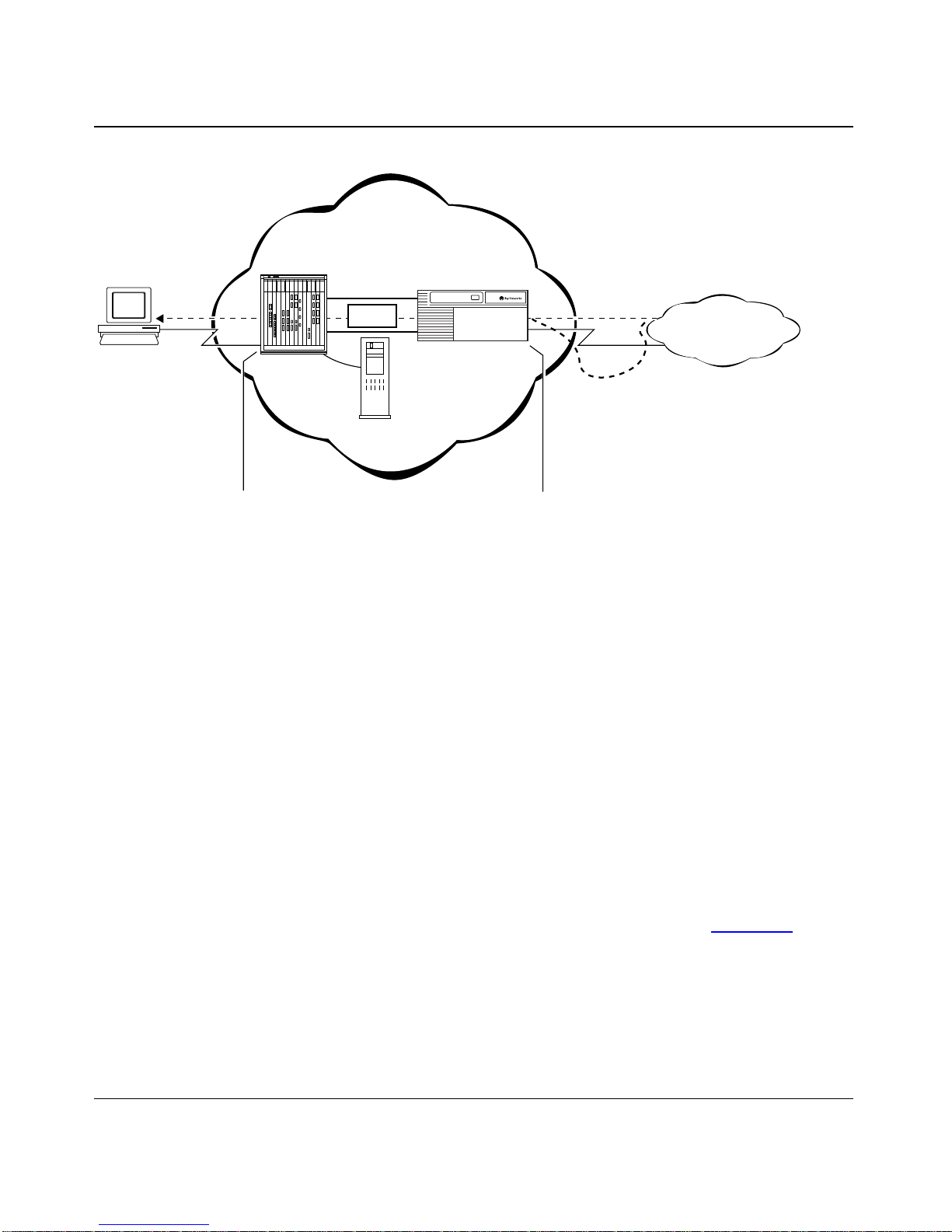
Remote
node
PPP
connection
Network access
server (NAS)
Service
provider network
T unnel
Data
Tunnel
management
server
Gateway
Dial VPN Network Concepts
Frame Rela y
connection
Customer
"Home"
network
Static routes
The gateway sends the packet to the
Remote Annex's
Remote Annex decapsulates the GRE
information and then encapsulates the
data with PPP information. The Remote
Annex sends the PPP packet to the
remote node.
care -of address
. The
The packet moves from the CPE
router to the gateway via static routes.
The gateway decapsulates the Frame
Relay information and then encapsulates
the data with GRE information. The gateway
sends the GRE packet to the care of address.
Figure 2-5. Sending a Packet to a Remote Node
The data packet travels from the home netw ork to the remote node using a similar
process of encapsulation and decapsulation to respond to the format required at
various points throughout the Dial VPN network. The differences are:
• The data packet must return from the CPE router on the home network to the
gateway on the Dial VPN network via static routes.
• If the CPE router is a Bay Networks (or similar) router, a nonexistent,
“dummy” adjacent host must be configured on the same IP subnet as the
frame relay interface of the CPE router. This fulfills an addressing format
requirement, but has no effect on the actual packet routing. Figure
the static routes used to return data from a home network to a gateway on the
Dial VPN network.
DVS0013A
2-6 shows
• The gateway sends the GRE packet to the remote node’s care-of address on
the NAS, and the NAS forwards the packet to the remote node.
115623B Rev. 00 BayStream Multiservice Software Version 7.2 2-17
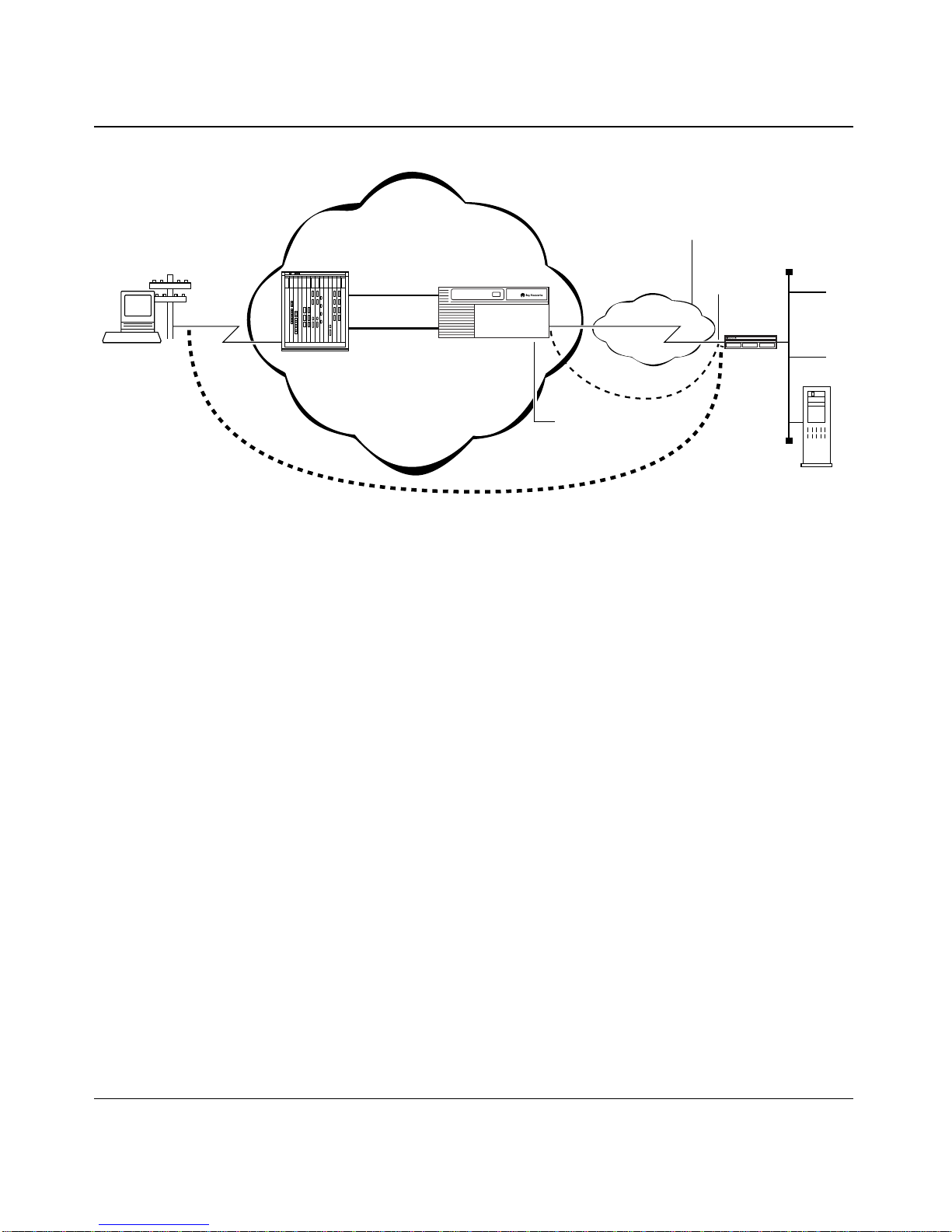
Configuring and Troubleshooting Bay Dial VPN Services
1.1.1.2
Adjacent host/
next hop
Frame Relay
PVC
Static route
Dial-up
user
3.1.1.X
Remote
Annex
BayDVS service
provider's network
Tunnel
Gateway
RADIUS
client
DLCI = 101
2.2.21
Frame Relay
port on gateway
Static route
Figure 2-6. Static Routes from a CPE Router to a Dial VPN Gateway
Data packets move back and forth between the remote node and the home network
through the established tunnel until the remote node disconnects from the Dial
VPN network or an error occurs. When either situation occurs, Dial VPN tears
down the tunnel.
3.1.1.0
Home/
corporate LAN
1.1.1.1
CPE
RADIUS
server
DVS0007A
When Does Dial VPN Tear Down the Tunnel?
Dial VPN tears down the tunnel when any of the following situations occurs:
• The remote node using that tunnel disconnects
• Either the NAS or TMS is not operating properly
• Tunnel renewal fails
• The administrator terminates the user connection
If the NAS fails, all tunnel users are disconnected and the active user counts are
decremented. Howev er, there is no quick way to determine when a NAS fails. The
logging connection may not be reset until after new tunnel users have connected.
When a NAS starts, one of the first things it does is open its ACP-logging
connection. When a new logging connection opens, TMS decrements the
2-18 BayStream Multiservice Software Version 7.2 115623B Rev. 00

Dial VPN Network Concepts
appropriate counts for each domain that had a user connected to the NAS. If this is
the first time the NAS has come up, then there will be nothing to decrement.
Note: If you enter the reset security command, a new user who tries to make
a connection with the NAS causes the maximum number of users count to
decrement, even though users with existing connections are still connected.
This means that the maximum number of users count may be exceeded. As
users with existing connections disconnect, the count will synchronize and
correspond to the actual number of users connected.
If the TMS fails, a NAS can detect the failure through the failure of the logging
connection. The NAS falls back to secondary servers, if any. Unless the database
is shared by the TMS servers, the count of current users is lost.
If the TMS database runs out of disk space while tms_dbm is running, the user
sees an error message. The error message may not state what caused the error. If
there is a shortage of disk space and erpcd cannot create a lock file or add a NAS
to the TMS database, TMS generates a syslog message and the user cannot make a
connection to the NAS.
115623B Rev. 00 BayStream Multiservice Software Version 7.2 2-19


Chapter 3
Setting Up a Dial VPN Network
Installing and configuring a Dial VPN service provider network involves several
phases, some of which you may already have done. You must:
• Plan the network.
• Install and connect the hardware.
• Install and configure the software.
• Verify that the elements outside the Dial VPN network, specifically the
remote RADIUS server, the CPE, and the remote dial-in nodes, are properly
configured.
• Power up, test, and troubleshoot your network.
Dial VPN Network Hardware Requirements
To set up a Dial VPN network, you must install at least the following hardware:
• A network access server, which can be a Remote Annex 4000, 6100, or 6300;
a Remote Access Concentrator 8000; or a corresponding 5390, 5391, 5393, or
5399 processor in a 5000 MSX chassis.
• A UNIX host for the TMS and the ACP server if this is an erpcd-based
network.
• A Bay Networks BayStream gateway, which can be an ASN, BLN, BLN-2, or
BCN, or a 5380 device mounted in a 5000 MSX chassis.
• An IP Ethernet network connecting all of the above. This network can be as
short as the distance between two blades in a 5000 MSX chassis or can be a
wide area network with several hops between the edge nodes.
• Cables, connectors, and jumpers appropriate to the devices in your network.
115623B Rev. 00 BayStream Multiservice Software Version 7.2 3-1

Configuring and Troubleshooting Bay Dial VPN Services
Where to Find Hardware Installation Information
Since a Dial VPN service provider network can consist of many pieces, you’ll
need to refer to several pieces of documentation for the installation information.
able 3-1 lists where to look for that information.
T
Table 3-1. Where to Find Installation Information
For this information Look here
Installing and starting the BayStream
platform
Troubleshooting BayStream hardware
problems
Preparing the platform for configuration
management by running the
Configuring a BayStream platform
Troubleshooting other BayStream problems
Installing the Remote Annex or Remote
Access Concentrator and adding or
replacing hardware
Overview of Remote Annex or Remote
Access Concentrator software and startup
options
Starting a Remote Annex or Remote
Access Concentrator
Configuring a Remote Annex or Remote
Access Concentrator
Troubleshooting Remote Annex or Remote
Access Concentrator hardware problems
install.bat
file
The installation manual for your BayStream
platform
Troubleshooting and Testing
Configuring an Interface for Network
Management
Getting Started with Site Manager
Troubleshooting and Testing
The installation manual for the specific
Remote Annex or Remote Access
Concentrator that you are installing
Remote Annex Administrator’s Guide for
UNIX
or
Remote Annex 6300 Supplement
to the Remote Annex Administrator’s Guide
for UNIX
Quick Start Guide for Remote Access
Concentrators, Managing Remote Access
Concentrators Using Command Line
Interfaces,
Concentrators Using Annex Manager.
and
Managing Remote Access
Configuring BaySecure Access Control
Configuring and troubleshooting the
Dial VPN network
3-2 BayStream Multiservice Software Version 7.2 115623B Rev. 00
BaySecure Access Control Administration
Guide
appropriate to your platform
This guide

In addition, you must ensure that the CPE router at the destination site
(corporate/home network or third-party Internet service provider) has access to
frame relay. Given that, there should be no need to upgrade or modify the CPE.
For remote authentication, the destination site must also have a RADIUS server
on the network.
A Remote Annex 4000 or 5390 also requires one asynchronous modem for each
port to handle incoming calls.
Your network may include more than one network access server and gateway,
depending on the needs of your installation. The same installation and
configuration principles, however, apply to each element. Refer to the installation
instructions in the hardware installation guide for the specific Remote Annex or
Remote Access Concentrator being installed.
Additional Configuration Considerations
Setting Up a Dial VPN Network
You must also load the boot image software and configure the:
• Modem ports
• Individual and group security access rights for dial-in
• Remote routing to other networks
• Activity log files
Configuring the IP Interface
To configure the initial IP network interface on the gateway, complete the
Quick-Start procedure described in the BayStream manual, Configuring an
Interface for Network Management. In this procedure, you enter commands
through a PC (in VT100 terminal emulation mode) or an ASCII terminal.
Complete the following steps:
1. Set the operating parameters of the ASCII console as follows:
• Baud rate = 9600
• Stop bits = 1
• Parity = none
• Data bits = 8
115623B Rev. 00 BayStream Multiservice Software Version 7.2 3-3

Configuring and Troubleshooting Bay Dial VPN Services
2. Connect the cable from the ASCII console to the gateway.
BCN and BLN routers have a 25-pin male console port. ASN routers have a
9-pin male console port. Refer to the installation guide that came with your
BayStream platform for more information.
3. Power on the BayStream platform to complete the internal diagnostics
and startup.
When the BayStream platform boots, the screen displays the Technician
Interface
Login prompt. Configuring an Interface for Network Management
describes the Quick-Start procedure in detail.
Configuring the Dial VPN Network Software
You install the software and configure each of the Dial VPN software components
separately:
• Install and configure the software on the Remote Annex or Remote Access
Concentrator.
• Install and build the Tunnel Management database (and, for an erpcd-based
network, the Access Control Protocol database) on the server(s).
• Install and configure BayStream software on the gateway (BayStream
platform) using Site Manager.
• Install and configure Mobile IP and the RADIUS client software on the
gateway using Site Manager.
• Ensure that the CPE router is configured for frame relay.
• Ensure that the remote nodes (dial-in PCs or dial-up routers) are configured to
use PPP.
The following chapters describe how to do this installation and configuration,
referring you to the appropriate product-specific documentation, when necessary.
3-4 BayStream Multiservice Software Version 7.2 115623B Rev. 00

Setting Up a Dial VPN Network
Configuring Local Authentication Using the ACP
Dial VPN relies on the remote authentication (RADIUS) server at the destination
site to authenticate the dial-in users. If you are configuring an erpcd-based
network and you want to use local authentication (that is, within the Dial VPN
service provider network), the acp_regime file must contain
You must also configure the Access Control Protocol (A CP) authentication serv er ,
as follows:
1. Using CHAP for local ACP authentication, create an ACP file called
acp_userinfo (by default in the /usr/annex directory):
acp_userinfo for CHAP
The following is a sample entry for the acp_userinfo:
user sample1
chap_secret annex
end
<path> /acp_passwd.
2. Similarly, if you are using PAP, you create a file called acp_passwd for
PAP:
acp_passwd for PAP
If you are using CHAP as your authentication protocol, you need to set the
PAP password only if you enable CHAP with PAP fallback. The following
sample entry shows an encrypted acp password for PAP:
sample1:IQ3Qo0HXrsUoM:501:500:& sample1:/users/user1:/bin/csh
The user cannot enter a password directly. To enter a password, use the
ch_passwd utility. The acp_password file uses the same format as the
/etc/passwd file.
3. Now set the dialup addresses in the acp_dialup file for IP and IPX
addresses, as shown in the following sample entry:
sample1 * 128.128.129.181<---- IP Address
sample1 * 013ABC0:~<---- IP Network Address
For IPX, use the network and node address combination; for example,
0013ABC0:001234560000
The first 8 hexadecimal digits represent the IPX network address; the last 12
hexadecimal digits represent the IPX node address.
115623B Rev. 00 BayStream Multiservice Software Version 7.2 3-5

Configuring and Troubleshooting Bay Dial VPN Services
ACP security includes:
• acp_userinfo information
• acp_password information
• Security for CHAP and PAP
• acp_dialup information for IP and IPX addresses
For a complete description of ACP security, refer to the following documentation:
• Remote Annex Administrator’s Guide for UNIX
• Remote Annex 6300 Supplement to the Remote Annex Administrator’s Guide
for UNIX.
• Managing Remote Access Concentrators Using Command Line Interfaces.
3-6 BayStream Multiservice Software Version 7.2 115623B Rev. 00

Chapter 4
Configuring the Remote Annex
This chapter describes how to use the command line interface (CLI) commands to
configure a Remote Annex or Remote Access Concentrator device as a network
access server for Dial VPN. This should get your NAS up and running, but for
details regarding your specific device, refer to the documentation for the particular
model you are configuring, as shown in T
able 4-1.
Table 4-1. Where to Find Configuration Information
For information on Refer to this document
Using the Annex Manager to configure the
Remote Annex
Using the Annex Manager with Remote
Access Concentrators
Remote Annex configuration and
administration procedures, and a detailed
description of all na and admin commands
and parameters
Remote Access Concentrator configuration
and administration procedures
Appendix C, “Using Quick2Config and
Annex Manager.”
Managing Remote Access Concentrators
Using Annex Manager.
• Remote Annex Administrator’ s Guide for
UNIX
• Remote Annex 6300 Supplement to the
Remote Annex Administrator’ s Guide for
UNIX
• Quick Start Guide for Remote Access
Concentrators
• Managing Remote Access
Concentrators Using Command Line
Interfaces
• Managing Remote Access
Concentrators Using Annex Manager
You configure the Remote Annex or Remote Access Concentrator by attaching a
PC in terminal emulation mode or an ASCII terminal to the console port of the
device.
115623B Rev. 00 BayStream Multiservice Software Version 7.2 4-1

Configuring and Troubleshooting Bay Dial VPN Services
Installing and Configuring the Annex Software
This section is an overview of the installation and configuration process,
highlighting areas of particular concern. Subsequent sections describe the process
in more detail and include more extensive examples.
Note: To facilitate troubleshooting, test each element of your system after you
configure it and before proceeding to the next phase of the configuration.
1. Install the Annex Software.
This is a standard installation using the installation script supplied for Dial
VPN, as described in the documentation for the particular device you are
installing.
As part of the hardware installation, you may have issued ROM Monitor
commands through a terminal connected to the console port located on the
Remote Annex. These commands let you set a subset of the configuration
(EEPROM) parameters, including the unit’s IP address, required for booting
the Remote Annex.
You can also specify parameter values that are required if the network
configuration differs from the default values. Refer to the hardware
installation guides for the Remote Annex or Remote Access Concentrator
being installed for the list of the ROM Monitor commands and their default
values.
2. Boot the Annex software (standard installation).
The Annex (used generically here to indicate either the Remote Annex or the
Remote Access Concentrator) gets its operational code by downloading it
over the network from (among other sources) a UNIX host that runs Annex
file server software. The Annex boots each time it is powered up and
whenever it receives a
boot command. You specify the source of the boot
image by setting the preferred load host.
3. Set up the dial-in port on the Annex for dial-in, and enable ACP or
RADIUS (BSAC) security for PPP on all ports.
Configure security on the Annex using either ACP (for an erpcd-based
network) or BSAC (for a RADIUS-only network) configure the dial-in ports.
To display the current port settings, enter:
4-2 BayStream Multiservice Software Version 7.2 115623B Rev. 00

Configuring the Remote Annex
show port ppp
To change a particular setting, enter the set port command along with the
parameters you want to change.
The settings relevant to Dial VPN are:
set port slip_ppp_sec y
set port ppp_sec_prot <chap or pap>
set port address_origin auth_server
The slip_ppp_security parameter controls dial-in PPP access and use of ACP
or RADIUS for PPP and protocol security. The
ppp_sec_protocol parameter
specifies the local authentication protocol; in this case, CHAP. A client dialing
in has to get a remote IP address. For Dial VPN, the
must be set to
auth_server. For information on BSAC security, refer to the
address_origin parameter
BaySecure Access Contr ol Administr ation Guide.
For information on the settings of the remaining port parameters, refer to:
• Remote Annex Administrator’s Guide for UNIX
• Remote Annex 6300 Supplement to the Remote Annex Administrator’s
Guide for UNIX
• Managing Remote Access Concentrators Using Command Line
Interfaces.
Set the primary preferred security host to the address of the primary TMS
server. You can also designate the secondary TMS server (if any) as the
secondary preferred security host. Accept the default value if the optional
secondary security host is not in use.
Enable security on the Annex, but disable the security broadcast feature.
Setting the security broadcast parameter to N ensures that the security
information comes from one of the defined TMS servers.
For all Remote Annex models, the mode on the dial-in port can be set to
auto_detect. For Remote Annex models 6100/5391and 6300/5393, and for
or
PPP
Remote Access Concentrator 8000/5399, enter the following configuration
command sequence from the
set annex enable_security y
set annex pref_secure1_host <ip address of TMS host - ACP or BSAC>
set annex pref_secure2_host <ip address of secondary security host>
set annex security_broadcast N
set annex auth_protocol <acp or Radius>
na or admin prompt:
115623B Rev. 00 BayStream Multiservice Software Version 7.2 4-3

Configuring and Troubleshooting Bay Dial VPN Services
##
# include the following command for erpcd-based networks
set port address_origin auth_server
#
set port mode auto_detect
set port type dial_in
##
set port slip_ppp_security y
set port ppp_security_protocol chap
# This could be chap, pap, or pap-chap.
The Remote Annex 4000/5390 contains ports that are used as serial ports or
analog modem ports. In addition to configuring parameters common to all
Annexes, you must also configure port level parameter parameters specific to
analog modems. The value for the type of modem parameter is acquired from
the modems.annex file (default path /usr/spool/erpcd/bfs). You can list the
modems in the modems.annex file using the
Annex.
On a Remote Annex 4000/5390, enter the following configuration command
sequence from the
na or admin prompt:
modem -l command on the
set annex enable_security y
set annex pref_secure1_host <ip address of TMS host - ACP or BSAC>
set annex pref_secure2_host <ip address of secondary security host>
set annex security_broadcast N
set annex auth_protocol <acp or radius>
#
port all
#
set port address_origin acp
set port allow)_compression y
#
set port mode auto_detect
set port type dial_in
set port speed 115200
#
set port type_of_modem <modem type>
set port control_lines both
set port input_flow_control eia
set port output_flow_control eia
#
set port slip_ppp_security y
set port ppp_security_protocol chap
# This could be chap, pap, or pap-chap.
4-4 BayStream Multiservice Software Version 7.2 115623B Rev. 00

Configuring the Remote Annex
Enter the command reset port and answer y to the question on whether
4.
you want to reset the default asynchronous port.
This makes the changes take effect. Alternatively, wait until Step 8, when you
reboot the Annex.
Note: Dial VPN works only for native PPP (you may not dial in as CLI, then
convert to PPP to use Dial VPN).
5. Enable the appropriate options.
To display the options that are enabled, use the CLI
stats -o command.
For a Remote Annex 6300/5393, create Session Parameter Block(s) in the
config file, as shown in the following e xample. Configuring the "%pri" section
of the config file this way lets any user dial in to the 6300/5393 device. (By
default, the path to the config file is /usr/spool/erpcd/bfs/config.annex.)
The following sample session parameter blocks (SPBs) set configuration
parameters for sessions (calls) based on dialed number, calling number, and
call type. Each incoming call is compared against each SPB, in order, until
there is a match. If no match exists, the Annex rejects the call.
%pri
#
# The following SPB causes the Remote Annex 6300/5393 to answer all
# “voice” bearer calls with a modem.
#
begin_session modem
bearer voice
call_action modem
set mode auto_detect
end_session
# The following SPBs are possible templates for handling V.120 and
# sync PPP calls. To enable these SPBs, edit the “called_no.” line
# in each to include the telephone numbers specific to your PRI line.
# Use different numbers for each service (that is, V.120 or sync). You
#must also remove the comment (#) characters at the start of each line.
#
# It is not always necessary to discriminate calls based on called
# number. If all data calls will be V.120, for example, and never sync PPP,
# such a distinction is unnecessary.
#
115623B Rev. 00 BayStream Multiservice Software Version 7.2 4-5

Configuring and Troubleshooting Bay Dial VPN Services
begin_session v120
bearer data
called_no <called number>
call_action v.120
set mode auto_detect
end_session
#
begin_session sync
bearer data
called_no <called number>
call_action sync
set mode ppp
#
# The following line applies the subnet mask to the remote device’s IP
# address.
set subnet_mask <255.255.255.0>
end_session
After making these changes to the config.annex file, type reset annex
session from the admin prompt of the Annex. To verify that the Annex has
recognized these changes, issue the
session command at the annex prompt.
6. Enable Syslogging.
This is not required, but it is very useful in troubleshooting. Appendix
“Syslog Messages” presents information on syslogs.
From the
set annex syslog_mask debug
set annex syslog_host <ip address of syslogging host>
na or admin prompt:
To enable logging in an erpcd-based system, enable erpcd syslogging and
create the appropriate log files on the host, then restart the syslog daemon.
Refer to the Remote Annex System Administrator’s Guide for UNIX, the
Remote Annex 6300 Supplement to the Remote Anne x System Administrator’s
Guide for UNIX, or Managing Remote Access Concentrators Using
Command Line Interfaces for information on these functions. Refer to your
UNIX system documentation for how to perform these tasks for applications
running under UNIX. The erpcd utility uses the auth facility.
B,
4-6 BayStream Multiservice Software Version 7.2 115623B Rev. 00

Configuring the Remote Annex
Ensure that the Annex can communicate with the gateway so a tunnel to
7.
be established.
The Annex can learn a route to the gateway by means of RIP (version 1 or 2)
or by means of a static route. For a static route, define the static route at the
bottom of the config.annex file. The syntax is:
route add <
destination_network
> <
mask
> <
For a default route, the syntax is:
route add <
default
> <
next_hop
> <
metric
>
The Remote Annex Administrator’s Guide for UNIX and Managing Remote
Access Concentrators Using Command Line Interfaces both have a complete
list of the syntax and options for all the RIP configuration parameters. Before
you change any default settings, read the sections of the relevant manual that
explain the reasons for and consequences of making such changes.
8. Reboot the Annex.
After booting the Annex, use the
ping command at the annex prompt to
ensure that connectivity to the gateway exists. If not, check the routing table
(using the
netstat -r command) and your configuration.
Loading Software and Booting the Annex
To set the preferred load host, enter the following sequence of commands.
next_hop
> <
metric
>.
Note: The actual installation procedures are different for a self-booting
Remote Annex (which already has an image loaded into it). Refer to the
readme file in the setup subdirectory of the Annex Host Tools install directory
for a complete description of how to install Annex software.
In this example, the IP address of the preferred load host is 132.245.44.80. Bold
text signifies your entries:
annex: su
password:
annex# admin
Annex administration Remote Annex R13.3
admin: set annex pref_load_addr 132.245.44.80
admin: set annex image_name ”oper.46.I9336“
admin: set annex load_broadcast N
115623B Rev. 00 BayStream Multiservice Software Version 7.2 4-7

Configuring and Troubleshooting Bay Dial VPN Services
admin: quit
command: boot
The image_name parameter specifies the name of the image file that contains the
Annex’s operational code. Setting the load_broadcast parameter to N directs the
Annex to look for the load image only on the specified load host.
If a load host has a different network or subnet address, you must define a gate way
through which the Annex can reach the host. The
specifies the Internet address for that gateway.
During the initial boot of the operational code, the ROM monitor requires the
address of a gateway if the specified load host is on another network or has a
different subnet address. In this case, enter the gateway’s address using the ROM
Monitor
addr command. The Anne x automatically adds this gatew ay to its routing
table.
Configuring Active RIP
load_dump_gateway parameter
The following section assumes you have read the sections on active and passive
RIP in the Remote Annex Administrator’s Guide for UNIX. Active RIP is enabled
by default. Once active RIP is enabled, both passi v e and acti ve RIP are running on
all operational interfaces.
Defining Routes
Once you have enabled acti v e RIP, you do not need to define the default and static
routes in most configurations. The network nodes learn about the routes to each
other and to other networks through RIP updates they exchange, provided that all
of the following conditions are met:
• For subnetted networks, the
Annex is set to
• You have configured subnet masks correctly
• The gateway is configured to handle the same type of RIP updates.
rip_sub_advertise parameter on the Remote
Y, (the default)
4-8 BayStream Multiservice Software Version 7.2 115623B Rev. 00

Configuring the Remote Annex
Although the routes required for passive RIP need not be defined after you enable
active RIP, you may want to define a default route and one or more static routes
for other purposes. For example, a default router can act as a bottleneck through
which all traffic to and from a network must pass. You can also use static routes to
reach routers that are not running active RIP.
To define default and static routes that remain across Annex boots, enter them in
the config.annex file. You can define routes anywhere in the configuration file, but
routes not defined in an “annex...end” or “subnet...end” block are discarded and
not cached if their interfaces are not operational when the Annex is booted.
Typically, the Ethernet interface is operational immediately, but SLIP and PPP
interfaces may take longer to come up.
Configuring the Annex to Advertise RIP 1 and/or RIP 2 Updates
By default, active RIP sends RIP v ersion 2 updates to the IP broadcast address, so
that both RIP 1 and RIP 2 systems can receive them. This assumes that
rip_send_version is set to compatibility, which is the default. It also assumes the
routers on your network accept both RIP 1 and RIP 2 updates. Although
discarding RIP 2 updates violates the RIP 1 RFC (1058), some RIP
implementations written before the RFC still do so. If you have both RIP 1 and
RIP 2 nodes on your network, make sure that there are no RIP 1 implementations
that discard RIP 2 packets. If there are, use the
rip_send_version parameter to 1, as shown in the following example:
na or admin mode to set the
annex: su
password:
annex#
Annex administration Remote Annex R13.3, 72 ports
admin:
admin
set interface=all rip_send_version 1
You may need to reset the appropriate port or Annex subsystem, or reboot the
Annex for changes to take effect:
admin: quit
annex# boot
The boot command is required in the preceding example because you are setting
en0. If en0 were not among the interfaces, you could substitute the admin
command
115623B Rev. 00 BayStream Multiservice Software Version 7.2 4-9
reset interface for the boot command.


Chapter 5
Configuring TMS for an
A tunnel is a secure, virtual, direct pathway between tw o endpoints. In a Dial VPN
network, a tunnel is the pathway between the N AS that receives the remote user’s
call and the gateway that connects to the remote user’s home network through a
frame relay network. Tunnel users are authenticated by a RADIUS server running
BaySecure Access Control (BSAC) on the remote network, although the tunnel
management database resides at the service provider network.
All administration and configuration of the tunnel happens at the service
provider’s site. An administrator at the service provider site must configure the
tunnel with various attributes: its destination IP address, the security protocols it
supports, its password, and so on. The these attributes are stored in the tunnel
management system (TMS) database.
erpcd
-based Network
Dial VPN of fers two ways of managing and using the TMS database: erpcd-based,
described in this chapter, and RADIUS-only, described in Chapter
“Configuring TMS Using Local RADIUS.” In both of these methods, the TMS
database resides on the service provider network and specifies:
• Where dial-in user authentication takes place
• Which servers authenticate dial-in users
• Where the other endpoint of the tunnel is (given that the NAS is the first
endpoint)
115623B Rev. 00 BayStream Multiservice Software Version 7.2 5-1
6,

Configuring and Troubleshooting Bay Dial VPN Services
Managing TMS Using the TMS Default Database
Tunnel management in an erpcd-based network is an extension of the Remote
Annex Expedited Remote Procedure Call Daemon (erpcd) that allows users
dialing into the Dial VPN system to be authenticated by their destination sites,
rather than by an authentication server residing in the Dial VPN service provider’s
network. The destination site, therefore, retains the authentication information,
providing an extra measure of security. The Tunnel Manager communicates with
the NAS and establishes tunnels based on the information that you enter into the
TMS database.
You tell the NAS where the TMS resides when you configure the follo wing Anne x
parameter:
set annex pref_secure1_host
<ip address of TMS host >
TMS tells the RAS how to authenticate the user, either locally or remotely (with
RADIUS). You create TMS entries on the UNIX workstation that serves as the
TMS/ACP serv er . By default, you use the tms_dbm program to create these entries
as a file in /usr/annex, the “security” directory. Alternatively, you can create a text
file of entries using the syntax format that follows. These entries are really TMS
commands. Y ou can either type them at the UNIX command prompt or cop y them
from a text file and paste them at the UNIX command line prompt.
Create one TMS entry for each domain name that you want to authenticate/serve.
The following is a sample TMS command that adds an entry to the TMS database:
tms_dbm add abc.com 0 te=128.128.64.5 maxu=unlimited\
hwtype=fr hwaddr=64 hwalen=1 srvloc=remote tutype=dvs
pauth=128.128.64.50 paddr=128.128.64.51 authp=radius \
addrp=DHCP spi=256 tatype=kmd5-128 tamode=pref-suff\
takey=00000000000000000000000000000001
The value that you specify for the tunnel authentication key parameter (takey)
must match the value of the key associated with the specified security parameter
index (
spi) value; in this case, the spi value is 256, and the takey value is a 128-bit
key, represented as 32 hexadecimal digits.
The syntax of the command that creates a TMS entry is:
tms_dbm add <domain> <dnis> te=<ip addr of the gateway>\
maxu=<maximum count of users> [hwtype=fr\
[hwaddr=<hardware link address from home agent to CPE>\
hwalen=<len of hardware link address>]]\
5-2 BayStream Multiservice Software Version 7.2 115623B Rev. 00

Configuring TMS for an erpcd-based Network
[srvloc=servers_location] [tutype=tunnel_type]\
pauth=<ip addr of primary authentication server>\
sauth=<ip addr of secondary authentication server>\
[pacct=<ip addr of primary accounting server>\
[sacct=<ip addr of secondary accounting server>]]\
[paddr=<ip addr of primary dynamic address server>\
[saddr=<ip addr of secondary dynamic address server>]]\
authp=<radius or acp> [acctp=accounting protocol] \
[addrp=dynamic address allocation protocol]\
[spi=<security protocol index>] [passw=password] [tatype=kmd5-128
tamode=pref-suff takey=<authentication key value (in hex, 256 bits)>]
Note: In this syntax description, square brackets [ ] indicate optional
parameters.
The dialed number parameter dnis is available only for 6300/5393 and 8000/5399
products. By default,
dnis is set to 0 for all Remote Annexes and Remote Access
Concentrators.
hwalen parameter is optional. If you do specify the hwalen parameter , use the
The
actual length in bytes of the hexadecimal value of the DLCI number (the hardware
address). For example, if the DLCI is 101 (that is, 0x65), the hardware address
length is 1 byte. For a hardware address of 400 (0x190), the hardware address
length is 2 bytes.
If you omit the
hwaddr parameter. If, for the hwaddr parameter, you specify a decimal value
the
that is smaller than 4 bytes (that is, from 0 through 2
hwalen parameter, tms_dbm derives the length from the value of
31
), TMS converts that value
to hexadecimal. To specify a hexadecimal value, prefix the number with the
characters 0x; for example, to express 64 (decimal), specify 0x40.
Note: The ha (home agent) parameter used in previous versions is still
recognized, but the
te (tunnel endpoint) parameter required in the current
version has taken over its function.
Table 5-1 lists the tunnel management (tms_dbm) commands, and Table 5-2 lists
the options/ranges for each of the TMS command elements.
115623B Rev. 00 BayStream Multiservice Software Version 7.2 5-3

Configuring and Troubleshooting Bay Dial VPN Services
Using Tunnel Management Commands
The rest of this chapter describes the syntax of the command-line interface
tms_dbm commands that you use to provision and manage the TMS default
database. Enter these commands at the UNIX workstation on which the TMS
resides.
All of the following commands begin with
character, then a keyword defining the command’s action; for example,
tms_dbm add. In most cases, a string of arguments can follow the action
keyword. TMS commands, keywords, and arguments are case-sensitive.
Tunnel Management Commands
The action keywords following tms_dbm constitute the actual tunnel
management commands. Table 5-1 summarizes these commands.
Table 5-1. Tunnel Management Commands
Command Description
add
clear
delete
Creates a new TMS database entry. Returns an error if the entry
already exists.
Removes the specified information. Using clear with the rases
argument sets the current user counts to zero and deletes the RAS
list. Using clear with all clears the RASes and stats. Returns an error
if no matching entry exists, not if you clear an already cleared entry.
Removes an existing database entry, but does not cause active users
to be disconnected. Returns an error if no matching entry exists.
tms_dbm, followed by a blank
help
list
modify
rekey
5-4 BayStream Multiservice Software Version 7.2 115623B Rev. 00
Displays a detailed explanation of a specified command or a brief
explanation of all tms_dbm commands, action keywords, and
arguments.
Lists all the domain/dnis pairs, optionally sorted alphabetically by
domain, then by DNIS.
Changes the specified parameters of an existing database entry.
Returns an error if no matching entry exists.
Changes the database key associated with an existing entry, and
retains all of the parameter values for the entry. Returns an error if no
matching entry exists.
(continued)

Configuring TMS for an erpcd-based Network
Table 5-1. Tunnel Management Commands
Command Description
remove
show
All commands except add and help return an error if the entry is not found.
Command Arguments
The tunnel management commands use common arguments to specify what the
command is to act upon. T
can appear with the
Note: In addition to the parameters shown in Table 5-2, the show command
also displays accounting parameters, which are irrelevant to Dial VPN.
(continued)
Removes from the database the IP address of a RAS that is no longer
in use. Decrements the total active user count for each domain/DNIS
pair for which there is an active user count for the specified RAS. Use
this command if you remove a RAS from service.
Displays the specified database information; returns an error if no
matching entry exists.
able 5-2 describes each of the arguments. Any ar gument
help command.
115623B Rev. 00 BayStream Multiservice Software Version 7.2 5-5

Configuring and Troubleshooting Bay Dial VPN Services
Table 5-2. tms_dbm Command Arguments
Argument Function
Used with These
Commands
domain=<
dnis=<
te=
new_dnis>
te_addr
new_domain>
Together, domain and dnis constitute
an entry’s key.
domain specifies the customer’s
domain name, which may also include a
subdomain name. domain can be up to
48 characters long and must not include
the slash (/) character. The actual length
depends on the user’s application. The
Annex allows up to 32 characters.
dnis specifies the dialed phone number.
This parameter is available only for
6300/5393 platforms. If dnis is not in
use, this must be 0. dnis can be up to
20 characters long and has the format:
*.* (.*)* By default, dnis is turned off for
all platforms. To turn dnis on, change
the erpcd source code and rebuild.
Specifies the IP address of the frame
relay port on the gateway in which the
tunnel endpoint (te) resides. The
address 0.0.0.0 is not valid. This is the
tunnel endpoint nearest the remote
user’s home network.
For Dial VPN (Layer 3) tunnels, this is
the home agent, which tunnels packets
for delivery to the remote node and
maintains current location information
for the remote node.
Required for all but help,
for which it is optional.
With rekey, you must
specify
domain=<
and
dnis=<
along with the original
domain and dnis.
Required for add and
modify. Not used for other
commands.
new_domain>
new_dnis>
,
ha=
ha_addr
5-6 BayStream Multiservice Software Version 7.2 115623B Rev. 00
Not used in Dial VPN Version 7.0,
Revision 6, and later versions . Specifies
the IP address of the frame relay port on
the gateway in which the home agent
(ha) resides. The address 0.0.0.0 is not
valid.
For compatibility with
previous versions, Dial
VPN recognizes this
parameter as equivalent to
tunnel endpoint, but it is no
longer a valid syntactical
element.
(continued)

Configuring TMS for an erpcd-based Network
Table 5-2. tms_dbm Command Arguments
Argument Function
maxu=
hwtype=
hwaddr=
hwalen=
{max_users | unlimited}
hw_type
hw_addr
hw_addr_len
Specifies the maximum number of
concurrent users allowed on the system.
A value of unlimited means that any
number of concurrent users are allowed.
A value of 0 indicates that no users are
allowed on the system.
For the modify command, you can use
this value to make a domain quiet and
keep it disabled without deleting it. If you
reset the maxu parameter to a value
below the current number of users,
additional (new) users must wait until
the count drops below the new
maximum. Excess users, however, are
not arbitrarily dropped.
hwtype indicates the type of network
connection between the gateway and
the CPE router. For Dial VPN, hwtype
must be fr (for frame relay). If not
specified, the gateway is the CPE router.
hwaddr is a link address associated
with the network. If hwalen is four bytes
or less, you can specify this as a
decimal number. TMS converts it to a
hexadecimal number. To specify this
value as a hexadecimal number, prefix
the number with 0x. For a frame relay
connection, this argument is required; it
specifies the DLCI.
(continued)
Used with These
Commands
Required for add and
modify. Not used for other
commands.
All parts of this argument
are required for add and
modify, since this is a
frame relay connection.
Not used for other
commands.
115623B Rev. 00 BayStream Multiservice Software Version 7.2 5-7
hwalen is an optional parameter that
specifies the length in octets of the
address. If you omit this parameter, TMS
calculates its value based on the value
of the hwaddr parameter. For example,
if hwaddr is less than 256, hwalen will
be 1 byte. If hwaddr is 400, hwalen is 2
bytes. Unless the actual hwaddr length
requires it, you should accept the default
length, 1 byte.
(continued)

Configuring and Troubleshooting Bay Dial VPN Services
Table 5-2. tms_dbm Command Arguments
Argument Function
srvloc=
tutype=
pauth=
server_addr
servers_location
tunnel_type
primary_authentication_
Specifies whether the authentication,
accounting, and dynamic allocation
servers are local (that is, in the Dial
VPN service provider’s network) or
remote (that is, on the remote user’s
home network). The default is local
when the authp (authentication
protocol) parameter is set to acp and
remote when the authp parameter is
set to radius.
Specifies the type of tunnel to establish.
For Dial VPN, specify dvs (the default).
For a layer 2 (non-Dial VPN) tunnel,
specify l2tp.
Specifies the IP address of the primary
authentication server. This is usually the
address of the RADIUS server on the
corporate (destination) network.
(continued)
Used with These
Commands
Required for add and
modify. Not used for other
commands.
Required for add and
modify. Not used for other
commands.
Required for add and
modify. Not used for other
commands.
sauth=
secondary_authentication_
server_addr
pacct=
primary_accounting_
server_addr
sacct=
secondary_accounting_
server_addr
paddr=
primary_dynamic_address_
assignment_server_addr
Specifies the IP address of the
secondary authentication server. You
must not specify a secondary server
without specifying a primary server.
Specifies the IP address of the primary
accounting server. This is usually the
address of the RADIUS server on the
corporate (destination) network.
Specifies the IP address of the
secondary accounting server. You must
not specify a secondary server without
specifying a primary server.
Specifies the IP address of the primary
dynamic address assignment server.
This is usually the address of the
RADIUS server on the corporate
(destination) network.
Optional for add and
modify. Not used for other
commands.
Required for add and
modify. Not used for other
commands.
Optional for add and
modify. Not used for other
commands.
Required for add and
modify, but only if addrp
is not set to none. Not
used for other commands.
(continued)
5-8 BayStream Multiservice Software Version 7.2 115623B Rev. 00

Configuring TMS for an erpcd-based Network
Table 5-2. tms_dbm Command Arguments
Argument Function
saddr=
_assignment_server_addr
authp=
acctp=
secondary_dynamic_address
authentication_protocol
accounting_protocol
Specifies the IP address of the
secondary dynamic address assignment
server. You must not specify a
secondary server without specifying a
primary server.
Specifies the authentication protocol
used between the gateway and the
authentication server. For remote
authentication, this value must be
radius. For local authentication, this
value can be acp.
Specifies the accounting protocol used
between the gateway and the
accounting server. The only valid value
is radius. Specify none to disable
accounting.
If you specify this protocol, you must
also specify a primary server.
(continued)
Used with These
Commands
Optional for add and
modify. Not used for other
commands.
Required for add and
modify. Not used for other
commands.
Required for add and
modify. Not used for other
commands.
addrp=
dynamic_address_allocation
_protocol
Specifies the dynamic address
allocation protocol used between the
gateway and the dynamic address
allocation server. Specify DHCP to
enable dynamic allocation or none to
disable it.
If you specify this protocol, you must
also specify a primary server.
Required for add and
modify. Not used for other
commands.
(continued)
115623B Rev. 00 BayStream Multiservice Software Version 7.2 5-9

Configuring and Troubleshooting Bay Dial VPN Services
Table 5-2. tms_dbm Command Arguments
Argument Function
spi=
security_protocol_index
tatype=
tamode=
takey=
tun_auth_type
tun_auth_mode
tun_auth_key
spi defines an identifier in the range 256
through 65535 that the gateway uses to
determine the tunnel authentication
type, mode, and key. You configure
these values into the gatewa y using Site
Manager, as well as configuring them in
TMS. The default value is 0 (no
authentication).
tatype is the type of authentication
algorithm used to cryptographically
checksum tunnel registration messages
between the RAS and the gateway. This
value must be MD5.
tamode is the operating mode of the
authentication algorithm. This value
must be pref-suff (prefix/suffix).
takey is the key that the authentication
algorithm uses. It can be up to 64
hexadecimal characters (0-9, A-F, a-f) in
length.
(continued)
Used with These
Commands
spi is optional for add and
modify. Not used for other
commands.
If you specify spi for tunnel
authentication, all three ta
arguments are required for
add and modify.
If you specify the ta
arguments, you must also
specify the spi value. The
spi/takey combination in
the TMS database must
match the spi/takey pair
on the gateway, or the
authentication will fail. It
will look like a bad
password, not an
incorrectly matched
encryption key.
Not used for other
commands.
passwd=
password
Relevant only for Layer 2 tunnels, this
parameter specifies the L2TP password
between the LAC and the LNS. It can be
up to 16 characters long. Setting the
password to ““ (null) disables password
protection.
Not used for Dial VPN.
(continued)
5-10 BayStream Multiservice Software Version 7.2 115623B Rev. 00

Configuring TMS for an erpcd-based Network
Table 5-2. tms_dbm Command Arguments
Argument Function
config
rases
ordered
stats
all
Used only with the show command,
config displays the configuration
information (entered with an add or
modify command) for the entry.
Showing rases displays the current list
of remote access servers that have
active connections to the specified
domain, and the number of users
connected to each RAS. Clearing rases
sets the current user counts and RAS
list to 0.
Showing stats displays the number of
GRANTs and DENYs. Clearing stats
resets the GRANT and DENY counters
to 0.
Showing ordered displays the current
list of remote access servers sorted in
ascending order.
(continued)
Used with These
Commands
show requires exactly one
of these arguments, along
with domain and dnis.
clear requires exactly one
of these arguments, along
with domain and dnis.
list can optionally use
ordered to sort the list of
domain/DNIS pairs
alphabetically, by domain,
then DNIS.
Showing all displays config, ordered,
and stats information. Clearing all
clears both users and stats.
An error is returned if the entry is not
found, but it is not an error to clear an
already cleared entry.
Alternatives to the Default Database
You can substitute a relational database of your own choosing for the default
ndbms database supplied with Dial VPN. If you do so, use that database’s
command language to manage the database contents. The database must contain
the same information as the default database. For information on how to replace
the default database, contact the Bay Networks Technical Solutions Center.
115623B Rev. 00 BayStream Multiservice Software Version 7.2 5-11

Configuring and Troubleshooting Bay Dial VPN Services
TMS System Log (Syslog) Messages
TMS, like the other elements of Dial VPN, writes its system and error messages to
the system log file, syslog. These messages are interspersed with other syslog
messages in chronological order of occurrence. TMS on an erpcd-based network
uses the auth facility. For the complete list of syslog messages, refer to
Appendix
B, “Syslog Messages.”
5-12 BayStream Multiservice Software Version 7.2 115623B Rev. 00

Chapter 6
Configuring TMS Using Local RADIUS
An alternative way to configure the TMS database is to use a RADIUS server on
the service provider (ISP) network, instead of using the Reliable Access Control
Protocol (RACP) erpcd between the Network Access Server (NAS) and the local
authentication server, as described in Chapter
In the all-RADIUS solution, tunnel management system (TMS) database
functions reside on an enhanced RADIUS server on the service provider’s
network. This allows the elements of the domain/tunnel decision to reside on the
same server as the normal authentication policies. If no VPN identifier match
exists, the RADIUS server can further process the authentication.
5.
How It Works
Upon receiving a call from a remote user, the NAS determines whether the call is
from a tunnel user. The RADIUS server on the service provider’s network
recognizes the format of the VPN identifier in the user name and returns tunnel
information to the NAS. TMS database specifies
• Where dial-in user authentication takes place
• Which servers authenticate dial-in users
• Where the other endpoint of the tunnel is (given that the NAS is the first
endpoint)
The NAS uses the tunnel information to establish a connection to the gateway.
Once the tunnel is available, the NAS forwards the user authentication
information to the gateway for confirmation at the remote authentication server;
that is, by the BSAC RADIUS server on the home network. The home network
retains the authentication information, providing an extra measure of security
Figure
115623B Rev. 00 BayStream Multiservice Software Version 7.2 6-1
6-1 shows an example of such a network.
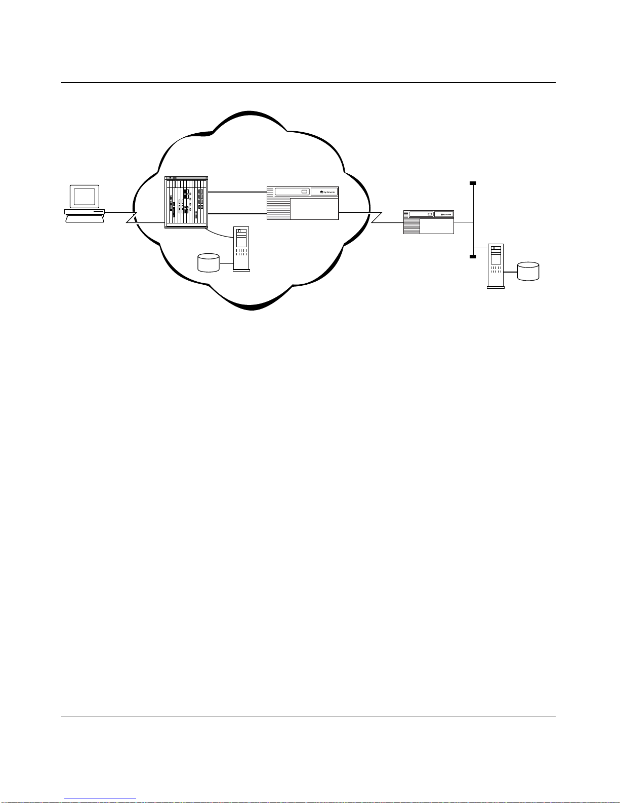
Configuring and Troubleshooting Bay Dial VPN Services
Remote
node
PPP
connection
Network
access server
(NAS)
Tunnel
domain
data
Service
provider network
T unnel
Tunnel
management server
/Service provider
RADIUS server
Gateway
Figure 6-1. Simplified Dial VPN Network
The RADIUS server on the service provider network includes a TMS database,
indexed by the domain name-DNIS pair. The fields in the database are the same as
those described for TMS in the previous chapter.
RADIUS
Client
Frame Rela y
connection
router
CPE
Customer
"Home"
network
User
data
Customer
RADIUS
server
DVS0011A
The RADIUS server parses the domain and DNIS identifier from the Username
field in the access request message and matches it against these fields in the
RADIUS TMS database.
The RADIUS server also maintains an active count of the number of sessions or
links to a particular user from a particular client. If this count exceeds the
specified limit, the RADIUS server rejects the authentication request. The
resource tracking starts with the authentication request. The server uses RADIUS
accounting information to confirm and decrement the count.
The NAS recognizes the returned tunnel attributes of the authentication request
and passes the information to its internal TMS client. The TMS client retriev es the
tunnel information it needs from the RADIUS attributes it receives in the access
acceptance message.
6-2 BayStream Multiservice Software Version 7.2 115623B Rev. 00

Configuring TMS Using Local RADIUS
The NAS uses RADIUS accounting messages to determine when the TMS tunnel
to the local RADIUS server starts and stops. The NAS logs these occurrences and
uses the information to confirm and decrement tunnel usage counts.
The NAS security parameter settings that control RADIUS also control RADIUS
support for tunneling.
Tunnel Negotiation Message Sequence
Figure 6-2 shows the flow of messages between the remote node and the
customer’s home network when the RADIUS server on the service provider’s
network maintains the TMS database.
In this dialogue, the Access-Request message from the N AS is the standard access
request for an incoming call. The provider RADIUS (TMS) server detects whether
this is a tunnel candidate by parsing the Username and Called-Number attributes.
If it does not find a valid domain or user name in the database, the TMS server to
return an Access-Reject message to the NAS.
Note: The user session’s authorization information flows from the remote
customer RADIUS return message. The local tunnel client does not have the
validated user identification until after the tunnel is formed.
115623B Rev. 00 BayStream Multiservice Software Version 7.2 6-3
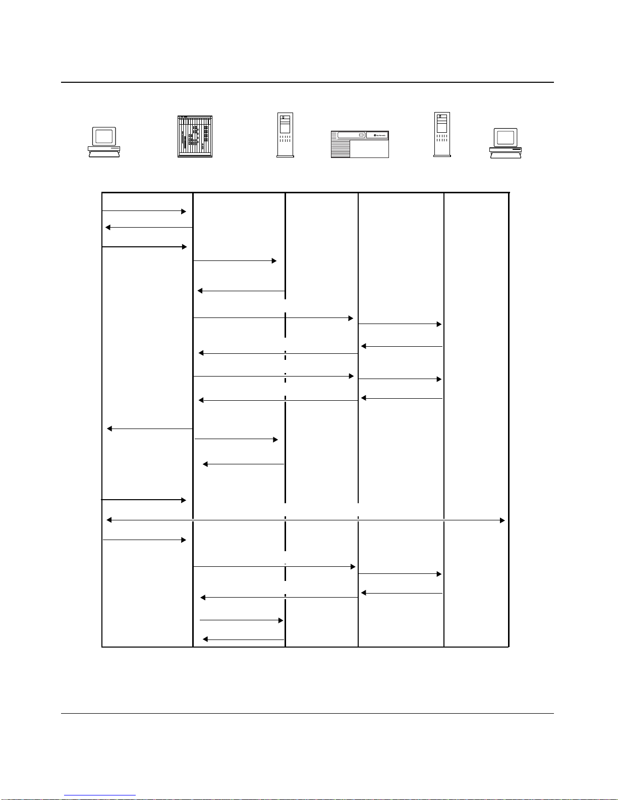
Configuring and Troubleshooting Bay Dial VPN Services
Remote
System
LCP negotiate
CHAP initiation
CHAP complete
Session start
Annex
NAS
Access request
Access response
w/Tunnel info
Acct-req (start)
Provider
RADIUS
Server
MIP auth req
MIP auth resp w/info
MIP registration req
MIP registration resp
BNX
Gateway
Auth resp w/info
Customer
Access req
Acct-req (start)
Acct-resp
RADIUS
Server
Customer
System
Acct-resp
NCP negotiation
Open Communication
Disconnect
MIP terminate msg
MIP terminate response
Acct-req (stop)
Acct-resp
Acct-req (stop)
Acct-resp
DVS0015A
Figure 6-2. Message Exchanges Supporting RADIUS TMS Operations
6-4 BayStream Multiservice Software Version 7.2 115623B Rev. 00

Handling Access Messages
When it receives an incoming call, the NAS issues a standard access-request
message to the RADIUS server . The serv er determines that this is a tunnel user by
processing the Username and Called-Number attributes. If no match for the
domain or user name in the TMS database, the server returns an access-reject
message to the NAS.
If the server finds a match in its TMS database, it returns an access-accept
message. This message contains the following attributes for the RADIUS
message:
• User name -- the original contents of the user field
• Tunnel-type -- DVS or L2TP (required); for Dial VPN, this must be DVS.
• Tunnel-media-type -- IP
• Tunnel-server-endpoint --the server address and outbound line identifier
Configuring TMS Using Local RADIUS
• Authentication-server -- the remote authentication server(s) for this user
• Accounting-server -- the remote accounting server(s) for this user
Using RADIUS Accounting
The NAS logs the tunnel-bound link sessions to the local provider’s RADIUS
server. This information does reflect the usage of the NAS ports, but it is different
from the customer (that is, the user’s home network) information, in that it may
not reflect link aggregation, and it is not based on remote user information.
The gateway generates its o wn accounting information, based on the traffic seen at
the gateway and reports this data to the customer’s RADIUS server.
The server that authenticates the tunnel also tracks resource usage through the
accounting messages it receives. The RADIUS client also preserves the Class
attribute and sends it in accounting start and stop messages to identify allocated
sessions. The user session’s authorization information flows from the customer
RADIUS server return message. The local tunnel client does not have the
validated user indentification until after the tunnel is formed.
115623B Rev. 00 BayStream Multiservice Software Version 7.2 6-5

Configuring and Troubleshooting Bay Dial VPN Services
Service Provider Accounting Messages
In general, the NAS logs sessions based on user connections just as it does for
normal session logging, but with the addition of tunnel information. Tunnel setup
exchanges that carry their own authentication information (administrati ve account
names and passwords) and/or that are not bound to dial-in ports generate separate
accounting messages. To distinguish these log messages from chargeable user
sessions, these messages carry Service-Type of Tunnel and
Accounting-Status-Type of Tunnel start and stop designators.
able 6-1 summarizes the messages that the NAS sends to the provider’s RADIUS
T
server .
Table 6-1. Service Provider Accounting Messages
Message Type/Field Name Contents
User Start Message
Acct-Status-Type Start
NAS-IP-Address, Port,
Port-Type
Username The original contents of the user field
Calling-Station_ID
Called-Station-ID
Service-Type As user authorized
Tunnel-Type DVS or L2TP
Tunnel-Media-Type IP
Acct-Client-Endpoint A string containing the IP address of the accounting client
Tunnel-Server-Endpoint A string containing the IP address of the tunnel server,
Acct-Tunnel-Connection-ID A unique identifier generated on each end of the session
Connection origination of call
Either or both, if applicable
(for Dial VPN, only DVS is valid)
system, and possibly other system-specific identifiers
the circuit type, and an optional identifier.
to identify this particular user tunnel session. Typically,
this is a numeric string encoding a tunnel identifier and/or
sequence number.
(continued)
6-6 BayStream Multiservice Software Version 7.2 115623B Rev. 00

Configuring TMS Using Local RADIUS
Table 6-1. Service Provider Accounting Messages
Message Type/Field Name Contents
User Stop Message
Acct-Status-Type Stop
NAS-IP-Address, Port,
Port-Type
Username The original contents of the user field
Calling-Station_ID
Called-Station-ID
Service-Type As user authorized
Tunnel-Type DVS or L2TP
Tunnel-Media-Type IP
Acct-Client-Endpoint A string containing the IP address of the accounting client
Tunnel-Server-Endpoint A string containing the IP address of the tunnel server,
Acct-Tunnel-Connection-ID A unique identifier generated on each end of the session
Connection origination of call
Either or both, if applicable
(for Dial VPN, only DVS is valid)
system, and possibly other system-specific identifiers
the circuit type, and an optional identifier.
to identify this particular user tunnel session. Typically,
this is a numeric string encoding a tunnel identifier and/or
sequence number.
(continued)
Statistics Connect time, bytes, messages in, messages out
Gateway Accounting Messages
The gateway sends messages to the customer RADIUS server accounting for the
inbound usage. These messages are equivalent to the user’s authorized service, as
if the user had dialed in locally, with the addition of tunnel accounting
information. T
customer’s RADIUS server.
115623B Rev. 00 BayStream Multiservice Software Version 7.2 6-7
able 6-2 summarizes the messages that the gateway sends to the

Configuring and Troubleshooting Bay Dial VPN Services
Table 6-2. Gateway Accounting Messages
Field Name Contents
NAS-IP-Address Tunnel Server IP address.
Port Local tunnel port identifier.
Port-Type Virtual.
Username The original contents of the user field.
Calling-Station_ID
Called-Station-ID
Service-Type As user authorized.
Tunnel-Type DVS or L2TP
Tunnel-Media-Type IP.
Acct-Client-Endpoint Provider NAS IP address
Tunnel-Server-Endpoint A string containing the IP address of the tunnel server,
Acct-Tunnel-Connection-ID A unique identifier generated on each end of the session
Either or both, if applicable.
(for Bay Dial VPN, only DVS is valid).
A string containing the IP address of the accounting client
system, and possibly other system-specific identifiers
the circuit type, and an optional identifier.
to identify this particular user tunnel session. Typically,
this is a numeric string encoding a tunnel identifier and/or
sequence number.
RADIUS Attributes That Support Tunneling
The attributes that support TMS come from two groups: those currently in use for
simple Layer 2 tunneling, and the additional ones needed to support the TMS data
for the remote gateway. T
able 6-3 summarizes the general tunneling attributes.
6-8 BayStream Multiservice Software Version 7.2 115623B Rev. 00

Configuring TMS Using Local RADIUS
Table 6-3. General Tunneling Attributes
Field Name Contents
Acct-Status-Type Stop
NAS-IP-Address, Port,
Port-Type
Username The original contents of the user field
Calling-Station_ID
Called-Station-ID
Service-Type As user authorized.
Tunnel-Type DVS or L2TP
Tunnel-Media-Type IP.
Acct-Client-Endpoint A string containing the IP address of the accounting client
Tunnel-Server-Endpoint A string containing the IP address of the tunnel server,
Acct-Tunnel-Connection-ID A unique identifier generated on each end of the session
Statistics Connect time, bytes, messages in, messages out.
Connection origination of call
Either or both, if applicable.
(for Bay Dial VPN, only DVS is valid).
system, and possibly other system-specific identifiers.
the circuit type, and an optional identifier.
to identify this particular user tunnel session. Typically,
this is a numeric string encoding a tunnel identifier and/or
sequence number.
Managing the TMS Default Database
By default, you use the tms_dbm program to create TMS database entries as a file
in /usr/annex, the “security” directory. The tunnel management commands are the
same as those listed in Chapter
Network.”
115623B Rev. 00 BayStream Multiservice Software Version 7.2 6-9
5, “Configuring TMS for an erpcd-based

Configuring and Troubleshooting Bay Dial VPN Services
TMS Parameters for
erpcd
-based and RADIUS-only Tunnels
While TMS operation is similar in both erpcd-based and RADIUS-only networks,
the TMS parameters differ. T
able 6-4 lists the corresponding TMS parameters for
erpcd-based and RADIUS-only networks. In this table, the parameter name is in
bold, and a sample value for it is in plain text.
Table 6-4. TMS Parameter Equivalents
RADIUS/BSAC
Tunnel Name
dhcpbsac.rem
Called station id
555-1212
Maximum open tunnels
<default=unlimited>
<integer>
Tunnel-Type
dvs
Tunnel-Server-Endpoint
200.11.11.11 fr:0x0070
200.11.11.11 fr:120
erpcd
domain
dhcpbsac.rem
dnis
555-1212
maxu
unlimited
<integer>
tutype
dvs
te, hwtype, hwaddr
(hwalen no longer needed)
200.11.11.11, fr, 0x0070
200.11.11.11, fr, 0x0070
Notes
ID should be unique to the tunnel
definition.
BSAC properly recognizes the hardware address in various hex lengths
or in decimal.
Annex-User-Server-Location
remote
local
Annex-Authen_Servers
146.146.146.2
Annex-Acct-Servers
146.146.146.2
Annex-Addr-Resolution-Protocol
DHCP
6-10 BayStream Multiservice Software Version 7.2 115623B Rev. 00
srvloc
remote
local
pauth, sauth
146.146.146.2
pacct, sacct
146.146.146.2
addrp
dhcp
For multiple servers, use the format
IPaddr1, IPaddr2.
For multiple servers, use the format
IPaddr1, IPaddr2.
(continued)

Configuring TMS Using Local RADIUS
Table 6-4. TMS Parameter Equivalents
RADIUS/BSAC
Annex-Addr-Resolution-Servers
146.146.146.200
Tunnel-Password
32 HEX chars
Annex-Sec-Profile-Index
1234
Annex-Tunnel-Authen-Type
kmd5-128
erpcd
paddr, saddr
146.146.146.200
takey
32 HEX chars
spi
1234
tatype
kmd5-128
(continued)
Notes
-- For multiple servers, use the
format IPaddr1, IPaddr2
-- If Annex-User-Server-Location
is local,
Annex-Addr-Resolution-Servers
should be locally available (same
network as the BSAC server).
-- This attribute is not used if the IP
Pooling feature on the authentication server is active for same
tunnel (BSAC only, and only for
non-MP calls).
Make sure dictionary is set for HEX
values on this attribute
If no spi (or spi=0), then tatype,
tamode, takey or their RADIUS
equivalents are not needed.
Annex-Tunnel-Authen-Mode
prefix-suffix
Annex-Local-username
<no value assigned>
Annex-Domain-Name
<no value assigned>
Tunnel-Medium-Type
IP
tamode
pref-suff
<no TMS equivalent> Required for all tunnels (locally and
<no TMS equivalent> Do not use. Reserved for future use.
<no TMS equivalent> Not required, but specify it properly
TMS System Log (Syslog) Messages
TMS, like the other elements of Dial VPN, writes its system and error messages to
the system log file, syslog. These messages are interspersed with other syslog
messages in chronological order of occurrence. For the complete list of syslog
messages, refer to Appendix
B, “Syslog Messages.”
remotely authenticated).
(IP) if used.
115623B Rev. 00 BayStream Multiservice Software Version 7.2 6-11


Chapter 7
Configuring the Gateway
At a UNIX workstation or an IBM-compatible PC serving as a management
console you can use Site Manager to create a local or dynamic configuration file
to configure the software for the gateway.
Note: Y ou can dynamically configure the gateway, then save the configuration
file, or you can alter or create a configuration file and boot the gateway from it.
Using Site Manager to Configure the Gateway
The following examples use an ASN platform, although the principles are the
same for other Bay Networks routers. Refer to the BayStream and Site Manager
documentation and to the documentation for your gateway platform for
information about all the available options.
1. Using Site Manager, select the module and slot that you want to
configure.
2. Add the circuit that you’re going to configure on that interface.
3. Select frame relay as the WAN protocol in the WAN Protocol window.
This enables frame relay on the interface you just selected. You can customize
frame relay later to suit your system’s requirements.
4. Select Mobile IP as the Layer 3 protocol in the Select Protocol window.
This automatically selects IP as well. By default, RIP is not selected.
5. Specify the IP address for this frame relay interface.
This is the “home agent” IP address. It corresponds to the tunnel endpoint (
parameter in the TMS database.
te)
115623B Rev. 00 BayStream Multiservice Software Version 7.2 7-1

Configuring and Troubleshooting Bay Dial VPN Services
6. Enter the subnet mask for this interface.
For example, enter 255.255.255.0 for a Class C subnet mask.
7. Now enable the Mobile IP home agent for each circuit.
The home agent resides on the gateway and serves as the tunnel endpoint for
messages between the remote node and the destination network.
a. To configure the Mobile IP home agent from the Configuration
Manager window, select Protocol > IP > Mobile IP > VPN Gateway.
The Edit Mobile IP Home Agents window opens.
b. Make sure that both parameters are set to Enable, then click on
Done.
Enabling the Stats Enable parameter is optional, but it aids in
troubleshooting. Collecting statistics may have a minimal effect on
performance.
8. Add and configure the security parameter index entries and keys.
To configure the Mobile IP security from the Configuration Manager window,
select Protocol > IP > Mobile IP > Security.
The Edit Mobile IP SPIs window opens, from which you can set the security
parameters.
a. Add or set the Security Parameter Index (SPI) value.
The SPI is a value that uniquely identifies a set of keys used to apply
security to messages that contain this value. The SPI v alue is an inte ger in
the range 256 through 65535. Setting the SPI value and the keys to 0 turns
off this security feature.
You add an SPI identifier by clicking Add in the Edit Mobile IP SPI’s
window. You can also add or modify a key by clicking Key.
b. Specify the keys associated with this SPI value.
Each SPI value has a 128-bit key associated with it. You must set at least
one bit in this key. The key is displayed in Site Manager as four 32-bit
fields (8 hex digits per field). Clicking on OK returns to the Edit Mobile
IP SPIs window. The SPI/key combination specified here must match the
SPI/key combination set in the TMS. The keys on both the gateway and
the TMS specify the most-significant bit (that is, bit 127) first.
c. Accept the default Authentication Type, MD5, and click on Done.
7-2 BayStream Multiservice Software Version 7.2 115623B Rev. 00

Configuring the Gateway
Configure the RADIUS client on the gateway.
9.
The RADIUS client resides on the gateway and communicates with the
RADIUS server on the destination network to authenticate dial-in users at
remote nodes. Dial VPN supports both the authentication and authorization
functions of RADIUS. To configure the RADIUS client from the
Configuration Manager window, select Protocols > IP > Mobile IP >
VPN RADIUS.
This displays the Dial VPN RADIUS window, from which you can add or
delete a RADIUS client entry.
a. Click on the slot that corresponds to the home agent’s interface.
The window “Edit RADIUS for Slot <slot number>” opens.
b. Make sure that the Authentication parameter is set to Enable.
c. If you want to enable dynamic IP addressing, set the Dynamic Client
Addressing parameter to Enable.
You must also ensure that the corresponding RADIUS server is
configured to support dynamic IP address assignment and has a pool of
assignable addresses.
d. Specify the IP address of the RADIUS client.
e. Accept the default values for all other parameters and click OK.
This returns you to the Dial VPN RADIUS window.
f. Click on Servers.
The Add RADIUS Server window opens.
g. Enter the IP address of the RADIUS server to which this client will
connect, then click OK.
This address must be a valid IP address of an actual RADIUS server.
Clicking on OK displays the frame relay Switch VC List, showing the list
of currently configured RADIUS servers.
h. Specify the Primary Secret parameter.
The gateway and the RADIUS server must each be configured with the
same secret.
i. Accept the default values for all the other parameters on this windo w ,
then click on Done.
115623B Rev. 00 BayStream Multiservice Software Version 7.2 7-3

Configuring and Troubleshooting Bay Dial VPN Services
A message appears asking whether you want to save your changes. When
you respond, you return to the Dial VPN RADIUS windo w. Keep clicking
on Done until you reach the Configuration Manager window. The
RADIUS client configuration is now complete.
Note: There can be only one RADIUS proxy client per slot, and the slot must
contain synchronous ports configured as frame relay . Only one home agent can
be configured per frame relay interface.
7-4 BayStream Multiservice Software Version 7.2 115623B Rev. 00

Chapter 8
Configuring IPX as the Routing Protocol
Dial VPN lets a dial-in user function as a remote Novell node gain access to the
home network using Internet Packet Exchange (IPX) as the dial-in protocol. IPX
is the network layer routing protocol used primarily for addressing, routing, and
switching information packets from one location to another on a Novell NetWare
network. This chapter describes the additional IPX configuration parameters
needed on each component of the network. Figure
addresses assigned in this example.
8-1 shows the Novell network
The Dial VPN components of the network shown in Figure
• A laptop computer equipped with a PCMCIA modem, configured to support
IPX over PPP using the IPX Control Protocol (IPXCP).
• A Remote Annex, Model 5393, residing in a System 5000 MSX chassis. The
Remote Annex acts as the network access server (NAS) and uses Primary
Rate ISDN.
• An ASN router, running BayStream code, that serves as the Dial VPN
gateway.
• An ASN router on the remote user’s home (CPE) network.
• A PC running LINUX and the BaySecure Access Control (BSAC) software
on the home network. This serves as the RADIUS server.
8-1 consist of:
115623B Rev. 00 BayStream Multiservice Software Version 7.2 8-1
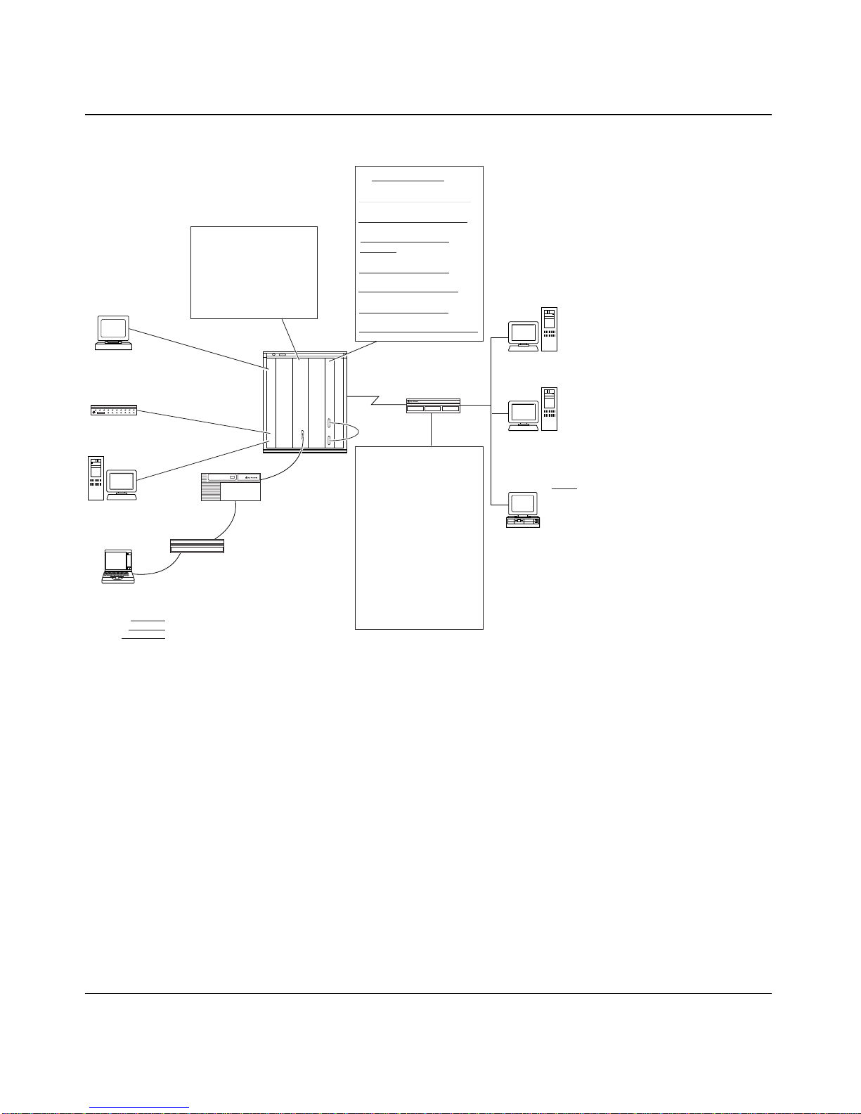
Configuring and Troubleshooting Bay Dial VPN Services
Gateway
TACO 5380 Router
E1331 132.245.54.110
Internal IP address=11.3.0.1
5393
1132.245.54.54
Console: 132.245.54.244:5008
Encryption
SPI______(256-65535)
Key____ (32 Hex digits)
S1312 FRCP=11.3.0.2
DLCI=101
S1321 GW=192.1681.1
Radius client=192.168.1.1
Radius secret=veggies
Console: 132.245.54.244.5008
VEGA
BNX Site Manager
132.245.54.20
root/vega
Bench 10
LIMA
TMS/erpod
132.245.54.9
root/lima
NATASHA
Annex/Tms Console
132.245.55.15
Bench 13
Laptop computer
10.251.0.1/255.255.0
Phone: 9.838 7929
Username:
Password:
Domain:
Adtran
Telos
5393 RAS
5393
5380
S11
E11 TCP/IP-10.250.20.1
E11 IPX-0X0000055
IPX Encapsulation=Ethernet ll
S11 TCP/IP-10.200.0.1
S11 IPX-0X00ABCDEF
IPX Encapsulation=SNAP
console=132.254.54.150.5007
1. Adjacent host=10.200.0.2
DLCI=100
2. Static Routes destination
address 192.168.1.1
next hop 10.200.0.2
mask 255.255.255.0
CPE Router
Figure 8-1. Dial VPN Network Using IPX
The remote user dials in to the NAS over an ISDN line. The NAS terminates the
PPP call and encapsulates these packets into Generic Routing Encapsulation
(GRE) packets that are passed along the backplane of the System 5000 MSX
chassis to the 5380 gateway router. This router is an ASN running BayStream
code. It is connected to the same Ethernet segment on the backplane.
LOON
Site Manager PC
Bench 7
Ethernet
10.250.20.2
E11
LINTBALL/Radius Server
Bench 7
TCP/IP address 10.250.20.3
Framed IPX Network=
00.171.205.239
Radius Secret: veggies
Mr. WIBS Novell Server
External Network Number
0X 00 00 00 55
DVS0010A
The backplane is where the “tunnel” is being created. The gateway then
terminates the GRE tunnel and sends the traffic out a frame relay DLCI that
corresponds to the appropriate home network. The home network uses another
ASN as its customer premise (CPE) router.
8-2 BayStream Multiservice Software Version 7.2 115623B Rev. 00

The CPE router is connected as a Data Terminal Equipment (DTE) device that has
an access link to the BayStream frame relay switch. The RADIUS server that
resides on the CPE network is a PC running LINUX, in this case, with the BSAC
software installed.
Setting Up Dial VPN to Use IPX
The following sections describe how to configure the components of your Dial
VPN network to support Dial VPN for IPX. This example refers to the sample
network shown in Figure
own network configuration. This example assumes that the dial-in user is using a
PC running Windows 95, but it could be running any of the following operating
systems that supports the IPXCP networking specification. This includes
Windows 95, Windows NT, and DOS or Windows running FastLink II.
Note: For detailed information on all aspects of configuring IPX on the
Remote Annex, refer to the Remote Annex Administrator’s Guide for UNIX or
the Remote Annex 6300 Supplement to the Remote Annex Administrator’ s
Guide for UNIX, as appropriate for your system. For information on
configuring IPX on the Remote Access Concentrator, refer to Managing
Remote Access Concentrators Using Command Line Interfaces.
8-1, but you can readily adapt the procedures for your
Configuring IPX as the Routing Protocol
Configuring the Dial-In Node for IPX
Assuming that the dial-in user is running a PC under Windows 95, the following
steps describe how to configure the PC as a dial-in node. In the following
descriptions, the term “Click” refers to the right mouse button, unless otherwise
specified.
1. Click on the Network Neighborhood icon.
2. On the drop-down menu, click Properties.
This displays the Network setup options.
3. On the Configuration tab, click Dial-up Adapter in the window that
displays the network components that are installed.
4. Click the Properties button.
This displays the Dial-Up Adapter Properties window.
115623B Rev. 00 BayStream Multiservice Software Version 7.2 8-3

Configuring and Troubleshooting Bay Dial VPN Services
5. If necessary, on the Driver Type tab, click the type of network driver to
use.
6. Click the Bindings tab in the Dial-Up Adapter Properties window.
This displays the protocols available for this adapter to use.
7. Click the entry for IPX/SPX-compatible Protocol > Dial-Up Adapter.
then click OK.
The dial-up node’s parameters are now properly configured.
Configuring the Network Access Server for IPX
The NAS functions as a communications server, providing shared access to the
network for dial-in IPX clients. The NAS also supports the standards-based IPX
over PPP, by means of the IPX Control Protocol (IPXCP). This lets a remote PC
user dial into a NAS as an endpoint node on an IPX network. The dial-in user can
also simultaneously run TCP/IP over the same dial-up connection.
Network access support of IPX is a software-keyed feature that can be added to a
basic unit or that is included with the Enterprise Feature Set. The first step in
configuring the NAS is to ensure that the IPX option key is turned on. To
determine which options are enabled, issue the command
superuser prompt. The IPX option should say “
keyed on”, as shown in the
stats -o from the annex
following example. (Bold type indicates user input.)
annex# stats -o
KEYED OPTIONS:
LAT: keyed off
Atalk: keyed on
tn3270: keyed on
dialout/RIP/filtering: keyed on
IPX: keyed on
Note: If IPX is keyed off, contact the Bay Networks Technical Solutions
Center.
8-4 BayStream Multiservice Software Version 7.2 115623B Rev. 00
 Loading...