

Page 1

BOOK.MKR Page i Tuesday, March 4, 1997 7:24 PM
Using the BayStack
Model 350T 10/100
Autosense Switch
Part No. 893-00992-A
March 1997
Page 2
BOOK.MKR Page ii Tuesday, March 4, 1997 7:24 PM
4401 Great America Parkway 8 Federal Street
Santa Clara, CA 95054 Billerica, MA 01821
© 1997 by Bay Networks, Inc. All rights reserved.
Trademarks
Bay Networks and Optivity are registered trademarks of Bay Networks, Inc.
Bay Networks Press, Centillion, NetICs, BayStack, and EZ LAN are trademarks of Bay Networks, Inc.
Other brand and product names are registered trademarks or trademarks of their respective holders.
Statement of Conditions
In the interest of improving internal design, operational function, and/or reliability, Bay Networks, Inc. reserves the
right to make changes to the products described in this document without notice.
Bay Networks, Inc. does not assume any liability that may occur due to the use or application of the product(s) or
circuit layout(s) described herein.
Federal Communications Commission (FCC) Statement
Note: This equipment has been tested and found to comply with the limits for a Class A digital de vice, pursuant to Part
15 of the FCC rules. These limits are designed to provide reasonable protection against harmful interference when the
equipment is operated in a commercial environment. This equipment generates, uses, and can radiate radio frequency
energy. If it is not installed and used in accordance with the instruction manual, it may cause harmful interference to
radio communications. Operation of this equipment in a residential area is likely to cause harmful interference, in
which case users will be required to take whatever measures may be necessary to correct the interference at their own
expense.
EN 55 022 Declaration of Conformance
This is to certify that the Bay Networks BayStack Model 350T 10/100 Autosense Switch is shielded against the
generation of radio interference in accordance with the application of Council Directive 89/336/EEC, Article 4a.
Conformity is declared by the application of EN 55 022 Class A (CISPR 22).
Caution: This device is a Class A product. In a domestic environment, this device can cause radio
interference, in which case, the user may be required to take appropriate measures.
ii
893-00992-A
Page 3

BOOK.MKR Page iii Tuesday, March 4, 1997 7:24 PM
Voluntary Control Council for Interference (VCCI) Statement
This equipment is in the first category (information equipment to be used in commercial and/or industrial areas) and
conforms to the standards set by the Voluntary Control Council for Interference by Data Processing Equipment and
Electronic Office Machines that are aimed at preventing radio interference in commercial and/or industrial areas.
Consequently, when this equipment is used in a residential area or in an adjacent area thereto, radio interference may
be caused to equipment such as radios and TV receivers.
893-00992-A
iii
Page 4

BOOK.MKR Page iv Tuesday, March 4, 1997 7:24 PM
iv
893-00992-A
Page 5

BOOK.MKR Page v Tuesday, March 4, 1997 7:24 PM
Preface
Audience ..........................................................................................................................xv
Organization .................................................................................................................... xv
Conventions .....................................................................................................................xvi
Special Message Formats .........................................................................................xvi
Use of Enter, Type, and Press ..................................................................................xvii
Other Conventions ...................................................................................................xvii
Ordering Bay Networks Publications ..............................................................................xvii
Bay Networks Customer Service ...................................................................................xviii
How to Get Help ............................................................................................................xviii
For More Information .......................................................................................................xix
Contents
Safety Messages
Safety Alert Message Format ..........................................................................................xxi
Safety Alert Messages Used in This Guide ...................................................................xxiii
Chapter 1
Getting Started
Overview .........................................................................................................................1-1
Hardware Description .....................................................................................................1-1
BayStack Model 350T 10/100 Autosense Switch Components ...............................1-2
Cooling Fans ............................................................................................................1-4
Features .........................................................................................................................1-4
Flash Memory Storage .............................................................................................1-6
BootP Automatic IP Configuration Capability ...........................................................1-6
SNMP MIBs Support ................................................................................................1-6
Configuration and Switch Management ...................................................................1-7
Network Configuration ....................................................................................................1-7
Connecting Power Workgroups ................................................................................1-8
Acting as a Desktop/Segment Switch ......................................................................1-9
893-00992-A
v
Page 6

BOOK.MKR Page vi Tuesday, March 4, 1997 7:24 PM
Creating Virtual LAN Workgroups ..........................................................................1-10
Quick Start ....................................................................................................................1-11
Quick Start to Installing the BayStack 350T Switch ...............................................1-12
Quick Start to Managing the BayStack 350T Switch ..............................................1-13
Managing through the Service Port Interface ..................................................1-13
Managing with SNMP Management Applications ............................................1-14
Chapter 2
Installation
Overview .........................................................................................................................2-1
Required Tools and Materials .........................................................................................2-1
Package Contents ..........................................................................................................2-2
Site Preparation ..............................................................................................................2-3
Hardware ..................................................................................................................2-3
Software ...................................................................................................................2-4
Environment .............................................................................................................2-4
Installing the BayStack 350T Switch ...............................................................................2-5
Surface Mounting .....................................................................................................2-5
Installing Mounting Brackets ..............................................................................2-6
Tabletop or Shelf Installation ..............................................................................2-7
Wall Mounting ..........................................................................................................2-8
Before Mounting the BayStack 350T Switch to a Wall .......................................2-8
Wall Mounting the Switch ..................................................................................2-9
Rack Mounting .......................................................................................................2-10
Connecting Port Cables ................................................................................................2-11
Connecting Power ........................................................................................................2-12
Verifying the Installation ................................................................................................2-13
vi
893-00992-A
Page 7

BOOK.MKR Page vii Tuesday, March 4, 1997 7:24 PM
Chapter 3
Using the Console Interface
Overview .........................................................................................................................3-1
CI Description .................................................................................................................3-1
Service Port Cabling .......................................................................................................3-2
Console Terminal Requirements ..............................................................................3-2
Modem Requirements ..............................................................................................3-2
Connecting to the BayStack 350T Switch Service Port ...........................................3-3
Accessing the CI Menus .................................................................................................3-3
Using the CI Menus ........................................................................................................3-4
Navigating the CI Menus ..........................................................................................3-4
Screen Fields and Descriptions ...............................................................................3-5
Main Menu ......................................................................................................................3-5
IP Configuration ..............................................................................................................3-8
Choosing a BootP Request Mode ..........................................................................3-10
BootP When Needed .......................................................................................3-10
BootP Always ...................................................................................................3-11
BootP Disabled ................................................................................................3-11
BootP or Last Address .....................................................................................3-12
SNMP Configuration .....................................................................................................3-13
System Characteristics .................................................................................................3-15
Switch Configuration .....................................................................................................3-17
MAC Address Table ................................................................................................3-19
VLAN Configuration ...............................................................................................3-20
Example VLAN Configuration ..........................................................................3-22
Port Configuration ..................................................................................................3-26
Port Statistics .........................................................................................................3-28
Clear Port Statistics ................................................................................................3-31
Service Port Configuration ............................................................................................3-32
Spanning Tree Configuration Menu ..............................................................................3-34
Spanning Tree Port Configuration ..........................................................................3-36
Display Spanning Tree Switch Settings ..................................................................3-38
TELNET Configuration .................................................................................................3-41
Software Download ......................................................................................................3-44
LED Indications During the Download Process .....................................................3-45
893-00992-A
vii
Page 8

BOOK.MKR Page viii Tuesday, March 4, 1997 7:24 PM
Display Event Log .........................................................................................................3-47
Excessive Bad Entries ...........................................................................................3-48
Write Threshold ......................................................................................................3-48
Reset ............................................................................................................................3-49
Reset to Default Settings ..............................................................................................3-50
Logout ........................................................................................................................... 3-51
Chapter 4
Troubleshooting
Overview .........................................................................................................................4-1
LED Description ..............................................................................................................4-2
Diagnosing and Correcting the Problem .........................................................................4-3
Normal Power-up Sequence ....................................................................................4-3
Port Connection Problems ..............................................................................................4-4
Port Interface ............................................................................................................4-4
Autonegotiation Modes ............................................................................................4-4
Appendix A
Technical Specifications
Environmental ................................................................................................................ A-1
Electrical ........................................................................................................................ A-1
Physical Size ................................................................................................................. A-1
Performance Specifications ........................................................................................... A-2
Network Protocol and Standards Compatibility ............................................................. A-2
Data Rate ...................................................................................................................... A-2
Interface Options ........................................................................................................... A-2
Safety Agency Certification ........................................................................................... A-2
Electromagnetic Emissions ........................................................................................... A-3
Electromagnetic Susceptibility .......................................................................................A-3
Declaration of Conformity .............................................................................................. A-4
viii
893-00992-A
Page 9

BOOK.MKR Page ix Tuesday, March 4, 1997 7:24 PM
Appendix B
Connectors and Pin Assignments
RJ-45 (10BASE-T/100BASE-TX Port) Connector ......................................................... B-1
MDI and MDI-X Devices ................................................................................................ B-2
MDI-X to MDI Connections ..................................................................................... B-3
MDI-X to MDI-X Connections ..................................................................................B-4
DB-9 (RS-232-D) Service Port Connector .....................................................................B-5
Appendix C
Switch Default Settings
Appendix D
Sample BootP Configuration File
Index
893-00992-A
ix
Page 10

BOOK.MKR Page x Tuesday, March 4, 1997 7:24 PM
x
893-00992-A
Page 11

BOOK.MKR Page xi Tuesday, March 4, 1997 7:24 PM
Figure 1-1. BayStack Model 350T 10/100 Autosense Switch ....................................1-1
Figure 1-2. BayStack 350T switch front and back panel ............................................1-2
Figure 1-3. BayStack 350T switches for power workgroups .......................................1-8
Figure 1-4. BayStack 350T switch as a desktop/segment switch ...............................1-9
Figure 1-5. Virtual LANs/workgroups .......................................................................1-10
Figure 1-6. Installation Flowchart .............................................................................1-12
Figure 2-1. Package contents of the BayStack 350T switch ......................................2-2
Figure 2-2. Attaching mounting brackets for a surface mount ....................................2-6
Figure 2-3. Attaching rubber footpads ........................................................................2-7
Figure 2-4. Attaching a BayStack 350T switch to a wall .............................................2-9
Figure 2-5. Attaching mounting brackets for a rack mount .......................................2-10
Figure 2-6. Installing the BayStack 350T switch in a 19-inch rack ...........................2-11
Figure 2-7. Connecting a port cable to the BayStack 350T switch ...........................2-12
Figure 2-8. Observing LEDs to verify correct operation ...........................................2-13
Figure 3-1. Map of console interface Main Menu screens .........................................3-5
Figure 3-2. CI Main Menu ...........................................................................................3-6
Figure 3-3. IP Configuration screen ...........................................................................3-8
Figure 3-4. SNMP Configuration screen ..................................................................3-13
Figure 3-5. System Characteristics screen ..............................................................3-15
Figure 3-6. Switch Configuration Menu ....................................................................3-17
Figure 3-7. MAC Address Table screen ....................................................................3-19
Figure 3-8. VLAN Configuration screen ...................................................................3-20
Figure 3-9. VLANs spanning multiple switches ........................................................3-22
Figure 3-10. VLAN Configuration screen for S1 .........................................................3-23
Figure 3-11. LAN Configuration screen for S2 ...........................................................3-24
Figure 3-12. VLAN Configuration screen for S3 .........................................................3-25
Figure 3-13. Port Configuration screen ......................................................................3-26
Figure 3-14. Port Statistics screen .............................................................................3-28
Figure 3-15. Clear Port Statistics screen ....................................................................3-31
Figures
893-00992-A
xi
Page 12

BOOK.MKR Page xii Tuesday, March 4, 1997 7:24 PM
Figure 3-16. Service Port Configuration screen .........................................................3-32
Figure 3-17. Spanning Tree Configuration Menu ........................................................3-34
Figure 3-18. Spanning Tree Port Configuration screen ..............................................3-36
Figure 3-19. Spanning Tree Switch settings screen ...................................................3-38
Figure 3-20. TELNET Configuration screen ...............................................................3-41
Figure 3-21. Software Download screen ....................................................................3-44
Figure 3-22. Event Log screen ...................................................................................3-47
Figure 3-23. Event Log entry with excessive errors example .....................................3-48
Figure 3-24. Event Log entry exceeding write threshold example .............................3-48
Figure 3-25. Reset command self-test result screen example ...................................3-49
Figure 3-26. Example of a Reset to Default command self-test result screen ...........3-50
Figure 3-27. Password prompt screen .......................................................................3-51
Figure 4-1. BayStack 350T LED Locations ................................................................4-2
Figure B-1. RJ-45 (8-pin modular) port connector ..................................................... B-1
Figure B-2. MDI-X to MDI cable connections ............................................................ B-3
Figure B-3. MDI-X to MDI-X cable connections .........................................................B-4
Figure B-4. DB-9 service port connector ................................................................... B-5
xii
893-00992-A
Page 13

BOOK.MKR Page xiii Tuesday, March 4, 1997 7:24 PM
Table 1-1. Front/back panel components ..................................................................1-3
Table 2-1. Power-up sequence of the BayStack 350T switch .................................2-13
Table 3-1. CI Main Menu commands ........................................................................3-6
Table 3-2. IP Configuration screen fields ..................................................................3-9
Table 3-3. SNMP Configuration screen fields .........................................................3-14
Table 3-4. System Characteristics screen fields .....................................................3-16
Table 3-5. Switch Configuration Menu commands .................................................3-18
Table 3-6. MAC Address Table fields ......................................................................3-19
Table 3-7. Port Configuration screen fields .............................................................3-27
Table 3-8. Port Statistics screen fields ....................................................................3-29
Table 3-9. Clear Port Statistics field ........................................................................3-32
Table 3-10. Service Port Configuration screen fields ................................................3-33
Table 3-11. Spanning Tree Configuration Menu commands .....................................3-35
Table 3-12. Spanning Tree Port Configuration screen fields .....................................3-37
Table 3-13. Spanning Tree Switch Settings screen parameters ...............................3-39
Table 3-14. TELNET Configuration screen fields ......................................................3-42
Table 3-15. Software Download screen fields ...........................................................3-45
Table 3-16. LED Indications during download process .............................................3-46
Table 4-1. BayStack 350T LED descriptions ............................................................4-2
Table 4-2. Corrective action table .............................................................................4-3
Table B-1. RJ-45 port connector pin assignments ................................................... B-2
Table B-2. Service port connector pin assignments ................................................. B-5
Table C-1. Factory default settings for the BayStack 350T switch ............................ C-1
Tables
893-00992-A
xiii
Page 14

BOOK.MKR Page xiv Tuesday, March 4, 1997 7:24 PM
xiv
893-00992-A
Page 15

BOOK.MKR Page xv Tuesday, March 4, 1997 7:24 PM
Welcome to the BayStack Model 350T 10/100 Autosense Switch, part of the Bay
Networks® BayStack™ line of communications products. This using guide
describes the features, uses, and installation procedures for the BayStack Model
350T 10/100 Autosense Switch (also referred to in this guide as the BayStack
350T switch or the switch).
Preface
Audience
This using guide is intended for network installers and administrators who are
responsible for installing, configuring, or maintaining Ethernet and Fast Ethernet
networks.
Organization
This guide has four chapters, three appendixes, and an index:
• Chapter 1—Provides a functional overview of the BayStack 350T switch.
• Chapter 2—Explains how to install and verify the operation of the BayStack
• Chapter 3—Explains how to connect to the BayStack 350T switch service
This chapter also includes a “Quick Start” section for quick access to the
switch management features.
350T switch. The chapter includes instructions for installing the switch on a
tabletop or shelf, on a wall, or into a 19-inch equipment rack.
port and how to use the console interface (CI) menus to configure and manage
the switch.
• Chapter 4—Describes how to isolate and diagnose problems with the
BayStack 350T switch as indicated by the switch LEDs.
893-00992-A
xv
Page 16
BOOK.MKR Page xvi Tuesday, March 4, 1997 7:24 PM
Using the BayStack Model 350T 10/100 Autosense Switch
• Appendix A—Lists operational and environmental specifications that apply to
the BayStack 350T switch.
• Appendix B—Describes the BayStack 350T switch connectors (ports) and
associated pin assignments.
• Appendix C—Lists factory default settings for the BayStack 350T switch.
• Index—Provides an alphabetical listing of the topics and subtopics in this
guide, with cross references to relevant information.
Conventions
This section describes the conventions used in this guide.
Special Message Formats
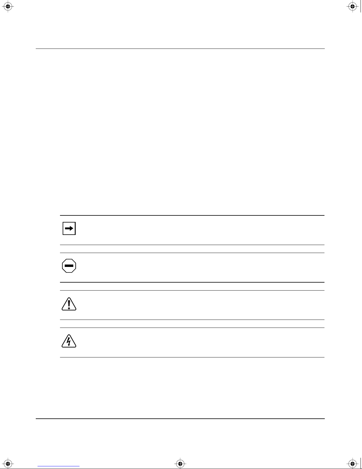
This guide uses the following formats to highlight special messages:
Note:
interest.
Caution:
equipment failure or loss of data.
Warning:
or equipment damage.
Danger:
by mishandling equipment.
This format is used to highlight information of importance or special
This format is used to highlight information that will help you prevent
This format is used to highlight material inv olving possibility of injury
This format is used to alert you that you may incur an electrical shock
xvi
893-00992-A
Page 17

BOOK.MKR Page xvii Tuesday, March 4, 1997 7:24 PM
Use of Enter, Type, and Press
This guide uses “enter,” “type,” and “press” to describe the following actions:
• When you read “enter,” type the text and press the Enter key.
• When you read “type,” type the text, but do not press the Enter key.
• When you read “press,” press only the alphanumeric or named key.
Other Conventions
This guide uses the following typographical [substitute “additional” for
“typographical” if you add the Model 500x convention] conventions:
This guide uses the following typographical conventions:
Preface
italics
Used for book titles. In command descriptions, italic type
indicates a variable that you supply.
Monospaced type Represents examples of screen text or screen field entries you
might be required to type.
[Enter] Named keys in text are shown enclosed in square brackets.
The notation [Enter] is used for the Enter key and the Return
key.
[Ctrl]+C Two or more keys that must be pressed simultaneously are
shown in text linked with a plus (+) sign.
Ordering Bay Networks Publications
To purchase additional copies of this document or other Bay Networks
publications, order by part number from Bay Networks Press™ at the following
numbers:
• Phone—U.S./Canada: 1-888-422-9773
• Phone—International: 1-510-490-4752
• Fax—U.S./Canada and International: 1-510-498-2609
You can also use these numbers to request a free Bay Networks Press catalog.
893-00992-A
xvii
Page 18

BOOK.MKR Page xviii Tuesday, March 4, 1997 7:24 PM
Using the BayStack Model 350T 10/100 Autosense Switch
Bay Networks Customer Service
You can purchase a support contract from your Bay Networks distributor or
authorized reseller, or directly from Bay Networks Services. For information
about, or to purchase a Bay Networks service contract, either call your local Bay
Networks field sales office or one of the following numbers:
Region Telephone number Fax number
United States and
Canada
Europe 33-4-92-96-69-66 33-4-92-96-69-96
Asia/Pacific 61-2-9927-8888 61-2-9927-8899
Latin America 561-988-7661 561-988-7550
How to Get Help
If you purchased a service contract for your Bay Networks product from a
distributor or authorized reseller, contact the technical support staff for that
distributor or reseller for assistance.
If you purchased a Bay Networks service program, call one of the following Bay
Networks technical response centers:
Technical Response Center Telephone number Fax number
1-800-2LANWAN; then enter Express
Routing Code (ERC) 290, when prompted,
to purchase or renew a service contract
1-508-436-8880 (direct)
1-508-670-8766
Billerica, MA 1-800-2LANWAN 508-670-8765
Santa Clara, CA 1-800-2LANWAN 408-495-1188
Valbonne, France 33-4-92-96-69-68 33-4-92-96-69-98
Sydney, Australia 61-2-9927-8800 61-2-9927-8811
Tokyo, Japan 81-3-5402-0180 81-3-5402-0173
xviii
893-00992-A
Page 19

BOOK.MKR Page xix Tuesday, March 4, 1997 7:24 PM
For More Information
For information about Bay Networks and its products, visit the Bay Networks
Worldwide Web (WWW) site at http://www.baynetworks.com. To learn more
about Bay Networks Customer Service, select Customer Service on the opening
web page.
893-00992-A
xix
Page 20

BOOK.MKR Page xx Tuesday, March 4, 1997 7:24 PM
Using the BayStack Model 350T 10/100 Autosense Switch
xx
893-00992-A
Page 21
BOOK.MKR Page xxi Tuesday, March 4, 1997 7:24 PM
Traduction des Messages de Sécurité
Traducción de los mensajes de seguridad
Safety Messages
Übersetzter Sicherheitshinweis
Messaggi relativi alla sicurezza
This section translates the safety alert messages used in this guide. Safety alert
messages notify users of unsafe actions or conditions that could lead to personal
injury or equipment damage.
Safety Alert Message Format
All safety alert messages are tagged with an international alert symbol. When you
see a safety alert in this guide, be sure to read, understand, and follow the
instructions provided before continuing with the procedure.
The safety alert messages in this guide appear in the following format:
Symbol Meaning (English, German, French, Spanish, Italian, Japanese)
Warning:
could result in personal injury.
Caution:
could result in damage to the equipment.
A warning alerts the user to some action or set of conditions that
A caution alerts the user to some action or set of conditions that
893-00992-A
xxi
Page 22
BOOK.MKR Page xxii Tuesday, March 4, 1997 7:24 PM
Using the BayStack Model 350T 10/100 Autosense Switch
Symbol Meaning (English, German, French, Spanish, Italian, Japanese)
Vorsicht:
Dieser Sicherheitshinweis macht den Benutzer auf Maßnahmen
oder Bedingungen aufmerksam, die die Verletzung von Personen zur Folge
haben können.
Achtung:
Dieser Sicherheitshinweis macht den Benutzer auf Maßnahmen
oder Bedingungen aufmerksam, die eine Beschädigung der Geräte zur Folge
haben können.
Avertissement :
La mention Avertissement attire l'attention de l'utilisateur
sur une action ou un ensemble de conditions pouvant causer des blessures
corporelles.
Attention :
La mention Attention attire l'attention de l'utilisateur sur une
action ou un ensemble de conditions pouvant endommager l'équipement visé.
Advertencia:
Un mensaje de advertencia avisa al usuario sobre una acción o
conjunto de condiciones que pueden causar daños personales.
Precaución:
Un mensaje de precaución avisa al usuario sobre alguna acción
o conjunto de condiciones que pueden dañar el equipo.
xxii
Avvertenza:
L'avvertenza indica all'utente la presenza di una o più
condizioni che possono causare lesioni fisiche.
Attenzione:
Questo messaggio indica all'utente la presenza di una o più
condizioni che possono causare danni alle apparecchiature.
893-00992-A
Page 23
BOOK.MKR Page xxiii Tuesday, March 4, 1997 7:24 PM
Safety Alert Messages Used in This Guide
The following safety alert message are used throughout this guide. Please read
and follow these instructions when you encounter them in the text.
Class A Product
Copyright page
Safety Messages
Caution:
This device is a Class A product. In a domestic environment, this
device can cause radio interference, in which case, the user may be required to
take appropriate measures.
Achtung:
Dieses Gerät ist ein Produkt der Klasse A. Bei Heiminstallationen
kann dieses Gerät Störungen des Rundfunkempfangs verursachen, wodurch
der Benutzer gegebenenfalls entsprechende Maßnahmen ergreifen muß.
Attention :
Appareil électrique de classe A pouvant causer des
radio-interférences en utilisation domestique et nécessiter, le cas échéant,
l'application de mesures correctives appropriées.
Precaución:
Este dispositivo es un producto de la Clase A. En un entorno
doméstico, este dispositivo puede producir interferencias de radio, en cuyo
caso, puede exigirse al usuario que tome las medidas de corrección
apropiadas.
Attenzione:
Questo dispositivo è un prodotto di Classe A. Se utilizzato in
ambiente domestico, può causare interferenze radio e, in tal caso, l'utente
dovrà prendere le opportune precauzioni.
893-00992-A
xxiii
Page 24
BOOK.MKR Page xxiv Tuesday, March 4, 1997 7:24 PM
Using the BayStack Model 350T 10/100 Autosense Switch
Accumulated Weight (Wall Mount)
page 2-1
Caution:
The screws and wall composition must be able to withstand the
weight of the device, plus the additional weight of the attached network cables
and power cords.
Achtung:
Schrauben und Wand müssen so beschaffen sein, daß sie dem
Gewicht des Geräts, zuzüglich des Gewichts der angeschlossenen Netzwerkund Netzstromkabel, standhalten können.
Attention :
Les vis de fixation et le mur doivent être capables de supporter le
poids du dispositif, ainsi que des câbles réseau et cordons qui y sont rattachés.
Precaución:
Los tornillos y la composición de la pared deben ser capaces de
sostener el peso del dispositivo más el peso adicional de los cables de red y
cables de alimentación conectados.
Attenzione:
Le viti e la struttura a muro devono essere in grado di sostenere
il peso del dispositivo, oltre a quello dei cavi di rete e di alimentazione
collegati.
xxiv
893-00992-A
Page 25
BOOK.MKR Page xxv Tuesday, March 4, 1997 7:24 PM
Accumulated Weight (Shelf or Table Mount)
page 2-3
Caution: When this device is installed in a stack on a shelf or tabletop, the
accumulated weight of the port cables increases with the height of the shelf or
tabletop.
Achtung: Wenn dieses Gerät in einem Stapel auf einem Tisch oder einem
Regalboden installiert wird, erhöht sich das Gesamtgewicht der
Schnittstellenkabel mit der Höhe des Regalbodens oder Tisches.
Attention : Si l'appareil est posé dans un rack ou sur une étagère, notez bien
que le poids du câblage réseau augmente avec la hauteur de l'installation.
Safety Messages
Precaución: Cuando este dispositivo se instala apilado en un estante o sobre
una mesa, el peso acumulado de los cables de los puertos aumenta según la
altura del estante o de la mesa.
Attenzione: Quando il dispositivo viene installato in stack su un ripiano o su
un tavolo, il peso dei cavi connessi alle porte aumenta in proporzione
all'altezza del ripiano o del tavolo.
893-00992-A xxv
Page 26
BOOK.MKR Page xxvi Tuesday, March 4, 1997 7:24 PM
Using the BayStack Model 350T 10/100 Autosense Switch
Hazardous Electrical Current
page 2-5
Warning: To avoid bodily injury from hazardous electrical current, do not
connect the power cord until instructed to do so.
Vorsicht: Um Verletzungsgefahr durch einen elektrischen Stromschlag
auszuschließen, schließen Sie das Netzstromkabel erst an, wenn Sie dazu
angewiesen werden.
Avertissement : Pour éliminer tout risque d'électrocution, ne jamais
brancher le cordon avant le moment indiqué dans le mode d'emploi.
Advertencia: A fin de e vitar daños personales debidos a corrientes eléctricas
peligrosas, no conecte el cable de alimentación hasta que se le indique.
Avvertenza: Per evitare lesioni fisiche dovute a scariche elettriche
pericolose, non collegare il cav o di alimentazione prima del momento indicato
nelle istruzioni.
xxvi 893-00992-A
Page 27
BOOK.MKR Page xxvii Tuesday, March 4, 1997 7:24 PM
Stacking Units in a Rack
page 2-11
Caution: When mounting this device in a rack, do not stack units directly on
top of one another in the rack. Each unit must be secured to the rack with
appropriate mounting brackets. Mounting brackets are not designed to support
multiple units.
Achtung: Wenn Sie dieses Gerät in einem Gerätegestell installieren, stellen
Sie die Geräte nicht direkt aufeinander. Jedes Gerät muß mit entsprechenden
Halterungen im Gestell befestigt werden. Die Halterungen sind nicht dafür
konzipiert, mehrere Geräte zu tragen.
Safety Messages
Attention : Si cet appareil doit être encastré dans un rack, ne jamais empiler
directement plusieurs unités les unes sur les autres. Chaque unité doit être
correctement fixée avec les membrures appropriées. Les membrures ne sont
pas conçues pour supporter le poids d'unités multiples.
Precaución: Al montar este dispositivo apilado con otros dispositivos, no
apile las unidades directamente unas sobre otras. Cada unidad se debe fijar a la
estructura mediante los soportes de montaje adecuados. Los soportes de
montaje no están diseñados para soportar varias unidades.
Attenzione: Se il dispositivo viene installato su una cremagliera, non
impilarlo su un altro dispositivo montato sulla cremagliera. Ciascuna unità
deve essere fissata alla cremagliera con le apposite staffe di montaggio. Tali
staffe non possono essere utilizzate per fissare più unità.
893-00992-A xxvii
Page 28
BOOK.MKR Page xxviii Tuesday, March 4, 1997 7:24 PM
Using the BayStack Model 350T 10/100 Autosense Switch
Turning Off Power to the Unit
page 2-12
Warning: Removal of the po wer cord is the only w ay to turn off power to this
device. The power cord must always be connected in a location that can be
accessed quickly and safely in case of an emergency.
Vorsicht: Die Stromzufuhr zu diesem Gerät kann nur durch Ziehen des
Netzstromkabels unterbrochen werden. Die Netzsteckdose, an die das
Netzstromkabel angeschlossen ist, muß sich stets an einem Ort befinden, der
bei einem Notfall schnell und einfach zugänglich ist.
Avertissement : Le débranchement du cordon d'alimentation constitue le
seul moyen de mettre cet appareil hors tension. Le cordon d'alimentation doit
donc toujours être branché dans une prise accessible pour faciliter la mise hors
tension en cas d'urgence.
Advertencia: La única forma de desconectar la alimentación de este
dispositivo es desenchufar el cable de alimentación. El cable de alimentación
siempre debe estar conectado en una ubicación que permita acceder al cable de
forma rápida y segura en caso de emergencia.
Avvertenza: Estrarre il cavo di alimentazione è l'unico sistema per spegnere
il dispositivo. Il cavo di alimentazione deve essere sempre collegato in una
posizione che permetta l'accesso facile e sicuro in caso di emergenza.
xxviii 893-00992-A
Page 29
BOOK.MKR Page xxix Tuesday, March 4, 1997 7:24 PM
Reset To Default Settings Command
page 3-7
Caution: If you choose the Reset to Default Settings command, all of your
configured settings will be replaced with factory default settings when you
press [Enter].
Achtung: Bei Auswahl des Befehls zur Rücksetzung auf die
Standardeinstellungen werden alle von Ihnen konfigurierten Einstellungen
durch die werkseitigen Standardeinstellungen ersetzt, wenn Sie die
Eingabetaste drücken.
Attention : Si vous restaurez la configuration usine, votre configuration
courante sera remplacée par la configuration usine dès que vous appuierez sur
[Entrée].
Safety Messages
Precaución: Si selecciona el comando Restaurar valores predeterminados,
todos los valores de configuración se sustituirán por las valores
predeterminados en fábrica al pulsar [Intro].
Attenzione: Nel caso in cui si selezioni la reimpostazione dei valori di
default, tutte le impostazioni configurate verranno sostituite dai default di
fabbrica premendo il tasto [Invio].
893-00992-A xxix
Page 30
BOOK.MKR Page xxx Tuesday, March 4, 1997 7:24 PM
Using the BayStack Model 350T 10/100 Autosense Switch
Choosing a Baud Rate
page 3-33
Caution: If you choose a baud rate that does not match your console terminal
baud rate, you will lose communication with the configuration interface when
you press [Enter]. If communication is lost, set your console terminal to match
the new service port setting.
Achtung: Bei Auswahl einer Baudrate, die nicht mit der Baudrate des
Konsolenterminals übereinstimmt, geht die Kommunikation mit der
Konsolenschnittstelle verloren, wenn Sie die Eingabetaste drück en. Stellen Sie
in diesem Fall das Konsolenterminal so ein, daß es mit der neuen Einstellung
der Service-Schnittstelle übereinstimmt.
Attention : Si vous sélectionnez un débit différent de celui de v otre terminal,
vous perdrez le contact avec l'interface de votre console dès que vous
appuierez sur [Entrée]. Pour restaurer la communication, alignez le débit de
votre terminal sur le nouveau débit de votre port de service.
Precaución: Si selecciona una velocidad de transmisión que no coincide con
la velocidad de transmisión del terminal de la consola, perderá la
comunicación con el interfaz de la consola al pulsar [Intro]. Si se pierde la
comunicación, ajuste el terminal de la consola para que coincida con el nuevo
valor del puerto de servicio.
Attenzione: Nel caso in cui si scelga una velocità di trasmissione non
corrispondente a quella del terminale della console, la comunicazione con
l'interfaccia della console cadrà premendo il tasto [Invio]. Se la comunicazione
cade, impostare il terminale della console in modo tale che corrisponda alla
nuova impostazione della porta di servizio.
xxx 893-00992-A
Page 31
BOOK.MKR Page xxxi Tuesday, March 4, 1997 7:24 PM
Changing Passwords
page 3-34
Caution: If you change the system-supplied default passwords, be sure to
write the new passwords do wn and k eep them in a safe place. If you for get the
new passwords, you cannot access the console interface. In that case, contact
Bay Networks for help.
Achtung: Wenn Sie die für das System standardmäßig eingestellten
Paßwörter ändern, notieren Sie sich die neuen Paßwörter, und bewahren Sie
sie an einem sicheren Ort auf. Falls Sie die neuen Paßwörter vergessen,
können Sie nicht mehr auf die Konsolenschnittstelle zugreifen. Wenden Sie
sich in diesem Fall an Bay Networks, um Unterstützung zu erhalten.
Safety Messages
Attention : Si vous changez les mots de passe par défaut du système,
assurez-vous de bien noter vos nouveaux mots de passe et de les conserver
dans un endroit sûr. Si vous perdez vos nouveaux mots de passe, vous ne
pourrez plus accéder à votre interface. Le cas échéant, veuillez contacter Bay
Networks.
Precaución: Si modifica las contraseñas predeterminadas asignadas por el
sistema, asegúrese de anotar las nuevas contraseñas y guárdelas en un lugar
seguro. Si olvida las nuevas contraseñas, no podrá acceder al interfaz de la
consola. En ese caso, póngase en contacto con Bay Networks para obtener
ayuda al respecto.
Attenzione: In caso di modifica delle password predefinite nel sistema,
assicurarsi di annotare le nuove password e di conservarle in un luogo sicuro.
Nel caso in cui le nuove password vengano dimenticate, non sarà possibile
accedere all'interfaccia della console. In tal caso, contattare la Bay Networks
per avere assistenza.
893-00992-A xxxi
Page 32
BOOK.MKR Page xxxii Tuesday, March 4, 1997 7:24 PM
Using the BayStack Model 350T 10/100 Autosense Switch
Interrupting a Software Download
page 3-44
Caution: Do not interrupt power to the device during the software download
process. If the power is interrupted, the firmware image can become corrupted.
Achtung: Unterbrechen Sie die Stromzufuhr zum Gerät nicht, während die
Software heruntergeladen wird. Bei Unterbrechung der Stromzufuhr kann das
Firmware-Image beschädigt werden.
Attention : Ne pas couper l'alimentation de l'appareil pendant le chargement
du logiciel. En cas d'interruption, le programme résident peut être
endommagé.
Precaución: No interrumpa la alimentación del dispositivo durante el
proceso de descarga del software. Si lo hace, puede alterar la imagen de la
programación (firmware).
Attenzione: Non interrompere l'alimentazione elettrica al dispositivo durante
il processo di scaricamento del software. In caso di interruzione, l'immagine
firmware potrebbe danneggiarsi.
xxxii 893-00992-A
Page 33
BOOK.MKR Page xxxiii Tuesday, March 4, 1997 7:24 PM
Removing the Top Cover
page 4-1
Warning: To avoid bodily injury from hazardous electrical current, never
remove the top cover of the device. There are no user-serviceable components
inside.
Vorsicht: Um Verletzungsgefahr durch einen elektrischen Stromschlag
auszuschließen, nehmen Sie niemals die obere Abdeckung vom Gerät ab. Im
Geräteinnern befinden sich keine Komponenten, die vom Benutzer gewartet
werden können.
Avertissement : Pour éviter tout risque d'électrocution, ne jamais retirer le
capot de l'appareil. Cet appareil ne contient aucune pièce accessible par
l'utilisateur.
Safety Messages
Advertencia: A fin de evitar daños personales por corrientes eléctricas
peligrosas, no desmonte nunca la cubierta superior de este dispositivo. Los
componentes internos no son reparables por el usuario.
Avvertenza: Per evitare lesioni fisiche dovute a scariche pericolose di
corrente, non rimuovere mai il coperchio superiore del dispositivo. I
componenti interni non possono essere manipolati dall'utente.
893-00992-A xxxiii
Page 34

BOOK.MKR Page xxxiv Tuesday, March 4, 1997 7:24 PM
Using the BayStack Model 350T 10/100 Autosense Switch
xxxiv 893-00992-A
Page 35
BOOK.MKR Page 1 Tuesday, March 4, 1997 7:24 PM
Overview
This chapter provides a functional introduction to the BayStack Model 350T 10/
100 Autosense Switch. The introduction includes a description of the ports, port
LEDs, and connectors. This chapter also discusses network configuration and
provides a Quick Start section that allows you to quickly set up switch parameters
for managing the BayStack 350T switch with SNMP management or through the
switch service port.
Chapter 1
Getting Started
Hardware Description
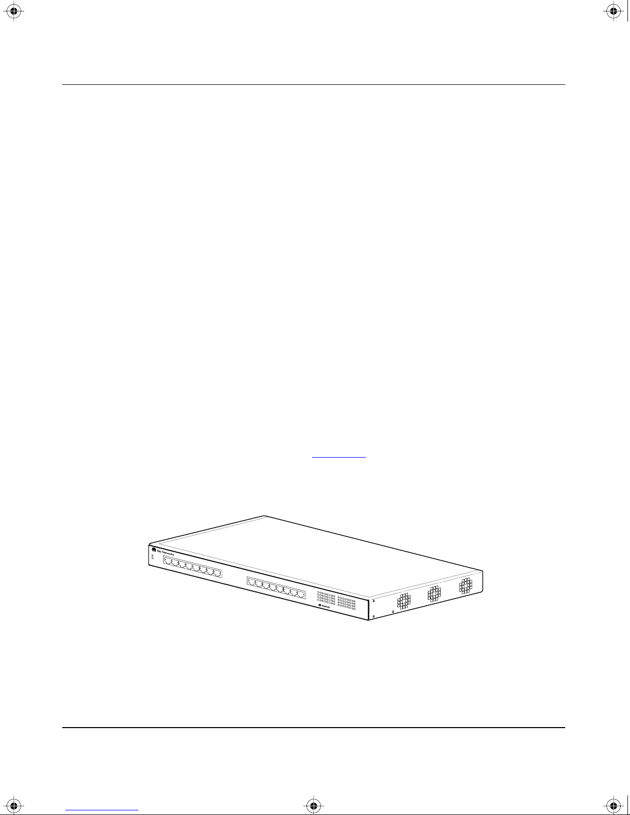
The BayStack 350T switch (see Figure 1-1) provides wire-speed, Fast Ethernet
switching that allows high-performance, low-cost connections to full-duplex and
half-duplex 10 megabit per second (Mb/s) and 100 Mb/s Ethernet LANs.
Figure 1-1. BayStack Model 350T 10/100 Autosense Switch
350T
10/100 Autosense Switch
540FA
893-00992-A 1-1
Page 36
BOOK.MKR Page 2 Tuesday, March 4, 1997 7:24 PM
Using the BayStack Model 350T 10/100 Autosense Switch
Based on advanced application-specific integrated circuit (ASIC) technology, the
BayStack 350T switch can be cost effectiv ely deployed into 10 Mb/s networks. As
performance requirements grow and 100 Mb/s LANs are deployed, each port uses
autosensing to support any mix of 10 Mb/s and 100 Mb/s Ethernet LANs.
One of the many benefits provided by the BayStack 350T switch is that network
users now have the flexibility to grow from 10 Mb/s switching to 100 Mb/s
switching in a single product.
BayStack 350T switching technology supports a rich feature set including virtual
LANs (VLANs) and remote monitoring (RMON).
BayStack Model 350T 10/100 Autosense Switch Components
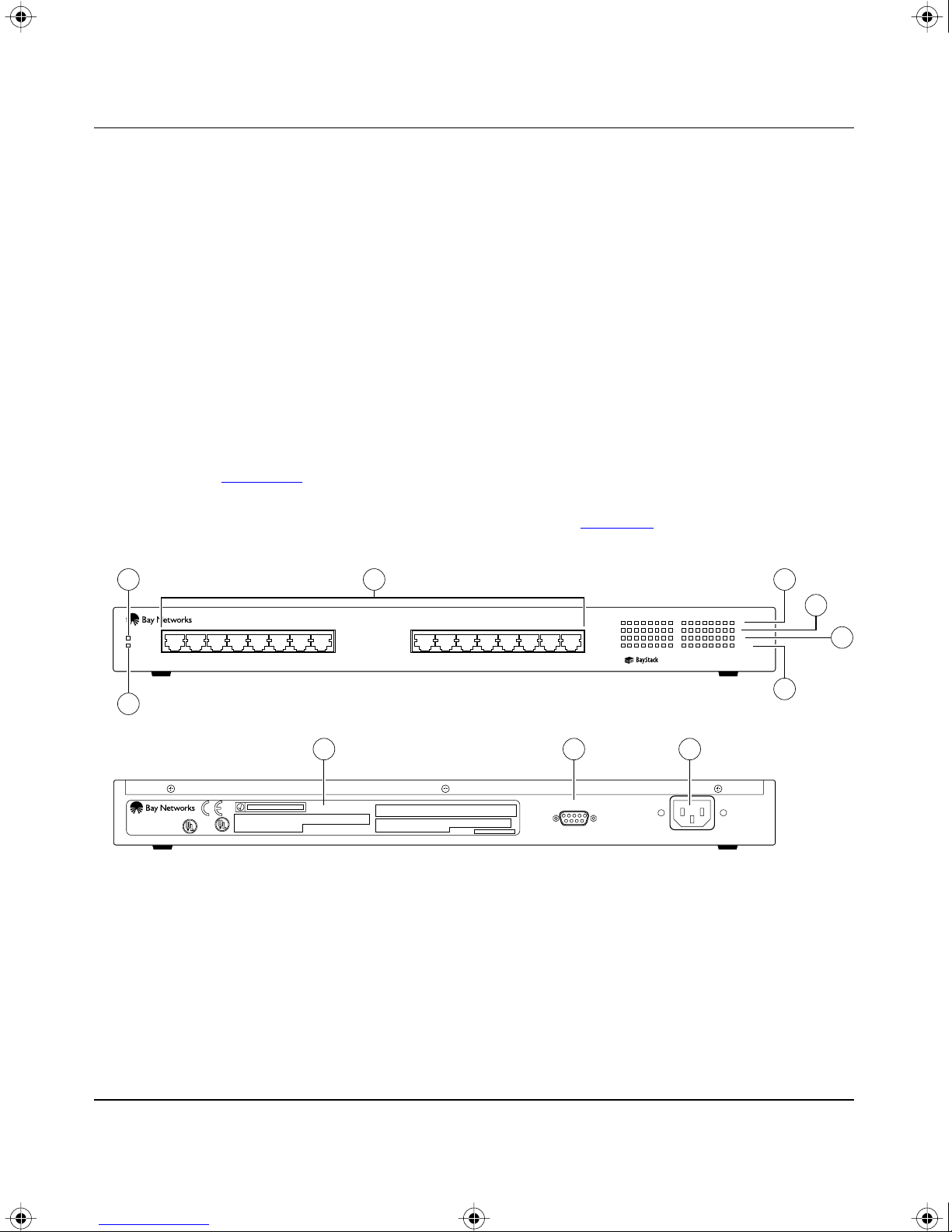
Figure 1-2 identifies the location of the BayStack 350T switch ports,
corresponding status LEDs, service port, and AC power receptacle. For a
description of each numbered component, see T
1 4
Power
Diagnostics
2
8910
BayStack 350T
M/N AL2012A01
Figure 1-2. BayStack 350T switch front and back panel
3
1312345678 10 11 129
14 15 16
able 1-1.
RS232
2345678
1 9 10 11 12 13 14 15 16
100
10
FDx
Activity
350T 10/100 Autosense Switch
100
10
F Dx
Activity
5
6
7
583EA
1-2 893-00992-A
Page 37

BOOK.MKR Page 3 Tuesday, March 4, 1997 7:24 PM
Table 1-1 describes the components of the BayStack 350T switch as numbered in
Figure
Table 1-1. Front/back panel components
Item Icon/label Description
1 Power Power LED
2 Diagnostics Diagnostics LED
3 1 through 16 10BASE-T/100BASE-TX RJ-45 (8-pin modular) port connectors:
1-2.
Green DC power is available to the switch’s internal circuitry.
Green The switch passes the self-test.
Blinking A nonfatal error occurs during the self-test.
Off The switch fails the self-test.
Require 100-ohm unshielded twisted-pair (UTP) cable. The RJ-45 connectors are
wired as MDI-X ports to connect end stations without using crossover cables.
Getting Started
4 100 100BASE-TX Port Status LEDs, Ports 1 through 16:
Green The corresponding port is set to operate at 100 Mb/s.
Green blinking The corresponding port is management disabled.
5 10 10BASE-T Port Status LEDs (yellow), Ports 1 through 16:
Yellow The corresponding port is set to operate at 10 Mb/s.
Yellow blinking The corresponding port is management disabled.
6 FDX Full-Duplex Port Status, Ports 1 through 16:
Green The corresponding port is in full-duplex mode.
Off The corresponding port is in half-duplex mode.
7 Activity Port Activity, ports 1 through 16:
Green blinking Network activity for the corresponding port. Strong network
activity can cause LEDs to appear to be continuously on.
8 Manufacturing Label—Lists the device model number, serial number, MAC
address, and voltage rating.
9 RS232 Service Port DB-9 (RS-232-D) serial port connector:
Allows attachment of a console terminal device for accessing the console interface
(CI) screens.
10 AC Power Receptacle—Accepts AC power cord (supplied).
893-00992-A 1-3
Page 38

BOOK.MKR Page 4 Tuesday, March 4, 1997 7:24 PM
Using the BayStack Model 350T 10/100 Autosense Switch
Cooling Fans
Three variable-speed cooling fans in the BayStack 350T switch provide cooling
for the internal components. Cooling air is drawn into air vents located on one
side of the switch and expelled through the fans at the opposite side. When you
install the switch, be sure to allow space at the sides of the switch for adequate
airflow.
Features
The BayStack 350T switch includes the following features:
• High-speed forwarding rate—1.6 million packets per second peak
• Learning rate—1.6 million addresses per second peak
• Spanning Tree Protocol—IEEE 802.1D standards compliant
• Store-and-forward switch—full performance forwarding at full line speed
• Simple Network Management Protocol (SNMP) agent support for the
following Management Information Bases (MIBs):
— Bridge MIB (RFC 1493)
— Ethernet MIB (RFC 1643)
— Proprietary MIBs
— RMON MIB (RFC 1757)
— MIB II (RFC 1213)
• Service port for console connection—allows users to locally or remotely
configure and manage the switch
• TELNET
— Support for up to four simultaneous TELNET sessions
— Optional password protection
— Login timeout
— Failed-login guard
— Inactivity timeout
— Allowed source addresses
— Event logging
1-4 893-00992-A
Page 39

BOOK.MKR Page 5 Tuesday, March 4, 1997 7:24 PM
• IEEE 802.3u-compliant autonegotiation ports, with four modes:
— 10BASE-T half-duplex
— 10BASE-T full-duplex
— 100BASE-TX half-duplex
— 100BASE-TX full-duplex
• Remote monitoring (RMON) with four groups integrated:
— Statistics
— History
— Alarms
— Events
• Port-based virtual LANs (VLANs)
Getting Started
• Front panel light emitting diodes (LEDs) for monitoring the following:
— Power status
— System status
— Per port status for the following:
• 100 Mb link
• 10 Mb link
• Half- and full-duplex transmission
• TX/RX activity
• Management enable/disable
• Upgradeable device firmware in nonvolatile flash memory using Trivial File
Transfer Protocol (TFTP)
893-00992-A 1-5
Page 40

BOOK.MKR Page 6 Tuesday, March 4, 1997 7:24 PM
Using the BayStack Model 350T 10/100 Autosense Switch
Flash Memory Storage
The BayStack 350T switch uses flash memory to store the switch software image.
Flash memory allows you to update the software image with a newer version
without changing the switch hardware. An in-band connection between the switch
and the TFTP load host is required to download the software image (refer to
Software Download” on page 3-44). For information about connecting a console
“
terminal for this procedure, refer to “
If the BayStack 350T switch detects a corrupted software image during self-test, it
automatically downloads a new software image, using the Bootstrap (BootP) and
TFTP protocols.
BootP Automatic IP Configuration Capability
Service Port Cabling” on page 3-2.
The BayStack 350T switch has a unique 48-bit hardware address, or MAC
address, that is printed on a label on the back panel. This is the MA C address you
use when you configure your network BootP server to recognize the BayStack
350T switch BootP requests. A properly configured BootP server allows the
switch to automatically learn its assigned IP address, its subnet mask, the IP
address of the default router (default gateway), and the software image file name.
Refer to Appendix
BootP configuration file.
SNMP MIBs Support
The BayStack 350T switch supports an SNMP agent with private MIB e xtensions.
Built-in SNMP agent support ensures compatibility with existing network
management tools. The BayStack 350T switch supports MIB-II (RFC 1213)
standards that provide access to detailed management statistics. With SNMP
management, you can configure SNMP traps to be generated automatically for
conditions such as an unauthorized access attempt or changes in operating status
on individual ports.
D, “Sample BootP Configuration File,” to see an example of a
1-6 893-00992-A
Page 41

BOOK.MKR Page 7 Tuesday, March 4, 1997 7:24 PM
Configuration and Switch Management
The BayStack 350T switch is shipped direct from the factory ready to operate in
any 10BASE-T or 100BASE-TX standard network. You can manage the switch
with Optivity
network management software; however, you must assign an IP network address
to the switch. You can set the BayStack 350T IP address by using the service port
or by using the BootP protocol resident in the BayStack 350T switch. For more
information about using the service port for manual configuration of the switch,
see Chapter
Network Configuration
The BayStack 350T switch can be connected to workstations and personal
computers (PCs) either directly, through a hub, or through the creation of
virtual LANs (VLANs). This section shows three network examples using the
BayStack 350T switch in the following configurations:
Getting Started
®
network management software, or with any generic SNMP-based
3, “Using the Console Interface.”
• Desktop connections for power workgroups
• Desktop connections for power workgroups and shared media hub
• Virtual LAN workgroups
893-00992-A 1-7
Page 42
BOOK.MKR Page 8 Tuesday, March 4, 1997 7:24 PM
Using the BayStack Model 350T 10/100 Autosense Switch
Connecting Power Workgroups
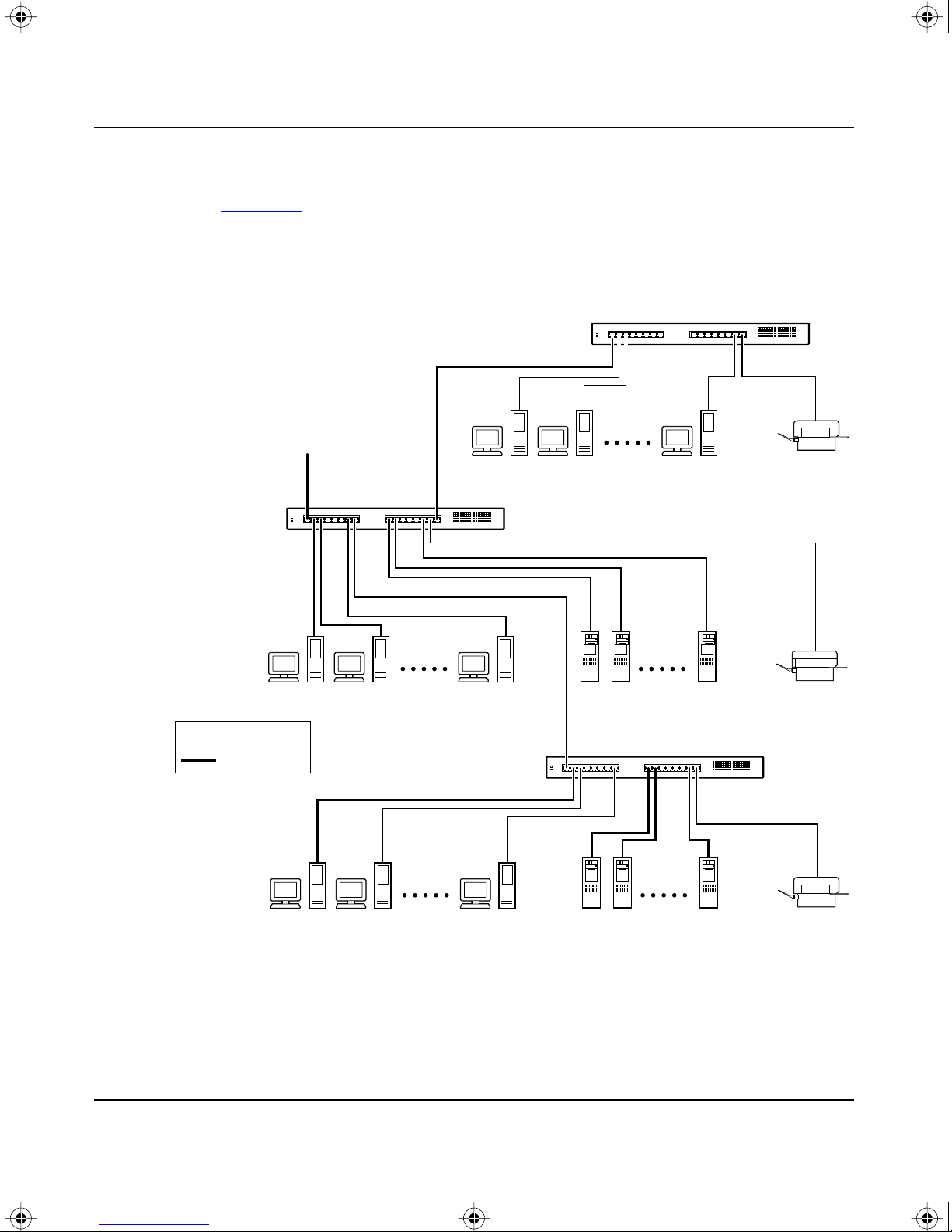
Figure 1-3 shows BayStack 350T switches connecting a mixture of dedicated
power workgroups along with standard departmental users. In this example, all
users have access to 10 Mb/s bandwidth or 100 Mb/s bandwidth on any port.
To
network
center
BayStack 350T switch
Key
BayStack 350T switch
10 Mb/s
100 Mb/s
BayStack 350T switch
Figure 1-3. BayStack 350T switches for power workgroups
620EA
1-8 893-00992-A
Page 43
BOOK.MKR Page 9 Tuesday, March 4, 1997 7:24 PM
Acting as a Desktop/Segment Switch
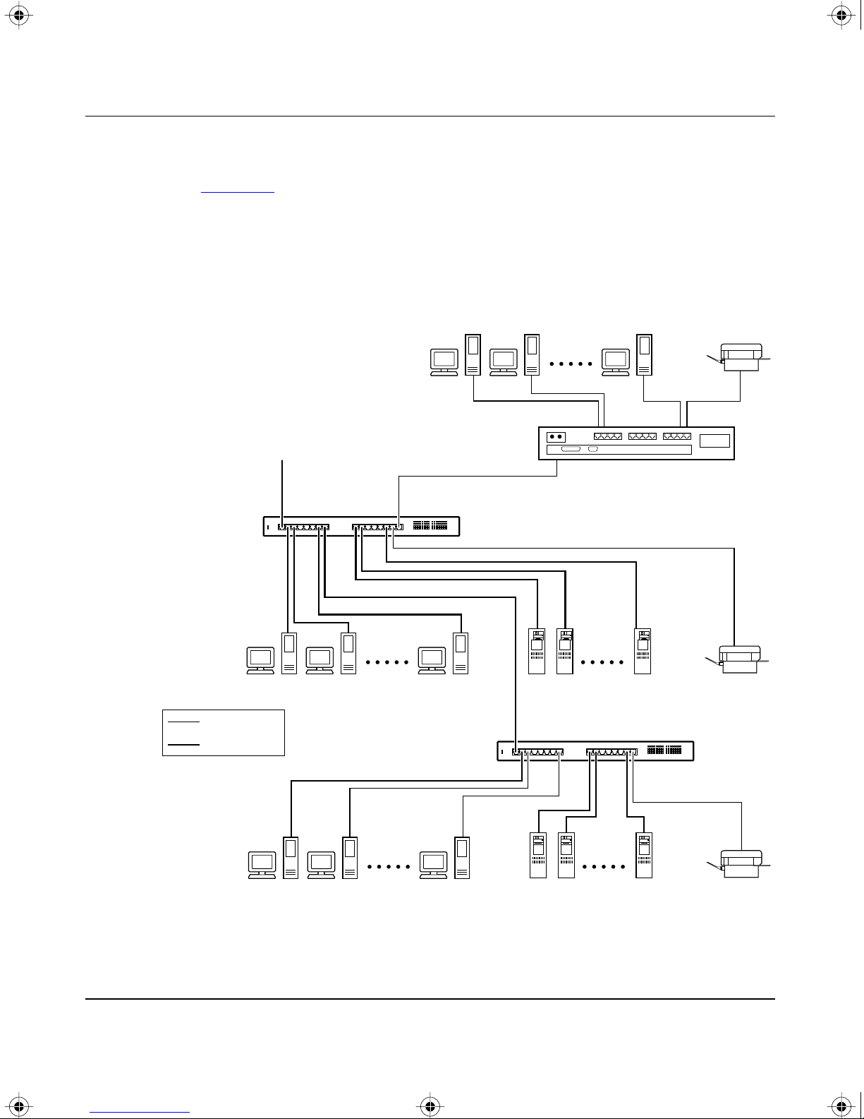
Figure 1-4 shows groups of power users connected to servers through BayStack
350T switches in a small network. Network managers who do not want to provide
each end station with the full 100 Mb/s bandwidth can designate a certain number
of users to share the full bandwidth provided by one port of the switch. For
example, one of the workgroups, connected to a 10BASE-T hub, is sharing
10 Mb/s bandwidth provided by one of the BayStack 350T switch ports.
To
network
center
Getting Started
10BASE-T hub
Key
BayStack 350T switch
10 Mb/s
100 Mb/s
BayStack 350T switch
Figure 1-4. BayStack 350T switch as a desktop/segment switch
621EA
893-00992-A 1-9
Page 44
BOOK.MKR Page 10 Tuesday, March 4, 1997 7:24 PM
Using the BayStack Model 350T 10/100 Autosense Switch
Creating Virtual LAN W orkgroups
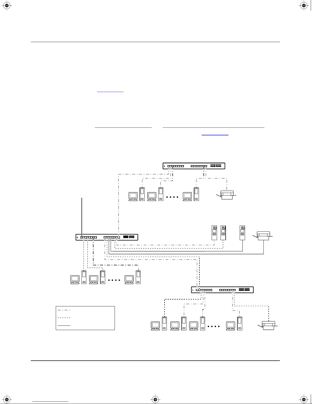
You can create and configure virtual LANs (VLANs) by segmenting networks
into logical workgroups that are independent of physical connections and
locations. The workgroups can be defined according to project or department. As
shown in Figure
but cannot communicate with other workgroups. Access to specific servers is
restricted to all except the assigned workgroup. Broadcast packets are confined to
a specific VLAN, which relieves traffic congestion.
1-5, workgroup members on VLANs share computer resources
Refer to “
VLAN Configuration” in Chapter 3, “Using the Console Interface” to
see how the individual BayStack 350T switches in Figure
this topology example.
BayStack 350T switch
S2
To
network
center
100 Mb/s
S1
BayStack 350T switch
1-5 are configured for
V2
V1 + V2
V1
Key
VLAN1 V1
VLAN2 V2
VLAN V1 + V2
Figure 1-5. Virtual LANs/workgroups
1-10 893-00992-A
BayStack 350T switch
S3
622EA
Page 45

BOOK.MKR Page 11 Tuesday, March 4, 1997 7:24 PM
Quick Start
This section provides Quick Start procedures for installing and setting up the
BayStack 350T switch. It is intended for experienced installers or system
administrators that are familiar with the BayStack 350T switch installation and
setup procedures provided in this manual.
If you are experienced in installing network devices, or if you are installing
multiple BayStack 350T switches, you can probably use the installation flowchart
provided in this section to guide you through the installation. If you need more
information about any of the steps listed in the flowchart, refer to Chapter
“Installation” for a complete explanation of the installation process.
After you have verified the installation, you can use other Quick Start procedures
in this section to set up and begin the management of the switch. Refer to
Chapter
the switch and using the console interface (CI) screens.
3, “Using the Console Interface” for detailed information about setting up
Getting Started
2,
893-00992-A 1-11
Page 46
BOOK.MKR Page 12 Tuesday, March 4, 1997 7:24 PM
Using the BayStack Model 350T 10/100 Autosense Switch
Quick Start to Installing the BayStack 350T Switch
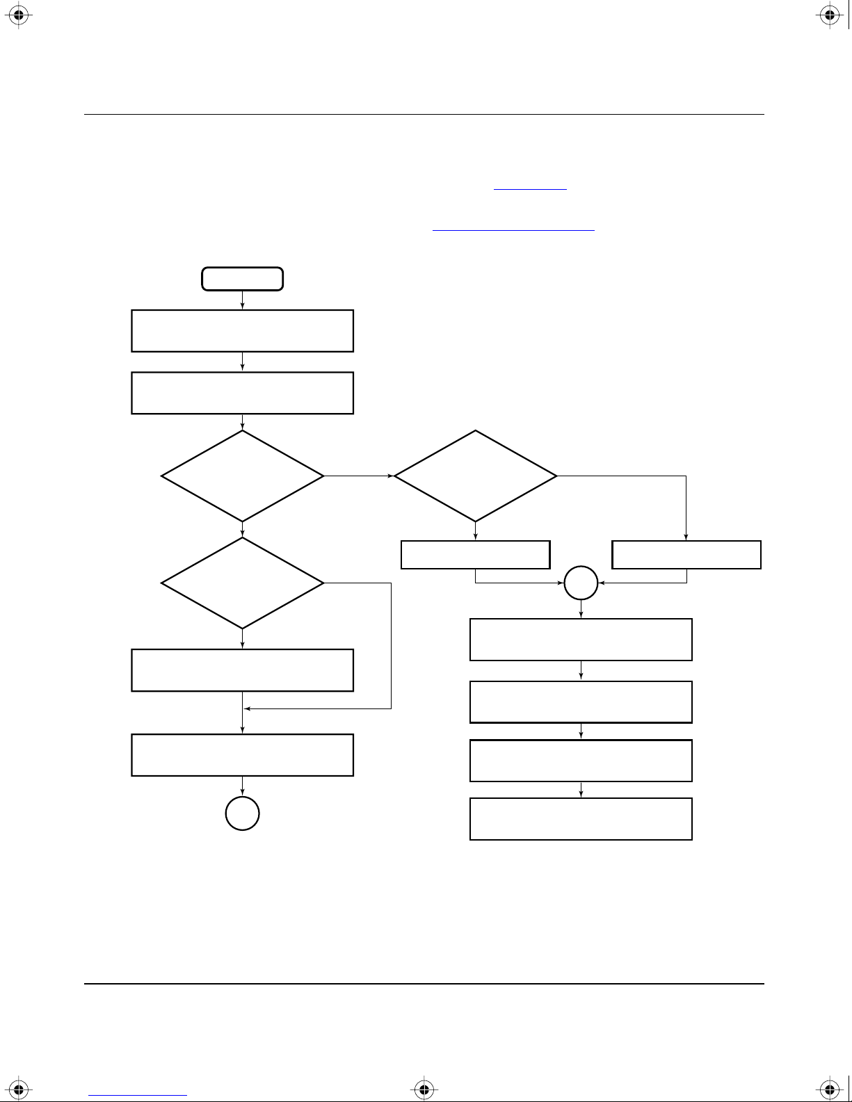
You can use the installation flowchart (see Figure 1-6) to install the BayStack
350T switch. If you need more information about any of the steps in the flowchart,
refer to the appropriate section in Chapter
Start
Check contents of
shipping box
Check site preparation
requirements
2, “Installation.”
Tabletop
or shelf mounting
switch?
Yes
Secure
switch to mounting
surface?
Yes
Install mounting brackets
Install on tabletop
or shelf
A
No
No
Wall mounting
switch?
Yes
Install onto wall Install into rack
No
A
Connect port cables
Connect power
Verify the installation
Configure the switch
for management
721EA
Figure 1-6. Installation Flowchart
1-12 893-00992-A
Page 47

BOOK.MKR Page 13 Tuesday, March 4, 1997 7:24 PM
Quick Start to Managing the BayStack 350T Switch
If you are already familiar with managing network devices, you can use the Quick
Start procedures provided in this section to set up and begin managing the
BayStack 350T switch. The procedures assume that the BayStack 350T switch
has been installed and verified (as described in Chapter
your network cables are attached to the switch.
This section describes how to manage the BayStack 350T switch using either of
two methods:
• Through the Service Port Interface, using the CI screens
• Using an SNMP Management Application
Managing through the Service Port Interface
Getting Started
2, “Installation”), and
If you are managing the BayStack 350T switch through the service port interface,
follow these steps:
1. Connect a console terminal directly to the BayStack Model 350T service
port or through a modem.
The console terminal can be a VT100 terminal or a PC running VT100
terminal-emulation software (refer to “Service Port Cabling” in Chapter
3,
“Using the Console Interface”).
2. Configure the console terminal for 9600 baud, 8 data bits, no parity, and
1 stop bit.
Be sure to place the console terminal online; do not leave it in setup mode.
3. Press [Ctrl]+C on the console terminal keyboard.
4. The console interface (CI) Main Menu appears on the screen.
For more information about the CI Main Menu, refer to“
in Chapter
3, “Using the Console Interface.”
Using the CI Menus”
893-00992-A 1-13
Page 48

BOOK.MKR Page 14 Tuesday, March 4, 1997 7:24 PM
Using the BayStack Model 350T 10/100 Autosense Switch
Managing with SNMP Management Applications
If you are using an SNMP management application to manage the BayStack 350T
switch, you must first assign an IP address to the switch so that the SNMP
management software can communicate with the switch.
To enter the BayStack 350T switch IP address, follow these steps:
1. Connect a console terminal directly to the BayStack 350T switch service
port or through a modem.
The console terminal can be a VT100 terminal or a PC running VT100
terminal-emulation software (see “
the Console Interface”).
2. Configure the console terminal for 9600 baud, 8 data bits, no parity, and
1 stop bit.
Service Port Cabling” in Chapter 3, “Using
Be sure to place the console terminal online; do not leave it in setup mode.
3. Press [Ctrl]+C on the console terminal keyboard.
4. The console interface (CI) Main Menu appears on the screen (see “Using
the CI Menus” in Chapter 3, “Using the Console Interface”).
5. Select the IP Configuration option from the Main Menu.
The IP Configuration screen is displayed.
6. In the IP Configuration screen, fill in the following fields:
— In-Band IP Address
— In-Band Subnet Mask (if required)
— Default Gateway (if required)
7. Set SNMP traps, if needed.
To set SNMP traps, refer to “SNMP Configuration” in Chapter
3, “Using the
Console Interface.”
8. Press [Ctrl]+C to return to the Main Menu.
1-14 893-00992-A
Page 49

BOOK.MKR Page 1 Tuesday, March 4, 1997 7:24 PM
Overview
This chapter explains how to install the BayStack Model 350T 10/100 Autosense
Switch. The switch can be placed freestanding onto a tabletop or shelf, mounted
on a wall, or installed into a 19-inch equipment rack.
Chapter 2
Installation
Installing the BayStack 350T switch consists of unpacking the equipment,
physically installing the switch, connecting the network cables, and then
connecting the power.
Required Tools and Materials
The following tools are required to install the BayStack 350T switch:
• For installation in a standard 19-inch equipment rack—use a Phillips (or
cross-head) screwdriver.
• For wall mounting—four screws (not supplied) are required to mount the
BayStack 350T switch onto a wall. The screw size and type depends on the
wall composition where you intend to mount the switch. Have an e xperienced
maintenance person choose the appropriate hardware according to your wall
composition.
Caution: The screws and wall composition must be able to withstand the
weight of the device, plus the additional weight of the attached network cables
and power cords.
893-00992-A 2-1
Page 50
BOOK.MKR Page 2 Tuesday, March 4, 1997 7:24 PM
Using the BayStack Model 350T 10/100 Autosense Switch
Package Contents
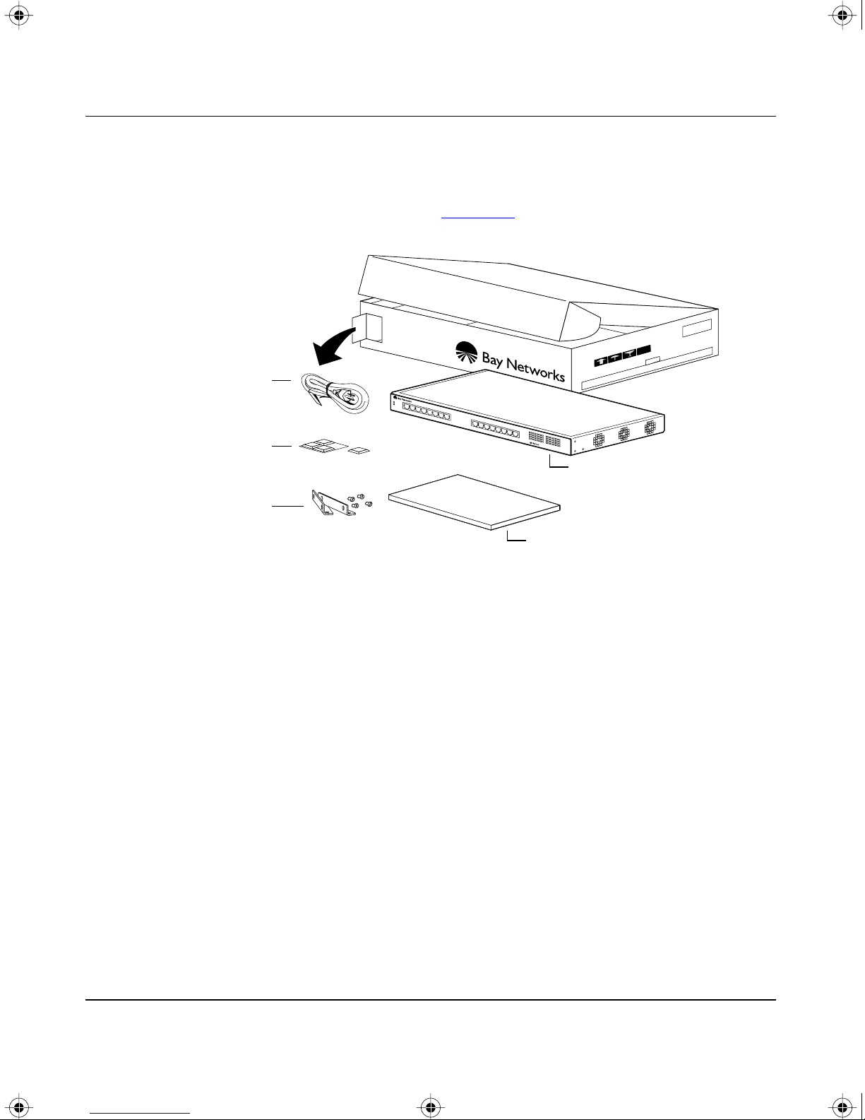
While unpacking the equipment, verify that your BayStack 350T switch shipment
includes all of the items shown in Figure
AC
power cord
2-1.
Rubber
footpads
Mounting
brackets
and screws
350T
10/100 Autosense Switch
BayStack Model 350T
10/100 Autosense Switch
Using the BayStack Model 350T
10/100 Autosense Switch manual
584FA
Figure 2-1. Package contents of the BayStack 350T switch
If any items are missing or damaged, contact the sales agent or the customer
service representative where you purchased your BayStack 350T switch.
2-2 893-00992-A
Page 51

BOOK.MKR Page 3 Tuesday, March 4, 1997 7:24 PM
Site Preparation
Before beginning the switch installation, use the following checklist to ensure that
your site is ready.
Hardware
Verify that you have the following hardware components appropriate to your
method of installation:
• Console terminal—Ensure that you have a console terminal available. The
terminal must be a VT100-compatible terminal or a PC running VT100
terminal-emulation software. (Although the BayStack 350T switch is
operational as soon as you install it, you can customize the operational
parameters to suit your needs.)
Installation
• Rack mounting—You need a single unit rack space for installing the
BayStack 350T switch into a standard 19-inch equipment rack.
• Surface mounting:
— Tabletop—The table or shelf must be level and able to support at least
10 pounds, plus the additional weight of the suspended port cables. If you
intend to stack additional BayStack 350T switches, one on top of another,
remember to include this added weight in your calculations when
selecting a suitable table or shelf.
Caution: When this device is installed in a stack on a shelf or
tabletop, the accumulated weight of the port cables increases with the
height of the shelf or tabletop.
— Wall mount screws—Mounting brackets are provided for securing the
BayStack 350T switch onto a tabletop, shelf, or wall. However, because
of the various types of wall compositions available at various sites, Bay
Networks recommends that an experienced maintenance person choose
the appropriate wall mounting hardware to safely mount your BayStack
350T switch onto your wall.
• Network cabling—Ensure that all network cables are in place and that they
have been tested and tagged before you begin the installation.
893-00992-A 2-3
Page 52

BOOK.MKR Page 4 Tuesday, March 4, 1997 7:24 PM
Using the BayStack Model 350T 10/100 Autosense Switch
Software
Verify that you have the following software components appropriate to your
method of installation:
• BootP server—The BayStack 350T switch is capable of learning its IP
address through the Bootstrap Protocol (BootP). To use this feature, ensure
that a properly configured BootP server is present in your network.
• TFTP server—You can keep your BayStack 350T switch firmware up to date
by upgrading the firmware as new versions become available. To upgrade the
firmware, you need a properly configured Trivial File Transfer Protocol
(TFTP) server in your network.
The Bay Networks network management applications EZ LAN
™
Campus
functions.
, and Optivity Enterprise™ can help you with these BootP and firmware
™
, Optivity
Environment
Be sure that the following items conform to the specifications described in
Chapter
• Temperature—Ensure that the temperature in the operating environment
A, “Technical Specifications”:
remains between 0
o
and 40o C (32o and 104o F). Do not place the BayStack
350T switch in direct sunlight or near warm air exhausts or heaters.
• Humidity—Ensure that the humidity level in the operating environment does
not exceed 85 percent and that no water condenses on or around the BayStack
350T switch.
• Ventilation—Ensure that there is adequate airflow and clearance for air
circulation around the BayStack 350T switch. Air enters the BayStack 350T
switch from one side of the unit and flows out the opposite side. Allo w at least
two inches of ventilation space on both sides of the BayStack 350T switch.
• Electrical Power—Ensure that the site’s power outlet matches the power
requirement of the BayStack 350T switch and is within 1.8 meters (6 feet) of
the installation site.
2-4 893-00992-A
Page 53
BOOK.MKR Page 5 Tuesday, March 4, 1997 7:24 PM
Installing the BayStack 350T Switch
This section explains how to install, power up, and verify the operation of the
BayStack 350T switch. Before you begin these procedures, read and follow the
instructions in “
Warning: To avoid bodily injury from hazardous electrical current, do not
connect the power cord until instructed to do so.
The BayStack 350T switch can be installed in any of the following locations:
• Surface mount
— Tabletop or shelf (secured or unsecured)
Installation
Site Preparation” on page 2-3.
— Wall mount
• Rack mount—19-inch equipment rack
Surface Mounting
The BayStack 350T switch can be surface mounted onto any appropriate surface
that can safely support the weight of the switch and attached cables, as long as
there is adequate space around the unit for ventilation and access to cable
connectors. Mounting brackets supplied with the switch allow you to secure the
BayStack 350T switch to the installation location.
Note: In most cases it is not necessary to secure the BayStack 350T switch
onto a tabletop or shelf. However, if conditions warrant securing the switch,
such as when installing the switch at locations that are subject to heavy traffic
or at overhead locations, you can secure the BayStack 350T switch with two
mounting brackets (supplied).
893-00992-A 2-5
Page 54
BOOK.MKR Page 6 Tuesday, March 4, 1997 7:24 PM
Using the BayStack Model 350T 10/100 Autosense Switch
Installing Mounting Brackets
Figure
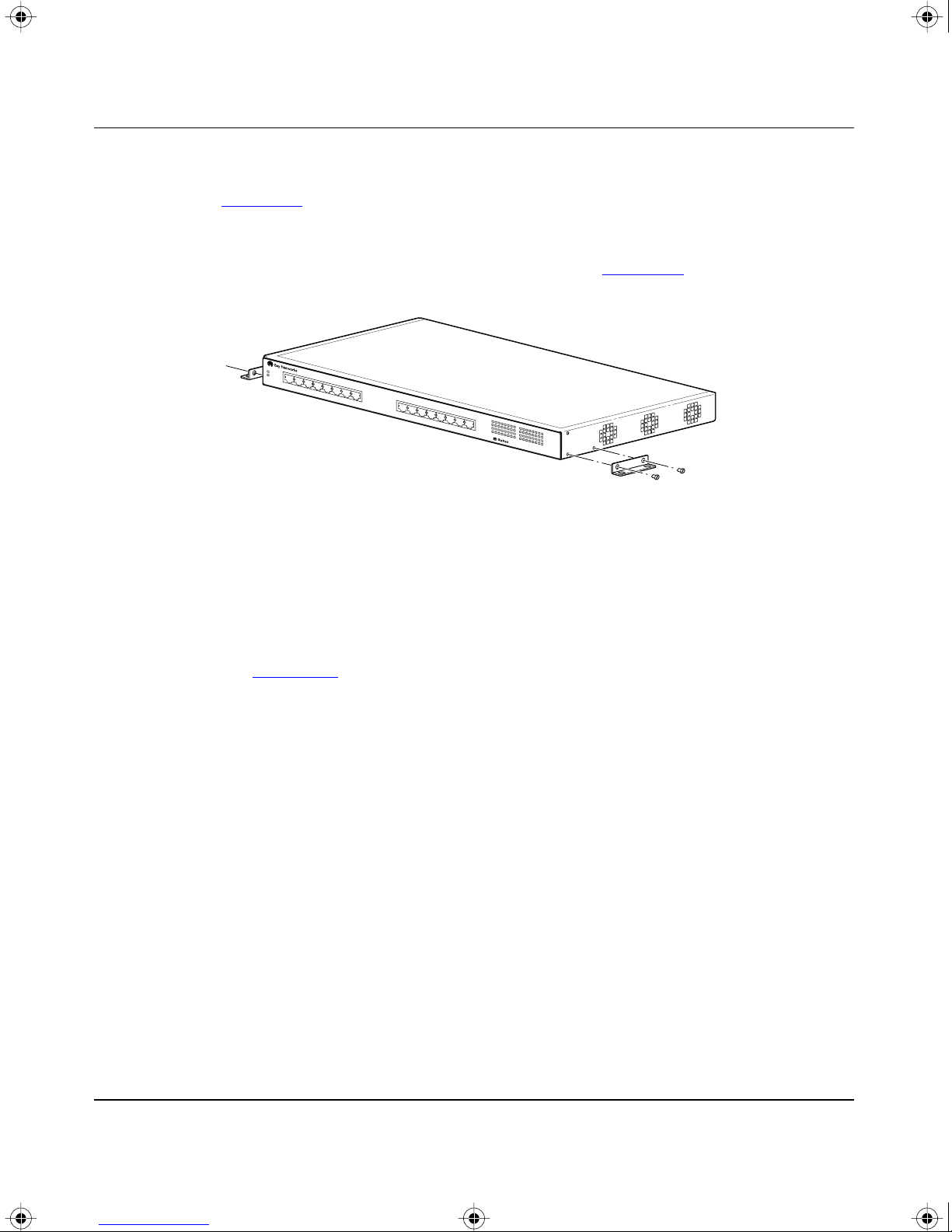
2-2 shows the mounting bracket positions for surface mounting the
BayStack 350T switch onto a flat surface such as a tabletop, shelf, or wall. When
rack mounting the switch, the same brackets are used, but they are positioned to
attach to the rack mount holes in the chassis (see Figure
350T
10/100 Autosense Switch
Figure 2-2. Attaching mounting brackets for a surface mount
2-5).
585FA
To install the mounting brackets for surface mount configurations, follow these
steps:
1. Locate the surface mounting holes on both sides of the switch (see
e 2-2).
Figur
2. Using a Phillips (or cross-head) screwdriver, attach the two mounting
brackets to both sides of the switch with the four screws supplied with the
unit.
3. Attach the switch to the tabletop, shelf, or wall as described in the
appropriate section.
2-6 893-00992-A
Page 55
BOOK.MKR Page 7 Tuesday, March 4, 1997 7:24 PM
Tabletop or Shelf Installation
To install the BayStack 350T switch onto a tabletop or shelf, follow these steps:
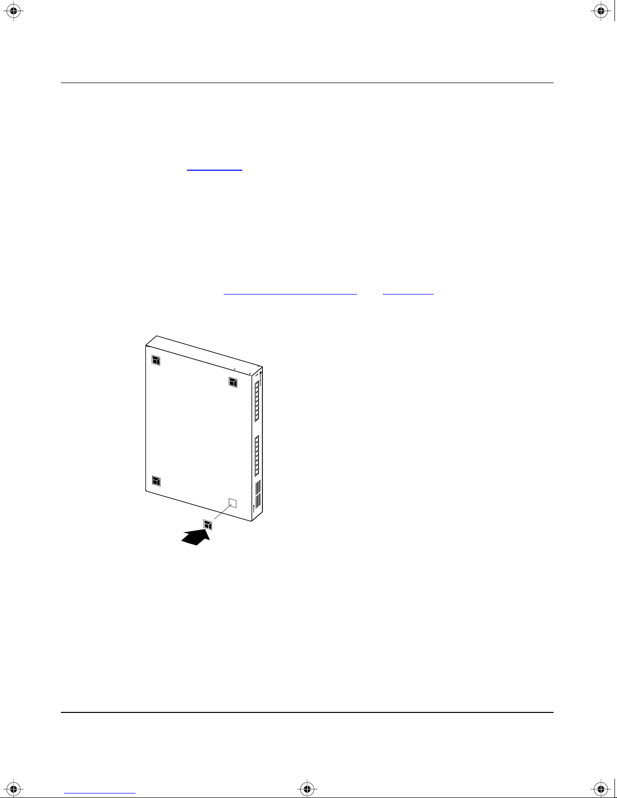
1. Attach four rubber footpads onto the bottom of the unit, at each corner
(see Figur
2. Place the switch onto the tabletop or shelf with the front panel facing
toward you. Be sure to leave adequate space around the unit for
ventilation and access to the cables.
3. If you are securing the switch to the tabletop or shelf, insert two screws
(not supplied) through each of the mounting brackets and tighten the
screws.
4. Proceed to “Connecting Port Cables” on page 2-11 to connect the
network cables.
Installation
e 2-3).
Figure 2-3. Attaching rubber footpads
893-00992-A 2-7
310T
586FA
Page 56

BOOK.MKR Page 8 Tuesday, March 4, 1997 7:24 PM
Using the BayStack Model 350T 10/100 Autosense Switch
Wall Mounting
The BayStack 350T switch can be installed onto any wall that can safely support
the weight of the device and attached cables (see “
for safety considerations). The BayStack 350T switch can be mounted with or
without the rubber footpads attached.
Before Mounting the BayStack 350T Switch to a Wall
Before installing the BayStack 350T switch onto the wall, take note of the
following considerations that apply to wall mounting:
• The BayStack 350T switch can only be wall mounted with the front panel
facing upward, as shown in Figure
Site Preparation” on page 2-3
2-4.
• Because the LEDs are located on the front panel, you should position the
switch at a height that allows the LEDs to remain visible at all times.
• Do not allow attached port cables to hang freely from the port connectors.
Instead, install plastic cable clamps appropriately to support and dress the
cables.
• Because wall compositions vary at each site, wall mounting screws are not
provided. You should choose the appropriate size mounting hardware
according to your wall composition.
• A common and safe method for attaching devices to most wall types is to
attach the device to a piece of plywood (at least 0.5 in. thick) that is firmly
secured to the wall, preferably to the wall studs.
2-8 893-00992-A
Page 57
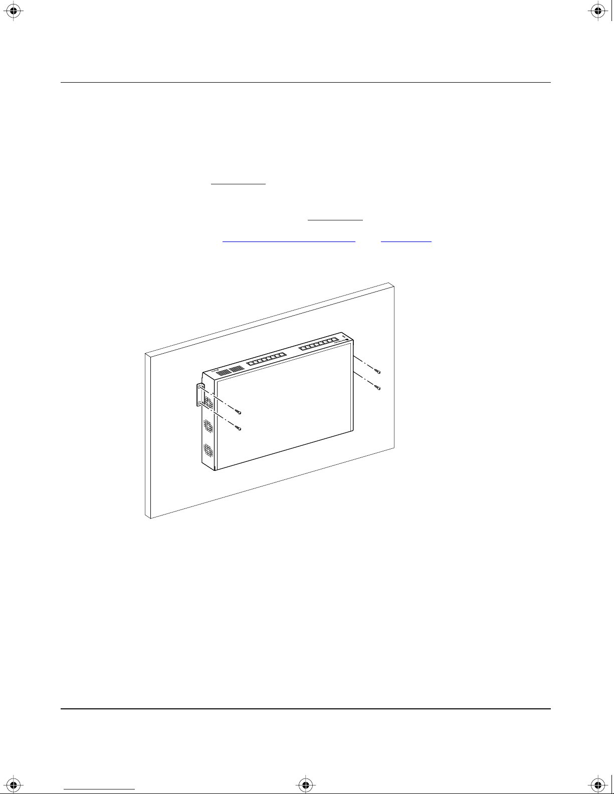
BOOK.MKR Page 9 Tuesday, March 4, 1997 7:24 PM
Wall Mounting the Switch
To install the BayStack 350T switch onto a wall, follow these steps:
1. Using a Phillips (or cross-head) screwdriver, attach the two mounting
brackets to both sides of the switch with the four screws supplied with the
unit (see Figur
2. Insert two screws (not supplied) through each of the mounting brackets
and tighten the screws (see Figur
3. Proceed to “Connecting Port Cables” on page 2-11 to connect the
network cables.
Installation
e 2-2).
e 2-4).
310T
587FA
Figure 2-4. Attaching a BayStack 350T switch to a wall
893-00992-A 2-9
Page 58
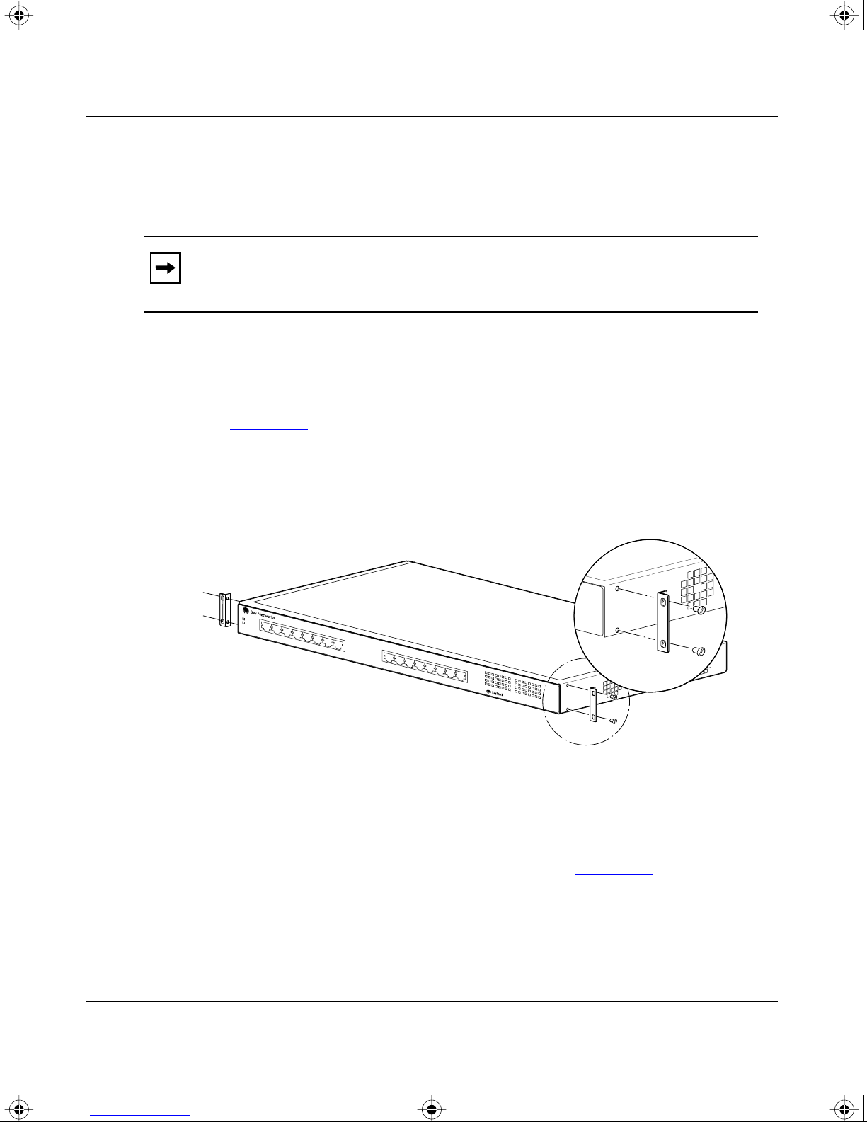
BOOK.MKR Page 10 Tuesday, March 4, 1997 7:24 PM
Using the BayStack Model 350T 10/100 Autosense Switch
Rack Mounting
The BayStack 350T switch occupies one single-unit rack space and can be
installed in most standard 19-inch racks.
Note: When rack mounting the BayStack 350T switch, do not attach the four
rubber footpads supplied with the unit. If your unit already has the rubber
footpads attached, remove them before installing the switch in the rack.
To install the BayStack 350T switch in a 19-inch rack, follow these steps:
1. If the switch has rubber footpads on the bottom of the unit, remo v e them.
2. Locate the rack mounting holes on both sides of the switch (see
e 2-5).
Figur
3. Using a Phillips (or cross-head) screwdriver, attach the two mounting
brackets to both sides of the switch with the four screws supplied with the
unit.
witch
350T
10/100 Autosense Switch
610FA
Figure 2-5. Attaching mounting brackets for a rack mount
Position the switch in the rack and align the holes in the mounting
4.
bracket with the holes in the rack chassis (see Figur
e 2-6).
5. Insert two screws, appropriate for your 19-inch rack, into each of the
mounting brackets and tighten with a suitable screwdriver.
6. Proceed to “Connecting Port Cables” on page 2-11 to connect the
network cables.
2-10 893-00992-A
Page 59
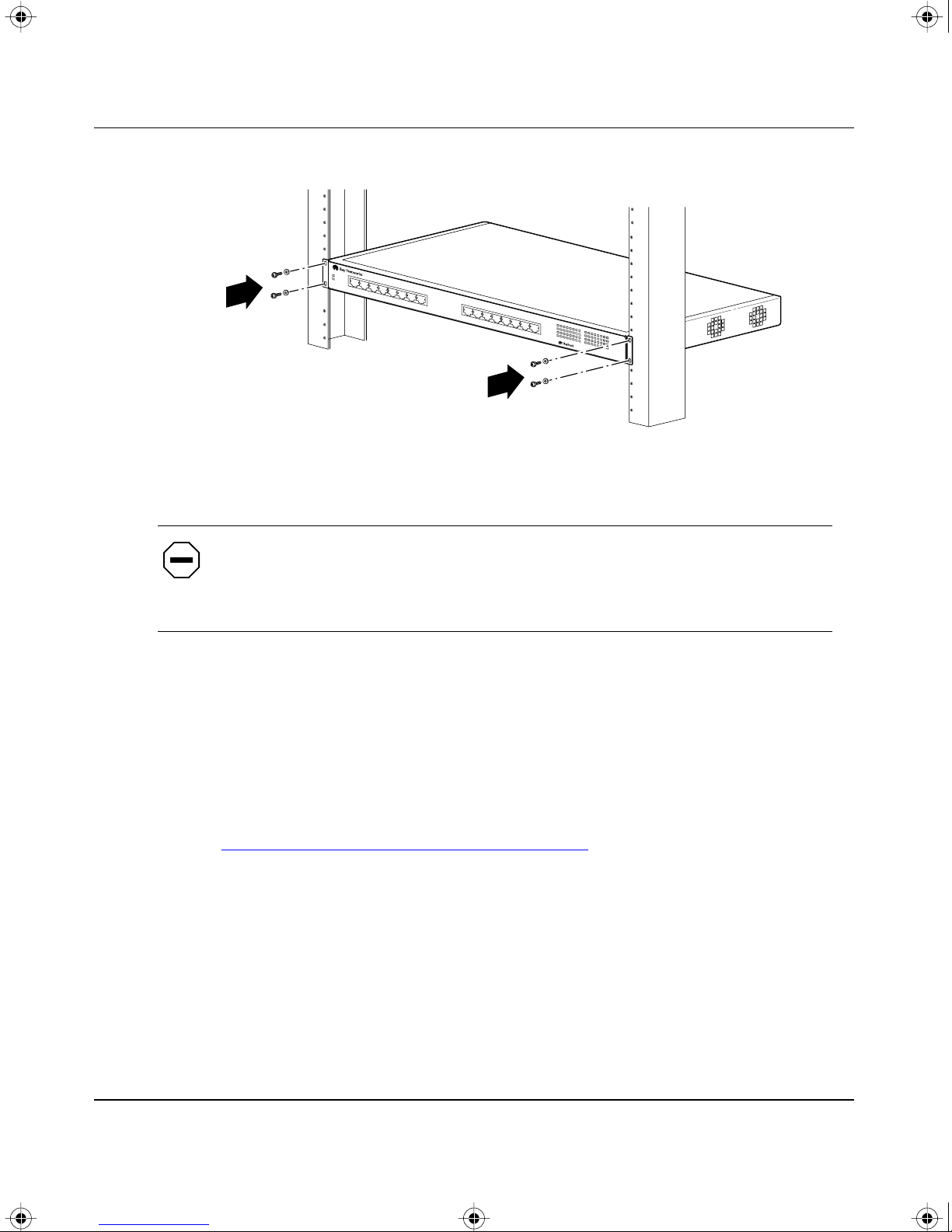
BOOK.MKR Page 11 Tuesday, March 4, 1997 7:24 PM
350T
Installation
10/100 Autosense Switch
611FA
Figure 2-6. Installing the BayStack 350T switch in a 19-inch rack
Caution: When mounting this device in a rack, do not stack units directly on
top of one another in the rack. Each unit must be secured to the rack with
appropriate mounting brackets. Mounting brackets are not designed to support
multiple units.
Connecting Port Cables
The switch ports are configured with RJ-45 (10BASE-T/100BASE-TX)
connectors that are wired as MDI-X ports. As in conventional Ethernet repeater
hubs, the BayStack 350T switch ports connect over straight-through cables to the
network interface controller (NIC) card in a node or server. When connecting to
an Ethernet hub or to another switch, you must use a crossover cable. Refer to
Appendix
By default, all of the BayStack 350T switch ports are set with the autonegotiation
feature enabled. This feature allows an y port to match the best service provided by
the connected station, up to 100 Mb/s at full-duplex mode.
B, “Connectors and Pin Assignments,” for more information.
893-00992-A 2-11
Page 60
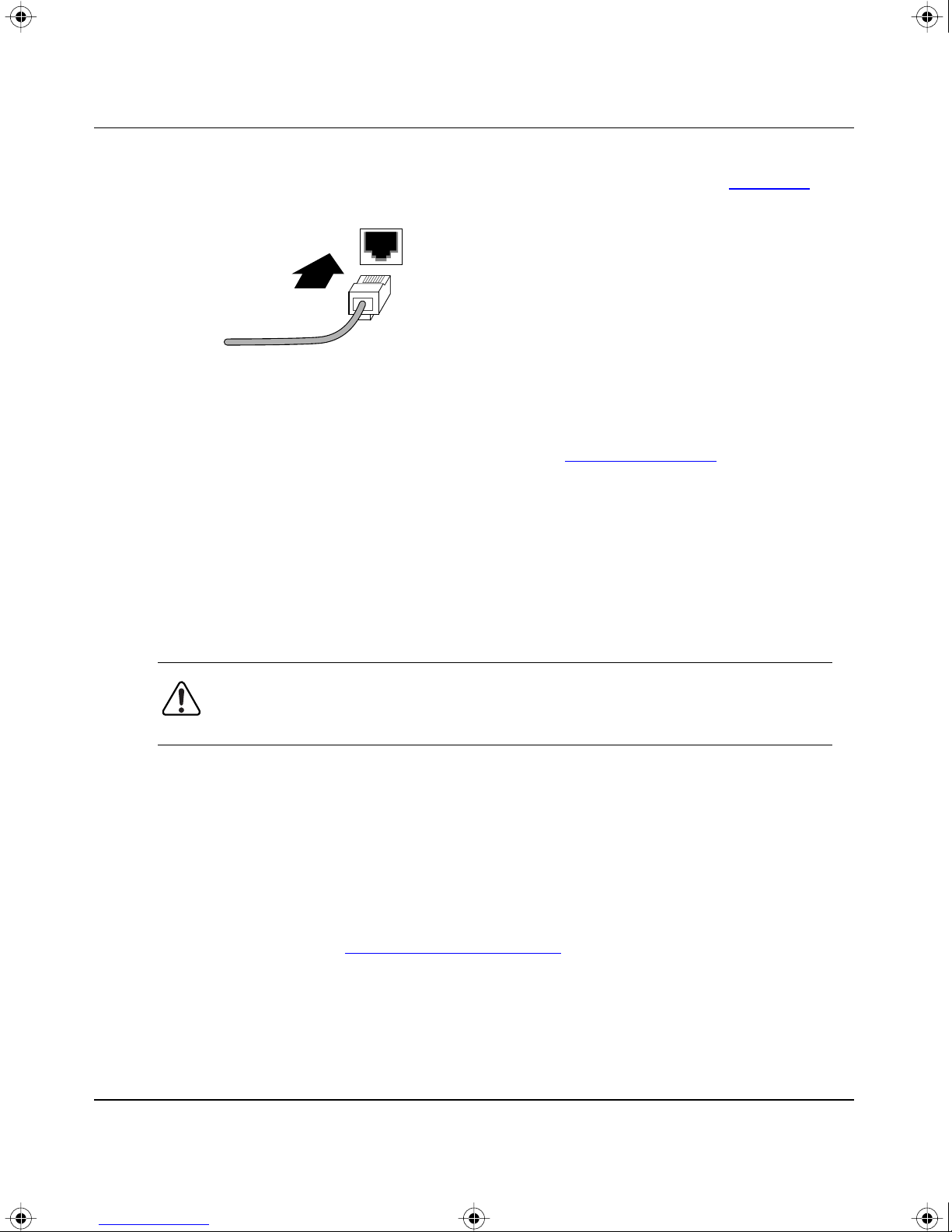
BOOK.MKR Page 12 Tuesday, March 4, 1997 7:24 PM
Using the BayStack Model 350T 10/100 Autosense Switch
To connect the port cables, insert the cable plug into the appropriate port
connector until the release tab snaps into the locked position (see Figure
Figure 2-7. Connecting a port cable to the BayStack 350T switch
After connecting the port cables, proceed to “Connecting Power” to connect the
AC power cord and power up the BayStack 350T switch.
2-7).
5634
Connecting Power
The BayStack 350T switch does not have a power on/off switch. When you
connect the AC power cord to a suitable AC outlet, the switch powers up
immediately.
Warning: Removal of the po wer cord is the only w ay to turn off power to this
device. The power cord must always be connected in a location that can be
accessed quickly and safely in case of an emergency.
To connect the BayStack 350T switch AC power cord, complete the following
steps:
1. Plug one end of the switch AC power cord into the switch AC power
receptacle, located on the back panel.
2. Plug the other end of the AC power cord into a grounded AC power
outlet.
3. Proceed to “Verifying the Installation” to verify proper operation.
2-12 893-00992-A
Page 61
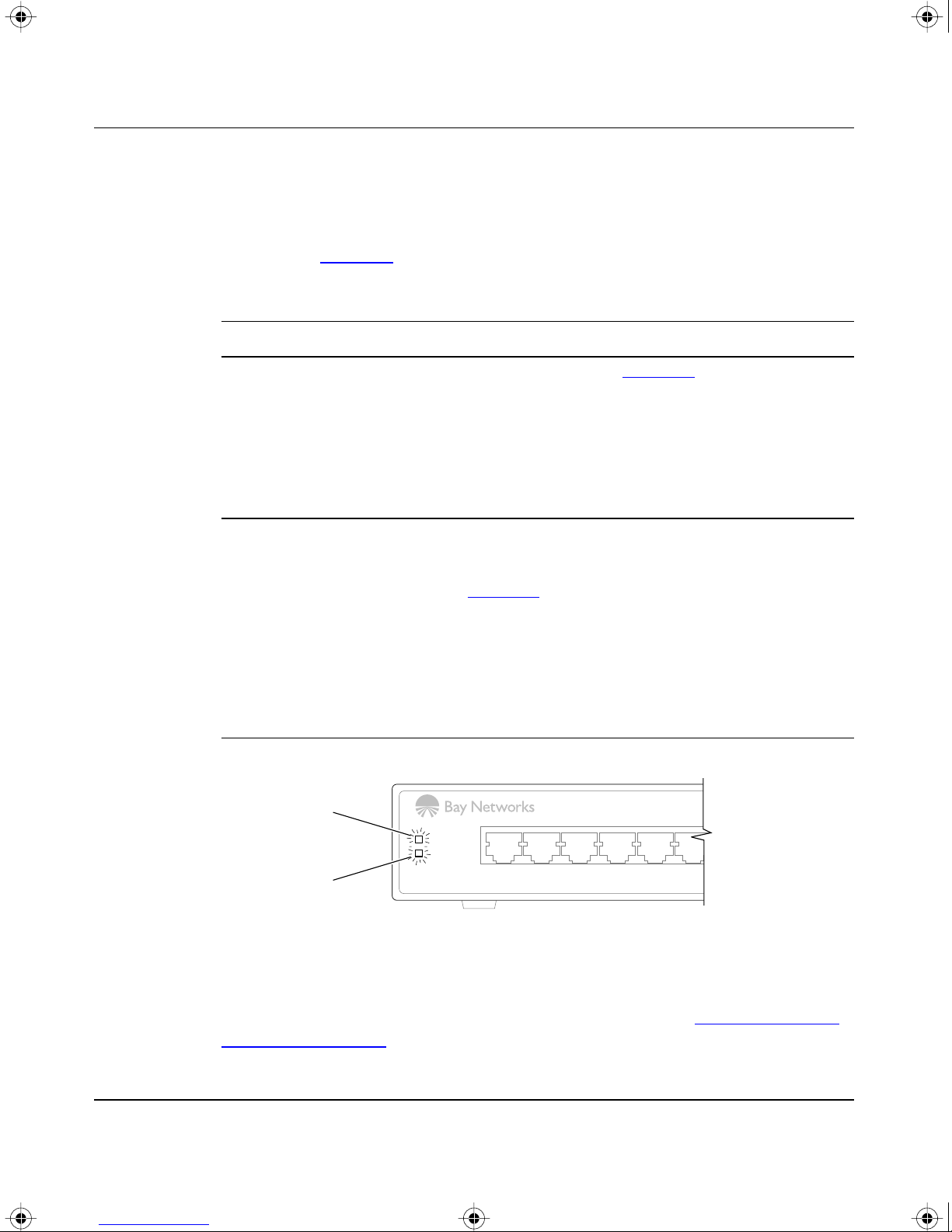
BOOK.MKR Page 13 Tuesday, March 4, 1997 7:24 PM
Verifying the Installation
Proper operation of the BayStack 350T switch is verified by observing the front
panel LEDs. During the power-up sequence, the LEDs display the sequence
described in T
Table 2-1. Power-up sequence of the BayStack 350T switch
Stage Description Indication
Installation
able 2-1.
1 Immediately after
AC power is
applied to the unit,
DC power is
available to the
switch’s internal
circuitry.
2 The switch initiates
its built-in self test.
Power LED
The Power LED lights (see Figure
2-8).
If the Pow er LED does not light, verify that power is a vailab le
at the AC outlet and that the power cable is securely
fastened at both ends.
If the Power LED still does not light, contact the sales agent
or the customer service representative where you
purchased your BayStack 350T switch.
As subroutines are initiated by the self-test, the port status
LEDs flash various patterns. When the switch passes the
self-test (within 10 seconds), the Diagnostics LED lights
(see Figure
2-8).
If a nonfatal error occurs during self-test, the Diagnostics
LED blinks.
If the switch fails the self-test, the Diagnostics LED remains
off. Contact the sales agent or the customer service
representative where you purchased your BayStack 350T
switch.
123456
Power
Diagnostics
Diagnostics LED
Figure 2-8. Observing LEDs to verify correct operation
After verifying the BayStack 350T switch operation, refer to Chapter 3, “Using
the Console Interface” to configure and manage the switch using the console
interface.
893-00992-A 2-13
613EA
Page 62

BOOK.MKR Page 14 Tuesday, March 4, 1997 7:24 PM
Page 63

BOOK.MKR Page 1 Tuesday, March 4, 1997 7:24 PM
Overview
This chapter describes how to configure and manage the BayStack Model 350T
10/100 Autosense Switch using the menu-driven console interface (CI). You can
access the CI menu screens through the service port located on the switch back
panel. You can also manage the BayStack 350T switch with Optivity network
management software or with a generic SNMP-based management application;
however, you must first assign an IP address to the switch, as described in this
chapter . If you hav e a BootP serv er that is correctly set up on your network, the IP
address for the BayStack 350T switch will be detected and you do not have to
manually assign the IP address.
Chapter 3
Using the Console Interface
Note: Refer to your network management documentation for information
about SNMP network management.
CI Description
The console interface (CI) consists of menus and screen displays that enable you
to manage the BayStack 350T switch and monitor its performance. You can
manage the switch by using configuration menus to change its operational
parameters. You can monitor the performance of the switch through the statistics
screen, which displays the counters of the switch ports.
You can access the CI menus in the following ways:
• Locally, through a console terminal (must be a VT100-compatible terminal or
a PC running VT100 terminal-emulation software)
• Remotely, through a dial-up modem connection
• Through an in-band TELNET session
893-00992-A 3-1
Page 64
BOOK.MKR Page 2 Tuesday, March 4, 1997 7:24 PM
Using the BayStack Model 350T 10/100 Autosense Switch
Service Port Cabling
You can connect a console terminal directly to the BayStack 350T switch service
port or you can connect a modem to the switch service port for remote access to
the CI menus.
Note: To ensure correct connections between the service port and the console
or modem port, refer to the service port pin assignments in Appendix
“Connectors and Pin Assignments.”
Console T erminal Requirements
T o connect a console terminal to the BayStack 350T switch service port, you need
the following equipment:
B,
• An ASCII character terminal that has an RS-232 serial port or a computer that
has an RS-232 serial port and terminal emulation, typically a PC running
common communications software
• A standard RS-232 serial communications cable with a DB-9 connector at
one end for connection to the service port and an appropriate connector
(usually a DB-9 or DB-25 connector) at the other end for connection to the
serial port on the console terminal
Modem Requirements
To connect a modem to the BayStack 350T switch service port, you need the
following equipment:
• A 9600 baud (or higher speed) modem is recommended. The service port
speed is set to 9600 baud (default factory setting) but supports 2400 baud
through 38400 baud, as long as the speed at both ends of the communications
link are identical.
• A standard RS-232 serial communications null-modem cable with a DB-9
connector at one end for connection to the service port and an appropriate
connector (usually a DB-9 or DB-25 connector) at the other end for
connection to the serial port on the modem is required.
Set the modem’s serial port speed to match the speed of the BayStack 350T
service port (9600 baud is the default). See “
3-32 to modify the switch service port.
page
3-2 893-00992-A
Service Port Configuration” on
Page 65

BOOK.MKR Page 3 Tuesday, March 4, 1997 7:24 PM
Connecting to the BayStack 350T Switch Service Port
To connect a console terminal or modem to the BayStack 350T switch service
port, follow these steps:
1. Plug the RS-232 cable DB-9 receptacle into the service port plug. Secure
the connection with the two screws on the DB-9 receptacle.
2. Plug the other end of the RS-232 cable (DB-9 or DB-25, as appropriate)
into the console terminal or modem RS-232 serial port.
Accessing the CI Menus
You can access the CI menus through a local console terminal, remotely through a
dial-up modem connection, or through a TELNET session.
Using the Console Interface
To access the CI menus through a TELNET session, your workstation must be
configured with an IP address, and you must know the IP address of the switch in
order to establish a link. You can configure an IP address for the BayStack 350T
switch using a console terminal (as described in this section). If you have a BootP
server on your network, the IP address for the switch will be detected and you will
not have to configure the IP address. Refer to your TELNET documentation for
information about establishing TELNET connections.
To access the CI menus, complete the following steps:
1. Power up the console terminal, or make sure that your PC is running in
terminal-emulation mode.
2. Set the console terminal configuration parameters as follows:
• 9600 baud
• 8 data bits
• no parity
• 1 stop bit
3. Place the console terminal online; do not leave it in setup mode.
4. Press [Ctrl]+C on the console terminal keyboard.
The CI Main Menu appears on the screen; for more information about using
the CI Main Menu, proceed to “
893-00992-A 3-3
Using the CI Menus.”
Page 66

BOOK.MKR Page 4 Tuesday, March 4, 1997 7:24 PM
Using the BayStack Model 350T 10/100 Autosense Switch
Using the CI Menus
The CI menus and screens provide commands that allow you to configure and
manage the BayStack 350T switch.
Although some commands carry out actions immediately, other commands are
followed by an ellipsis (for example, IP Configuration...) indicating that the
selection displays a submenu with other options.
Some commands can switch between several possible settings; these commands
toggle a condition. Other commands allow you to enter information; these
commands set or modify a parameter.
Navigating the CI Menus
Use the following methods to navigate the CI menus:
• To select a command:
— Use the arrow keys to highlight the command name.
— Press [Enter].
Alternatively, you can press the key corresponding to the underlined letter in
the command name. For example, to select the Sw
itch Configuration
command in the Main Menu, press the [W] key. Note that the text characters
are not case sensitive.
• To toggle between several possible settings:
— Use the Space bar to highlight the setting.
— Press [Enter].
• To clear a string field:
— Place the cursor in the string field.
— Press [Ctrl]+K.
• To return to the previous menu, press [Ctrl]+R.
• To return to the Main Menu at any time, press [Ctrl]+C.
3-4 893-00992-A
Page 67
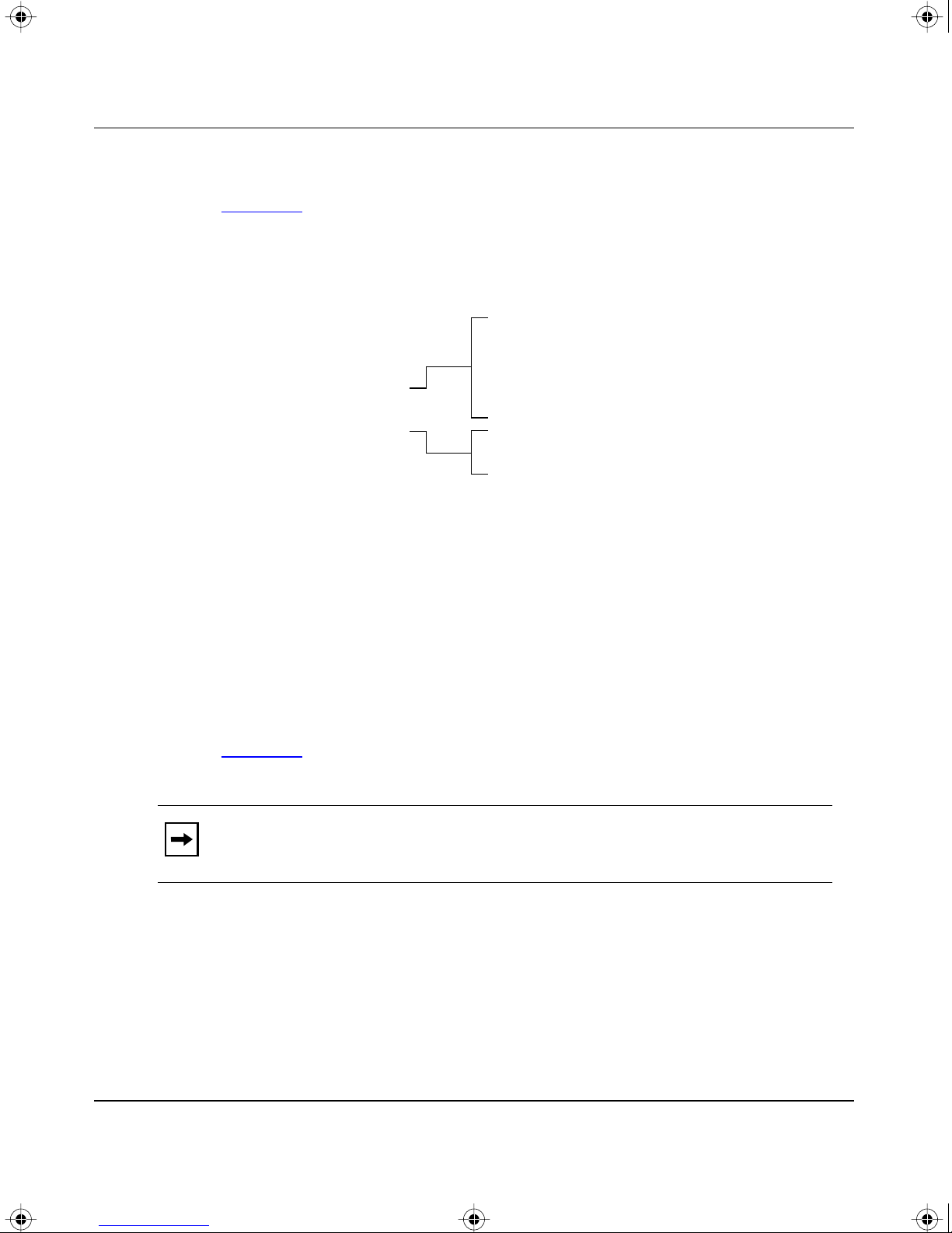
BOOK.MKR Page 5 Tuesday, March 4, 1997 7:24 PM
Screen Fields and Descriptions
Figure 3-1 shows a map of the CI screens. The remainder of this chapter describes
the CI screens, including each of the corresponding screen fields, beginning with
the Main Menu.
IP Configuration
SNMP Configuration
System Characteristics
Switch Configuration
Service Port Configuration
Spanning Tree Configuration
Telnet Configuration
Software Download
Display Event Log
Reset to Default Settings
Using the Console Interface
Main Menu
MAC Address Table
VLAN Configuration
Port Configuration
Display Port Statistics
Clear Port Statistics
Spanning Tree Port Configuration
Display Spanning Tree Switch Settings
Reset
Logout
614EA
Main Menu
Figure 3-1. Map of console interface Main Menu screens
This section describes the commands available from the Main Menu (see
Figure
3-2). The submenus for these commands are described in the following
sections.
Note: The field values and settings shown in the screen displays throughout
this section are provided as examples only.
893-00992-A 3-5
Page 68

BOOK.MKR Page 6 Tuesday, March 4, 1997 7:24 PM
Using the BayStack Model 350T 10/100 Autosense Switch
BayStack Model 350T Main Menu
I
SNM
S
Sw
Serv
Sp
T
Sof
Display E
R
Reset to D
L
Use arrow keys to highlight option, press <Return> or <Enter> to select option.
P Configuration...
P Configuration...
ystem Characteristics...
itch Configuration...
ice Port Configuration...
anning Tree Configuration...
ELNET Configuration...
tware Download...
vent Log
eset
efault Settings
ogout
Figure 3-2. CI Main Menu
The CI Main Menu includes the commands listed in Table 3-1.
Table 3-1. CI Main Menu commands
Command Description
IP Configuration... Displays the IP Configuration screen (see “IP Configuration” on
page
3-8). The IP Configuration screen allows you to set or modify IP
configuration parameters.
SNMP Configuration... Displays the SNMP Configuration screen (see “SNMP Configuration” on
page
3-13). This screen allows you to set or modify the SNMP read-only
community and read-write community strings, to enable or disable the
authentication trap, to set the IP address of trap receiv ers , and to set the
trap community strings.
System Characteristics... Displays the System Characteristics screen (see “
Characteristics” on page 3-15). This screen allows you to view switch
characteristics such as the number of resets and the hardware and
firmware version. This screen also contains three user-configurable
fields: sysContact, sysName, and sysLocation.
System
3-6 893-00992-A
Page 69

BOOK.MKR Page 7 Tuesday, March 4, 1997 7:24 PM
Table 3-1. CI Main Menu commands (continued)
Command Description
Switch Configuration... Displays the Switch Configuration Menu (see “Switch Configuration” on
Using the Console Interface
page
3-17). This menu provides additional configuration commands. The
commands include: MAC Address Table, VLAN Configuration, Port
Configuration, and Display Port Statistics.
Service Port Configuration... Displays the Service Port Configuration screen (see “
Service Port
Configuration” on page 3-32).
Spanning T ree Configuration... Displays the Spanning Tree Configuration Menu (see “
Spanning Tree
Configuration Menu” on page 3-34).
TELNET Configuration... Displays the TELNET Configuration screen (see “
TELNET
Configuration” on page 3-41).
Software Download... Displays the Software Download screen (see “
page
3-44).
Display Event Log Displays the Event Log screen (see “
Display Event Log” on page 3-47).
Software Download” on
Reset Resets the switch with the current configuration settings. When this
command is selected, the switch resets, runs a self-test, and displays the
Main Menu.
Reset to Default Settings Resets the switch with factory default configuration settings. When this
command is selected, the switch resets, runs a self-test, and displays the
Main Menu.
Caution: If you choose the Reset to Default Settings command, all of
your configured settings will be replaced with factory default settings
when you press [Enter].
Logout The Logout command allows a user at a password-protected console
terminal or an active TELNET session to disconnect the session (see
“
Logout” on page 3-51).
893-00992-A 3-7
Page 70
BOOK.MKR Page 8 Tuesday, March 4, 1997 7:24 PM
Using the BayStack Model 350T 10/100 Autosense Switch
IP Configuration
The IP Configuration screen (see Figure 3-3) allows you to set or modify the
BayStack 350T switch IP configuration parameters. Data entered into the
configurable fields of the screen display take effect as soon as the user presses
[Enter].
Note: The read-only fields in this screen are updated depending on the BootP
mode selected in the BootP Request Mode: field (see “
Request Mode” in this section for more information).
Choosing a BootP
IP Configuration
BootP Request Mode: [ BootP When Needed ]
Configurable In Use Last BootP
------------------- --------------- --------------In-Band IP Address: [ 0.0.0.0 ] 0.0.0.0 0.0.0.0
In-Band Subnet Mask: [ 0.0.0.0 ] 0.0.0.0 0.0.0.0
Default Gateway: [ 0.0.0.0 ] 0.0.0.0 0.0.0.0
Press Ctrl-R to return to previous menu. Press Ctrl-C to return to Main Menu.
Figure 3-3. IP Configuration screen
3-8 893-00992-A
Page 71

BOOK.MKR Page 9 Tuesday, March 4, 1997 7:24 PM
The IP Configuration screen includes the fields listed in Table 3-2.
Table 3-2. IP Configuration screen fields
Field Description
BootP Request Mode: Sets one of four modes of operation f or the BootP protocol (see “Choosing a BootP
Request Mode” on page 3-10 for details about the four modes you can choose).
Default V alue: BootP When Needed
Range: BootP When Needed, BootP Always, BootP Disabled, BootP or
Configurable Column header for the (user) Configurable fields in this screen.
In Use Column header for the read-only fields in this screen. The read-only data display ed
in this column represents data that is currently in use.
Last BootP Column header f or the read-only fields in this screen. The read-only data generated
in this column represents data obtained from the last BootP reply received.
Using the Console Interface
Last Address
In-Band IP Address: The in-band IP address of the BayStack 350T switch.
Default Value: 0.0.0.0 (no IP address assigned)
Range: Four-octet decimal IP address notation, where each octet of the
address is represented as a decimal value, separated b y a decimal
point
In-Band Subnet
Mask:
Default Gateway: The IP address of the default gateway.
Contains the subnet address mask that is associated with the in-band IP address
shown on the screen.
The subnet mask is used by network routers to determine the network or subnet
address portion of a host’s IP address. The bits in the IP address that contain the
network address (including the subnet), are set to 1 in the address mask, and bits
that contain the host identifier are set to 0.
Default Value: 0.0.0.0 (no subnet mask assigned)
Range: Four-octet decimal IP address notation, where each octet is
represented as a decimal value, separated by a decimal point
Default Value: 0.0.0.0 (no IP address assigned)
Range: Four-octet decimal IP address notation, where each octet is
represented as a decimal value, separated by a decimal point
893-00992-A 3-9
Page 72

BOOK.MKR Page 10 Tuesday, March 4, 1997 7:24 PM
Using the BayStack Model 350T 10/100 Autosense Switch
Choosing a BootP Request Mode
The BootP Request Mode field (in the IP Configuration screen) allows you to
choose one of the following methods for the switch to broadcast BootP requests:
• BootP When Needed
• BootP Al ways
• BootP Disabled
• BootP or Last Address
The following sections describe the BootP Request Modes.
BootP When Needed
This mode field setting allows the switch to request an IP address if it is not
already configured into the switch from the console terminal.
When selected, this field operates as follows:
• When the IP data is entered from the console terminal, the entered data
becomes the in-band address of the switch and BootP requests are not
broadcast. The switch can be managed in-band using this in-band IP address.
• When the in-band IP address is not set from the console terminal, the switch
broadcasts BootP requests until a BootP reply containing an IP address is
received. If the switch does not receive a BootP reply that contains an IP
address, it cannot be managed in-band.
If an IP address is not currently in use, these actions take effect immediately.
If an IP address is currently in use, these actions take effect only after the switch is
reset or power cycled.
3-10 893-00992-A
Page 73

BOOK.MKR Page 11 Tuesday, March 4, 1997 7:24 PM
BootP Always
This mode field setting allows the switch to be managed only when configured
with the IP address obtained from the BootP server.
When selected, this field operates as follows:
• The switch continues to broadcast BootP requests, regardless of whether an
in-band IP address is set from the console terminal.
• If the switch receives a BootP reply that contains an in-band IP address, the
switch uses this new in-band IP address.
• If a reply is not received, the switch cannot be managed with the in-band IP
address set from the console terminal.
If an IP address is not currently in use, these actions take effect immediately.
Using the Console Interface
If an IP address is currently in use, these actions take effect only after the switch is
reset or power cycled.
BootP Disabled
This mode field setting allows the switch to be manageable only by using the IP
address set from the console terminal.
When selected, this field operates as follows:
• The switch does not broadcast BootP requests, regardless of whether an IP
address is set from the console terminal.
• The switch is manageable only when using the in-band IP address set from
the console terminal.
These actions take effect after the switch is reset or power cycled, even if an IP
address is not currently in use.
893-00992-A 3-11
Page 74

BOOK.MKR Page 12 Tuesday, March 4, 1997 7:24 PM
Using the BayStack Model 350T 10/100 Autosense Switch
BootP or Last Address
This mode field setting allows the switch to continue to be manageable, even
though a BootP server may not currently be reachable.
When selected, this field operates as follows:
• When the IP data is entered from the console terminal, the entered data
becomes the in-band address of the switch, and BootP requests are not
broadcast. The switch can be managed using this in-band IP address.
• When the in-band IP address is not set from the console terminal, the switch
broadcasts BootP requests until a BootP reply containing an in-band IP
address is received. If the switch does not receive a BootP reply that contains
an in-band IP address within 10 minutes, the switch uses the last in-band IP
address that was received from a BootP server. This IP information is
displayed under the Last BootP column header.
If an IP address is not currently in use, these actions take effect immediately.
If an IP address is currently in use, these actions take effect only after the switch is
reset or powe cycled.
3-12 893-00992-A
Page 75

BOOK.MKR Page 13 Tuesday, March 4, 1997 7:24 PM
SNMP Configuration
The SNMP Configuration screen (see Figure 3-4) allows you to set or modify
your SNMP configuration parameters.
Read-Only Community String: [ public ]
Read-Write Community String: [ private ]
Trap #1 IP Address: [ 0.0.0.0 ]
Community String: [ ]
Trap #2 IP Address: [ 0.0.0.0 ]
Community String: [ ]
Trap #3 IP Address: [ 0.0.0.0 ]
Community String: [ ]
Trap #4 IP Address: [ 0.0.0.0 ]
Community String: [ ]
Using the Console Interface
SNMP Configuration
Authentication Trap: [ Enabled ]
Press Ctrl-R to return to previous menu. Press Ctrl-C to return to Main Menu.
Figure 3-4. SNMP Configuration screen
893-00992-A 3-13
Page 76

BOOK.MKR Page 14 Tuesday, March 4, 1997 7:24 PM
Using the BayStack Model 350T 10/100 Autosense Switch
The SNMP Configuration screen includes the fields listed in Table 3-3.
Table 3-3. SNMP Configuration screen fields
Field Description
Read-Only
Community String:
Read-Write
Community String:
Trap #1 IP Address: Number one of four allowed Trap IP Addresses. Successive Trap Address
Community String: The community string associated with one of the four allowed trap
Authentication T rap: Enables or disables sending a trap on an SNMP authentication failure.
The community string used for in-band read-only SNMP operations.
Default V alue: public
Range: Can be any ASCII string up to 32 printable characters
The community string used for in-band read-write SNMP operations.
Default V alue: private
Range: Can be any ASCII string up to 32 printable characters
fields are numbered #2, #3, and #4. Each of the Trap addresses has an
associated Community String (see next field description).
Default Value: 0.0.0.0 (no IP address assigned)
Range: Four-octet decimal IP address notation, where each
octet of the address is represented as a decimal value,
separated by a decimal point
addresses (see Trap #1 IP Address field description).
Default V alue: Zero-length string
Range: Can be any ASCII string up to 32 printable characters
Default V alue: Enabled
Range: Enabled, Disabled
3-14 893-00992-A
Page 77

BOOK.MKR Page 15 Tuesday, March 4, 1997 7:24 PM
System Characteristics
The System Characteristics screen (see Figure 3-5) allows you to view system
characteristics and contains three user-configurable fields: sysContact, sysName,
and sysLocation.
MAC Address: 00-60-FD-00-03-A8
Reset Count: 2
Last Reset Type: Software Download
Using the Console Interface
System Characteristics
sysDescr: BayStack Model 350T HW:RevC FW:V1.00 SW:V1.00
sysObjectID: 1.3.6.1.4.1.45.3.30.1.2
sysUpTime: 01:36:49
sysServices: 3
sysContact: [ M.J.Lento ]
sysName: [ Engineering Switch ]
sysLocation: [ Building 4, Floor 2 ]
Press Ctrl-R to return to previous menu. Press Ctrl-C to return to Main Menu.
Figure 3-5. System Characteristics screen
893-00992-A 3-15
Page 78

BOOK.MKR Page 16 Tuesday, March 4, 1997 7:24 PM
Using the BayStack Model 350T 10/100 Autosense Switch
The System Characteristics screen includes the fields listed in Table 3-4.
Table 3-4. System Characteristics screen fields
Field Description
MAC Address: The MAC address of the BayStack 350T switch.
Reset Count: Read-only field—indicates the number of resets since the BayStack 350T switch w as
originally loaded with operational firmware.
Default V alue: 1
Range: From 0 to 2
Last Reset Type: Read-only field—indicates the type of reset last initiated.
Default V alue: Power Cycle
Range: Power Cycle, Software Download, Management Reset,
32
–1
Management Factory Reset
sysDescr: Read-only field that specifies the hardware and software version.
sysObjectID: Read-only field that provides a unique identification of the device, containing the
vendor’s private enterprise number.
sysUpTime: Read-only field that shows the operational length of time since the last reset. Note:
This field is updated when the screen is redisplayed.
sysServices: Read-only field indicating device physical and data link layer functionality.
sysContact: The name and phone number of the person responsible for the switch.
Default V alue: Zero-length string
Range: Can be any ASCII string up to 56 printable characters
sysName: Any name that provides the switch with a unique identification.
Default V alue: Zero-length string
Range: Can be any ASCII string up to 56 printable characters
sysLocation: The physical location of the switch.
Default V alue: Zero-length string
Range: Can be any ASCII string up to 56 printable characters
3-16 893-00992-A
Page 79

BOOK.MKR Page 17 Tuesday, March 4, 1997 7:24 PM
Switch Configuration
The Switch Configuration Menu (see Figure 3-6) provides a choice of commands
you can use to set or modify your switch configuration.
Using the Console Interface
Switch Configuration Menu
M
V
P
D
C
R
Use arrow keys to highlight option, press <Return> or <Enter> to select option.
Press Ctrl-R to return to previous menu. Press Ctrl-C to return to Main Menu.
AC Address Table
LAN Configuration...
ort Configuration...
isplay Port Statistics
lear Port Statistics
eturn to Main Menu
Figure 3-6. Switch Configuration Menu
893-00992-A 3-17
Page 80

BOOK.MKR Page 18 Tuesday, March 4, 1997 7:24 PM
Using the BayStack Model 350T 10/100 Autosense Switch
The Switch Configuration Menu includes the commands listed in Table 3-5.
Table 3-5. Switch Configuration Menu commands
Command Description
MAC Address Table... Displays the MAC Address Table screen (see “MAC Address Table” on
page
by the switch.
VLAN Configuration... Displays the VLAN Configuration screen (see “VLAN Configuration” on
page
3-19). You can use this screen to view MAC addresses that were learned
3-20). You can use this screen to set up virtual LAN workgroups.
Port Configuration... Displays the Port configuration screen (see “
The Port Configuration screen allows you to selectively configure individual
switch ports or all switch port parameters.
Clear Port Statistics Displays the Clear Port Statistics screen (see “
page
3-31). The Clear Port Statistics screen allows you to reset accumulated
counters for a specific port or for all switch ports.
Display Port Statistics Displa ys the Port Statistics screen (see “P ort Statistics” on page 3-28). The Port
Statistics screen allows you to view detailed information related to any switch
port.
Return to Main Menu This command exits the Switch Configuration Menu and displays the Main
Menu.
Port Configuration” on page 3-26).
Clear Port Statistics on
3-18 893-00992-A
Page 81

BOOK.MKR Page 19 Tuesday, March 4, 1997 7:24 PM
MAC Address Table
The MAC Address Table screen (see Figure 3-7) allows you to view MAC
addresses that were learned by the switch. You can also use this screen to search
for specific MAC addresses.
Aging Time: [ 300 seconds ]
Find an Address: [ 00-00-00-00-00-00 ]
00-60-FD-00-03-A8
Using the Console Interface
MAC Address Table
End of Address Table. Press Ctrl-P to see previous display.
Press Ctrl-R to return to previous menu. Press Ctrl-C to return to Main Menu.
Figure 3-7. MAC Address Table screen
The MAC Address Table screen contains the fields listed in Table 3-6.
Table 3-6. MAC Address Table fields
Field Description
Aging Time: Specifies the length of time that a learned MAC address remains in the switch
forwarding database. If an entry is inactive during any time period that is longer than
the specified aging time, the entry is removed.
Default V alue: 300 seconds
Range: 00-00-00-00-00-00 to FF-FF-FF-FF-FF-FF
Find an Address: Allows user to search for specific existing MAC address.
Default Value: 00-00-00-00-00-00 (no MAC address assigned)
Range: 00-00-00-00-00-00
893-00992-A 3-19
Page 82

BOOK.MKR Page 20 Tuesday, March 4, 1997 7:24 PM
Using the BayStack Model 350T 10/100 Autosense Switch
VLAN Configuration
The VLAN Configuration screen (see Figure 3-8) allows you to configure your
BayStack 350T switch with as many as eight virtual LANs (VLANs). The screen
provides a matrix that allows you to group the switch ports into logical (virtual)
workgroups. Users within each of the logical workgroups can share resources but
cannot communicate with users in other logical workgroups.
Figure
3-8 shows the default setting for the VLAN Configuration screen, with all
16 ports configured in VLAN V1.
VLAN Configuration
Port V1 V2 V3 V4 V5 V6 V7 V8
---- ----- ----- ----- ----- ----- ----- ----- ---- 1 [ X ] [ ] [ ] [ ] [ ] [ ] [ ] [ ]
2 [ x ] [ ] [ ] [ ] [ ] [ ] [ ] [ ]
3 [ x ] [ ] [ ] [ ] [ ] [ ] [ ] [ ]
4 [ x ] [ ] [ ] [ ] [ ] [ ] [ ] [ ]
5 [ x ] [ ] [ ] [ ] [ ] [ ] [ ] [ ]
6 [ x ] [ ] [ ] [ ] [ ] [ ] [ ] [ ]
7 [ X ] [ ] [ ] [ ] [ ] [ ] [ ] [ ]
8 [ x ] [ ] [ ] [ ] [ ] [ ] [ ] [ ]
9 [ x ] [ ] [ ] [ ] [ ] [ ] [ ] [ ]
10 [ x ] [ ] [ ] [ ] [ ] [ ] [ ] [ ]
11 [ x ] [ ] [ ] [ ] [ ] [ ] [ ] [ ]
12 [ x ] [ ] [ ] [ ] [ ] [ ] [ ] [ ]
13 [ x ] [ ] [ ] [ ] [ ] [ ] [ ] [ ]
14 [ x ] [ ] [ ] [ ] [ ] [ ] [ ] [ ]
15 [ X ] [ ] [ ] [ ] [ ] [ ] [ ] [ ]
16 [ X ] [ ] [ ] [ ] [ ] [ ] [ ] [ ]
Use space bar to display choices, press <Return> or <Enter> to select choice.
Press Ctrl-R to return to previous menu. Press Ctrl-C to return to Main Menu.
Figure 3-8. VLAN Configuration screen
3-20 893-00992-A
Page 83
BOOK.MKR Page 21 Tuesday, March 4, 1997 7:24 PM
The switch ports can be configured into logical workgroups by simply selecting
the port numbers vertically, under the VLAN names. You can allow any port to be
shared by users on a separate VLAN by selecting the same port horizontally under
each VLAN name you want to connect.
You can create VLANs based on a single BayStack 350T switch, or you can create
VLANs that span multiple switches, but each switch participating in the VLAN
configuration must be configured separately.
You can also assign multiple VLANS to a port that is connected to a server,
thereby allowing the server to be shared among multiple logical workgroups.
Note: To share VLANs between two switches, one connection per VLAN is
required. Do not assign multiple VLANS to switch-to-switch connections.
Using the Console Interface
Example VLAN Configuration” on page 3-22 to see VLAN configuration
See “
screens set up for multiple BayStack 350T switches.
893-00992-A 3-21
Page 84
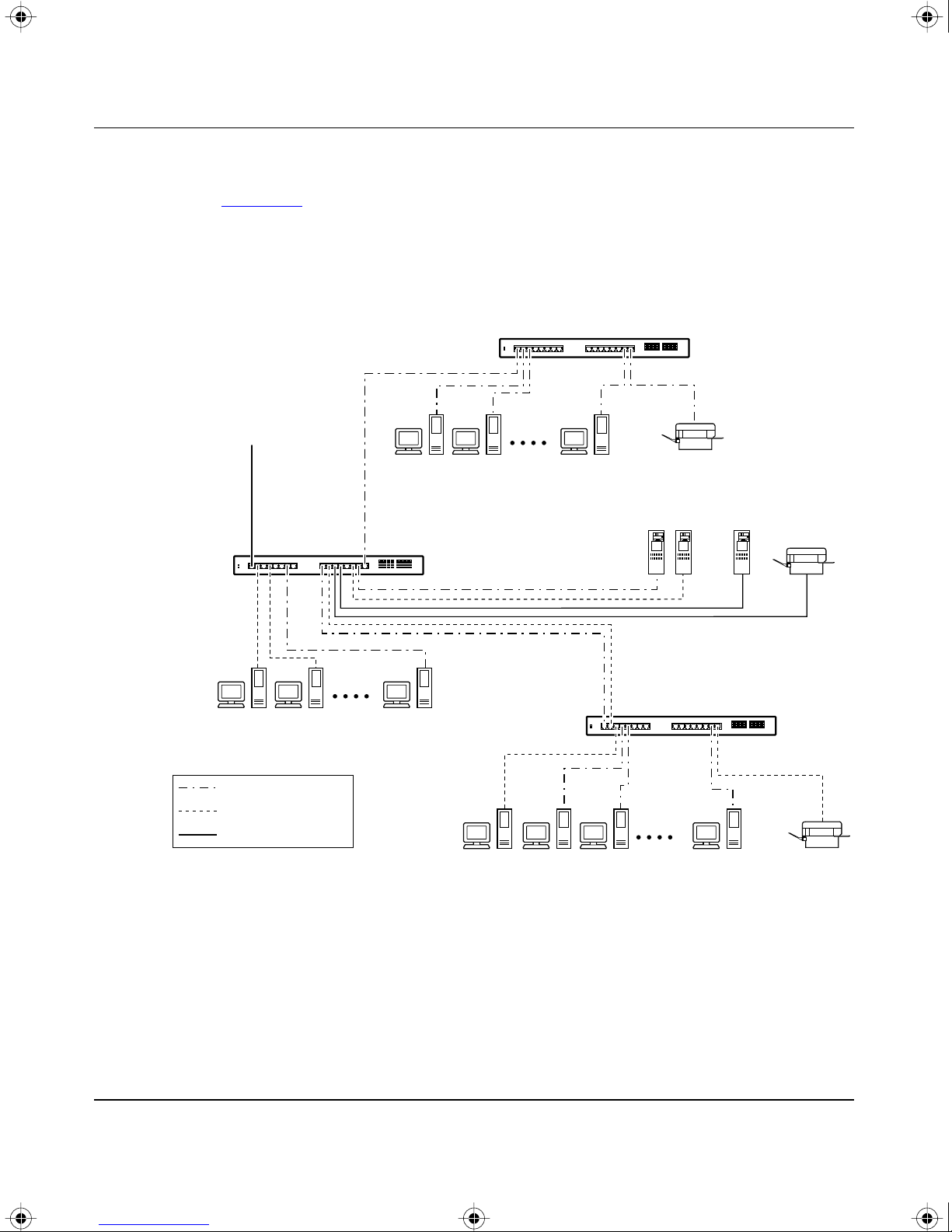
BOOK.MKR Page 22 Tuesday, March 4, 1997 7:24 PM
Using the BayStack Model 350T 10/100 Autosense Switch
Example VLAN Configuration
Figure
3-9 shows an example of a VLAN configuration that spans multiple
BayStack 350T switches. Each of the switches, S1, S2, and S3, are participants in
the VLAN configuration and are individually configured to create the VLAN
configuration shown here.
BayStack 350T switch
S2
To
network
center
V2
V1 + V2
S1
100 Mb/s
V1
BayStack 350T switch
BayStack 350T switch
S3
Key
VLAN1 V1
VLAN2 V2
VLAN V1 + V2
622EA
Figure 3-9. VLANs spanning multiple switches
3-22 893-00992-A
Page 85

BOOK.MKR Page 23 Tuesday, March 4, 1997 7:24 PM
Figure 3-10, Figure 3-11, and Figure 3-12 show the VLAN Configuration screen
settings used with each of the switches (S1, S2, and S3) shown in Figure
Port V1 V2 V3 V4 V5 V6 V7 V8
---- ----- ----- ----- ----- ----- ----- ----- ---- 1 [ X ] [ X ] [ ] [ ] [ ] [ ] [ ] [ ]
2 [ ] [ X ] [ ] [ ] [ ] [ ] [ ] [ ]
3 [ ] [ ] [ ] [ ] [ ] [ ] [ ] [ ]
4 [ ] [ x ] [ ] [ ] [ ] [ ] [ ] [ ]
5 [ ] [ ] [ ] [ ] [ ] [ ] [ ] [ ]
6 [ ] [ ] [ ] [ ] [ ] [ ] [ ] [ ]
7 [ X ] [ ] [ ] [ ] [ ] [ ] [ ] [ ]
8 [ ] [ ] [ ] [ ] [ ] [ ] [ ] [ ]
9 [ x ] [ ] [ ] [ ] [ ] [ ] [ ] [ ]
10 [ ] [ x ] [ ] [ ] [ ] [ ] [ ] [ ]
11 [ x ] [ x ] [ ] [ ] [ ] [ ] [ ] [ ]
12 [ x ] [ x ] [ ] [ ] [ ] [ ] [ ] [ ]
13 [ ] [ ] [ ] [ ] [ ] [ ] [ ] [ ]
14 [ ] [ X ] [ ] [ ] [ ] [ ] [ ] [ ]
15 [ X ] [ ] [ ] [ ] [ ] [ ] [ ] [ ]
16 [ X ] [ ] [ ] [ ] [ ] [ ] [ ] [ ]
Using the Console Interface
3-9.
VLAN Configuration
Use space bar to display choices, press <Return> or <Enter> to select choice.
Press Ctrl-R to return to previous menu. Press Ctrl-C to return to Main Menu.
Figure 3-10. VLAN Configuration screen for S1
893-00992-A 3-23
Page 86

BOOK.MKR Page 24 Tuesday, March 4, 1997 7:24 PM
Using the BayStack Model 350T 10/100 Autosense Switch
Port V1 V2 V3 V4 V5 V6 V7 V8
---- ----- ----- ----- ----- ----- ----- ----- ---- 1 [ X ] [ ] [ ] [ ] [ ] [ ] [ ] [ ]
2 [ x ] [ ] [ ] [ ] [ ] [ ] [ ] [ ]
3 [ x ] [ ] [ ] [ ] [ ] [ ] [ ] [ ]
4 [ ] [ ] [ ] [ ] [ ] [ ] [ ] [ ]
5 [ ] [ ] [ ] [ ] [ ] [ ] [ ] [ ]
6 [ ] [ ] [ ] [ ] [ ] [ ] [ ] [ ]
7 [ ] [ ] [ ] [ ] [ ] [ ] [ ] [ ]
8 [ ] [ ] [ ] [ ] [ ] [ ] [ ] [ ]
9 [ ] [ ] [ ] [ ] [ ] [ ] [ ] [ ]
10 [ ] [ ] [ ] [ ] [ ] [ ] [ ] [ ]
11 [ ] [ ] [ ] [ ] [ ] [ ] [ ] [ ]
12 [ ] [ ] [ ] [ ] [ ] [ ] [ ] [ ]
13 [ ] [ ] [ ] [ ] [ ] [ ] [ ] [ ]
14 [ ] [ ] [ ] [ ] [ ] [ ] [ ] [ ]
15 [ X ] [ ] [ ] [ ] [ ] [ ] [ ] [ ]
16 [ X ] [ ] [ ] [ ] [ ] [ ] [ ] [ ]
VLAN Configuration
Use space bar to display choices, press <Return> or <Enter> to select choice.
Press Ctrl-R to return to previous menu. Press Ctrl-C to return to Main Menu.
Figure 3-11. LAN Configuration screen for S2
3-24 893-00992-A
Page 87

BOOK.MKR Page 25 Tuesday, March 4, 1997 7:24 PM
Port V1 V2 V3 V4 V5 V6 V7 V8
---- ----- ----- ----- ----- ----- ----- ----- ---- 1 [ x ] [ ] [ ] [ ] [ ] [ ] [ ] [ ]
2 [ ] [ X ] [ ] [ ] [ ] [ ] [ ] [ ]
3 [ ] [ x ] [ ] [ ] [ ] [ ] [ ] [ ]
4 [ x ] [ ] [ ] [ ] [ ] [ ] [ ] [ ]
5 [ x ] [ ] [ ] [ ] [ ] [ ] [ ] [ ]
6 [ ] [ ] [ ] [ ] [ ] [ ] [ ] [ ]
7 [ ] [ ] [ ] [ ] [ ] [ ] [ ] [ ]
8 [ ] [ ] [ ] [ ] [ ] [ ] [ ] [ ]
9 [ ] [ ] [ ] [ ] [ ] [ ] [ ] [ ]
10 [ ] [ ] [ ] [ ] [ ] [ ] [ ] [ ]
11 [ ] [ ] [ ] [ ] [ ] [ ] [ ] [ ]
12 [ ] [ ] [ ] [ ] [ ] [ ] [ ] [ ]
13 [ ] [ ] [ ] [ ] [ ] [ ] [ ] [ ]
14 [ ] [ ] [ ] [ ] [ ] [ ] [ ] [ ]
15 [ X ] [ ] [ ] [ ] [ ] [ ] [ ] [ ]
16 [ ] [ x ] [ ] [ ] [ ] [ ] [ ] [ ]
Using the Console Interface
VLAN Configuration
Use space bar to display choices, press <Return> or <Enter> to select choice.
Press Ctrl-R to return to previous menu. Press Ctrl-C to return to Main Menu.
Figure 3-12. VLAN Configuration screen for S3
893-00992-A 3-25
Page 88
BOOK.MKR Page 26 Tuesday, March 4, 1997 7:24 PM
Using the BayStack Model 350T 10/100 Autosense Switch
Port Configuration
The Port Configuration screen (see Figure 3-13) allows you to selectively
configure individual switch ports or all switch port parameters. You can set your
switch ports to autonegotiate for the highest available speed of the connected
station, or you can choose a set speed for selected ports.
Note: If you are having connectivity problems, and you suspect that the link
partner is not autonegotiating properly, use the Port Configuration screen to
manually select a specific operating mode (refer to the Speed/Duplex field
description).
Port Configuration
Port Status Link Auto Negotiation Speed Duplex
---- ------------ ---- ---------------- ---------------- 1 [ Enabled ] Down [ Disabled ] [ 100Mbs / Full ]
2 [ Enabled ] Down [ Disabled ] [ 10Mbs / Half ]
3 [ Enabled ] Down [ Disabled ] [ 10Mbs / Half ]
4 [ Enabled ] Down [ Disabled ] [ 10Mbs / Full ]
5 [ Enabled ] Down [ Disabled ] [ 10Mbs / Full ]
6 [ Enabled ] Down [ Disabled ] [ 100Mbs / Full ]
7 [ Enabled ] Down [ Disabled ] [ 100Mbs / Full ]
8 [ Enabled ] Down [ Disabled ] [ 100Mbs / Full ]
9 [ Enabled ] Up [ Enabled ] [ 100Mbs / Full ]
10 [ Enabled ] Up [ Enabled ] [ 100Mbs / Full ]
11 [ Enabled ] Up [ Enabled ] [ 100Mbs / Full ]
12 [ Enabled ] Up [ Enabled ] [ 100Mbs / Full ]
13 [ Enabled ] Up [ Enabled ] [ 100Mbs / Full ]
14 [ Enabled ] Up [ Enabled ] [ 100Mbs / Full ]
15 [ Enabled ] Up [ Enabled ] [ 100Mbs / Full ]
16 [ Enabled ] Up [ Enabled ] [ 100Mbs / Full ]
All [ Enabled ] [ Disabled ] [ 100Mbs / Full ]
Use space bar to display choices, press <Return> or <Enter> to select choice.
Press Ctrl-R to return to previous menu. Press Ctrl-C to return to Main Menu.
Figure 3-13. Port Configuration screen
3-26 893-00992-A
Page 89

BOOK.MKR Page 27 Tuesday, March 4, 1997 7:24 PM
The Port Configuration screen contains the fields listed in Table 3-7.
Table 3-7. Port Configuration screen fields
Field Description
Port The Port heading indicates the switch port numbers, from 1 through 16, that correspond
to the field settings in that row of the screen (for example, the field settings configured in
row 2 apply to switch port 2). Note that settings configured in the All row (bottom row)
affect all 16 switch port settings.
Status This field allows you to disable, through management, any or all of the switch ports. You
can use this feature to control access to any switch port.
Default V alue: Enabled
Range: Enabled, Disabled
Link The Link field is a read-only field that indicates the present link state of the corresponding
port, as follows:
Up—The port is connected and operational.
Down—The port is not connected or not operational.
Using the Console Interface
Auto
Negotiation
Speed/Duplex This field can be set to manually configure any port to support 10 or 100 Mb/s Ethernet
When enabled, this field sets the corresponding port speed to match the best service
provided by the connected station, up to 100 Mb/s at full-duplex mode.
Default V alue: Enabled
Range: Enabled, Disabled
speeds, at half- or full-duplex mode.
Range: 10 Mb/s / Half, 10Mbs / Full, 100Mbs / Half, 100Mbs / Full
893-00992-A 3-27
Page 90

BOOK.MKR Page 28 Tuesday, March 4, 1997 7:24 PM
Using the BayStack Model 350T 10/100 Autosense Switch
Port Statistics
The Port Statistics screen (see Figure 3-14) allows you to view detailed
information related to any switch port. The screen is divided into two sections
(Received and T ransmitted) for comparison e v aluation of throughput or other port
parameters. All data in this screen is updated (refreshed) approximately every
2 seconds.
You can also reset the port counters displayed in the Port Statistics screen to zero.
To do this, see “
Port: [ 1 ] Port Statistics
Received Transmitted
------------------------------------ -------------------------------------Packets: 0 Packets: 497
Multicasts: 0 Multicasts: 497
Broadcasts: 0 Broadcasts: 0
Total Octets: 0 Total Octets: 31808
Lost Packets: 0 Lost Packets: 0
FCS Errors: 0 Collisions: 0
Frame Errors: 0 Single Collisions: 0
Undersized Packets: 0 Multiple Collisions: 0
Oversized Packets: 0 Excessive Collisions: 0
Packets 64 bytes: 0 Packets 64 bytes: 497
65-127 bytes 0 65-127 bytes 0
128-255 bytes 0 128-255 bytes 0
256-511 bytes 0 256-511 bytes 0
512-1023 bytes 0 512-1023 bytes 0
1024-1518 bytes 0 1024-1518 bytes 0
Filtered Packets: 0 Deferred Packets: 0
Flooded Packets: 0 Late Collisions: 0
Clear Port Statistics” on page 3-31.
Press Ctrl-R to return to previous menu. Press Ctrl-C to return to Main Menu.
Figure 3-14. Port Statistics screen
3-28 893-00992-A
Page 91

BOOK.MKR Page 29 Tuesday, March 4, 1997 7:24 PM
The Port Statistics screen contains the fields listed in Table 3-8.
Table 3-8. Port Statistics screen fields
Field Description
Port: This field allows you to select the number of the port you want to view.
To view another port, type the port number you want to view and press [Enter], or
press the space bar on your keyboard to toggle between the port numbers.
All other fields in this screen are read-only fields.
Packets: In the Received column—indicates the total number of packets received (including
bad packets, broadcast packets, and multicast packets) on this port.
In the Transmitted column—indicates the total number of successfully transmitted
packets (including broadcast packets and multicast packets) on this port.
Multicasts: In the Received column—indicates the total number of good multicast packets
received on this port, excluding broadcast packets.
Using the Console Interface
In the Transmitted column—indicates the total number of multicast packets
successfully transmitted on this port, excluding broadcast packets.
Broadcasts: In the Received column—indicates the total number of good broadcast packets
received on this port.
In the Transmitted column—indicates the total number of broadcast packets
successfully transmitted on this port.
Total Octets: In the Received column—indicates the total number of octets of data (including
data in bad packets) received on this port, excluding framing bits, but including
FCS octets.
In the Transmitted column—indicates the total number of successfully transmitted
octets of data, including FCS octets.
Lost Packets: In the Received column—indicates the total number of packets lost (discarded)
when the capacity of the port receive buffer was exceeded.
In the Transmitted column—indicates the total number of packets lost (discarded)
when the capacity of the port transmit buffer was exceeded.
FCS Errors: Frame Check Sequence Error indicates the total number of valid size packets that
were received with proper framing but discarded because of CRC (cyclic
redundancy check) errors.
Frame Errors: Indicates the total number of valid size packets that were received but discarded
because of CRC (cyclic redundancy check) errors and improper framing.
Undersized Packets: Indicates the total number of packets received on this port with less than 64 bytes
and with proper CRC and framing (also known as short frames or runts).
Oversized Packets: Indicates the total number of packets received on this port with greater than 1518
bytes and with proper CRC and framing (also known as oversize frames).
893-00992-A 3-29
Page 92

BOOK.MKR Page 30 Tuesday, March 4, 1997 7:24 PM
Using the BayStack Model 350T 10/100 Autosense Switch
Table 3-8. Port Statistics screen fields (continued)
Field Description
Collisions: Indicates the total number of collisions detected on this port.
Single Collisions: Indicates the total number of packets that were successfully transmitted on this
port after experiencing a single collision.
Multiple Collisions: Indicates the total number of packets that were successfully transmitted on this
port after experiencing more than one collision.
Excessive Collisions: Indicates the total number of packets lost on this port due to excessive collisions.
Packets 64 bytes: In the Received column—indicates the total number of 64-byte pac kets receiv ed on
this port.
In the Transmitted column—indicates the total number of 64-byte packets
successfully transmitted on this port.
65-127 bytes: In the Received column—indicates the total number of 65-byte- through
127-byte-size packets received on this port.
In the Transmitted column—indicates the total number of 65-byte- through
127-byte-size packets successfully transmitted on this port.
128-255 bytes: In the Received column—indicates the total number of 128-byte- through
255-byte-size packets received on this port.
In the Transmitted column—indicates the total number of 128-byte- through
255-byte-size packets successfully transmitted on this port.
256-511 bytes: In the Received column—indicates the total number of 256-byte- through
511-byte-size packets received on this port.
In the Transmitted column—indicates the total number of 256-byte- through
511-byte-size packets successfully transmitted on this port.
512-1023 bytes: In the Received column—indicates the total number of 512-byte- through
1023-byte-size packets received on this port.
In the Transmitted column—indicates the total number of 512-byte- through
1023-byte-size packets successfully transmitted on this port.
1024-1518 bytes: In the Received column—indicates the total number of 1024-byte- through
1518-byte-size packets received on this port.
In the Transmitted column—indicates the total number of 1024-byte- through
1518-byte-size packets successfully transmitted on this port.
Filtered Packets: Indicates the number of packets filtered (not forwarded) by this port.
Flooded Packets: Indicates the total number of packets flooded (forwarded) through this switch port
because the destination address was not in the address database.
3-30 893-00992-A
Page 93

BOOK.MKR Page 31 Tuesday, March 4, 1997 7:24 PM
Table 3-8. Port Statistics screen fields (continued)
Field Description
Deferred Packets: Indicates the total number of frames that were delayed on the first transmission
attempt, but never incurred a collision.
Late Collisions: Indicates the total number of packet collisions that occurred after a total length of
time that exceeded 512 bit-times of packet transmission.
Clear Port Statistics
The Clear Port Statistics screen (see Figure 3-15) allo ws you to reset port counters
that are displayed in the Port Statistics screen to zero. You can choose to reset the
port counters for a specific port or for all ports.
Using the Console Interface
Clear Port Statistics
Clear Statistics for Port: [ 1 ]
Press Ctrl-R to return to previous menu. Press Ctrl-C to return to Main Menu.
Figure 3-15. Clear Port Statistics screen
893-00992-A 3-31
Page 94

BOOK.MKR Page 32 Tuesday, March 4, 1997 7:24 PM
Using the BayStack Model 350T 10/100 Autosense Switch
The Clear Port Statistics screen contains the field listed in Table 3-9.
Table 3-9. Clear Port Statistics field
Field Description
Clear Statistics for
Port
This field allows you to reset the port counters for a specified port or for all ports. If
you choose “All,” each of the switch port counters is reset to zero. See “
Statistics” on page 3-28 for more information about port statistics.
Default V alue: 1
Range: 1 through All
Service Port Configuration
The Service Port Configuration screen (see Figure 3-16) allows you to configure
and adjust the switch service port parameters.
Service Port Configuration
Service Port Data Bits: 8 Data Bits
Service Port Parity: No Parity
Service Port Stop Bits: 1 Stop Bit
Port
Console Port Speed: [ 9600 Baud ]
Console Password: [ Not Required ]
Console Read-Only Password: [ user ]
Console Read-Write Password: [ secure ]
Use space bar to display choices, press <Return> or <Enter> to select choice.
Press Ctrl-R to return to previous menu. Press Ctrl-C to return to Main Menu.
Figure 3-16. Service Port Configuration screen
3-32 893-00992-A
Page 95

BOOK.MKR Page 33 Tuesday, March 4, 1997 7:24 PM
The Service Port Configuration screen contains the fields listed in Table 3-10.
Table 3-10. Service Port Configuration screen fields
Field Description
Service Port Data Bits: Current service port data bit setting (read-only field).
Service Port Parity: Current service port parity setting (read-only field).
Service Port Stop Bits: Current service port stop bit setting (read-only field).
Console Port Speed: Allows user to set the s witch service port baud rate to match the console terminal
baud rate setting.
Caution: If you choose a baud rate that does not match your console terminal
baud rate, you will lose communication with the configuration interface when you
press [Enter]. If communication is lost, set your console terminal to match the
new service port setting.
Using the Console Interface
Default V alue: 9600 Baud
Range: 2400 Baud, 4800 Baud, 9600 Baud, 19200 Baud, 38400 Baud
Console Password: Enables password-protection for accessing the CI through a TELNET session,
through a console terminal, or both.
If you set this field to “Required,” you can use the Logout command to restrict
access to the CI. Thereafter, you will need to supply the correct password at the
Console terminal password prompt. Refer to the Console Read-only Password
and the Console Read-Write Password field for more options.
Default V alue: Not Required
Range: Not Required, Required for TELNET, Required for Console,
Required for Both
Console Read-only
Password:
Console Read-Write
Password:
When the Console Password field is set to “Required” (for TELNET, for Console,
or for Both; see Console Password field), this field allows read-only password
protection to the CI. Users can access the CI using the correct password (see
Default Value) but cannot change any parameters, use the Reset command, or
use the Reset to Default command.
Default V alue: user
Range: Any ASCII string of up to 15 printable characters
When the Console Password field is set to “Required” (for TELNET, for Console,
or for Both; see Console Password field), this field allows read-write password
protection to the CI. Users can log in to the CI, using the correct password (see
Default Value), and can change any parameters.
Note that the default passwords for read-only access and read-write access can
be changed to your own private password.
893-00992-A 3-33
Page 96

BOOK.MKR Page 34 Tuesday, March 4, 1997 7:24 PM
Using the BayStack Model 350T 10/100 Autosense Switch
Table 3-10. Service Port Configuration screen fields (continued)
Field Description
Caution: If you change the system-supplied default passw ords, be sure to write
the new passwords down and keep them in a safe place. If you forget the new
passwords, you cannot access the configuration interface. In that case, contact
Bay Networks for help.
Default V alue: secure
Range: Any ASCII string of up to 15 printable characters
Spanning Tree Configuration Menu
The Spanning Tree Configuration Menu (see Figure 3-17) allows you to view
spanning tree parameters and selectively configure individual switch ports to
participate in the Spanning Tree Algorithm. To modify an y of the switch spanning
tree parameters, refer to your SNMP management documentation.
Spanning Tree Configuration Menu
Spanning Tree Port C
D
R
Use arrow keys to highlight option, press <Return> or <Enter> to select option.
Press Ctrl-R to return to previous menu. Press Ctrl-C to return to Main Menu.
isplay Spanning Tree Switch Settings
eturn to Main Menu
onfiguration...
Figure 3-17. Spanning Tree Configuration Menu
3-34 893-00992-A
Page 97

BOOK.MKR Page 35 Tuesday, March 4, 1997 7:24 PM
The Spanning Tree Configuration Menu contains the commands listed in
able 3-11.
T
Table 3-11. Spanning Tree Configuration Menu commands
Command Description
Spanning Tree Port Configuration... Displays the Spanning Tree Port Configuration screen (see
Using the Console Interface
“
Spanning Tree Port Configuration” on page 3-36).
Display Spanning Tree Switch Settings Displays the Spanning Tree Switch Settings screen (see “
Spanning Tree Switch Settings” on page 3-38).
Return to Main Menu This command exits the Spanning Tree Configuration Menu and
displays the Main Menu.
Display
893-00992-A 3-35
Page 98

BOOK.MKR Page 36 Tuesday, March 4, 1997 7:24 PM
Using the BayStack Model 350T 10/100 Autosense Switch
Spanning Tree Port Configuration
The Spanning Tree Port Configuration screen (see Figure 3-18) allows you to
configure individual switch ports or all switch ports for participation in the
Spanning Tree Algorithm.
Port Participation Priority Path Cost State
---- ------------- -------- --------- --------- 1 [ Enabled ] 128 10 Forwarding
2 [ Enabled ] 128 10 Listening
3 [ Enabled ] 128 10 Forwarding
4 [ Enabled ] 128 10 Forwarding
5 [ Enabled ] 128 10 Forwarding
6 [ Enabled ] 128 10 Forwarding
7 [ Enabled ] 128 10 Forwarding
8 [ Enabled ] 128 10 Forwarding
9 [ Enabled ] 128 10 Forwarding
10 [ Enabled ] 128 10 Forwarding
11 [ Enabled ] 128 10 Forwarding
12 [ Enabled ] 128 10 Forwarding
13 [ Enabled ] 128 10 Blocking
14 [ Enabled ] 128 10 Blocking
15 [ Disabled ] 128 10 Forwarding
16 [ Enabled ] 128 10 Blocking
All [ Enabled ]
Spanning Tree Port Configuration
Use space bar to display choices, press <Return> or <Enter> to select choice.
Press Ctrl-R to return to previous menu. Press Ctrl-C to return to Main Menu.
Figure 3-18. Spanning Tree Port Configuration screen
3-36 893-00992-A
Page 99

BOOK.MKR Page 37 Tuesday, March 4, 1997 7:24 PM
The Spanning Tree Port Configuration screen contains the fields listed in
able 3-12.
T
Table 3-12. Spanning Tree Port Configuration screen fields
Field Description
Port The Port heading indicates the switch port numbers, from 1 through 16, that correspond
to the field settings in that row of the screen (for example, the field settings configured in
row 2 apply to switch port 2).
Note that settings configured in the All row (bottom row) affect all 16 switch port settings.
Participation This field allows you to prevent any (or all) of the switch ports from participating in the
Spanning Tree Algorithm.
Default V alue: Enabled
Range: Enabled, Disabled
Using the Console Interface
Priority This read-only field is a bridge spanning tree parameter that is used to prioritiz e the port’s
lowest path cost to the root. When one or more ports have the same path cost, the
Spanning Tree Algorithm selects the path with the highest priority (lowest numerical
value). See also Path Cost.
Default V alue: 128
Range: 0 through 255
Path Cost This read-only field is a bridge spanning tree parameter that is used to determine the
lowest path cost to the root.
Default Value: 10 or 100
Path Cost = 1000/LAN speed in Mb/s
Note that the higher the LAN speed, the lower the path cost.
See also Priority.
Range: 1 through 65535
State This read-only field represents the current port state within the spanning tree topology.
Each port can transition to various states as determined by the Participation field
settings. For example, when the Participation field is set to Disabled, the port does not
participate in the spanning tree and the port transitions to the Forwarding state (The
default port state). When the Participation field is enabled on a port, the port transitions
from the Disabled state through the Blocking state and Listening and Learning states
before entering the Forwarding state.
Default V alue: T opology Dependent.
Range: Disabled, Blocking, Listening, Learning, Forwarding.
893-00992-A 3-37
Page 100

BOOK.MKR Page 38 Tuesday, March 4, 1997 7:24 PM
Using the BayStack Model 350T 10/100 Autosense Switch
Display Spanning Tree Switch Settings
The Spanning Tree Switch Settings screen (see Figure 3-19) allows you to view
the BayStack 350T spanning tree parameter settings.
Bridge Priority: 8000
Designated Root: 80000060FD000090
Root Port: 0
Root Path Cost: 0
Hello Time: 2 seconds
Maximum Age Time: 20 seconds
Forward Delay: 15 seconds
Bridge Hello Time: 2 seconds
Bridge Maximum Age Time: 20 seconds
Bridge Forward Delay: 15 seconds
Spanning Tree Switch Settings
Press Ctrl-R to return to previous menu. Press Ctrl-C to return to Main Menu.
Figure 3-19. Spanning Tree Switch settings screen
3-38 893-00992-A
 Loading...