

Page 1

kombk.book Page i Thursday, February 18, 1999 10:59 AM
Using the BayStack 350
10/100/1000 Series
Switch
Part No. 304376-B Rev 00
January 1999
Page 2

kombk.book Page ii Thursday, February 18, 1999 10:59 AM
4401 Great America Parkway 8 Federal Street
Santa Clara, CA 95054 Billerica, MA 01821
Copyright © 1999 Bay Networks, Inc.
All rights reserved. Printed in the USA. January 1999.
The information in this document is subject to change without notice. The statements, configurations, technical data,
and recommendations in this document are believed to be accurate and reliable, but are presented without express or
implied warranty . Users must take full responsibility for their applications of any products specified in this document.
The information in this document is proprietary to Bay Networks, Inc.
Trademarks
Optivity and Bay Networks are registered trademarks and Accelar, BayStack, EZ LAN, Optivity Campus, Optivity
Enterprise, StackProbe, and the Bay Networks logo are trademark s of Bay Networks, Inc.
All other trademarks and registered trad emarks are the property of their respective owners.
Statement of Conditions
In the interest of improving internal design, operational function, and/or reliability, Bay Networks, Inc. reserves the
right to make changes to the products described in this document without noti ce.
Bay Networks, Inc. does not assume any liability that may occur due to the use or application of the product(s) or
circuit layout(s) described herein.
USA Requirements Only
Federal Communications Commission (FCC) Compliance Notice: Radio Frequency Notice
Note: This equipment has been tested and found to comply with the limits for a Class A digital device, pursuant to
Part 15 of the FCC rules. These limits are designed to provide reasonable protection against harmful interference
when the equipment is op erated in a commercial environment. This equipment generates, uses, and can radiate radio
frequency energy. If it is not installed and used in accordance with t he i nstruction manual, it may cause harmful
interference to radio communications. Operation of this equipment in a residential area is likely to cause harmful
interference, in which case users wi ll be required to take whatever measures may be necessary to correct the
interference at their own expense.
European Requirements Only
EN 55 022 Statement
This is to certify that the Bay Networks BayStack 350 10/100 Autosense Switch is shielded against the generation of
radio interference in accordance with the application of Council Directive 89/336/EEC, Article 4a. Conformity is
declared by the application of EN 55 022 Class A (CISPR 22).
Warning: This is a Class A product. In a domestic environm ent, this pro du ct ma y cause radi o int erfere n ce, in whic h
case, the user may be required to tak e appropriate measures.
EC Declaration of Conformity
This product conforms to the provisions of Council Directive 89/336/EEC and 73/23/EEC. The Declaration of
Conformity is available on the Bay Netw orks World Wide Web site at www.baynetworks.com.
ii
304376-B Rev 00
Page 3

kombk.book Page iii Thursday, February 18, 1999 10:59 AM
Japan/Nippon Requirements Only
Voluntary Control Council for Interference (VCCI) Statement
Voluntary Control Council for Interference (VCCI) Statement
This is a Class A product based on the standard of the Voluntary Control Council for Interference by Information
Technology Equipment (VCCI). If this equipment is used in a domestic environment, radio disturbance may arise.
When such trouble occurs, the user may be required to take corrective actions.
Canada Requirements Only
Canadian Department of Communications Radio Interference Regulations
This digital apparatus (BayStack 350 10/100 Autosense Switch) does not exceed the Class A limits for radio-noise
emissions from digital apparatus as set out in the Radio Interference Regulations of the Canadian Department of
Communications.
Règlement sur le brouillage radioélectrique du ministère des Communications
Cet appareil numérique (BaySta ck 35 0 10 /100 Auto sense Swi tch) resp ecte les li mites de brui ts radioéle ctrique s visan t
les appareils numériques de classe A prescrites dans le Règleme nt sur le brouillage radioélectrique du ministère des
Communications du Canada.
Bay Networks, Inc. Software License Agreement
NOTICE: Please carefully read this license agreement before copying or using the accompanying software or
installing the hardware un it with pre -e nab led so ftwa re (each of whic h is refe rred to a s “ Sof tware” in this Agreement).
BY COPYING OR USING THE SOFTWARE, YOU ACCEPT ALL OF THE TERMS AND CONDITIONS OF
THIS LICENSE AGREEMENT. THE TERMS EXPRESSED IN THIS AGREEMENT ARE THE ONLY TERMS
UNDER WHICH BAY NETWORKS WILL PERMIT YOU TO USE THE SOFTWARE. If you do not accept these
terms and conditions, return the product, unused and in the original shipping container, within 30 days of purchase to
obtain a credit for the full purchase price.
1. License Grant. Bay Networks, Inc. (“Bay Networks”) grants the end user of the Software (“Licensee”) a personal,
nonexclusive, nontransferable license: a) to use the Software either on a single computer or, if applicable, on a sing le
authorized device identified by host ID, for which it was originally acquired; b) to copy the Software solely for
backup purposes in suppor t of authorized use of the Software; and c) t o use and copy the associated user manual
solely in support of authori zed use o f the Software by Licensee . This license a pplies to the So ftware on ly and does not
extend to Bay Networks Agent software or other B a y Networks software products. Bay Networks Agent software or
other Bay Networks sof tware products are licensed for use under the terms of the applicable Bay Networks, Inc.
Software License Agreement t hat accompanies such software and upon payment by the end user of the appl icable
license fees for such software.
304376-B Rev 00
iii
Page 4

kombk.book Page iv Thursday, February 18, 1999 10:59 AM
2. Restrictions on use; reservation of ri ghts. The Software and user manuals are protected under copyright laws.
Bay Networks and/or its licensors retain all title and ownership in both the Software and user manuals, including any
revisions made by Bay Networks or its licensors. The copyright notice must be reproduced and includ ed with any
copy of any portion of the Software or user manuals. Licensee may not modify , translate, decompile, disassemble, use
for any competitive analysis, reverse engineer, distribute, or create derivative works from the Software or user
manuals or any copy, in whole or in part. Except as expressly provided in this Agreement, Licensee may not copy or
transfer the Software or user manuals, in whole or in part. The Software and user manuals embody Bay Networks’ and
its licensors’ confidential and proprietary intellectual property. Licensee shall not sublicense, assign, or otherwise
disclose to any third party the Softwar e , or any information about the operation, design, performance, or
implementation of the Software and user manuals that is confidential to Bay Networks and its licensors; however,
Licensee may grant permission to its consu ltants, sub contractor s, and agent s to use the Software at License e’s facility,
provided they have agreed to use the Software only in accordance with t he terms of this license.
3. Limited warranty. Bay Networks warrants each item of Software, as delivered by Bay Networks and properly
installed and operated on Bay Networks hardware or other equipment it is originally licensed for, to function
substantially as described in its accompanying user man ual during its warranty period, which begins on the date
Software is first shipped to Licensee. If any item of S oftware fails to so function durin g its warranty period, as the so le
remedy Bay Networks will at its discret ion provide a suitab le fix, patch, or workaround for the problem that may be
included in a future Software release. Bay Networks further warrants to Licensee that the media on which the
Software is provided will be free from defects in materials and workmanship under normal use for a period of 90 days
from the date Software is first shipped to Licensee. Bay Networks will replace defective media at no charge if it is
returned to Bay Networks during the warranty period along with proof of the date of shipment. This warranty does not
apply if the media has been damaged as a result of accident, misuse, or abuse.
The Licensee assumes all responsibility for selec tion of the Software to achieve Licensee’s intended results a nd for the
installation, use, and results obtained from the Software. Bay Networks does not warrant a) that the functions
contained in the software will meet the Licensee’s requirements, b) that the Software will operate in the hardware or
software combinations that the Li censee may select, c) that the operati on of the Software will b e uninterrupted or e rror
free, or d) that all defects in the operation of the So ftware will b e correcte d. Bay Networks is not obliga ted to remedy
any Software defect that cannot be reproduced with the latest Software release. These warranties do not apply to the
Software if it has been (i) altered, except by Bay Networks or in accordance with its instructions; (ii) use d in
conjunction wit h another vendor’s product, resulting in the defect; or (iii) damaged by improper environment, abuse ,
misuse, acc i d en t , or ne gl igence.
THE FOREGOING WARRANTIES AND LIMITATIONS ARE EXCLUSIVE REM EDIES AND ARE IN LIEU OF
ALL OTHER WARRANTIES EXPRESS OR IMPLIED, INCLUDING WITHOUT LIMITATION ANY
WARRANTY OF MERCHANTABILITY OR FITNESS FOR A PART ICULAR PURPOSE. Licensee is respo nsible
for the security of its own data and information and for maintaining adequate procedures apart from the Software to
reconstruct lost or altered files, data, or programs.
4. Limitation of liability. IN NO EVENT WILL BAY NETWORKS OR ITS LICENSORS BE LIABLE FOR ANY
COST OF SUBSTITUTE PROCUREMENT; SPECIAL, INDIRECT, INCIDENTAL, OR CONSEQUENTIAL
DAMAGES; OR ANY DAMAGES RESULTING FROM INACCURATE OR LOST DATA OR LOSS OF USE OR
PROFITS ARISING OUT OF OR IN CONNECTION WITH THE PERFORMANCE OF THE SOFTWARE, EVEN
IF BAY NETWORKS HAS BEEN ADVISED OF THE POSSIBILITY OF SUCH DAMAGES. IN NO EVENT
SHALL THE LIABILITY OF BAY NETWORKS RELATING TO THE SOFTWARE OR THIS AGREEMENT
EXCEED THE PRICE PAID TO BAY NETWORKS FOR THE SOFTWARE LICENSE.
5. Government Licensee s. This provision applies to all Software and documentation acquired directly or indirectly
by or on behalf of the United States Government. The Software and documentation are commercial products, licensed
on the open market at market prices, and were developed entirely at private expense and without the use of any U.S.
Government funds. The license to the U.S. Gov e rnme nt is gr anted o nly with restric ted rig hts, and use, du p lic ation , or
disclosure by the U.S. Government is subject to the restrictions set forth in subparagraph (c)(1) of the Commercial
Computer Software––Rest ricted Ri gh ts cla use o f FAR 52.227-19 and the limitations set o ut in th is lic ense fo r c iv ilian
agencies, and subparagraph (c)(1)(ii) of the Rights in Technical Data and Computer Software clause of DFARS
252.227-7013, for agencies of the Department of Defense or their su ccessors, whichever is applicab le.
iv
304376-B Rev 00
Page 5

kombk.book Page v Thursday, February 18, 1999 10:59 AM
6. Use of Software in the European Community. This provision applies to all Software acquired for use within the
European Community. If Licensee uses the Software within a country in the European Community, the Software
Directive enacted by the Council of European Communities Directive dated 14 May, 1991, will apply to the
examination of the Software to facilitate interop erab ilit y. Licensee agrees to notify Bay Networks of any such
intended examination of the Software and may procure support and assistance from Bay Networks.
7. Term and termination. This license is effective until terminated; however, all of the restrictions with respect to
Bay Networks’ copyright in the S oft ware and user manuals will cease being effective at the date of expiration of the
Bay Networks copyright; those restrictions relating to use and disclosure of Bay Networks’ confidential information
shall continue in effect. Licensee may terminate this license at any time. The license will automatically terminate if
Licensee fails to comply with any of the terms and conditions of the license. Upon termination for any reason,
Licensee will immediatel y destroy or return to Bay Networks the Software, user manuals, and all copies. Bay
Networks is not liable to Licensee for damages in any form solely by reason of the termination of this license.
8. Export and Re-export. Licensee agrees not to exp ort , directly or indirectly, the Software or related technical data
or information withou t first o btain ing a ny req ui red e xp ort li cen ses o r other gov ernm e nt al ap pro va ls. Without lim itin g
the foregoing, Licensee, on behalf of itself and its subsidiaries and affiliates, agrees that it will not, without first
obtaining all export licenses and approvals required by t he U. S. Government: (i) export, re-expor t, transfer, or divert
any such Software or technical data, or an y di r ect pr o du c t the re of , to any country to which such exports or re-expor ts
are restricted or em b argoed under Unite d Sta te s expor t c on tr ol laws and regu la tio ns , or to any national or reside nt of
such restricted or embargoed countries; or (ii) provide the Software or related technical data or information to any
military end user or for any military end use, including the design, development, or production of any chemical,
nuclear, or biological weapons.
9. General. If any provision of this Agreement is held to be invalid or unenforceable by a court of competent
jurisdiction, the remainder of the provisions of this Agreement shall remain in full force and effect. This Agreement
will be governed by the laws of the state of California.
Should you have an y questions concerning this Agreement, contact Bay Netw orks, Inc., 4401 Great America
Parkway, P.O. Box 58185, Santa Clara, California 950 54-8185.
LICENSEE ACKNOWLEDGES THAT LICENSEE HAS READ THIS AGREEMENT, UNDERSTANDS IT, AND
AGREES TO BE BOUND BY ITS TERMS AND CONDITIONS. LICENSEE FURTHER AGREES THAT THIS
AGREEMENT IS THE ENTIRE AND EXCLUSIVE AGREEMENT BETWEEN BAY NETWORKS AND
LICENSEE, WHICH SUPERSEDES ALL PRIOR ORAL AND WRITTEN AGREEMENTS AND
COMMUNICATIONS BETWEEN THE PARTIES PERTAINING TO THE SUBJECT MATTER OF THIS
AGREEMENT. NO DIFFERENT OR ADDITIONAL TERMS WILL BE ENFORCEABLE AGAINST BAY
NETWORKS UNLESS BAY NETWORKS GIVES ITS EXPRESS WRITTEN CONSENT, INCLUDING AN
EXPRESS WAIVER OF THE TERMS OF THIS AGREEMENT.
304376-B Rev 00
v
Page 6

kombk.book Page vi Thursday, February 18, 1999 10:59 AM
Page 7

kombk.book Page vii Thursday, February 18, 1999 10:59 AM
Preface
Before You Begin .............................................................................................................xix
Organization .................................................................................................................... xx
Text Conventions .............................................................................................................xxi
Acronyms ........................... .......................... .......................... ......................... .................x xi
Related Publications .......................................................................................................xxii
How to Get Help ............................................................................................................xxiii
Contents
Chapter 1
BayStack 350 10/100/1000 Series Switches
Physical Description .......................................................................................................1-1
Front-Panel ..................................... .......................... .......................... ......................1-2
Comm Port ........................................................................................................1-3
Uplink/Expansion Slot ........................................................................................1-3
10BASE-T/100BASE-TX Port Connectors ........................................................1-3
LED Display Panel .............................................................................................1-4
Back-Panel ............................................................................................................... 1-6
AC Power Receptacle ........................................................................................1-7
Cooling Fans ......................................................................................................1-8
Features ..........................................................................................................................1-8
IEEE 802.1Q VLANs ..............................................................................................1-10
IGMP Snooping Feature ........................................................................................1-11
IEEE 802.1p Prioritizing .........................................................................................1-11
MultiLink Tr un ki ng ................................. ...... ....... ...... ....... ...... ...... ....... ....................1-11
Port Mirroring .........................................................................................................1-11
Flash Memory Storag e .......................... ...... ....... ...... ....... ...... ...... ...........................1-12
BootP Automatic IP Configuration ..........................................................................1-12
SNMP MIB Suppor t ..................................... ....... ...... ....... ...... ...... ....... ...... ....... ...... .1 -13
Autosensing and Autonegotiation ...........................................................................1-13
304376-B Re v 00
vii
Page 8

kombk.book Page viii Thursday, February 18, 1999 10:59 AM
Configuration and Switch Management .................................................................1-14
Network Configuration ..................................................................................................1-14
Desktop Switch Application ....................................................................................1-15
Segment Switch Application ...................................................................................1-16
High-Density Switc hed Workgroup Application ..................... ...... ...........................1-17
IEEE 802.1Q VLAN Workgroups ..................................................................................1-18
IEEE 802.1Q Tagging .............................................................................................1-19
VLANs Spanning Multiple Switches .......................................................................1-23
VLANS Spanning Multiple 802.1Q Tagged Switches ......................................1-23
VLANS Spanning Multiple Untagged Switches ...............................................1-24
Shared Servers ......................................................................................................1-26
VLAN Workgroup Summary ...................................................................................1-31
VLAN Configuration Rules .....................................................................................1-33
IGMP Snooping ............................................................................................................1-34
IGMP Snooping Configuration Rules .....................................................................1-38
IEEE 802.1p Prioritizing ...............................................................................................1-39
MultiLink Tr un ks ........................................................ ...... ....... ...... ...... ...........................1-43
Client/Server Configuration Utilizing MultiLink Trunks ............................................1-44
Trunk Configuration Screen Examples ...................................................................1-46
Trunk Configuration Screen for Switch S1 .......................................................1-46
Trunk Configuration Screen for Switch S2 .......................................................1-49
Trunk Configuration Screen for Switch S3 .......................................................1-51
Trunk Configuration Screen for Switch S4 .......................................................1-53
Before Configuring Trunks ......................................................................................1-55
MultiLink Tr un ki ng Confi guratio n Rules .................................................... ....... .......1 -55
Spanning Tree Considerations ...............................................................................1-57
Additional Tips About the MultiLink Trunking Feature ............................................1-60
Port Mirroring (Conversation Steering) .........................................................................1-61
Port-Based Mirroring Configuratio n ....... ...... ....... ...... ....... ...... ...... ...........................1-62
Address-Based Mirroring Configuration .................................................................1-64
Port Mirroring Configuration Rules .........................................................................1-67
Chapter 2
Installing the BayStack 350 Switch
Installation Requirements ...............................................................................................2-1
Installation Procedure .....................................................................................................2-3
viii
304376-B Rev 00
Page 9

kombk.book Page ix Thursday, February 18, 1999 10:59 AM
Installing the BayStack 350 Switch on a Flat Surface ..............................................2-3
Installing the BayStack 350 Switch in a Rack ..........................................................2-5
Attaching Devices to the BayStack 350 Switch ........................................................2-8
Connecting the 10BASE-T/100BASE-TX Ports .................................................2-9
Connecting the Console/Comm Port ...............................................................2-10
Connecting Power .........................................................................................................2-11
Verifying the Installation ................................................................................................2-13
Verifying the Installation Using the LEDs ...............................................................2-14
Verifying the Installation Using the Self-Test Screen ..............................................2-15
Initial Setup of the BayStack 350 Switch ......................................................................2-16
Chapter 3
Using the Console Interface
Accessing the CI Menus and Screens ............................................................................3-1
Using the CI Menus and Screens ...................................................................................3-2
Navigating the CI Menus and Screens .....................................................................3-2
Screen Fields and Descriptions ...............................................................................3-3
Main Menu ......................................................................................................................3-4
IP Configuration/Setup ................................ ...... ....... ...................................... ....... ...... ...3-7
Choosing a BootP Request Mode ............................................................................3-9
BootP When Needed .......................................................................................3-10
BootP Always ...................................................................................................3-10
BootP Disabled ................................................................................................3-11
BootP or Last Address .....................................................................................3-11
SNMP Configuration .......... ...... ....... ....................................... ...... ...... ....... ...... ....... ...... .3-1 2
System Characteristics .......................................................... ...... ...... ....... ...... ....... ...... .3 -14
Switch Configuration .....................................................................................................3-16
MAC Address Table ................................................................................................3-18
VLAN Configuration Menu .....................................................................................3-20
VLAN Configuration .........................................................................................3-22
VLAN Port Configuration .................................................................................3-24
VLAN Display by Port ......................................................................................3-27
Traffic Class Configuration ...............................................................................3-28
Port Configuration ..................................................................................................3-30
High Speed Flow Control Configuration .................................................................3-32
Choosing a High Speed Flow Control Mode ....................................................3-34
304376-B Re v 00
ix
Page 10

kombk.book Page x Thursday, February 18, 1999 10:59 AM
MultiLink Tr un k Confi guration ...................................................... ....... ...... ....... ...... .3-3 5
MultiLink Trunk Configuration Screen ..............................................................3-36
MultiLink Trunk Utilization Screen ......... ....... ...... ....... ...................................... .3 -39
Port Mirroring Configuration ...................................................................................3-41
Rate Limiting Configuration ....................................................................................3-45
IGMP Configuration ................................................................................................3-48
Port Statistics .........................................................................................................3-51
Console/Comm Port Configuration ...............................................................................3-54
Spanning Tree Configuration ........................................................................................3-59
Spanning Tree Port Configuration ..........................................................................3-61
Display Spanning Tree Switch Settings ..................................................................3-64
TELNET Configuration .................................................................................................3-67
Software Download .......................................................................................................3-70
Display Event Log .........................................................................................................3-74
Excessive Bad Entries ...........................................................................................3-75
Write Threshold ......................................................................................................3-75
Flash Update .. ...... ....... ....................................... ...... ....... ...... ...... ....... ...... ....... ...... .3 -76
Reset ............................................................................................................................3-77
Reset to Default Settings ..............................................................................................3-78
Logout ................................ ................... .................... ................... ................... ............. . 3 -82
Chapter 4
Troubleshooting
LED Indications ..............................................................................................................4-2
Diagnosing and Correcting the Problem ................... ...... ....... ...... ...... ....... ...... ....... .........4-4
Normal Power-Up Sequence ....................................................................................4-5
Port Connection Problems .......................................................................................4-6
Autonegotiation Modes ............................................................................................4-6
Port Interface ............................................................................................................4-7
Appendix A
Technical Specifications
Environmental .................... ................................ ................................ ............................ A-1
Electrical ......... ................................................................ ............................................... A-1
Physical Dimensions ...................................................................................................... A-2
Performance Specifications ........................................................................................... A-2
x
304376-B Rev 00
Page 11

kombk.book Page xi Thursday, February 18, 1999 10:59 AM
Network Protocol and Standards Compatibility ............................................................. A-2
Data Rate ......................................................................................................................A-2
Interface Options ........................................................................................................... A-3
Safety Agency Certification ........................................................................................... A-3
Electromagnetic Emissions ........................................................................................... A-3
Electromagnetic Immunity ............................................................................................. A-3
Declaration of Conformity .............................................................................................. A-4
Appendix B
Media Dependent Adapters
10BASE-T/100BASE-TX MDA ...................................................................................... B-2
100BASE-FX MDAs ....................................................................................................... B-3
1000BASE-SX MDAs .................................................................................................... B-6
1000BASE-LX MDAs ..................................................................................................... B-8
1000BASE-LX Multimode Applications ................................................................. B-10
Installing an MDA ......................................... ...... ....................................... ...... ....... ...... B-11
Replacing an MDA with a Different Model ............................................................. B-12
Appendix C
Quick Steps to Features
Configuring 802.1Q VLANs ........................................................................................... C-2
Configuring MultiLink Trunks .........................................................................................C-5
Configuring Port Mirroring .............................................................................................C-6
Configuring IGMP Snooping .......................................................................................... C-8
Appendix D
Connectors and Pin Assignments
RJ-45 (10BASE-T/100BASE-TX) Port Connectors ............................................... ...... .. D-1
MDI and MDI-X Devices ................................................................................................ D-2
MDI-X to MDI Cable Connections ...........................................................................D-3
MDI-X to MDI-X Cable Connections ........................................... ....... .....................D-4
DB-9 (RS-232-D) Console/Comm Port Connector ................ ...... ...... ....... ...... ....... ...... .. D-5
Appendix E
Default Settings
Appendix F
Sample BootP Configuration File
304376-B Re v 00
xi
Page 12

kombk.book Page xii Thursday, February 18, 1999 10:59 AM
Page 13

kombk.book Page xiii Thursday, February 18, 1999 10:59 AM
Figure 1-1. BayStack 350 10/100/1000 Series Switches ...........................................1-1
Figure 1-2. Front-Panel Components .........................................................................1-2
Figure 1-3. LED Display Panel ...................................................................................1-5
Figure 1-4. Back-Panel Components .........................................................................1-6
Figure 1-5. BayStack 350-24T Used as a Desktop Switch .......................................1-15
Figure 1-6. BayStack 350-24T Used as a Segment Switch .....................................1-16
Figure 1-7. Configuring Power Workgroups and a Shared Media Hub ....................1-17
Figure 1-8. Port-Based VLAN Example ......... ....... ...... ....................................... ...... .1-18
Figure 1-9. Default VLAN Settings ...........................................................................1-20
Figure 1-10. 802.1Q Tagging (1 of 4) .........................................................................1-21
Figure 1-11. 802.1Q Tagging (2 of 4) .........................................................................1-21
Figure 1-12. 802.1Q Tagging (3 of 4) .........................................................................1-22
Figure 1-13. 802.1Q Tagging (4 of 4) .........................................................................1-22
Figure 1-14. VLANs Spanning Multiple 802.1Q Tagged Switches .............................1-23
Figure 1-15. VLANs Spanning Multiple Untagged Switches ......................................1-24
Figure 1-16. Possible Problems with VLANs and Spanning Tree Protocol .................1-25
Figure 1-17. Multiple VLANs Sharing Resources .......................................................1-26
Figure 1-18. VLAN Broadcast Domains Within the Switch .........................................1-27
Figure 1-19. Default VLAN Configuration Screen Example ........................................1-28
Figure 1-20. VLAN Configuration Screen Example ....................................................1-29
Figure 1-21. Default VLAN Port Configuration Screen Example ................................1-30
Figure 1-22. VLAN Port Configuration Screen Example ............................................1-31
Figure 1-23. VLAN Configuration Spanning Multiple Switches ..................................1-32
Figure 1-24. IP Multicast Propagation with IGMP Routing .........................................1-35
Figure 1-25. BayStack 350-24T Filtering IP Multicast Streams (1 of 2) .....................1-36
Figure 1-26. BayStack 350-24T switches Filtering IP Multicast Stream (2 of 2) ........1-37
Figure 1-27. Prioritizing Packets .......................................... ...... ...... ....... ...... ....... ...... .1 -39
Figure 1-28. Port Transmit Queue ..............................................................................1-40
Figure 1-29. Default Traffic Class Configuration Screen Example .............................1-41
Figures
304376-B Re v 00
xiii
Page 14

kombk.book Page xiv Thursday, February 18, 1999 10:59 AM
Figure 1-30. Setting Port Priority Example .................................................................1-42
Figure 1-31. Switch-to-Switch Trunk Configuration Example .....................................1-43
Figure 1-32. Switch-to-Server Trunk Configuration Example .....................................1-44
Figure 1-33. Client/Server Configuration Example .....................................................1-45
Figure 1-34. Choosing the MultiLink Trunk Configuration Screen ..............................1-46
Figure 1-35. MultiLink Trunk Configuration Screen for Switch S1 ..............................1-47
Figure 1-36. MultiLink Trunk Configuration Screen for Switch S2 ..............................1-49
Figure 1-37. MultiLink Trunk Configuration Screen for Switch S3 ..............................1-51
Figure 1-38. MultiLink Trunk Configuration Screen for Switch S4 ..............................1-53
Figure 1-39. Path Cost Arbitration Example ...............................................................1-57
Figure 1-40. Example 1: Correctly Configured Trunk .................................................1-58
Figure 1-41. Example 2: Detecting a Misconfigured Port .......... ...... ....... ...... ....... ...... .1-5 9
Figure 1-42. Port-Based Mirroring Configuratio n Exampl e .......................... ....... ...... .1-62
Figure 1-43. Port Mirroring Port-Based Screen Example ...........................................1-64
Figure 1-44. Address-Based Mirroring Configuration Example ..................................1-65
Figure 1-45. Port Mirroring Address-Based Screen Example ....................................1-66
Figure 2-1. Package Contents ....................................................................................2-2
Figure 2-2. Positioning the Chassis in the Rack .........................................................2-6
Figure 2-3. Attaching Mounting Brackets ...................................................................2-7
Figure 2-4. Installing the BayStack 350 Switch in an Equipment Rack ......................2-7
Figure 2-5. 10/100 Mb/s Port Connections .................................................................2-9
Figure 2-6. Connecting to the Console/Comm Port .................................................2-11
Figure 2-7. BayStack 350 Switch AC Power Receptacle ..........................................2-13
Figure 2-8. Grounded AC Power Outlet ....................................................................2-13
Figure 2-9. Observing LEDs to Verify Proper Operation ..........................................2-14
Figure 2-10. BayStack 350 Switch Self-Test Screen ..................................................2-15
Figure 2-11. Bay Networks Logo Screen ........................................ ....... ...... ....... ...... .2-16
Figure 2-12. Main Menu .............................................................................................2-17
Figure 3-1. Map of Console Interface Screens ...........................................................3-3
Figure 3-2. Console Interface Main Menu ..................................................................3-4
Figure 3-3. IP Configuration/Setup Screen ................................................................3-8
Figure 3-4. SNMP Configuration Screen .............................................. ...... ....... ...... .3-12
Figure 3-5. System Characteristics Screen ................ ....................................... ...... .3-14
Figure 3-6. Switch Configuration Menu Screen ........................................................3-16
Figure 3-7. MAC Address Table Screen ...................................................................3-19
xiv
304376-B Rev 00
Page 15

kombk.book Page xv Thursday, February 18, 1999 10:59 AM
Figure 3-8. VLAN Configuration Menu Screen .........................................................3-21
Figure 3-9. VLAN Configuration Screen ............... ...... ....... ...... ...... ....... ...... ....... ...... .3 -22
Figure 3-10. VLAN Port Configuration Screen ...........................................................3-24
Figure 3-11. VLAN Display by Port Screen ................................................................3-27
Figure 3-12. Traffic Class Configuration Screen .........................................................3-29
Figure 3-13. Port Configuration Screen (1 of 2) .........................................................3-30
Figure 3-14. Port Configuration Screen (2 of 2) .........................................................3-31
Figure 3-15. High Speed Flow Control Configuration Screen ....................................3-33
Figure 3-16. MultiLink Trunk Configuration Menu Screen ..........................................3-35
Figure 3-17. MultiLink Trunk Configuration Screen ....................................................3-37
Figure 3-18. MultiLink Tr un k Util iz ation Sc reen (1 of 2) ....... ...... .................................3-39
Figure 3-19. MultiLink Tr un k Util iz ation Sc reen (2 of 2) ....... ...... .................................3-40
Figure 3-20. Port Mirroring Configuration Screen ......................................................3-42
Figure 3-21. Rate Limiting Configuration Screen (1 of 2) ...........................................3-45
Figure 3-22. Rate Limiting Configuration Screen (2 of 2) ...........................................3-46
Figure 3-23. IGMP Configuration Screen ...................................................................3-48
Figure 3-24. Port Statistics Screen .............................................................................3-51
Figure 3-25. Console/Comm Port Configuration Screen ............................................3-55
Figure 3-26. Spanning Tree Configuration Menu Screen ...........................................3-60
Figure 3-27. Spanning Tree Port Configuration Screen (1 of 2) .................................3-61
Figure 3-28. Spanning Tree Port Configuration Screen (2 of 2) .................................3-62
Figure 3-29. Spanning Tree Switch Settings Screen ..................................................3-64
Figure 3-30. TELNET Configuration Screen ..............................................................3-67
Figure 3-31. Software Download Screen ...................................................................3-71
Figure 3-32. Event Log Screen ................................................. ...... ....... ...... ....... ...... .3-7 4
Figure 3-33. Sample Event Log Entry Showing Excessive Bad Entries .....................3-75
Figure 3-34. Sample Event Log Entry Exceeding the Write Threshold ......................3-76
Figure 3-35. Sample Event Log Entry Showing Flash Update Status ........................3-76
Figure 3-36. Self-Test Sc reen Aft er Resetting the Switch ..........................................3-77
Figure 3-37. Bay Networks Logo Screen ........................................ ....... ...... ....... ...... .3-78
Figure 3-38. Self-Test Screen After Resetting to Factory Default Settings .................3-80
Figure 3-39. Bay Networks Logo Screen After Resetting to Factory Default Settings 3-81
Figure 3-40. Password Prompt Screen ......................................................................3-82
Figure 4-1. BayStack 350 Switch LED Locations .......................................................4-2
Figure B-1. 400-4TX MDA Front Panel ...................................................................... B-2
304376-B Re v 00
xv
Page 16

kombk.book Page xvi Thursday, February 18, 1999 10:59 AM
Figure B-2. 100BASE-FX MDA Front Panels ............................................................. B-5
Figure B-3. 1000BASE-SX MDA Front Panels .......................................................... B-7
Figure B-4. 1000BASE-LX MDA Front Panels ........................................................... B-9
Figure B-5. Installing an MDA .................................................................................. B-11
Figure C-1. Configuring 802.1Q VLANs (1 of 3) ........................................................ C-2
Figure C-2. Configuring 802.1Q VLANs (2 of 3) ........................................................ C-3
Figure C-3. Configuring 802.1Q VLANs (3 of 3) ........................................................ C-4
Figure C-4. Configuring MultiLink Trunks ...................................................................C-5
Figure C-5. Configuring Port Mirroring (1 of 2) ..........................................................C-6
Figure C-6. Configuring Port Mirroring (2 of 2) ..........................................................C-7
Figure C-7. Configuring IGMP Snooping (1 of 3) ....................................................... C-8
Figure C-8. Configuring IGMP Snooping (2 of 3) ....................................................... C-9
Figure C-9. Configuring IGMP Snooping (3 of 3) ..................................................... C-10
Figure D-1. RJ-45 (8-Pin Modular) Port Connector ................................................... D-1
Figure D-2. MDI-X to MDI Cable Connections ...........................................................D-3
Figure D-3. MDI-X to MDI-X Cable Connections ....................................................... D-4
Figure D-4. DB-9 Console/Comm Port Connector ..................................................... D-5
xvi
304376-B Rev 00
Page 17

kombk.book Page xvii Thursday, February 18, 1999 10:59 AM
Table 1-1. LED Descriptions ....................................................................................1-5
Table 1-2. International Power Cord Specifications ..................................................1-7
Table 2-1. Power-Up Sequence ..............................................................................2-14
Table 3-1. Console Interface Main Menu Options ....................................................3-4
Table 3-2. IP Configuration/Setup Screen Fields .....................................................3-8
Table 3-3. SNMP Configuration Screen Fields ......................................................3-13
Table 3-4. System Characteristics Screen Fields ..................................................3-15
Table 3-5. Switch Configuration Menu Screen Options .........................................3-17
Table 3-6. MAC Address Table Screen Fields .......................................................3-19
Table 3-7. VLAN Configuration Menu Screen Options ...........................................3-21
Table 3-8. VLAN Configuration Screen Fields .......................................................3-23
Table 3-9. VLAN Port Configuration Screen Fields ................................................3-25
Table 3-10. VLAN Display by Port Screen Fields .....................................................3-28
Table 3-11. Traffic Class Configuration Screen Fields ..............................................3-29
Table 3-12. Port Configuration Screen Fields ..........................................................3-31
Table 3-13. High Speed Flow Control Configuration Screen Fields .........................3-33
Table 3-14. MultiLink Trunk Configuration Menu Screen Options .............................3-36
Table 3-15. MultiLink Trunk Configuration Screen Fields .........................................3-37
Table 3-16. Multi Lin k Trunk Utilization Screen Fiel ds ................................ ....... ...... .3-4 0
Table 3-17. Port Mirroring Configuration Screen Fields ...........................................3-42
Table 3-18. Monitoring Modes ..................................................................................3-44
Table 3-19. Rate Limiting Configuration Screen Fields .............................................3-47
Table 3-20. IGMP Configuration Screen Fields .......................................................3-49
Table 3-21. Port Statistics Screen Fields .................................................................3-52
Table 3-22. Console/Comm Port Configuration Screen Fields ................................3-56
Table 3-23. Spanning Tree Configuration Menu Screen Options .............................3-60
Table 3-24. Spanning Tree Port Configuration Screen Fields ..................................3-62
Table 3-25. Spanning Tree Switch Settings Parameters ..........................................3-65
Table 3-26. TELNET Configuration Screen Fields ...................................................3-68
Tables
304376-B Re v 00
xvii
Page 18

kombk.book Page xviii Thursday, February 18, 1999 10:59 AM
Table 3-27. Software Download Screen Fields ........................................................3-72
Table 3-28. LED Indications During the Software Download Process .....................3-73
Table 4-1. LED Descriptions ....................................................................................4-3
Table 4-2. Corrective Actions ...................................................................................4-5
Table B-1. 400-4TX MDA Components ................................................................... B-2
Table B-2. 100BASE-FX MDA Components ........................................................... B-5
Table 2. 1000BASE-SX MDA Components .......................................................... B-7
Table B-3. 1000BASE-LX MDA Components .......................................................... B-9
Table D-1. RJ-45 Port Connector Pin Assignments ................................................D-2
Table D-2. DB-9 Console/Comm Port Connector Pin Assignments ........................ D-5
Table E-1. Factory Default Settings for the BayStack 350 Switch ........................... E-1
xviii
304376-B Rev 00
Page 19

kombk.book Page xix Thursday, February 18, 1999 10:59 AM
Congratulations on your purchase of the BayStack 350 Switch, part of the
®
Bay Networks
BayStack™ 10/100/1000 switches line of communications
products.
There are two versions of the BayStack 350 10/100/1000 Series Switches: the
BayStack 350-24T swi tch and t he BayStac k 350-12T s witch. Thi s guide d escribes
the features, uses, and installation procedures for the two versions. (Unless
otherwise specified, the terms “BayStack 350 switch” and “switch” refer to both
switch versions.)
Preface
BayStack 350 switches include a dedicated Uplink Module slot for attaching
optional media dependent adapters (MDAs) that support a range of media types,
including gigabit Ethernet. Installation instructions are included with each MDA
(see your Bay Networks sales representative for ordering information).
For more information about the MDAs, refer to Appendix B, “Media Dependent
Adapters.”
Bef ore You Begi n
This guide is intended for network inst allers and sy stem administrators who are
responsible for installing, configuring, or maintaining networks.
This guide assumes that you have the following background:
• Understanding of the transmission and management protocols used on your
network
304376-B Re v 00
xix
Page 20

kombk.book Page xx Thursday, February 18, 1999 10:59 AM
Using the BayStack 350 10/100/1000 Series Switch
Organization
This guide has four chapters, six appendixes, and an index:
If you want to: Go to:
Learn about the BayStack 350 switch and its ke y features Chapter 1
Install the BayStack 350 switch on a flat surface or in a
19-inch equipment rack, and verify its operation
Connect to the BayStack 350 switch Console/Comm Port
and learn how to use the console interface (CI) menus to
configure and manage the switch
Troubleshoot and diagnose problems with the BayStack
350 switch
View operati onal and environmental specifications that
apply to the BayStack 350 switch
Learn about optional media dependent adapters (MDAs)
you can use with the BayStack 350 switch
Learn about Quick-Step flowcharts for using the Ba yStac k
350 switch features
Learn more about the BayStack 350 switch connectors
(ports) and pin assignments
View a listing of the factory default settings for the
BayStack 350 switch
Chapter 2
Chapter 3
Chapter 4
Appendix A
Appendix B
Appendix C
Appendix D
Appendix E
View a sample BootP configuration file Appendix F
View an alphabetical listing of the topics and subtopics in
this guide, with cross-references to relevant information
xx
Index
304376-B Rev 00
Page 21

kombk.book Page xxi Thursday, February 18, 1999 10:59 AM
Text Conventions
This guide uses the following text conventions:
Preface
bold text
Indicates command names and options and text that
you need to enter.
Example: Enter
Example: Use the
show ip {alerts | routes
dinfo
command.
}.
italic text Indicates file and directory names, new terms, book
titles, and variables in command syntax descriptions.
Where a variable is two or m ore words, the words are
connected by an underscore.
Example: If the command syntax is:
show at
valid_route
valid_route
<
>
is one variable and you substitute one value
for it.
screen text Indicates system output, for example, prompts and
system m essages.
Example:
Set Bay Networks Trap Monitor Filters
[Enter] Named keys in text are enclosed in square brackets.
The notation [Enter] is used for the Enter key and the
Return key.
[Ctrl]-C Two or more keys t hat must be pr es sed simultaneously
Acrony ms
This guide uses the following acronyms:
AUI attachme nt unit interfac e
BootP Bootstrap Protocol
304376-B Rev 00
are shown in text linked with a hyphen (-) sign.
(continued)
xxi
Page 22

kombk.book Page xxii Thursday, February 18, 1999 10:59 AM
Using the BayStack 350 10/100/1000 Series Switch
CSMA/CD carrier sense multiple access/collision detection
IP Internet Protocol
MAC media access control
MDI-X medium dependent interface cros sover
PPP Point-to-Point Protocol
SNMP Simple Network Management Protocol
Related Publications
For more inf ormat ion about using the BayStack 350 swit ch, re fer to the following
publication:
• Installing Media Dependent Adapters (MDA)s (Bay Networks part number
302403-B)
Describes how to install optional media dependent adapters (MDA)s to your
BayStack 350 switch.
You can now print Bay Networks technical manuals and release notes free,
directly from the Internet. Go to support.baynetwork s.com/l ibra ry/tpubs/. Find the
Bay Networks product for which you need documentation. Then locate the
specific category and model or version for your hardware or software product.
Using Adobe Acrobat Reader, you can op en the manuals and r eleas e note s, sea rch
for the sections you need, and print them on most standard printers. You can
download Acrobat Reader free from the Adobe Systems Web site,
www.adobe.com.
You can purchase Bay Networks documentation sets, CDs, and selected technical
publications through the Bay Networks Collateral Catalog. The catalog is located
on the World Wide Web at support.baynetworks.com/catalog.html and is divided
into sections arranged alphabetically:
• The “CD ROMs” section lists available CDs.
• The “Guides/Books” section lists books on technical topics.
• The “Technical Manuals” section lists available printed documentation sets.
Make a note of the part numbers and prices of the items that you want to order.
Use the “Marketing Collateral Catalog description” link to place an order and to
print the order form.
xxii
304376-B Rev 00
Page 23

kombk.book Page xxiii Thursday, February 18, 1999 10:59 AM
How to Get Help
For product as si st ance, support contracts , inf or ma ti on about educational ser vices,
and the telephone numbers of our global supp ort offi ces, go to th e following URL:
http://www.baynetworks.com/corporate/ conta cts/
In the United States and Canada, you can dial 800-2LANWAN for assistance.
Preface
304376-B Rev 00
xxiii
Page 24

kombk.book Page xxiv Thursday, February 18, 1999 10:59 AM
Page 25
kombk.book Page 1 Thursday, February 18, 1999 10:59 AM
BayStack 350 10/100/1000 Series Switches
This chapter introduces the BayStack 350 10/100/1000 Series Switches and
covers the following to pics:
• Physical description
Chapter 1
• Summary of features
• Network configuration examples
• Overview of ma in features
Physical Description
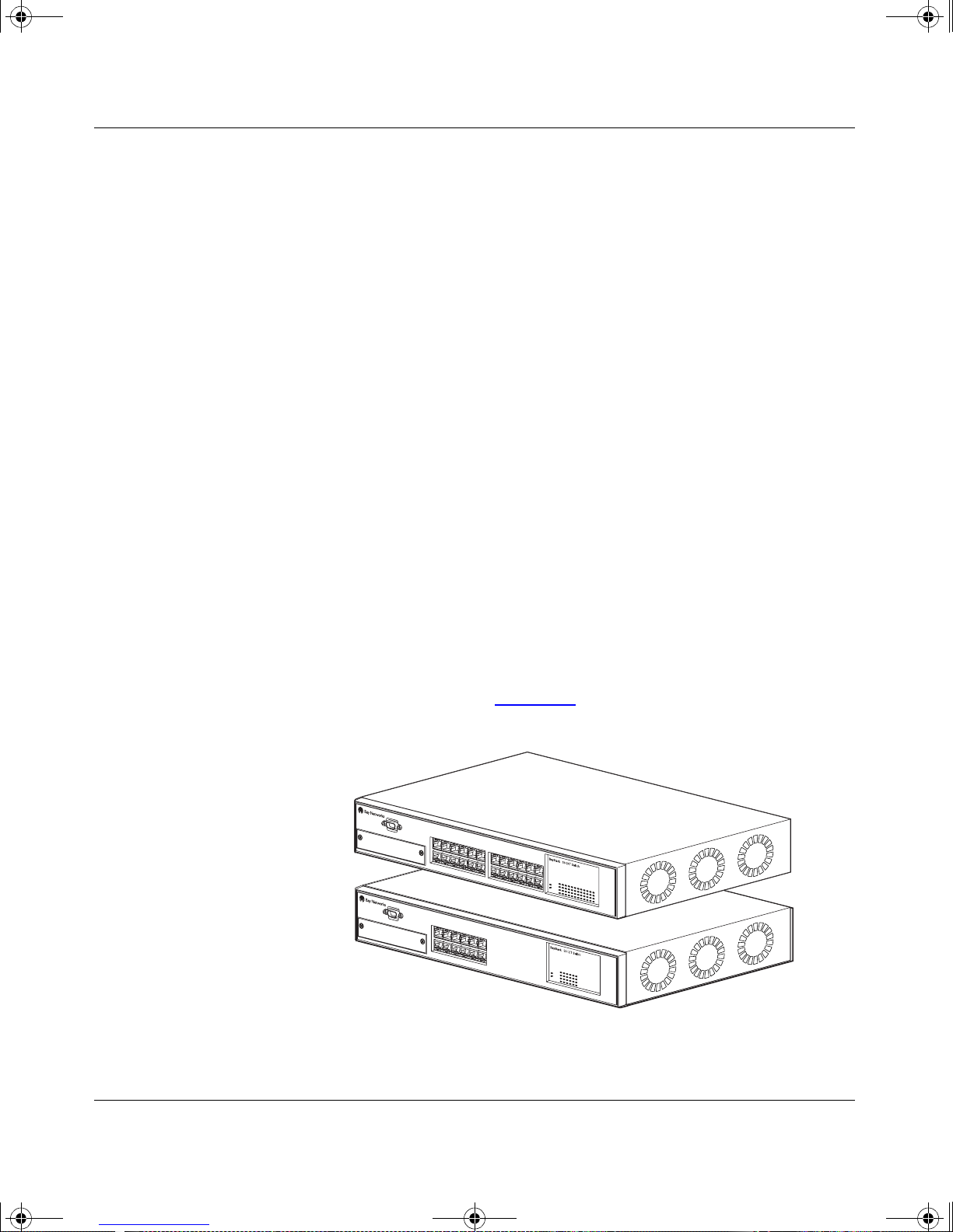
There are tw o versions of t he BayStack 350 swit ch: the BayStack 350 -24 T s wit ch
and the BayStack 350-12T switch (Figure 1-1
BayStack 350-24T
BayStack 350-12T
).
3
3
Figure 1-1. BayStack 350 10/100/1000 Series Switches
304376-B Re v 00
BS35001A
1-1
Page 26
kombk.book Page 2 Thursday, February 18, 1999 10:59 AM
Using the BayStack 350 10/100/1000 Series Switch
Front-Panel
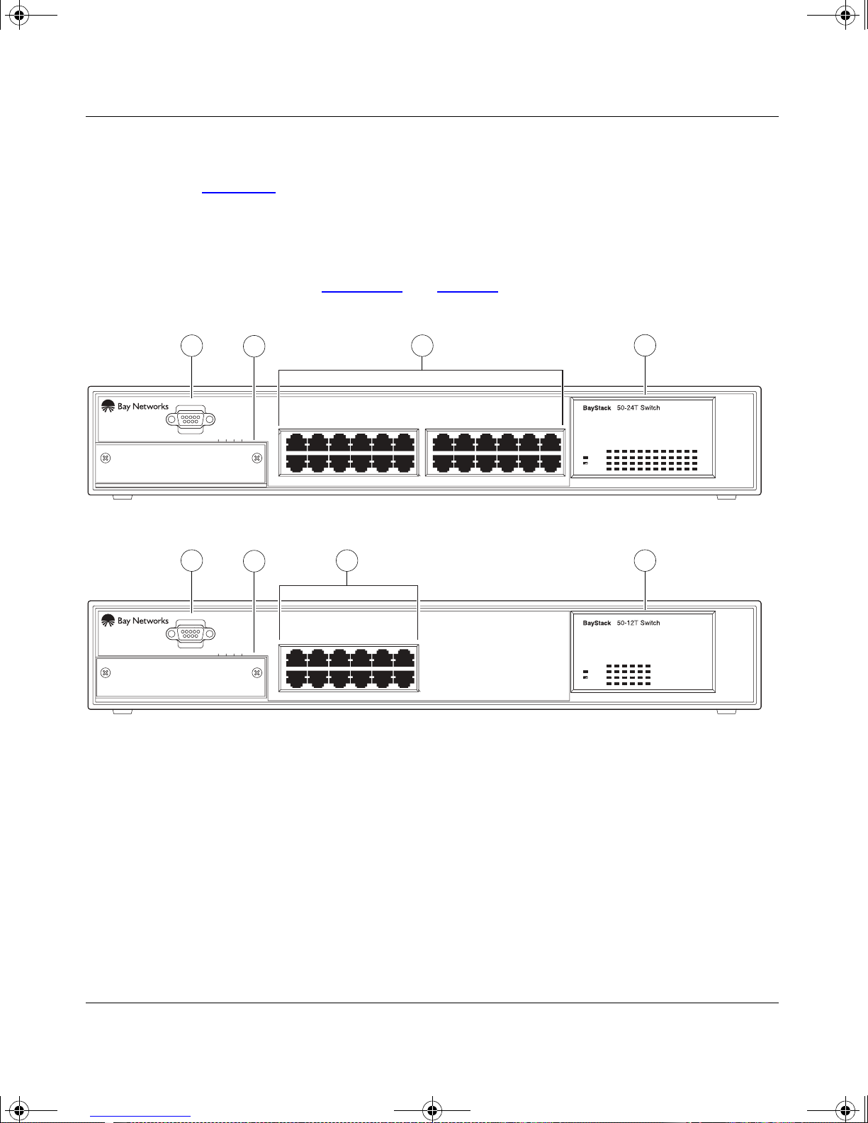
Figure 1-2 shows the front-panel of the Bay Stack 350-24T switch and the
BayStack 350-12T switch. Descriptions of the front-panel components follow the
figures.
For a description of the components located on the back-panel of the BayStack
350 switch, see “Back-Panel
” on page 1-6.
1
Comm Port
Uplink/Expansion Module
1
Comm Port
Uplink/Expansion Module
13 1514
2
5713 9
2826 2725
682 4 10 12
3
11
17 1913 15 21
18 2014 16 22 24
23
Pwr
Status
4
3
10/100
Activity
10/100
Activity
BayStack 350-24T
2
16
3 4
3
5713 9
682 4 10 12
11
Pwr
Status
10/100
Activity
10/100
Activity
BayStack 350-12T
1
= Comm Port
2
= Uplink/Expansion slot
3
= 10BASE-T/100BASE-TX port connectors
4
= LED display panel
Figure 1-2. Front-Panel Components
1-2
BS35002A
304376-B Rev 00
Page 27

kombk.book Page 3 Thursday, February 18, 1999 10:59 AM
Comm Port
The Comm Port (also referred to as the Console/Comm Port) allows you to access
the console interface (CI) screens and customize your network using the supplied
menus and screens (see Chapter 3, “Using the Console Interface”).
The Console/Comm Port is a DB-9, RS-2 32-D male serial port connector. Y ou can
use this connector to connect a management station or console/terminal to the
switch by using a straight-through DB-9 to DB-9 standard serial port cable (see
“Connecting the Console/Comm Port” on page 2-10).
BayStack 350 10/100/1000 Series Switches
Note:
The Console/Comm Port is configured as a data communications
equipment (DCE) connector. Ensure that your RS-232 cable pinouts are
configured for DCE connections (see “DB-9 (RS- 232- D) Console/Comm Port
Connector” on page D-5).
The console port runs at 9600 baud and uses eight data bits, one stop bit, and no
parity as the communications format, with flow control set to disabled.
Uplink/Expansion Slot
The Uplink/Expansion slot allows you to attach optional media dependent
adapters (MDAs) that support a range of media types (see Appendix B, “Media
Dependent Adapters” for more information about MDA types available from Bay
Networks).
10BASE-T/100BASE-TX Port Connectors
BayStack 350 switches use 10BASE-T/100BASE-TX RJ-45 (8 -pi n mod ula r) port
connectors.
Note:
The RJ-45 port connectors on BayStack 450 switches manufactured
prior to December 1998 are numbered 1 to 12 and 13 to 24, in succession fr om
left to right. Later units use port conn ectors t hat ar e conf igure d with o ne or tw o
dual, six-port groups, numbered 1 to 12 and 13 to 24. The top rows are odd
numbered and the bottom rows are even numbered (see Figure 1-2
page 1-2
). Port-specific examples in this guide show the appropriate port
connections when required; other examples apply to both versions.
304376-B Rev 00
on
1-3
Page 28
kombk.book Page 4 Thursday, February 18, 1999 10:59 AM
Using the BayStack 350 10/100/1000 Series Switch
All BayStack 350 switche s are shipped wit h port connector s configur ed as MDI-X
(media-dependen t interface- crossov er). These ports conne ct ove r straight cables to
the network interface contr oller (NIC) card in a node or server, similar to a
conventional Eth ern et repe at er hu b. If you a re c onnecting to another Ether net hub
or Ethernet switch, you need a crossover cable unless an MDI connection exists
on the associated port of the attached device (see “MDI and MDI-X Devices” on
page D-2).
The switches use auto sensing ports that are d esigned to operate at 10 Mb/s or at
100 Mb/s, depending on the connecting device. These ports support the IEEE
802.3u autonegotiation standard, which means that when a port is connected to
another device that also supports the IEEE 802.3u standard, the two devices
negotiate the best speed and duplex mode of operation.
The switch ports also support half- and full-duplex mode operation (see
“Connecting the 10BASE-T/100BASE-TX Ports” on page 2-9).
The switch uses 10BASE-T/100BASE-TX RJ-45 port connectors to connect to
10 Mb/s or 100 Mb/s Ethernet segments or nodes.
Note:
Use only Category 5 copper unshielded twisted pair (UTP) cable
connections when connecting 10BASE-T/100BASE-TX ports.
See Appendix D, “Connectors and Pin Assignments” for more information about
the RJ-45 port connectors.
LED Display Panel
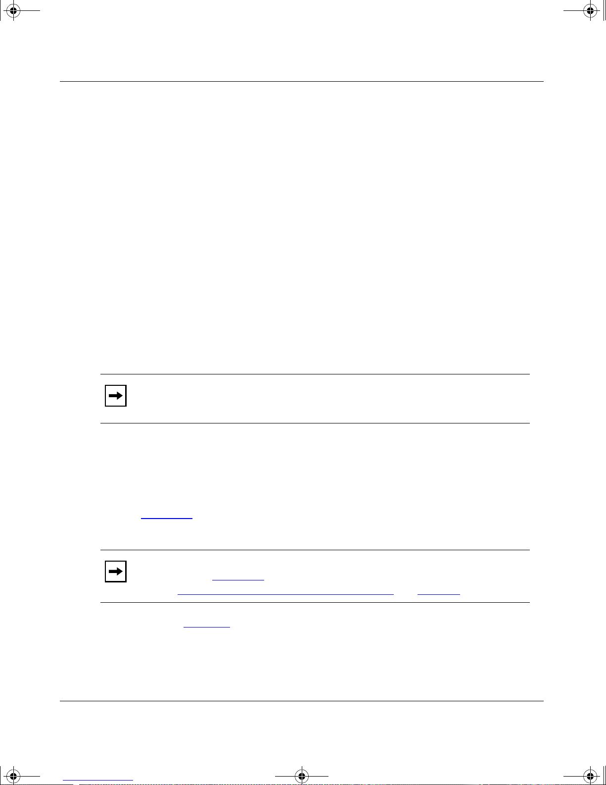
Figure 1-3
shows the LED display panels for the BayStack 350-24T and the
BayStack 350-12T models.
Note:
than shown in Figure 1-3
note in “
Refer to Table 1-1
The LED display panel configuration for your switch may be different
, depending on the date of manufacturing (see the
10BASE-T/100BASE-TX Port Connectors” on page 1-3).
for a description of the LEDs.
1-4
304376-B Rev 00
Page 29

kombk.book Page 5 Thursday, February 18, 1999 10:59 AM
BayStack 350 10/100/1000 Series Switches
BayStack
Pwr
Status
BayStack
Pwr
Status
350-24T Switch
153
2642220 241814 1612810
BayStack 350-24T
350-12T Switch
153 1179
26412810
10/100
Activity
10/100
Activity
1713 151179
2119 23
10/100
Activity
10/100
Activity
Figure 1-3. LED Display Panel
Table 1-1. LED Descriptions
Label Type Color State Meaning
Pwr Power status Green On DC power is available to the switch’s internal circuitry.
304376-B Rev 00
BayStack 350-12T
BS35003A
Off No AC power to switch or power supply failed.
(continued)
1-5
Page 30
kombk.book Page 6 Thursday, February 18, 1999 10:59 AM
Using the BayStack 350 10/100/1000 Series Switch
Table 1-1. LED Descriptions (continued)
Label Type Color State Meaning
Status System status Green On Self-test passed successfully and switch is operational.
Blinking A nonfatal error occurred during the self-test.
Off The switch faile d the self-test.
10/100 10/100 Mb/s
port speed
Green On The correspo ndi ng port is set to ope r ate at 1 00 M b/s an d
the link is good.
indicator
Green Blinking The corresponding port has been disabled by software.
Amber On The corresponding port is set to operate at 10 Mb/s and
the link is good.
Amber Blinking The corresponding port has been disabled by software.
Off The link connection is bad or there is no connection to
this port.
Activity Port activity Green Blinking Indicates network activity for the corresponding port. A
high level of network activity can cause the LEDs to
appear to be on continuously.
Back-Panel
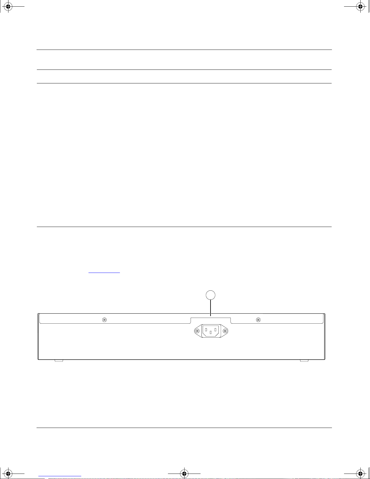
This section describes the BayStack 350 switch back-panel components
(Figure 1-4
). Descriptions of the back-panel components follow the figure.
1
1 = AC power receptacle
Figure 1-4. Back-Panel Components
1-6
100-240V
47-63Hz~
BS35004A
304376-B Rev 00
Page 31

228FA
kombk.book Page 7 Thursday, February 18, 1999 10:59 AM
AC Power Receptacle
The AC power receptacle accepts the AC power cord (supplied). For installation
outside of North Ameri ca, mak e sure that you ha ve t he proper p owe r cord for your
region. Any cord used must have a CEE-22 standard V female connector on one
end and must meet the IEC 320-030 specifications. Table 1-2
for international power cords.
Table 1-2. International Power Cord Specifications
Country/Plug description Specifications Typical plug
BayStack 350 10/100/1000 Series Switches
lists specifi cations
Continental Europe:
• CEE7 standard VII male plug
• Harmonized cord (HAR marking
on the outside of the cord jacket
to comply with the CENELEC
Harmonized Document HD-21)
U.S./Canada/Japan:
• NEMA5-15P male plug
• UL recognized (UL stamped
on cordjacket)
• CSA certified (CSA label
secured to the cord)
United Kingdom:
• BS1363 male plug with fuse
• Harmo nized cord
220 or 230 VAC
50 Hz
Single phase
100 or 120 VAC
50–60 Hz
Single phase
227FA
240 VAC
50 Hz
Single phase
229FA
Australia:
• AS3112-1981 Male plug
304376-B Rev 00
240 VAC
50 Hz
Single phase
230FA
1-7
Page 32

kombk.book Page 8 Thursday, February 18, 1999 10:59 AM
Using the BayStack 350 10/100/1000 Series Switch
Cooling Fans
The variable-speed cooling fans are located on one side of the BayStack 350
switch to provide cooling for the internal components. When you install the
switch, be sure to allow enough space on both sides of the switch for adequate air
flow.
Features
BayStack 350 switches provide wire-speed switching that allows
high-performance, low-cost connections to full-duplex and half-duplex
10/100/1000 Mb/s Ethernet local area networks (LANs).
BayStack 350 switches offer the following features:
• High-speed forwarding rate: up to 3 million packets per second (peak)
• Store-and-forwa rd switch: Full-performan ce forwarding at full line speed,
utilizing a 2.56 Gigabit/second switch fabric
• Learning rate: 3 million addresses per second (peak)
• Address Database Size: 16,000 entries at line rate (32,000 entries without
flooding)
• Spanning Tree Protocol (STP): complies with IEEE 802.1D standard. STP
can be disabled on the entire switch or on a per-port basis.
• IEEE 802.1Q Port-based virtual LANs (VLANs)
• IGMP Snooping
• IEEE 802.1p Prioritizing
• MultiLink Trunking, supporting:
- Switch-to-switch trunks
- Switch-to-server trunks
• Port Mirroring (Conversation Steering)
- Port-base d
- MAC address-based
• Console/Comm Port: Allo ws users to conf igure and manage the swit ch locally
or remotely.
1-8
304376-B Rev 00
Page 33

kombk.book Page 9 Thursday, February 18, 1999 10:59 AM
• SNMP agent support for the following Management Information Bases
(MIBs):
- Bridge MIB (RFC 1493)
- Ethernet MIB (RFC 1643)
- RMON MIB (RFC 1757)
- MIB-II (RFC 1213)
- Interface MIB (RFC 1573)
- Bay Networks proprietary MIBs:
s5Chass MIB
s5Agent MIB
BayStack 350 10/100/1000 Series Switches
s5ECM MIB (Ethernet Common)
s5emt MIB (multi-segment topology)
Rapid City MIB
• Rate limiting: Adjustable broadcast or IP Multicast pac ket-rate limits for
control of broadcast and IP Multicast storms
• TELNET:
- Support for up to four simultaneous TELNET sessions
- Optional password protection
- Login time-out
- Failed-login guard
- Inactivity time-out
- Allowed source addresses
- Event logging
• IEEE 802.3u-compliant autonegotiation ports, with four modes:
- 10BASE-T half-duplex
- 10BASE-T full-duplex
- 100BASE-TX half-duplex
- 100BASE-TX full-duplex
304376-B Rev 00
1-9
Page 34

kombk.book Page 10 Thursday, February 18, 1999 10:59 AM
Using the BayStack 350 10/100/1000 Series Switch
• Remote monitoring (RMON), with four groups integrated:
- Statistics
- History
- Alarms
- Events
• Front-panel light emitting diodes (LEDs) to monitor the following:
- Power status
- System status
- Per-port sta tus for the following:
1000 Mb/s link
100 Mb/s link
10 Mb/s link
Half- and full-duplex transmission
Tx/Rx activity
Management enable/disable
• Upgradeable device firmware in nonvolatile flash memory using the Trivial
File Transfer Protocol (TFTP)
IEEE 802.1Q VLANs
BayStack 350 switches support up to 64 port-based VLANs with IEEE 802.1Q
tagging available per port. When a switch port is configured to be a member of a
VLAN, it is added to a group of ports (workgroup) that belong to one broadcast
domain. You can ass ign d ifferent p orts (and ther ef ore the d evices att ached to the se
ports) to different broadcast domains. This feature allows network flexibility
because you can reassign VLANs to accommodat e network mov es, additions , and
changes, eliminating the need to change physical cabling.
For more information about 802.1Q VLANs, see “
Workgroups” on page 1-18.
1-10
IEEE 802.1Q VLAN
304376-B Rev 00
Page 35

kombk.book Page 11 Thursday, February 18, 1999 10:59 AM
IGMP Snooping Feature
For conserving bandwidth and controlling IP Multicast, the IGMP Snooping
feature can provide the same benefit as IP Multicast routers, but in the local area.
BayStack 350 10/100/1000 Series Switches
For more information about the IGMP Snooping feature, see “
on page 1-34
.
IEEE 802.1p Prioritizing
BayStack 350 swit ches can pr ioriti ze the order in whi ch pack ets are forw arded, on
a per-port basis.
For more information about the 802.1p prioritizing feature, see “
Prioritizing” on page 1-39.
MultiLink Trunking
The MultiLink Trunking fea ture allows a use r to group multiple p ort s (up to four)
together when forming a link to another switch or server, thus increasing
aggregate thr oughput of the interconnection between two devic es , up to 800 Mb/s
in full-duplex mode. BayStack 350 switches can be configured with up to six
MultiLink Trunks.
For more information about the MultiLink Trunking feature, see “MultiLink
Trunks” on page 1-43.
IGMP Snooping”
IEEE 802.1p
Port Mirroring
The Port Mirroring feature (sometim es referred to as conversation steering)
allows a user to designate a single switch port as a traffic monitor for up to two
specified ports or two media access control (MAC) addresses. You can specify
Port-Based monitoring, where all traffic on specified ports is monitored, or
Address-Based monitoring, where traffic between specified MAC addresses is
monitored. You can attach a probe de vi ce (s uch as a Ba y Netw orks StackPr obe, or
equivalent) to the designated monitor port.
For more information about the port mirroring feature, see “Port Mirroring
(Conversation Steering)” on page 1-61.
304376-B Rev 00
1-11
Page 36

kombk.book Page 12 Thursday, February 18, 1999 10:59 AM
Using the BayStack 350 10/100/1000 Series Switch
Flash Memory Storage
The BayStack 350 switch uses flash memory to store the switch software image.
Flash memory allows you to upda te the software image with a newer vers ion
without changing the switch hardware.
An in-band connection between the switch and the TFTP load host is required to
download the software image (see “Software Download” on page 3-70).
For information about connecting a console terminal for this procedure, see
“Connecting the Console/Comm Port” on page 2-10.
Note:
If a BootP server is set up properly on the network and the BayStack
350 switch detects a corrupted software image during the self-test, the switch
automatically uses TFTP to download a new software image.
Certain configuration parameters, including the system characteristics strings,
some VLAN pa rameters, the IGMP configuration pa rameters, and th e MultiLink
trunk names are stored in flash memory. These parameters are updated every 10
minutes or whenever a Reset command is executed. Powering off the switch
within 10 minutes of changing these configuration parameters can cause the
configuration parameters to be lost.
BootP Automatic IP Configuration
The BayStack 350 switc h has a unique 48-bit har dware address, or MAC address,
that is printed on a label on the back panel. You use this MAC address when you
configure the network BootP server to recognize the BayStack 350 switch BootP
requests. A properly configured BootP server enables the switch to automatically
learn its assigned I P address, su bnet mask, IP ad dress o f the defau lt route r (def ault
gateway), and software image file name.
For an example of a BootP configuration file, see Appendix F, “Sample BootP
Configurat ion Fil e.”
1-12
304376-B Rev 00
Page 37

kombk.book Page 13 Thursday, February 18, 1999 10:59 AM
SNMP MIB Support
The BayStack 350 switch supports an SNMP agent with industry standard MIBs,
as well as private MIB extensions, which ensures compatibility with existing
network management tools. The BayStack 350 switch supports MIB-II
(RFC 1213) and the RMON MIB (RFC 1757), which provide access to detailed
management statistics. With SNMP management, you can configure SNMP traps
(on individual ports) to be generated automatically for conditions such as an
unauthorized access attempt or changes in a port’s operating status.
Autosensing and Autonegotiation
BayStack 350 switches are autosensing and autonegotiating devices:
BayStack 350 10/100/1000 Series Switches
• The term autosense refers to a port’s ability to sense the speed of an attached
device.
• The term autoneg oti at io n refers to a standa rdize d p rotoco l (IEEE 802 .3u) that
exists between two IEEE 802.3u-capable devices. Autonegotiation allows the
BayStack 350 switch to select the best of both speed and duplex modes.
Autosensing is used when the attached devic e i s not capable of autonegotiat i on or
is using a form of autonegotiation that is not compatible with the IEEE 802.3u
autonegotiation standard. In this case, because it is not possible to sense the
duplex mode of the attached device, the BayStack 350 switch reverts to
half-duplex mode.
When autonegotiation-capable devices are attached to the BayStack 350 switch,
the switch ports ne gotiate do wn from 100 Mb/s spe ed and full-dupl ex mode unti l a
supported speed and duplex mode is acknowledged by the attached device.
For more information about autosensing and autonegotiation modes, see
“Autonegotiation Modes” on page 4-6.
304376-B Rev 00
1-13
Page 38

kombk.book Page 14 Thursday, February 18, 1999 10:59 AM
Using the BayStack 350 10/100/1000 Series Switch
Configuration and Switch Management
The BayStack 350 switch is shipped directly from the factory ready to operate in
any 10BASE-T or 100BASE-TX standard network. You can manage the switch
using any generic SNMP-based network management software; however, you
must assign an IP address to the switch. You can set the switch’s IP address by
using the Console/Comm Port or BootP, which resides on the switch.
For more information about using the Console/Comm Port to configure the
switch, see Chapter 3, “Using the Console Interface.”
Network Configuration
You can use BayStack 350 switches to connect workstations, personal computers
(PCs), and ser vers to ea ch other by c onnecti ng these de vices d irectly to t he switch ,
through a share d media hub t hat is conn ected to t he swit ch, or b y creat ing a virt ual
LAN (VLAN) through the switch.
This section provides three network configuration examples using BayStack 350
10/100/1000 Series Switches:
• Desktop switch application
• Segment switch application
• High-density switched workgroup application
Note:
All models of the BayStack 350 10/100/1000 Series Switches can be
used interchangeably in the following network configuration examples.
1-14
304376-B Rev 00
Page 39
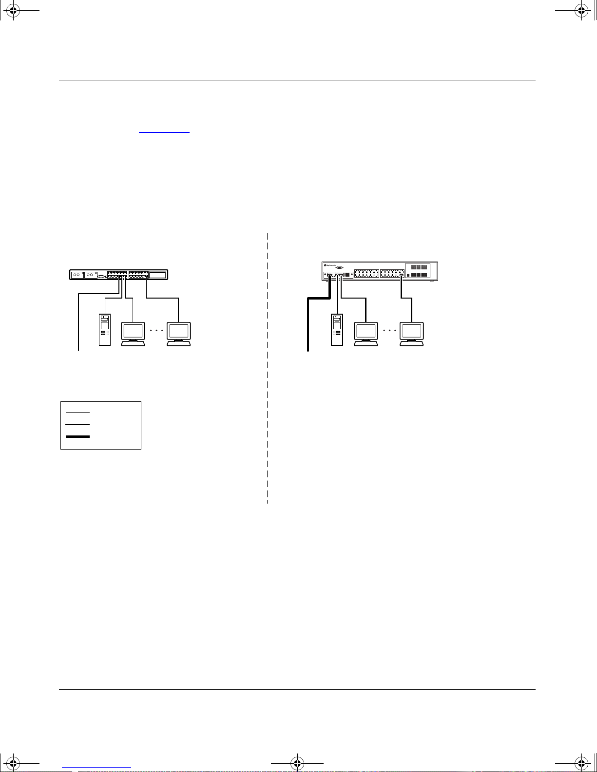
kombk.book Page 15 Thursday, February 18, 1999 10:59 AM
Desktop Switch Application
Figure 1-5 shows the BayStack 350-24T switch used as a desktop switch, where
desktop workstations are connected directly to switch ports.
This configuration provides dedicated 100 Mb/s connections to the network
center, to the server, and up to 26 users. This configuration uses the optional
400-4TX MDA (10BASE-T/100BASE-TX MDA).
Before After
BayStack 350 10/100/1000 Series Switches
10BASE-T hub
Server Up to 22 users
To
Network
Center
Key
10 Mb/s
100 Mb/s
200 Mb/s
- 22 users share 10 Mb/s (10/22 Mb/s per user)
- Server bottleneck (10 Mb/s bandwidth)
- Network center bottleneck (10 Mb/s bandwidth)
BayStack 350-24T switch
Server Up to 26 users
To
Network
Center
- 26 users; each with dedicated 100 Mb/s bandwidth
- Server with dedicated 100 Mb/s bandwidth
- Network center with dedicated 100 Mb/s full-duplex
bandwith (200 mb/s bidirectional)
BS35005A
Figure 1-5. BayStack 350-24T Used as a Desktop Switch
304376-B Rev 00
1-15
Page 40
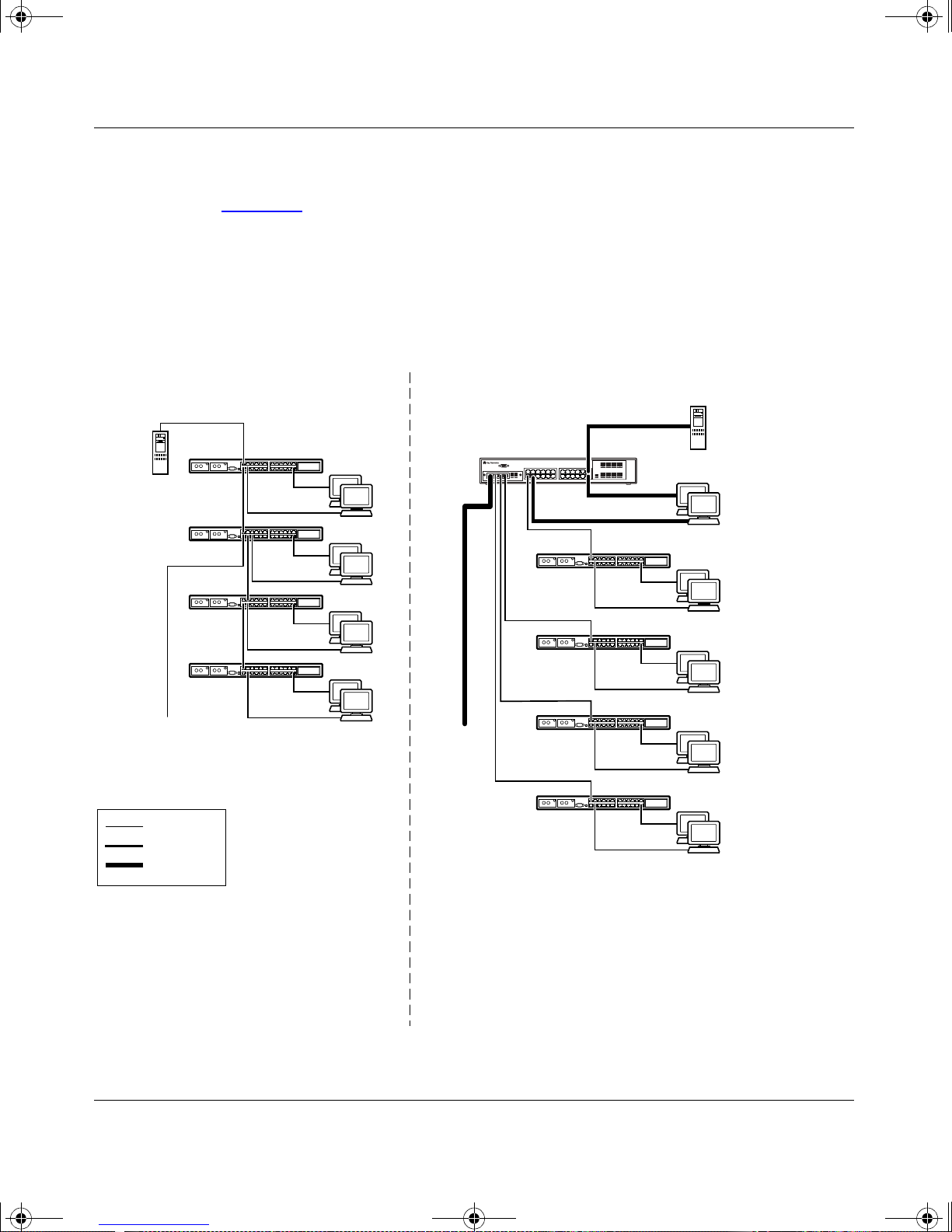
kombk.book Page 16 Thursday, February 18, 1999 10:59 AM
Using the BayStack 350 10/100/1000 Series Switch
Segment Switch Application
Figure 1-6 shows the BayStack 350-24T switch used as a segment switch to
alleviate user contention for bandwidth and eliminate server and network
bottlenecks. Befo re segmenta ti on, 88 users had a to tal bandwidth of o n ly 10 Mb/s
available. After segmentation, 92 users have 40 Mb/s, four times the previous
bandwidth, while adding 22 dedicated 100 Mb/s connections. This configuration
can be extended to add more segments without degrading performance.
Key
Server
To
Network
Center
Before
10BASE-T hubs
Up to
88 users
BayStack 350-24T
switch
To
Network
Center
After
Server
Up to 22
users
Up to 23
users
Up to 23
users
Up to 23
users
Up to 23
users
10 Mb/s
100 Mb/s
200 Mb/s
- 88 users share 10 Mb/s (10/88 Mb/s per user)
- Server bottleneck (10 Mb/s bandwidth)
- Network center bottleneck (10 Mb/s bandwidth)
-Total of 88 users
Figure 1-6. BayStack 350-24T Used as a Segment Switch
1-16
- Four sets of 23 users; each set shares 10 Mb/s
(10/23 Mb/s per user)
- Addition of 22 users; each with dedicated
100 Mb/s bandwidth
- Server with dedicated 100 Mb/s bandwidth
- Network center with dedicated 100 Mb/s full-duplex bandwidth
(200 Mb/s bidirectional)
- Total of 114 users
BS35006A
304376-B Rev 00
Page 41
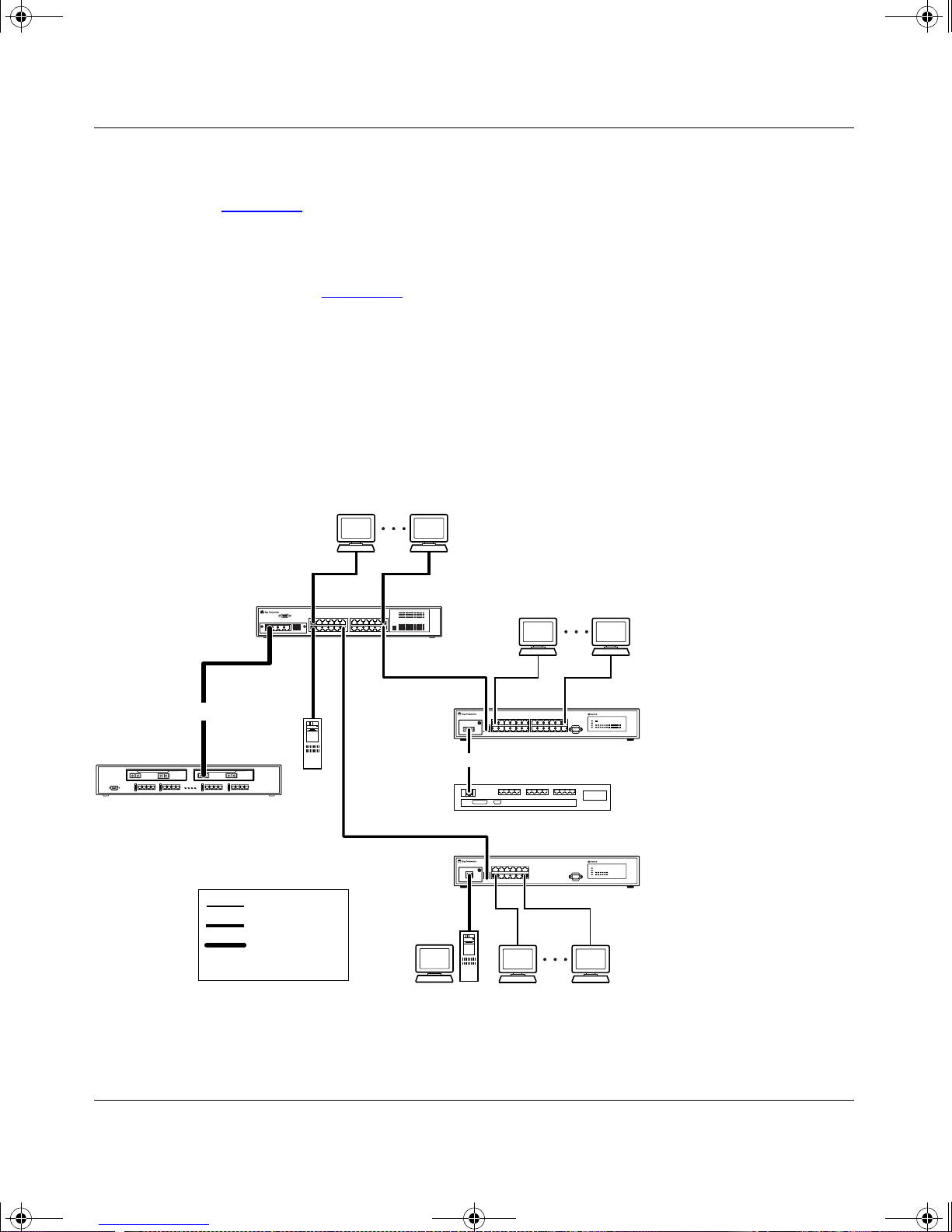
kombk.book Page 17 Thursday, February 18, 1999 10:59 AM
High-Density Switched Workgroup Application
Figure 1-7 shows a BayStack 350-24T switch with a high-speed (gigabit)
connection to a Bay Networks Accelar
switches are also shown in this example of a high-density switched workgroup.
BayStack 350 10/100/1000 Series Switches
™
1100 switch. BayStack 303 and 304
As shown in Figure 1-7
connecting to the BayStack 350 switch with an optional gigabit (1000BASE-SX)
MDA for maximum bandwidth. The BayStack 303 and 304 switches have 100
Mb/s connections to the BayStack 350 switch, a 100BASE-TX hub, and a 100
Mb/s server and 10 Mb/s connections to DTE (data terminal equipment).
See the Bay Networks library Web page: support.baynetworks.com/library/ for
online documentation about the Bay Networks Accelar 1100 switch and the
BayStack 303 and 304 switches.
BayStack 350-24T
switch
F
, the Accelar 1100 switch is used as a backbone switch,
303
BayStack 303
switch
F
CPUPS1 PS2FAN
Accelar 1100 switch
Key
Server
10 Mb/s
100 Mb/s
1000 Mb/s
(Gigabit)
100BASE-TX
hub
304
BayStack 304
switch
Figure 1-7. Configuring Power Workgroups and a Shared Media Hub
304376-B Rev 00
BS35007A
1-17
Page 42
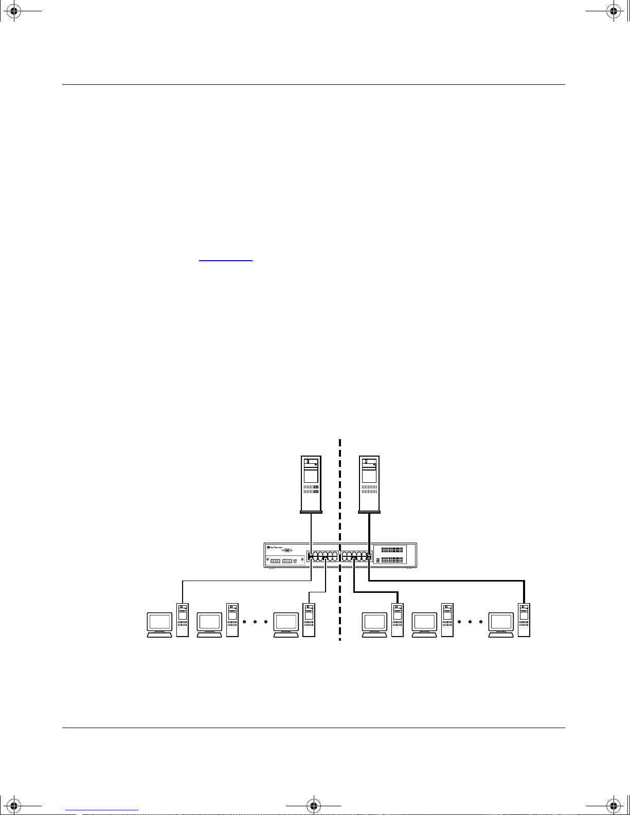
kombk.book Page 18 Thursday, February 18, 1999 10:59 AM
Using the BayStack 350 10/100/1000 Series Switch
IEEE 802.1Q VLAN Workgroups
BayStack 350 switches support up to 64 port-based VLANs with 802.1Q tagging
available per port. Ports are group ed int o broadcast domains by assigning them to
the same VLAN. Frames received in one VLAN can only be forwarded within
that VLAN, and IP Multicast frames and unknown unicast frames are flooded
only to ports in the same VLAN.
Setting up virtual LANs (VLANs) is a way to segment networks to increase
network capacity and performance without changing the physical network
topology (Figure 1-8
segment tha t i s a single broadcast domai n. Wh en a switch port is configured to be
a member of a VLAN, it is added to a group of ports (workgroup) that belong to
one broadcast domain.
). Wit h netw ork se gment atio n, each swi tch por t connec ts to a
BayStack 350 switches allow you to assign ports to VLANs using the console or
TELNET; VLAN assignment is not currently available through SNMP. You can
assign different ports (and therefore the devices attached to these ports) to
different broadcast domains. This feature allows network flexibility because you
can reassign VLANs to accommodate network moves, additions, and changes,
eliminating the need to change physical cabling.
VLAN 1 VLAN 2
BayStack 350-24T
switch
Figure 1-8. Port-Based VLAN Example
1-18
BS35009A
304376-B Rev 00
Page 43

kombk.book Page 19 Thursday, February 18, 1999 10:59 AM
IEEE 802.1Q Tagging
BayStack 350 switches operate in accordance with the IEEE 802.1Q tagging
rules. Important terms used with the 802.1Q tagging feature are:
• VLAN Identifier (VID) --- the 12-bit portion of the VLAN tag in the frame
header tha t identifies an explicit VLAN.
• Port VLAN Identifier (PVID) --- a cl assificatio n mechanis m that ass ociat es a
port with a specific VLAN. For example, a port with a PVID of 3 (PVID =3)
assigns all untagged frames received on this port to VLAN 3.
• Tagged frame --- the 32-bit field (VLAN tag) in the frame header that
identifies the frame as belonging to a specific VLAN. Untagged frames are
marked (tagged) wi th this class if ication as t hey lea v e the switch thr ough a port
that is configured as a tagged port.
BayStack 350 10/100/1000 Series Switches
• Untagged frame --- a frame that does not carry any VLAN tagging
information in the frame header.
• VLAN port members --- a set of ports that form a broadcast domain for a
specific VLAN. A port can be a member of one or more VLANs.
• Untagged member --- a port that has been configured as an untagged member
of a specific VLAN. When an untagged frame exits the switch through an
untagged member port, the frame header remains unchanged. When a tagged
frame exits the switch through an untagged member port, the tag is stripped
and the tagged frame is changed to an untagged frame.
• Tagged member --- a port that has been configured as a member of a specific
VLAN. When an untagged frame exits the switch through a tagged member
port, the frame heade r is modif i ed t o incl ude t he 32- bit tag a ssoci ated with t he
PVID. When a tagged frame exits the switch through a tagged member port,
the frame header remains unchanged (original VID remains).
• User_priority --- a three-bit field in the header of a tagged frame. The field is
interpreted as a binary number, therefore has a value of 0 to 7. This field
allows the tagged fram e t o ca rry the user - priority across bri dged LANs where
the individual LAN segments may be unable to signal priority information.
• Por t priority --- the priority level assi gned to untagged frames received on a
port. This value becomes the us er_priority for the frame. Tagged packets get
their user_priority from the value contained in the 802.1Q frame header.
• Unregistered packet --- a tagged frame that contains a VID where the
receiving port is not a member of that VLAN.
304376-B Rev 00
1-19
Page 44
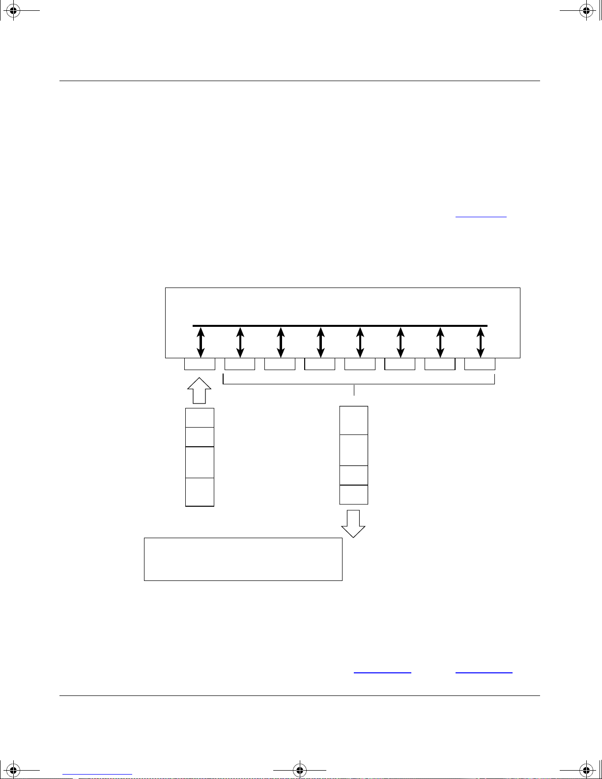
kombk.book Page 20 Thursday, February 18, 1999 10:59 AM
Using the BayStack 350 10/100/1000 Series Switch
• Filtering Database Identifier (FID) --- the specific filtering/forwarding
database within the BaySta ck 35 0 sw it ch t hat is a ssi gned to each VLAN. The
current version of software assigns all VLANs to the same FID. This is
referred to as Shared VLAN Learning in the IEEE 802.1Q specification.
The default configuration settings for BayStack 350 switches have all ports set as
untagged members of VLAN 1 with all ports configured as PVID = 1. Every
VLAN is assigned a unique VLAN identifier (VID) which distinguishes it from
all other VLANs. In the default configuration example shown in Figure 1-9
incoming packets are assigned to VLAN 1 by the default port VLAN identifier
(PVID =1) . Untagged p ackets enter and leave the switch unchange d.
802.1Q switch
, all
Port 1
PVID = 1
DA
SA
Incoming
untagged
packet
Key
By default:
Data
CRC
All ports are assigned PVID = 1
All ports are untagged members of VLAN 1
Port 2 Port 3 Port 4 Port 5
untagged packet
Outgoing
(unchanged)
VLAN 1
Port 6 Port 7 Port 8
CRC
Data
SA
DA
BS35010A
Figure 1-9. Default VLAN Settings
To configure VLANs, a user can reconfigure the switch ports as tagged or
untagged members of specific VLANs (see Figure 1-10
1-20
through Figure 1- 13 ).
304376-B Rev 00
Page 45
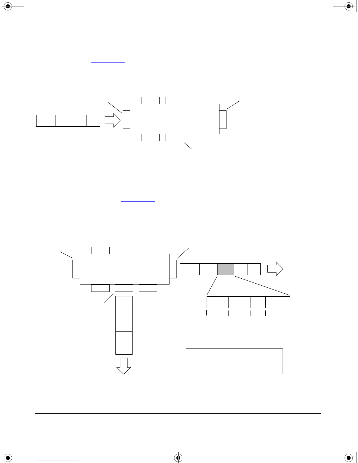
kombk.book Page 21 Thursday, February 18, 1999 10:59 AM
In Figure 1-10, untagged incoming packets are assigned directly to VLAN 2
(PVID = 2). Port 5 is configured as a tagged member of VLAN 2, and port 7 is
configured as an untagged member of VLAN 2.
BayStack 350 10/100/1000 Series Switches
PVID = 2
Untagged packet
DASADataCRC
Before
Port 1
Port 4
Port 6
Figure 1-10. 802.1Q Tagging (1 of 4)
As shown in Figure 1-11, the untagged packet is marked (tagged) as it leaves the
switch through port 5, which is configured as a tagged member of VLAN 2. The
untagged packet remains unchanged as it leaves the switch through port 7, which
is configured as an untagged member of VLAN 2.
PVID = 2
Port 1
Port 4
Port 2 Port 3
802.1Q Switch
Port 2 Port 3
802.1Q Switch
Port 7 Port 8
Port 5
Tagged member
of VLAN 2
Port 5
Untagged member
of VLAN 2
BS35011A
Tagged member
of VLAN 2
DASADataCRC* Tag
Port 6 Port 7 Port 8
Untagged memeber
of VLAN 2
Outgoing
untagged packet
(unchanged)
CRC
Data
SA
DA
Figure 1-11. 802.1Q Tagging (2 of 4)
304376-B Rev 00
(*Recalculated)
Key
Priority
CFI
VID
8100 CFI
16 bits 3 bits 1 bits 12 bits
After
- User_priority
- Canonical format indicator
- VLAN identifier
VID = 2Priority
BS35012A
1-21
Page 46
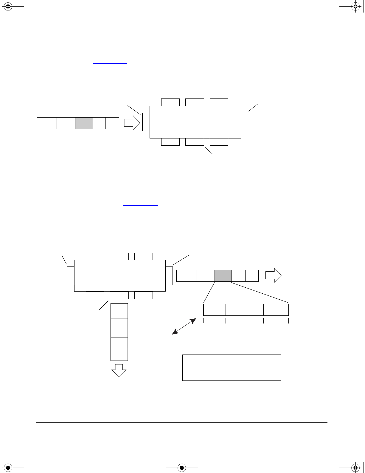
kombk.book Page 22 Thursday, February 18, 1999 10:59 AM
Using the BayStack 350 10/100/1000 Series Switch
In Figure 1-12, t agged inco ming pack ets are as signed di rectly to VLAN 2 bec ause
of the tag assignment in the packet. Port 5 is configured as a tagged member of
VLAN 2, and port 7 is configured as an untagged member of VLAN 2.
PVID = 2
Tagged packet
DASATagDataCRC
Before
Port 4
Figure 1-12. 802.1Q Tagging (3 of 4)
As shown in Figure 1-13, the tagged packet remains unchanged as it leaves the
switch through port 5, which is configured as a tagged member of VLAN 2.
However, the tagged packet is stripped (untagged) as it leaves the switch through
port 7, which is configured as an untagged member of VLAN 2.
PVID = 2
Port 1
Port 2 Port 3
Port 1
Port 6
Port 2 Port 3
802.1Q Switch
Port 7 Port 8
Tagged member
of VLAN 2
Tagged member
of VLAN 2
Port 5
Untagged member
of VLAN 2
BS35013A
Port 4
Untagged member
of VLAN 2
802.1Q Switch
Port 6 Port 7 Port 8
SA
DA
(*Recalculated)
Outgoing
untagged packet
changed
(tag removed)
CRC*
Data
Figure 1-13. 802.1Q Tagging (4 of 4)
1-22
Port 5
8100 CFI
16 bits 3 bits 1 bit 12 bits
Key
Priority
CFI
VID
- User_priority
- Canonical format indicator
- VLAN identifier
DASADataCRC Tag
VID = 2Priority
After
BS35014A
304376-B Rev 00
Page 47
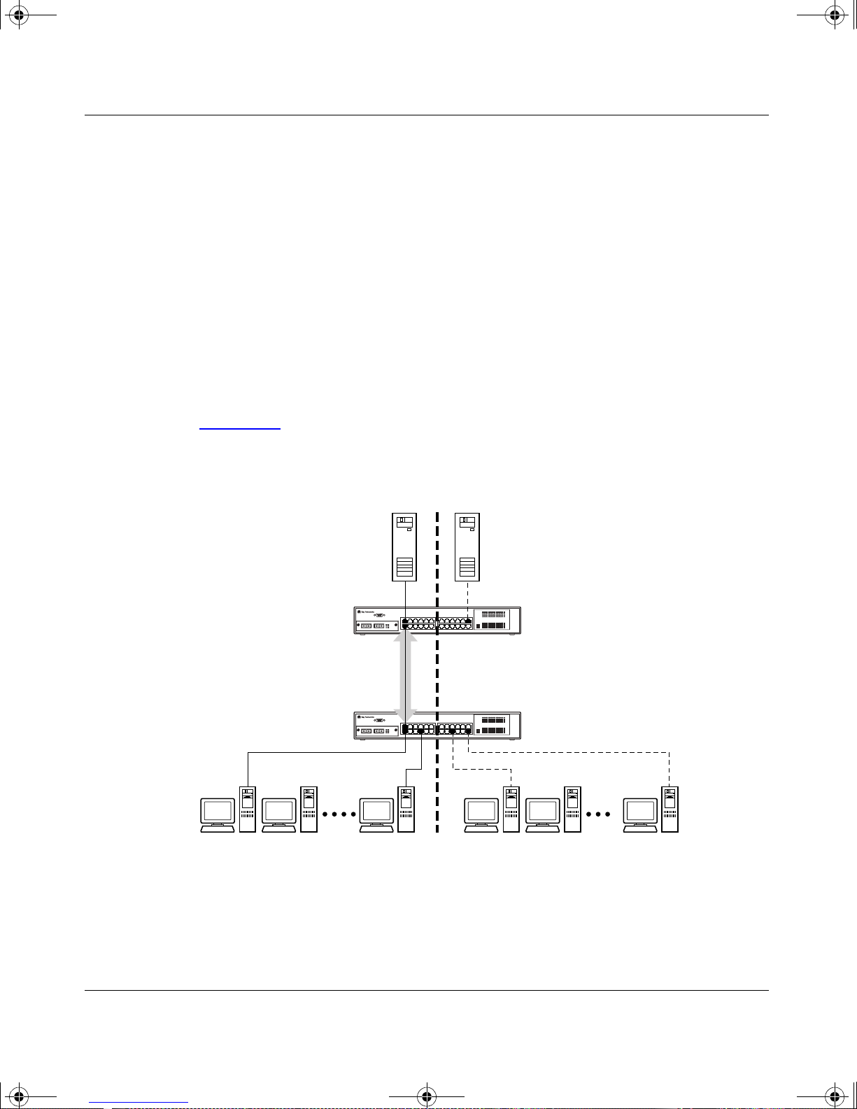
kombk.book Page 23 Thursday, February 18, 1999 10:59 AM
VLANs Spanning Multiple Switches
You can use VLANs to segment a network within a switch. When connecting
multiple switches, it is possible to connect users of one VLAN with users of that
same VLAN in another switch. However, the configuration guidelines depend on
whether both switches support 802.1Q tagging.
Wit h 802.1Q tagging enabl ed on a port for a VLAN, all frame s leavi ng the port for
that VLAN are marked as belonging to that specific VLAN. Users can assign
specific switch ports as members of one or more VLANs that span multiple
switches, without interfering with the spanning tree protocol.
VLANS Spanning Multiple 802.1Q Tagged Switches
BayStack 350 10/100/1000 Series Switches
Figure 1-14
shows VLANs spanni ng two BayStack 350 switche s. 802.1Q taggi ng
is enabled on S1, port 2 and on S2, port 1 for VLAN 1 and VLAN 2. Both ports
are tagged members of VLAN 1 and VLAN 2.
VLAN 1
S1
Both ports are tagged
members of VLAN 1
and VLAN 2
S2
VLAN 2
BayStack 350-24T
BayStack 350-24T
Figure 1-14. VLANs Spanning Multiple 802.1Q Tagged Switches
304376-B Rev 00
B35015A
1-23
Page 48
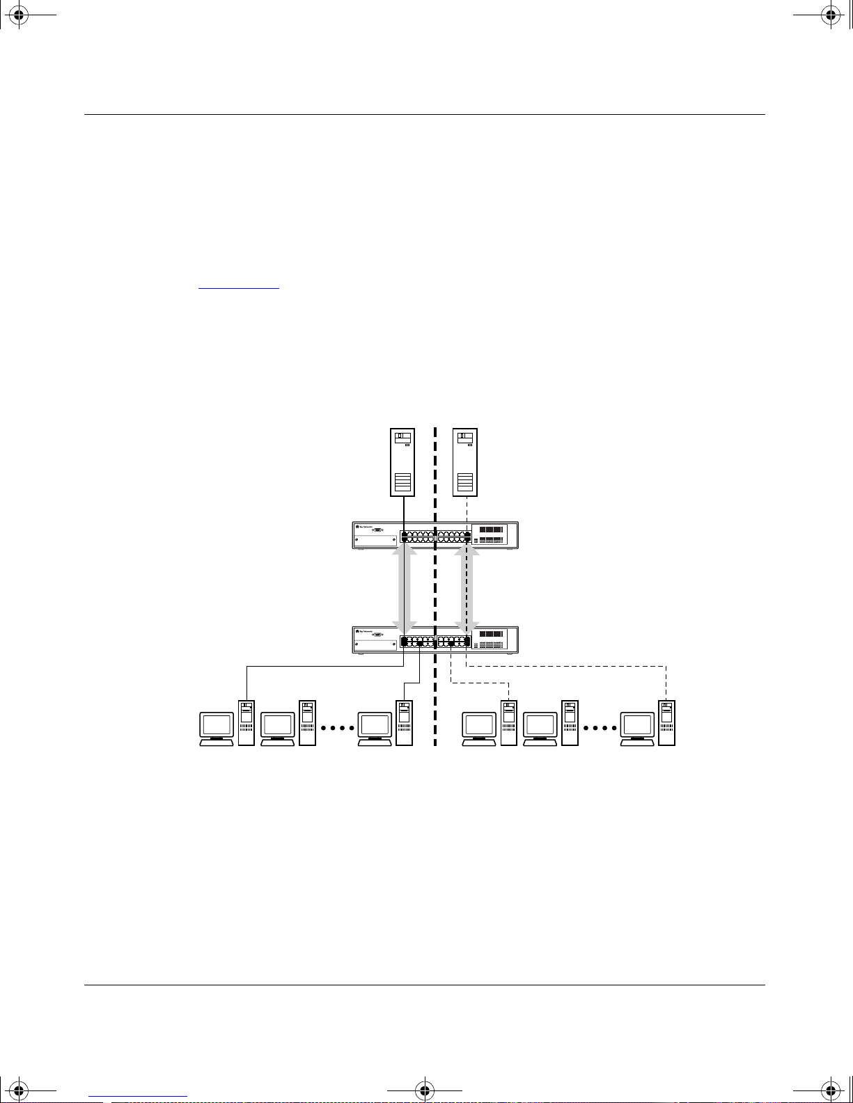
kombk.book Page 24 Thursday, February 18, 1999 10:59 AM
Using the BayStack 350 10/100/1000 Series Switch
Because there is only one link between the two switches, the Spanning Tree
Protocol (STP) treat s t his configuration as any ot her swi tc h-t o- swit ch connection.
For this configuration to work properly, both switches must support the 802.1Q
tagging protocol.
VLANS Spanning Multiple Untagged Switches
Figure 1-15
shows VLANs spanning multiple untagged switches. In this
configurat io n swi tch S2 does not support 802.1Q tagging a nd a si ngl e swi tc h por t
on each switch must be used for each VLAN.
For this configuration to work properly, spanning tree participation must be set to
Disabled because the STP is not supported across multiple LANs.
VLAN 1
S1
S2
VLAN 2
BayStack 350-24T
Untagged portsUntagged ports
Non-802.1Q
tagging switch
Figure 1-15. VLANs Spanning Multiple Untagged Switches
When the STP is enabled on these switches, only one link between each pair of
switches will be fo rwarding traffic. Beca use each port belongs to onl y one VLAN
at a time, connectivity on the other VLAN will be lost. Exercise care when
configuring the switches to ensure that the VLAN configuration does not conflict
with spanning tree configuration.
1-24
BS35016A
304376-B Rev 00
Page 49
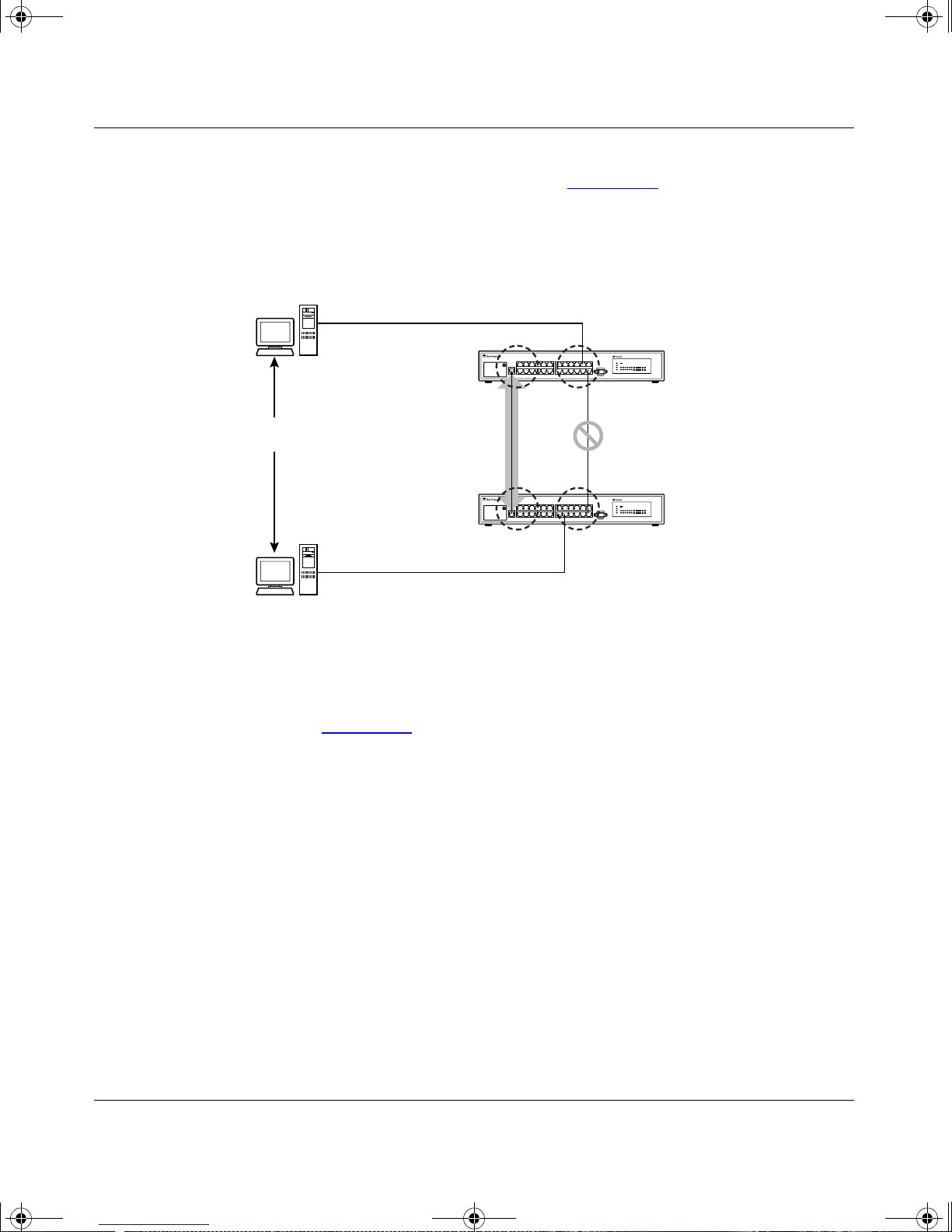
kombk.book Page 25 Thursday, February 18, 1999 10:59 AM
To connect multiple VLANs across switches with redundant links, the STP must
be disabled on all participating switch ports. Figure 1-16
consequences of enabling the STP when using VLANs between untagged
(non-802.1Q tagged) switches.
Station A
BayStack 350 10/100/1000 Series Switches
shows possible
BayStack 303 switch
303303
S1
VLAN 1 VLAN 2
No
Communications
Station B
Forwarding
VLAN 1 VLAN 2
Blocking
BayStack 303 switch
303
S2
BS35017A
Figure 1-16. Possible Problems with VLANs and Spanning Tree Protocol
As shown in Figure 1-16, with STP enabled, only one connection between swit ch
S1 and S2 is forwarding at any time. Communications failure occurs between
VLAN 2 of S1 and VLAN 2 of S2, blocking c ommunic at ions between Stations A
and B.
The link connecting VLAN 1 on swit ches S1 and S2 is selected a s th e forwarding
link based on port speed, duplex-mode, and port priority. Because the other link
connecting VLAN 2 is placed in to Bl ocki ng mode, stations on VLAN 2 in switch
S1 cannot communicate with stations in VLAN 2 on switch S2. With multiple
links only one link will be forwarding.
304376-B Rev 00
1-25
Page 50
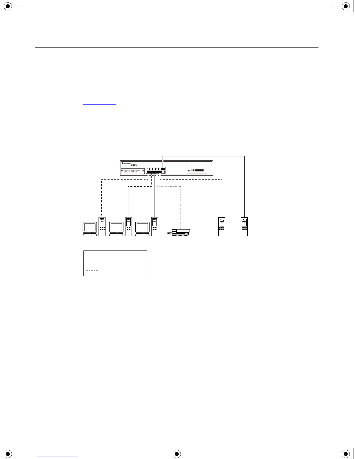
kombk.book Page 26 Thursday, February 18, 1999 10:59 AM
Using the BayStack 350 10/100/1000 Series Switch
Shared Servers
BayStack 350 switches allow ports to exist in multiple VLANs for shared
resources, such as servers, printers, and switch-to-switch connections. It is also
possible to have resources exist in multiple VLANs on one switch as shown in
Figure 1-17
In this example, clients on different broadcast domains share resources. The
broadcasts from ports configured in VLAN 3 can be seen by all VLAN port
members of VLAN 3.
BayStack 350-12T switch
.
S1
V2 V2 V1
Key
VLAN 1 (PVID=1)
VLAN 2 (PVID=2)
VLAN 3 (PVID=3)
V3
V1V2
BS35018A
Figure 1-17. Multiple VLANs Sharing Resources
In order for the above configuration to operate as described, the ports have to be
set to participate as VLAN port members. When this is done, the switch
establishes the appropriate bro adcast domains within the switch (see Figure 1 -18
).
1-26
304376-B Rev 00
Page 51
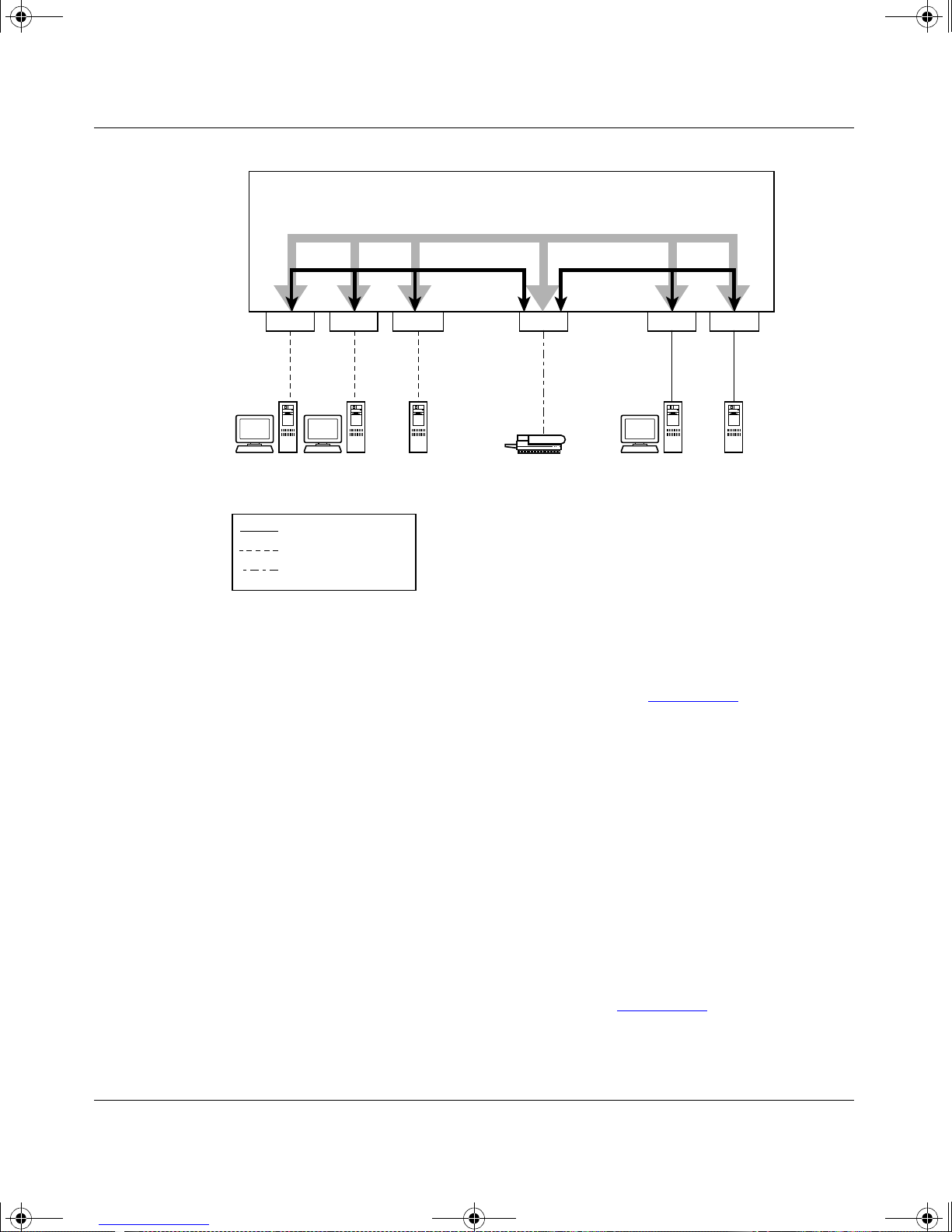
kombk.book Page 27 Thursday, February 18, 1999 10:59 AM
S1
BayStack 350 10/100/1000 Series Switches
VLAN 3
VLAN 2 VLAN 1
Port 2
PVID = 2 PVID = 3
V2 V2 V2 V1 V2
Key
VLAN 1 (PVID = 1)
VLAN 2 (PVID = 2)
VLAN 3 (PVID = 3)
Port 4 Port 10 Port 8
V3
Port 11Port 6
PVID = 1
BS35019A
Figure 1-18. VLAN Broadcast Domains Within the Switch
The broadcast domai n for eac h of the VLANs sho wn in Figure 1-18 are created b y
configuring VLAN port memberships for each VLAN and then configuring each
of the ports with the appropriate PVID/VLAN association:
• Ports 8, 6, and 11 are untagged members of VLAN 1.
The PVID/VLAN association for ports 6 and 11 is: PVID = 1.
• Ports 2, 4, 10, and 8 are untagged members of VLAN 2.
The PVID/VLAN association for ports 2, 4, and 10 is: PVID = 2.
• Ports 2, 4, 10, 8, 6, and 11 are untagged members of VLAN 3.
The PVID/VLAN association for port 8 is: PVID = 3.
The following steps show how to use the VLAN configuration screens to
configure the VLAN 3 broadcast domain shown in Figure 1-18
304376-B Rev 00
.
1-27
Page 52

kombk.book Page 28 Thursday, February 18, 1999 10:59 AM
Using the BayStack 350 10/100/1000 Series Switch
To configure the VLAN port membership for VLAN 1, follow these steps:
1.
Select Switch Configuration from the BayStack 450-12T Main Menu (or
press w).
2.
From the Switch Configuration Menu, select VLAN Configuration (or
press v).
3.
From the VLAN Configuration Menu select VLAN Configuration (or
press v).
The default VLAN Configuration screen opens (Figure 1-19
VLAN Configuration
Create a VLAN: [ 1 ]
Delete a VLAN: [ ]
VLAN Name: [ VLAN #1 ]
Port Numbers
1-5 6-10 11-12
----- ----- ---- UUUUU UUUUU UU
Use space bar to display choices, press <Return> or <Enter> to select choice.
Press Ctrl-R to return to previous menu. Press Ctrl-C to return to Main Menu.
):
Figure 1-19. Default VLAN Configuration Screen Example
The VLAN Configuration screen settings shown in Figure 1-19 are default
settings with all switch ports classified as untagged members of VLAN 1.
Figure 1-20
shows the VLAN Configuration screen after it is configured to
support the VLAN 3 broadcast domain shown in Figure 1-18
VLAN Name field is optional).
1-28
on page 1-27 (the
304376-B Rev 00
Page 53

kombk.book Page 29 Thursday, February 18, 1999 10:59 AM
Ports 2, 4, 6, 8, 10, and 11 are now untagged members of VLAN 3 as shown in
Figure 1-18
VLAN Configuration
Create a VLAN: [ 3 ]
Delete a VLAN: [ ]
VLAN Name: [ Michele's VLAN ]
Port Numbers
1-5 6-10 11-12
----- ----- -----
-U-U- U-U-U U-
on page 1-27.
BayStack 350 10/100/1000 Series Switches
Use space bar to display choices, press <Return> or <Enter> to select choice.
Press Ctrl-R to return to previous menu. Press Ctrl-C to return to Main Menu.
Figure 1-20. VLAN Configuration Screen Example
To configure the PV ID (port VLAN identifier) for Port 8, fol l ow these steps:
1.
From the VLAN Configuration screen, press [Ctrl]-R to return to the
VLAN Configuration Menu.
2.
From the VLAN Configuration Menu, select VLAN Port Configuration
(or press c).
The default VLAN Port Configuration screen opens (Figure 1-21
The VLAN Port Configuration screen settings shown in Figure 1-21
).
are default
settings.
304376-B Rev 00
1-29
Page 54

kombk.book Page 30 Thursday, February 18, 1999 10:59 AM
Using the BayStack 350 10/100/1000 Series Switch
VLAN Port Configuration
Port: [ 1 ]
Filter Tagged Frames: [ No ]
Filter Untagged Frames: [ No ]
Filter Unregistered Frames: [ No ]
Port Name: [ Port #1 ]
PVID: [ 1 ]
Port Priority: [ 0 ]
Use space bar to display choices, press <Return> or <Enter> to select choice.
Press Ctrl-R to return to previous menu. Press Ctrl-C to return to Main Menu.
Figure 1-21. Default VLAN Port Configuration Screen Example
Figure 1-22 shows the VLAN Port Configuration screen after it is configured to
support the PVID assignment for port 8, as shown in Figure 1-18
(the Port Name
field is optional).
The PVID/VLAN association for VLAN 3 is now PVID = 3.
1-30
304376-B Rev 00
Page 55

kombk.book Page 31 Thursday, February 18, 1999 10:59 AM
VLAN Port Configuration
Port: [ 8 ]
Filter Tagged Frames: [ No ]
Filter Untagged Frames: [ No ]
Filter Unregistered Frames: [ No ]
Port Name: [ Library Sharing ]
PVID: [ 3 ]
Port Priority: [ 0 ]
BayStack 350 10/100/1000 Series Switches
Use space bar to display choices, press <Return> or <Enter> to select choice.
Press Ctrl-R to return to previous menu. Press Ctrl-C to return to Main Menu.
Figure 1-22. VLAN Port Configuration Screen Example
VLAN Workgroup Summary
This section summarizes the VLAN workgroup examples discussed in the
previous sec ti ons of this chapter.
As shown in Figure 1-23
with multiple VLANs:
• Ports 1, 6, 11, and 12 are in VLAN 1.
• Ports 2, 3, 4, 7, and 10 are in VLAN 2.
• Port 8 is in VLAN 3.
Because S4 (a non-802.1Q switch) does not support 802.1Q tagging, a single
switch port on each switch must be utilized for each VLAN (see “VLANS
Spanning Multiple Untagged Switche s ” on page 1-24).
, switch S1 (a BayStack 350-12T switch) is configured
304376-B Rev 00
1-31
Page 56
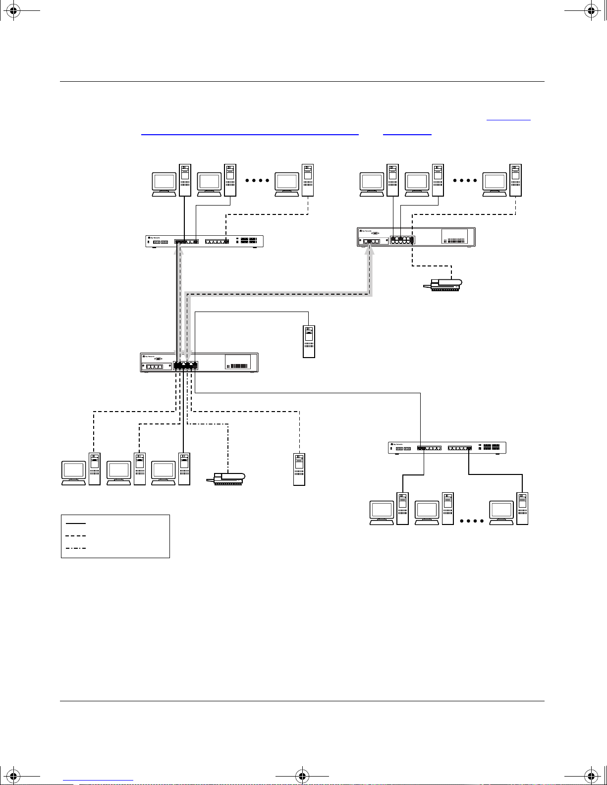
kombk.book Page 32 Thursday, February 18, 1999 10:59 AM
Using the BayStack 350 10/100/1000 Series Switch
The connection to S2 requires only one link between the switches because S1 and
S2 are both BayStack 350 switches that support 802.1Q tagging (see “VLANS
Spanning Multiple 802.1Q Tagged Switches” on page 1-23).
Non-802.1Q
tagging switch
S4
Untagged ports
(STP disabled)
BayStack 350-12T
S1
V2 V2 V1
Key
VLAN 1 (PVID=1)
VLAN 2 (PVID=2)
VLAN 3 (PVID=3)
V3
BayStack 350-12T
S2
Both ports are tagged
members of VLAN 1
and VLAN 2
V1
V2
Non-802.1Q
tagging switch
S3
BS35020A
Figure 1-23. VLAN Configuration Spanning Multiple Switches
1-32
304376-B Rev 00
Page 57

kombk.book Page 33 Thursday, February 18, 1999 10:59 AM
VLAN Configuration Rules
VLANs operate according to specif ic conf igu ration rule s. When creating VLANs ,
consider th e following rules that determine how the configured VLAN reacts in
any network topology:
• All ports that are involved in port mirroring must have memberships in the
same VLANs. If a port is configured for port mirroring, the port’s VLAN
membership cannot be changed.
• If a port is a trunk group member, all trunk members are added or deleted
from the VLAN.
• All ports involved in trunking and port mirroring must have the same VLAN
configuration. If a port is on a trunk with a mirroring port, the VLAN
configuration cannot be changed.
BayStack 350 10/100/1000 Series Switches
• VLANs are not dependent on Rate Limiting settings.
• If a port is an IGMP member on any VLAN, and is removed from a VLAN,
the port’s IGMP membership is also removed.
• If a port is added to a different VLAN, and it is already configured as a Static
Router port, the port is configured as an IGMP member on that specific
VLAN.
• The following gigabit MDA restriction applies for VLAN configurations:
tagging is restrict ed o n seconda ry VLANS to eit her all t agged or all untagged.
For more information about configuring VLANs, see “VLAN Configuration
Menu” on page 3-20.
See also Appendix C, “Quick Steps to Features” for configuration flowcharts that
can help you use this feature.
304376-B Rev 00
1-33
Page 58

kombk.book Page 34 Thursday, February 18, 1999 10:59 AM
Using the BayStack 350 10/100/1000 Series Switch
IGMP Snooping
BayStack 350 switches can sense IGMP Host Membe rshi p Reports from atta ched
stations and can use this information to set up a dedicated path between the
requesting stat ion and a local IP Multica st router. Once the pathway is est ablished ,
the BayStack 350 switch blocks the IP Multicast stream from exiting any other
port that does not connect to another Host Member, thus conserving bandwidth.
The following describes how BayStack 350 switches provide the same benefit as
IP Multicas t routers, but in the local area:
IGMP (internet group management protocol) is a protocol (see RFC 2236) that is
used by IP Multi cast r outer s to lea rn the existence of host grou p member s on thei r
directly attached subnets. The IP Multicast routers learn about the existence of
host groups by broadcasting IGMP queries and listening for IP hosts reporting
their host group memberships. This process is useful for the client/server
relationsh ip that exists between an IP Multicast source that provides data streams
to clients wanting to receive the data.
Figure 1-24
shows how IGMP is used to set up the path between the client and
server. As shown in this example, the IGMP host provides an IP Multicast stream
to designa ted routers w hich only forward the IP Multicast stream on their local
network if there is a recipient.
The client/server path is set up as follows:
1.
The designated router sends out a Host Membership Query to the subnet and
receives Host Membership Reports from end stations on the subnet.
2.
The designated routers then set up a path between the IP Multicast stream
source and the end stations.
3.
Periodically, the router continues to query end stations on whet her to conti nue
participation.
4.
As long as any client continues to participate, all clients, including
non-participating endstations on that subnet, receive the IP Multicast stream.
Note:
Although the non-participating endstations can filter the IP Multicast
traffic, the IP Multicast still exists on the subnet and consumes b andwidth.
IP Multicast can be optimized in a LAN by using IP Multicast filtering switches,
such as the BayStack 350 10/100/1000 Series Switches.
1-34
304376-B Rev 00
Page 59
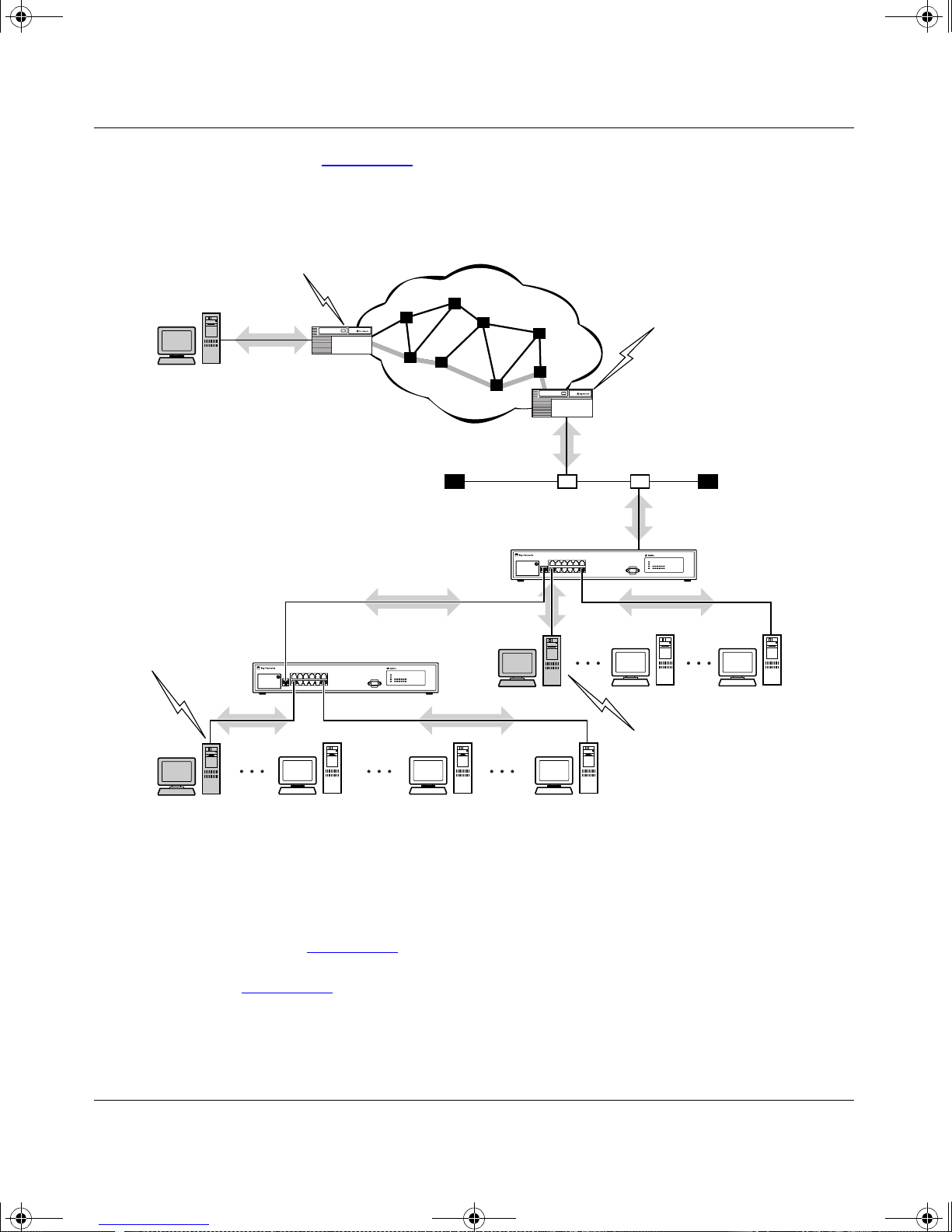
kombk.book Page 35 Thursday, February 18, 1999 10:59 AM
As shown in Figure 1-24, a non-IP Multicast filtering switch causes IP Multicast
traffic to be sent to all segments on the local subnet.
Host
Membership
IGMP
Host
Query
Designated
router #1
BayStack 350 10/100/1000 Series Switches
Internet
Designated
router #2
Host
Membership
Query
Non-multicast
filtering switch
Multicast stream
Host
Membership
Report
Non-multicast
filtering switch
304
Figure 1-24. IP Multicast Propagation with IGMP Routing
The BayStack 350 10/100/1000 Series Switches can automatically set up IP
Multicast filters so the IP Multicast traffic is only directed to the par ti cipating end
nodes (see Figure 1-25
).
304
Host
Membership
Report
BS35021A
In Figure 1-25
router. The router periodically sends Host Membership Queries to the LAN and
listens for a response from end stations. All of the clients connected to switches
S1 to S4 are aware of the queries from the router.
304376-B Rev 00
, switches S1 to S4 represent a LAN connected to an IP Multicast
1-35
Page 60
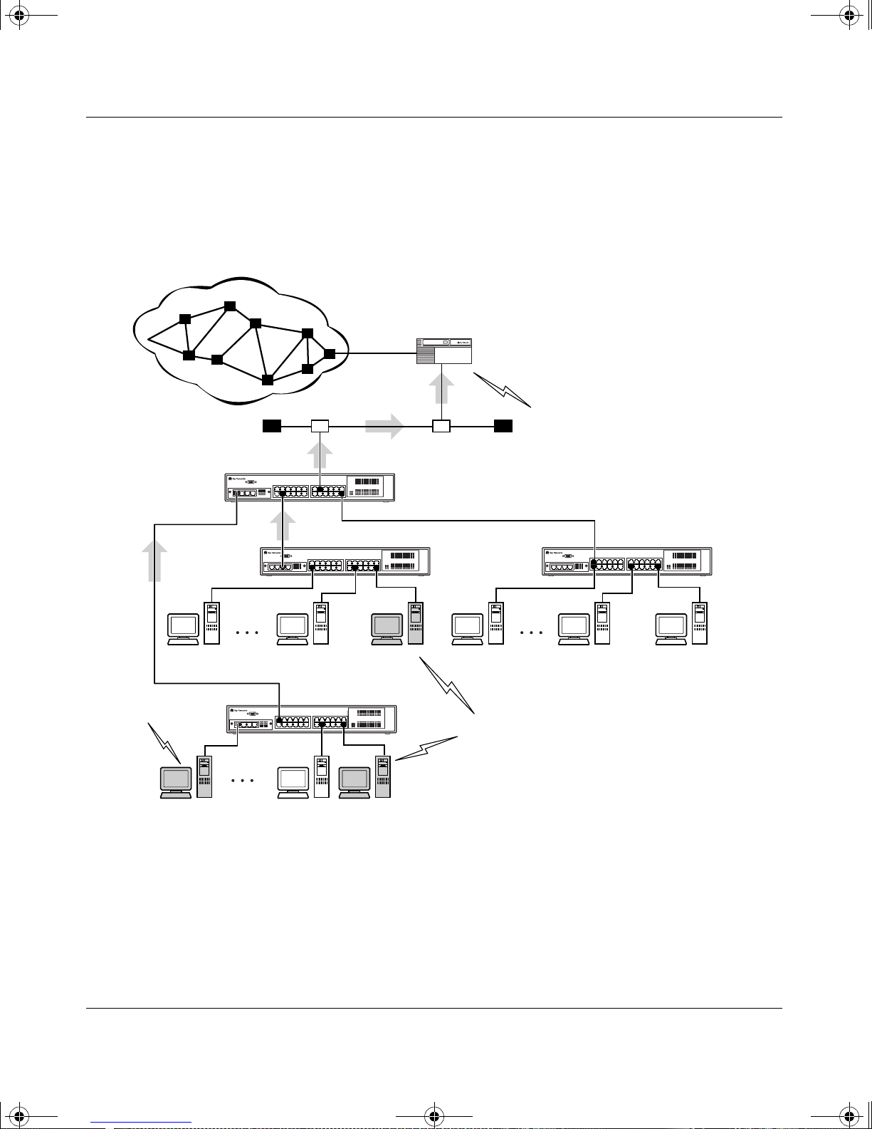
kombk.book Page 36 Thursday, February 18, 1999 10:59 AM
Using the BayStack 350 10/100/1000 Series Switch
One client, connected to S2, responds with a host membership report. Switch S2
intercepts the report from that port, a nd generate s a proxy repor t to its upstream
neighbor, S1. Also, two clients connected to S4 respond with host membership
reports, causing S4 to intercept the reports and to generate a consolidated proxy
report to its upstream neighbor, S1.
Internet
Designated
router
Host
Membership
Report
Proxy
S1
S4
S2
Consolidated
report
Proxy
BayStack 350-24T
switch
Host
Membership
Query
BayStack 350-24T
switch
BayStack 350-24T
switches
S3
Host
Membership
Report
Figure 1-25. BayStack 350-24T Filtering IP Multicast Streams (1 of 2)
Switch S1 treats the consolidated pr oxy reports fr om S2 and S4 as if they were
reports from any client connected to its ports, and generates a consolidated proxy
report to the designated router. In this way, the router receives a single
consolidated report from that entire subnet.
1-36
BS35022A
304376-B Rev 00
Page 61
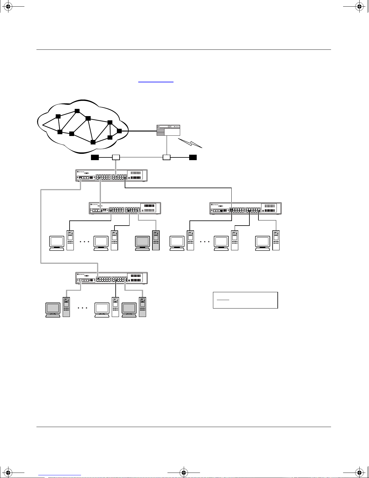
kombk.book Page 37 Thursday, February 18, 1999 10:59 AM
After the switches learn which ports are requesting access to the IP Multicast
stream, all other ports no t responding to t he queries are bl ocked from recei ving the
IP Multicast (see Figure 1-26
Internet
S1
BayStack 350 10/100/1000 Series Switches
).
Designated
router
Host
Membership
Query
BayStack 350-24T
switch
BayStack 350-24T
switches
S2
BayStack 350-24T
switch
S4
S3
Key
Multicast stream
BS35023A
Figure 1-26. BayStack 350-24T switches Filtering IP Multicast Stream (2 of 2)
304376-B Rev 00
1-37
Page 62

kombk.book Page 38 Thursday, February 18, 1999 10:59 AM
Using the BayStack 350 10/100/1000 Series Switch
IGMP Snooping Configuration Rules
The IGMP Snooping feature operates according to specific configuration rules.
When configuring your switch for IGMP Snooping, consider the following rules
that determine how the configuration reacts in any network topology:
• A port that is configured for port mirroring cannot be configured as a Static
Router port.
• If a MultiLink trunk member is configured as a Static Router port, all of the
MultiLink trunk members are configured as Static Router ports. Also, if a
Static Router port is removed, and it is a MultiLink trunk member, all
MultiLink trunk members are removed as Static Router port members,
automatically.
• Static Router ports must be port members of at least one VLAN.
• If a port is configured as a Static Router port, it is configured as a Static
Router port for all VLANs on that port. The IGMP configuration is
propagated through all VLANs of that port.
• If a Static Router port is removed, the membership for that port is removed
from all VLANs of that port.
• The IGMP Snooping feature is not STP dependent.
• The IGMP Snooping feature is not Rate Limiting dependent.
• The Snooping field must be enabled for the Proxy field to have any valid
meaning.
• Static Router ports are configured per VLAN and per IGMP Version.
Note:
Because IGMP Snooping is set up per VLAN, all IGMP changes are
implemente d according to the VLAN configuration for the specified ports.
For more information about using the IGMP Snooping feature, see “IGMP
Configuration” on page 3-48.
See also Appendix C, “Quick Steps to Features” for configuration flowcharts that
can help you use this feature.
1-38
304376-B Rev 00
Page 63
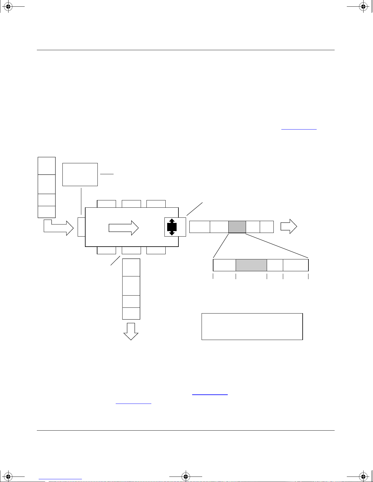
kombk.book Page 39 Thursday, February 18, 1999 10:59 AM
IEEE 802.1p Prio ritizing
You can use the VLAN Configuration screens to prioritize the order in which the
switch forwards packets, on a per-port basis. For example, if messages from a
specific segment are crucial to your operation, you can set the switch port
connected to th at se gment to a hi gher prior ity level ( by def ault , all swi tch port s are
set to Low priority). Untagged packets received by the switch on that port are
tagged acc ording to the priority level you assign to the port (see Figure 1-27
Before
BayStack 350 10/100/1000 Series Switches
).
CRC
Data
SA
DA
PVID = 2
Priority = 6
Port 1
802.1Q Switch
Port 4
Port 6 Port 7 Port 8
Untagged member
of VLAN 2
Outgoing
untagged packet
(unchanged)
Port configuration
parameters
Port 2 Port 3
Port 5
transmit
queue
CRC
Data
SA
DA
High
Low
Tagged member
of VLAN 2 (Port 5)
Port 5
(*Recalculated)
Key
Priority
CFI
VID
DASADataCRC* Tag
8100 CFI
16 bits 3 bits 1 bit 12 bits
After
- User_priority
- Canonical format indicator
- VLAN identifier
VID = 2Priority = 6
Figure 1-27. Prioritizing Packets
The newly tagged frame i s read within t he switch a nd sen t to t he port’s high or low
transmit queue for disposition (see Figure 1-28
shown in Figure 1-28
304376-B Rev 00
BS35024A
). The port transmit queue example
applies to all ports on the BayStack 350 switch.
1-39
Page 64
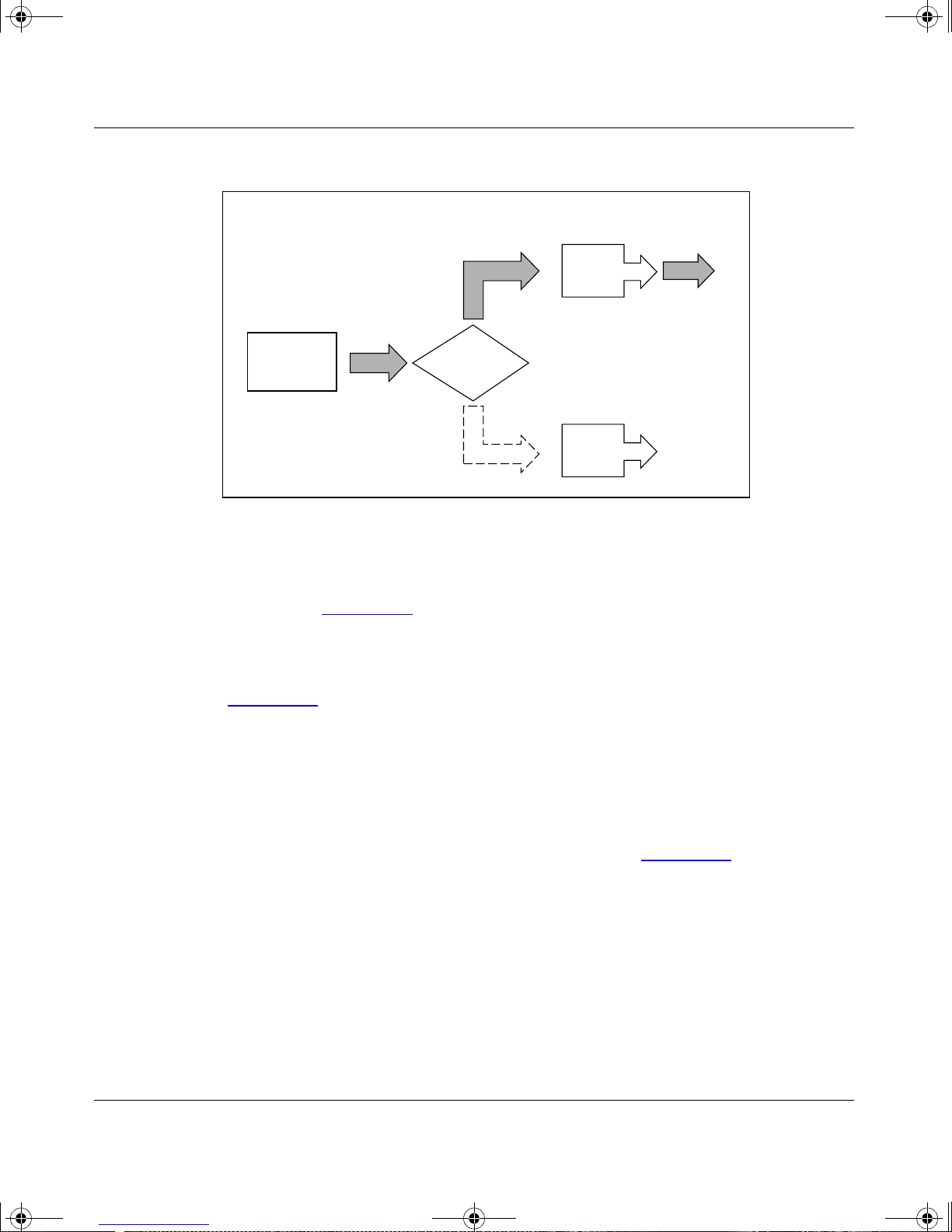
kombk.book Page 40 Thursday, February 18, 1999 10:59 AM
Using the BayStack 350 10/100/1000 Series Switch
Port 5
User priority
(6)
Port
transmit
queue
Traffic
class
7
6
High
5
4
3
2
Low
1
0
High priority
packet
BS35025A
Figure 1-28. Port Transmit Queue
As shown in Figure 1-28, the switch provides two transmission queues, a High
transmission queue and a Low transmissi on queue, for any given port . Fra mes ar e
assigned to one of these queues on the basis of user_priority using a traffic class
table. This table is managed by using the Traffic Class Configuration screen
(Figure 1-29
). The table indicates the corresponding traffic class that is assigned
to the fram e, for each possible user_priority value. If the frame leaves the switch
formatted as a tagged packet, the traffic class assign ed to the fram e is carried
forward to the next 802.1p capable switch. This allows the packet to carry the
assigned traffic class priority through the network until it reaches its destination.
The following steps show how to use the Traffic Class Configuration screen to
configure the port priority level shown in the example Figure 1-27
For more information about using the Traffic Class Configuration screen, see
“VLAN Configuration” on page 3-22.
1-40
.
304376-B Rev 00
Page 65

kombk.book Page 41 Thursday, February 18, 1999 10:59 AM
To configure the port p riority level, follow these steps:
1.
Determine the priority level you want to assign to the switch port.
User priority levels are assigne d defaul t settin gs in all BayStack 350 swit ches.
The range is from 0 to 7. The traffic class table can be modified. Therefore,
view the settings shown in the Traffic Class Configuration screen before
setting the port priority in the VLAN Port Configuration screen.
2.
Select Switch Configuration from the BayStack 450-12T Main Menu (or
press w).
3.
From the Switch Configuration Menu, select VLAN Configuration (or
press v).
4.
From the VLAN Configuration Menu, select Traffic Class Configuration
(or press t).
BayStack 350 10/100/1000 Series Switches
The Traffic Class Configuration screen opens (Figure 1-29
Traffic Class Configuration
User Priority Traffic Class
------------- ------------ Priority 0: [ Low ]
Priority 1: [ Low ]
Priority 2: [ Low ]
Priority 3: [ Low ]
Priority 4: [ Low ]
Priority 5: [ Low ]
Priority 6: [ Low ]
Priority 7: [ Low ]
Use space bar to display choices, press <Return> or <Enter> to select choice.
Press Ctrl-R to return to previous menu. Press Ctrl-C to return to Main Menu.
).
Figure 1-29. Default Traffic Class Configuration Screen Example
304376-B Rev 00
1-41
Page 66

kombk.book Page 42 Thursday, February 18, 1999 10:59 AM
Using the BayStack 350 10/100/1000 Series Switch
5.
Select a priority level from the range shown in the Traffic Class
Configurat ion scr een (or modify th e Traffic Class parameters to suit y ou r
needs).
6.
Assign the priority level to ports using the VLAN Port Configuration
screen:
a.
Press [Ctrl]-R to return to the VLAN Configuration Menu.
b.
From the VLAN Configuration Menu, select VLAN Port
Configuration (or press c).
The VLAN Port Configuration screen opens (Figure 1-30
Figure 1-30
Figure 1-27
VLAN Port Configuration
Port: [ 4 ]
Filter Tagged Frames: [ No ]
Filter Untagged Frames: [ No ]
Filter Unregistered Frames: [ No ]
Port Name: [ Principal's port ]
PVID: [ 2 ]
Port Priority: [ 6 ]
shows the VLAN Port Configuration screen setup for port 4 in
on page 1-39.
).
Use space bar to display choices, press <Return> or <Enter> to select choice.
Press Ctrl-R to return to previous menu. Press Ctrl-C to return to Main Menu.
Figure 1-30. Setting Port Priority Example
For more information about using this feature, see “VLAN Configuration Menu”
on page 3-20.
1-42
304376-B Rev 00
Page 67
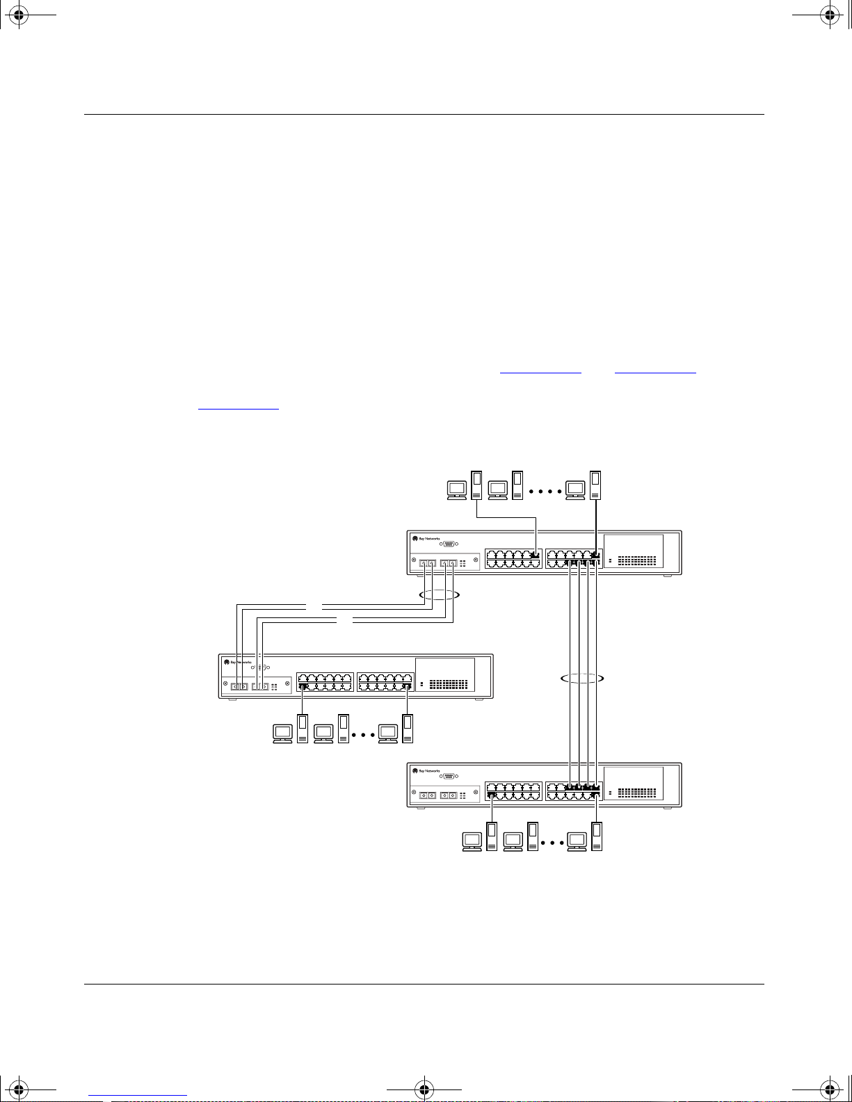
kombk.book Page 43 Thursday, February 18, 1999 10:59 AM
MultiLink Trunks
MultiLink trunks allow you to group up to four switch ports together to form a
link to another switch or server, thus increasing aggregate throughput of the
interconnection between the devices (up to 800 Mb/s in full-duplex mode).
BayStack 350 switches can be configured with up to six MultiLink trunks.
MultiLink Trunking software detects misconfigured (or broken) trunk links and
redirects traffi c on t he mi sc onfigured or br ok en trunk link to ot he r trunk members
within that trunk.
You can use the Trunk Configuration screen to create switch-to-switch and
switch-to-server MultiLink trunk links (see Figure 1-31
BayStack 350 10/100/1000 Series Switches
and Figure 1-32).
Figure 1-31
and S3.
S2
shows two trunks (T1 and T2) connecting switch S1 to switches S2
S1
T1
F
F
T2
S3
Figure 1-31. Switch-to-Switch Trunk Configuration Example
304376-B Rev 00
BS35026A
1-43
Page 68
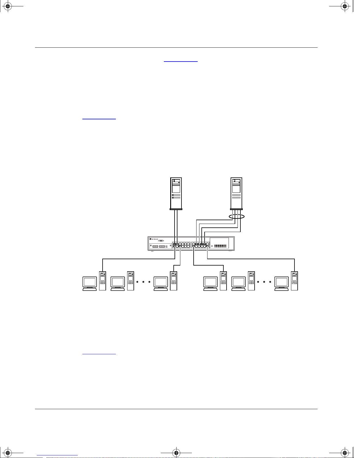
kombk.book Page 44 Thursday, February 18, 1999 10:59 AM
Using the BayStack 350 10/100/1000 Series Switch
Each of the trunks shown in Figure 1-3 1 can be configur ed wit h up to fou r swit ch
ports to provide up to 800 Mb/s aggregate bandwidth through each trunk, in
full-duplex mode. As shown in this example, when traffic between
switch-to-switch connections approaches single port bandwidth limitations,
creating a MultiLink trunk can supply the additional bandwidth required to
improve the performance.
Figure 1-32
shows a typica l switc h-to- serv er trunk configuration. I n this e xampl e,
file server FS1 utilizes dual MAC addresses, using one MAC address for each
Network interface controller (NIC). For this reason, FS1 does not require a trunk
assignment. FS2 is a single MAC server (with a four-port NIC) and is set up as
trunk configuration T1.
FS1
S1
FS2
T1
Figure 1-32. Switch-to-Server Trunk Configuration Example
Client/Server Configuration Utilizing MultiLink Trunks
Figure 1-33 shows an example of how MultiLink trunking can be used in a
client/server conf iguration. In this example, both servers are connected directl y t o
switch S1. FS2 is connected through a trunk configuration (T1). The
switch-to-switch connections are through trunks (T2, T3, T4, and T5).
1-44
BS35027A
304376-B Rev 00
Page 69
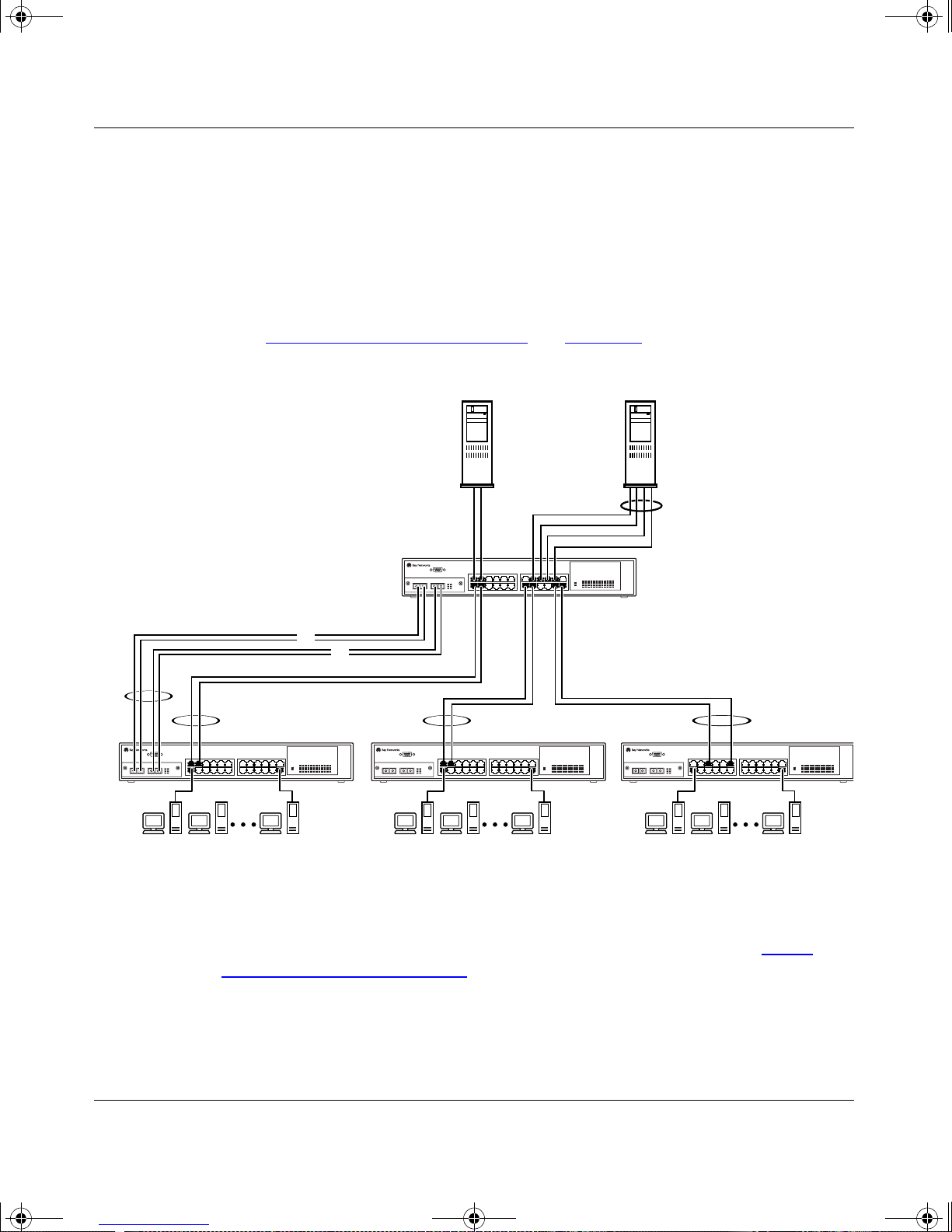
A
kombk.book Page 45 Thursday, February 18, 1999 10:59 AM
Clients accessing data from the servers (FS1 and FS2) are provided with
maximized bandwidth through trunks T1, T2, T3, T4, and T5. Trunk members
(the ports making up each trunk) do not have to be consecutive switch ports; they
can be selected randomly, as shown by T5.
With spanning tree enabled, one of the trunks (T2 or T3) acts as a redundant
(backup) trunk to switch S2. With spanning tree disabled, trunks T2 and T3 must
be configured into separate VLANs for this configuration to function properly
(see “IEEE 802.1Q VLAN Workgroups
BayStack 350 10/100/1000 Series Switches
” on page 1-18).
T2
S2
FS1
S1
F
F
T3 T4
S3
S4
FS2
T1
T5
Figure 1-33. Client/Server Configuration Example
The Trunk Configuration screens for switches S1 to S4 a r e shown in “Trunk
Configurat ion Scr een Exampl es” following this se ction. For detail ed information
about configuring trunks, see “MultiLink Trunk Configuration” on page 3-35.
304376-B Rev 00
BS35028
1-45
Page 70

kombk.book Page 46 Thursday, February 18, 1999 10:59 AM
Using the BayStack 350 10/100/1000 Series Switch
Trunk Configuration Screen Examples
This section shows examples of the MultiLink Trunk Configuration screens for
the client/server configuration example shown in Figure 1-33
screens show how you could set up the trunk configuration screens for switches
S1 to S4. For more information, see “Spanning Tree Considerations
page 1-57
Trunk Configuration Screen for Switch S1
Switch S1 is set up with five trunk configurations: T1, T2, T3, T4, and T5.
Setting up the Trunk Configuration For S1:
To set up the trunk configuration, choose MultiLink Trunk Configuration
(or press t) from the MultiLink Trunk Configuration Menu screen (Figure 1-34
, and “MultiLink Trunk Configuration” on page 3-35.
on page 1-45. The
” on
).
MultiLink Trunk Configuration Menu
MultiLink Trunk Configuration...
MultiLink Trunk Utilization...
Return to Switch Configuration Menu
Use arrow keys to highlight option, press <Return> or <Enter> to select option.
Press Ctrl-R to return to previous menu. Press Ctrl-C to return to Main Menu.
Figure 1-34. Choosing the MultiLink Trunk Configuration Screen
1-46
304376-B Rev 00
Page 71

kombk.book Page 47 Thursday, February 18, 1999 10:59 AM
The MultiLink Trunk Configuration screen opens (Figure 1-35).
MultiLink Trunk Configuration
Trunk Trunk Members STP Learning Trunk Mode Trunk Status
----- ---------------------------- ------------ --------------- ----------- 1 [ 15 ][ 17 ][ 19 ][ 21 ] [ Normal ] Basic [ Enabled ]
2 [ 25 ][ 26 ][ ][ ] [ Normal ] Basic [ Enabled ]
3 [ 2 ][ 4 ][ ][ ] [ Normal ] Basic [ Enabled ]
4 [ 14 ][ 16 ][ ][ ] [ Normal ] Basic [ Enabled ]
5 [ 22 ][ 24 ][ ][ ] [ Fast ] Basic [ Enabled ]
6 [ ][ ][ ][ ] [ Disabled ] Basic [ Disabled ]
Trunk Trunk Name
----- ------------------ 1 [ S1:T1 to FS2 ]
2 [ S1:T2 to S2 ]
3 [ S1:T3 to S2 ]
4 [ S1:T4 to S3 ]
5 [ S1:T5 to S4 ]
6 [ Trunk #6 ]
BayStack 350 10/100/1000 Series Switches
Use space bar to display choices, press <Return> or <Enter> to select choice.
Press Ctrl-R to return to previous menu. Press Ctrl-C to return to Main Menu.
Figure 1-35. MultiLink Trunk Configuration Screen for Switch S1
The MultiLink Trunk Conf iguration screen for swi tc h S1 i s configured as follows:
• Trunk (read only) indicates the trunks (1 to 6) that correspond to the switch
ports specified in the Trunk Members fields.
• Trunk Members indicates the ports that can be configured, in each row, to
create the corresponding trunk:
Ports 15, 17, 19, and 21 are assigned as trunk members of trunk 1.
Ports 25 and 26 are assigned as trunk members of trunk 2.
Ports 2 and 4 are assigned as trunk members of trunk 3.
Ports 14 and 16 are assigned as trunk members of trunk 4.
Ports 22 and 24 are assigned as trunk members of trunk 5.
304376-B Rev 00
1-47
Page 72

kombk.book Page 48 Thursday, February 18, 1999 10:59 AM
Using the BayStack 350 10/100/1000 Series Switch
• STP Learning indicates the spanni ng tr ee par tici patio n s ettin g for each of the
trunks:
Trunks 1 through 4 are enabled for Normal STP Learning.
Trunk 5 is enabled for Fast STP Learning.
• Trunk Mode (read only) indicates the trunk mode for each of the trunks:
The Trunk Mode field values for trunks 1 to 5 are set to Basic. Source MAC
addresses are statically assigned to specific trunk members for flooding and
forwarding. This allows the switch to stabilize and distribute the data streams
of source addresses across the trunk members.
• Trunk Status indicates the trunk status for each of the trunks. When set to
Enabled, the configuration settings for that specific trun k are activated.
• Trunk Name indicates optional fields for assigning names to the
corresponding configured trunks.
The names chosen for this example provide meaningful information to the
user of this swit ch (for e xampl e, S1:T1 to FS2 ind icate s that tru nk 1, in swit ch
S1, connects to file server 2).
1-48
304376-B Rev 00
Page 73

kombk.book Page 49 Thursday, February 18, 1999 10:59 AM
Trunk Configuration Screen for Switch S2
BayStack 350 10/100/1000 Series Switches
As shown in Figure 1-33
on page 1-45, switch S2 is set up with two trunk
configurations (T2 and T3). Both trunks connect directly to switch S1.
As in the previous screen examples, to set up a trunk configuration choose
MultiLink Trunk Configuration from the MultiLink Trunk Configuration Menu
screen.
Figure 1-36
MultiLink Trunk Configuration
Trunk Trunk Members STP Learning Trunk Mode Trunk Status
----- ---------------------------- ------------ --------------- ----------- 1 [ 25 ][ 26 ][ ][ ] [ Normal ] Basic [ Enabled ]
2 [ 1 ][ 3 ][ ][ ] [ Normal ] Basic [ Enabled ]
3 [ ][ ][ ][ ] [ Normal ] Basic [ Disabled ]
4 [ ][ ][ ][ ] [ Normal ] Basic [ Disabled ]
5 [ ][ ][ ][ ] [ Normal ] Basic [ Disabled ]
6 [ ][ ][ ][ ] [ Normal ] Basic [ Disabled ]
Trunk Trunk Name
----- ----------------- 1 [ S2:T2 to S1 ]
2 [ S2:T3 to S1 ]
3 [ Trunk #3 ]
4 [ Trunk #4 ]
5 [ Trunk #5 ]
6 [ Trunk #6 ]
shows the MultiLink Trunk Configuration screen for switch S2.
Use space bar to display choices, press <Return> or <Enter> to select choice.
Press Ctrl-R to return to previous menu. Press Ctrl-C to return to Main Menu.
Figure 1-36. MultiLink Trunk Configuration Screen for Switch S2
The MultiLink Trunk Conf iguration screen for swi tc h S2 i s configured as follows:
• Trunk (read on ly) indicates the trunks (1 to 6) t hat corresponds to the switch
ports specified in the Trunk Members fields.
• Trunk Members indicates the ports that can be configured, in each row, to
create the corresponding trunk:
Ports 25 and 26 are assigned as trunk members of trunk 1.
304376-B Rev 00
1-49
Page 74

kombk.book Page 50 Thursday, February 18, 1999 10:59 AM
Using the BayStack 350 10/100/1000 Series Switch
Ports 1 and 3 are assigned as trunk members of trunk 2.
• STP Learning indicates the spanni ng tr ee par tici pat ion s ettin g for ea ch of the
trunks:
Trunks 1 and 2 are enabled for Normal STP Learning.
• Trunk Mode (read only) indicates the trunk mode for each of the trunks:
The T run k Mode field values for trunks 1 and 2 are set to Basic. Source MAC
addresses are statically assigned to specific trunk members for flooding and
forwarding. This allows the switch to stabilize and distribute the data streams
of source addresses across the trunk members.
• Trunk Status indicates the trunk status for each of the trunks. When set to
Enabled, the configuration settings for that specific trun k are activated.
• Trunk Name indicates optional fields for assigning names to the
corresponding configured trunks.
The names chosen for this example provide meaningful information to the
user of this switch (for example, S2:T2 to S1 indicates that trunk 1, in switch
S2, connects to switch 1).
1-50
304376-B Rev 00
Page 75

kombk.book Page 51 Thursday, February 18, 1999 10:59 AM
Trunk Configuration Screen for Switch S3
BayStack 350 10/100/1000 Series Switches
As shown in Figure 1-33
on page 1-45, switch S3 is set up with one trunk
configuration (T4). This trunk connects directly to switch S1.
As in the previous screen examples, to set up an inter-switch trunk configuration
choose MultiLink Trunk Configuration from the MultiLink Trunk Configuration
Menu screen.
Figure 1-37
MultiLink Trunk Configuration
Trunk Trunk Members STP Learning Trunk Mode Trunk Status
----- ---------------------------- ------------ --------------- ----------- 1 [ 1 ][ 3 ][ ][ ] [ Normal ] Basic [ Enabled ]
2 [ ][ ][ ][ ] [ Normal ] Basic [ Disabled ]
3 [ ][ ][ ][ ] [ Normal ] Basic [ Disabled ]
4 [ ][ ][ ][ ] [ Normal ] Basic [ Disabled ]
5 [ ][ ][ ][ ] [ Normal ] Basic [ Disabled ]
6 [ ][ ][ ][ ] [ Normal ] Basic [ Disabled ]
Trunk Trunk Name
----- ----------------- 1 [ S3:T4 to S1 ]
2 [ Trunk #2 ]
3 [ Trunk #3 ]
4 [ Trunk #4 ]
5 [ Trunk #5 ]
6 [ Trunk #6 ]
shows the MultiLink Trunk Configuration screen for switch S3.
Use space bar to display choices, press <Return> or <Enter> to select choice.
Press Ctrl-R to return to previous menu. Press Ctrl-C to return to Main Menu.
Figure 1-37. MultiLink Trunk Configuration Screen for Switch S3
The MultiLink Trunk Conf iguration screen for swi tc h S3 i s configured as follows:
• Trunk (read only) indicates the trunks (1 to 6) that correspond to the switch
ports specified in the Trunk Members fields.
• Trunk Members indicates the ports that can be configured, in each row, to
create the corresponding trunk:
Ports 1 and 3 are assigned as trunk members of trunk 1.
304376-B Rev 00
1-51
Page 76

kombk.book Page 52 Thursday, February 18, 1999 10:59 AM
Using the BayStack 350 10/100/1000 Series Switch
• STP Learning indicates the spanni ng tr ee par tici patio n s ettin g for each of the
trunks:
Trunk 1 is enabled for Normal STP Learning.
• Trunk Mode (read only) indicates the trunk mode for each of the trunks:
The T runk Mode f iel d v alue for trunk 1 i s set t o Basic. Sou rce MAC addresses
are staticall y assig ned t o speci f ic t ru nk members f or flo oding an d fo rwar ding.
This allows the switch to stabilize and distribute the data streams of source
addresses across the trunk members.
• Trunk Status indicates the trunk status for each of the trunks. When set to
Enabled, the configuration settings for that specific trun k are activated.
• Trunk Name optional fields for assigning names to the corresponding
configured trunks.
The names chosen for this example provide meaningful information to the
user of this switch (for example, S3:T4 to S1 indicates that trunk 1, in switch
S3, connects to switch 1).
1-52
304376-B Rev 00
Page 77

kombk.book Page 53 Thursday, February 18, 1999 10:59 AM
Trunk Configuration Screen for Switch S4
BayStack 350 10/100/1000 Series Switches
As shown in Figure 1-33
, switch S4 is set up with one trunk configuration (T5).
This trunk connects directly to switch S1.
As in the previous screen examples, to set up a trunk configuration choose
MultiLink Trunk Configuration from the MultiLink Trunk Configuration Menu
screen.
Figure 1-38
MultiLink Trunk Configuration
Trunk Trunk Members STP Learning Trunk Mode Trunk Status
----- ---------------------------- ------------ --------------- ----------- 1 [ 5 ][ 11 ][ ][ ] [ Normal ] Basic [ Enabled ]
2 [ ][ ][ ][ ] [ Normal ] Basic [ Disabled ]
3 [ ][ ][ ][ ] [ Normal ] Basic [ Disabled ]
4 [ ][ ][ ][ ] [ Normal ] Basic [ Disabled ]
5 [ ][ ][ ][ ] [ Normal ] Basic [ Disabled ]
6 [ ][ ][ ][ ] [ Normal ] Basic [ Disabled ]
Trunk Trunk Name
----- ------------------ 1 [ S4:T5 to S1 ]
2 [ Trunk #2 ]
3 [ Trunk #3 ]
4 [ Trunk #4 ]
5 [ Trunk #5 ]
6 [ Trunk #6 ]
shows the MultiLink Trunk Configuration screen for switch S4.
Use space bar to display choices, press <Return> or <Enter> to select choice.
Press Ctrl-R to return to previous menu. Press Ctrl-C to return to Main Menu.
Figure 1-38. MultiLink Trunk Configuration Screen for Switch S4
304376-B Rev 00
1-53
Page 78

kombk.book Page 54 Thursday, February 18, 1999 10:59 AM
Using the BayStack 350 10/100/1000 Series Switch
The MultiLink Trunk Conf iguration screen for swi tc h S4 i s configured as follows:
• Trunk (read only) indicates the trunk (1 to 6) that corresponds to the switch
ports specified in the Trunk Members fields.
• Trunk Members (Unit/Port) indicates the ports that can be configured, in
each row, to create the corresponding trunk:
Ports 5 and 11 are assigned as trunk members of trunk T1.
• STP Learning indicates the spa nning tree par ticipat ion settin g for each of the
trunks:
Trunk 1 is enabled for Normal STP Learning.
• Trunk Mode (read only) indicates the Trunk Mode for each of the trunks:
The T runk Mode f iel d v alue for trunk 1 i s set t o Basic. Sou rce MAC addresses
are staticall y assig ned t o speci f ic t ru nk members f or flo oding an d fo rwar ding.
This allows the switch to stabilize and distribute the data streams of source
addresses across the trunk members.
• Trunk Status i ndicates the Trunk Status for eac h of the trunks. When it is set
to Enabled, the configuration settings for that specific tr unk are activated.
• Trunk Name optional fields for assigning names to the corresponding
configured trunks.
The names chosen for this example provide meaningful information to the
user (for example, S4:T5 to S1 indicates that Trunk 1, in switch S4, connects
to Switch 1).
1-54
304376-B Rev 00
Page 79

kombk.book Page 55 Thursday, February 18, 1999 10:59 AM
Before Configuring Trunks
When you create and enable a trunk, the trunk members (switch ports) take on
certain setti ngs nece ss ary for corr ect op era tion o f the M ulti Link Trunking feat ure.
These settings, al ong wi th s pec ific configuration rules, must be considered be for e
configuring your MultiLink trunk.
Before configuring any MultiLink trunk, follow these steps:
1.
Read the configuration rules provided in the next section, “MultiLink
Trunking Configuration Rules.”
BayStack 350 10/100/1000 Series Switches
2.
Determine which switch ports (up to four) are to become
(the specific ports making up the trunk):
a.
A minimum of two ports are required for each trunk.
b.
Ensure that the cho sen switc h ports ar e s et t o Enable d, using th e P ort
Configuration screen (see “Port Configuration” on page 3-30) or
through network management.
c.
Trunk member ports must be in the same VLAN.
3.
All network cabli ng should be co mplete and stabl e bef ore conf igur ing any
trunks, to avoid configuration errors.
4.
Consider how the existing spanning tree will react to the new trunk
configuration (see “Spanning Tree Considerations
5.
Consider how existing VLANs will be affected by the addition of a trunk.
6.
After completing the above steps, see “MultiLink Trunk Configuration”
on page 3-35 f or sc r een example s and f iel d descripti ons that wil l help y o u
configure your MultiLink trunks.
MultiLink Trunking Configuration Rules
trunk members
” on page 1-57).
The MultiLink Trunking feature is deterministic; that is, it operates according to
specific configuration rules. When creating trunks, consider the following rules
that determine how the MultiLink trunk reacts in any network topology:
• Any port that partic ipates in Mu ltiLink Trunkin g must be an active port (set to
Enabled via the Port Configuration screen or through network management).
304376-B Rev 00
1-55
Page 80

kombk.book Page 56 Thursday, February 18, 1999 10:59 AM
Using the BayStack 350 10/100/1000 Series Switch
• All trunk members must be co nfigured into the same VLAN before the Trunk
Configuration screen’s Trunk Status field can be set to Enabled (See “VLAN
Configuration” on page 3-22).
• When an acti ve p ort is conf igur ed in a trunk, the port bec omes a trunk member
as soon as the Trunk St atus f iel d is set to Ena bled. Af ter the Trunk St atus f ield
is set to Ena bled, the spanning tree parameters for th e port will ch ange to
reflect the new trunk settings.
• If spanning tree participation of any trunk member is changed (enabled or
disabled), the spanning tree participation of all members of that trunk is
changed similarly (see “Spanning Tree Considerations
• When a trunk is enabled, the trunk spanning tree participation setting takes
precedence over that of any trunk member. When a trunk is active, the trunk
STP setting can be changed f rom eithe r the Trunk Conf igur ation sc reen or the
Spanning Tree Configuration screen.
” on page 1-57.
• If the VLAN settings of any tr unk member are changed , the VLAN setti ngs of
all members of that trunk are changed similarly.
• When any trunk member is set to Disabled (not active) through the Port
Configuration screen or through network management, the trunk member is
removed from the trunk. The removed trunk member has to be reconfigured
through the Trunk Configuration screen to rejoin the trunk. A screen prompt
precedes this ac ti on. A t r unk membe r c annot be disabled if t here are only tw o
trunk members on the trunk.
• A trunk member cannot be configured as a monitor port (see “Port Mirroring
Configuration” on page 3-41).
• Trunks cannot be monitored by a monitor port; however, trunk members can
be monitored (see “Port-Based Mirroring Configuration
” on page 1-62).
• All trunk members must have identical IGMP Snooping configurations.
• If the IGMP Snooping configuration for any trunk member is changed, the
IGMP Snooping settings for all trunk members are changed.
1-56
304376-B Rev 00
Page 81
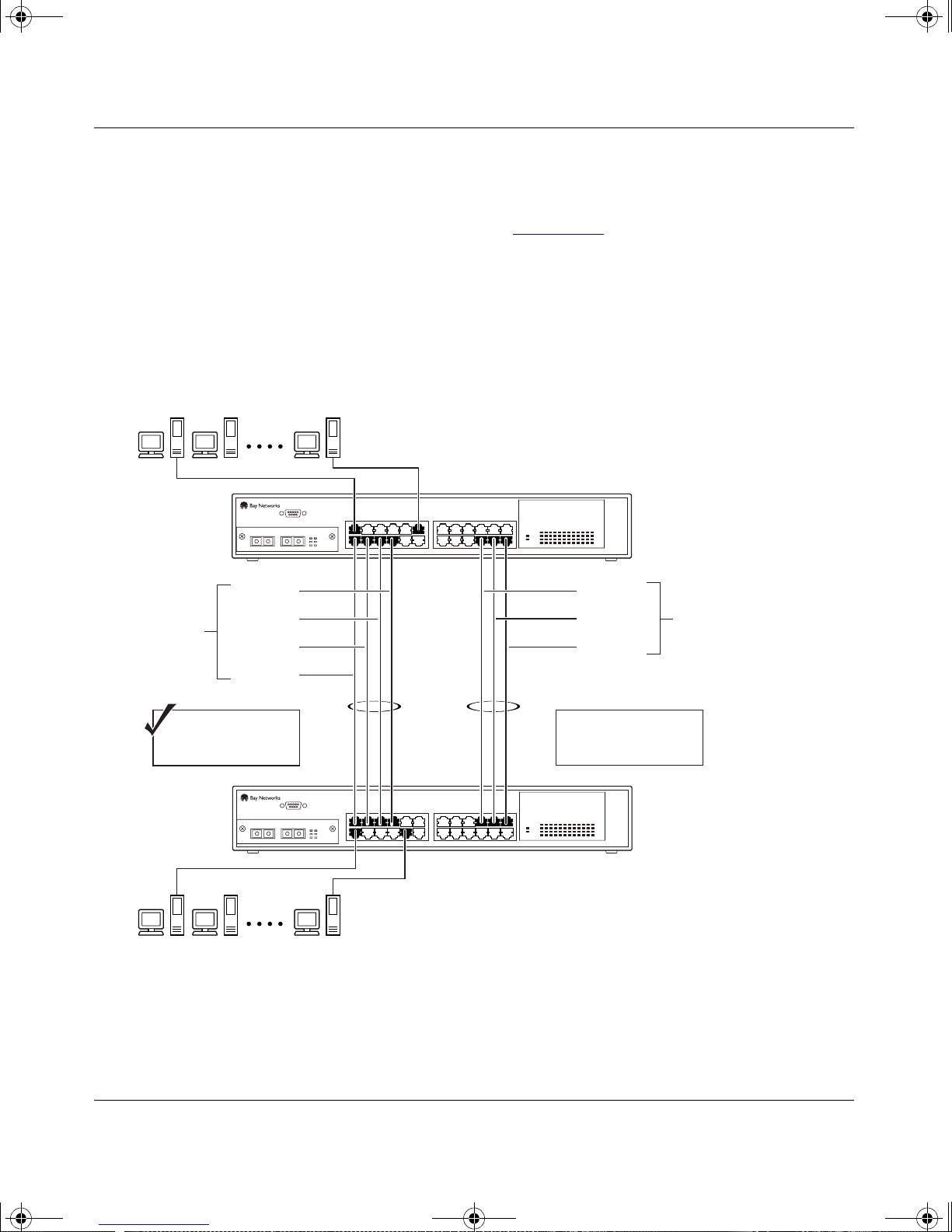
kombk.book Page 57 Thursday, February 18, 1999 10:59 AM
Spanning Tree Considerations
The spanning tree Path Cost parameter is recalculated based on the aggregate
bandwidth of the trunk. For example, Figure 1-39
with two port members operating at 100 Mb/s and the other two port members
operating at 10 Mb/s. Trunk T1 provides an aggregate bandwidth of 220 Mb/s.
The Path Cost for T1 is 4 (Path Cost = 1000/LAN speed, in Mb/s). If a second
three port trunk ( T2) is conf igu red with an aggr ega te bandwidt h of 210 Mb/s, wit h
a comparable P ath Cost of 4, the swi tch s oftw ar e choos es the trunk with t he larger
bandwidth (T1) to determine the most efficient path.
BayStack 350 10/100/1000 Series Switches
shows a four port trunk (T1)
Path Cost T1 = 4
Aggregate Bandwidth
S1
100 Mb/s
100 Mb/s
10 Mb/s
10 Mb/s
220 Mb/s
S2
T1 T2
100 Mb/s
100 Mb/s
10 Mb/s
Aggregate Bandwidth
210 Mb/s
Path Cost T2 = 4
BS35029A
Figure 1-39. Path Cost Arbitration Example
304376-B Rev 00
1-57
Page 82
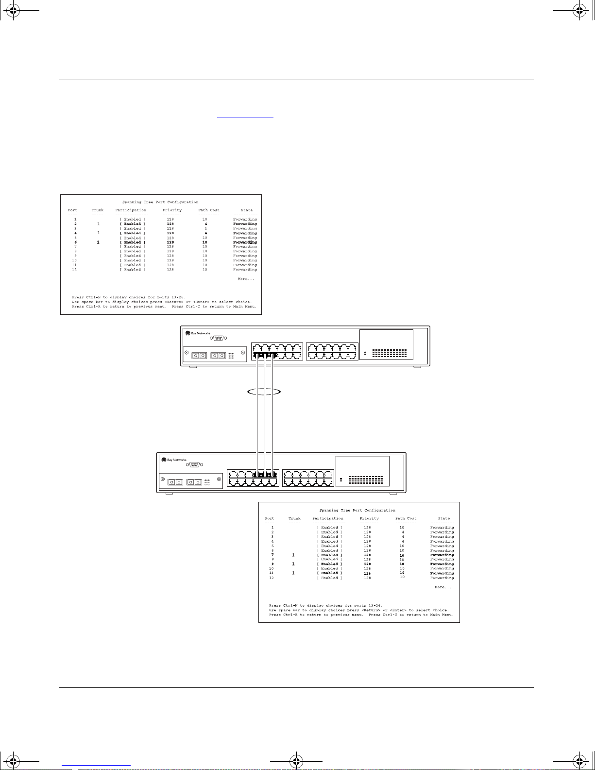
kombk.book Page 58 Thursday, February 18, 1999 10:59 AM
Using the BayStack 350 10/100/1000 Series Switch
The switch can also detect trunk member ports that are physically misconfigured.
For example, in Figure 1-40
configured correctly to trunk member ports 7, 9, and 11 of switch S2. The
Spanning Tree Port Configuration screen for each switch shows the port State
field for each port in the Forwarding state.
, trunk member ports 2, 4, and 6 of switch S1 are
S1 Port Configuration screen
S2
S1
T1
Figure 1-40. Example 1: Correctly Configured Trunk
1-58
S2 Port Configuration screen
BS35030A
304376-B Rev 00
Page 83
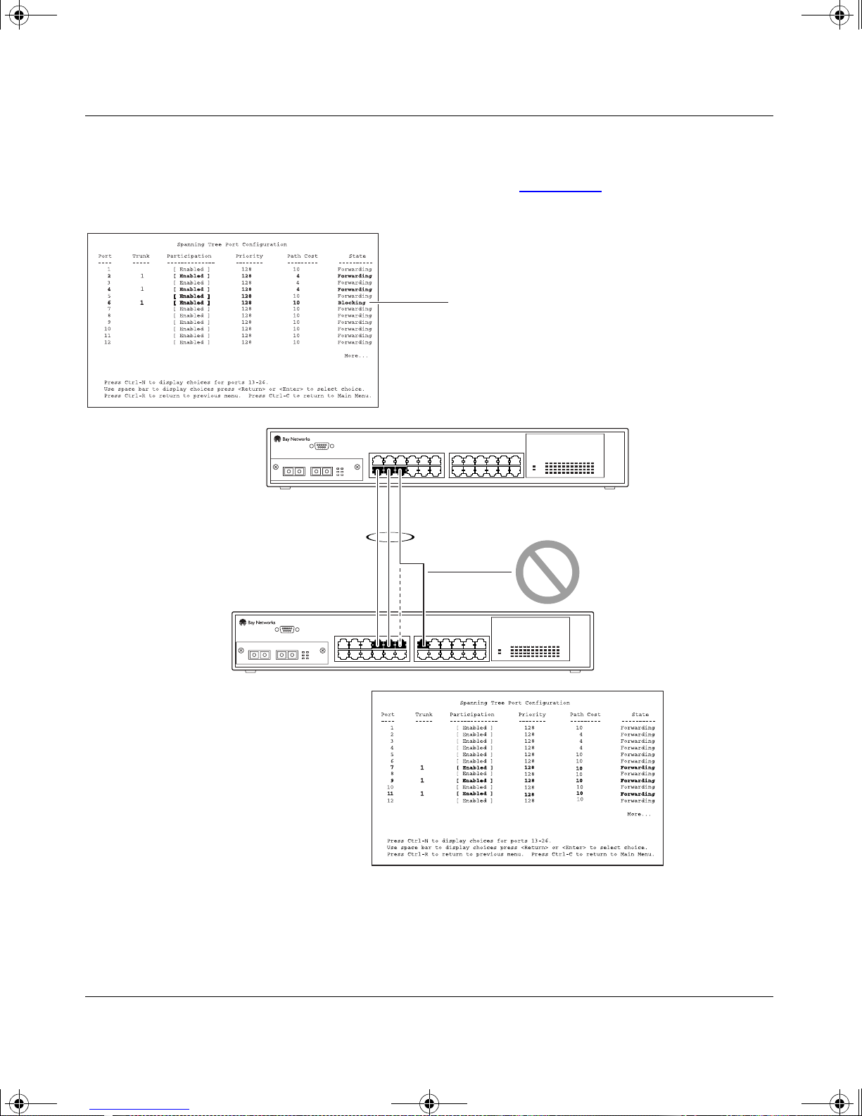
kombk.book Page 59 Thursday, February 18, 1999 10:59 AM
If switch S2’s trunk member port 11 is physically disconnected and then
reconnected to port 13, the Spanni ng T ree Por t Conf igurati on screen f or switch S1
changes to show port 6 in the Blocking state (Figure 1-41
BayStack 350 10/100/1000 Series Switches
).
S1 Port Configuration screen
S2
S1
[Blocking]
T1
Figure 1-41. Example 2: Detecting a Misconfigured Port
304376-B Rev 00
S2 Port Configuration screen
BS35031A
1-59
Page 84

kombk.book Page 60 Thursday, February 18, 1999 10:59 AM
Using the BayStack 350 10/100/1000 Series Switch
Additional Tips About the MultiLink Trunking Feature
When you create a MultiLink trunk, the individual trunk members (the specific
ports that make up the trunk) are logically connected and react as a single entity.
For example, if you change spanning tree parameters for any trunk member, the
spanning t ree parameters for all trunk members are changed.
All configured trunks are indicated in the Spanning Tree Configuration screen.
The screen’s Trunk field lists the active trunks, adjacent to the port numbers that
correspond to the specific trunk member for that trunk.
When a trunk i s act i ve you can di sable s panning tre e part i cipat ion us ing the Trunk
Configuration screen or using the Spanning Tree Configuration screen.
When a trunk is not active, the spanning tree participation setting in the Trunk
Configuration screen does not take effect until the Trunk Status field is set to
Enabled.
The trunk is also viewed by management stations as a single spanning tree port.
The spanning tree port is represented by the trunk member with the lowest port
number. For example, if ports 13, 14, 15, and 16 are trunk members of trunk T1,
the management station views trunk T1 as spanning tree port 13.
For more inf ormation a bout usin g the Mult iLink Trunking feature , see “Mul tiLink
Trunk Configuration” on page 3-35.
See also Appendix C, “Quick Steps to Features” for configuration flowcharts that
can help you use this feature.
1-60
304376-B Rev 00
Page 85
kombk.book Page 61 Thursday, February 18, 1999 10:59 AM
Port Mirroring (C onversation Steering)
You can designate one of your switch por ts to moni tor t raffic on an y tw o specified
switch ports (port-based) or to monitor traffic to or from any two specified
addresses that the switch has learned (address-based).
BayStack 350 10/100/1000 Series Switches
Note:
A probe device, such as the Bay Networks StackProbe™ or equivalent,
must be connected to the designated monitor port to use this feature (contact
your Bay Networks sales agent for details about the StackProbe).
The following sections provide example configurations for both monitoring
modes available with the Port Mirroring feature:
• Port-based Mirroring
• Address-based Mirroring
A sample of the Port Mirroring Configuration screen is provided with each of the
examples to support the network configuration example.
Note that in the following examples, the displayed screens do not show all of the
screen prompts that precede some actions. For example, when you configure a
switch for port mirroring or when you modify an existing port mirroring
configuration, the new configuration does not take effect until you respond [Yes]
to the following screen prompt:
Is your port mirroring configuration complete? [ Yes ]
304376-B Rev 00
1-61
Page 86
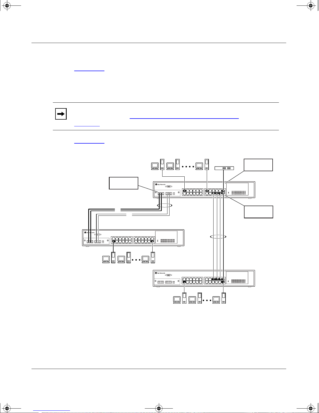
kombk.book Page 62 Thursday, February 18, 1999 10:59 AM
Using the BayStack 350 10/100/1000 Series Switch
Port-Based Mirroring Configuration
Figure 1-42 shows an exa mple of a port -b ased mir rori ng conf i gurat ion where por t
23 is designated as the monitor port for ports 24 and 25 of switch S1. Although
this example shows ports 24 and 25 monitored by the monitor port (port 23), any
of the trunk members of T1 and T2 can also be monitored.
Note:
Trunks cannot be monitored and trunk members cannot be configured
as monitor ports (see “
page 1-55
Figure 1-43
S2
).
shows t he Port Mirror in g Conf ig urati on scr een setup f or th is example.
Port X
(port 25)
F
F
MultiLink Trunking Configuration Rules” on
StackProbe
S1
T 1
T2
Monitor port
(port 23)
Port Y
(port 24)
Figure 1-42. Port-Based Mirroring Configuration Example
1-62
S3
BS35032A
304376-B Rev 00
Page 87

kombk.book Page 63 Thursday, February 18, 1999 10:59 AM
In the configuration example shown in Figure 1-42 on page 1-62, the designated
monitor port (port 23) can be set to monitor traffic in any of the following modes:
• Monitor all traffic received by port X.
• Monitor all traffic transmitted by port X.
• Monitor all traffic received and transmitted by port X.
• Monitor all traffic received by port X or transmitted by port Y.
• Monitor all traffic received by port X (destined to port Y) and then
transmitted by port Y.
• Monitor all traffic received/transmitted by port X and received/transmitted
by port Y (conversations between port X and port Y).
BayStack 350 10/100/1000 Series Switches
As shown in the Port Mirroring Configuration screen example (Figure 1-43
), a
user has designated port 23 as the Monitor Port for ports 24 and 25 in switch S1.
The Monitoring Mode field [ - > Port X or Port Y - > ] indicates that all traffic
receiv ed b y port X or all traff ic transmitted by port Y is currently being monitored
by the StackProbe attached to Monitor Port 23.
The screen data displayed at the bottom of the screen shows the currently active
port mirroring configuration.
304376-B Rev 00
1-63
Page 88

kombk.book Page 64 Thursday, February 18, 1999 10:59 AM
Using the BayStack 350 10/100/1000 Series Switch
Port Mirroring Configuration
Monitoring Mode: [ -> Port X or Port Y -> ]
Monitor Port: [ 23 ]
Port X: [ 25 ]
Port Y: [ 24 ]
Address A: [ 00-00-00-00-00-00 ]
Address B: [ 00-00-00-00-00-00 ]
Port mirroring configuration has taken effect.
Currently Active Port Mirroring Configuration
--------------------------------------------Monitoring Mode: -> Port X or Port Y -> Monitor Port: 23
Port X: 25 Port Y: 24
Use space bar to display choices, press <Return> or <Enter> to select choice.
Press Ctrl-R to return to previous menu. Press Ctrl-C to return to Main Menu.
Figure 1-43. Port Mirroring Port-Based Screen Example
Address-Based Mirroring Configuration
Figure 1-44 shows an e xampl e of a n address -based mirro ring c onf ig urati on where
port 23, the designated monitor port for switch S1, is monitoring traffic occurring
between address A and address B.
1-64
304376-B Rev 00
Page 89
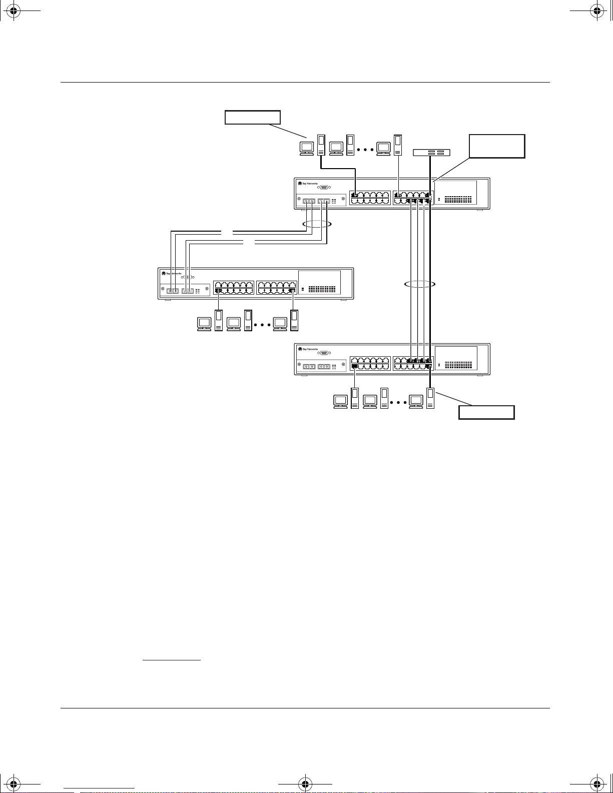
kombk.book Page 65 Thursday, February 18, 1999 10:59 AM
BayStack 350 10/100/1000 Series Switches
Address A
S2
StackProbe
S1
T1
F
F
T2
S3
Monitor port
(port 23)
Address B
BS35033A
304376-B Rev 00
Figure 1-44. Address-Based Mirroring Configuration Example
In this configuration, the designated monitor port (port 23) can be set to monitor
traffic in any of the following modes:
• Monitor all traffic transmitted from address A to any address.
• Monitor all traffic received by address A from any address.
• Monitor all traffic received by or transmitted by address A.
• Monitor all traffic transmitted by address A to address B.
• Monitor all traffic between address A and address B (conversation
between the two stations).
Figure 1-45
shows t he Port Mirror in g Conf ig urati on scr een setup f or th is example.
1-65
Page 90
kombk.book Page 66 Thursday, February 18, 1999 10:59 AM
Using the BayStack 350 10/100/1000 Series Switch
In this exa mple, port 23 becomes the designated Monitor Por t for s witch S1 when
you press [Enter] in response to the [Yes] screen prompt. The screen data
displayed at t he bottom of the scr een wil l change to show the ne w c urrently active
port mirroring configuration when you press Return.
The Monitoring Mode field [ Address A - > Address B ] indicates that all
traffic transmitted by address A to addr es s B wil l be moni tored by the St ack Probe
attached to Monitor Port 23.
Note:
When you enter MAC addresses in this screen, they are also displayed
in the MAC Address Table screen (see “MAC Address Table” on page 3-18).
Port Mirroring Configuration
Monitoring Mode: [ Address A -> Address B ]
Monitor Port: [ 23 ]
Port X: [ ]
Port Y: [ ]
Address A: [ 00-44-55-44-55-22 ]
Address B: [ 00-33-44-33-22-44 ]
Is your Port mirroring configuration complete? [ Yes ]
Currently Active Port Mirroring Configuration
--------------------------------------------Monitoring Mode: Address A <-> Address B Monitor Port: 23
Address A: 00-11-22-33-44-55 Address B: 22-33-44-55-66-77
Use space bar to display choices, press <Return> or <Enter> to select choice.
Press Ctrl-R to return to previous menu. Press Ctrl-C to return to Main Menu.
Figure 1-45. Port Mirroring Address-Based Screen Example
1-66
304376-B Rev 00
Page 91

kombk.book Page 67 Thursday, February 18, 1999 10:59 AM
Port Mirroring Configuration Rules
The following configuration rules must be applied to any port mirroring
configuration:
• A monitor port cannot be configured as a trunk member or IGMP member,
and cannot be used for normal switch functions.
• When a port is configured and enabled as a monitor port, the port is
automatically disabled from participating in the spanning tree. When the port
is reconfigured as a standard switch port (no longer a monitor port), the port
becomes enabled for spanning tree participation.
• When creating a port-based port mirroring configuration, be sure that the
monitor port and both of the mirrored ports, port X and port Y, have the same
configuration. Use the VLAN Configuration screen to configure the VLAN
(see “VLAN Configuration” on page 3-22).
BayStack 350 10/100/1000 Series Switches
• VLAN configuration settings for any ports configured for port-based
mirroring cannot be changed. Use the Port Mirroring Configuration screen to
disable port mirroring (or reconfigure the port mirroring ports), then change
the VLAN configuration settings.
• For port-based monitoring of traffic, use one of the following modes for
monitoring broadcast, IP Multicast, or unknown DA frames:
Monitor all traffic received by port X.
Monitor all traffic transmitted by port X.
Monitor all traffic received and transmitted by port X.
Monitor all traffic received by port X or transmitted by port Y.
For more information about using the Port Mirroring feature, see “Port Mirroring
Configuration” on page 3-41.
See also Appendix C, “Quick Steps to Features” for configuration flowcharts that
can help you use this feature.
304376-B Rev 00
1-67
Page 92

kombk.book Page 68 Thursday, February 18, 1999 10:59 AM
Page 93

kombk.book Page 1 Thursday, February 18, 1999 10:59 AM
This chapter provides the following information about the BayStack 350 switch:
• Ins tallation requirements
Chapter 2
Installing the BayStack 350 Switch
• Installation procedure
• Instructions for connecting power
• Instructions for verifying the installation
• Ins tructions for the initial switch setup
Refer to Chapter 3, “Using the Console Interface,” to further configure your
BayStack 350 switch.
Installation Requirement s
Before installing the BayStack 350 switch, verify that the package contains the
items shown in Figure 2-1
Note:
your region; see “AC Power Receptacle” on page 1-7.
Install the BaySta ck 350 switch in a vent ilated area tha t is dust free and a way from
heat vents, warm air exhaust from other equipment, and direct sunlight. Avoid
proximity to large electric motors or other electromagnetic equipment. When
choosing a location, observe the environmental guidelines listed in Appendix A,
“Technical Specifications.” You will need a Phillips screwdriver for the
installation.
Be sure that the supplied AC power cord matches the requirements for
.
304376-B Re v 00
2-1
Page 94
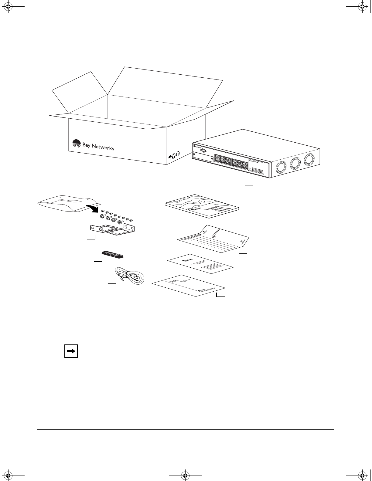
kombk.book Page 2 Thursday, February 18, 1999 10:59 AM
Using the BayStack 350 10/100/1000 Series Switch
Installation hardware:
Mounting
brackets
and screws
Rubber
footpads
AC
power cord
Figure 2-1. Package Contents
Note:
Your shipping box may be configured differently than shown in the
above example; the contents will be the same.
Documentation:
BayStack 350-24T switch
or BayStack 350-12T switch
Using the BayStack 350
10/100/1000 Series Switch
Owner registration card
Customer registration card
Release notes
BS35034A
The number of box es and their contents depends o n the options you order ed. Open
any accessories box and verify that the contents agree with your bill of materials.
If any items are missing or damaged, contact the sales agent or the customer
service representative from whom you purchased the BayStack 350 switch.
2-2
304376-B Rev 00
Page 95
kombk.book Page 3 Thursday, February 18, 1999 10:59 AM
Installatio n Proced ure
This section provides the requirements and instructions for installing the
BayStack 350 switch on a flat surface or in a standard 19-inch utility rack. If you
install the switch in a rack, ground the rack to the same grounding electrode used
by the po wer ser vice in the area . The ground path must be permanent and must not
exceed 1 ohm of resistance from the rack to the grounding electrode.
Installing the BayStack 350 Switc h
Note:
An optional wall mount kit is available for the BayStack 350 switch.
See your Bay Networks sales representative for part number and ordering
information. Installation instructions are provided with the wall mount kit.
Installing the BayStack 350 Switch on a Flat Surface
The BayStack 350 switch can be mounted onto any appropriate flat, level surface
that can safely support the weight of a switch and its attached cables, as long as
there is adequate space around the unit for ventilation and access to cable
connectors.
Caution:
accumulated weight of the port cables increases with the height of the shelf or
tabletop.
Achtung:
Regalboden installiert wird, erhöht sich das Gesamtgewicht der
Schnittstellenkabel mit der Höhe des Regalbodens oder Tisches.
When this device is installed in a stack on a shelf or tabletop, the
Wenn dieses Gerät in einem Stapel auf einem Tisch oder einem
Attention:
Si l'appareil est posé dans un rack ou sur une étagère, notez bien
que le poids du câblage réseau augmente avec la hauteur de l'installation.
304376-B Rev 00
2-3
Page 96
kombk.book Page 4 Thursday, February 18, 1999 10:59 AM
Using the BayStack 350 10/100/1000 Series Switch
Precaución:
Cuando este di spos it ivo se instala a pilado en un estant e o sobre
una mesa, el peso acumulado de los cables de los puertos aumenta según la
altura del estante o de la mesa.
Attenzione:
Quando il dispositivo viene insta llat o in stack su un ripia no o su
un tavolo, il peso dei cavi connessi alle porte aumenta in proporzione
all'altezza del ripiano o del tavolo.
To install the switch on a tabletop, shelf, or any other flat surface, follow these
steps:
2-4
1.
Set the switch on the flat surface and check for proper ventilation.
Allow at least 2 inches (5.1 cm) on each side for proper ventilation and
5 inches (12.7 cm) at the back for power cord clearance.
2.
Attach rubber feet to each marked location on the bottom of the chassis.
The rubber feet are optional but recommended to keep the unit from slipping.
3.
Attach all devices to the ports.
See “Attaching Devices to the BayStack 350 Switch
” on page 2-8.
304376-B Rev 00
Page 97

kombk.book Page 5 Thursday, February 18, 1999 10:59 AM
Installing the BayStack 350 Switch in a Rack
The BayStack 350 switch occupies a 1.6-unit (1.6u) rack space and can be
installed in most standard 19-inch racks. The rack must be grounded to the same
grounding electrode used by the power service in the area. The ground path must
be permanent and must not exceed 1 ohm of resistance from the rack to the
grounding electrode.
Installing the BayStack 350 Switc h
Caution:
When mounting this device in a rack, do not stack units directly on
top of one another in the rack. Each unit must be secured to the rack with
appropriate mountin g brack ets. Mount ing brac ket s are not des igned to support
multiple units.
Achtung:
Wenn Sie dieses G erät in einem Gerätegestell installieren, stellen
Sie die Geräte nicht direkt aufeinander. Jedes Gerät muß mit entsprechenden
Halterungen im Gestell befestigt werden. Die Halterungen sind nicht dafür
konzipier t, mehrere Geräte zu tragen .
Attention:
Si cet appa reil doit être encastré dans un rack, ne jamais empiler
directement plusieurs unités les unes sur les autres. Chaque unité doit être
correctement fixée avec les membrures appropriées. Les membrures ne sont
pas conçues pour supporter le poids d'unités multiples.
Precaución:
apile las unidad es direct amente unas sob re otras. Cada unidad se debe fijar a la
estructura mediante los soportes de montaje adecuados. Los soportes de
montaje no están diseñados para soportar varias unidades.
304376-B Rev 00
Al montar este dispositivo apilado con otros dispositivos, no
2-5
Page 98
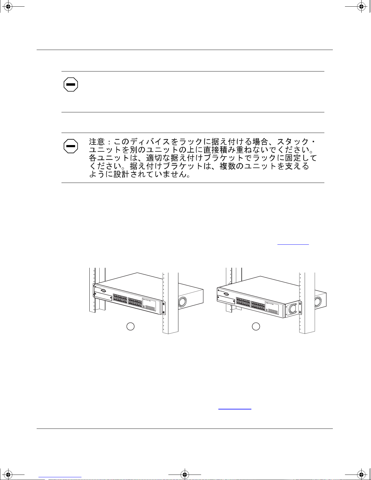
kombk.book Page 6 Thursday, February 18, 1999 10:59 AM
Using the BayStack 350 10/100/1000 Series Switch
Attenzione:
Se il dispositivo viene installato su una cremagliera, non
impilarlo su un altro dispositivo montato sulla cremagliera. Ciascuna unità
deve essere fissata alla cremagliera con le apposite staffe di montaggio. Tali
staffe non possono essere utilizzate per fissare più unità.
To install the BayStack 350 switch in a rack, follow these steps:
1.
Determine how far you want the switch to protrude in front of the rack.
You c an install the switch flush to the rack or extended from the rack,
depending on the orientation of the mounting brackets (see Figure 2-2
).
1
1 = Flush with rack
2 = Extended from rack
Figure 2-2. Positioning the Chassis in the Rack
2.
Using a Phillips screwdriver, attach a mounting bracket to each side of
the switch using the supplied screws (Figure 2-3
2
).
BS35035A
2-6
304376-B Rev 00
Page 99
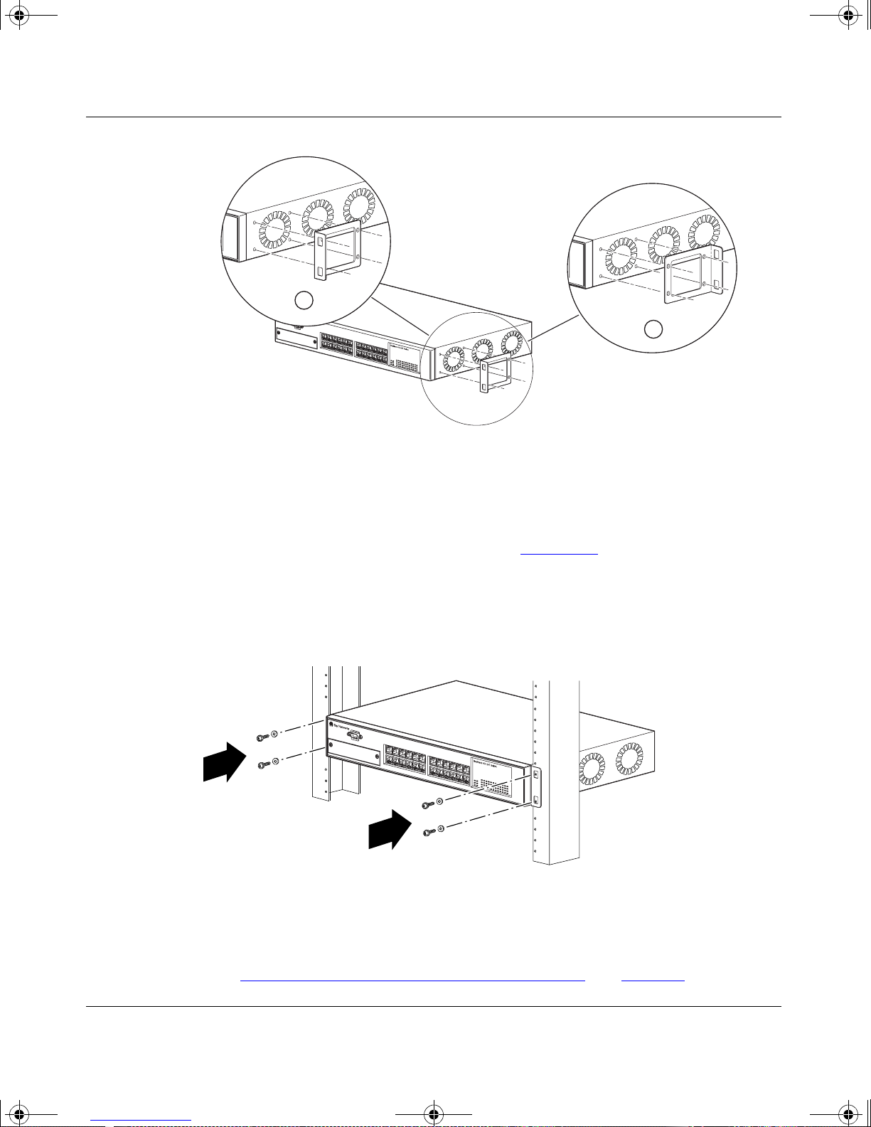
kombk.book Page 7 Thursday, February 18, 1999 10:59 AM
1
1 = Flush with rack
2 = Extended from rack
Installing the BayStack 350 Switc h
2
Figure 2-3. Attaching Mounting Brackets
3.
Position the switch in the rack and align the holes in the mo unting
bracket with the holes in the rack (see Figure 2-4
4.
Insert two screws, appropriate for your 19-inch rack, into each of the
).
mounting brackets and tighten.
BS35036A
Figure 2-4. Installing the BayStack 350 Switch in an Equipment Rack
5.
After the switch is secured in the rack, proceed to the next section,
“Attaching Devices to the BayStack 350 Switch
304376-B Rev 00
BS35037A
” on page 2-8.
2-7
Page 100

kombk.book Page 8 Thursday, February 18, 1999 10:59 AM
Using the BayStack 350 10/100/1000 Series Switch
Attaching Devices to the BayStack 350 Switch
This section descr ib es ho w t o atta ch devices to th e BayS tack 350 swit ch port s and
how to connect a cons ole ter minal to the switch Console/ Comm port. You can use
the console termi nal to ob serve the po wer o n se lf-t est r esu lts and set up the switc h,
if required, as described later in this chapter.
The BayStack 350 switch has an Uplink/Expansion slot that allows you to attach
optional media de pendent adapters (MDAs). The MDAs support a r ang e of media
types (see Appendi x B, “Media Dependent Adapters” for mo re inf or ma ti on a bout
MDA types available from Bay Networks). Refer to the documentation that came
with your specific MDA for information about its cabling and LED indications.
Depending on your network configuration requirements, connect the RJ-45 port
cables, the console port, and any optional MDA port cables. After attaching the
device s to the BaySta ck 350 swit ch, proceed to “
to connect the AC power cord and power up the switch.
Connecting Power ” on page 2-11
You can connect the BayStack 350 switch to any equipment that conforms to the
IEEE 802.3 standard, such as the following devices:
• Ethernet networking devices
• Individual workstations or serv ers
• Other switches, bridges, or hubs
For informat ion about au toneg otiat ion, see “Autosensing and Autone gotiat ion” on
page 1-13. For troubleshooting possible related problems, see “Autonegotiation
Modes” on page 4-6.
2-8
304376-B Rev 00
 Loading...