

Page 1

BayRS Version 13.10
Document Change
Notice
BayRS Version 13.10
Site Manager Software Version 7.10
BCC Version 4.10
Part No. 300020-C Rev. 00
November 1998
Page 2

4401 Great America P a rkw ay 8 Feder al S treet
Santa Clara, CA 95054 Billerica, MA 01821
Copyright © 1998 Bay Networks, Inc.
All rights reserved. Printed in the USA. November 1998.
The information in this document is subject to change without notice. The statements, configurations, technical data,
and recommendations in this document are believed to be accurate and reliable, but are presented without express or
implied warranty. Users must take full responsibility for their a pplic atio ns o f a ny products specif i ed in th is d ocume nt .
The information in this document is proprietary to Bay Networks, Inc.
The software described in this document is furnished under a license agreement and may only be used in accordance
with the terms of that license. A summary of the Software License is included in this document.
Tr ademarks
ACE, AFN, AN, BCN, BLN, BN, BNX, CN, FRE, LN, PPX, and Bay Networks are registered trademarks and
Advanced Remote Node, ANH, ARN, ASN, BayRS, BaySecure, BayStack, BayStream, BCC, BCNX, BLNX,, FN,
IPAutoLearn, SN, SPEX, Switch Node, System 5000, and the Bay Networks logo are trademarks of Bay Networks,
Inc.
Microsoft, MS, MS-DOS, Win32, Windows, and Windows NT are registered trad emarks of Microsoft C orporation.
All other trademarks and registered trademarks are the property of their respective owners.
Restricted Rights Legend
Use, duplication, or disclosure by the United States Government is subject to restrictions as set forth in subparagraph
(c)(1)(ii) of the Rights in Technical Data and Computer Software clause at DFARS 252.227-7013.
Notwithstanding any other license agreement that may pertain to, or accompany the delivery of, this computer
software, the rights of the United States Government regarding its use, reproduction, and disclosure are as set forth in
the Commercial Computer Software-Restricted Right s clause at FAR 52.227-19.
Statement of Conditions
In the interest of improving internal design, operational function, and/or reliability, Bay Networks, Inc. reserves the
right to make changes to the products described in this document withou t notice.
Bay Networks, Inc. does not assume any liability that may occur due to the use or application of the product(s) or
circuit layout(s) described herein.
Portions of the code in this software product may be Copyright © 1988, Regents of the University of California. All
rights reserved. Redistribution and use in source and binary forms of such portions are permitted, provided that the
above copyright notice and this paragraph are duplicated in all such forms and that any documentation, advertising
materials, and other materials related to such distribution and use ackno wledge that such portions o f the software were
developed by the University of California, Berkeley. The name of the University may not be used to endorse or
promote products derived from such portions of the software without specific prior written permission.
SUCH PORTIONS OF THE SOFTWARE ARE PROVIDED “AS IS” AND WITHOUT ANY EXPRESS OR
IMPLIED WARRANTIES, INCLUDING, WITHOUT LIMITATION, THE IMPLIED WARRANTIES OF
MERCHANTABILITY AND FITNESS FOR A PARTICULAR PURPOSE.
In addition, the program and information contained herein are licensed only pursuant to a license agreement that
contains restrict ions on use and disclosur e (that may incorp or ate by reference certa in limitations and notices imposed
by third parties).
ii
300020-C Rev. 00
Page 3

Bay Networks, Inc. Software License Agreement
NOTICE: Please carefully read this license agreement before copying or using the accompanying software or
installing the hardware unit with pre-enabled software (each of which is referred to as “Software” in this Agreement).
BY COPYING OR USING THE SOFTWARE, YOU ACCEPT ALL OF THE TERMS AND CONDITIONS OF
THIS LICENSE AGREEMENT. THE TERMS EXPRESSED IN THIS AGREEMENT ARE THE ONLY TERMS
UNDER WHICH BAY NETWORKS WILL PERMIT YOU TO USE THE SOFTWARE. If you do not accept these
terms and conditions, return the product, unused and in the original shipping container, within 30 days of purchase to
obtain a credit for the full purchase price.
1. License Grant. Bay Networks, Inc. (“Bay Networks”) grants the end user of the Software (“Licensee”) a personal,
nonexclusive, nontransferable license: a) to use the Software either on a single computer or, if applicable, on a single
authorized device identified by host ID, for which it was originally acquired; b) to copy the Software solely for backup
purposes in suppo rt of authorized use of the Software; and c) to use and copy the associat ed user manual solely in
support of authorized use of the Software by Licensee. This license applies to the Software only and does not extend
to Bay Networks Agent software or other Bay Networks software products. Bay Networks Agent software or other
Bay Networks software products are licensed for use under the terms of the applicable Bay Networks, Inc. Software
License Agreement that accompanies such software and upon payment by the end user of the applicabl e license fees
for such software.
2. Restrictions on use; reservation of rights. The Software and user manuals are protected under copyright laws.
Bay Networks and/o r its licensors retain all title and ownership in both the Software and user manuals, incl uding any
revisions made by Bay Networks or its licensors. The copyright notice must be reproduced and included with any
copy of any portion of the Software or user manuals. Licensee may not modify , translate, decompile, disassemble, use
for any competiti ve analysis, re v erse engineer , distribute, o r create deriv ati v e works from the Softw are or user manuals
or any copy, in whole or in part. Except as expressly p rovided in this Agreement, Licensee ma y not copy or transfer
the Software or user manuals, in whole or in part. The S of tware and user manuals embody Bay Networks’ and its
licensors’ confidential and proprietary intellectual property. Licensee shall not sublicense, assign, or otherwise
disclose to any third party the Software, or any information about the operation, design, performance, or
implementation of the Software and user manuals that is confidential to Bay Networks and its licensors; however,
Licensee may grant permission to its consultants, subcont ractors, and agents to us e the Software at Licensee’s facility,
provided they have agreed to use the Software only in accordance with the terms of this license.
3. Limited warranty. Bay Networks warrants each item of Software, as delivered by Bay Networks and properly
installed and operated on Bay Networks hardware or other equipment it is originally licensed for, to function
substantially as described in its accompanying user manual during its warranty period, which begins on the date
Software is first shipped to L icensee. If any i tem of Softwa re fails to so f unction during its w arranty period , as the sole
remedy Bay Networks will at its discretion provide a suitable fix, patch, or workaround for the problem that may be
included in a future Software release. Bay Netw ork s fur ther w arra nts to Licen see that the medi a on which the
Software is provide d will be free from de fects in materials a nd work manship un der normal u se for a period of 90 days
from the date Software is first shipped to Licensee. Bay Networks will replace defective media at no charge if it is
returned to Bay Ne twor ks during the warra nty per iod alon g with pro of of the da te of shipmen t. This wa rran ty does no t
apply if the media has been da maged a s a result of a ccident, m isuse, or ab u se. The Lic ensee a ssumes all responsib ility
for selection of the Software to achieve Licensee’s intended results and for the installation, use, and results obtained
from the Software. Bay Networks does not warrant a) that the functions contained in the software will meet the
Licensee’s requirements, b) that the Software will o pera te in the h ardware or software combinations that th e Licen see
may select, c) that the operation of the Softw a re will be uni nterru pte d or error free, or d) that all defec ts in the
operation of the Software will be corrected. Bay Networks is not obligated to remedy any Software defect that cannot
be reproduced with the latest Software release. These warranties do not apply to th e So ftw are if i t has been (i) altered,
except by Bay Netw orks o r in accorda nce with its instruction s; (ii) used in conjun ction with anoth er ve ndor’s product,
resulting in the defect; or (iii) damaged by improper environment, abuse, misuse, accident, or negligence. THE
FOREGOING WARRANTIES AND LIMITATIONS ARE EXCLUSIVE REMEDIES AND ARE IN LIEU OF ALL
OTHER WARRANTIES EXPRESS OR IMPLIED, INCLUDING W ITHOUT LIMITATION ANY WARRANTY OF
MERCHANTABILITY OR FITNESS FOR A PARTICULAR PURPOSE. Licensee is responsible for the security of
300020-C Rev. 00
iii
Page 4

its own data and information and for maintaining adequate procedures apart from the Software to reconstruct lost or
altered files, data, or programs.
4. Limitation of liability. IN NO EVENT WILL BAY NETWORKS OR ITS LICENSORS BE LIABLE FOR ANY
COST OF SUBSTITUTE PROCUREMENT; SPECIAL, INDIRECT, INCIDENTAL, OR CONSEQUENTIAL
DAMAGES; OR ANY DAMAGES RESULTING FROM INACCURATE OR LOST DATA OR LOSS OF USE OR
PROFITS ARISING OUT OF OR IN CONNECTION WITH THE PERFORMANCE OF THE SOFTWARE, EVEN
IF BAY NETWORKS HAS BEEN ADVISED OF THE POSSIBILITY OF SUCH DAMAGES. IN NO EVENT
SHALL THE LIABILITY OF BAY NETWORKS RELATING TO THE SOFTWARE OR THIS AGREEMENT
EXCEED THE PRICE PAID TO BAY NETWORKS FOR THE SOFTWARE LICENSE.
5. Government Licensees. This provision applies to all Software and documentation acquired directly or indirectly
by or on behalf of the United States Government. The Software and documentation are commercial products, licensed
on the open market at market prices, and were developed entirely at private expense and without the use of any U.S.
Government funds. The license to the U.S. Government is granted only with restricted rights, and use, duplication, or
disclosure by the U.S. Government is subject to the restrictions set forth in subparagraph (c)(1) of the Commercial
Computer Software––Restric ted Rig hts cla u se of FAR 52.227-19 and the limitations set o ut in thi s license for civilian
agencies, and su bparagraph (c)(1 )(ii) of the Rights in Technical Data and Computer Software clause of DFARS
252.227-7013, for agencies of the Department of Defense or their successors, whichever is applicable.
6. Use of Software in the European Community. This provision applies to all Software acquired for use within the
European Community. If Licensee uses the Software within a country in the European Community, the Software
Directive enacted by the Council of European Com munities Directive dated 14 May, 1991, will apply to the
examination of the Software to facilitate interoperability. Licensee agrees to notify Bay Networks of any such
intended examinati on of the Software and may procure support and assistance from Bay Networks.
7. Term and termination. This license is effective until terminated; however, all of the restrictions with respect to
Bay Networks’ copyright in the Software and user manuals will cease being effective at the date of expiration of the
Bay Networks copyright; those restrict ions relating to use and disclosure of Bay Networks’ confidential information
shall continue in effect. Licensee may terminate this license at any time. The license will automatically terminate if
Licensee fails to comply with any of the terms and conditions of the license. Upon termination for any reason,
Licensee will immediatel y destroy or return to Bay Networks the Software, user manuals, and all copies. Bay
Networks is not liable to Licensee for damages in any form solely by reason of the termination of this license.
8. Export and Re-export. Licensee agrees not to export, directly or indirectly, the Software or related technical dat a
or information without first obtaining any required export licenses or other governmental approvals. Without limiting
the foregoing, Licensee, on behalf of itself and its subsidiaries and affiliates, agrees that it will not, without first
obtaining all export licenses and approvals required by the U.S. Government: (i) export, re-export, transfer, or divert
any such Software or tech nical data, or any direct product thereof, to any country to which su ch ex ports or re-exports
are restricte d or em b argoed under Un ite d Sta te s e x po r t con t rol laws and re gu la tions, or to any nati on al or resident of
such restricted or embargoed countries; or (ii) provide the Software or related technical data or information to any
military end user or for any military end use, including the design, development, or production of any chemical,
nuclear, or biological weapons.
9. General. If any provision of this Agreement is held to be invalid or unenforceable by a court of competent
jurisdiction, the remainder of the provisions of this Agreement shall remain in full force and effect. This Agreement
will be governed by the laws of the state of California.
Should you have any questions concerning this Agreement, contact Bay Networks, Inc., 4401 Great America Parkway,
P. O. Box 58185, Santa C lara, California 95 054-8185.
LICENSEE ACKNOWLEDGES THAT LICENSEE HAS READ THIS AGREEMENT, UNDERSTANDS IT, AND
AGREES TO BE BOUND BY ITS TERMS AND CONDITIONS. LICENSEE FURTHER AGREES THAT THIS
AGREEMENT IS THE ENTIRE AND EXCLUSIVE AGREEMENT BETWEEN BAY NETWORKS AND
LICENSEE, WHICH SUPERSEDES ALL PRIOR ORAL AND WRITTEN AGREEMENTS AND
COMMUNICATIONS BETWEEN THE PARTIES PERTAINING TO THE SUBJECT MATTER OF THIS
AGREEMENT. NO DIFFERENT OR ADDITIONAL TERMS WILL BE ENFORCEABLE AGAINST BAY
NETWORKS UNLESS BAY NETWORKS GIVES ITS EXPRESS WRITTEN CONSENT, INCLUDING AN
EXPRESS WAIVER OF THE TERMS OF THIS AGREEMENT.
iv
300020-C Rev. 00
Page 5

Contents
Preface
Text Conventions .............................................................................................................. xi
Acronyms ........................... .......................... .......................... ......................... .................xi ii
Bay Networks Technical Publications ..............................................................................xiii
How to Get Help ..............................................................................................................xiv
Document Change Notice
Configuring L2TP Services ................................................................................................4
Overview of the Name Server Addresses Feature ......................................................4
Specifying the Origin of the Name Server Address ....................................................6
Configuring the NSA Feature for L2TP .....................................................................10
Checking NSA Assignments .....................................................................................11
Name Server Addresses Parameter Descriptions ....................................................14
Cable Guide .......... ...... ....... ...... ....... ...... ....... ...... ....... ...... ....... ...................................... ....1 6
50-Pin to V.28 Cable (Order No. AA0018023) ...........................................................17
15-Pin D-Sub to RS-232: Raise DTR (Order No. 7118) ............................................18
15-Pin D-Sub to RS-232: V.25bis (Order No. 7119) ..................................................19
15-Pin D-Sub to V.35: V.25bis (Order No. 7120) .......................................................20
15-Pin D-Sub to V.35: Raise DTR (Order No. 7121) .................................................21
44-Pin D-Sub to V.35: Raise DTR (Order No. 7137) .................................................22
44-Pin D-Sub to RS-232: Raise DTR (Order No. 7138) ............................................24
44-Pin to V.35M (Order No. 7159) .............................................................................26
RS-232 Pass-Through: 15-Pin to RS-232 (Order No. 7218) .....................................28
44-Pin D-Sub to V.35: Leased Line or V.25bis (Order No. 7220) ..............................29
15-Pin D-Sub to RS-232 (Order No. 7255) ...............................................................31
15-Pin D-Sub to V.28 (Order No. 7256) .....................................................................32
44-Pin D-Sub to RS-232: Leased Line or V.25bis (Order No. 7826) .........................33
RS-232 Pass-Through: 44-Pin to RS-232 (Order No. 7833) .....................................34
V.35 Pass-Through: 44-Pin to V.35 (Order No. 7834) ................................................35
300020-C Rev. 00
v
Page 6

44-Pin D-Sub to V.28 (Order No. 7837) .....................................................................37
50-Pin to V.35 (Order No. 7932) ................................................................................39
50-Pin to V.35: Raise DTR (Order No. 7933) ............................................................41
50-Pin to RS-232 (Order No. 7934) ..........................................................................43
50-Pin to RS-232: Raise DTR (Order No. 7935) .......................................................44
15-Pin to F RS-232 Synchronous Pass-Through (Order No. 7941) ..........................45
44-Pin to F RS-232 Synchronous Pass-Through (Order No. 7943) ..........................46
44-Pin to F V.35 Synchronous Pass-Through (Order No. 7944) ...............................47
50-Pin to F RS-232 Synchronous Pass-Through (Order No. 7945) ..........................48
50-Pin to F V.35 Synchronous Pass-Through (Order No. 7946) ...............................49
Configuring PPP Services ...............................................................................................50
Setting the Maximum Receive Unit (MRU) ................................................................50
Disabling RFC 1661 Compliance ..............................................................................52
PPP Line Parameters ............... ...... ....... ...... ....... ...... ....... ...... ...... ....... ...... .................53
Configuring Data Encryption Services .............................................................................55
Using Encryption with Dial Services .........................................................................55
Configuring Frame Relay Services ..................................................................................56
Calculating the MTU Size for Frame Relay Connections ..........................................56
Using Technician Interface Software ...............................................................................57
Monitoring EIA Signals ..............................................................................................57
Configuring and Managing Routers with Site Manager ...................................................58
Configuring and Monitoring Syslog Using the BCC ..................................................58
Upgrading Routers to BayRS Version 13.xx ....................................................................89
Boot and Diagnostic PROM Upgrades for Version 13.10 ..........................................89
vi
300020-C Re v. 00
Page 7

Figures
Figure 1. Specifying Server-Assigned NSAs in the Dial-Up Networking
TCP/IP Settings Window .............................................................................5
Figure 2. Network with Name Server Address Origin Parameter Set to Local ...........8
Figure 3. Network with Name Server Address Origin Parameter Set to RADIUS ......9
Figure 4. Run Window ..............................................................................................11
Figure 5. IP Configuration Window ..........................................................................12
Figure 6. More Info. IP Configuration Window ..........................................................13
Figure 7. Syslog and
Figure 8. Router Event Message Filtering for One Host ..........................................61
Figure 9. Syslog Message Encapsulation ................................................................65
Figure 10. Syslog Message Composition ...................................................................66
Figure 11. BCC Configuration Hierarchy for Syslog Services ....................................70
syslogd
Operations ......... ...... ....... ...... ....................................59
300020-C Rev. 00
vii
Page 8

Page 9

Tables
Table 1. Version 13.10/7.10 Documentation ............................................................1
Table 2. Syslog Parameters (box or stack > syslog) ...............................................86
Table 3. Parameters of log-host (box or stack > syslog > log-host) .......................86
Table 4. Parameters of filter (box or stack > syslog > log-host > filter) ..................87
Table 5. Version 13.10 Boot and Diagnostic PROM Revisions ...............................89
300020-C Rev. 00
ix
Page 10

Page 11

This guide describes changes to router software and hardware documentation
since BayRS
Version 13.10, identifies new and revised manuals since Version 13.00, and lists
those manuals that we have not revised and which are affected by sections in this
document change notice.
Text Conventions
Preface
™
Version 13.00. Table 1 of this guide li sts the manuals in cluded with
This guide uses the following text conventions:
angle brackets (< >) Indicate that you choose the text to enter based on the
description inside the brackets. Do not type the
brackets when entering the command.
Example: If the command syntax is:
ping
bold text
ip_address
<
ping 192.32.10.12
Indicates command names and options and text that
, you enter:
>
you need to enter.
Example: Enter
Example: Use the
show ip {alerts | routes
dinfo
command.
}.
300020-C Rev. 00
xi
Page 12

BayRS Version 13.10 Document Change Notice
braces ({}) Indicate required elements in syntax descriptions
where there is more than one option. You must choose
only one of the options. Do not type the braces when
entering the command.
Example: If the command syntax is:
show ip {alerts | routes}, you must enter either:
show ip alerts or show ip routes, but not both.
brackets ([ ]) Indicate optional elements in syntax descriptions. Do
not type the brackets when entering the command.
Example: If the command syntax is:
show ip interfaces [-alerts], you can enter either:
show ip interfaces or show ip interfaces -alerts
ellipsis points (. . . ) Indicate that you repeat the last element of the
command as needed.
Example: If the command syntax is:
ethernet/2/1 [<
ethernet/2/1 and as many parameter-value pairs as
needed.
parameter> <value
.
>] . . . , you enter
xii
italic text Indicates file and directory names, new terms, book
titles, and variables in command syntax descriptions.
Where a variable is two or more words, th e words are
connected by an underscore.
Example: If the command syntax is:
show at <
valid_route
valid_route
>
is one variable and you substitute one value
for it.
screen text Indicates system output, for example, prompts and
system m essages.
Example:
Set Bay Networks Trap Monitor Filters
300020-C Re v. 00
Page 13

Preface
separator ( > ) Shows menu paths.
Example: Protocols > I P identifies the IP option on the
Protocols menu.
Acrony ms
vertical line (
) Separates choices for command keywords and
|
arguments. Enter only one of the choices. Do not type
the vertical line when entering the command.
Example: If the command syntax is:
show ip {alerts | routes
show ip alerts
show ip routes
or
This guide uses the following acronyms:
DNS domain name server
IP Internet Protocol
L2TP Layer 2 Tunneling Protocol
NSA name server address
MRU maximum receive unit
MTU maximum transmissio n unit
}
, you enter either:
, but not both.
OSPF Open Shortest Path First
PPP Point-to-Point Protocol
SNMP Simple Network Management Protocol
Bay Networks Technical Publications
You can now print Bay Networks technical manuals and release notes free,
directly from the Internet. Go to support.baynetwork s.com/libr a ry/tpubs/ . Fi nd the
Bay Networks
specific category and model or version for your hardware or software product.
300020-C Rev. 00
®
product for which you need documentation. Then locate the
xiii
Page 14

BayRS Version 13.10 Document Change Notice
Using Adobe Acrobat Reader, you can op en the manuals and r eleas e note s, sea rch
for the sections you need, and print them on most standard printers. You can
download Acrobat Reader free from the Adobe Systems Web site,
www.adobe.com.
You can purchase Bay Networks documentation sets, CDs, and selected technical
publications through the Bay Networks Collateral Catalog. The catalog is located
on the World Wide Web at support.baynetworks.com/catalog.html and is divided
into sections arranged alphabetically:
• The “CD ROMs” section lists available CDs.
• The “Guides/Books” section lists books on technical topics.
• The “Technical Manuals” section lists available printed documentation sets.
Make a note of the part numbers and prices of the items that you want to order.
Use the “Marketing Collateral Catalog description” link to place an order and to
print the order form.
How to Get Help
For product as si st ance, support contracts , inf or ma ti on abo u t edu cat ional services,
and the telephone numbers of our global supp ort office s, go to the following URL:
http://www.baynetworks.com/corporate/ conta cts/
In the United States and Canada, you can dial 800-2LANWAN for assistance.
xiv
300020-C Re v. 00
Page 15

Document Change Notice
Table 1 lists the manuals included in the Version 13.10/7.10 release and those
manuals affected by sections in this document.
Table 1. Version 13.10/7.10 Documentation
Revised Book
Document Title
BCC Quick Reference
Cable Guide ✔
Configuring and Managing Routers with
Site Manager
Configuring and Troubleshooting Bay Dial
VPN Networks
Configuring AppleTal k Services
Configuring APPN Services
Configuring ATM DXI Services
Configuring ATM Half-Bridge Services
Configuring ATM and MPLS Services ✔
Configuring BaySecure FireWall-1 ✔
Configuring BayStack Remote Access
Configuring Bridging Services
Configuring BSC Transport Services
for 13.10/7.10
✔
Affected by
Section in DCN
✔
Configuring Data Compression Services ✔
Configuring Data Encryption Services ✔
Configuring DECnet Services
300020-C Rev. 00
(continued)
1
Page 16

BayRS Version 13.10 Document Change Notice
Table 1. Version 13.10/7.10 Documentation
Revised Book
Document Title
Configuring Dial Services
Configuring DLSw Services
Configuring Ethernet, FDDI, and Token
Ring Services
Configuring Frame Relay Services
Configuring IP Security Services
Configuring Interface and Router
Redundancy
Configuring IP M ul tic as ting a nd Multimedia
Services
Configuring IP Services
Configuring IP Utilities
Configuring IPv6 Services
Configuring IPX Services
for 13.10/7.10
✔
✔
✔
✔
✔
✔
✔
(continued)
Affected by
Section in DCN
✔
Configuring L2TP Services
Configuring LLC Services
Configuring LNM Services
Configuring OSI Services
Configuring Polled AOT Transport Services
Configuring PPP Services
Configuring RADIUS
Configuring RMON and RMON2
Configuring SDLC Services
Configuring SMDS
Configuring SNMP, BootP, DHCP, and
RARP Services
Configuring Traffic Filters and Protocol
Prioritization
Configuring VINES Services
Configuring Virtual Router Redundancy
Services
✔
✔
✔
✔
2
(continued)
300020-C Re v. 00
Page 17

Document Change Notice
Table 1. Version 13.10/7.10 Documentation
Revised Book
Document Title
Configuring WAN Line Services
Configuring X.25 Gateway Services
Configuring X.25 Services
Configuring XNS Services
Connecting ASN Routers to a Network
Managing Routers Using the HTTP Server
Quick-Starting Ro uters
Troubleshooting Routers
Upgrading Routers to BayRS Version 13.xx
Using Technician Interface Scripts
Using Technician Interface Software
Using the Bay Command Console
Writing Technician Interface Scripts
for 13.10/7.10
✔
✔
✔
(continued)
Affected by
Section in DCN
✔
✔
300020-C Rev. 00
3
Page 18

BayRS Version 13.10 Document Change Notice
Configuring L2TP Services
The following sections are amendments to Configuring L2TP Services.
Overview of the Name Server Addresses Feature
Bay Networks® has implemented RFC 1877, “IP Control Protocol (IPCP) Name
Server Addresses,” for Layer 2 Tunneling Protocol (L2TP) connections. This
name server address (NSA) feature enables a remote host dialing in to a Bay
Networks router acting as an L2TP network server (LNS) to obtain NSAs from
either the LNS or a RADIUS server.
T o use th e NSA feature, users at remot e sites confi guring their dial-up conn ections
in Windows
connections will use server-assigned name server addresses, indicating that a
remote server provides NSAs. Users specify this in the Dial-Up Networking
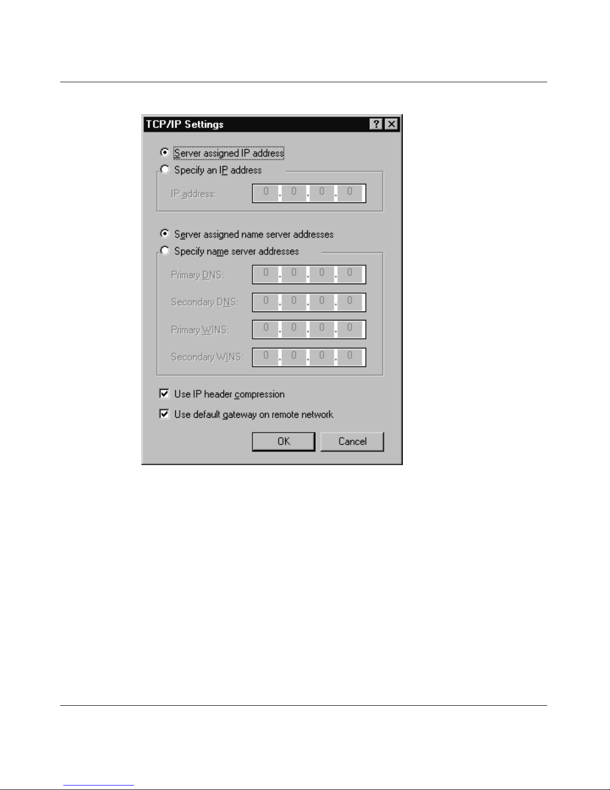
TCP/IP Settings window for the connection (Figure 1)
®
95, Windows 98, or Windows NT® must specify that their
.
If a user does not select the server-assigned name server addresses setting, the
connection uses t he NSAs tha t the user en ters in the TCP/IP Set ting s window, and
the connection does not use the NSA feature.
4
300020-C Re v. 00
Page 19
Document Change Notice
300020-C Rev. 00
Figure 1. Specifying Server-Assigned NSAs in the Dial-Up Networking
TCP/IP Settings Window
When users specify that they want to use server-assigned NSAs, they should not
enter primary and secondary domain name server (DNS) and WINS name server
addresses (also called NetBIOS name server addresses or NBNS addresses).
Instead, when a user dials in, the LNS or RADIUS server automatically assigns
name server addresses for the connection. If a name server address changes, the
network administrator can make a single modification at the LNS or RADIUS
server site; every remote user is not required to go back into the TCP/IP Settings
window and enter a new address.
5
Page 20

BayRS Version 13.10 Document Change Notice
Specifying the Origin of the Name Server Address
When you configure t he NSA feature on the route r, you must us e Site Manager to
set the Name Server Address Origin parameter to one of three values: Disable,
Local, or RADIUS. The following sections describe each of these options.
Disable
If you leave the Name Server Address O rigin parameter at its defa ult of Disabl e,
the NSA feature is disa bled for the LNS c onfigure d on this router s lot. Wh en users
dial in from a remote location, the connection uses DNS and NBNS (WINS)
addresses that the users enter in the Dial-Up Networking TCP/IP Settings
windows on their PCs.
Local
If you set the Name Server Address Origin parameter to Local, users who dial in
to the LNS configure d on th is sl ot, provid ed that they have con figur ed the TCP/IP
settings as server-assigned name server addresses, use the DNS and NetBIOS
NSAs that you set in Site Manager. You set these addresses via the Site Manager
parameters Primary DNS Address, Secondary DNS Address, Primary NBNS
Address, and Secondary NBNS Address.
RADIUS
If you set the Name Server Address Origin parameter to RADIUS, users who dial
in to the LNS on t his s lot obtain NSAs from a RADIUS server, provided that the y
have configured their TCP/IP settings as server-assigned name server addresses.
Specifying the origin as RADIUS allows a finer distinction among users than is
possible with a Local origin setti ng. Through the RADIUS server, you can speci fy
that certain users use particular NSAs and other users use other NSAs, even if all
users dial in through the same LNS.
To use a RADIUS server as the Name Server Address Origin, your configuration
must meet the following requirements:
• You must have entered valid values for these three L2TP Site Manager
parameters: RADIUS Primary Server IP Address; RADIUS Primary Server
Password; and RADIUS Client IP Address.
• The RADIUS server must be operational at the location you specified.
6
300020-C Re v. 00
Page 21

Document Change Notice
• The RADIUS server must have entries in its database corresponding to
incoming host user names.
• The RADIUS server must support vendor specific attributes (VSA) and must
have the following entries in its dictionary:
ATTRIBUTE Annex-Primary-DNS-Server Bay-VSA(54 , ipadd r)
ATTRIBUTE Annex-Secondary-DNS-Server Bay-VSA(55, ipaddr)
ATTRIBUTE Annex-Primary-NBNS-Server Bay-VSA(56, ipaddr)
ATTRIBUTE Annex-Secondary-NBNS-Server Bay-VSA(57, ipadd r)
Examples
Name Server Address Origin Parameter Set to Local
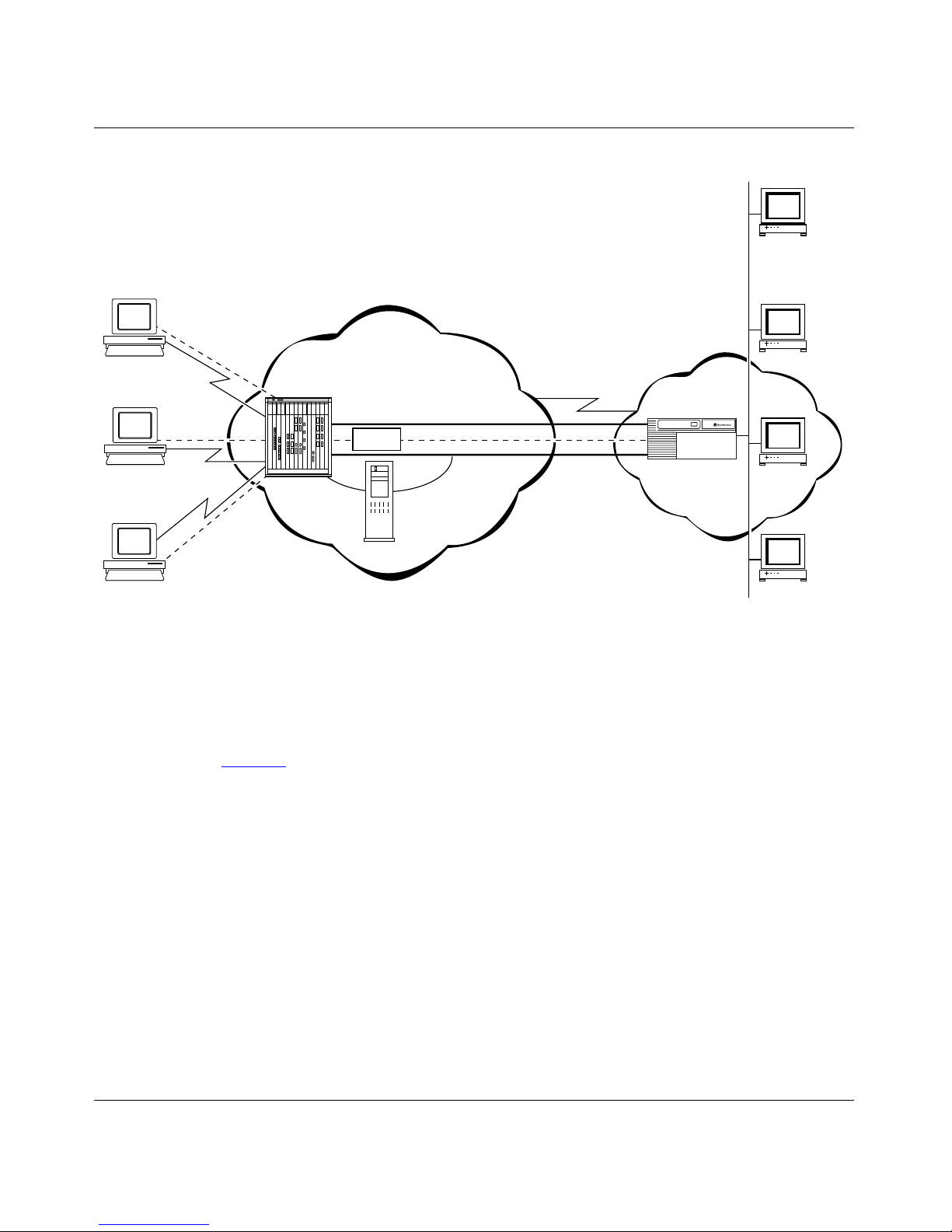
Figure 2 shows a network with the following configuration:
• Users at remote hosts A, B, and C have specified “Server assigned name
server addresses” in the Dial-Up Networking TCP/IP Settings window on
their PCs.
• The Name Serv er Add ress Ori gin pa rameter i s se t to Loca l in Si te Mana ger on
the LNS at the corporate site.
• The other Site Manager parameters related to this NSA feature on the LNS
(Primary DNS Address, Secondary DNS Address, Primary NBNS Address,
and Secondary NBNS Address) are set to the addresses of name serv ers on the
corporate network (DNS1, DNS2, NBNS1, and NBNS2).
When users at remot e hosts A, B, and C mak e dial-u p connecti ons to the corporate
network, those connections use DNS1, DNS2, NBNS1, and NBNS2 as primary
and secondary name servers.
300020-C Rev. 00
7
Page 22
BayRS Version 13.10 Document Change Notice
Remote
host A
PC
DNS 1
Remote
host B
PC
Remote
host C
PC
ISP network
LAC
TMS
Corporate
network
LNS
Figure 2. Network with Name Server Address Origin Parameter Set to Local
Name Server Address Origin Parameter Set to RADIUS
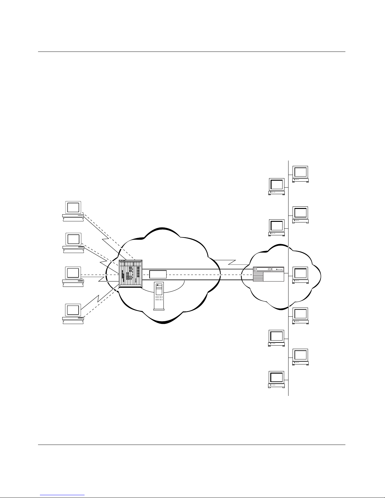
Figure 3 shows a network with the following configuration:
• Users at remote hosts Eng. host A, Eng. host B, Fin. host C, and Fin. host D
have specified “Server assigned name server addresses” in the Dial-Up
Networking TCP/IP Settings window on their PCs.
DNS 2
NBNS 1
NBNS 2
L2T0010A
• The Name Server Address Origin parameter is set to RADIUS in Site
Manager on the LNS at the corporate site.
• The RADIUS server on the corporate network specifies that users dialing in
from remote hosts in Engineering should use Eng. DNS1, Eng. DNS2,
Eng. NBNS1, and Eng. NBNS2 as their primary and secondary name servers.
• The RADIUS server on the corporate network specifies that users dialing in
from remote hosts in Finance shoul d use Fin. DNS1, Fin. DNS2, Fin. NBNS1,
and Fin. NBNS2 as their primary and secondary name servers.
8
300020-C Re v. 00
Page 23
Document Change Notice
When users at remote hosts Eng. host A and Eng. host B make dial-up
connections to the corporate network, those connections use Eng. DNS1,
Eng. DNS2, Eng. NBNS1, and Eng. NBNS2 as primary and secondary name
servers.
When users at remote hosts Fin. host A and Fin. host B make dial-up connections
to the corporate network, those connections use Fin. DNS1, Fin. DNS2,
Fin. NBNS1, and Fin. NBNS2 as primary and secondary name servers.
Eng. DNS 1
Eng.
host A
PC
Eng. DNS 2
Eng.
host B
PC
Fin.
host A
PC
Fin.
host B
PC
LAC
ISP network
TMS
Eng. NBNS 2
Corporate
network
LNS
Fin. DNS 2
Fin.NBNS 2
Eng. NBNS 1
RADIUS
server
Fin. DNS 1
Fin. NBNS 1
L2T0011A
Figure 3. Network with Name Server Address Origin Parameter Set to RADIUS
300020-C Rev. 00
9
Page 24

BayRS Version 13.10 Document Change Notice
Configuring the NSA Feature for L2TP
To configure the NSA feature for L2TP, complete the following tasks:
Site Manager Procedure
You do this System responds
1. In the Configuration Manager window,
choose
2. Choose IP. The IP menu opens.
3. Choose
4. Choose
5. Set the
parameter.
If you set this parameter to Local, you
must also set the following parameters:
• Primary DN S A ddress
• Secondary DNS Address
• Primary NBNS Address
• Secondary NBNS Address
If you set this parameter to Radius, you
must also set the following parameters:
• RADIUS Primary Server IP Address
• RADIUS Primary Server Password
• RADIUS Client IP Address
Protocols
L2TP
L2TP Configuration
Name Server Address Origin
.
. The L2TP menu opens.
. The L2TP Configuration List window
The Protocols menu opens.
opens.
Click on
descriptions beginning on page -14
6. Click on
Help
Done
10
or see the parameter
.
. You return to the Configuration Manager
window.
300020-C Re v. 00
Page 25
Checking NSA Assignments
To see which NSAs the LNS or RADIUS server assigned to a particular user,
complete the following steps at the remote user’s PC:
1.
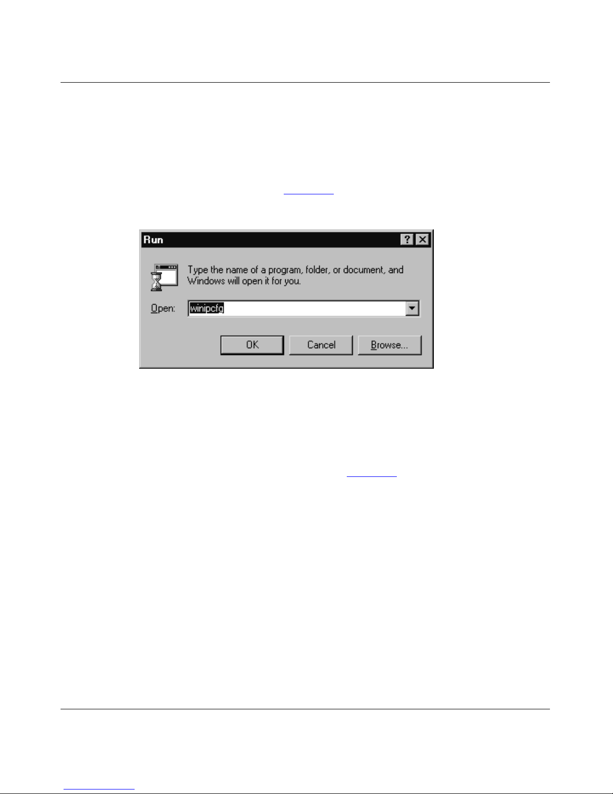
Choose Start > Run.
Document Change Notice
The Run window opens (Figure 4)
Figure 4. Run Window
2.
t the
A
winipcfg
Open:
prompt, enter:
.
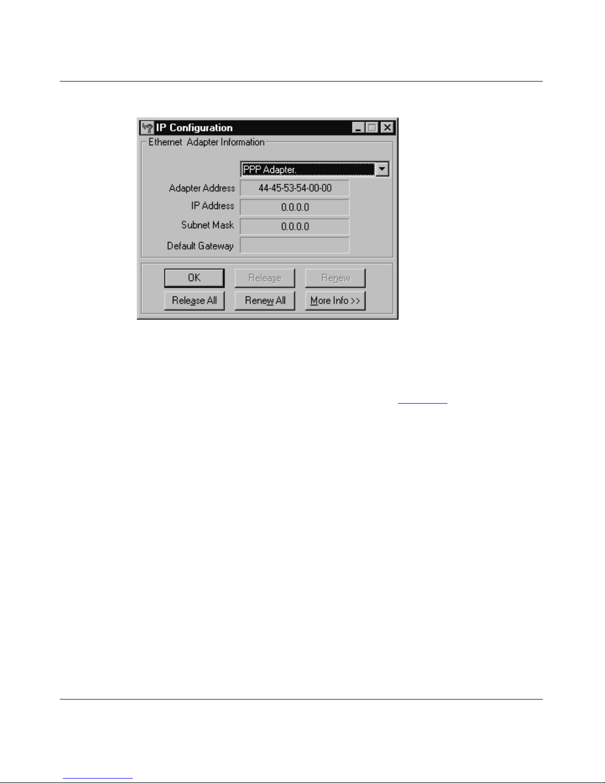
The IP Configuration window opens (Figure 5).
300020-C Rev. 00
11
Page 26
BayRS Version 13.10 Document Change Notice
Figure 5. IP Configuration Window
3.
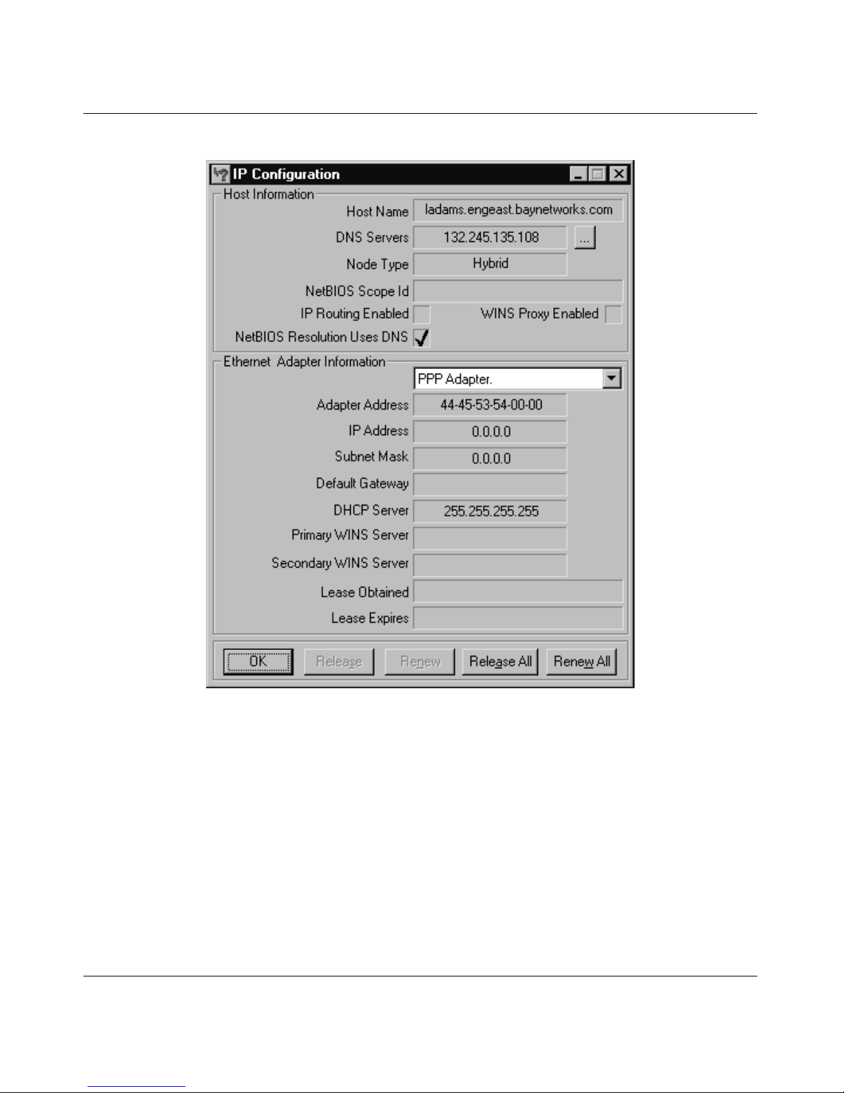
Click on More Info.
The More Info. IP Configuration window opens (Figure 6)
. The DNS Servers
field lists the primary and secondary DNS server addresses assigned by the
server. (Click on the
... button to see the secondary server address.) The
Primary WINS Serv er a nd Secondar y WINS Se rv er f ie lds lis t the pri mary and
secondary NBNS addresses, if any.
12
300020-C Re v. 00
Page 27
Document Change Notice
Figure 6. More Info. IP Configuration Window
300020-C Rev. 00
13
Page 28

BayRS Version 13.10 Document Change Notice
Name Server Addresses Parameter Descriptions
This section includes descriptions of the Site Manager parameters related to the
NSA feature. This is the same information available by clicking on the Help
button.
Parameter: Name Server Address Origin
Path: Configuration Manager > Protocols > IP > L2TP > L2TP Configuration
Default: Disable
Options: Disable
Function: Specifies whether or not the NSA feature is enabled and, if enabled, specifies
the source of the domain name server (DNS) and NetBIOS name server
(NBNS) addresses.
Instructions: Set to Disable if you do not want to use the NSA feature. If this feature is
disabled, remote hosts use the DNS and NBNS addresses configured on their
individual dial-up connections. Set to Local if you want all remote hosts to use
the DNS and NBNS addresses that you configure in Site Manager. Set to
RADIUS if you want remote hosts to obtain DNS and NBNS addresses from a
RADIUS server.
MIB Object ID: 1.3.6.1.4.1.18.3.5.23.2.1.23
|
Local | RADIUS
Parameter: Primary DNS Address
Path: Configuration Manager > Protocols > IP > L2TP > L2TP Configuration
Default: None
Options: Any valid IP address
Function: If the Name Server Addre ss Origin par ameter is set to Local, the Primary DNS
Address parameter specifies the address of the primary domain name server
(DNS) that every remote host should use.
Instructions: Enter the IP address of the primary DNS.
MIB Object ID: 1.3.6.1.4.1.18.3.5.23.2.1.24
14
300020-C Re v. 00
Page 29

Parameter: Secondary DNS Address
Path: Configuration Manager > Protocols > IP > L2TP > L2TP Configuration
Default: None
Options: Any valid IP address
Function: If the Name Server Addre ss Origin par ameter is set to Local, the Se condary
DNS Address parameter specifies the address of the secondary domain name
server (DNS) that every re mote host shou ld use. The syst em uses this secondary
DNS if it ca nnot reach the primary D NS.
Instructions: Enter the IP address of the secondary DNS.
MIB Object ID: 1.3.6.1.4.1.18.3.5.23.2.1.25
Parameter: Primary NBNS Address
Document Change Notice
Path: Configuration Manager > Protocols > IP > L2TP > L2TP Configuration
Default: None
Options: Any valid IP address
Function: If the Name Server Address Or igin paramet er is set to Local, the Prima ry NBNS
Address parameter specifies the address of the primary NetBIOS name server
(NBNS) that every remote host should use.
Instructions: Enter the IP address of the primary NBNS.
MIB Object ID: 1.3.6.1.4.1.18.3.5.23.2.1.26
Parameter: Secondary NBNS Address
Path: Configuration Manager > Protocols > IP > L2TP > L2TP Configuration
Default: None
Options: Any valid IP address
Function: If the Name Server Addre ss Origin par ameter is set to Local, the Se condary
NBNS Address parameter speci fies the addr ess of the seconda ry NetBIOS name
server (NBNS) that every remote host should use. The system uses this
secondary NBNS if it cannot reach the primary NBNS.
Instructions: Enter the IP address of the secondary NBNS.
MIB Object ID:
1.3.6.1.4.1.18.3.5.23.2.1.27
300020-C Rev. 00
15
Page 30

BayRS Version 13.10 Document Change Notice
Cable Guide
The following sections are amendments to the Cable Guide:
• 50-Pin to V.28 Cable (Order No. AA0018023)
• 15-Pin D-Sub to RS-232: Raise DTR (Order No. 7118)
• 15-Pin D-Sub to RS-232: V.25bis (Order No. 7119)
• 15-Pin D-Sub to V.35: V.25bis (Order No. 7120)
• 15-Pin D-Sub to V.35: Raise DTR (Order No. 7121)
• 44-Pin D-Sub to V.35: Raise DTR (Order No. 7137)
• 44-Pin D-Sub to RS-232: Raise DTR (Order No. 7138)
• 44-Pin to V.35M (Order No. 7159)
• RS-232 Pass-Through: 15-Pin to RS-232 (Order No. 7218)
• 44-Pin D-Sub to V.35: Leased Line or V.25bis (Order No. 7220)
• 15-Pin D-Sub to RS-232 (Order No. 7255)
• 15-Pin D-Sub to V.28 (Order No. 7256)
• 44-Pin D-Sub to RS-232: Leased Line or V.25bis (Order No. 7826)
• RS-232 Pass-Through: 44-Pin to RS-232 (Order No. 7833)
• V.35 Pass-Through: 44-Pin to V.35 (Order No. 7834)
• 44-Pin D-Sub to V.28 (Order No. 7837)
• 50-Pin to V.35 (Order No. 7932)
• 50-Pin to V.35: Raise DTR (Order No. 7933)
• 50-Pin to RS-232 (Order No. 7934)
• 50-Pin to RS-232: Raise DTR (Order No. 7935)
• 15-Pin to F RS-232 Synchronous Pass-Through (Order No. 7941)
• 44-Pin to F RS-232 Synchronous Pass-Through (Order No. 7943)
• 44-Pin to F V.35 Synchronous Pass-Through (Order No. 7944)
• 50-Pin to F RS-232 Synchronous Pass-Through (Order No. 7945)
• 50-Pin to F V.35 Synchronous Pass-Through (Order No. 7946)
16
300020-C Re v. 00
Page 31
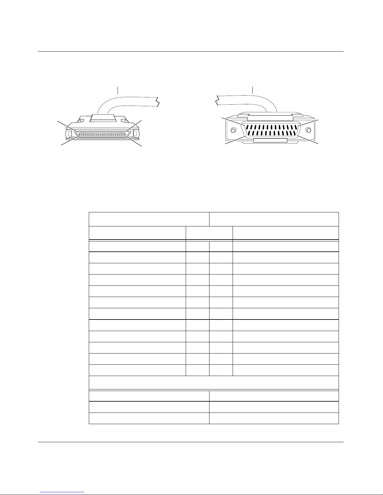
50-Pin to V.28 Cable (Order No. AA0018023)
(4.57 m)
Document Change Notice
Pin 1
Pin 26
50-position 0.8-mm plug
(ground shield connected to internal shell)
Pin 25
Pin 50
Industry Interface Type: V.28 (V.10)
Bay Networks Termination Remote Termination
Signal Pin # to Pin # Signal
Fr a me Groun d 1 1 Fr am e Gro und
Send Data + 2 2 Send Data
Receive Data + 3 3 Receive Data
Request to Send + 4 4 Request to Send
Clear to Send + 5 5 Clear to Send
Pin 1
Pin 14
25-position D-sub plug with M-3 jack screws
(ground shield connected to backshell)
Pin 13
Pin 25
CAB0103A
300020-C Rev. 00
Data Set Ready + 6 6 Data Set Ready
Signal Ground 7 7 Signal Ground
Data Terminal Ready + 8 20 Data Terminal Ready
Data Carrier Detect + 9 8 Data Carrier Detect
Send Timing + 10 15 Send Timing
Receive Timing + 11 17 Receive Timing
Terminal Timing + 12 24 Terminal Timing
Internal Wire Connections
Pin 7 > 30 > 31
Pin 13 > 38
Pin 14 > 39
17
Page 32
BayRS Version 13.10 Document Change Notice
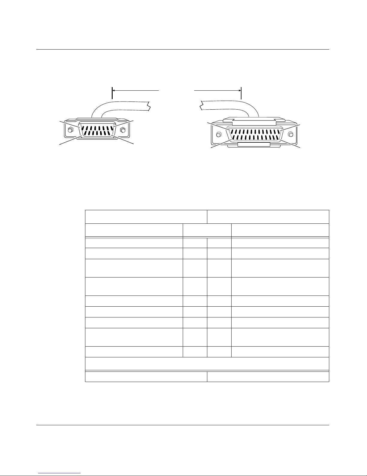
15-Pin D-Sub to RS-232: Raise DTR (Order No. 7118)
15 ft
(4.57 m)
Pin 1
Pin 8
P
Pin 1
Pin 13
Pin 9
15-position D-sub plug with locking posts
(ground shield connected to backshell)
Industry Interface Type: RS-232-C
Bay Networks Termination Remote Termination
Signal Pin # to Pin # Signal
Signal Ground 1 7 Signal Ground
Transmitted Data 2 2 Transmitted Data
Transmitter Signal Element Timing
(DTE Source)
Transmitter Signal Element Timing
(DCE Source)
Request to Send 6 4 Request to Send
Clear to Send 8 6 Data Set Ready
Pin 15
Pin 14
25-position D-sub plug with screw locks
(ground shield connected to backshell)
Pin 25
CAB0005A
3 24 Transmitter Signal Element Timing
(DTE Source)
4 15 Transmitter Signal Element Timing
(DCE Source)
Data Carrier Detect 10 22 Ring Indicator
Receiver Signal Element Timing
(DCE Source)
Received Data 14 3 Received Data
Internal Wire Connections
Pin 1 > 7Pin 4 >
18
12 17 Receiver Signal Elem ent Timing
(DCE Source)
20 (Data Terminal Ready)
300020-C Re v. 00
Page 33
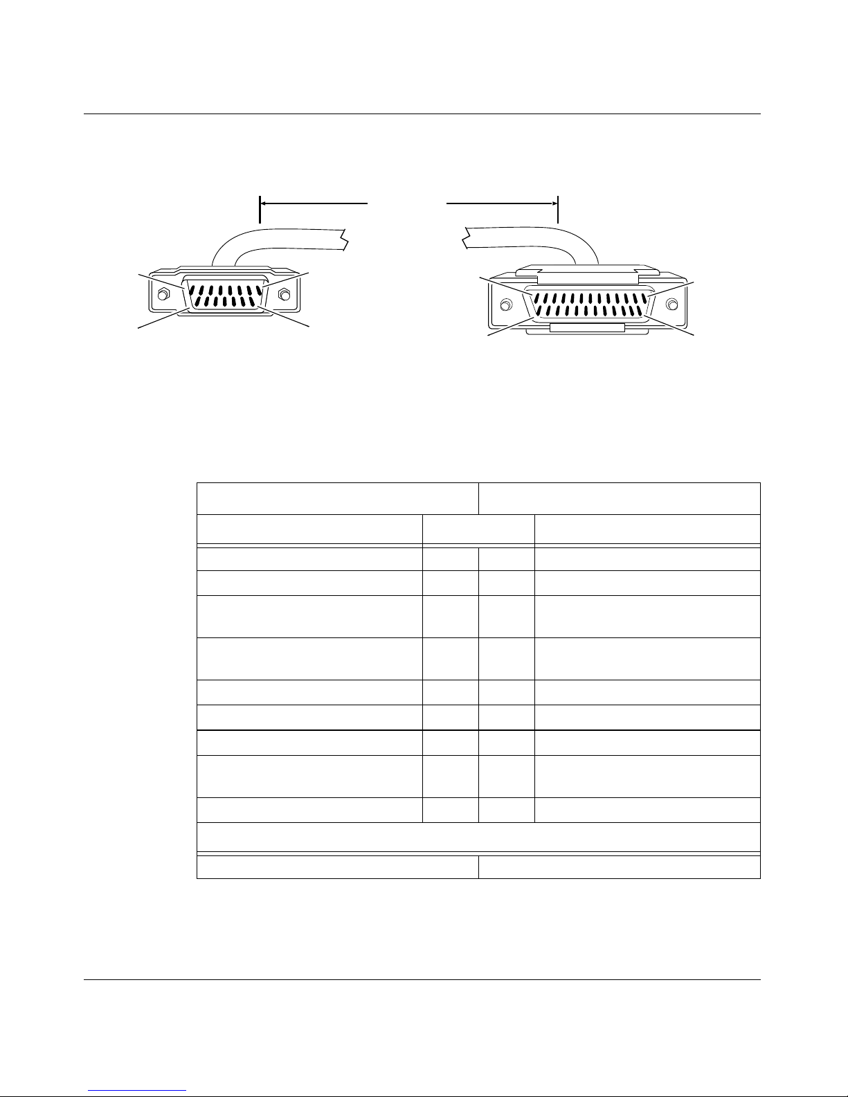
15-Pin D-Sub to RS-232: V.25bis (Order No. 7119)
15 ft
(4.57 m)
Pin 1
Pin 8
P
Pin 1
Document Change Notice
Pin 13
Pin 9
15-position D-sub plug with locking posts
(ground shield connected to backshell)
Industry Interface Type: RS-232-C
Bay Networks Termination Remote Termination
Signal Pin # to Pin # Signal
Signal Ground 1 7 Signal Ground
Transmitted Data 2 2 Transmitted Data
Transmitter Signal Element Timing
(DTE Source)
Transmitter Signal Element Timing
(DCE Source)
Request to Send 6 4 Request to Send
Clear to Send 8 5 Clear to Send
Pin 15
Pin 14
25-position D-sub plug with screw locks
(ground shield connected to backshell)
Pin 25
CAB0006A
3 24 Transmitter Signal Element Timing
(DTE Source)
4 15 Transmitter Signal Element Timing
(DCE Source)
Data Carrier Detect 10 6 Data Set Ready
Receiver Signal Element Timing
(DCE Source)
Received Data 14 3 Received Data
Internal Wire Connections
Pin 1 > 7 Pin 4 > 20 (Data Terminal Ready)
300020-C Rev. 00
12 17 Receiver Signal Elem ent Timing
(DCE Source)
19
Page 34
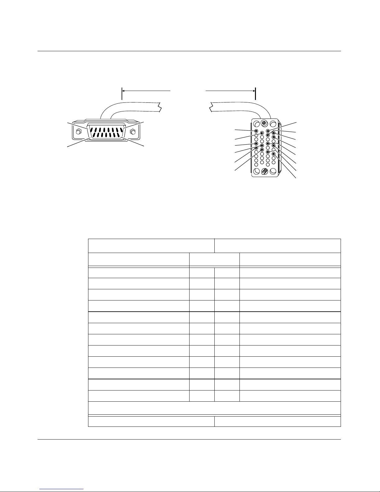
BayRS Version 13.10 Document Change Notice
15-Pin D-Sub to V.35: V.25bis (Order No. 7120)
15 ft
(4.57 m)
Pin 1
Pin 9
15-position D-sub plug with locking posts
(ground shield connected to backshell)
Pin 8
Pin 15
Industry Interface Type: V.35 (V.10 and V.11)
Bay Networks Termination Remote Termination
Signal Pin # to Pin # Signal
Signal Ground 1 B Signal Ground
Send Data + 2 P Send Data A
Send Data - 3 S Send Data B
A
B
D
R
T
V
X
34-position V.35 plug with screw jack retainers
(ground shield connected to backshell)
E
C
H
P
S
Y
AA
CAB0007A
Serial Clock Transmit + 4 Y Send Timing A
Serial Clock Transmit - 5 AA Send Timing B
Request to Send + 6 C Request to Send
Clear to Send + 8 D Clear to Send
Data Carrier Detect + 10 E Data Set Ready
Serial Clock Receive - 11 X Receive Timing B
Serial Clock Receive + 12 V Receive Timing A
Receive Data - 13 T Receive Data B
Receive Data + 14 R Receive Data A
Internal Wire Connections
Pin 1
> 7 Pin C > H (Data Terminal Ready)
20
300020-C Re v. 00
Page 35
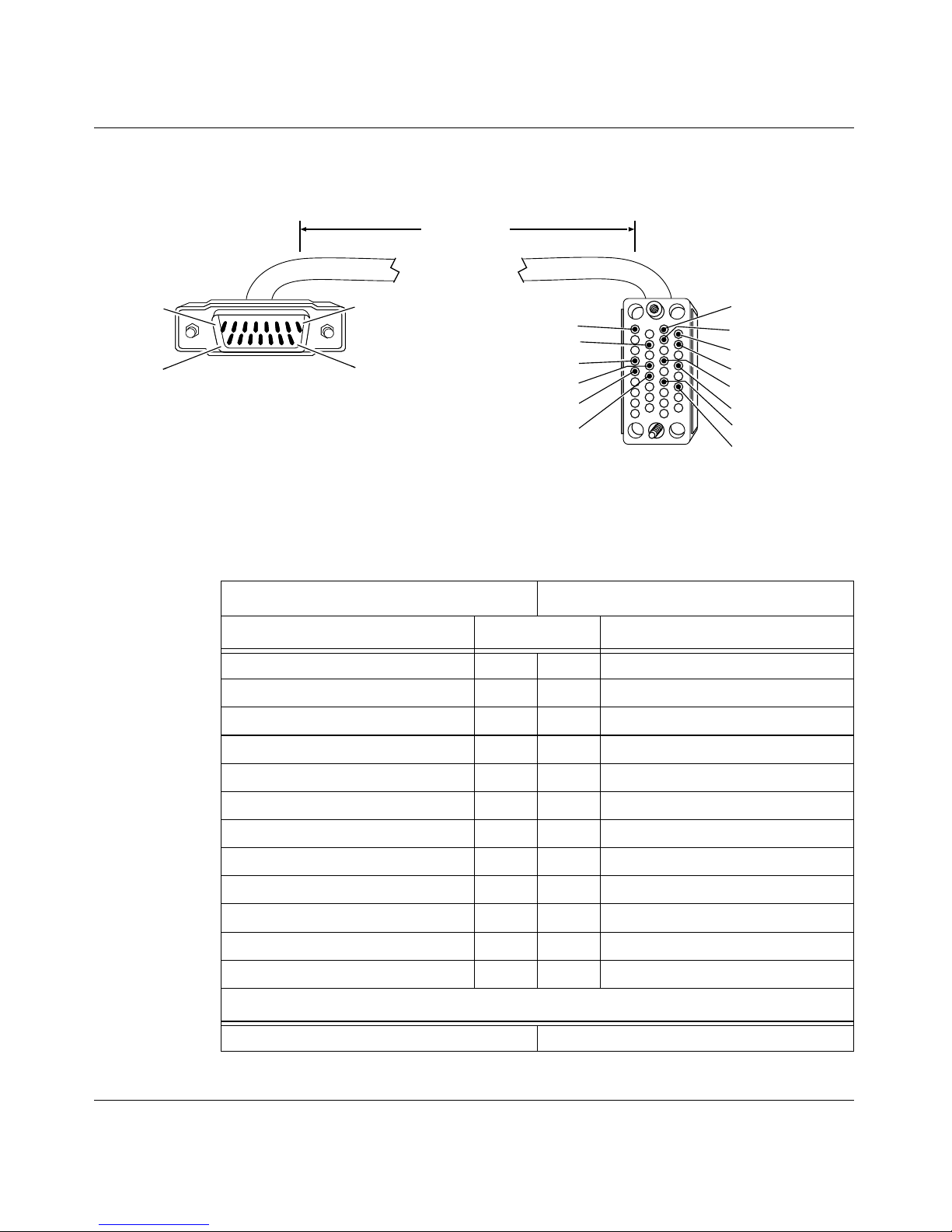
15-Pin D-Sub to V.35: Raise DTR (Order No. 7121)
15 ft
(4.57 m)
Document Change Notice
Pin 1
Pin 9
15-position D-sub plug with locking posts
(ground shield connected to backshell)
Pin 8
Pin 15
Industry Interface Type: V.35 (V.10 and V.11)
Bay Networks Termination Remote Termination
Signal Pin # to Pin # Signal
Signal Ground 1 B Signal Ground
Send Data + 2 P Send Data A
Send Data - 3 S Send Data B
Serial Clock Transmit + 4 Y Send Timing A
A
B
J
R
T
V
X
34-position V.35 plug with screw jack retainers
(ground shield connected to backshell)
E
C
H
P
S
Y
AA
CAB0008A
Serial Clock Transmit - 5 AA Send Timing B
Request to Send + 6 C Request to Send
Clear to Send + 8 E Data Set Ready
Data Carrier Detect + 10 J Ring Indicator
Serial Clock Receive - 11 X Receive Timing B
Serial Clock Receive + 12 V Receive Timing A
Receive Data - 13 T Receive Data B
Receive Data + 14 R Receive Data A
Internal Wire Connections
Pin 1 > 7Pin C >
300020-C Rev. 00
H (Data Terminal Ready)
21
Page 36
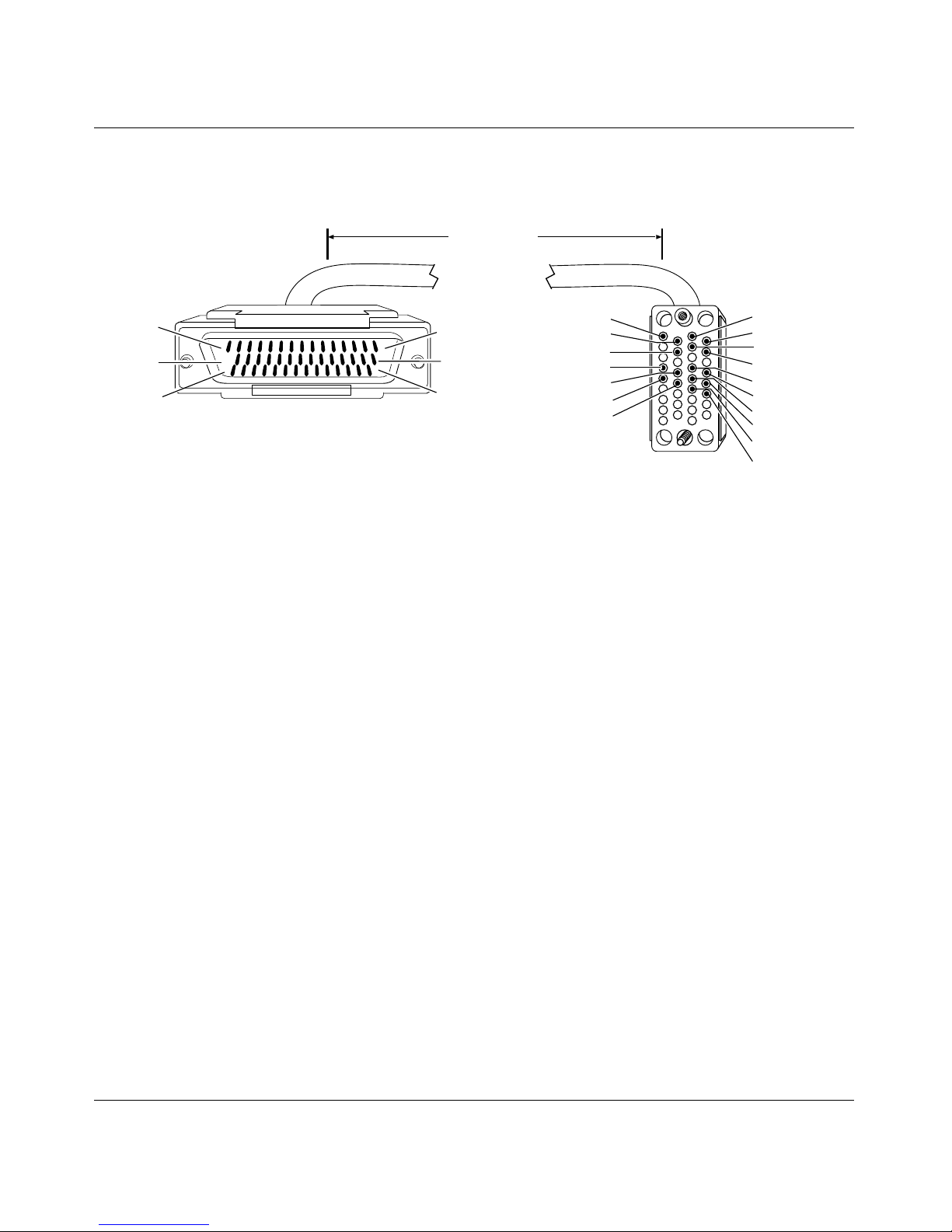
BayRS Version 13.10 Document Change Notice
44-Pin D-Sub to V.35: Raise DTR (Order No. 7137)
15 ft
(4.57 m)
Pin 1
Pin 16
Pin 31
44-position D-sub plug with screw locks
(ground shield connected to backshell)
Industry Interface Type: V.35 (V.10 and V.11)
Pin 15
Pin 30
Pin 44
B
D
J
R
T
V
X
34-position V.35 plug with screw jack retainers
(ground shield connected to backshell)
A
C
E
H
P
S
U
W
Y
AA
CAB0018A
22
300020-C Re v. 00
Page 37

Document Change Notice
Bay Networks Termination Remote Termination
Signal Pin # to Pin # Signal
Frame Ground 1 A Frame Ground
Request to Send + 4 C Request to Send
Clear to Send + 5 D Clear to Send
Data Set Ready + 6 E Data Set Ready
Data Terminal Ready + 8 H Data Terminal Ready
Data Carrier Detect + 9 J Ring Indicator
VTT + 40 U Te rminal Timing A
VTT - 39 W Ter minal Timing B
Signal Ground 19 B Signal Ground
VST + 32 Y Send Timing A
VST - 31 AA Send Timing B
VRT + 34 V Receive Timing A
VRT - 33 X Receive Timing B
VRD + 37 R Receive Data A
VRD - 35 T Receive Data B
VSD + 38 P Send Data A
VSD - 36 S Send Data B
Internal Wire Connections
Pin 7 > 19 > 20
Pin 41 > 42 > 43
Pin 13 > 28
Pin 14 > 29
300020-C Rev. 00
23
Page 38
BayRS Version 13.10 Document Change Notice
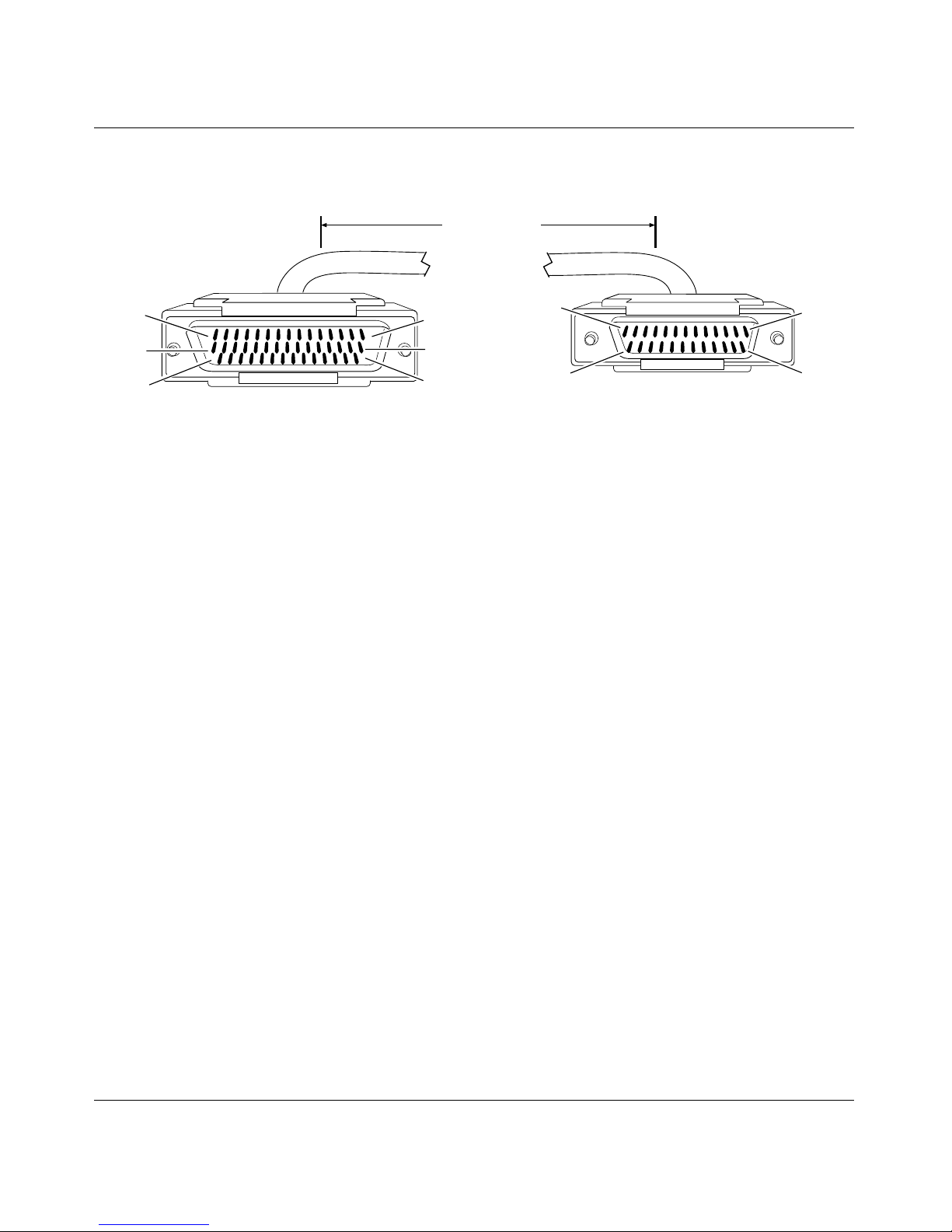
44-Pin D-Sub to RS-232: Raise DTR (Order No. 7138)
15 ft
(4.57 m)
Pin 1
Pin 16
Pin 31
44-position D-sub plug with screw locks
(ground shield connected to backshell)
Industry Interface Type: RS-232-C
Pin 15
Pin 30
Pin 44
Pin 1
Pin 14
25-position D-sub plug with screw locks
(ground shield connected to backshell)
Pin 13
Pin 25
CAB0019A
24
300020-C Re v. 00
Page 39

Document Change Notice
Bay Networks Termination Remote Termination
Signal Pin # to Pin # Signal
Frame Ground 1 1 Frame Ground
Send Data + 2 2 Send Data
Receive Data + 3 3 Receive Data
Request to Send + 4 4 Request to Send
Clear to Send + 5 5 Clear to Send
Data Set Ready + 6 6 Data Set Ready
Signal Ground 7 7 Signal Ground
Data Terminal Ready + 8 20 Data Terminal Ready
Data Carrier Detect + 9 22 Ring Indicator
Send Timing + 10 15 Send Timing
Receive Timing + 11 17 Receive Timing
Transmitter Signal Element Timing + 12 24 Transmitter Signal Element Timing
Internal Wire Connections
Pin 7 > 19 > 20
Pin 13 > 28
Pin 14 > 29
300020-C Rev. 00
25
Page 40
BayRS Version 13.10 Document Change Notice
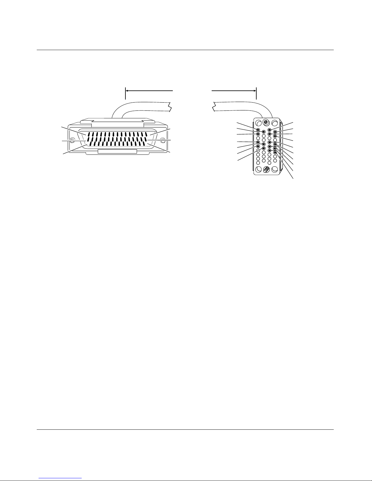
44-Pin to V.35M (Order No. 7159)
10 ft
(3.05 m)
Pin 1
Pin 16
Pin 31
44-position D-sub plug with screw locks
(ground shield connected to backshell)
Industry Interface Type: V.35 (V.10 and V.11)
Pin 15
Pin 30
Pin 44
B
D
F
R
T
V
X
34-position V.35 plug with screw jack retainers
(ground shield connected to backshell)
A
C
E
H
P
S
U
W
Y
AA
CAB0031B
26
300020-C Re v. 00
Page 41

Document Change Notice
Bay Networks Termination Remote Termination
Signal Pin # to Pin # Signal
Frame Ground 1 A Frame Ground
Request to Send + 4 C Request to Send
Clear to Send + 5 D Clear to Send
Data Set Ready + 6 E Data Set Ready
Data Terminal Ready + 8 H Data Terminal Ready
Data Carrier Detect + 9 F Data Carrier Detect
VTT + 40 U Te rminal Timing A
VTT - 39 W Ter minal Timing B
Signal Ground 19 B Signal Ground
VST + 32 Y Send Timing A
VST - 31 AA Send Timing B
VRT + 34 V Receive Timing A
VRT - 33 X Receive Timing B
VRD + 37 R Receive Data A
VRD - 35 T Receive Data B
VSD + 38 P Send Data A
VSD - 36 S Send Data B
Internal Wire Connections
Pin 7 > 19
Pin 41 > 42 > 43
Pin 13 > 28
Pin 14 > 29
> 20
300020-C Rev. 00
27
Page 42
BayRS Version 13.10 Document Change Notice
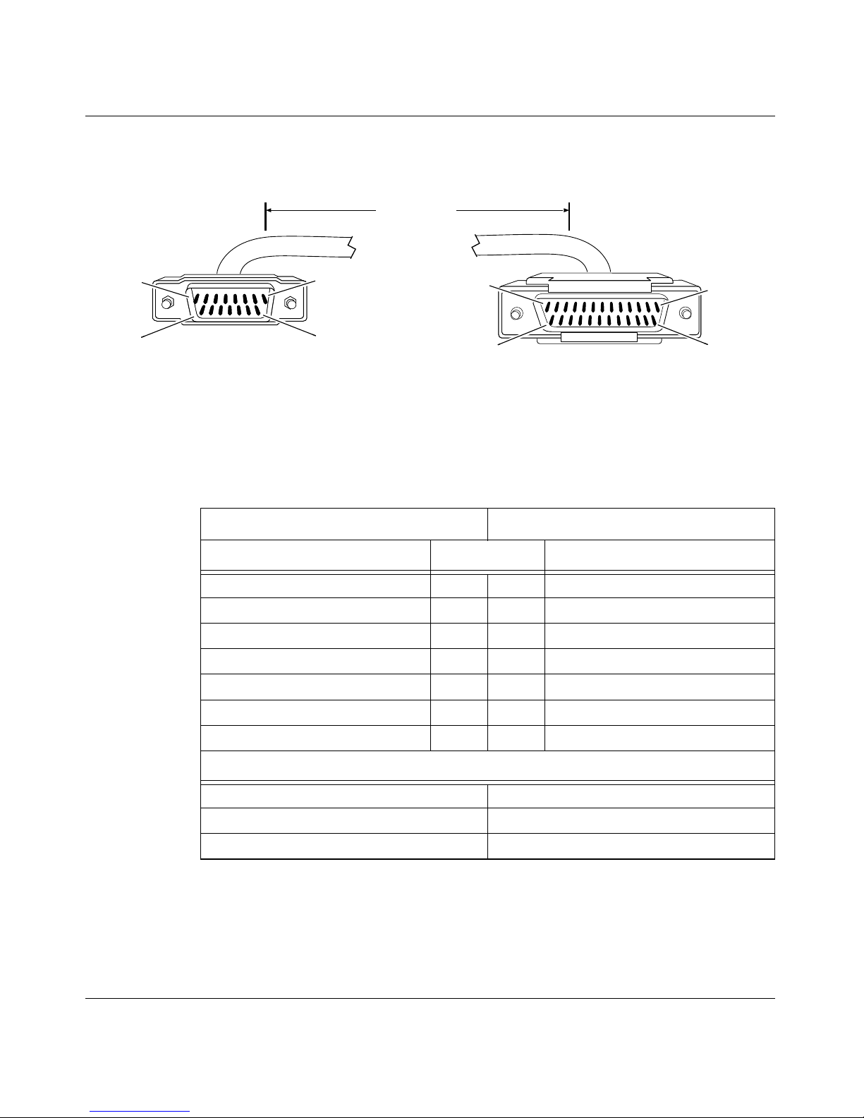
RS-232 Pass-Through: 15-Pin to RS-232 (Order No. 7218)
15 ft
(4.57 m)
Pin 1
Pin 9
15-position D-sub plug with locking posts
(ground shield connected to backshell)
Industry Interface Type: RS-232-C
Bay Networks Termination Remote Termination
Signal Pin # to Pin # Signal
Signal Ground 1 7 Signal Ground
Transmitted Data 2 3 Received Data
Transmit Clock 4 15 Transmit Clock
Data Set Ready 6 8 Data Carrier Detect
Data Carrier Detect 10 4 Clear to Send
Pin 8
Pin 15
Pin 1
Pin 14
25-position D-sub plug with screw locks
(ground shield connected to backshell)
Pin 13
Pin 25
CAB0041A
Receive Clock 12 17 Receive Clock
Received Data 14 2 Transmitted Data
Internal Wire Connections
> 7Pin 4
Pin 1
Pin 6
> 8Pin 6
> 4 >12
Pin 3
28
> 5
> 20
300020-C Re v. 00
Page 43
Document Change Notice
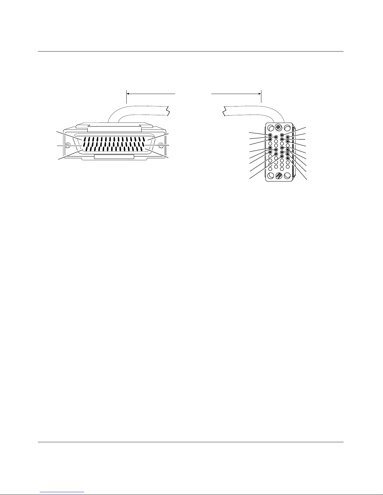
44-Pin D-Sub to V.35: Leased Line or V.25bis (Order No. 7220)
15 ft
(4.57 m)
Pin 1
Pin 16
Pin 31
44-position D-sub plug with screw locks
(ground shield connected to backshell)
Pin 15
Pin 30
Pin 44
Industry Interface Type: V.35 (V.10 and V.11)
B
D
F
R
T
V
X
Y
34-position V.35 plug with screw jack retainers
(ground shield connected to backshell)
A
C
E
H
P
S
U
W
AA
CAB0106A
300020-C Rev. 00
29
Page 44

BayRS Version 13.10 Document Change Notice
Bay Networks Termination Remote Termination
Signal Pin # to Pin # Signal
VSD + 38 P Send Data A
VSD - 36 S Send Data B
VRT + 34 V Receive Timing A
VRT - 33 X Receive Timing B
VST + 32 Y Send Timing A
VST - 31 AA Send Timing B
VRD + 37 R Receive Data A
VRD - 35 T Receive Data B
Data Set Ready + 6 E Data Set Ready
Data Terminal Ready + 8 H Data Terminal Ready
Request to Send + 4 C Request to Send
Clear to Send + 5 D Clear to Send
VTT + 40 U Terminal Timing A
VTT - 39 W Terminal Timing B
Frame Ground 1 A Frame Ground
Data Carrier Detect + 9 F Data Carrier Detect
Signal Ground 19 B Signal Ground
Internal Wire Connections
Pin 7
> 19 > 20
Pin 41
Pin 13
Pin 14
> 42 > 43
> 28
> 29
30
300020-C Re v. 00
Page 45
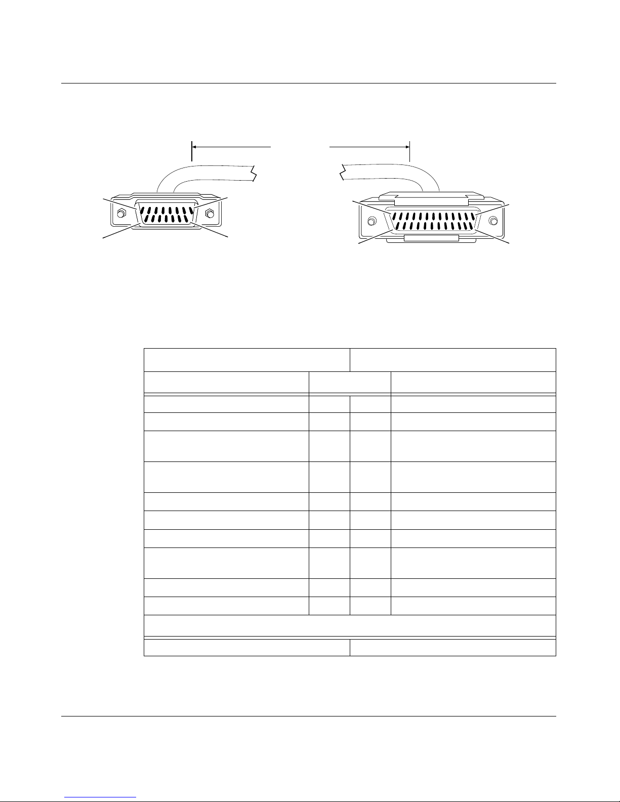
15-Pin D-Sub to RS-232 (Order No. 7255)
15 ft
(4.57 m)
Document Change Notice
Pin 1
Pin 9
15-position D-sub plug with locking posts
(ground shield connected to backshell)
Industry Interface Type: RS-232-C
Bay Networks Termination Remote Termination
Signal Pin # to Pin # Signal
Signal Ground 1 7 Signal Ground
Transmitted Data 2 2 Transmitted Data
Transmitter Signal Element Timing
(DTE Source)
Transmitter Signal Element
Timing (DCE Source)
Pin 8
Pin 15
Pin 1
Pin 14
25-position D-sub plug with screw locks
(ground shield connected to backshell)
Pin 13
Pin 25
CAB0045A
3 24 Transmitter Signal Element Timing
(DTE Source)
4 15 Transmitter Signal Element
Timing (DCE Source)
Request to Send 6 4 Request to Send
Clear to Send 8 5 Clear to Send
Carrier Detect 10 8 Carrier Detect
Receiver Sign al Element
Timing (DCE Source)
Received Data 14 3 Received Data
Data Set Ready 15 6 Data Set Ready
Internal Wire Connections
> 7Pin 4
Pin 1
300020-C Rev. 00
12 17 Receiver Signal Element
Timing (DCE Source)
> 20
31
Page 46
BayRS Version 13.10 Document Change Notice
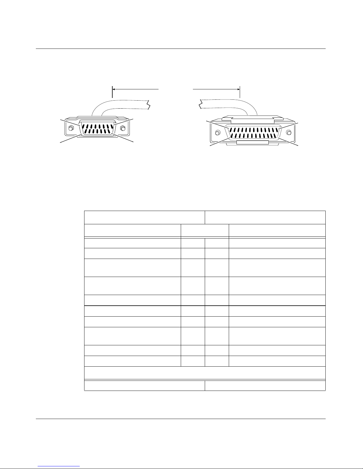
15-Pin D-Sub to V.28 (Order No. 7256)
15 ft
(4.57 m)
Pin 1
Pin 9
15-position D-sub plug with locking posts
(ground shield connected to backshell)
Pin 8
Pin 15
Industry Interface Type: V.28 (V.10)
Bay Networks Termination Remote Termination
Signal Pin # to Pin # Signal
Signal Ground 1 7 Signal Ground
Transmitted Data 2 2 Transmitted Data
Transmitter Timing
(DTE Source)
Transmitter Signal Element Timing
(DCE Source)
Pin 1
Pin 14
25-position D-sub plug with M-3 jack screws
(ground shield connected to backshell)
Pin 13
Pin 25
CAB0045B
3 24 Transmitter Signal Element
Timing (DTE Source)
4 15 Transmitter Signal Element Timing
(DCE Source)
Request to Send 6 4 Request to Send
Clear to Send 8 5 Clear to Send
Carrier Detect 10 8 Carrier Detect
Receiver Sign al Element
Timing (DCE Source)
Received Data 14 3 Received Data
Data Set Ready 15 6 Data Set Ready
Internal Wire Connections
> 7Pin 4
Pin 1
32
12 17 Receiver Signal Element
Timing (DCE Source)
> 20
300020-C Re v. 00
Page 47
Document Change Notice
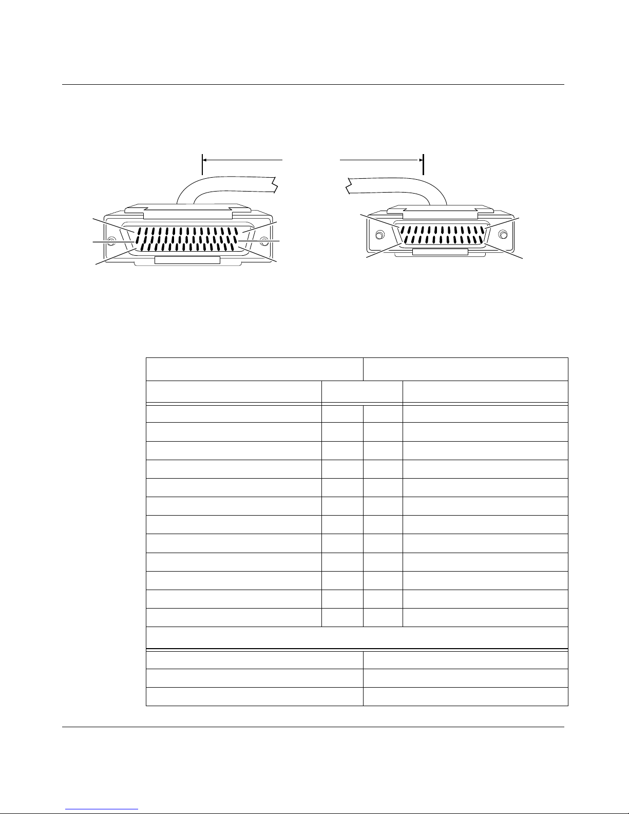
44-Pin D-Sub to RS-232: Leased Line or V.25bis (Order No. 7826)
15 ft
(4.57 m)
in 1
Pin 16
Pin 31
44-position D-sub plug with screw locks
(ground shield connected to backshell)
Industry Interface Type: RS-232-C
Bay Networks Termination Remote Termination
Signal Pin # to Pin # Signal
Frame Ground 1 1 Frame Ground
Send Data + 2 2 Send Data
Receive Data + 3 3 Receive Data
Request to Send + 4 4 Request to Send
Clear to Send + 5 5 Clear to Send
Data Set Ready + 6 6 Data Set Ready
Pin 15
Pin 30
Pin 44
Pin 1
Pin 14
25-position D-sub plug with screw locks
(ground shield connected to backshell)
Pin 13
Pin 25
CAB0069A
Data Terminal Ready + 8 20 Data Terminal Ready
Data Carrier Detect + 9 8 Data Carrier Detect
Send Timing + 10 15 Send Timing
Receive Timing + 11 17 Receive Timi ng
Transmitter Signal Element Timing + 12 24 Transmitter Signal Element Timing
Signal Ground 7 7 Signal Ground
Internal Wire Connections
Pin 7 > 19 > 20
Pin 13
Pin 14
> 28
> 29
300020-C Rev. 00
33
Page 48
BayRS Version 13.10 Document Change Notice
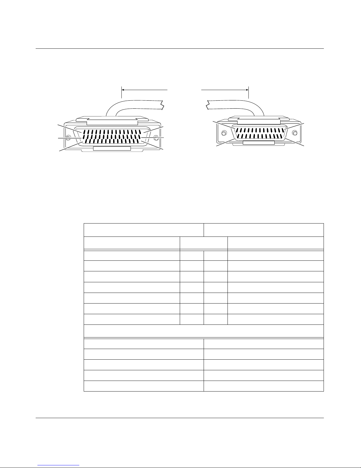
RS-232 Pass-Through: 44-Pin to RS-232 (Order No. 7833)
15 ft
(4.57 m)
Pin 1
Pin 16
Pin 31
44-position D-sub plug with screw locks
(ground shield connected to backshell)
Industry Interface Type: RS-232-C
Bay Networks Termination Remote Termination
Signal Pin # to Pin # Signal
Receive Data + 3 2 Send Data
Send Data + 2 3 Receive Data
Data Carrier Detect + 9 5 Clear to Send
RTS + 4 8 Data Carrier Detect
Pin 15
Pin 30
Pin 44
Pin 1
Pin 14
25-position D-sub plug with screw locks
(ground shield connected to backshell)
Pin 13
Pin 25
CAB0065A
Send Timing + 10 17 Receive Timing
Frame Ground 1 1 Frame Ground
Signal Ground 7 7 Signal Ground
Internal Wire Connections
Pin 4 > 5Pin 4 >
Pin 10 > 11 > 12 Pin 15 > 17
Pin 7 > 19 > 20 Pin 6 > 20
Pin 13 > 28
Pin 14 > 29
34
5
300020-C Re v. 00
Page 49
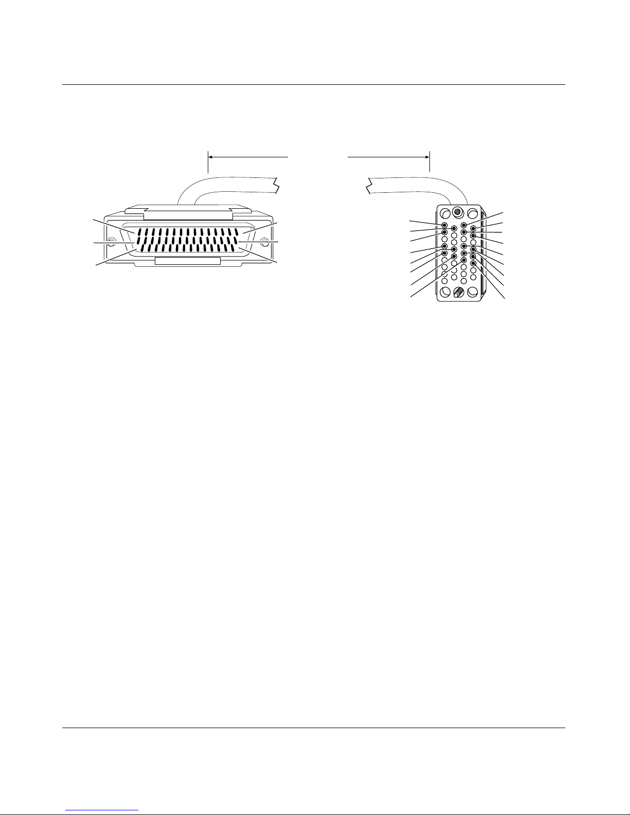
V.35 Pass-Through: 44-Pin to V.35 (Order No. 7834)
15 ft
(4.57 m)
Document Change Notice
Pin 1
Pin 16
Pin 31
44-position D-sub plug with screw locks
(ground shield connected to backshell)
Pin 15
Pin 30
Pin 44
Industry Interface Type: V.35 (V.10 and V.11)
B
D
F
R
T
V
X
Y
34-position V.35 plug with screw jack retainers
(ground shield connected to backshell)
A
C
E
H
P
S
U
W
AA
CAB0106A
300020-C Rev. 00
35
Page 50

BayRS Version 13.10 Document Change Notice
Bay Networks Termination Remote Termination
Signal Pin # to Pin # Signal
VSD + 38 R Receive Data A
VSD - 36 T R eceive Data B
VRD + 37 P Send Data A
VRD - 35 S Send Data B
Request to Send + 4 F Data Carrier Detect
Data Carrier Detect + 9 D Clear to Send
VTT + 40 V Receive Timin g A
VTT - 39 X Receive Timin g B
Frame Ground 1 A Frame Ground
Signal Ground 7 B Signal Ground
Internal Wire Connections
Pin 4 > 5Pin C >
D
Pin 32 > 34 > 40 Pin V > Y
Pin 31 > 33 > 39 Pin X > AA
Pin 7 > 19 > 20 > 41 > 42 Pin E > H
Pin 13 > 28
Pin 14 > 29
36
300020-C Re v. 00
Page 51
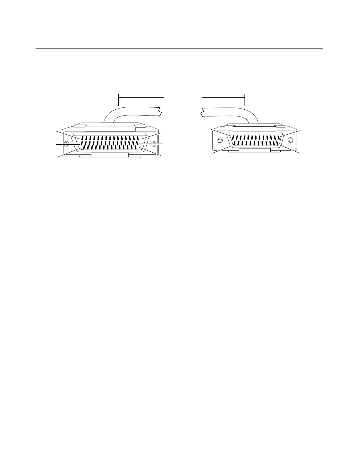
44-Pin D-Sub to V.28 (Order No. 7837)
15 ft
(4.57 m)
Document Change Notice
Pin 1
Pin 16
Pin 31
44-position D-sub plug with screw locks
(ground shield connected to backshell)
Industry Interface Type: V.28 (V.10)
Pin 15
Pin 30
Pin 44
Pin 1
Pin 14
25-position D-sub plug with M-3 jack screws
(ground shield connected to backshell)
Pin 13
Pin 25
CAB0069B
300020-C Rev. 00
37
Page 52

BayRS Version 13.10 Document Change Notice
Bay Networks Termination Remote Termination
Signal Pin # to Pin # Signal
Frame Ground 1 1 Frame Ground
Send Data + 2 2 Send Data
Receive Data + 3 3 Receive Data
Request to Send + 4 4 Request to Send
Clear to Send + 5 5 Clear to Send
Data Set Ready + 6 6 Data Set Ready
Data Terminal Ready + 8 20 Data Terminal Ready
Data Carrier Detect + 9 8 Data Carrier Detect
Send Timing + 10 15 Send Timing
Receive Timing + 11 17 Receive Timing
Transmitter Signal Element
12 24 Transmitter Signal Element Ti ming
Timing +
Signal Ground 7 7 Signal Ground
Internal Wire Connections
Pin 7 > 19 > 20
Pin 13 > 28
Pin 14 > 29
38
300020-C Re v. 00
Page 53
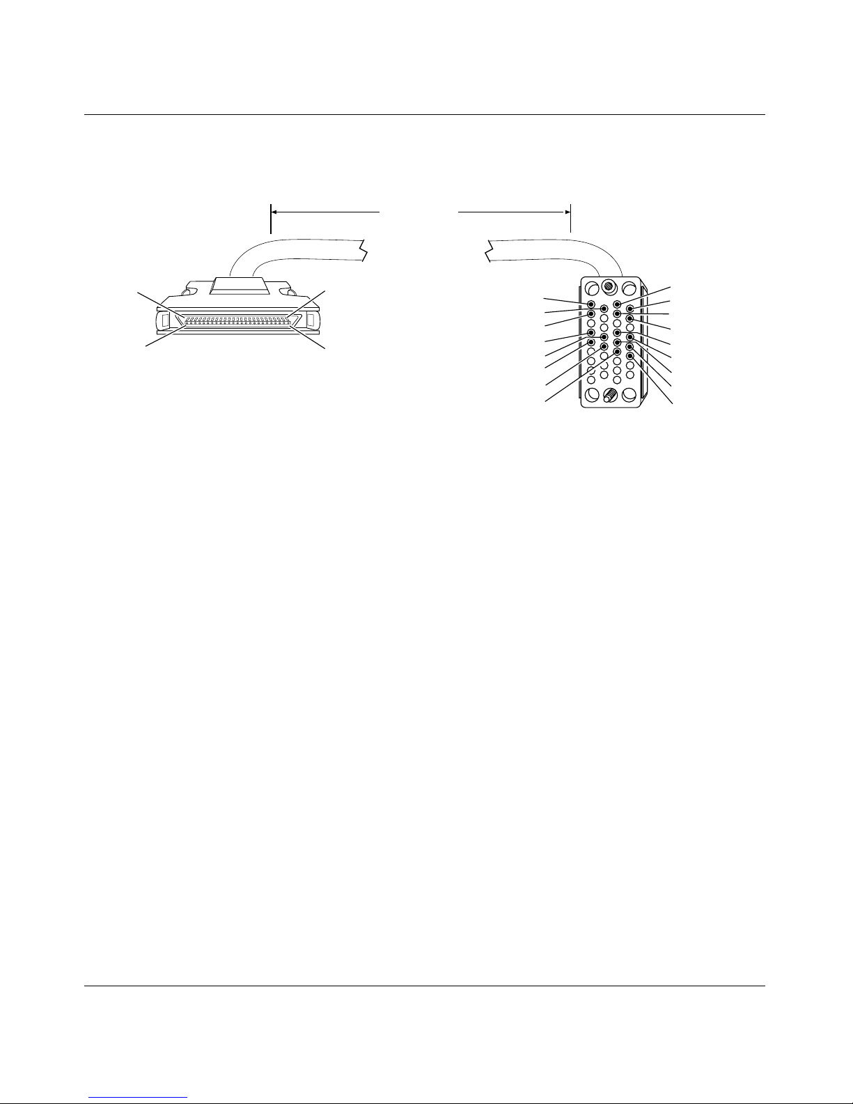
50-Pin to V.35 (Order No. 7932)
Document Change Notice
15 ft
(4.57 m)
Pin 1
Pin 26
50-position 0.8-mm plug
(ground shield connected to internal shell)
Pin 25
Pin 50
Industry Interface Type: V.35 (V.10 and V.11)
B
D
F
R
T
V
X
Y
34-position V.35 plug with screw jack retainers
(ground shield connected to backshell)
A
C
E
H
P
S
U
W
AA
CAB0070A
300020-C Rev. 00
39
Page 54

BayRS Version 13.10 Document Change Notice
Bay Networks Termination Remote Termination
Signal Pin # to Pin # Signal
VSD + 44 P Send Data A
VSD - 19 S Send Data B
VRT + 42 V Receive Timing A
VRT - 17 X Receive Timing B
VST + 41 Y Send Timing A
VST - 16 AA Send Timing B
VRD + 43 R Receive Data A
VRD - 18 T Receive Data B
Data Set Ready + 6 E Data Set Ready
Data Terminal Ready + 8 H D a ta Terminal Ready
Request to Send + 4 C Request to Send
Clear to Send + 5 D Clear to Send
VTT + 45 U Terminal Timing A
VTT - 20 W Terminal Timing B
Frame Ground 1 A Frame Ground
Data Carrier Detect 9 F Data Carrier Detect
Signal Ground 30 B Signal Ground
Internal Wire Connections
Pin 7 > 30
Pin 46 > 47 > 48
Pin 13 > 38
Pin 14 > 39
> 31
40
300020-C Re v. 00
Page 55
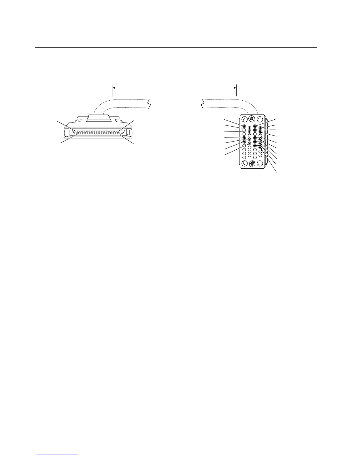
50-Pin to V.35: Raise DTR (Order No. 7933)
15 ft
(4.57 m)
Document Change Notice
Pin 1
Pin 26
50-position 0.8-mm plug
(ground shield connected to internal shell)
Pin 25
Pin 50
Industry Interface Type: V.35 (V.10 and V.11)
B
D
J
R
T
V
X
34-position V.35 plug with screw jack retainers
(ground shield connected to backshell)
A
C
E
H
P
S
U
W
Y
AA
CAB0071A
300020-C Rev. 00
41
Page 56

BayRS Version 13.10 Document Change Notice
Bay Networks Termination Remote Termination
Signal Pin # to Pin # Signal
VSD + 44 P Send Data A
VSD - 19 S Send Data B
VRT + 42 V Receive Timing A
VRT - 17 X Receive Timing B
VST + 41 Y Send Timing A
VST - 16 AA Send Timing B
VRD + 43 R Receive Data A
VRD - 18 T Receive Data B
Data Set Ready + 6 E Data Set Ready
Data Terminal Ready + 8 H D a ta Terminal Ready
Request to Send + 4 C Request to Send
Clear to Send + 5 D Clear to Send
VTT + 45 U Terminal Timing A
VTT - 20 W Terminal Timing B
Frame Ground 1 A Frame Ground
Data Carrier Detect + 9 J Ring Indicator
Signal Ground 30 B Signal Ground
Internal Wire Connections
Pin 7 > 30 > 31
Pin 46 > 47 > 48
Pin 13 > 38
Pin 14 > 39
42
300020-C Re v. 00
Page 57
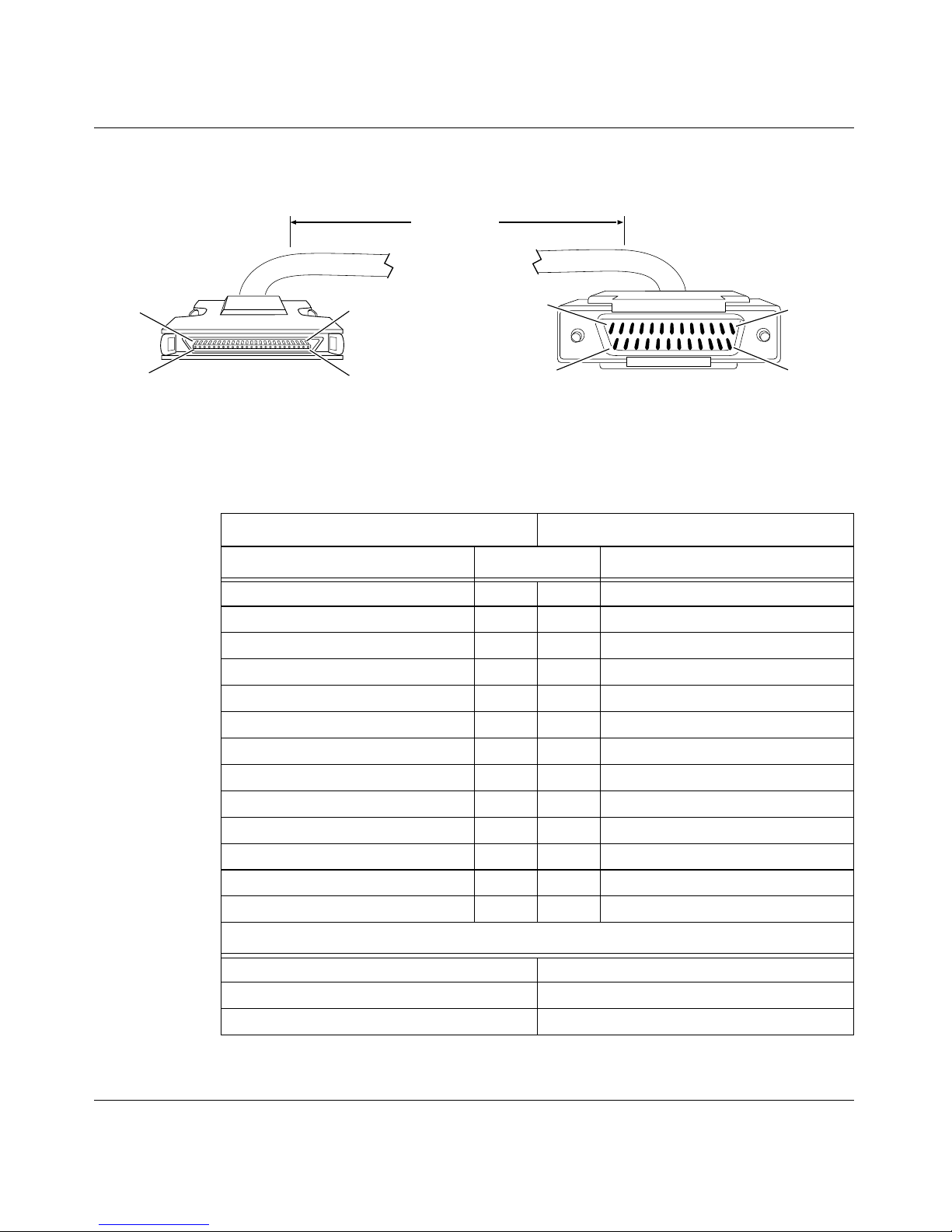
50-Pin to RS-232 (Order No. 7934)
15 ft
(4.57 m)
Document Change Notice
Pin 1
Pin 26
50-position 0.8-mm plug
(ground shield connected to internal shell)
Industry Interface Type: RS-232-C
Bay Networks Termination Remote Termination
Signal Pin # to Pin # Signal
Frame Ground 1 1 Frame Ground
Send Data + 2 2 Send Data
Receive Data + 3 3 Receive Data
Request to Send + 4 4 Request to Send
Clear to Send + 5 5 Clear to Send
Data Set Ready + 6 6 Data Set Ready
Signal Ground 7 7 Signal Ground
Data Terminal Ready + 8 20 Data Terminal Ready
Data Carrier Detect + 9 8 Data Carrier Detect
Send Timing + 10 15 Send Timing
Receive Timing + 11 17 Receive Timing
Terminal Timing + 12 24 Terminal Timing
Signal Ground 7 7 Signal Ground
Pin 25
Pin 50
Pin 1
Pin 14
25-position D-sub plug with screw locks
(ground shield connected to backshell)
Pin 13
Pin 25
CAB0073A
Internal Wire Connections
Pin 7 > 30 > 31
Pin 13 > 38
Pin 14 > 39
300020-C Rev. 00
43
Page 58
BayRS Version 13.10 Document Change Notice
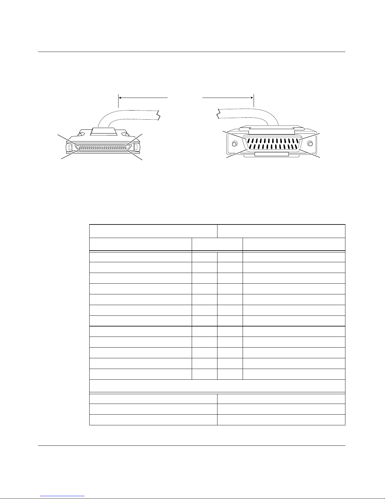
50-Pin to RS-232: Raise DTR (Order No. 7935)
15 ft
(4.57 m)
Pin 1
Pin 26
50-position 0.8-mm plug
(ground shield connected to internal shell)
Industry Interface Type: RS-232-C
Bay Networks Termination Remote Termination
Signal Pin # to Pin # Signal
Frame Ground 1 1 Frame Ground
Send Data + 2 2 Send Data
Receive Data + 3 3 Receive Data
Request to Send + 4 4 Request to Send
Clear to Send + 5 5 Clear to Send
Data Set Ready + 6 6 Data Set Ready
Data Terminal Ready + 8 20 Data Terminal Ready
Data Carrier Detect + 9 22 Ring Indicator
Send Timing + 10 15 Send Timing
Receive Timing + 11 17 Receive Timing
Terminal Timing + 12 24 Terminal Timing
Signal Ground 7 7 Signal Ground
Pin 25
Pin 50
Pin 1
Pin 14
25-position D-sub plug with screw locks
(ground shield connected to backshell)
Pin 13
Pin 25
CAB0072A
Internal Wire Connections
Pin 7 > 30 > 31
Pin 13 > 38
Pin 14 > 39
44
300020-C Re v. 00
Page 59
Document Change Notice
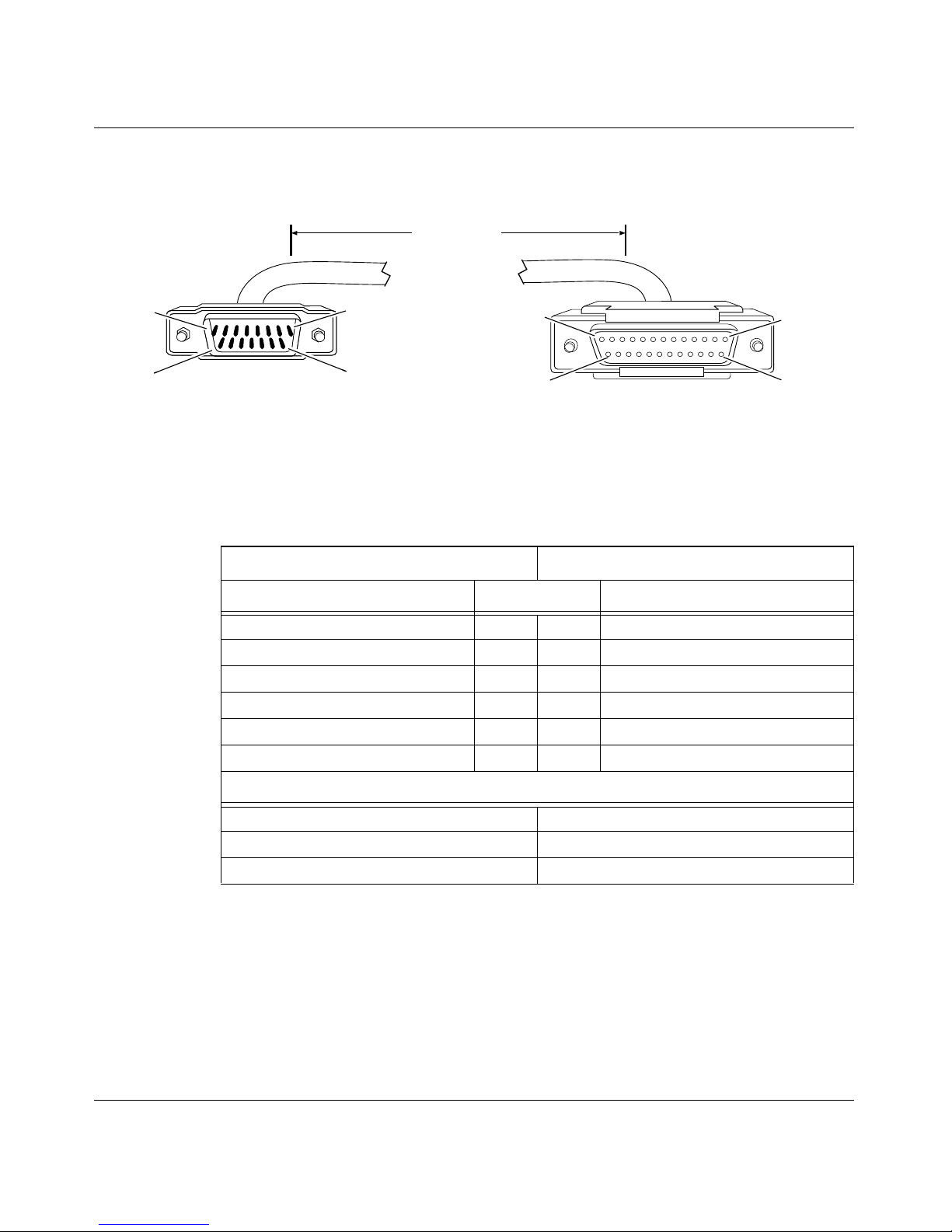
15-Pin to F RS-232 Synchronous Pass-Through (Order No. 7941)
15 ft
(4.57 m)
Pin 1
Pin 9
15-position D-sub plug with locking posts
(ground shield connected to backshell)
Industry Interface Type: RS-232-C
Bay Networks Termination Remote Termination
Signal Pin # to Pin # Signal
Transmit Data 2 3 Receive Data
Receive Data 14 2 Transmit Data
Request to Send 6 8 Data Carrier Detect
Data Carrier Detect 10 4 Request to Send
Transmit Clock 4 15 Transmit Clock
Signal Ground 1 7 Signal Ground
Pin 8
Pin 15
Pin 13
Pin 25
25-position D-sub receptacle with screw locks
(ground shield connected to backshell)
Pin 1
Pin 14
CAB0079A
Internal Wire Connections
Pin 6 > 8Pin 4 >
Pin 3 > 4 > 12 Pin 15 > 17
Pin 1 > 7Pin 6 >
300020-C Rev. 00
5
20
45
Page 60
BayRS Version 13.10 Document Change Notice
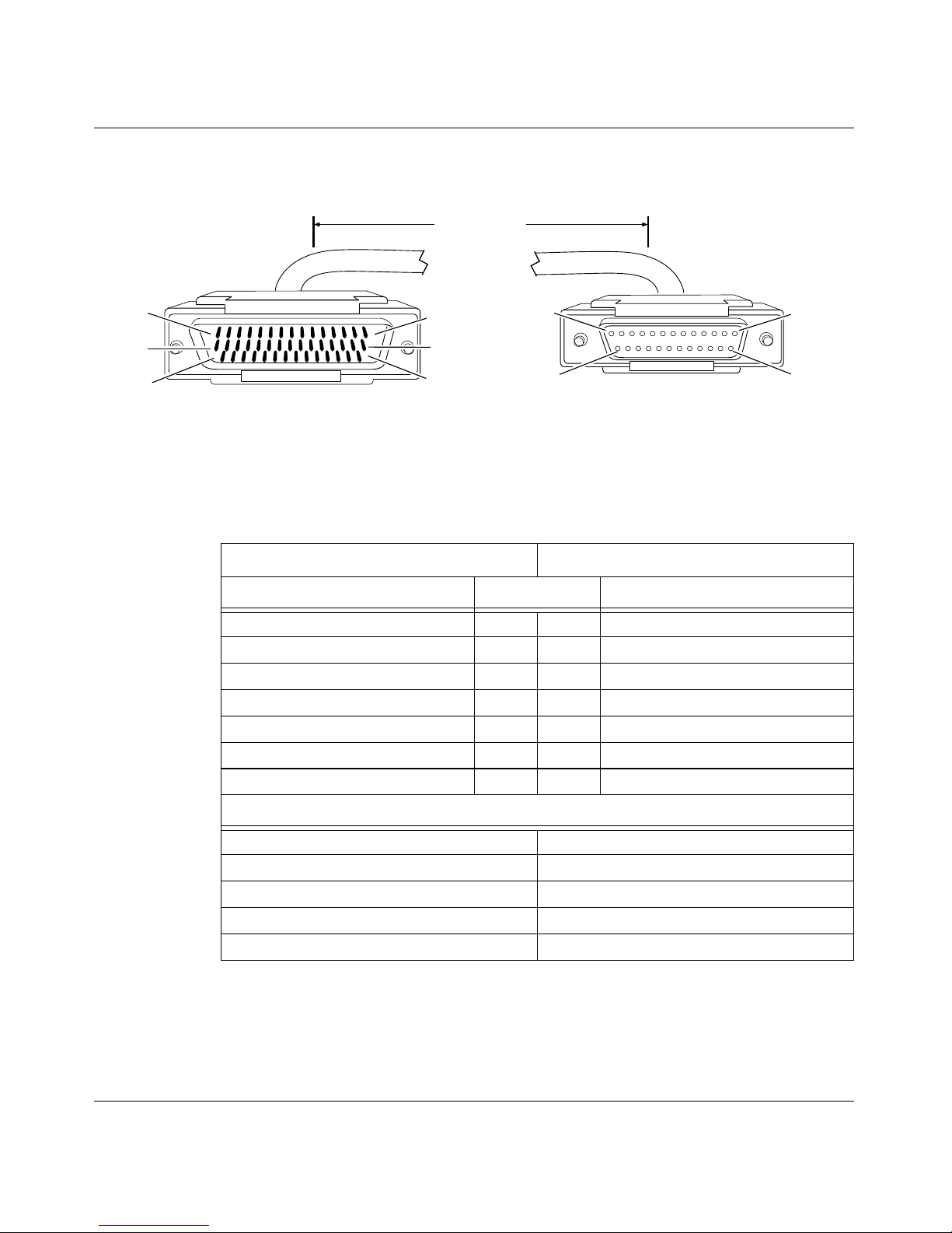
44-Pin to F RS-232 Synchronous Pass-Through (Order No. 7943)
15 ft
(4.57 m)
Pin 1
Pin 16
Pin 31
44-position D-sub plug with screw locks
(ground shield connected to backshell)
Industry Interface Type: RS-232-C
Bay Networks Termination Remote Termination
Signal Pin # to Pin # Signal
Send Data + 2 3 Receive Data
Receive Data + 3 2 Send Data
Request to Send + 4 8 Data Carrier Detect
Data Carrier Detect + 9 4 Request to Send
Send Timing + 10 15 Send Timing
Frame Ground 1 1 Frame Ground
Signal Ground 7 7 Signal Ground
Pin 15
Pin 30
Pin 44
Pin 13
Pin 25
25-position D-sub receptacle with screw locks
(ground shield connected to backshell)
Pin 1
Pin 14
CAB0081A
Internal Wire Connections
Pin 4 > 5Pin 4 >
Pin 10 > 11 > 12 Pin 15 > 17
Pin 13 > 28 Pin 6 > 20
Pin 14 > 29
Pin 7 > 19 > 20
46
5
300020-C Re v. 00
Page 61
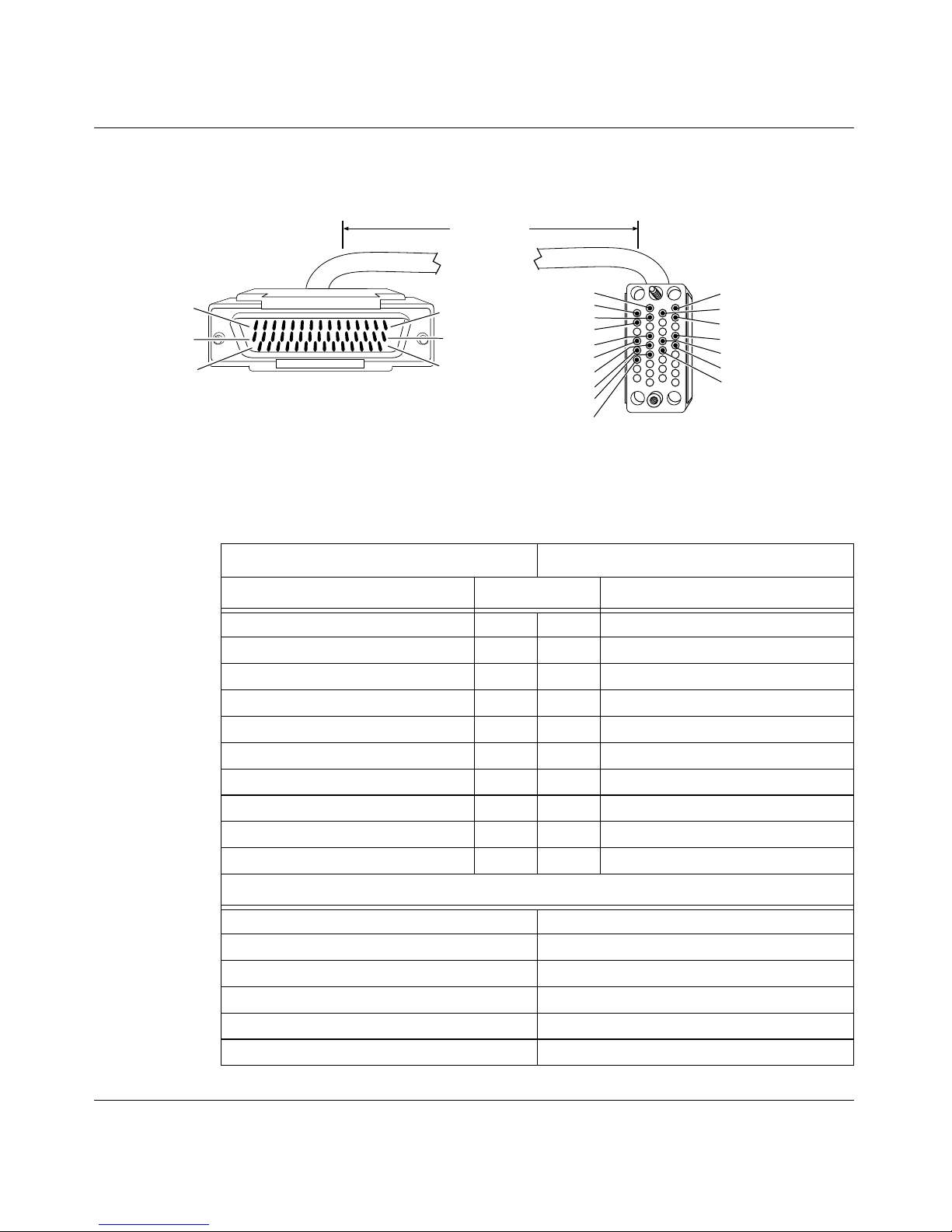
Document Change Notice
44-Pin to F V.35 Synchronous Pass-Through (Order No. 7944)
15 ft
(4.57 m)
Pin 1
Pin 16
Pin 31
44-position D-sub plug with screw locks
(ground shield connected to backshell)
Industry Interface Type: V.35 (V.10 and V.11)
Bay Networks Termination Remote Termination
Signal Pin # to Pin # Signal
VSD + 38 R Receive Data A
VSD - 36 T Receive Data B
VRD + 37 P Send Data A
VRD - 35 S Send Data B
Request to Send + 4 F Data Carrier Detect
Data Carrier Detect + 9 C Request to Send
VTT + 40 Y Send Timing A
VTT - 39 AA Send Timing B
Frame Ground 1 A Frame Ground
Signal Ground 7 B Signal Ground
Pin 15
Pin 30
Pin 44
A
C
E
H
P
S
U
W
Y
AA
34-position V.35 receptacle with screw jack retainers
(ground shield connected to backshell)
B
D
F
R
T
V
X
CAB0082A
Internal Wire Connections
Pin 4 > 5Pin C >
Pin 32 > 34 > 40 Pin V > Y
Pin 31 > 33 > 39 Pin X > AA
Pin 13 > 28 Pin E > H
Pin 14 > 29
Pin 7 > 19 > 20 > 41 > 42
300020-C Rev. 00
D
47
Page 62
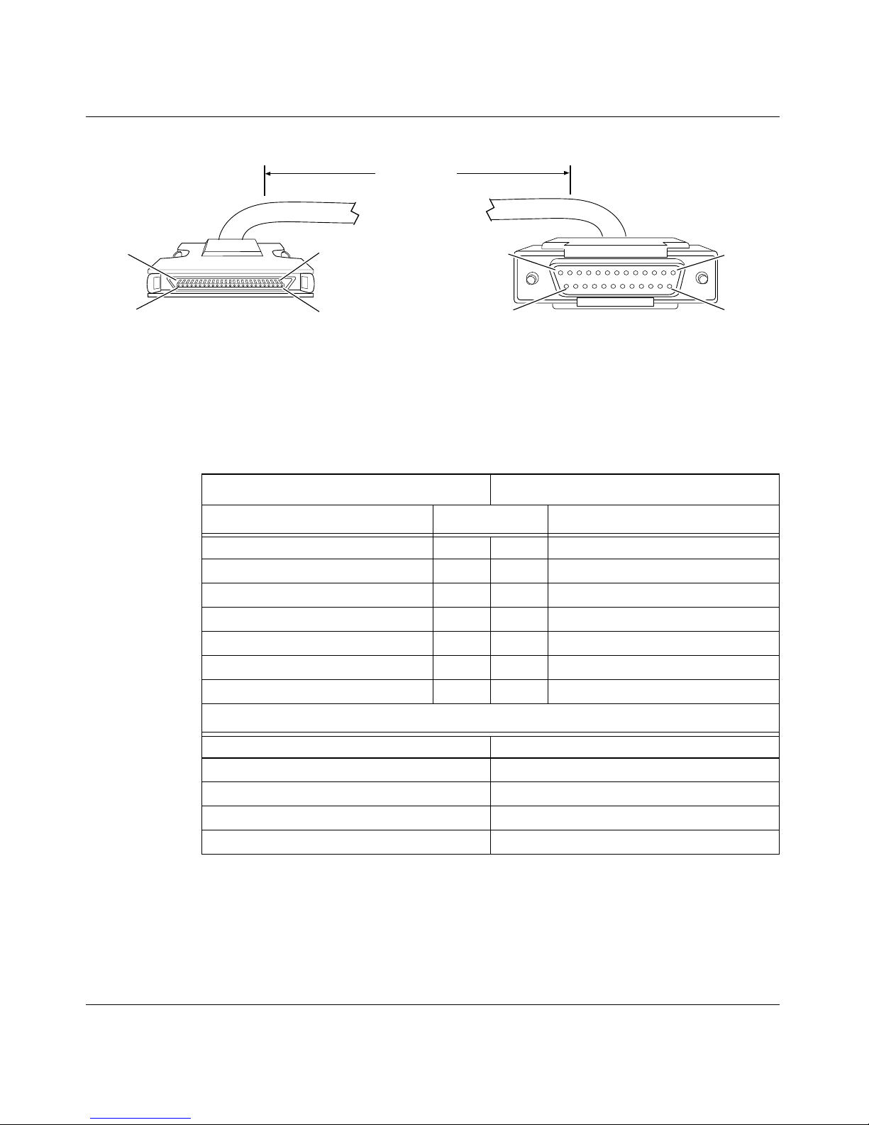
BayRS Version 13.10 Document Change Notice
50-Pin to F RS-232 Synchronous Pass-Through (Order No. 7945)
15 ft
(4.57 m)
Pin 1
Pin 26
50-position 0.8-mm plug
(ground shield connected to internal shell)
Industry Interface Type: RS-232-C
Bay Networks Termination Remote Termination
Signal Pin # to Pin # Signal
Send Data + 2 3 Receive Data
Receive Data + 3 2 Send Data
Request to Send + 4 8 Data Carrier Detect
Data Carrier Detect + 9 4 Request to Send
Send Timing + 10 15 Send Timing
Frame Ground 1 1 Frame Ground
Signal Ground 7 7 Signal Ground
Pin 25
Pin 50
Pin 13
Pin 25
25-position D-sub receptacle with screw locks
(ground shield connected to backshell)
Pin 1
Pin 14
CAB0083A
Internal Wire Connections
Pin 4 > 5Pin 4 >
Pin 10 > 11 > 12 Pin 15 > 17
Pin 13 > 38 Pin 6 > 20
Pin 14 > 39
Pin 7 > 30 > 31
48
5
300020-C Re v. 00
Page 63
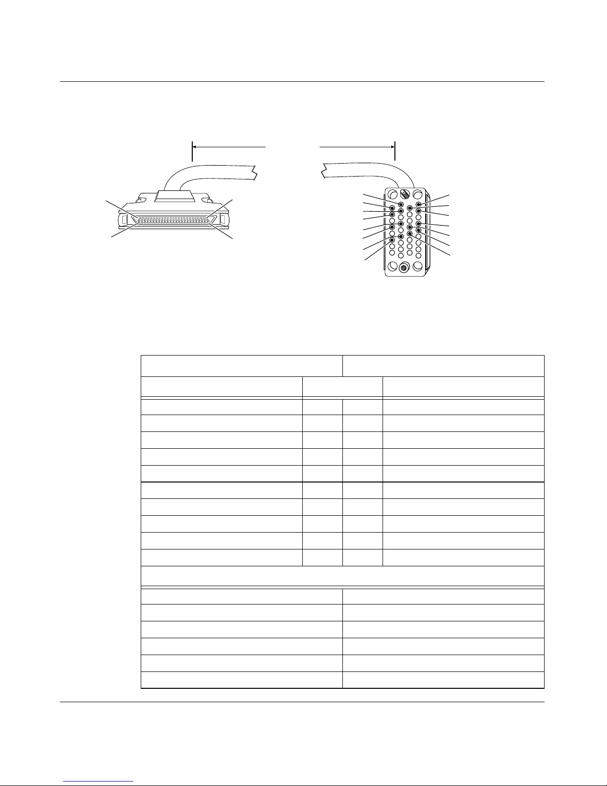
Document Change Notice
50-Pin to F V.35 Synchronous Pass-Through (Order No. 7946)
15 ft
(4.57 m)
Pin 1
Pin 26
50-position 0.8-mm plug
(ground shield connected to internal shell)
Pin 25
Pin 50
Industry Interface Type: V.35 (V.10 and V.11)
Bay Networks Termination Remote Termination
Signal Pin # to Pin # Signal
VSD + 44 R Receive Data A
VSD - 19 T Receive Data B
VRD + 43 P Send Data A
VRD - 18 S Send Data B
Request to Send + 4 F Data Carrier Detect
Data Carrier Detect + 9 D Clear to Send
VTT + 45 Y Send Timing A
VTT - 20 AA Send Timing B
Frame Ground 1 A Frame Ground
Signal Ground 7 B Signal Ground
A
C
E
H
P
S
Y
AA
34-position V.35 receptacle with screw jack retainers
(ground shield connected to backshell)
B
D
F
R
T
V
X
CAB0084A
Internal Wire Connections
Pin 4 > 5Pin C >
Pin 41 > 42 > 45 Pin V > Y
Pin 16 > 17 > 20 Pin X > AA
Pin 13 > 38 Pin E > H
Pin 14 > 39
Pin 7 > 30 > 31 > 46 > 47
300020-C Rev. 00
D
49
Page 64

BayRS Version 13.10 Document Change Notice
Configuring PPP Services
The following sections are amendments to Conf i guri ng PPP Servi ces.
Replace the existing sections “Setting the Maximum Receive Unit (MRU)” and
“Enabling RFC 1661 Compliance for Dial Circuits” with the sect ions that follow.
Note that all the upgrade options listed in “Settin g the Maximum R eceive Unit
(MRU)” are no longer valid.
Setting the Maximum Receive Unit (MRU)
The Maximum Receive Unit (MRU) Size parameter specifies the maximum
receive unit size, in bytes, for the line. The default MRU size for leased lines is
1590 bytes. The default MRU size for dial lines is 1500 bytes.
For leased lines, the router negotiates the MRU size automatically, so you do not
have to configure a value manually. However, to ensure that the router can
negotiate the MRU size successfully, you must disable the RFC1661 Compliance
parameter. This parameter is enabled by default to ensure the correct MRU size
for dial li nes.
Using the BCC
For instructions on disabling RFC 1661 compliance, see “Disabling RFC 1661
Compliance.”
The MRU size and RFC 1661 compliance are included in the
dial interfaces. For instructions on setting the
mru-compliance
parameter, see Configuring Dial Services.
mru
parameter and
dial
object for PPP
50
300020-C Re v. 00
Page 65

Using Site Manager
For leased lines , MRU is ne got iate d a utomati call y, so there is no need to ma nually
set this parameter. To set the MRU for dial lines, complete the following tasks:
You do this System responds
Document Change Notice
Site Manager Procedure
1. In the Configuration Manager window,
choose
1. Choose
2. Choose
3. Click on
4. Set the
Click on
descriptions beginning on page -53
5. Click on
6. Click on
Protocols
PPP
Interfaces.
Lines
MRU Size (bytes
Help
Done
Done
.
. The PPP menu opens.
. The PPP Line List window opens.
) parameter.
or see the parameter
.
. You return to the PPP Interface List
. You return to the Configuration Manager
The Protocols menu opens.
The PPP Interface List window opens.
window.
window.
300020-C Rev. 00
51
Page 66

BayRS Version 13.10 Document Change Notice
Disabling RFC 1661 Compliance
RFC 1661 compliance is enabled by default for dial lines. For leased lines, you
must disable compliance so that the MRU size can be negotiated correctly.
To disable RFC 1661 compliance, complete the following tasks:
You do this System responds
Site Manager Path
1. In the Configuration Manager window,
choose
2. Choose
3. Choose
4. Click on
5. Set the
Click on
descriptions beginning on page -53
6. Click on
7. Click on
Protocols.
PPP.
Interfaces
Lines
RFC1661 Compliance
Help
Done
Done
. The PPP Interface List window opens.
. The PPP Line List window opens.
parameter.
or see the parameter
.
. You return to the PPP Interface List
. You return to the Configuration Manager
The Protocols menu opens.
The PPP menu opens.
window.
window.
52
300020-C Re v. 00
Page 67

Document Change Notice
PPP Line Parameters
Replace the existing descriptions for MRU Size and RFC1661 Compliance with
the parameter descriptions that follow.
Parameter: MRU Size (bytes)
Path: Protocols > PPP > Interfaces > Lines
Default: 1590 (leased lines)
Options: 1 to 4600
Function: Sets the maximum receive unit (MRU) size, in bytes, for the line.
Instructions: The router determines the MRU size based on the value of the RFC1661
Compliance parameter and whether the connection is a leased line or a dial line.
For leased l ine s, set the RFC1661 Compliance pa rameter to Disable. The router
will then negotiate the MRU size automatically; there is no need to manually
configure the MRU size.
1500 (dial lines)
|
For dial lines, accept the default value for the RF C1661 Compliance parameter
(Enable). With RFC1661 Compliance enabled, you can manually configure the
MRU size. In most cases, you should accept the default value, 1500 bytes.
Howe v er, if you co nf igur e an MRU size other t han the defa ult, be a wa re tha t the
router can negotiate only for an MRU value that is larger than its configured
value. The range that it can negotiate is between the configured MTU size and
the router dri ve r MTU va lue, minus the PPP heade r and CRC size. For example ,
if the configured MTU is 1500 and the driver MTU is 1600, the negotiation
range is 1500 to 1590 (1600 - 8 - 2 = 1590). We recommend that the peer be
configured for an MRU value of at least 1500 bytes. Note also that the router
and its peer do not have to use the same MRU value to communicate with one
another.
MIB Object ID: 1.3.6.1.4.1.18.3.5.9.2.1.1.48
300020-C Rev. 00
53
Page 68

BayRS Version 13.10 Document Change Notice
Parameter: RFC1661 Complian ce
Path: Protocols > PPP > Interfaces > Lines
Default: Enable
Options: Enable
Disable
|
Function: Enables RFC 1661 compliance for a PPP dial circuit. RFC 1661 defines the
standards for PPP operation.
Instructions: Accept the default, Enable, to make the PPP dial circuit RFC 1661-compliant.
For PPP leased lines, select Disable.
MIB Object ID: 1.3.6.1.4.1.18.3.5.9.2.1.1.49
54
300020-C Re v. 00
Page 69

Configuring Data Encryption Services
The follow i ng sections are amendment s to Configuring Data Encryption Services.
Replace the exis ting section, “Con figur ing Encryption with Dial Backup” with the
following section, “Using Encryption with Dial Services.”
Using Encryption with Dial Services
You can configure WEP to work with dial-on-demand, dial backup, and
bandwidth-on-demand services. Using WEP for these three dial services enables
you to protect sensitive traffic across switched circuits.
Configure enc rypti on for a PPP or frame r elay swi tched ci rcuit as you w ould fo r a
leased circuit.
Encryption with Dial Backup
Document Change Notice
If you configure encryption to work with dial backup service, encrypted data
travels over the backup circuit if the primary line fails. You do not have to
configure WEP over the backup circuit, because the backup circuit takes the
configuration of the primary circuit. Encryption works with any PPP or frame
relay primary and backup circuit combination.
If PPP is the protocol for the backup circuit, ensure that the parameter RFC1661
Compliance ( Site Manager) o r
mru-compliance
(BCC) is set to the default,
Enable, for encryption to work successfully.
To configure RFC 1661 compliance with Site Manager, see Configuring PPP
Services. To configure RFC 1661 compliance wit h the BCC, see Co nf igur in g Dial
Services.
300020-C Rev. 00
55
Page 70

BayRS Version 13.10 Document Change Notice
Configuring Frame Relay Services
The following section is an amendment to Configuring Frame Relay Services.
Calculating the MTU Size for Frame Relay Connections
If your Bay Networks rout er communic ates across a frame relay lin e, you ne ed to
make an adjustment when you configure the maximum transmission unit (MTU).
You set the MTU value by configuring the MTU parameter.
When you enter a value for the MTU parameter, the router automatically reduces
this value to account for WAN Encryption Protocol (WEP) and WAN
Compression Protocol (WCP) header sizes . Conseque ntly, the amount of data that
the router sends across the frame relay line is less than you configured. For
example, if you are runni ng IP o v er frame relay and you set t he MTU parameter t o
1506, the router reduces this value to 1439.
WEP and WCP are dynamically configurable for each frame relay virtual circuit.
Therefore, regardless of whether you configure these protocols, the router
subtracts the WEP and WCP headers from the MTU.
When you confi gure WEP or WCP, the router automatically acc ounts for the WEP
and WCP he aders, resulting in a maximum packet size that is equal to the
configured MTU.
If you do not configure WEP or WCP for frame relay, enter an MTU value that is
larger than necessary to account for the router’s adjustments. For example, if you
are running IP over frame relay and you want the MTU to be 1600, enter a value
of 1667.
For more information about the MTU parameter, see Configuring WAN Lines
Services.
56
300020-C Re v. 00
Page 71
Using Technician Interface Software
The following sections are amendments to Using Technician Interface Software.
Monitoring EIA Signals
You can monitor Electronic Industries Association (EIA) signals on the serial
ports of Bay Networks AN
request to send (RTS), clear to send (CTS), data send ready (DSR), data terminal
ready (DTR), and data carrier detect (DCD) signals on any serial port including
RS-232-C, RS-422, and V.35 interfaces.
®
, ARN™, ASN™, and BN® routers. You can monitor
Document Change Notice
Note:
Only the true status of the EIA signals at the serial port are monitored.
The signals displayed are not interpreted based on the cable type. For cable
types other than straight-through, such as crossover cables, you must interpret
the signals.
You monitor EIA signals using the
show
command of the Technician Interface.
See Using Technician Interface Software for more information.
Using the Technician Interface
Use the Technician Interface command
show sync eia_status
to monitor EIA
signals on a specific serial port. An active signal is displayed as “H,” an inactive
signal is displayed as “L.”
Example
[1:1]$
Slot Conn Circuit RTS CTS DSR DCD DTR
------ ------ ------ ------ ------ ------ ------ ------
show sync eia_status
12S11HLLHL
1 entry(s) found
300020-C Rev. 00
57
Page 72

BayRS Version 13.10 Document Change Notice
Configuring and Managing Routers with Site Manager
The following sections are amendments to Configuring and Managing Routers
with Site Manager.
Configuring and Monitoring Syslog Using the BCC
This section provi des inf or mati on about :
• Syslog services on a Bay Networks router
• Syslog daemon (syslogd) services on a UNIX workstation
• How to configure syslogd on a UNIX workstation
• Procedures for configuring and managing Syslog services on a router
show
• BCC
information
• Syslog configuration parameters
commands for monitoring Syslog statistics and runtime
Overview of the Syslog Service
You can use the BayRS Syslog messaging service to capture and process router
event messages on any UNIX-based network management platform. The Syslog
component of the router software supports this functionality by communicating
with a counterpart software component named syslogd on your management
workstation.
Syslogd is the UNIX daemon that receives and locally logs, displays, prints, and
forwards messages that originate from local and external sources.
Figure 7
illustrates Syslog and sysl o g d functions.
58
300020-C Re v. 00
Page 73
Document Change Notice
Router
Syslog software:
• Polls slot logs
Polls log @ slot
• Retrieves
event messages
• Filters retrieved
messages
• Maps retrieved
messages into
Syslog message
format
• Forwards
Syslog messages
to remote hosts
Outgoing
Syslog
messages
Retrieves
messages
IP network
Polls
log
Log @ slot
Message
forwarded
300020-C Rev. 00
Remote Host
(Unix Workstation)
Syslogd daemon:
• Receives syslog messages
• Identifies message sources
• Determines message priorities
• Logs, displays, prints, and/or
forwards messages
Figure 7. Syslog and
syslogd
Operations
Disk
UNIX
workstation
Message
printed
Message
logged
Message
displayed
TS0001B
59
Page 74

BayRS Version 13.10 Document Change Notice
Syslog running on each slot:
• Polls the local events log buffer to retrieve new event messages
• Selects from the local events log messages that meet the requirements of
entity filters that you configure on the router
• Maps into Syslog message format any messages retrieved from the local
events log
• Inserts a priority code into each reformatted message
• Orders messages chrono logicall y, if you first enabled the message seq uencing
feature
• Forwards messages to IP on the router, which in turn forwards messages to
remote hosts identified in the Syslog host table
At a remote UNIX management workstation, syslogd:
• Receives Syslog messages from Bay Networks routers
• Examines the priority code in each message
• Determines the system handling for each message
• Dispatches each message to any or all of the following destinations:
-- Workstation display
-- Local log file
-- Designated printer
-- One or more remote hosts
Remote Hosts and Filters
Through the Syslog service, you use a management workstation (typically, a
remote UNIX host) to monitor event messages generated by the software entities
on each router in your network. You configure entity filters on each router to
capture and forward to that host only messages that you specify.
60
300020-C Re v. 00
Page 75
Document Change Notice
You can filter event messages by:
• Entity name
•Event number
• Event severity level
• Device slot number
Figure 8
illustrates how an entity filter limits the number of event messages
forwarded by S yslog from a router to a sp ecific remote host .
Entity filter for one host:
Select by event
number range
New unfiltered
messages from
the events log
Select by
entity
number
(OR)
Select by event
severity levels
Select by slot
number range
Figure 8. Router Event Message Filtering for One Host
Entity Filte rs
Each protocol and sys te m ser vice in the router soft ware has a unique enti ty n ame.
Each event message contains the name of the entity that originated (logged) that
message. For a complete list of BayRS entity names and their corresponding
internal entity numbers, refer to the BayRS documentation CD, or access the event
message database at:
Filtered
event
messages
for a
designated
remote
host
TS0002B
http://support.baynetworks.com/library/tpubs/events
300020-C Rev. 00
61
Page 76
BayRS Version 13.10 Document Change Notice
You can configure an individual entity filter to do one of the following:
• Capture from one entity all messages that fall within the numbered range of
ev ent s you spec ify.
• Capture from all entities event messages logged with the severity levels that
you specify.
Syslog forwards all captured events to the hosts identified in the BCC Syslog
configuration.
Filtering by Enti ty Name
When you create an ent ity f ilter, you must specify the router entity associat ed with
ev ents you wan t to captu re. F or exampl e, if you creat e a fi lter for the entit y ip, that
filter ca ptu res only messages logged by IP on the r out er. Syslog forwards IP event
messages to the remote host associated with the filter.
If you want Syslog to ca pture an d forw ard event mess ages fr om all entit ies, cr eate
a wildcard filter, specifying the entity name “all.”
Note:
Whenev er you cre ate a f ilt er us in g an y ent ity name ot her t han “al l, ” that
filter tak es prec edence o v er the wildc ard f ilte r associate d with the s ame remote
host. (The wildcard filter transitions to the disabled state.)
Filtering by Event Number
Each event message generated by a router entity has a unique number. You can
create an entity filter that cap tur es onl y mes sag es t hat fall within an event number
range that you specify using the following
filter parameters:
• event-lower-bound
• event-upper-bound
Syslog includes the upper and lower boundary value s as part of th is range.
For example, an entity filter for FTP has an event number range with a lower
boundary of 5 and an upper boundary of 27. With this filter, Syslog captures and
forwards to a remote host all FTP log messages with event numbers 5 to 27.
Syslog can capture and forward an individual message if you create a filter with
the event upper and lower boundary numbers set to the same value.
62
300020-C Re v. 00
Page 77
Document Change Notice
If you configure an event number range of 0 to 255, Syslog ignores the range as a
filtering parameter and instead captures messages that match the criteria of the
filter’s message severity mask.
Filtering by Event Severity Level
Each event message generated by the router software has one of the following
sev erity levels:
•Fault
• Warning
• Information
•Trace
•Debug
You can create an entity f ilter to ca pture only e v ent messages that hav e the se ve rity
levels you specify. To create this type of filter, you must configure a:
• filter name
• entity name
• event-lower-bound = 0
• event-upper-bound = 255 (the wildcard event number)
• severity-mask = any or all o f the following: fault, warning, info, trace, debug
For example, if you create an entity filter for FTP with a message severity-mask
value of
{warning fault info}, that f il te r ca ptu re s onl y FTP event mes sag es wi th a
severity level of warning, fault, or information.
Note:
Syslog checks the message severity mask only when you accept the
default event message number range of 0 to 255. This causes Syslog to ignore
event numbers as criteria for capturing and forwarding messages to a remote
host.
300020-C Rev. 00
63
Page 78
BayRS Version 13.10 Document Change Notice
Filtering by Slot Number
The router stores event messages in the log buffer associated with each slot. You
can create an entity filter that captures only event messages logged on the slots
you specify. To define a range of slot numbers for an entity filter, you specify
values for the following
filter parameters :
• slot-lower-bound
• slot-upper-bound
Syslog includes the upper and lower boundary numbers as part of the range. You
must specify at least one slot in the range 1 to 14, where the slot numbers depend
on the model of router.
Note:
Since the slot-lower-bound and slot-upper-bound parameters each have
a default v alue of 0, you must enter a v ali d, nonzer o slot r ange or t he f il ter wil l
not transition to the enabled state.
For example, you can configure an entity filter for FTP with an event number
range of 5 to 27 and a slot numbe r range of 2 to 5. In th is case, Syslo g forw ar ds to
the remote host associated with this filter FTP log messages numbered 5 to 27
logged on slots 2 to 5 only.
You can configure a filter to select messages logged on a specific slot by setting
the upper and lower slot boundary values to the same number.
Mapping Router Event Messages into Syslog Message Format
Syslog running on each slot maps filtered event messages into Syslog message
format. For example, the following system log message
#1: 02/07/95 16:03:18.679 INFO SLOT2 FTP Code:5
FTP is initializing.
looks as follows in Syslog format:
<AE>FTP: SLOT:2 SEVERITY:Info ENTITY_CODE/EVENT_CODE:88/5
FTP is initializing.
Figure 9 shows how Syslog encapsulates a message into a UDP packet.
64
300020-C Re v. 00
Page 79
Document Change Notice
[IP header] [UDP header]
"{<priority code>} {Syslog message}"
"<[Facility] | [Level]>"
UDP data
"[Entity]: [Description] SLOT:[Slot Number] SEVERITY:[Severity Level]
ENTITY_CODE/EVENT_CODE: [Entity_code/Event_code]"
Figure 9. Syslog Message Encapsulation
The following paragraphs describe the purpose of each field in a Syslog packet
shown in Figure 9
.
TS0003B
300020-C Rev. 00
IP Header -- Syslog adds to any event message that matches all filtering criteria
the destination IP address for a specific remote host.
UDP Header -- Syslog adds to any event message that matches all filtering
criteria the destination UDP port number on the remote host identified in the IP
header.
UDP Data -- The UDP data field in the Syslog packet contains a reformatted
router e ve nt message, plus a priorit y code r equired by the remote host. T he remote
host uses this information to decide how to handle messages received from a
router.
Priority Code -- A priority code and its text (see Figure 10
) consist o f a facility
code plus an error-level code in the form facility.error.
65
Page 80
BayRS Version 13.10 Document Change Notice
Priority code = Facility level
Facility code = 23
11111
0
10
Error level code = 7
11
10
TS0004B
Figure 10. Syslog Message Composition
Facility Codes
The facility code identifies a standard UNIX system facility that receives a
message from an internal or external software entity. The “Local <0-7>” UNIX
system facilities receive event messages (in Syslog format) from routers in the
network. The following table relates UNIX system facility names to their
respective facility codes on a workstation.
UNIX System
Facility Name
Local 0 1
Facility Code
(equivalent decimal value)
66
Local 1 2
Local 2 3
Local 3 4
Local 4 5
Local 5 6
Local 6 7
Local 7 8
Mapping Error Message Severity Levels
The error-level code identifies the l evel of urgency of a received message for
UNIX system-handling decisions. The following table shows one way to map
UNIX system error codes and error levels to the severity levels of event messages
from a Bay Networks router.
300020-C Re v. 00
Page 81

Document Change Notice
Bay Netwo rks Ro uter
UNIX System
Error Codes
1 LOG_EMERG Fault
2 LOG_ALERT Warning
3 LOG_CRIT Warning
4 LOG_ERR Warning
5 LOG_WARNING Warning
6 LOG_NOTICE Info
7 LOG_INFO Info
8 LOG_DEBUG Debug, Trace
UNIX System Error
Levels
Event Message
Severity Levels
You determine how the severity levels of Bay Networks router event messages
map to error levels on your UNIX workstation, based on the requirements of the
network management application you use.
For instruct i ons on how to map rout er event messages to UNIX syste m er ror level
codes, see “
Mapping Router Message Severity Levels to UNIX System Error
Levels” on page -81.
Sequenced Messaging
The Syslog time-sequencing feature captures and forwards in timestamped order
all event messages captured by entity filters on the router.
With time-sequencing disabled, Syslog forwards event messages to the remote
hosts according to the order of slots polled on the router.
For instructions on how to enable the time-sequencing feature, see “Enabling
Sequential Syslog Messaging” on page -83.
Note:
Enable time sequenci ng only when it is impo rt ant fo r your management
workstation to rec eive router event messages in timestamped order. When you
enable the time-se quencing fe ature, Syslog requi res more proces sing resou rces
from the router.
300020-C Rev. 00
67
Page 82

BayRS Version 13.10 Document Change Notice
Configuring
syslogd
on a UNIX Workstation
Before you configure and activate Syslog on any routers, configure syslogd on
UNIX network management workstations in your network. This helps to prevent
the loss of ev e nt message s you may wan t to capt ure as you be gi n to enabl e Syslog
on each router.
Configuring syslog.conf
UNIX workstations have a syslog.conf file in which you define destinations for
event messages received by the local syslogd software module. For syslogd to
properly dispatch router event messages to a file, display, printer, or another
remote host, you must edit the contents of the /etc/syslog.conf file.
Configure syslogd on your UNIX workstation, as follows:
1.
Log in as superuser:
su root
2.
Open
local
/etc/syslog.conf
<0 - 7>.<fault
and examine the
warning | info | trace | debug>
|
<facility.level>
.
indicators,
3.
/etc/syslog.conf
Edit
as needed to achieve message handling appropriate
for your management workstation requirements.
See the examples on page -69
4.
Save the changes you made to
5.
Obtain the process ID for the
.
syslog.conf
syslogd
.
process currently running on the
workstation by entering:
ps
6.
Reinitialize
kill -HUP
syslogd
<process_id>
by entering:
Viewing Event Messages from a Network Device
To view on a UNIX workstation event messages from a Bay Networks router,
open the file you designated on the workstation to receive Syslog messages from
routers in your network.
68
300020-C Re v. 00
Page 83

Document Change Notice
Example:
Messages dispatched to
console display:
local7.debug [TAB] /dev/console
local7.info [TAB] /dev/console
local7.notice [TAB] /dev/console
local7.err [TAB] /dev/console
local7. crit [TAB] /dev/console
local7.alert [TAB] /dev/console
local7.emerg [TAB] /dev/console
or:
local7.debug;local7.info;local;loc al7 .not ic e;
local7.err;local7.crit;local7.alert;local7.emerg /dev/console
Messages dispatched to a file:
local7.info [TAB] / var/log/syslog .fi le
local7.debug [TAB] /dev/log/debug_file
local7.warning [TAB] /var/log/warning_file
Messages dispatched to a host:
local7.notice [TAB] @
Messages dispatched to a printer:
local7.trace [TAB] @<
<host_name>
printer_name>
The example shows that you press t he [Tab] key to access th e path des ignati on f or
each “Messages dispatched” entry.
For More UNIX Syslog Information
See the instructions provided in the UNIX manual (man) pages on your network
management workstation for more information about Syslog, syslogd, and
syslog.conf.
300020-C Rev. 00
69
Page 84

BayRS Version 13.10 Document Change Notice
Starting Syslog on the Router
The following steps describe how to configure Syslog on a router:
1.
Using the console attached to the router, or using a telnet connection to
the router, log on to the Technician Interface.
2.
Start the BCC and enter configuration mode.
3.
Configure the Syslog global entity.
4.
Configure a remote host to receive Syslog messages from the router.
5.
Configure entity filters for the new remote host.
6.
To add more hosts and filters, repeat steps 4 and 5. Otherwise, continue
with step 7.
7.
Enable system auditing (
8.
Save your new router configuration to a file.
9.
Exit your BCC session.
Figure 11
shows the BCC configuration hierarchy for Syslog services on the
box; access; audit state enabled
router.
Root Level in
BCC config mode
box (AN/ANH, ARN, BN)
stack (ASN, System 5000)
syslog
log-host
).
(one of many)
(one of many)
filter
Figure 11. BCC Configuration Hierarchy for Syslog Services
The sections following describe the Syslog configuration sequence in greater
detail.
70
300020-C Re v. 00
Page 85

Document Change Notice
Starting the BCC
To start the BCC interface, log in to the Technician Interface and enter the bcc
command at the prompt:
Router1> bcc
Welcome to the Bay Command Console!
* To enter configuration mode, type config
* To list all system commands, type ?
* To exit the BCC, type exit
bcc>
If you need more information about how to log on to a Bay Networks router, see
Using Technician Interface Software.
To enter BCC configuration mode, enter:
bcc> config
Reading configuration information, please wait . . . done.
box#
On AN®, ANH™, ARN™, and BN® routers, the BCC interface returns the root
level prompt,
5000™ routers, the root-level prompt in configuration mode is
box#, upon entering configuration mode. For ASN and System
stack#.
Adding Syslog to the Router Configuration
To add Syslog services globally to the router configuration, enter:
box# syslog
syslog#
To enable Syslog services, you must configure at least one host to receive Syslog
messages from the router, and at least one entity filter to capture messages for that
host.
300020-C Rev. 00
71
Page 86

BayRS Version 13.10 Document Change Notice
Identifying a UNIX Host to Receive Router Syslog Messages
You must define which remote hosts you want to receive Syslog (eve nt) mess ages
from the router. To define a host, navigate to the
syslog context and enter:
log-host address
IP_address
is the address of t he remot e host you wa nt to r eceive Syslo g message s.
<IP_address>
For example, to point the Syslog service to the remote host at IP address
192.168.3.4, enter:
box# syslog
syslog# log-host address 192.168.3.4
log-host/192.168.3.4#
The BCC enters the configuration context of the new log-host object. From this
context, you can add more hosts to the router configuration by entering the
log-host command, each time with a new IP address.
You can point the Syslog service to additional remote hosts, up to the value
configured for the Syslog maximum-hosts parameter. To inc rease or de crease the
maximum number of hosts, refer to “Defining the Maximum Number of Remote
Hosts” on page -82.
Creating an Entity Filter for a Remote Host
72
After you define a remote host, you must configure at least one entity filter for it.
Syslog messaging to that host cannot begin until you create this filter.
To create a filter for a remote host, navigate to the
filter name
filter_name
entity_name
<filter_name>
entity
<entity_name>
is any name you want to assign to this filter.
is one of the BCC legal values for the filter entity parameter.
log-host context and enter:
Example:
box# syslog
syslog# log-host address 192.168.3.7
log-host/192.168.3.4# filter name telnet-sessions entity telnet
filter/192.168.3.4/telnet-sessions#
300020-C Re v. 00
Page 87

Document Change Notice
You can configure up to 10 f ilters per remote host, with out changi ng conf igurat ion
context. For each new filter, reenter the
filter command with a new name and any
legal value for the required entity parameter. To see a list of entity names you can
use, enter the following command:
log-host/192.168.3.7# filter name test entity ?
Legal values:
ace ahb all aot appn
arp asr async at atm
atm_dxi atm_le atm_sig atmintf bgp3
bgp4 bgp bisync bod boot
. . . . . . . . . . . . . . .
. . . . . . . . . . . . . . .
. . . . . . . . . . . . . . .
tcp telnet tf tftp ti
ti_rui tnc token topology tty
vst wcp wep x25 x25pad
xctl xmodem xns
This example assigns the value “test” to the name parameter, and queries for the
value of the entity parameter. The BCC does not have enough information to
configure this filter, but you get from the list enough information to complete a
filter configuration command. Filter names must be unique for each host.
After creating a filter, you need to identify the event numbers, event severity
levels, and/or slots you want to use as filtering criteria. Go to the fo llowing
sections fo r that information:
•“Filtering Messages by Event Number
•“Filtering Messages by Event Severity Level
•“Filtering Messages by Slot Number
” on page -73.
” on page -74.
” on page -75.
Filtering Messages by Event Number
After you create an entity filter for a host, you can configure one of the following:
• An event number (or range) and a slot number (or range)
• A severity mask and a slot number (or range)
Note:
The filter remains inactive until you define the event and slot numbers,
or the severity mask and slot numbers.
300020-C Rev. 00
73
Page 88

BayRS Version 13.10 Document Change Notice
To define by message number the events you want Syslog to capture and forward
to a remote ho st, configure values fo r the event-lower-bound and
event-upper-bound parameters. Navigate to the appropriate entity filter and enter:
event-lower-bound
event-upper-bound
event_number
is the lowest-numbered event or the highest-numbered event in the
<event_number>
<event_number>
range of events you want Syslog to capture.
Example:
box# syslog
syslog# log-host/192.168.125.3
log-host/192.168.3.4# filter name telnet-sessions entity telnet
filter/192.168.3.4/telnet-sessions# event-lo wer-bound 1
filter/192.168.3.4/telnet-sessions# event-upper-bound 52
filter/192.168.3.4/telnet-sessions#
To filter a single event, sp ecify the sa me event number for the event-lower-bound
and event-upper-bound parameters.
If you do not want to define filtering by event numbers, accept the default values
for event-lower-bound (0) and event-upper-bound number (255). Then configure
the severity levels of events you want to capture for the remote host associated
with this filter.
74
Accepting the default values for the event-lower-bound and event -u pper-bound
parameters causes Syslog to use only the severity and slot mask criteria for
capturing and forwarding messages.
Filtering Messages by Event Severity Level
The BCC configures each filter by default to capture messages with an event
number range of 0 to 255. If you define an event range other than 0 to 255 for the
current filter, Syslog ignores the severity mask as a message filtering criterion.
To set the severity le v el s of only th ose event mess ages you w ant Syslog to ca ptu re
and forward to a remote host, navigate to the appropriate filter context and enter:
severity-mask {[fault][warning][info][trace][debug][none][all]}
300020-C Re v. 00
Page 89

Document Change Notice
Example:
filter/192.168.3.4/telnet-sessions# severity-mask {fault warning info}
Note:
To specify multiple severity levels (other than “all”) concurrently, you
must enclose these values within braces {...} on the command line, and you
must insert a space after each value except the last one preceding the closing
brace. To specify all severity levels, enter
severity levels, enter
none within braces.
severity-mask none. Do not enclose the values all or
severity-mask all. To specify no
Filtering Messages by Slot Number
To determine by sl ot numbers the event messages you want Sysl og to capt ur e and
forward to a host, navigate to the appropriate filter context and enter:
slot-lower-bound
slot-upper-bound
slot_number
is the lo west-numbe red slot or the high est-number ed slot in the r ange
<slot_number>
<slot_number>
of slots on which you want Syslog to capture event messages.
Example:
box# syslog
syslog# log-host/192.168.125.3
log-host/192.168.3.4# filter name telnet-sessions entity telnet
filter/192.168.3.4/telnet-sessions# slot-lower-bound 3
filter/192.168.3.4/telnet-sessions# slot-upper-bound 5
filter/192.168.3.4/telnet-sessions#
Note:
Although the v al id range for the slot l ower and upper bounda ri es i s 0 t o
14, specify only values within the range of actual slot numbers for the router
model you are configuring. Otherwise, the filter will not become active.
300020-C Rev. 00
75
Page 90

BayRS Version 13.10 Document Change Notice
Saving a Syslog Configuration
You can save your configuration as a bootable (binary) file on an NVFS volume
by entering:
save config
<vol>:<filename>
You can also save the configuration as an ASCII text file, which you can import
into the active router configuration. To save the configuration as an ASCII file,
enter:
show config -all -file <
vol
:>:<
filename>
To import into the active configuration a file created by the show config -all -file
command, enter:
source
<vol>:<filename>
Managing Syslog Services
Once you finish configuring Syslog on a router, you may occasionally need to:
• Stop or restart Syslog messag e forwarding to all remote hosts.
• Stop or restart Syslog message forwarding to a specific remote host.
• Disable or reenable a specific entity filter.
76
• Delete a remote host from the Syslog configuration.
• Delete an entity filter associated with a specific remote host.
• Delete Syslog services from the router.
300020-C Re v. 00
Page 91

Document Change Notice
Stopping or Restarting Syslog Messaging to All Hosts
You can stop Syslog messaging to all remote hosts by disabling Syslog services.
Navigate to the
disable
syslog context and enter:
Example:
box# syslog
syslog# disable
To confirm the change, check the current value of the state parameter by entering:
syslog# state
state disabled
To restart Syslog messa ging to all r emote hosts, navigate to the syslog context
and enter:
enable
Example:
box# syslog
syslog# enable
To confirm the change, check the current value of the state parameter by entering:
syslog# state
state enabled
Stopping or Restarting Syslog Messaging to one Host
You can stop Syslog messaging to a specific host by disabling that host entry in
the router configuration. Navigate to the appropriate
disable
log-host context and enter:
Example:
box# syslog
syslog# log-host 192.168.3.4
log-host/192.168.3.4# disable
To confirm the change, check the current value of the state parameter by entering:
log-host/192.168.125.3# state
state disabled
300020-C Rev. 00
77
Page 92

BayRS Version 13.10 Document Change Notice
To restart Syslog messaging, navigate to the appropriate log-host context and
enter:
enable
Example:
box# syslog
syslog# log-host 192.168.3.4
log-host/192.168.3.4# enable
To confirm the change, check the current value of the state parameter by entering:
log-host/192.168.3.4# state
state enabled
Disabling or Reenabling a Filter
You can stop an entity filter from capturing event messages for its associated
remote host. Navigate in configuration mode to the context of the appropriate
filter object and enter:
disable
Example:
box# syslog
syslog# log-host 192.168.3.4
log-host/192.168.3.4# filter/192.168.3.4/telnet-sessions
filter/192.168.3.4/telnet-sessions# disable
To confirm the change, check the current value of the filter state parameter by
entering:
filter/192.168.3.4/telnet-sessions# state
state disabled
To restart Syslog messaging by a specific entity filter, navigate to that filter and
enter:
enable
Example:
box# syslog
syslog# log-host 192.168.3.4
log-host/192.168.3.4# filter/192.168.3.4/telnet-sessions
filter/192.168.3.4/telnet-sessions# enable
78
300020-C Re v. 00
Page 93

Document Change Notice
To confirm the change, check the current value of the filter state parameter by
entering:
filter/192.168.125.3/telnet-sessions# state
state enabled
Deleting an Entity Filter from a Configured Host
To delete an entity filter from a configured host, navigate to the appropriate filter
context and enter:
delete
Example:
box# syslog
syslog# log-host/192.168.3.4
log-host/192.168.3.4# filter/192.168.3.4/telnet-sessions
filter/192.168.3.4/telnet-sessions# delete
log-host/192.168.3.4#
Notice that the BCC prompt returns to the configuration context of the remote
host associated with the filter.
300020-C Rev. 00
79
Page 94

BayRS Version 13.10 Document Change Notice
Deleting a Configured Host and its Filters
To delete a specific log-host entry from the Syslog configuration, navigate to the
appropriate
delete
log-host context and enter:
Example:
log-host/192.168.3.4# delete
syslog#
Notice that the BCC pr ompt returns to th e syslog configuration conte xt . Deletin g
a log-host automatically deletes al l entity filters configured for that host.
Deleting Syslog Services from the Router
To delete all Sys log services f rom the router, navigate to the syslog conte xt and
enter:
delete
Example:
box# syslog
syslog# delete
box#
Notice that the BCC prompt returns to root level, box# or stack#, depending on
the device.
80
300020-C Re v. 00
Page 95

Document Change Notice
Customizing Syslog Operation
Many Syslog service parameters already have suitable default values. Depending
on your specific requirements, you may want to customize settings associated
with the following tasks:
• Mapping router event message severity levels to remote host (UNIX) system
error levels
• Configuring the maximum number of remote Syslog hosts known to the
router
• Defining the interval between polling cycles
• Configuring the system facility used by a specific UNIX host to receive and
process Syslog messages from the router
• Enabling sequential Syslog messaging
Mapping Router Message Severity Le vels to UNIX System Error
Levels
In most cases, you can accept the default mapping between router event severity
levels and UNIX system error levels established for a specific filter. Ho wev er , you
can customize these mappings by entering new values for the following
parameters of any Syslog entity filter:
• fault-map
• warning-map
• info-map
•trace-map
• debug-map
To change the mapping between router event severity and remote host system
error levels, navigate to the appropriate filter context and enter:
{fault-map}|{warning-map}|{info-map}|{trace-map}|{debug-map}
host_error_level
is one of the following UNI X system error levels: emergency,
<host_error_level>
alert, critical, error, warning, notice, info, or debug.
300020-C Rev. 00
81
Page 96

BayRS Version 13.10 Document Change Notice
Example:
filter/192.168.3.4/telnet-sessions# warning-map warning
filter/192.168.3.4/telnet-sessions# info-map notice
filter/192.168.3.4/telnet-sessions# fault-map wa rn in g
filter/192.168.3.4/telnet-sessions# debug-map debug
filter/192.168.3.4/telnet-sessions#
Defining the Maximum Number of Remote Hosts
You can accept the default maximum number of remote hosts configurable on a
device (5), or you can navigate to the router’s
syslog context and enter:
maximum-hosts
<maximum_hosts>
Example:
box# syslog
syslog# maximum-hosts 3
Defining the Time Between Polling Cycles
Syslog polls the events log buffer on each slot to retrieve any new messages
logged since the previous polling attempt. Syslog determines this interval by the
value of its log-poll-timer parameter.
You can accept the default 5-second interval that Syslog waits to reinitiate a
polling cycle across all slots, or you can navigate to the
log-poll-timer
<seconds>
syslog context and enter:
Example:
box# syslog
syslog# log-poll-timer 7
Identifying a UNIX System Facility
The value of the log-facility parameter of any configured log-host d et er mines
which UNIX system facility (local0 through local7) receives Syslog messages
from the devic e. You can accept the default setting (local7), or you can nav igate to
the context of the desired
log-facility
82
<system_facility>
log-host object and enter:
300020-C Re v. 00
Page 97
Document Change Notice
Example:
box# syslog
syslog# log-host/192.168.3.4
log-host/192.168.3.4# log-facility local4
Legal values for the log-facility parameter are local0 through local7.
Enabling Sequential Syslog Messaging
Message time-sequencing allows Syslog to capture and forward router event
messages in chronolog ical orde r. Disabling this feat ure cause s Syslog messa ges to
be forwarded according to the polled sequence of slots. (In either case, the UDP
transport may disrupt the sequence of messages received by the host.)
This feature is disa bled by def ault, but you can enabl e Syslog mes sage sequen cing
for a specific host. To enable Syslog message sequencing, navigate to the context
of the desired
log-host object and enter:
time-sequence enabled
Example:
box# syslog
syslog# log-host/192.168.125.3
log-host/192.168.125.3# time-sequence enabled
log-host/192.168.125.3#
Syslog show Commands
This section describes how to use the BCC
show
command to obtain Syslog
statistical data from the management informat ion base (MIB). The type an d
amount of data displayed depend on the specific BCC syntax you enter in each
show syslog
Command Page
show syslog base
show syslog log-host -84
show syslog filter -85
command. This section describes the following
show
commands:
-84
300020-C Rev. 00
83
Page 98

BayRS Version 13.10 Document Change Notice
show syslog base
The show syslog base command displays statistics of the Syslog global entity.
This command has no optional filte rs (fla gs) .
The output of
State The configured state of the Syslog service
Maximum Active Ho sts The maximum number of remote Syslog hosts configured to
Poll Iteration Timer The number of seconds that Syslog waits to reinitiate a pollin g
Operational State The actual state of the Syslog service (up/down)
# Active Seq. Hosts The number of hosts receiving time-sequenced Syslog
# Active Non-seq. Hosts The number of hosts receiving Syslog messages on a
# Messages Sent The total number of Syslog messages forwarded to all remote
show syslog base includes the followi ng information:
receive messages from this device
cycle across all slots
messages from the router
slot-by-slot basis from the router
Syslog hosts configured on this device
show syslog log-host
The show syslog log-host command displays statistics associated with any
Syslog log-host object configured on the device.
84
This command supports the following command filters (flags) and filter
arguments:
-log-host
-active
-inactive
-enabled
-disabled
<IP_address>
Displays statistics for all Syslog hosts configured on this
]
device. By adding an IP address, the command displays
the statistics of a specific Syslog host.
Displays the list of remote hosts configured and actively
receiving Syslog messages from this router.
Displays the list of remote hosts configured but not
receiving Syslog messages from this router.
Displays
enabled.
Displays
disabled.
log-host
log-host
objects that have a configured state of
objects that have a configured state of
300020-C Re v. 00
Page 99

Document Change Notice
The output of the show syslog log-host comm and includes the following
information:
Host IP Address The address of a remote Syslog host.
Configured State The administrative state of a configured
Operational State The actual (active/inactive) state of a configured
Active means tha t the associated ho st i s a cti vely receiving S ys lo g
messages from the router. Inactive means that the host is not
receiving Syslog messages from the router.
Time Sequencing Indicates whether Syslog message time-sequencing has been
enabled or disabled for the associated remote host.
UDP Port The UDP port where the remote host receives Syslog messages
from the router.
Facility Code The system facility that the remote UNIX host uses to receive and
process Syslog messages from the router
# Messages Sent The total number of messages sent to the remote host
log-host
object.
log-host
object.
show syslog filter
The show syslog filter command disp lays stat istics of entity filters conf ig ured on
the router.
This command supports the following command filters (flags) and filter
arguments:
300020-C Rev. 00
-log-host
-name
-entity
<log_host_name>
<entity_name>
-active
-inactive
-enabled
-disabled
<IP_address>
Displays all filters configured for this remote host.
]
Displays the filter with this name
Displays filters configured for this entity
Displays filters in the active operational state
Displays filters in the inactive operational state
Displays filters with a configured state of enabled
Displays filters with a configured state of disabled
85
Page 100

BayRS Version 13.10 Document Change Notice
The output of the show syslog filter command includes the following
information:
Host IP Address The IP address of the remote host
Filter Name The name assigned to the filter
Entity Name The entity associated with the filter
Configured State The administrative state of the filter
Operational State The actual (active/inactive) state of the filter
Syslog Parameter De scriptions
This section describes parameters for the following BCC configurable objects:
• syslog
• log-host
• filter
Table 2. Syslog Parameters (box or stack > syslog)
Parameter Function
log-poll-timer Specifies the amount of time in seconds that Syslog waits before initiating another
cycle to poll all slots for event messages logged since the previous polling cycle.
maximum-hosts Specifies the maximum number of remote hosts you can configure to receive
messages from the Syslog service on the router.
state Specifies the administrative state of the Syslog service on the router (enabled or
disabled). Before the Syslog service can actually begin filtering and forwarding
messages, y o u m ust co nfigure at lea st one remote S yslog host a nd at le ast on e entity
filter for that host.
Table 3. Parameters of log-host (box or stack > syslog > log-host)
Parameter Function
address REQUIRED -- Specifies the IP address of this remote host.
log-fac ility Specifies the sys tem f acilit y (local0 through loc al7) used b y this remote hos t to receiv e
Syslog messages from the router.
state Enables or disables message forwarding to this host from the Syslog service.
86
(continued)
300020-C Re v. 00
 Loading...