

Bayliner Trophy 1703FS, Trophy 1700FT, Trophy 1802FJ, Trophy 1900FG, Trophy 2002FF Owner's Manual Supplement
...Page 1
Page 2

Page 3
The information in this Owner’s Manual Supplement
relates to 2001 and 2002 Bayliner Trophy Fishing Boats, models:
1700FT, 1703FS, 18 02FJ, 1900FG, 20 02FF, 2052FD, 250 3FM, 2509FW, 28 02FH
Hull Identification Number: _____________________________________________
Engine Serial Number __________________________________________________
Engine Serial Number __________________________________________________
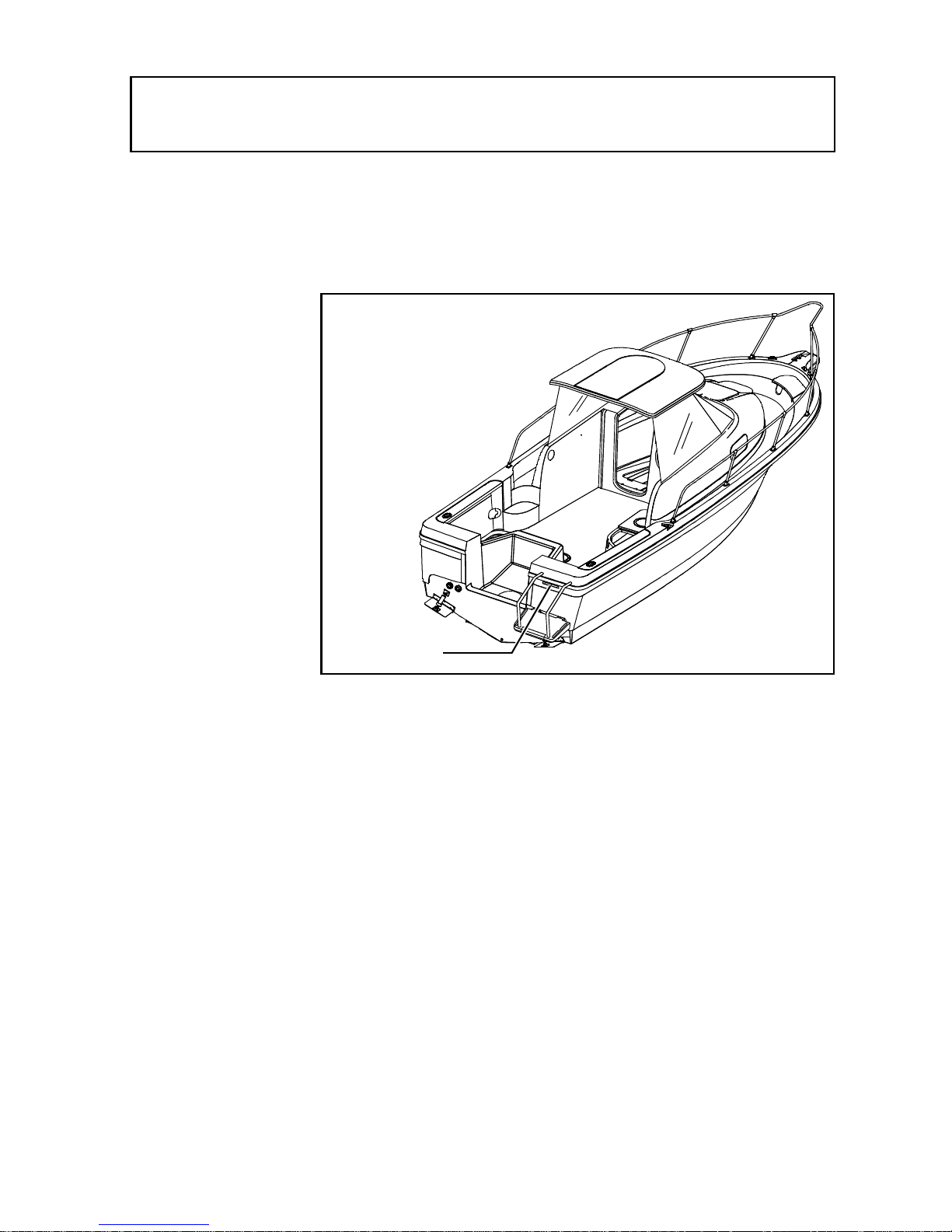
Hull Identification
Number:
The Hull Identification
Number (HIN) is located
on the starboard side of
the transom. Record the
HIN and the engine
serial number in the
space provided above.
Refer to the HIN for any
corresp on de nce or
orders.
HIN LOCATION
(TYPICAL)
© 2001 Bayline r Technical Publicat i ons. All rights r ese rved.
No part of this publication may be reproduced, stored in any retrieval system, or transmitted in
any form by any means, electronic, mechanical, photocopying, recording or otherwise, without
prior written permission of Bayliner.
Printed in the United States of America.
General Notes
The material in this document is for information only and is subject to change without notice.
While reasonable efforts have been made in the preparation of this document to as sure its accuracy, Bayliner assumes no liability resulting from errors or omissions in this document, or from
the use of information cont ained herein. Due to our commitment to product improvement, Bayliner reserves the ri ght to make changes in the pr oduct design, specifications, and equipment at
any time without notice or obligation. Illustrations and/or photos may show optional equipment.
All Bayliner products meet or exceed USCG and/ or NMMA construction standard a. Manufactured with 1,1,1 Trichloroethane, a substance which harms public health and environment during
the manufacturin g pr ocess by destroying ozone in the upper atmosphere.
Proprietary Ri ghts
This document discloses subject matter in which Bayliner has proprietary rights. The information
and design disclosed herein were originated by and are the property of Bayliner. Neither receipt
nor possession thereof confers or transfers any right to reproduce, copy, alter or disclose the document or any part thereof, any information contained therin, or to construct boats or any item from
it, except by written permission from or written agreement with Bayliner.
This document is to be returned upon request to Bayliner.
Page 4

CONTENTS
CHAPTER 1: ABOUT THIS MANUAL
1
1
2
2
3
3
4
5
Dealer Service
Boating Experience
Engine & Accessories Guidelines
Qualified Maintenance
Special Care For Moored Boats
Safety Standards
Hazard Warning Symbols
Carbon Monoxide (CO)
5Sources of CO
6 Carbon Monoxide Alarm System
6 What To Do If Carbon Monoxide Is Detected
CHAPTER 2: PRODUCT SPECIFICATIONS
7
Specifications
CHAPTER 3: COMPONENTS/SYSTEMS
8
Electrical System
9 12-Volt DC System- Fuses, Circuit Breakers and Switches
10 Shore Power/110 Volt AC System
12
12
13
13
13
14
15
16
17
18
Controls
12 Trim Tabs
Navigation and Interior Lights
Compass
Depth Find er
Anchoring
Fuel System
14 Fuel Fills and Vents
14 Fuel Filters
Bilge Blower (2052 FD)
Quick Oil Drain System (2052 FD)
Fire Port System (2052 FD)
Bilge Pump
19 Autofloat Swit ch
Page 5

20 Fresh Water System
21 Marine Head With Pump-out
21 Portable Toilet
22 Bait Well System
23 Alcohol Stove
24 Canvas Top Installations
24 Center Console Models
25 Bowrider Models
26 Cuddy Cabin Models
CHAPTER 4: DRAWINGS & DIAGRAMS
27 1700 (FT)
28 1703 (FS)
29 1802 (FJ)
30 1900 (FG)
31 1903 (FE)
32 2002 (FF)
34 2052 (FD)
36 2503 (FM)
38 2509 (FW)
42 2802 (FH)
CHAPTER 4: WIRING DIAGRAMS
47 Shore Power
48 Single Engine (Outboard), Typical
49 Twin Engine (Outboard), Typical
50 Stern Drive, Typical
LIMITED WARRANTY
51 What Is Not Covered
51 Other Limitations
51 Your Obligation
Page 6

Page 7

1
CHAPTER 1: ABOUT THIS MANUAL
This Owner’s Manual Supplement provides specific information about your boat
that is not covered in the Owner’s Manua l. Stud y the Owner’s Manual and this sup-
plement carefully. Pay particular attention to, APPENDIX A: BAYLINER LIMITED WARRANTY in this suppleme n t. Keep the Owner’s Manual and this
supplement on your boat in a secure, yet readily available place.
Dealer Service
Make sure you receive a full explanation of all systems from the selling dealer
before taking delivery of your boat. Your selling dealer is your key to service. If
you experience any problems with your new boat, immediately contact the selling
dealer. If for any reason your selling dealer is unable to help, you can call us direct
on our customer service hotline: 360-435-8957 or send us a FAX: 360-403-4235.
A Bayliner replacement parts catalog is available online at:
http://www.baylinerparts.com. Replacement parts can be purchased from any
authorized Bayliner dealer.
Boating Experi ence
If this is your first boat or if you are chang in g to a type of bo at you are no t familiar
with, for your own comfort and safety, you must obtain handling and operating
experience before assuming command of the boat.
Take one of the boating safety classes offered by the U.S. Power Squadrons or the
U.S. Coast Guard Auxiliary. For more course information, including dates and
locations of upcoming classes, contact the organizations directly:
U.S. Power Squadrons: 1-888-FOR-USPS (1-888-367-8777) or on the Internet
•
at: http://www.usps.org
U.S. Coast Guard Auxiliary: 1-800-368-5647 or on the Internet at:
•
http://www.cgaux.org
Outside the United States, your selling dealer, national sailing federation or local
yacht club can advise you of local sea schools or competent instructors.
WARNING!
!
CONTROL HAZARD!
times. DO NOT use you r boat w hile und er t he in fluenc e of alc ohol or dr ugs.
A qualified operator must be in control of the boat at all
Trophy Owner’s Manual Supplement
Page 8
2 CHAPTER 1: ABOUT THIS MANUAL
Engine & Accessories Guidelines
Your boat’s engine and accessories were selected to provide optimum performan ce
and service. Installing different engines or other accessories may cause unwanted
handling traits. Should you choo se to install a dif ferent engine or to add a ccessories
that will affect the boat’s running trim, have an experienced marine technician perform a safety inspection and handling test before using your boat again.
Be advised that certain modifications to your boat can result in cancellation of your
warranty protection. Check with your dealer before making any modifications to
your boat.
The engine and accessories installed on your boat come with their own operation
and maintenance manuals. Read and un derstand these manu als before operat ing the
engines and accessories.
NOTICE
When storing your boat please refer to your engine’s op eration and maintenance manuals.
Qualified Maintenance
WARNING!
!
To maintain the integrity and safety of your boat, only qualified people should
perform maintenance on, or in any way modify: The steering system, propulsion sys tem, eng ine con tr o l sys tem , fu el syst em, en vironment al con tr ol s ys tem ,
or elect ric al syst em .
Failure to maintain your boat’s systems as designed could violate the laws in your
jurisdiction and could expose you and other people to the dang er of bodily inju ry or
accidental death. Follow the instructions provided in the Owner’s Manual, this
Owner’s Manual Supplement, the engine owner’s manual and all accessory instru ction sheets/manuals included in your boat’s owner’s packet.
Trophy Owner’s Manual Supplement
Page 9
CHAPTER 1: ABOUT THIS MANUAL 3
Special Care For Moored Boats
If moored in saltwater or fresh water, your boat will collect marine growth on its
hull bottom. This will detract from the boat’s beauty, greatly affect its perfo rmanc e
and may damage the ge l coat. There are two methods of slowing mar i ne growth:
1. Periodically haul the boat out of the water and scrub the hull bottom with a
bristle brush and a solution of soap and water.
2. The hull below the waterline was painted with anti-fouling paint at the factory.
Occasionally you will need to re-paint it with a good grade of anti-fouling paint.
NOTICE
To help seal the hull bottom and reduce the possibility of gelcoat blistering on
moored boats, apply an epoxy barrier coating, such as INTERLUX,
2000E/2001E
Many states regulate the chemical content of bottom paints. Ask your local
dealer about the laws in effect in your area.
. Cover the barrier coating with several coats of anti-fouling paint.
Interprotect
Safety Stan dards
Your boat’s mechanical and electrical systems were designed to meet safety standards in effect at the time it was constructed. Some of these standards were mandated by law. All of them were designed to insure your safety, and the safety of
other people, vessels and property.
In addition to this supplement, read the Owner’s Manual, warning labels, and all liter-
ature in your owner’s packet for impo rtant s afety standar ds and h azard information.
DA N GE R !
!
PERSONAL SAFETY HAZA RD!
parts of the boat not designated for such use.
Sitting on seat backs, lounging on the forward deck, bow riding, gunwale riding
or occupying the transom platform or the aft sunlounge cushions while underway is especially hazardous and WILL cause personal injury or death.
DA N GE R !
!
PERSONAL SAFETY HAZARD! Always
objects before getting un derway. The anchor and other items that are not
properly secured can come loose when the boat is moving and cause personal
injury or death.
secure the anchor and other loose
DANGER
DO NOT allow anyon e to rid e on
DANGER
Trophy Owner’s Manual Supplement
Page 10
4 CHAPTER 1: ABOUT THIS MANUAL
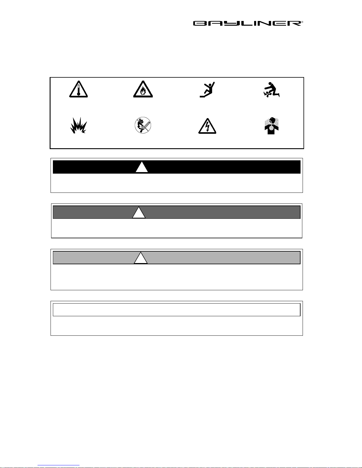
Hazard Warning Symbols
The hazard warning symbols shown below are used throughout this supplement to
call attention to potentially dangerous situations that could lead to either personal
injury or product damage. Read these warnings and follow all safety instructions.
HOT
HAZARD!
EXPLOSION
HAZARD!
FIRE
HAZARD!
OPEN FLAME
HAZARD!
!
PERSONAL INJURY
& FALLING HAZARD!
ELECTRICAL
HAZARD!
DANGER!
ROTATING
PROPELLER HAZARD!
CO POISONING
HAZARD!
This message box alerts you to immediate hazards which WILL cause severe
personal injury or death if the warning is ignored.
WARNING!
!
This message box alerts you to hazards or unsafe practices which COULD
result in severe personal injury or death if the warning is ignored.
CAUTION!
!
This message box alerts you to hazards or unsafe practices which COULD
result in minor personal injury or cause product or property damage if the
warning is i gnor e d.
This message box calls attention to installation, operation or maintenance information, which is important to proper operation but is not hazard related.
Trophy Owner’s Manual Supplement
NOTICE
Page 11
CHAPTER 1: ABOUT THIS MANUAL 5
Carbon Monoxide (CO)
DANGER!
!
CARBON MONOXIDE POISONING HAZARD!
gas (CO) is colorless, odorless, and extremely dangerous. All
engines, generator s, and fuel bu rning ap pliance s pr oduc e CO as
exhaust. Dir e ct and pr olonge d exposu r e to CO will ca use BR AIN
DAMAGE or DEA TH. Signs of CO poisoning i nclude headache,
nausea, dizz ine ss, and d r owsin ess. Sour ce s of CO in cl ude:
CO poisoning causes a significant number of boating deaths each year. Called the
"silent killer", CO is an extremely toxic, colorless, odorless and tasteless gas .
Breathing CO blocks the ability of your blood to carry oxygen. The effects are
cumulative, even low levels of exposure can result in injury or death.
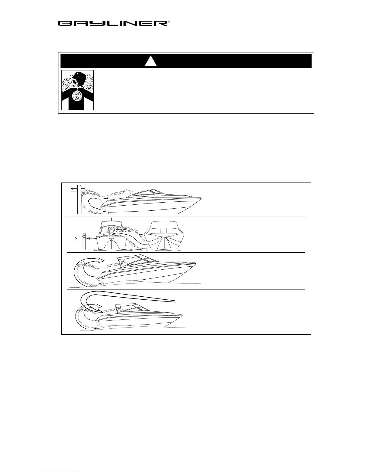
Sources of CO
Sources of CO include:
a. Using the eng ine or generato r
when the boat is moor ed in a
confined space.
Carbon monoxide
b. Mooring close to another boat that
is running its e ngine, generato r , or
any other CO source.
c. Running the boat with the trim
angle of the bow too high.
d. Running the boat without through
ventilation (station wagon effect).
To correct stationary situations a and/ or b:
Close all windows, portlights and hatches.
•
If possible, move your boat away from the source of the CO.
•
To correct runnin g situations c and/or d:
Trim the bow down.
•
Open windows and canvas.
•
When possible, run the boat so that the prevailing winds will help dissipate the
•
exhaust.
IMMEDIATELY take corrective action when CO is detected (see,
Monoxide Alarm System
, on the next page).
Carbon
Trophy Owner’s Manual Supplement
Page 12
6 CHAPTER 1: ABOUT THIS MANUAL
Factors increasing the effects of CO include:
• Age.
• Smokers or people exposed to high concentrations of cigarette smoke.
• Consumption of alcohol.
• Lung disorders, heart problems, and pregnancy.
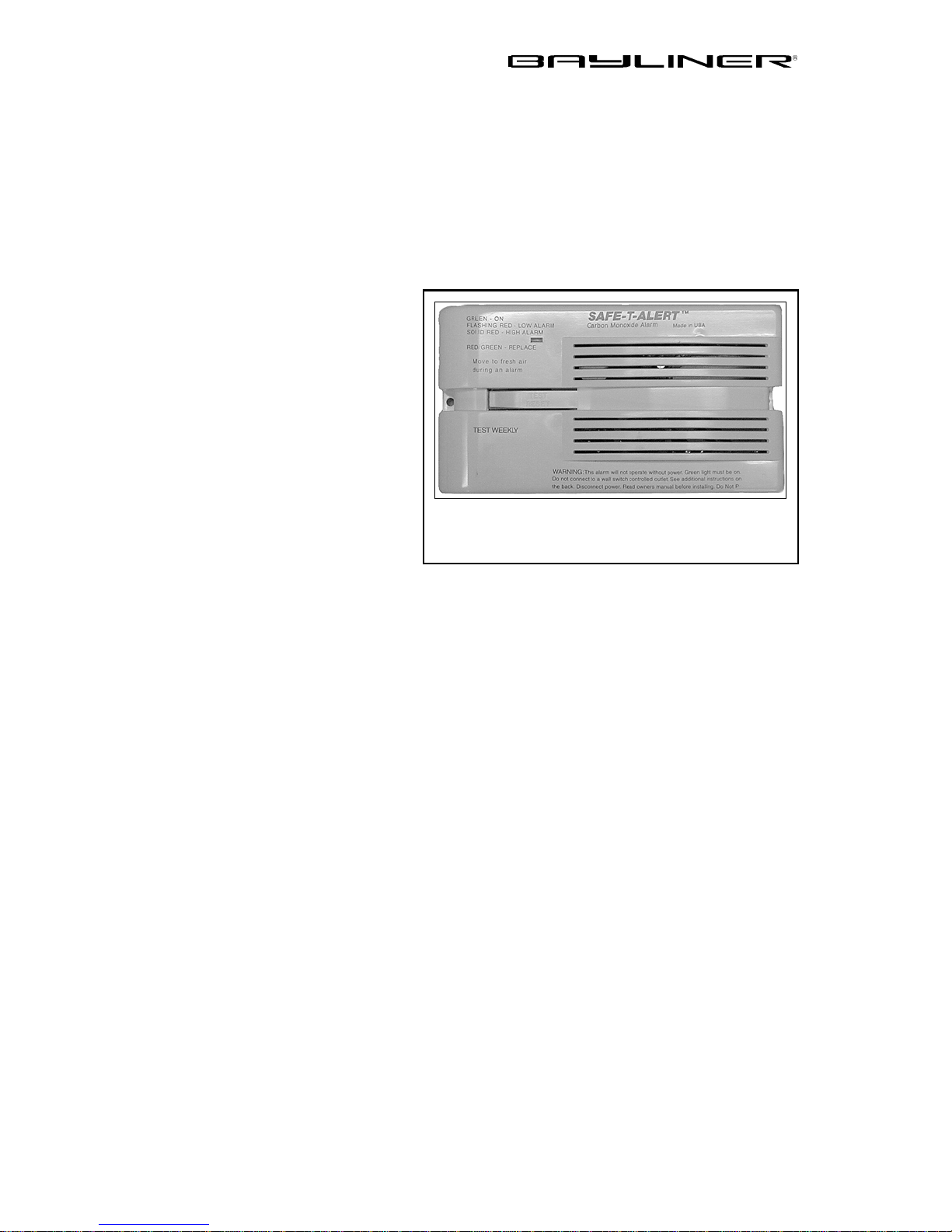
Carbon Monoxide Alarm System
Your boat may feature a carbon
monoxide (CO) al arm sys tem.
DO
NOT DISCONNECT THE
ALARM SYSTEM.
Read and
understand the manufacturer’s
instructions for your CO alarm
system. If you did not receive an
instruction manual, call (800) 3830269 and one will be mailed to
you. If your boat is not equipped
with a carbon monoxide alarm,
consider purchasing one from your
MARINE TECHNOLOGIES INC.
CARBON MONOXIDE ALARM MODEL 60-541
(REPLACE AFTER TEN YEARS OF USE)
dealer or marine supply store.
What To Do If Carbon Monoxide Is Detected
• Immediately ven tilate any enclosed spaces that are occupied b y people and reset
your CO alarm.
• Immediately move anyone showing any symptoms of CO poisoning into fresh
air. See a doctor if any symptoms persist. If the person is unconscious, immediately administer oxygen or CPR and call for emergency help.
Trophy Owner’s Manual Supplement
Page 13

CHAPTER 2: PRODUCT SPECIFICATIONS
Bridge Clearance With
Hard Top or T-Top (Option)
Specifications
Model Description
1700 (FT) Trophy Dual Console
Overall Length
17’ 0” 4’ 3” N/A 7’ 2” 2’ 7” 37 N/A N/A
Bridge Clearance
Beam
Maximum Draft
Fuel Tank
7
ater Tank
Capacity (gal)
apacity (gal)
Holding Tank
Capacity (gal)
1703 (FS) Trophy Center Console
1802 (FJ) Trophy Cuddy
1900 (FG) Trophy Dual Console
1903 (FE) Trophy Center Console
2002 (FF) Trophy Walkaround
2052 (FD) Trophy Walkaround
2503 (FM) Trophy Center Console
2509 (FW) Trophy Cuddy
2802 (FH) Trophy Cuddy
17’ 0” 4’ 9” N/A 7’ 2” 2’ 5” 37 N/A N/A
18’ 0” 5’ 2” N/A 7’ 6” 2’ 7” 52 N/A N/A
19’ 0” 4’ 3” N/A 8’ 2” 2’ 9” 55 N/A N/A
19’ 0” 5’ 10” 7’ 9” 8’ 2” 2’ 8” 55 N/A N/A
21’ 7” 5’ 7” 7’ 4” 8’ 1” 2’ 9” 85 N/A N/A
21’ 7” 5’ 6” 7’ 3” 8’ 1” 2’ 9” 65 N/A N/A
27’ 3” 6’ 2” 7’ 11” 8’ 5” 2’ 9 150 N/A N/A
27’ 3” 6’ 7” 8’ 1” 8’ 5” 2’ 5” 147 8 N/A
31’ 0” 7’ 5” 9’ 6” 9’ 9” 2’ 6” 240 30 30
Trophy Owner’s Manual Supplement
Page 14
8
CHAPTER 3: COMPONENTS/SYSTEMS
Electrical System
Thoroughly read and understand this section, the electrical sections of the Owner’s
Manual
schematics are provided at the back of this supplement.
• NEVER install knife switches or other arcing devices in fuel compartments.
• NEVER substitute automotive parts for marine parts. Electrical, ignition and
• Ensure all of the battery switches are in the OFF position before performing
• DO NOT modify the electrical systems or relevant drawings.
• Only qualified personnel should install batteries and/ or perform maintenance
and all accessory manuals included in your boat’s owner’s packet. Wiring
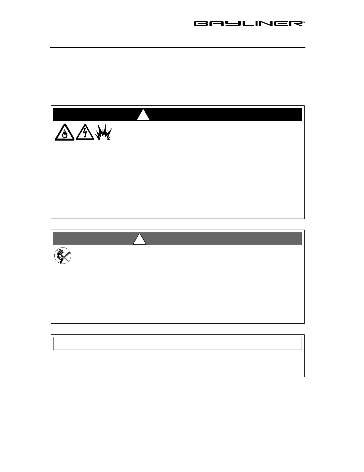
DANGER!
!
EXTREME FIRE, ELECTRIC SHOCK
and EXPLOSION HAZARD!
To mi nimi ze t he ri sks of fi r e, elec tr ic sho ck and exp los ion:
fuel system parts were designed and manufactured to comply with rules and
regulations that mini mize risk s of fire and explosio n.
any work in the engine spaces.
on the electrical system.
WARNING!
!
FIRE & EXPLOSION HAZARD!
• Fuel fumes are heavier than air and will collect in the bilge areas where they
can be accident ly igni ted. V i sually an d by smel l (sn iff tes t), c heck t he engin e
and fuel compartments for fumes or accumulation of fuel. Always use the
bilge blowers for at least four minutes prior to engine starting, electrical system maintenance or activation of electrical devices.
• Minimize the dange r of fir e an d explos ion by not exp osi ng batteri es to open
flame or sparks. NEVER allow smoking anywhere near the batteries.
NOTICE
Electric al c onn ect ion s ar e pr on e to c orr o sio n. To reduce corr os ion caus ed el ec trical problems, keep all electrical connections clean and apply a spray-on protectant that is designed to protect connections from corrosion.
Trophy Owner’s Manual Supplement
Page 15
CHAPTER 3: COMPONENTS/SYSTEMS 9
CAUTION!
!
SHOCK & ELECTRICAL SYSTEM D AMAGE HA ZARD !
• NEVER disconnect the battery cables while the engine is running since dam-
age may occur to your boat’s electrical system components.
• The parallel switch should be turned on only in emergencies.
• The battery charging systems (alternators and battery charger) are designed
to charge lead-acid batteries. Before installing gel-cell or other new technology batteries, read and follow the battery charger’s operating instructions.
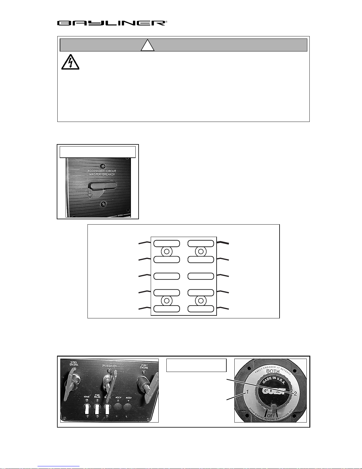
12-Vo lt DC System- Fuses, Ci rcuit Breakers and Switches
TYPICAL ACCESSORY
CIRCUIT MASTER BREAKER
DEPTH FINDER
(OPTION), RED WIRE
BLANK (SPARE 10 amp)
BLOWER (I.O. BOATS
ONL Y), YELLOW WIRE
INSTRUMENTS,
BLUE WIRE
BILGE PUMP,
BROWN WIRE
The engine is protected by a large circuit breaker on
the engine. The accessories on some models are protected by a master circuit breaker usually located near
the battery. In addition, a fuse block for branch accessory circuits is located near the helm panel.
Wires are color-coded to indicate which accessory
each fuse services. Some items, such as radios and
bilge pumps, may be fused individually at the unit.
Autofloat switches are fused at the battery.
FUSE BLOCK (TYPICAL)
10 amp
10 amp
5 amp
10 amp
5 amp
10 amp
15 amp
10 amp
10 amp
10 amp
12v POWER
SUPPLY, RED WIRE
IGNITION SWITCH
(I.O. BOATS ONLY),
RED/PURPLE WIRE
HORN, BROWN/
GREEN WIRE
NAVIGATION/ANCHOR
LIGHTS, BLUE WIRE
STEREO, RED WIRE
Some models are equipped with b attery switches. Your Owner’s Manual prov ides a
general descripti on of battery s witch fun ction in the Batteries portion of the Electrical Section.
TYPICAL
BATTERY SWITCHES
STBD BATTERY
PORT (OR ONLY)
BATTERY
Trophy Owner’s Manual Supplement
Page 16
10 CHAPTER 3: COMPONENTS/SYSTEMS
Shore Power/110 Volt AC System
DANGER!
!
FIRE, ELECTRIC SHOCK
and EXPLOSION HAZARD!
To mi nimi ze t he ri sks of fi r e, elec tr ic sho ck and exp los ion:
• DO NOT alter shore power connectors and use only compatible connectors.
• Before connecting or disconnecting the shore power cord to your boat, make
sure all breakers and switches on the AC master panel are turned OFF .
• To prevent shock or injury from an accidental dropping of the “hot” cord
into the water , ALWAYS attach the shore power cord to the boat inlet first;
then to the dockside connection. When disconnecting from shore power, disconnect the shore power cord from the dockside connection first.
• NEVER leave a shore power cord connected to the dockside connection only .
• Only use shore power cords approved for marine use. NEVER use ordinary
indoor or outdoor extension cords that are not rated for marine use.
CAUTION!
!
SHOCK & ELECTRICAL SYSTEM D AMAGE HAZAR D!
• Monitor the polarity indicator lights EVERY TIME you connect to
shore power.
• When connec ting to shore power and you encounter a reversed polarity
light (RED colored), DO NOT energize the main breaker switches.
Instead, IMMEDIATELY disconnect the shore power cord (ALWAYS
from the dockside receptacle first) and notify marina management.
WARNING!
!
SHOCK & ELECTRICAL SYSTEM DAMAG E HA ZARD!
• Periodically check the shore power cord(s) for deterioration or damage. Damaged or faulty cords should NEVER be used since the danger of fire and electrical shock exists.
• DO NOT pinch shore pow er cords in doors or hatches, or coi l the shore power
cord too tightly since these situations can generate enough heat to result in
a fire.
• If a shore power cord should accidently become immersed in water , THOROUGHLY dry the blades and contact slots before reusi ng.
Some dockside installation s ma y be rated less th an 30 amps , therefore, you
may need to purchase lower amp adapters. Whenever a lower amp adapter is
used, however, ther e will be a corresponding drop in supplied power from the
dockside system.
Trophy Owner’s Manual Supplement
NOTICE
Page 17
CHAPTER 3: COMPONENTS/SYSTEMS 11
CAUTION!
!
SHOCK & ELECTRICAL SYSTEM D AMAGE HAZAR D!
• NEVER connect dockside power to your boat outside North America
unless you ha ve pu rchased the interna t io nal electri c al co nve r si o n op t io n.
• The simultaneous use of several AC components can result in an overloaded circuit. It may be necessary t o turn off on e or more accessories in
order to use another accessory.
• Use double insulated or three-wire protected electrical appliances whenever po ssible .
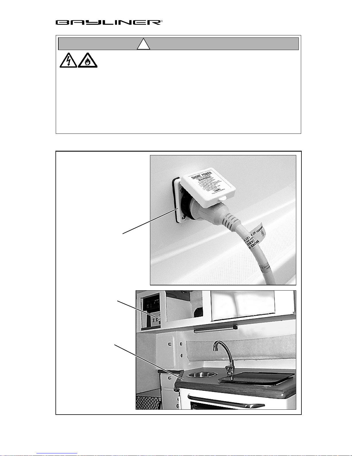
SHORE POWER INLE T
110 VOLT AC PANEL
GALLEY AREA
Trophy Owner’s Manual Supplement
Page 18
12 CHAPTER 3: COMPONENTS/SYSTEMS
Controls
Read and understand the Controls section of both the Owner’s Manual and engine
manual, provided in the owner’s packet, for instructions and warranty information.
Trim Tabs
WARNING!
!
LOSS OF CONTROL HAZARD!
Improper use of trim tabs will cause loss of control!
Do not
•
Do not
•
unsafe handling characteristics.
Do not
•
allow anyone unfamiliar with trim tabs to use them.
use trim tabs in a following sea as they will cause broaching or other
use trim tabs to co mpen sate for excessi ve une qual w eight distr ibution .
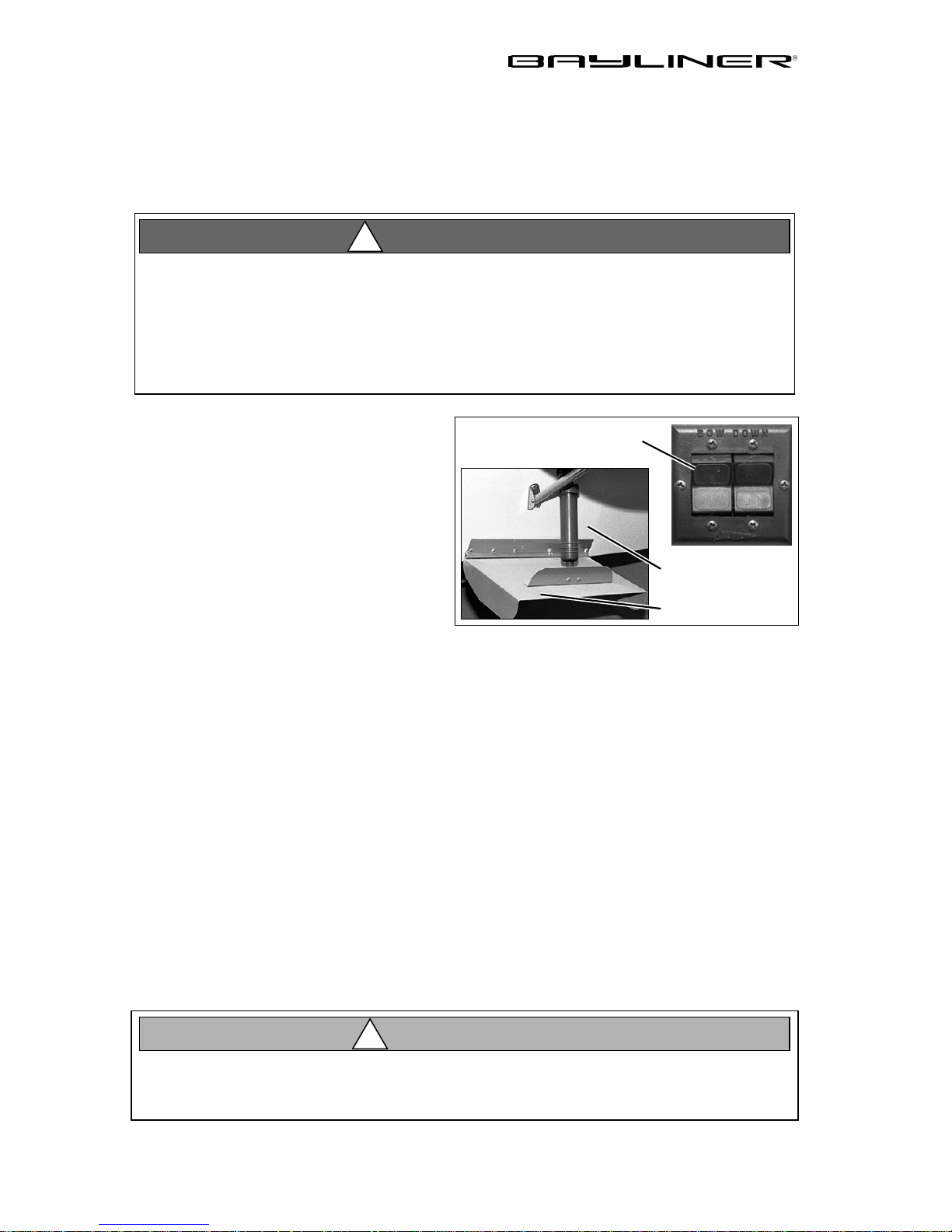
The trim tabs may be used to help keep
your boat level at cruising speeds.
The trim tabs are controlled by two
rocker switches at each helm station.
Before using the trim tab rocker
switches, read and understand the trim
tab operation manual included in your
yacht’s owner’s packet.
When cruising speed is reached:
The port or starboard trim switch may be used (one at a time) to level the boat.
•
Perform trim tab adjustment with several short touches to the switch rather than
•
one long one.
After each short touch allow several seconds for the hull to react.
•
TYPICAL TRIM TAB
ROCKER SWITCHES
TRANSOM
TYPICAL TRIM TAB
Navigation and Interior Lights
Read the navigation light section of the Owner’s Manual. The na v iga tion an d
interior lights supplied with your boat are of top quality, but you should be aware
that failure may periodically occur for a variety of reasons:
There may be a blown fuse -
•
The bulb may be burned out -
•
A wire may be damaged or may have come loose -
•
The bulb base may b e corroded -
•
electrical lubricant.
• Conserve battery power . Pr olonged operation of cabin interior lights (overnight) will r es ult in a dr aine d battery.
• A void the storage of gear where it would bl ock navigation lights fr om view.
Trophy Owner’s Manual Supplement
replace the fuse in the switch panel.
carry spare b u lbs for replacement.
repair as required
clean the base and coat it wi th non-con ductive
CAUTION!
!
.
Page 19

CHAPTER 3: COMPONENTS/SYSTEMS 13
Compass
Your boat may come equipped with a compass. Carefully read and follow the manufacturer’s calibration and operating instructions provided in the owner’s packet.
Depth Finder
Your boat may come equipped with a depth finder. It will provide you with measurements of water depth beneath the boat and i n many cases it may help y ou locate
schools of fish. The depth finder comes with its own manual. We suggest that you
read it carefully before using the unit.
WARNING!
!
DO NOT use the depth finder as a navigational aid to prevent collision, gr ounding, boat damage or personal injury . When the boat is moving, submerged
objects will not be se en until t hey ar e already under t he boat. Bot tom dept hs
may change too quickly to allow time for the boat operator to react. If you suspect shallow water or submerged objects, run the boat at very slow speeds.
Anchoring
Read and understand the Anchoring section of the Owner’s Manual.
WARNING!
!
FIRE/EXP LOS IO N HAZ AR D
DO NOT open the engine cover until the fire is extinguished.
Trophy Owner’s Manual Supplement
Page 20
14 CHAPTER 3: COMPONENTS/SYSTEMS
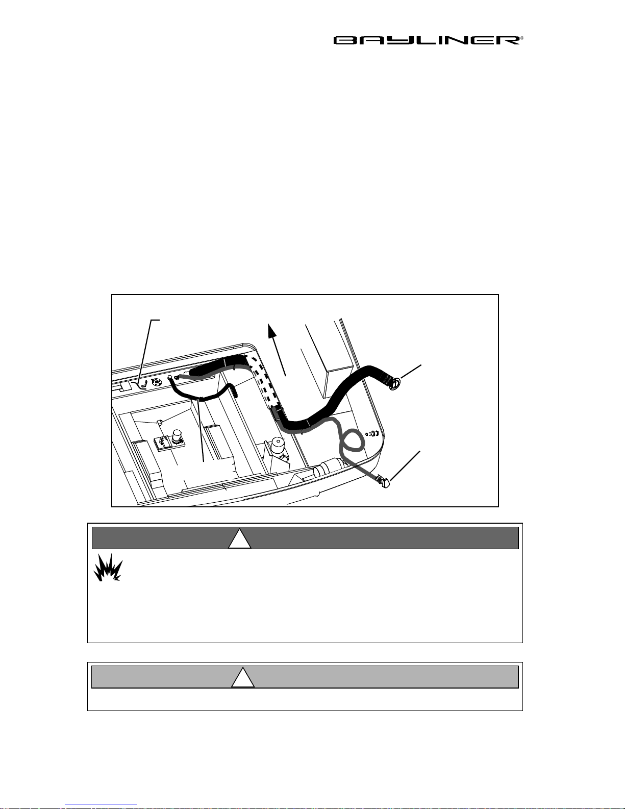
Fuel System
Fuel Fills and Vents
Fuel fills are located either on the aft deck or on the side decks adjacent to the aft
cockpit. Fuel receptacle caps are marked “GAS”. Fuel vents are normally located in
the hull or transom below and in the same general area as the fill. If you have
trouble filling the fuel tank, check to see that the fuel fill and vent lines are free of
obstructions and kinks.
Fuel Filters
Fuel filters should be replaced periodically to ensure that they remain clean and
free of debris. A fine mesh screen filter is located on the fuel pickup tube. An additional filter, when supplied by the engine manufacturer, is installed on the engine.
Consult your selling dealer or local marina concerning fuel additives that help to
prevent fungus or buildup in your fuel tanks.
TYPICAL FUEL SYSTEM
FUEL TANK
DECK FITTING
FUEL FILL
FWD
FUEL TANK
VENT
FUEL FEED
HOSE
WARNING!
!
FIRE/EXPLOSION HAZARD
It is very important that the fuel system be inspected thoroughly the first
time it is filled and then at each subsequent filling . For your safet y and t he
safety of your passengers, the fueling instructions in the
Owner’s Manual
must be followed.
Avoid the storage or handling of gear near the fuel lines, fittings and tank.
Trophy Owner’s Manual Supplement
CAUTION!
!
Page 21
CHAPTER 3: COMPONENTS/SYSTEMS 15
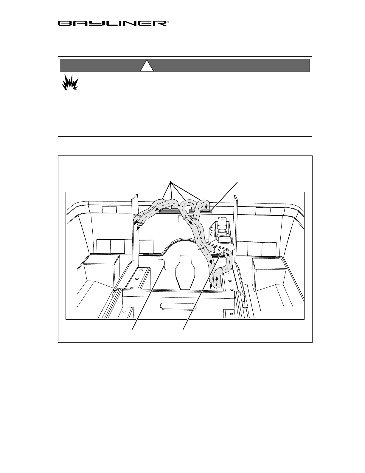
Bilge Blower (2052 FD)
WARNING!
!
FIRE/EXPLOSION HAZARD
Operation of the blower system is NOT A GUARANTEE that ex plosive fumes
have been removed. If you smell any fuel, DO NOT start the engine.
If the engine is already running, immediately shut off the engine and all electrical accessories. Investigate immediately . DO NOT obstruct or modify the ventilation system.
BLOWER SYSTEM & AIRFLOW DIRECTION
COLLECTION BOXVENTILATION HOSES
The bilge blower removes fumes from the engine compar tment and dr aws fr esh air
into the compartment through the deck vents.
To ensure fresh air circulation, use the bilge blower for at least four minutes
before starting the engine, during starting, and while running the boat below
cruising speed.
BLOWERTRANSOM
Trophy Owner’s Manual Supplement
Page 22
16 CHAPTER 3: COMPONENTS/SYSTEMS
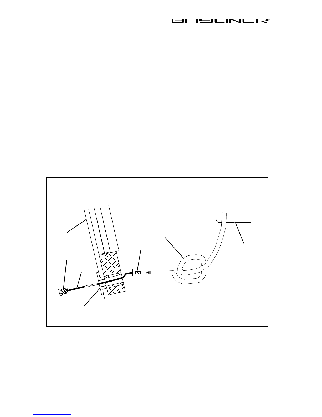
Quick Oil Drain System (2052 FD)
All stern drive models are equipped with a quick oil drain system.
To drain the engine oil:
1. Remove the boat from the wat er.
2. Unscrew the garboard drain plug.
3. Pull the draw cord until the oil drain plug and the oil drain hose slide out of the
garboard drain.
4. Place the end of the oil drain hose into a suitable container.
5. Unscrew the oil drain plug and drain the engine oil.
6. Replace the oil drain plug.
7. Push the drain hose back into the bilge.
8. Replace the garboard drain plug.
Always dispose of waste oil in accordance with local regulations.
TRANSOM
GARBOARD
DRAIN PLUG
DRAW
CORD
GARBOARD
DRAIN
QUICK OIL DRAIN SYSTEM
OIL DRAIN HOSE
OIL DRAIN PLUG
BILGE
ENGINE OIL PAN
Trophy Owner’s Manual Supplement
Page 23
CHAPTER 3: COMPONENTS/SYSTEMS 17
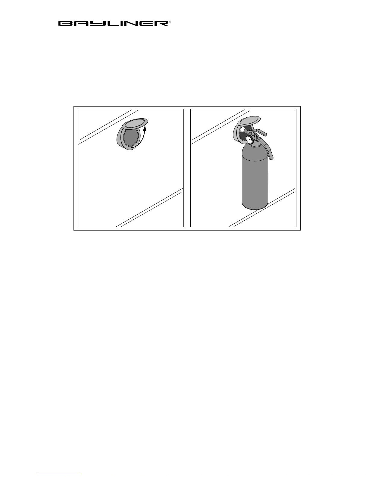
Fire Port System (2052 FD)
Stern drive models have a Fire Port located on the motor box.
In the event of an engine fire:
1. Lift the fire port cover.
2. Discharge a Class B fire extinguisher into the engine co mpartmen t thr oug h th e
fire port.
1. 2.
Trophy Owner’s Manual Supplement
Page 24
18 CHAPTER 3: COMPONENTS/SYSTEMS
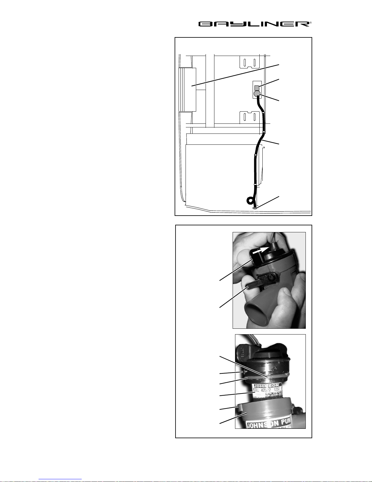
Bilge Pump
Your boat has one impeller-type bilge
pump. The bilge pump is automatically controlled by a float switch (see
"Autofloat Switch" on the next page).
The bilge pump can also be controlled by a switch on the dash.
Check the bilge pump often to make
sure it is working properly. To check
the bilge pump:
Turn on the dash-mounted switch
•
and make sure that water in the
bilge is pumped overboard.
If bilge water is present and the pump
motor is running but not pumping:
Inspect the bilge pump hose for a
•
kink or collapsed area.
If the bilge pump hose is not the problem, check the bilge pump housing
for clogging debris:
TYPICAL BILGE PUMP SYSTEM
TRANSOM
FLOAT
SWITCH
BILGE
PUMP
HOSE
THRUHULL
Bilge Pump Cleaning:
To remove the power cartridge:
1. Lift the tab while rotating the
fins counterclockwise.
2. Lift out the power cartridge.
3. Clear t he outer housing of
debris.
To reinstall the power cartridge:
1. Make sure the “O” ring is properly seated.
2. Coat the “O” ring with a light
film of vegetable or mineral oil.
3. Align the two cams on either
side of the power cartridge with
the two s lots on the o uter housing and press the power cartridge into the housing while
twisting clockwise.
4. To ensure proper reinstallation
of the power cartridge, attempt
to twist the fins counterclockwise without lifting the tab: The
cartridge should stay in place.
BILGE PUMP
COMPONENTS
FIN
TAB
LIGHT FILM
OF OIL
CAM
(TYPICAL)
“O” RING
POWER
CARTRIDGE
SLOT
(TYPICAL)
OUTER
HOUSING
Trophy Owner’s Manual Supplement
Page 25
CHAPTER 3: COMPONENTS/SYSTEMS 19
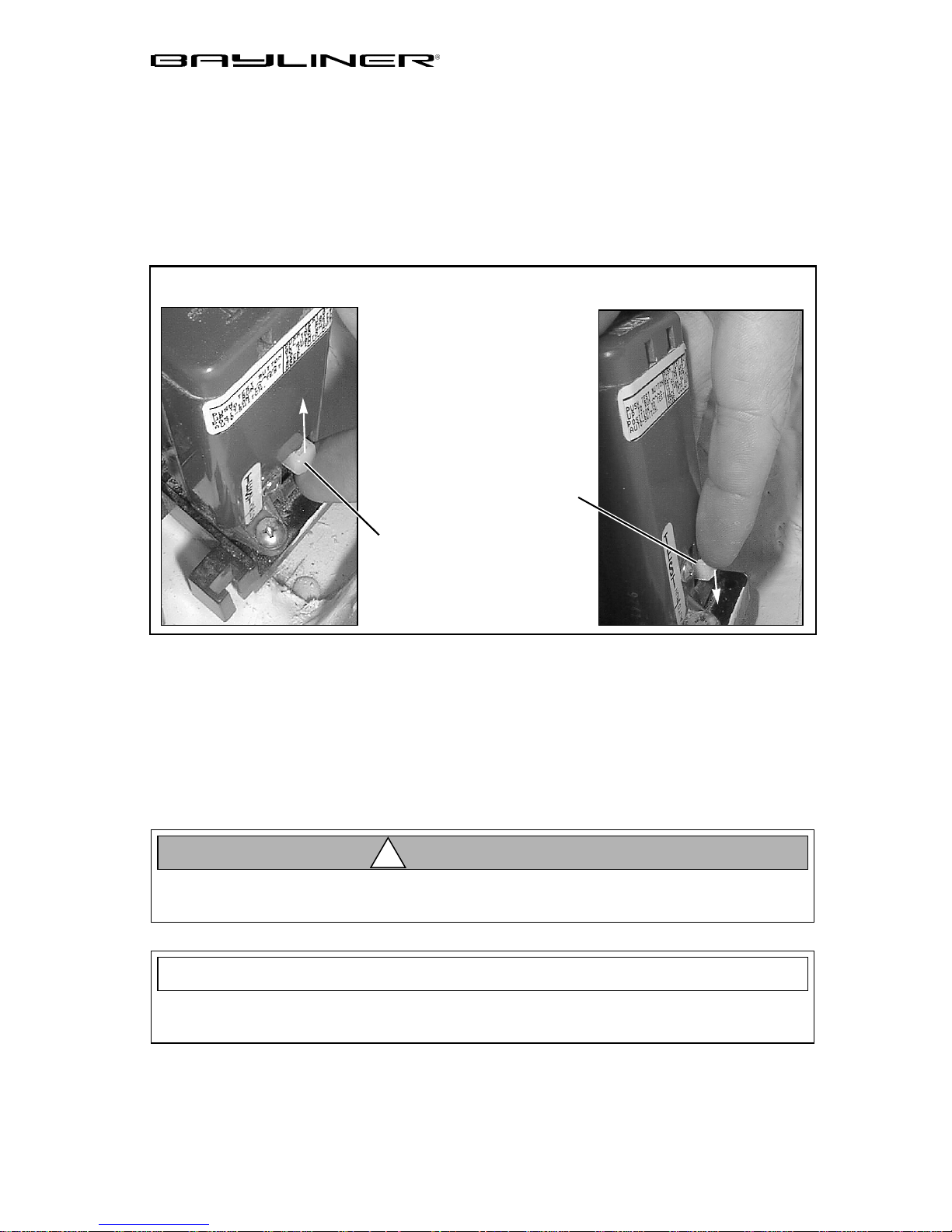
Autofloat Switch
An electromagnetic float (autofloat) switch autom a tically turns on the bilge pump
whenever bilge water rises above a preset level. An autofloat switch is mounted
next to the bilge pump. The autofloat switch is wired directly to the battery and will
normally function even when the boat is completely shut down and left unattended.
Test the autofloat switch often as follows:
Float Switch Test:
FLOAT SWITCH TEST BUTTON
DOWN - AUTO POSITION
UP - TEST POSITION
1. Lift the float switch test button to turn on the bilge p ump.
2. If the pump does not turn on, check the inline fuse. If the fuse is good but the
switch doesn’t work, it may indicate a bad switch or possibly a low battery.
3. Push the test button all the way back down to auto mode.
CAUTION!
!
When test is completed on a float switch, you must push the test button all the
way down to the auto position to turn the switch back to auto mode!
NOTICE
Discharge of oil, oil waste or fuel into navigable waters is prohibited by law . V iolators are subject to legal action by the local authorities.
Trophy Owner’s Manual Supplement
Page 26
20 CHAPTER 3: COMPONENTS/SYSTEMS
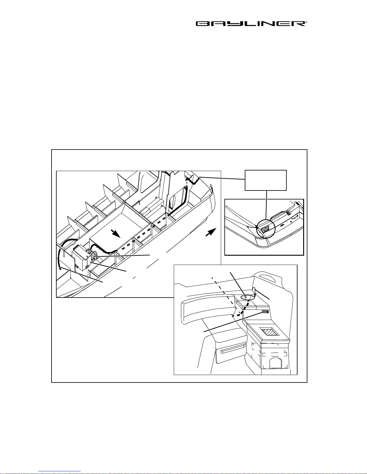
Fresh Water System
Fresh water systems are available on some models. These pressure-type (demand)
systems operate when the water pump switch (located near the sink in the cuddy
cabin) is in the ON position. Turn the pump switch OFF when the boat is not in use
and when the water tank is empty.
Stored water can become stagnant and distasteful. Pump the water tank dry before
leaving your boat unattended for long periods of time. Occasionally you may want
to disinfect your water system. Ask your selling dealer about available treatments
and procedures.
Your boat may be equipped with a transom shower. Please read and f ollow the manufacturer’s operating instructions supplied in your owner’s packet.
TYPICAL FRESH WATER SYSTEM COMPONENTS
TO TRANSOM
SHOWER ON
AFT DECK
P
O
R
T
WATER TANK
TO SINK F AUCET
WATER PUMP
WATER
SWITCH
& LABEL
DRAIN
HOSE
PUMP
T
F
A
SINK
FAUCET
Trophy Owner’s Manual Supplement
Page 27
CHAPTER 3: COMPONENTS/SYSTEMS 21
Marine Head With Pump-out
If your boat features a marine head and pump out system, carefully read the manufacturer’s owner’s manual supplied in your owner’s packet.
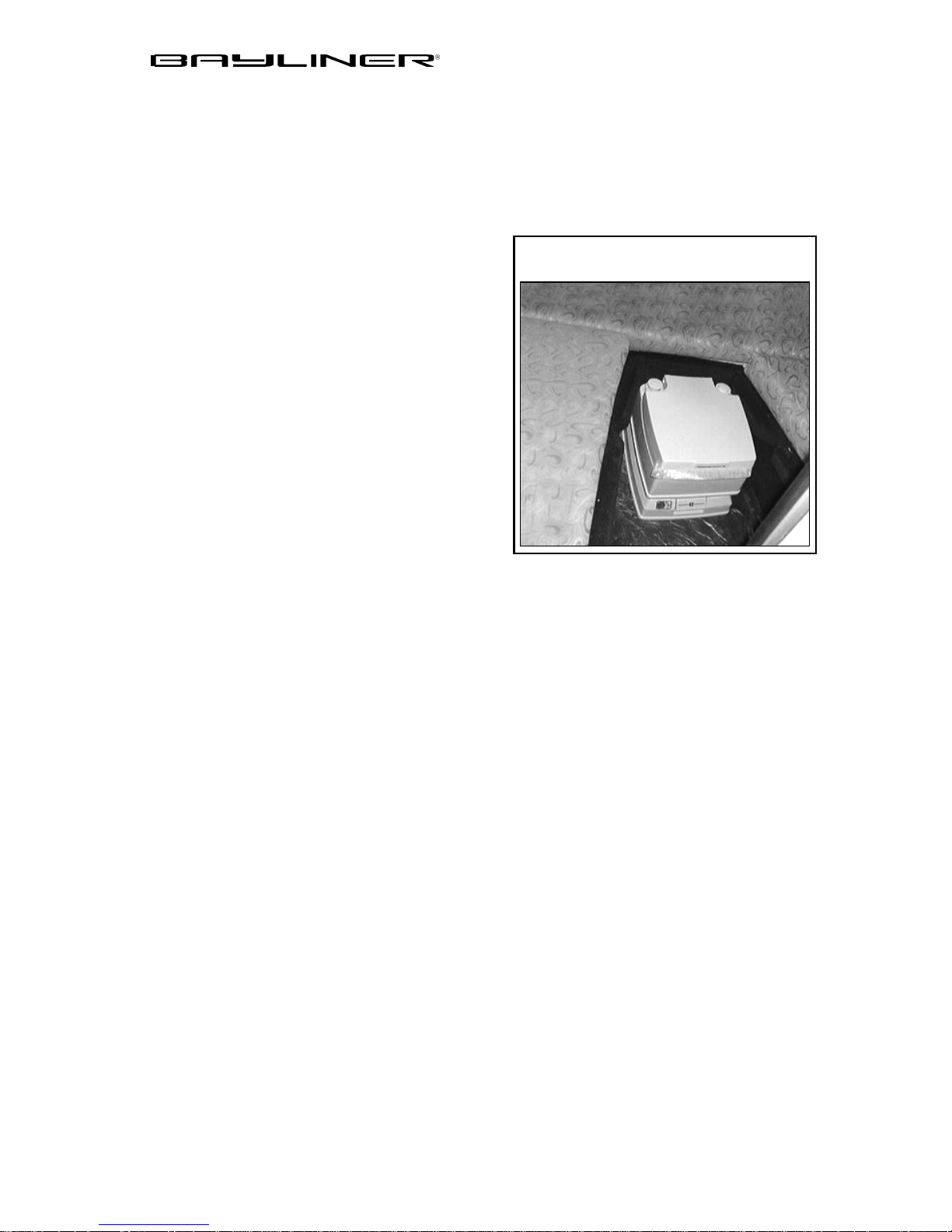
Portable Toilet
Your boat may feature a portable toilet.
Read and follow the manufacturer’s operat-
ing instructions supplied in yo ur owner’s
packet before using your portable toilet.
PORTABLE TOILET STORAGE
LOCATION (TYPICAL)
Trophy Owner’s Manual Supplement
Page 28
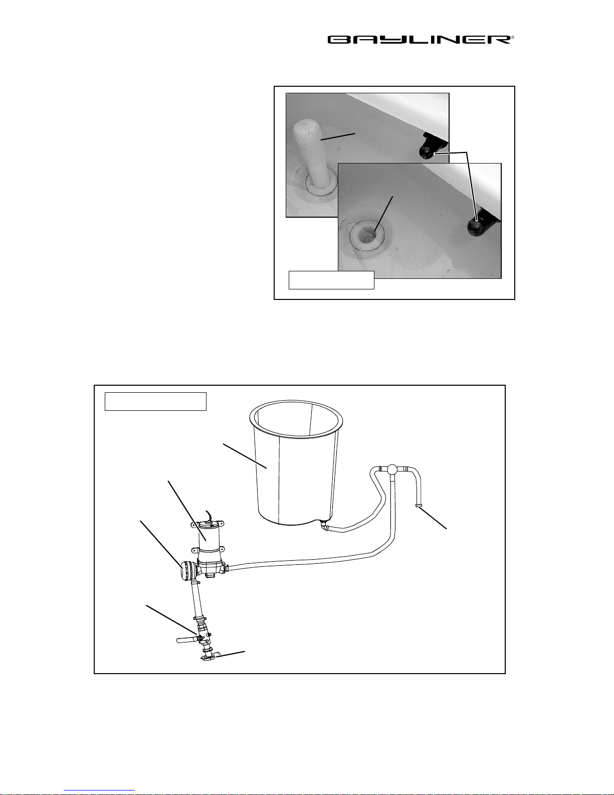
22 CHAPTER 3: COMPONENTS/SYSTEMS
Bait Well System
Your boat may feature a bait well.
A typical bait well system features
A hi-speed pickup located on
•
the underside of the hull.
A seacock valve is attached to
•
the pickup. The seacock allo ws
for immediate shutdown
if needed.
A water pump. This pump is
•
normally located in the bilge
area or possibly higher in a
storage area.
BAIT WELL
STAND PIPE
DRAIN
REMOVE STAND PIPE
TO COMPLETELY
DRAIN BAIT WELL
AERATOR
VALVE
The water continues from the
pump to the aerator valve and into
TYPICAL BAIT WELL
DRAIN SYSTEM
the bait well. On some models,
water is also directed to the raw
water wash down from this system. Typically, bait wells have an overflow stand
pipe and a full drain sy stem. The ba it well sw itch is on or near th e main dash panel .
The water pump will pump a constant flow of water into the bait well when the seacock is open and the switch is on.
TYPICAL BAIT WELL
SYSTEM COMPONENTS
BAIT WELL
WATER PUMP
WATER FILTER
TO RAW WATER
WASH DOWN
SEACOCK
Trophy Owner’s Manual Supplement
HI-SPEED PICKUP
Page 29
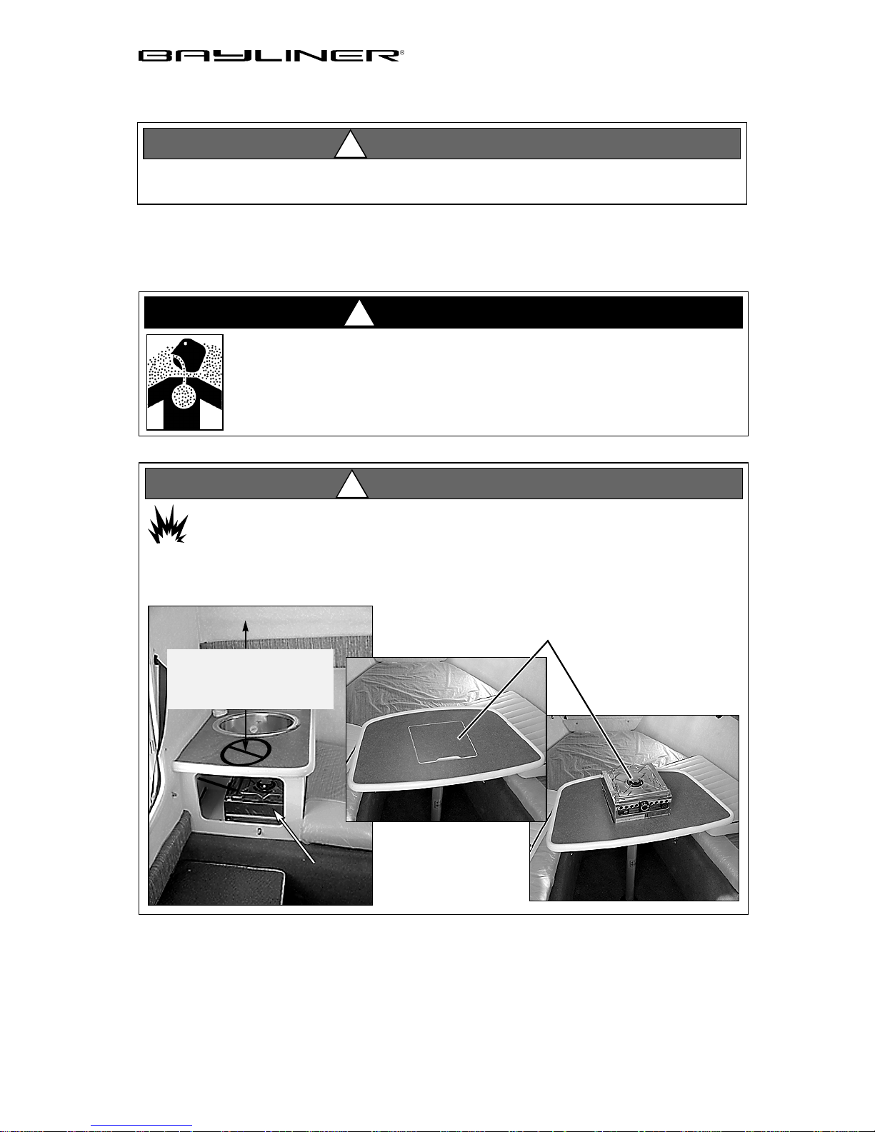
CHAPTER 3: COMPONENTS/SYSTEMS 23
Alcohol Stove
WARNING!
!
Reduce the possibility of fire by removing all combustible materials away fr om
the stove before/during use.
If your boat features a single burner alcohol stove, carefully read and follow the
manufacturer’s operating instru cti ons su pplied i n your owner’s packet before using
your stove for the first time.
DANGER!
!
CARBON MONOXIDE POISONING HAZARD!
The alcohol stove is a potential source of dangerous
carbon monoxide gas (CO). Do not us e witho ut ad equate ven tilation.
WARNING!
!
FIRE/EXPLOSION HAZARD
FIRE HAZARD.
The portable stove must be placed in the design ated operat-
ing location when in use (see photos bel ow) .
NEVER USE STOVE ON
THIS COUNTER TOP!
PROXIMITY TO OVERHEAD
IS A FIRE HAZARD.
STOVE
STORAGE
AREA
CORRECT LOCATION OF
STOVE DURING USE
Trophy Owner’s Manual Supplement
Page 30
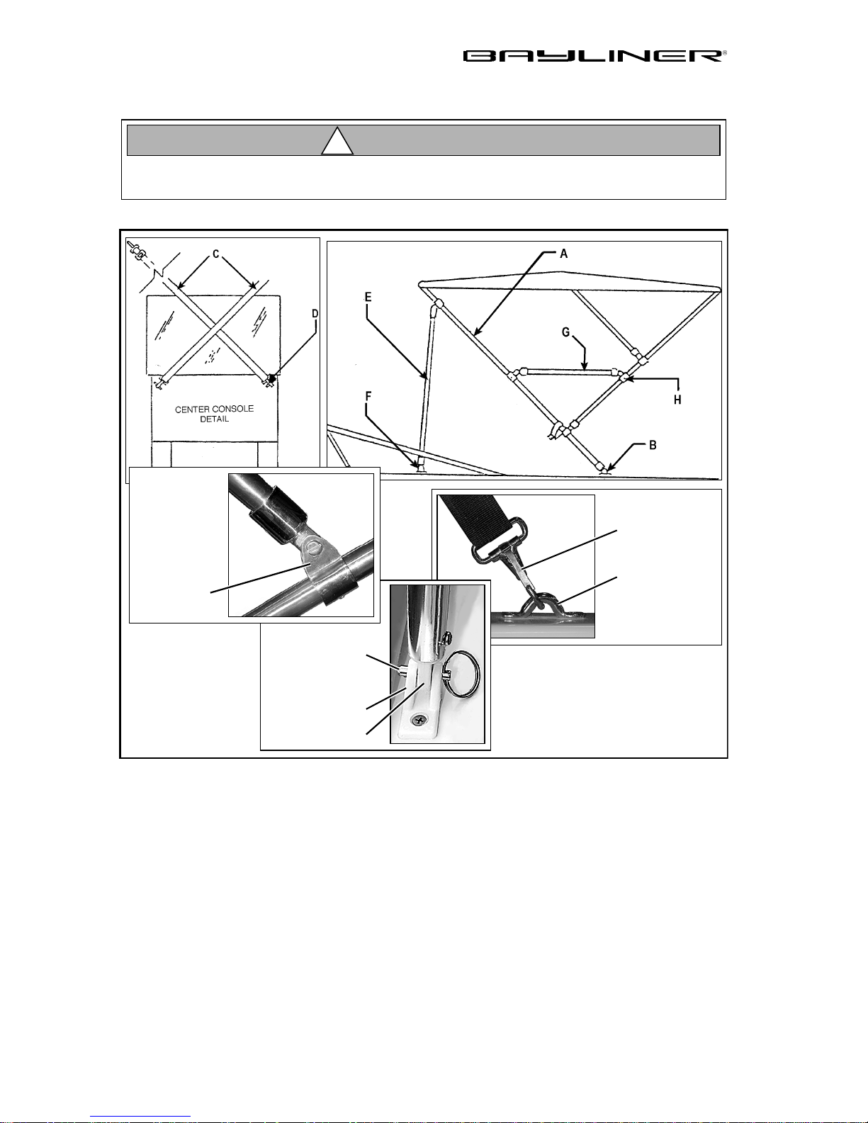
24 CHAPTER 3: COMPONENTS/SYSTEMS
Canvas Top Insta llation s
CAUTION!
!
Take down and securely stow the convertible top, side curtains and back cover
before transporting your boat by road.
Center Console Models
HOLD DOWN
STRAP HOOK
DECK EYELET
JAW SLIDE
SECURING PIN
DECK HINGE
END EYE
1. Slide the end eyes of the main bow (A) into the aft deck hinges (B) and insert
the securing pins.
2. Connect the hold down straps (C) to the deck eyelets (D).
1. Slide the end eyes of the forward braces (E) into the forward deck hinges (F)
and insert the securing pins.
1. Attach the side braces (G) to the quick release jaw slides on the secondary b ow
(H) and in sert the securing pins .
2. Adjust the jaw slides, if needed, to obtain a tight bimini top. Tighten the set
screws to hold the bimini in place.
3. Tighten the hold down straps (C) at the forward end of the bimini top.
Trophy Owner’s Manual Supplement
Page 31
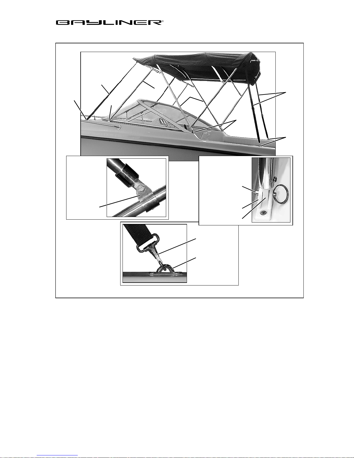
Bowrider Models
E
F
CHAPTER 3: COMPONENTS/SYSTEMS 25
C
D
A
B
SECURING PIN
G
H
JAW SLIDE
DECK HINGE
END EYE
HOLD DOWN
STRAP HOOK
DECK EYELET
1. Slide the end eyes of the main bow (A) into the aft deck hinges (B) and insert
the securing pins.
2. Slide the end eyes of the forward supports (C) into the forward deck h inges (D)
and insert the securing pins.
3. Attach the hooks of the forward hold down straps (E) to the forward deck eyelets (F) and tighten the straps.
4. Attach the hooks of the aft hold down s traps (G) to the aft deck eyelets (H) an d
tighten the straps.
5. No adjustments to the jaw slides should be needed as they are preset during
manufacturing. Before attempting to adjust the jawslide po sitio ns, obtain the
correct measurements from you selling dealer.
Trophy Owner’s Manual Supplement
Page 32
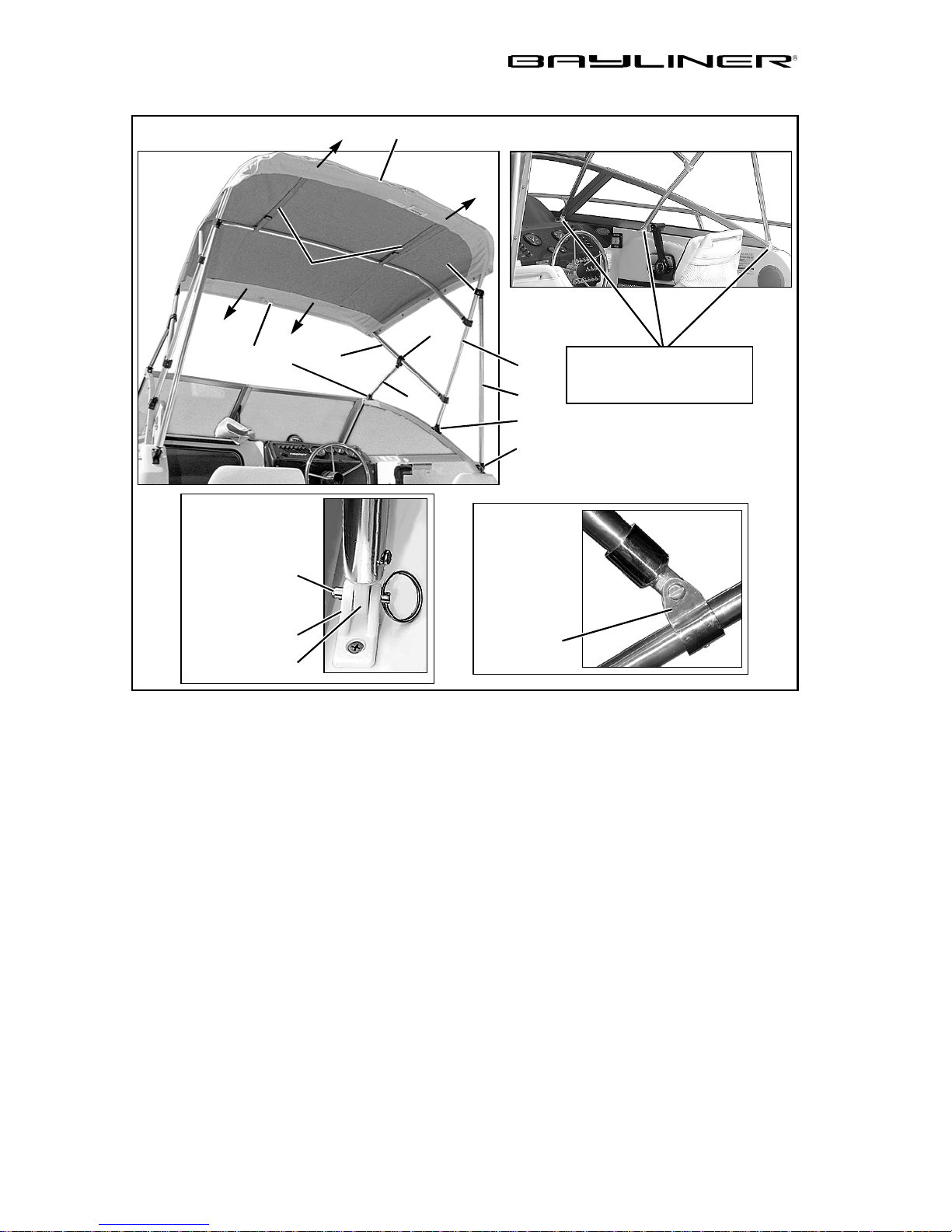
26 CHAPTER 3: COMPONENTS/SYSTEMS
Cuddy Cab i n Models
H
I
L
K
J
E
D
C
A
F
B
G
NOTE:
SOME HINGES MAY BE
LOCATED ON DECK
SECURING PIN
DECK HINGE
END EYE
JAW SLIDE
1. Slide the end eyes of the main bow (A) into the mid deck hinges ( B) and secure
with the pins.
2. Attach the forward braces (C) to the secondary bow (D).
3. Slide the end eyes of the forward braces into the forward deck hinges (E) and
secure with the pins.
4. Attach the aft braces (F) to the main bow (A).
5. Slide the end eyes of the aft braces into the aft deck hing es (G) and secure with
the pins.
6. Make the canvas taut by pulling aft and do wn o n th e aft ed ge ( H) of the b imini
top while securing the aft brace jaw slide (I). Also pull forward and down on
the forward edge (J) of the bimini top while securing the forward brace jaw
slide (K).
7. Tighten the top straps (L), if needed, by adjusting the buckle slides.
8. Additional canvas (i.e. side curtains, slant back cover or camper cover) should
be secured to the top canvas before final adjustment. Like the top, the additional canvas should be smooth and taut.
Trophy Owner’s Manual Supplement
Page 33
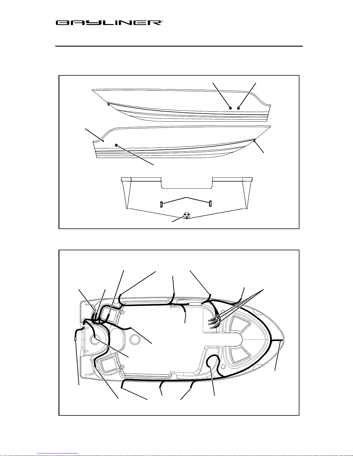
CHAPTER 4: DRAWINGS & DIAGRAMS
1700 (FT)
Hull Exterior View
27
BILGE PUMP
OVERBOARD
Deck Wire Routing
PORT HULLSIDE
STARBOARD HULLSIDE
DECK DRAIN
GARBOARD DRAIN
BAIT WELL DRAIN
TRANSOM
STERN EYES
DECK DRAIN
BOW EYE
GROUNDING
BLOCK
ENGINE
HARNESS
GROUND
TO BATTERY
STERN
LIGHT
LIVE WELL
PUMP
VIEW IS UNDERSIDE OF DECK
SPEAKERS
SHIFTER
FUEL TANK
SENDER
BILGE
PUMP
SPEAKERS
HORN
TO DASH
BOW
LIGHT
STEREO
Trophy Owner’s Manual Supplement
Page 34
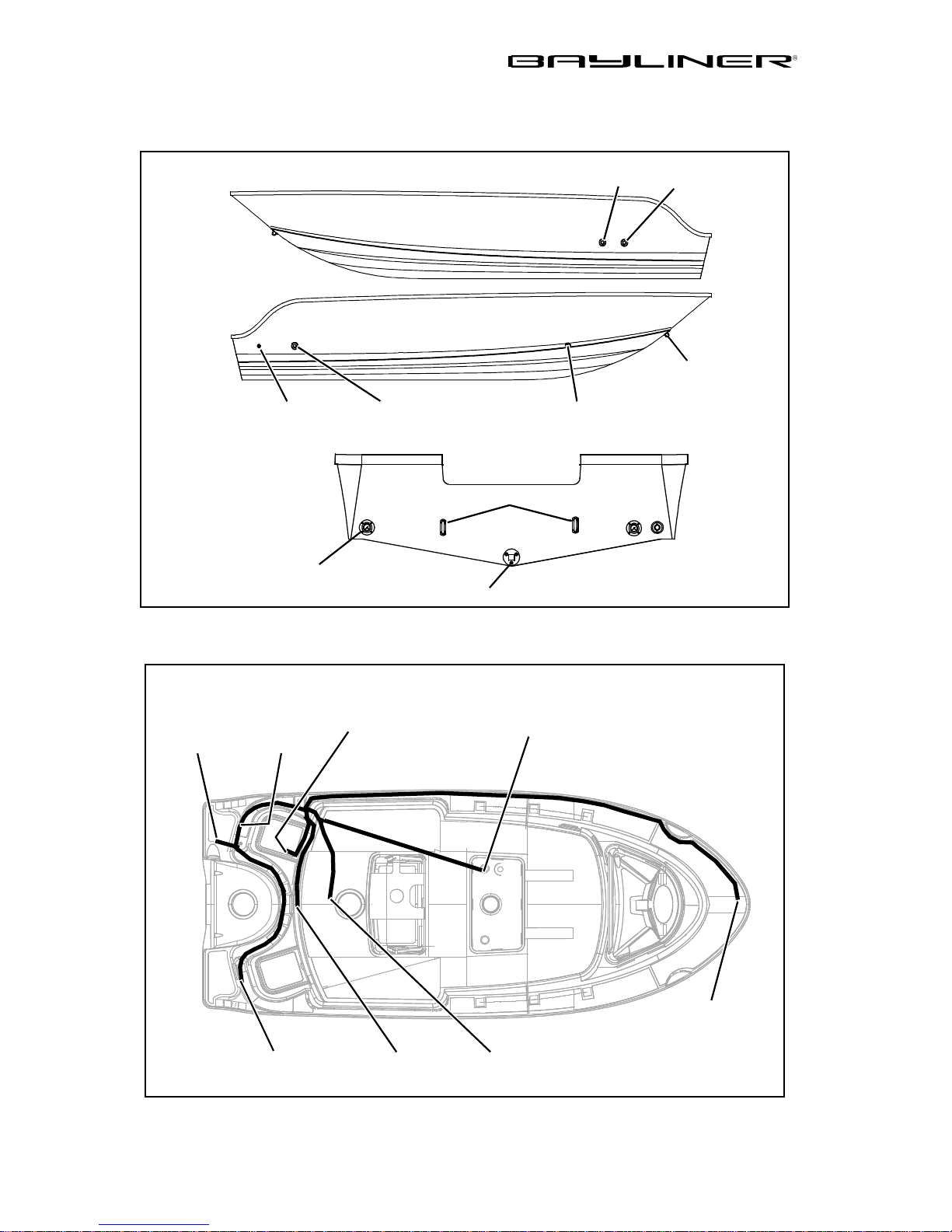
28 CHAPTER 4: DRAWINGS & DIAGRAMS
1703 (FS)
Hull Exterior View
PORT HULLSIDE
STARBOARD HULLSIDE
BAIT WELL
DRAIN
DECK
DRAIN
BOW EYE
BILGE PU M P
OVERBOARD
SCUPPER, TYPICAL
PORT & STBD
Deck Wire Routing
ANCHOR
LIGHT
GROUNDING
BLOCK
DECK
DRAIN
TRANSOM
STERN EYES
GARBOARD DRAIN
VIEW IS UNDERSIDE OF DECK
BATTERY
SWITCH
TO DASH
STORAGE
DRAIN
LIVE WE LL
PUMP
Trophy Owner’s Manual Supplement
BILGE
BOW LIGHT
FUEL TANK
SENDER
Page 35
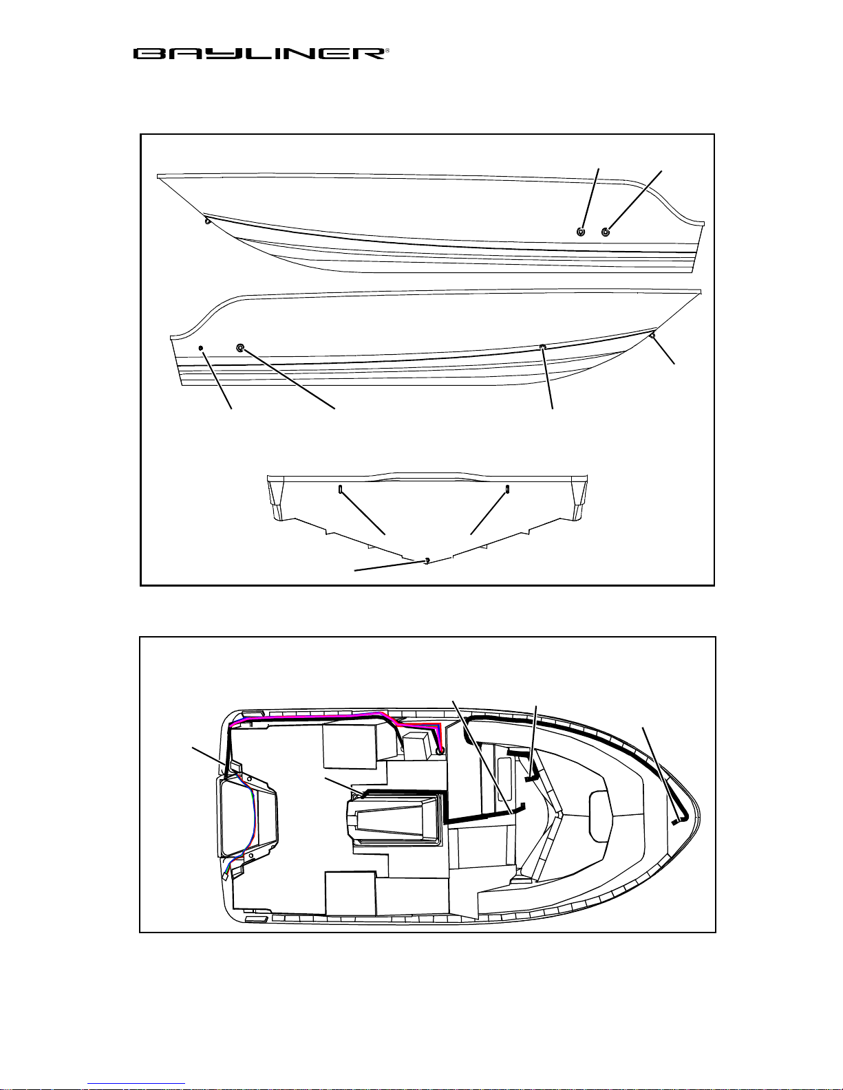
1802 (FJ)
Hull Exterior Hardware
CHAPTER 4: DRAWINGS & DIAGRAMS 29
PORT HULLSIDE
STARBOARD HULLSIDE
BAIT WELL
DRAIN
DECK
DRAIN
BOW EYE
BILGE PUMP
OVERBOARD
GARBOARD DRAIN
Electrical Harness
STERN
LIGHT
SUMP
DECK
DRAIN
TRANSOM
STERN EYES
VIEW IS UNDERSIDE OF DECK
DOME
LIGHT
STORAGE
DRAIN
WIPER
(OPTION)
BOW
LIGHT
Trophy Owner’s Manual Supplement
Page 36
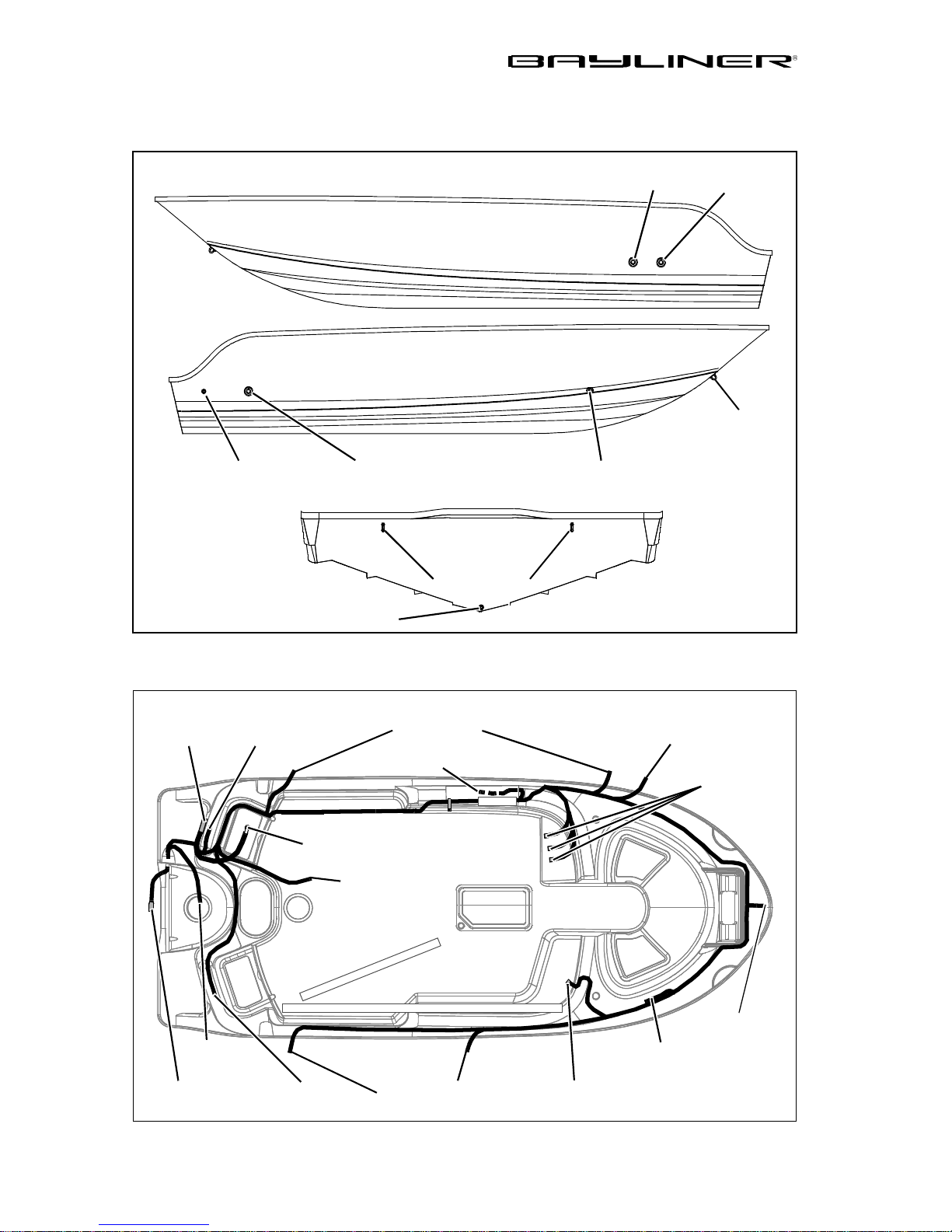
30 CHAPTER 4: DRAWINGS & DIAGRAMS
1900 (FG)
Hull Exterior Hardware
PORT HULLSIDE
STARBOARD HULLSIDE
BAIT WELL
DRAIN
DECK
DRAIN
BOW EYE
BILGE PUMP
OVERBOARD
GARBOARD DRAIN
Wire Harness Routing
GROUND
BLOCK
STERN
LIGHT
DECK
DRAIN
UNDERSIDE OF DECK
SPEAKERS
SHIFTER
GROUND
TO BATTERY
FUEL TANK
SENDER
TRANSOM
STERN EYES
STORAGE
DRAIN
HORN
TO DASH
BILGE
PUMP
ENGINE
HARNESS
PUMP
Trophy Owner’s Manual Supplement
BOW
EXTRA
SPEAKER
WIRE
SPEAKERSLIVE WE LL
STEREO
LIGHT
Page 37
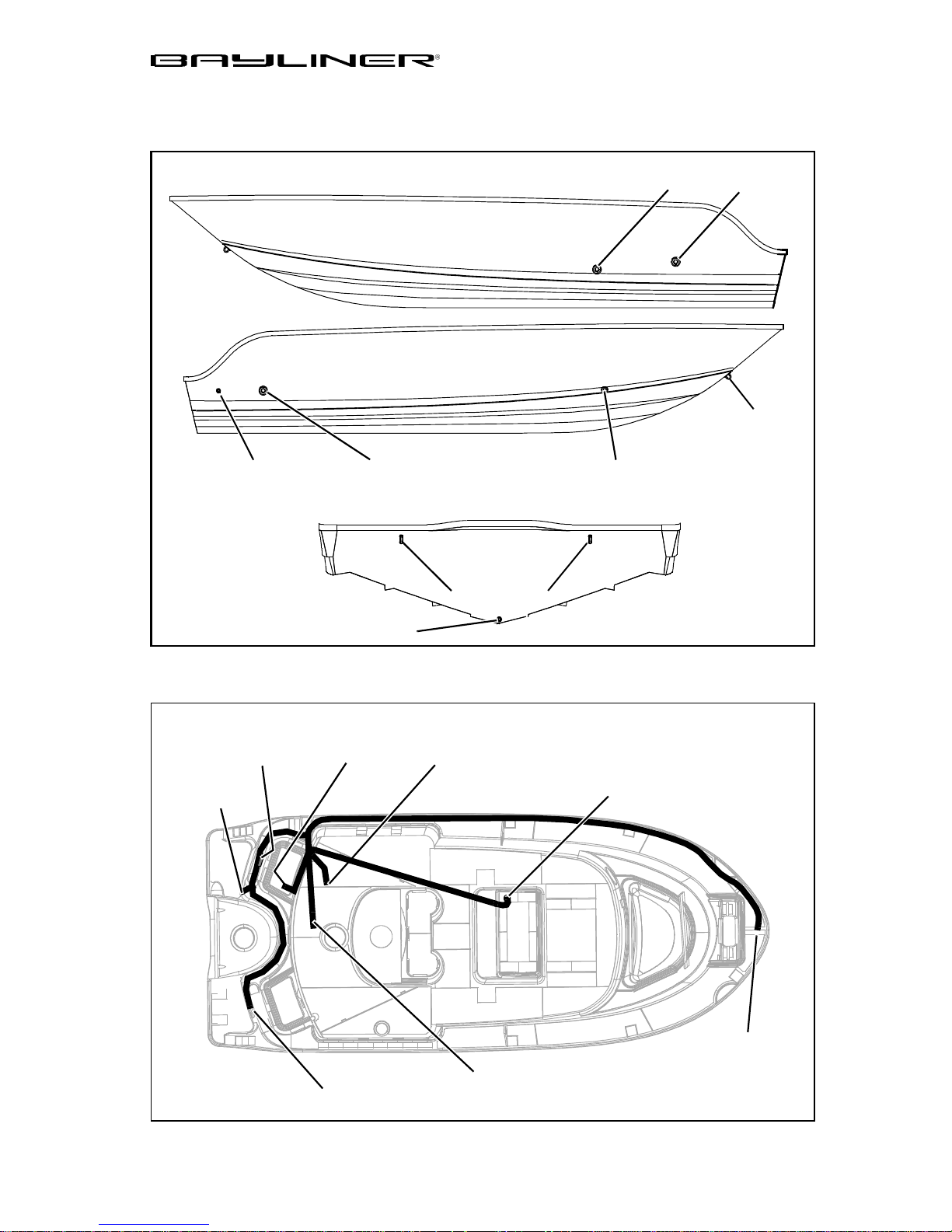
1903 (FE)
Hull Exterior Hardware
CHAPTER 4: DRAWINGS & DIAGRAMS 31
PORT HULLSIDE
STARBOARD HULLSIDE
BAIT WELL
DRAIN
DECK
DRAIN
BOW EYE
BILGE PUMP
OVERBOARD
GARBOARD DRAIN
Wire Harness Routing
GROUNDING
BLOCK
ANCHOR
LIGHT
TO BATTERY
DECK
DRAIN
SWITCH
STORAGE
DRAIN
TRANSOM
STERN EYES
UNDERSIDE OF DECK
BILGE
PUMP
TO DASH
LIVE WELL
PUMP
BOW
LIGHT
FUEL TANK
SENDER
Trophy Owner’s Manual Supplement
Page 38
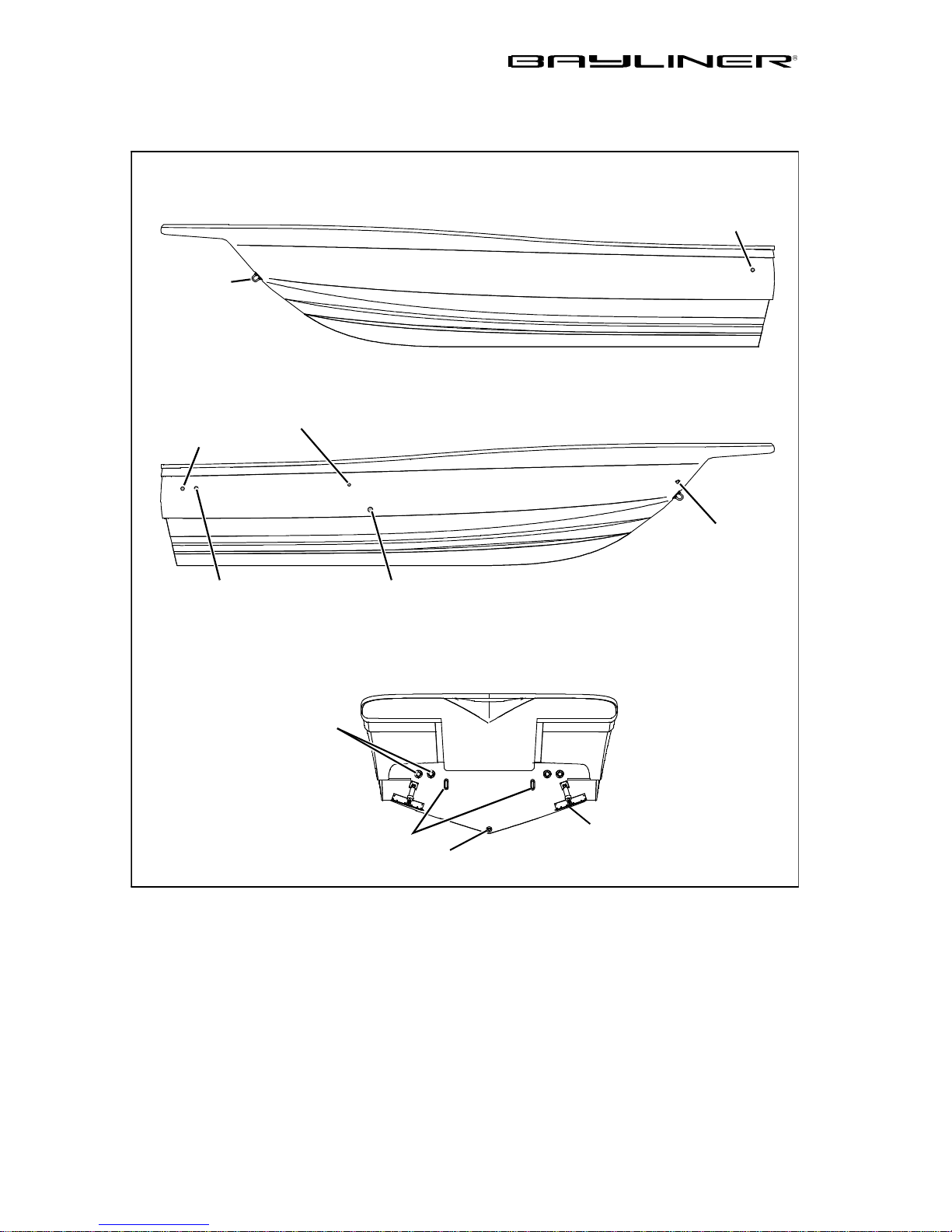
32 CHAPTER 4: DRAWINGS & DIAGRAMS
2002 (FF)
Hull Exterior Hardware
FISH WELL
DRAIN
BOW EYE
FISH WELL
DRAIN
BILGE PU M P
OVERBOARD
(TYPICAL PORT/STBD)
FUEL
VENT
DECK DRAINS
PORT HULLSIDE
STARBOARD HULLSIDE
ROPE
LOCKER
DRAIN
LIVE WELL
DRAIN
STERN EYES
GARBOARD DRAIN
Trophy Owner’s Manual Supplement
TRANSOM
TRIM TAB
(TYPICAL PORT/STBD)
Page 39
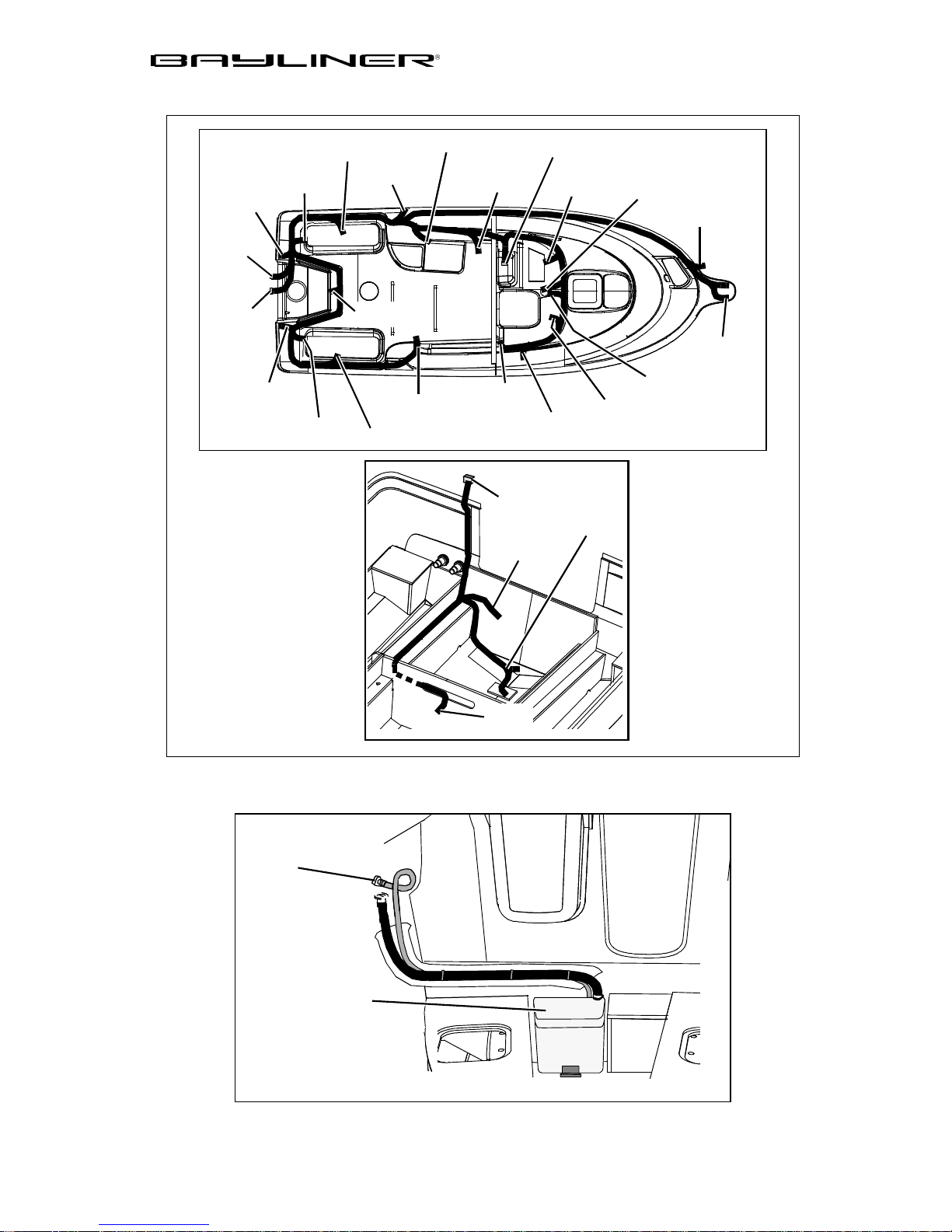
Deck & Bilge Harness
CHAPTER 4: DRAWINGS & DIAGRAMS 33
STERN
LIGHT
BILGE
PLUG
ENGINE
PLUG
ACCY
BREAKER
COURTESY
FISH WELL
PUMP
FISH WELL
PUMP
LIGHT
FUEL
GROUND
STERN
LIGHT
COURTESY
LIGHT
SPEAKER
SHIFTER
KILL
SWITCH
STEREO
BILGE
HARNESS
PLUG
BAIT WELL
PUMP
DASH
PLUG
WIPER
ANTENNA
WIRE
TO BILGE PUMP
& FLOAT SWITCH
TO
COMPASS
WIPERSPEAKER
HORN
INTERIOR
LIGHT
BOW
LIGHTS
Head Pump-out (Option)
PORTA-POTTY
VENT
PORTA-POTTY
TO FUEL
SENDER
Trophy Owner’s Manual Supplement
Page 40
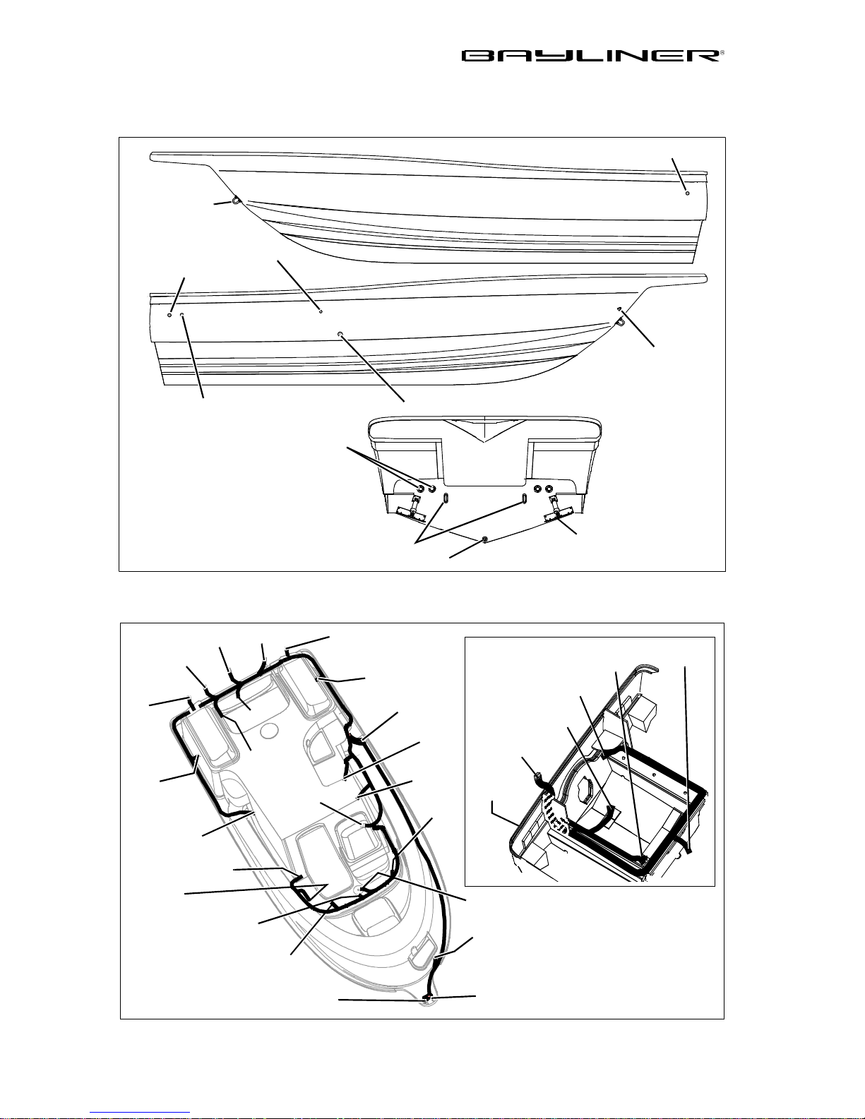
34 CHAPTER 4: DRAWINGS & DIAGRAMS
2052 (FD)
Hull Exterior Hardware
FISH WELL DRAIN
BOW EYE
FISH WELL
DRAIN
BILGE PUMP
OVERBOARD
FUEL
VENT
DECK DRAINS
(TYPICAL PORT/STBD)
STERN EYES
GARBOARD DRAIN
PORT HULLSIDE
STARBOARD HULLSIDE
ROPE
LOCKER
DRAIN
LIVE WELL DRAIN
TRANSOM
TRIM TAB
(TYPICAL PORT/STBD)
Electrical Harness Routings
INTERIOR
LIGHT
BILGE
PLUG
STERN
LIGHT
BUSS
BAR
PORT
WIPER
DASH
PLUG
PORT
BOW
LIGHT
PORT
FISHWELL
PUMP
PORT
COURTESY
LIGHT
TRIM
PUMP
PORT
SPEAKER
ANTENNA
WIRE
ENGINE
PLUG
STEREO
STBD.
FISHWE LL
PUMP
STBD.
COURTESY
LIGHT
FUEL
GROUND
SHIFTER
KILL
SWITCH
STBD.
SPEAKER
STBD.
WIPER
BILGE
HARNESS
PLUG
TRANSOM
COMPASS
LIGHT
HORN
STBD.
BOW
LIGHT
BLOWER
BILGE
PUMP &
FLOAT
SWITCH
BAIT
WELL
PUMP
TO FUEL
SENDER
Trophy Owner’s Manual Supplement
Page 41
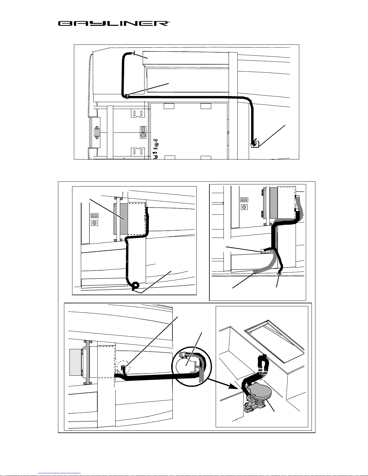
Raw Water (Option)
Marine Head (Option)
HOLDING
TANK
WASHDOWN
OUTLET
WASHDOWN
CHAPTER 4: DRAWINGS & DIAGRAMS 35
PUMP
STRAINER
SEA
SUMP
BOX
TANK VENT
THRU-HULL
SEACOCK
HEAD
MACERAT OR
PUMP
DECK WASTE
FITTING
TANK VENT
THRU-HULL
V-BERTH VIEW
HEAD
Trophy Owner’s Manual Supplement
Page 42
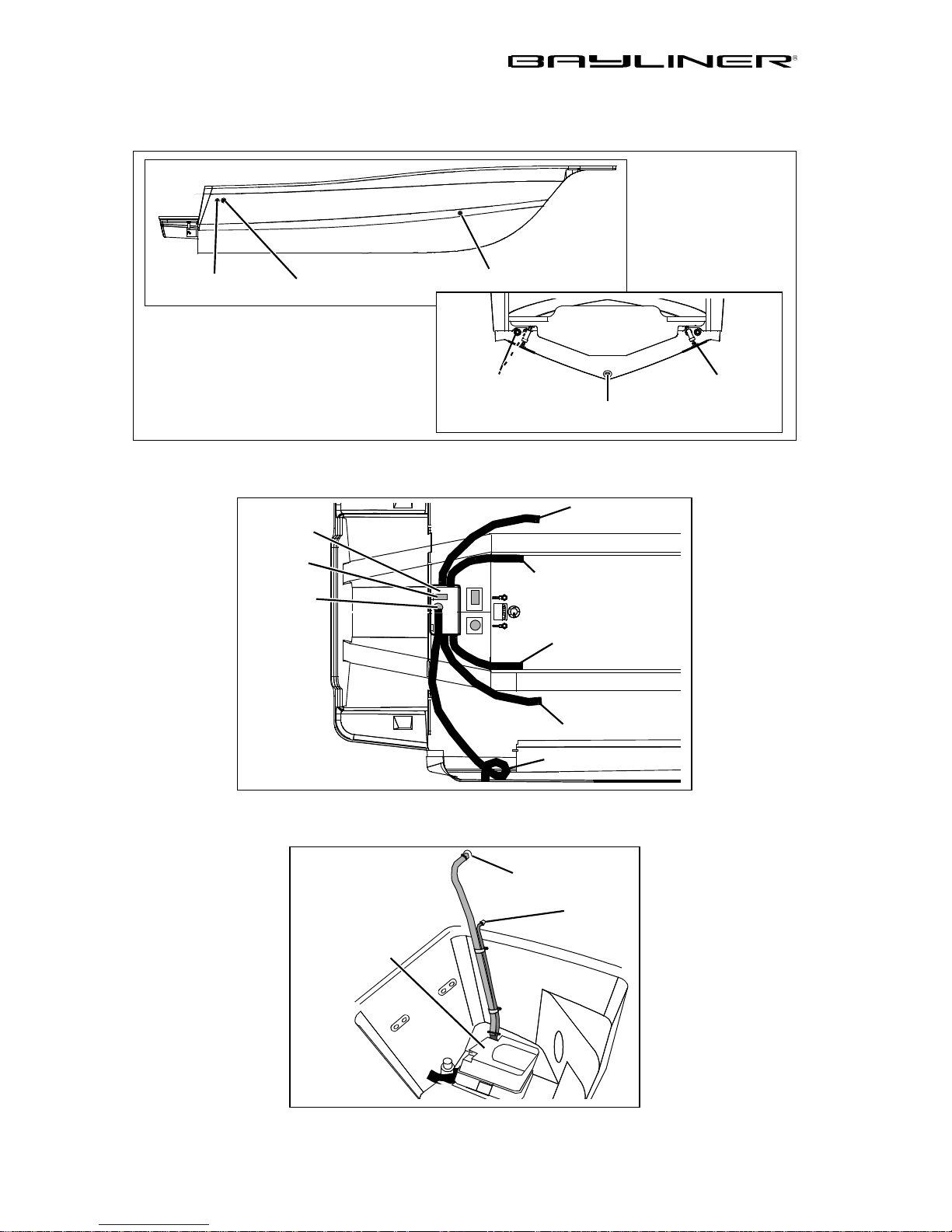
36 CHAPTER 4: DRAWINGS & DIAGRAMS
2503 (FM)
Hull Exterior Hardware
STARBOARD HULLSIDE
BILGE PUMP
DRAIN
SUMP BILGE
PUMP DRAIN
FISH WELL
DRAIN
TRANSOM
Fish Well/Bait Well Sump System
SUMP BOX
FLOAT
SWITCH
BILGE
PUMP
DECK DRAINS
(TYPICAL PORT/STBD)
FROM AERATOR TANK
TO THRU-HULL
GARBOARD
DRAIN
FROM FISHWELL
FROM FWD BILGE
FROM FISHWELL
TRIM TABS
(TYPICAL PORT/STBD)
Head Pump-out System (Option)
PORTA-POTTY
Trophy Owner’s Manual Supplement
TO WASTE
DECK FITTING
TANK VENT
THRU-HUL L
Page 43
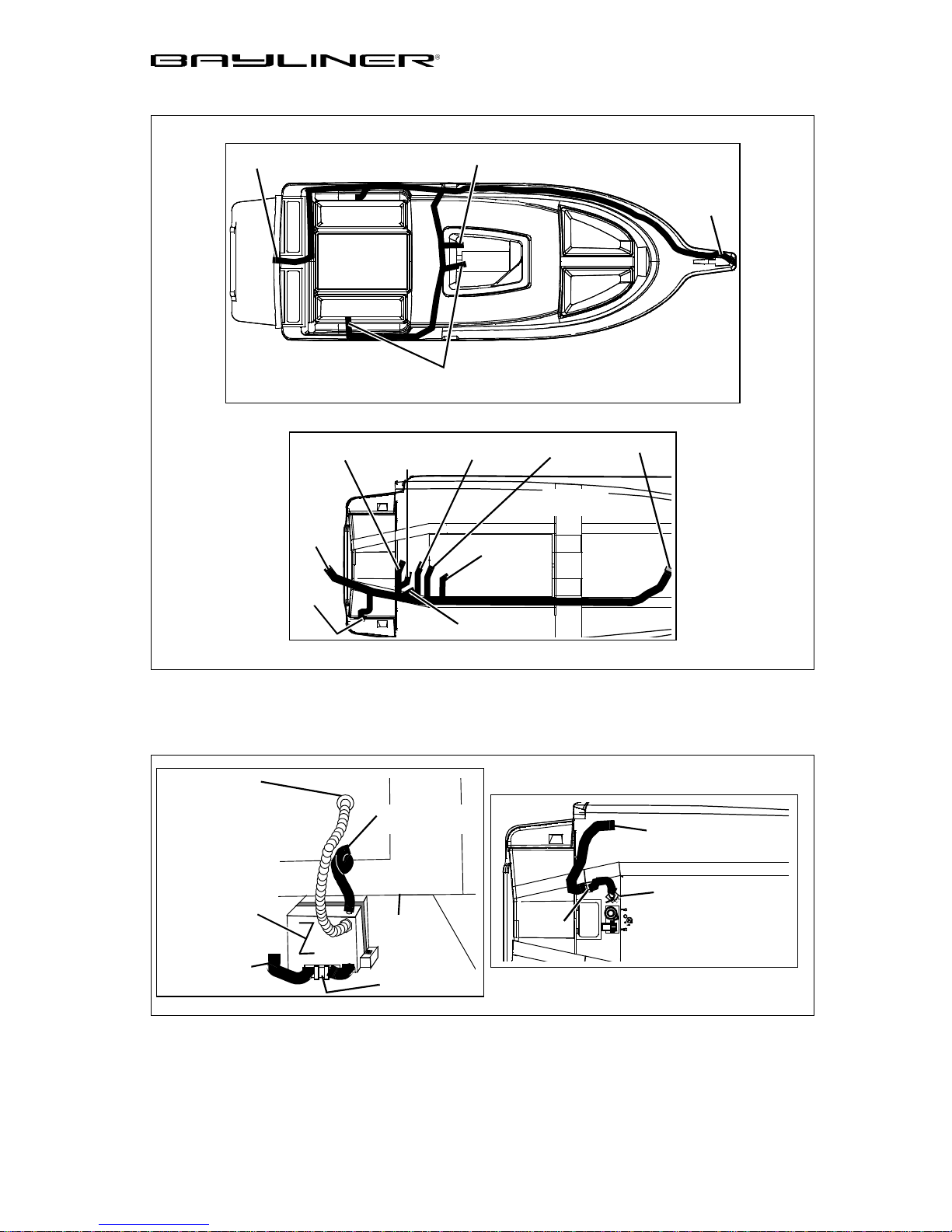
Wire Harness Routing
CHAPTER 4: DRAWINGS & DIAGRAMS 37
STERN
LIGHT
UNDERSIDE OF
DECK VIEW
TO
MOT OR
BA TTERY
SUMP
PUMP
COURTESY
LIGHTS
GARBOARD
DRAIN
GROUND
TO CONSOLE
TO BILGE
PUMP
FUEL TANK
SENDER
AERATOR
PUMP
SEACOCK
GROUND
HULL
TOP VIEW
CONSOLE
BOW
LIGHT
Water Systems (Options)
WATER FILL
DECK FITTING
FRESH WATER
SYSTEM (OPTION)
WATER TANK
TO WASHDOWN
ON DECK
WATER TANK
VENT THRU-HULL
FRESH WATER
PUMP
TO DECK
SEA STRAINER
PUMP
RAW WATER WASHDOWN
SYSTEM (OPTION)
Trophy Owner’s Manual Supplement
Page 44
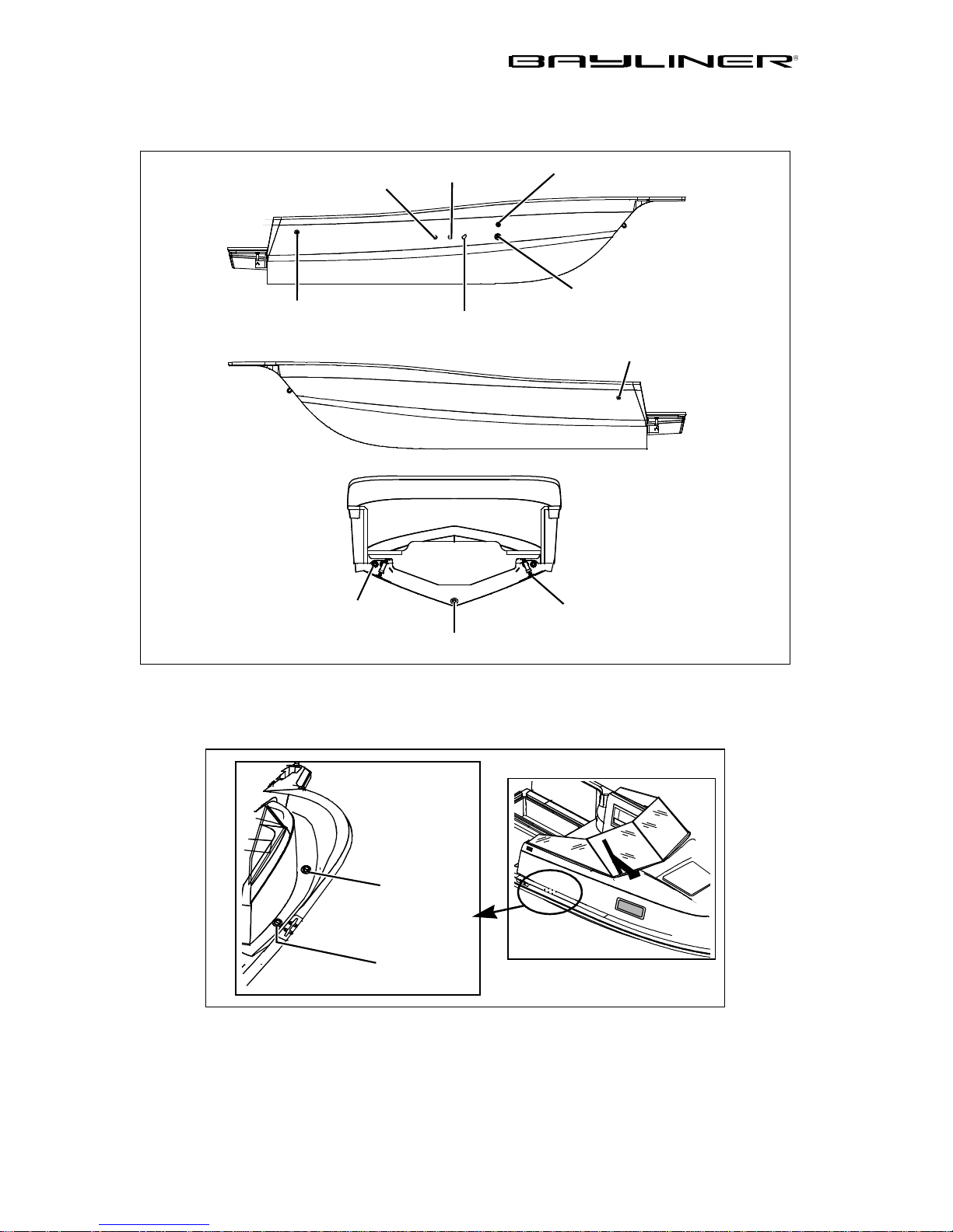
38 CHAPTER 4: DRAWINGS & DIAGRAMS
2509 (FW)
Hull Exterior Hardware
FWD BILGE
MACERATOR
DRAIN (OPTION)
STBD HULLSIDE
AFT BILGE
PUMP DRAIN
PORT HULLSIDE
PUMP DRAIN
HOLDING TANK
VENT (OPTION)
TRANSOM
WATER
TANK VENT
GALLEY SINK DRAIN
FISHWELL
SUMP DRAIN
Deck Hardware
DECK DRAINS
(TYPICAL PORT/STBD)
ENLARGED VIEW
WATER FILL
MARINE HEAD
PUMP OUT
DECK FITTING
(OPTION)
GARBOARD
DRAIN
TRIM TAB
(TYPICAL PORT/STBD)
Trophy Owner’s Manual Supplement
Page 45
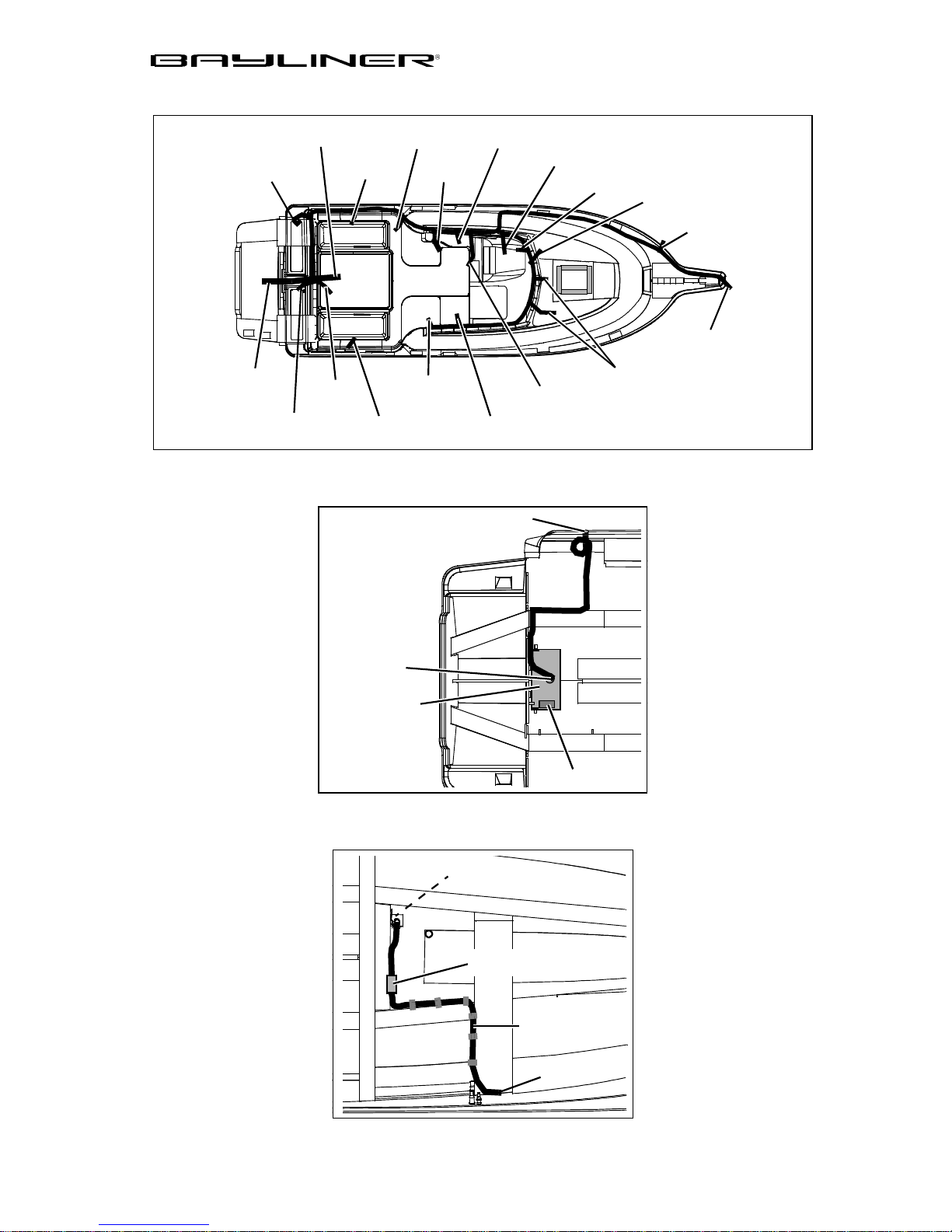
Deck Harness
BILGE
HARNESS
TRIM PUMP
ENGINE
STERN
LIGHT
FUEL
TANK
Fishwell Drain System
FWD HULL
HARNESS
COURTESY
LIGHT
COURTESY
LIGHT
SPEAKER
SPEAKER
CHAPTER 4: DRAWINGS & DIAGRAMS 39
SHIFTER
DASH PANEL
COMPASS
WIPER
HORN
BOW
LIGHT
CABIN
LIGHT
STEP LIGHT
CABIN LIGHT
THRU-HULL
BILGE PUMP
Bait Well Pick-up System
SUMP BOX
HIGH SPEED
PICK-UP
BAIT WELL
PUMP
FLOAT SWITCH
PUMP TO
AERATOR
TO BAIT WE LL
TANK
Trophy Owner’s Manual Supplement
Page 46
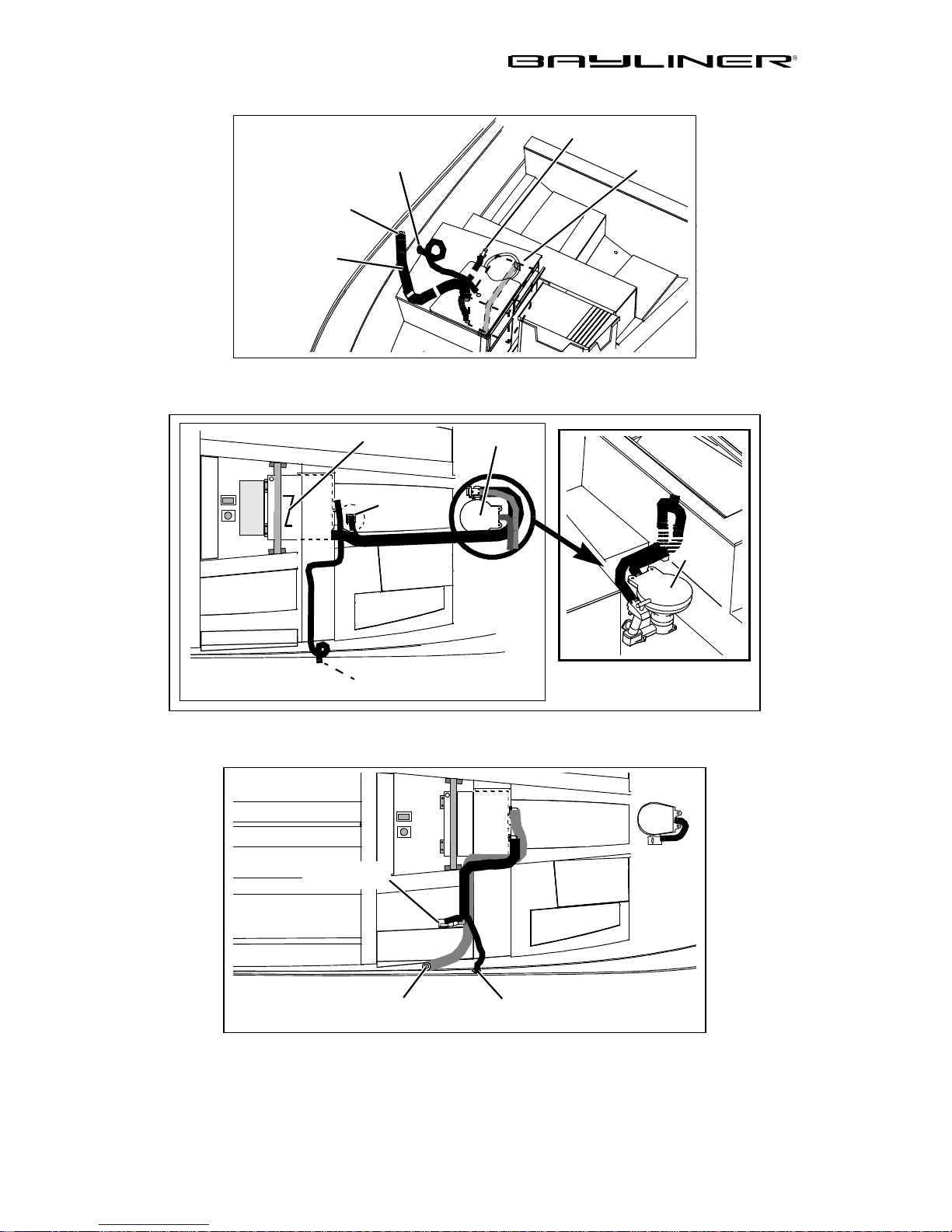
40 CHAPTER 4: DRAWINGS & DIAGRAMS
HEAD
Galley Water System
TANK VENT
THRU-HULL
WATER FILL
DECK FITTING
HOSE COVER
Marine Head (Option)
HAND PUMP
WATER
TANK
SUMP
BOX
Macerator (Option)
HOLDING
TANK
HOLDING TANK
VENT THRU-HULL
MACERATOR
PUMP
SEA
STRAINER
HEAD
DECK WASTE
Trophy Owner’s Manual Supplement
FITTING
TANK VENT
THRU-HULL
Page 47
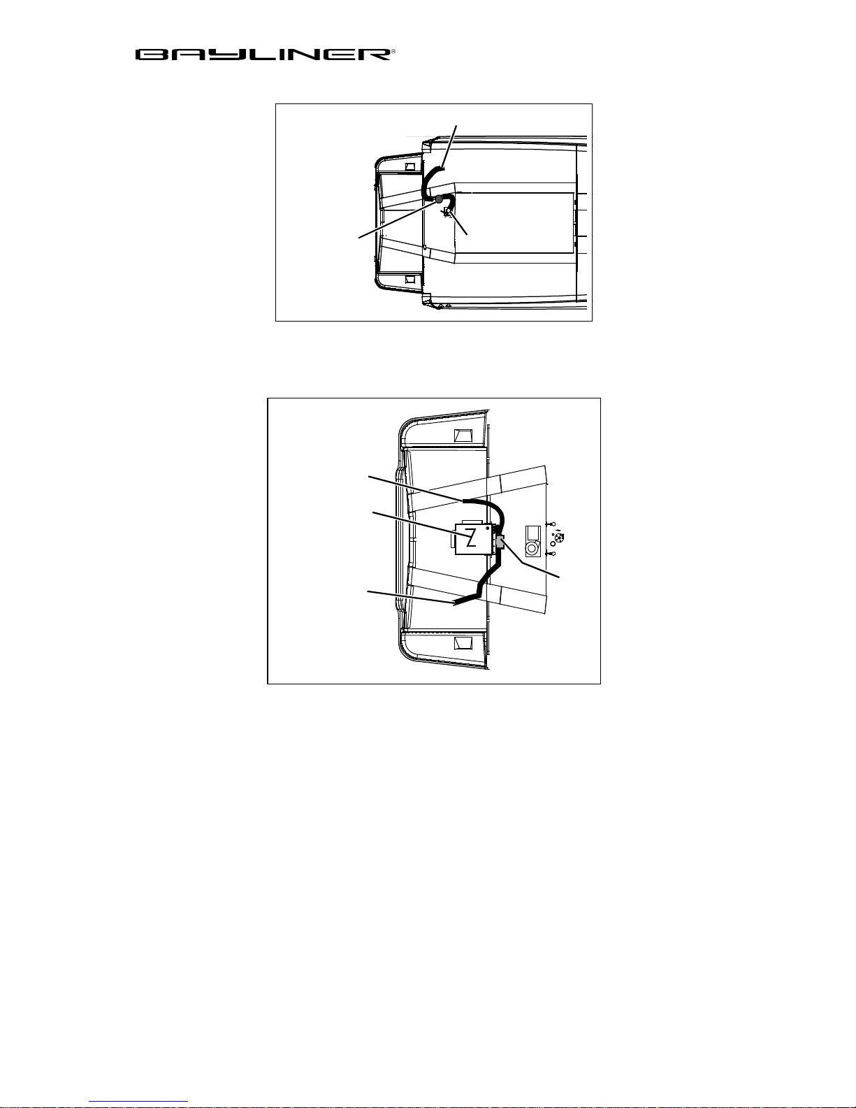
Raw Water (Option)
CHAPTER 4: DRAWINGS & DIAGRAMS 41
WASHDOWN
OUTLET
WASHDOWN
PUMP
Fresh Water Washdown System (Option)
TO WATER FILL
DECK FITTING
WATER
TANK
TO WASHDOWN
ON DECK
SEA STRAINER
PUMP
Trophy Owner’s Manual Supplement
Page 48
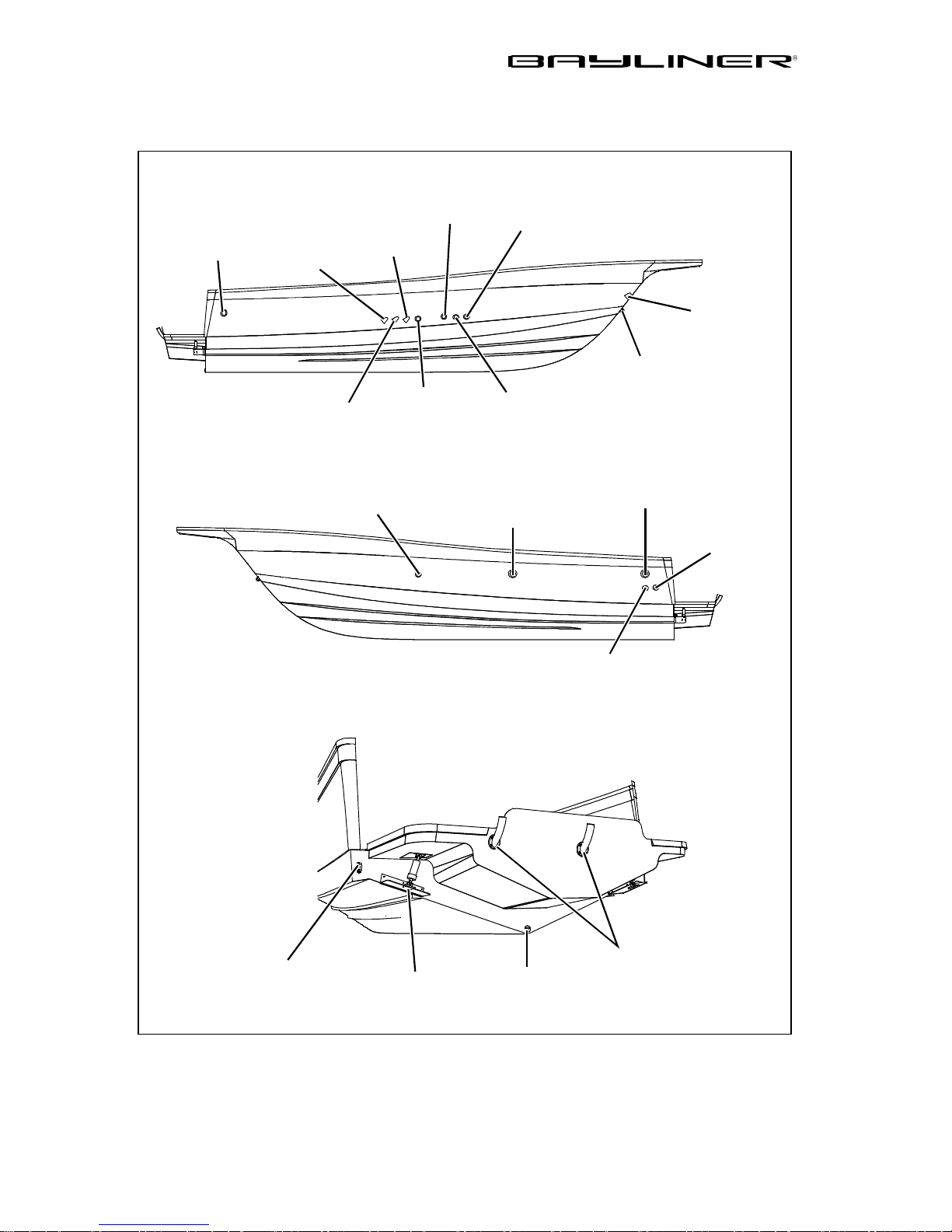
42 CHAPTER 4: DRAWINGS & DIAGRAMS
2802 (FH)
Hull Exterior Hardware
COCKPIT SINK
DRAIN
BAIT WELL
DRAIN
STBD HULLSIDE
WA TER
TAN K VENT
HOLDING
TANK VENT
GALLEY SINK
DRAIN
PORT HULLSIDE
FUEL
VENT
MACERATOR
PUMP OUT
(OPTION)
SHOWER
DRAIN
FWD
BILGE PUMP
COCKPIT
SINK DRAIN
ANCHOR
DRAIN COVER
BOW EYE
AFT SINK
DRAIN
AFT BILGE
PUMP
STERN EYE
(TYPICAL PORT/S TBD)
TRANSOM VIEW
TRIM
TABS
GARBOARD
FISHWELL
DRAIN
RIGGING TUBES
DRAIN
Trophy Owner’s Manual Supplement
Page 49
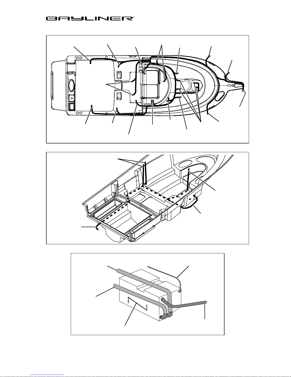
Deck Electrical Harness
CHAPTER 4: DRAWINGS & DIAGRAMS 43
LIGHT
LIGHT
COURTESY
LIGHT
LIGHT
COURTESY
Shore Power Routing
AC PANEL
LIGHT
FROM
SPEAKER
SPEAKER
LIGHT
RADIO PLUG
SWITCHES
WIPER
LIGHT
WIPER
SPEAKER
LIGHTS
HORN
BOW
LIGHT
SPEAKER
TO BATTERY
CHARGER
Waste Holding Tank
DECK FITTING
TANK TO
MACERATOR
TO HEAD
OUTLET
TO HOT WATER
HEATER
TANK TO
TO VENT
THRU-HULL
FROM HEAD
WASTE TANK
Trophy Owner’s Manual Supplement
Page 50
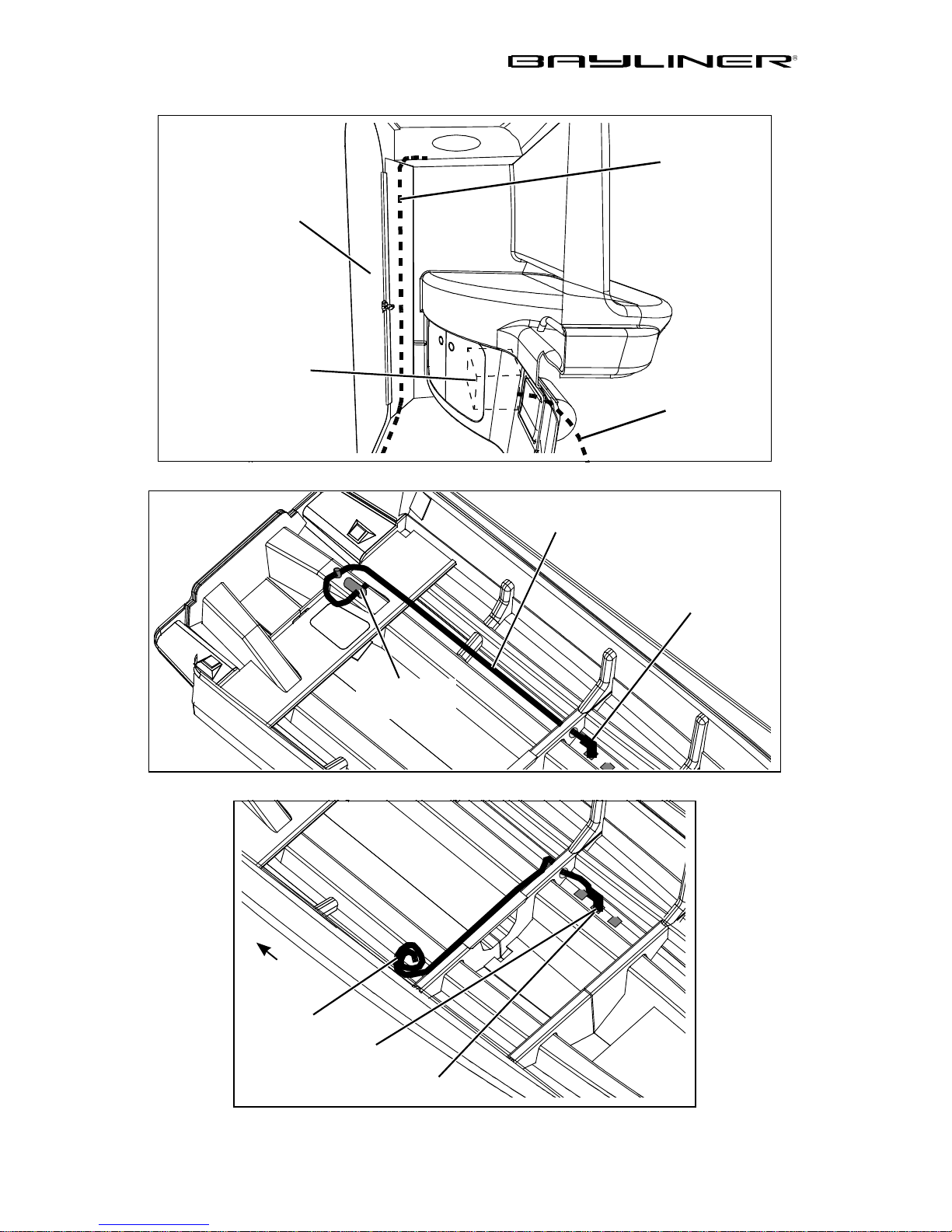
44 CHAPTER 4: DRAWINGS & DIAGRAMS
Head Wire Routing
FWD VIEW
DOOR
TO HEAD
WATER HEATE R
LOCATION (OPTION)
Deck Washdown System
ROUTE TO
OUTLET
TO WATER
HEATER
(OPTION)
SEACOCK TO
PUMP
Head Pick-up System
AFT
PICKUP
TO HEAD
WASHDOWN
THRU-HULL
WASHDOWN
PUMP
TO
THRU-HULL
Trophy Owner’s Manual Supplement
HEAD
Page 51
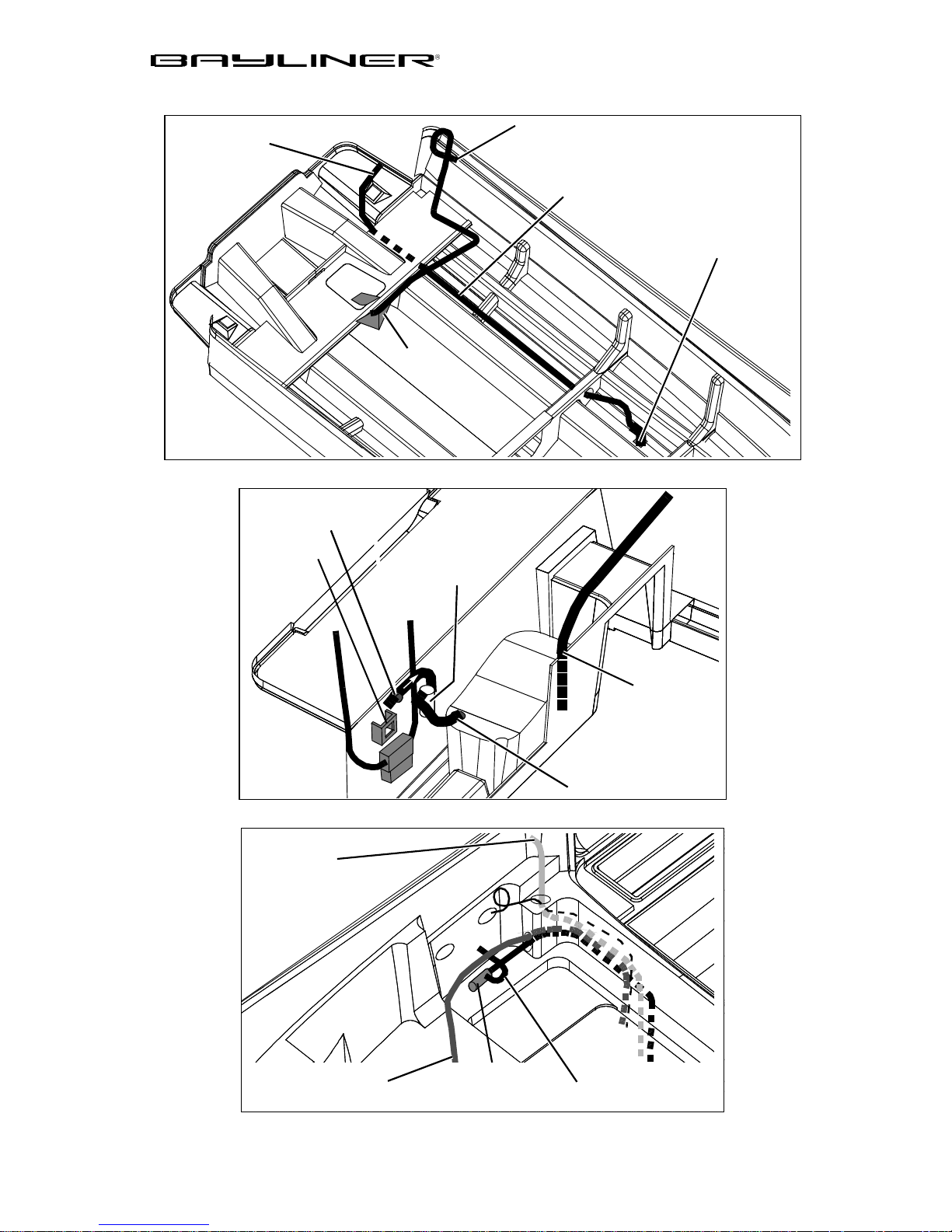
Bait Well System
TO BAIT WELL
FILTER ON
TRANSOM
DECK
Deck Transom Hook-ups
CHAPTER 4: DRAWINGS & DIAGRAMS 45
THRU-HULL
FROM SEACOCK
TO PUMP
BAIT WELL
PICKUP
SUMP
FILTER
BATTERY
SWITCH
Macerator Pump Location
TO DECK
WASTE FITTIN G
BAIT WELL
PUMP
LOWER
BAIT WELL
DRAIN
TO AERATOR
TO HEAD
MACERATOR
PUMP
MACERATOR
DISCHARGE
Trophy Owner’s Manual Supplement
Page 52
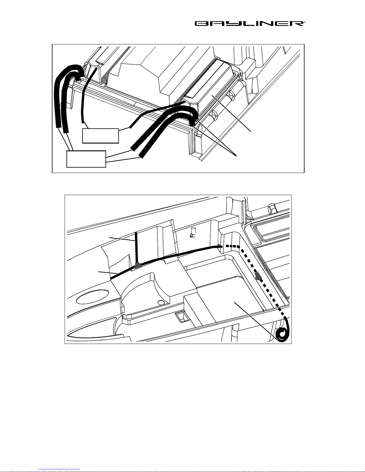
46 CHAPTER 4: DRAWINGS & DIAGRAMS
Aft Liner Drain System
FISH WELL
TO SUMP
TO
THRU-HULL
Hot Water System (Option)
HOT TO
HEAD SINK
FROM
WA TER
HEATER
(TYPICAL PORT/STBD)
FISH WELL
LINER DRAIN
THRU-HULL
HOT TO
GALLEY SINK
Trophy Owner’s Manual Supplement
Page 53
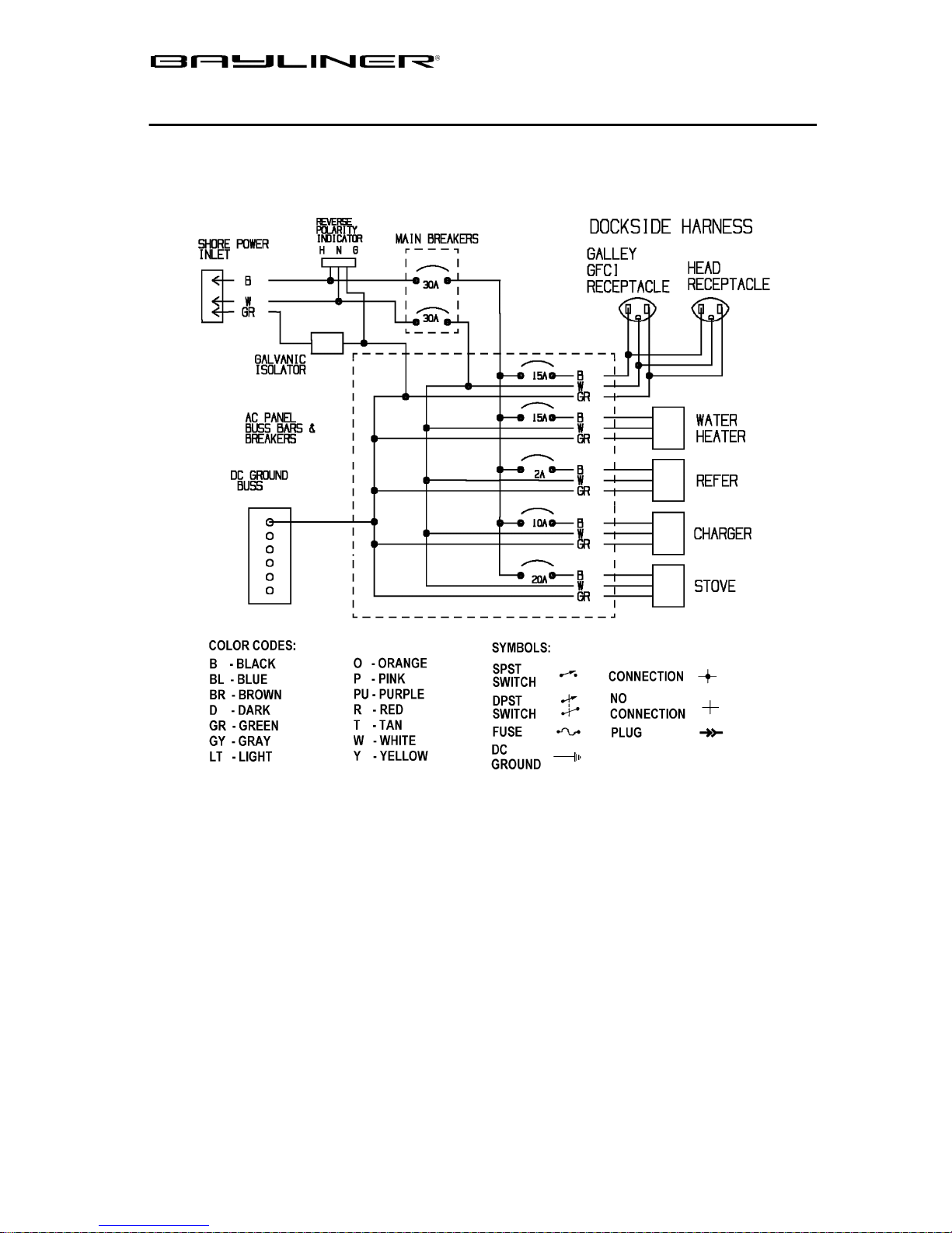
CHAPTER 4: WIRING DIAGRAMS
Shore Power
47
Trophy Owner’s Manual Supplement
Page 54
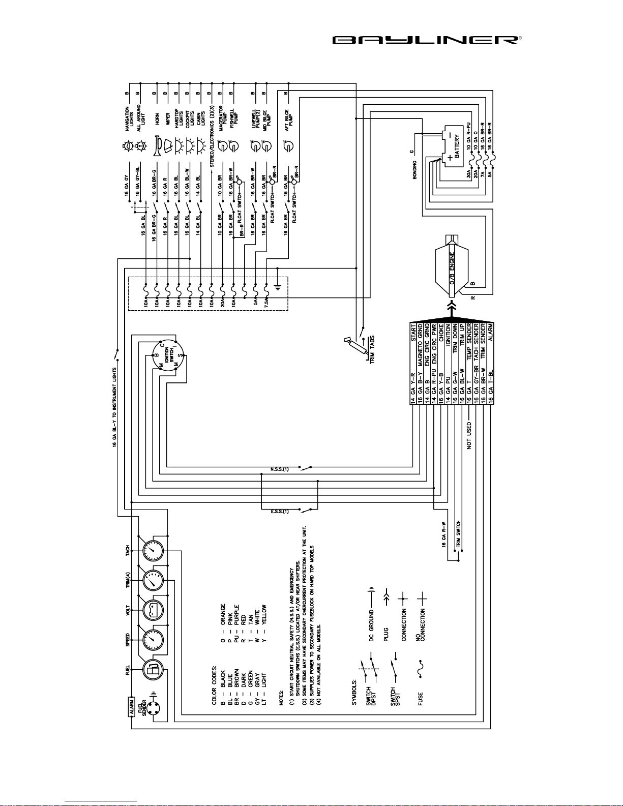
48 CHAPTER 4: WIRING DIAGRAMS
Single En gi ne (O ut bo ar d), Typical
Trophy Owner’s Manual Supplement
Page 55
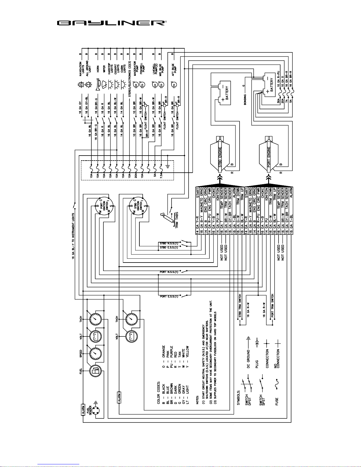
Twin Engine (Outboard), Typical
CHAPTER 4: WIRING DIAGRAMS 49
Trophy Owner’s Manual Supplement
Page 56
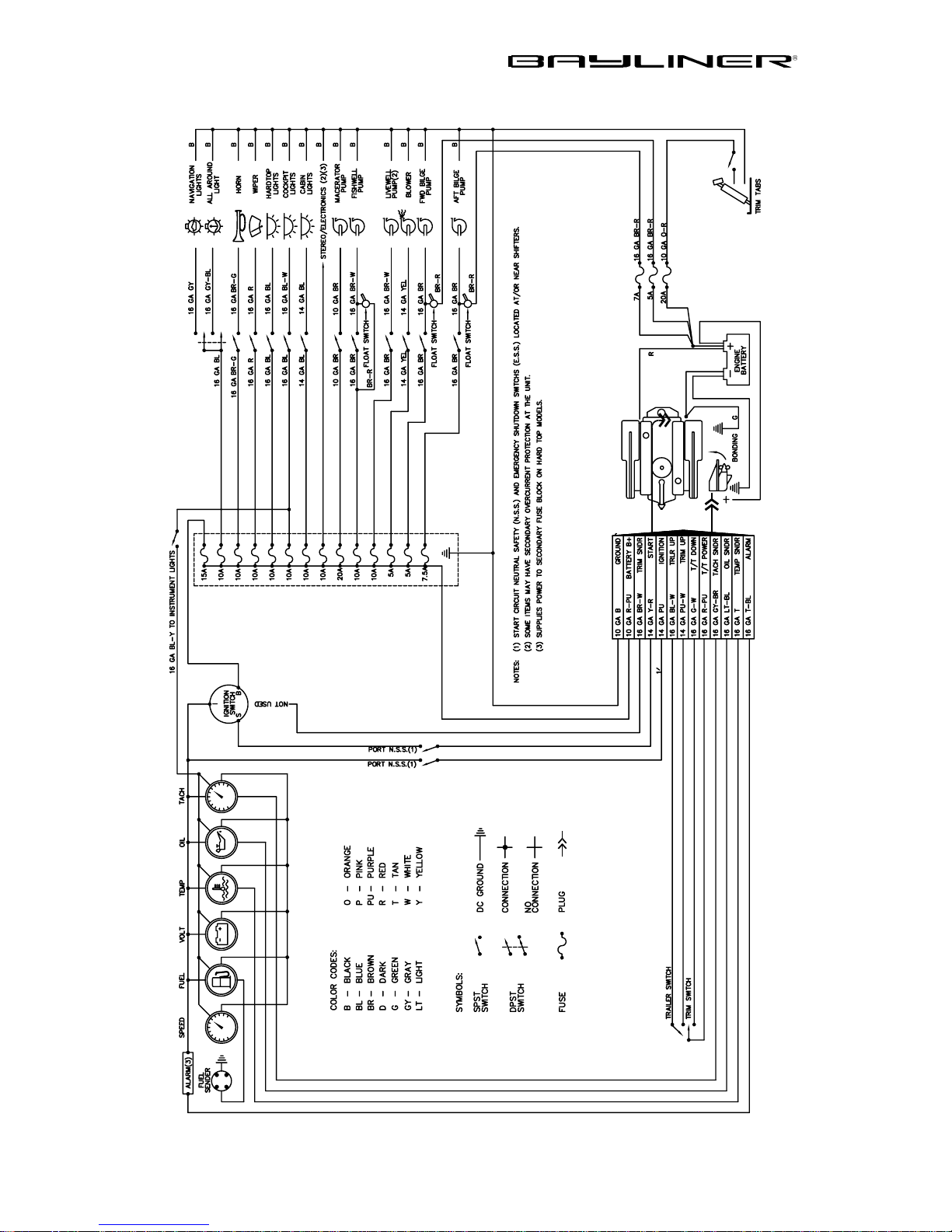
50 CHAPTER 4: WIRING DIAGRAMS
Stern Drive, Typical
Trophy Owner’s Manual Supplement
Page 57

51
LIMITED WARRANTY
Bayliner warrants to the orig inal purchasers of its 2001 and 2002 model Trophy, purchased from an
authorized dealer , operated under normal, noncommercial us e that the sellin g dealer will: (A) Repair any
structural hull defect which occurs within ten (10) years of the date of delivery; and (B) Repair or replace
any parts found to be defective in fact ory ma te rial or work manship within one (1) year of the date of
delivery.
What Is Not Covered
This limited warranty does not apply to:
1. Engines, drive train s, co ntr ols, props, batteries, or other equipm ent or accessories carrying their
own individual warranties;
2. Engines, parts or accessorie s not installed by Bayliner;
3. Acrylic windscreen breakage; rainwater leakage on runabout models; rainwater leakage through
convertible tops; minor gelcoat discoloration, cracks or crazing or air voids;
4. Hull blisters that form below the waterline;
5. Normal deterioration, i.e. wear, tear, or corrosion of hardware, vinyl, tops, vinyl and fabric upholstery, plastic, meta l, wood, or trim tape;
6. Any Bayliner boat which has been overpowered according to the maximum horsepower specifications on the capacity pl ate provided on each Bayl iner out board boat;
7. Any Bayliner boat used for commercial purposes;
8. Any defect caused by failure of the customer to pr ovi de reasonable care and ma intenance.
Other Limitations
THERE AR E NO OTHER EXPRESS WARRANTI ES ON THIS BOAT. TO THE EXTE N T
ALLOWED BY LAW:
1. ANY IMPLIED WARRANTY OF MERCHANT ABILITY OR FITNESS FOR A PARTICULAR
PURPOSE IS LIMITED TO THE DURATION OF ONE YEAR.
2. Neither Bayliner nor the selling deale r shall have any responsibility for loss of use of the boat,
loss of time, inconvenien ce, commercial loss or consequent ial da m ages.
3. Some jurisd ict io n s do n ot allow limitatio ns on ho w lo n g a ny implied warranty last s, so th e above
limitation may not ap pl y to you. Some jurisdictions do not allow th e exclusion or limitation of
incidental or cons equential damages, so the above limitation or excl usion may not apply to you.
This limited warranty gi ve s you specific legal rights, and you may also ha ve other rights which
vary from state to state.
Your Obligation
In order to comply with regulations, it is essential that your limited warranty registration card be submitted
within 30 days of delivery of your boat. Return of the limited warranty registration card is a condition precedent to limited warranty coverage. Before any warranty work is performed, w e requi re that you contact
your dealer to request warranty assistance.
YOU MUST GIVE US WRITTEN NOTICE OF YOUR WARRANTY CLAIM PRIOR TO THE EXPIRATION OF YOUR LIMITED WARRANTY AND ALLOW US AN OPPORTUNITY TO RESOLVE
THE MATTER.
We require that you return your boat, at your expense, to your s elling dealer or, if necessary, to the Bayliner factory. You will be responsible for all transportation, haulouts and other expenses incurred in returning the boat for warranty service.
Bayliner Marine Corporation
PO Box 9029
Everett, WA 98206
Phone: 360-435-8957
F AX: 360-403-4235
Trophy Owner’s Manual Supplement
Page 58

Owner’s Notes
Part Number 117903
Page 59

Page 60

Ba y line r M a rin e • P.O. Box 9029 • Everett, WA 98206 • 360-435-5571
Part Number 117903
 Loading...