

Page 1
Page 2

Page 3
Engine Serial Number: _____________________________________________
Hull Identification Number:__________________________________________
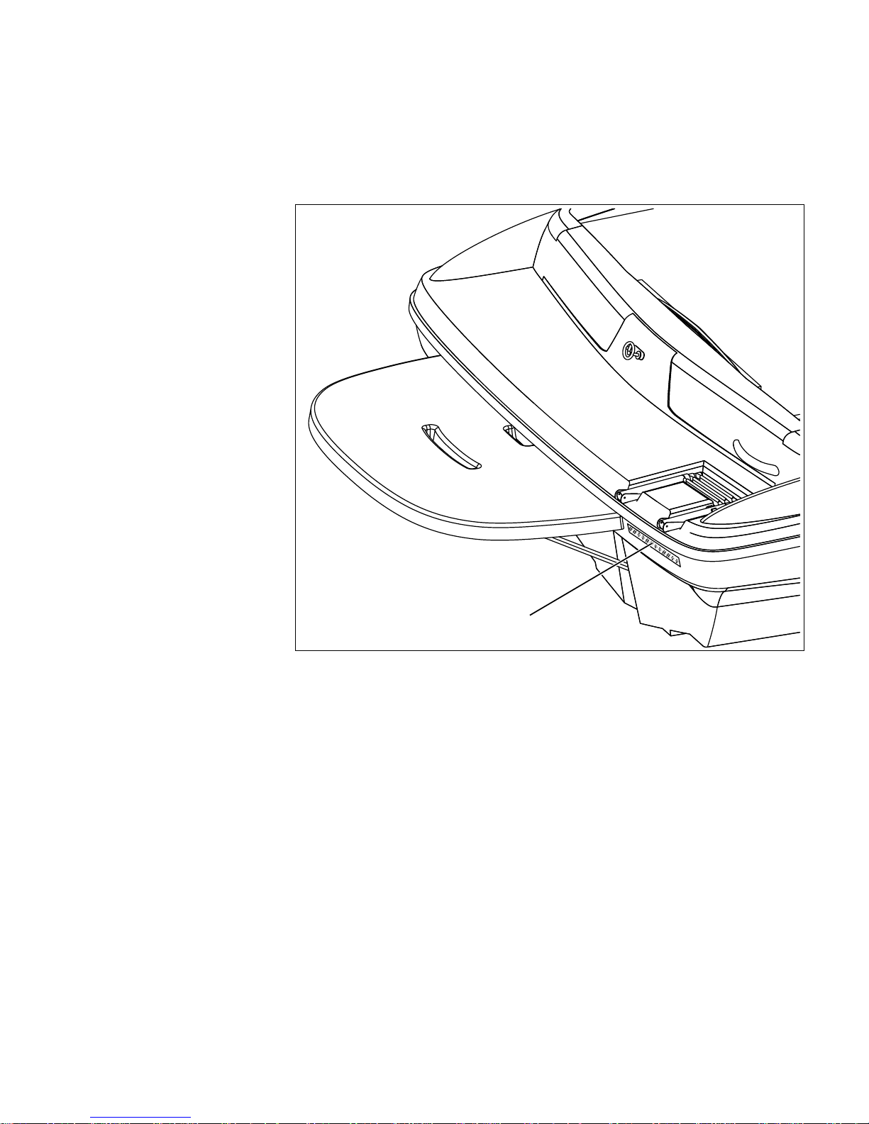
Hull Identi fication Number
• The Hull Identification Number (HIN) is located on th e
starboard side of the transom.
• Record the HIN (and the
engine serial numbers) in the
space provided above.
• Please refer to the HIN for any
correspondence or orders.
HIN LOCATION
© 2003 Bayliner Technical Publications. All rights reserved.
No part of this publication may be reproduced, stored in any retrieval system, or transmitted in any form by any means, electronic, mechanical, photocopying,
recording or otherwise, without prior written permission of Bayliner.
Printed in the United States of America.
General Notes
The material in this document is for information only and is subject to change without notice. While reasonable efforts have been made in the preparation of this
document to assure its accuracy, Bayliner assumes no liability resulting from errors or omissions in this document, or from the use of information contained herein.
Due to our commitment to product improvement, Bayliner reserve s t he right to make changes in the product design, specifications, and equipment at any time
without notice or obligation. Illustrations and/or photos may show optional equipment.
All Bayliner products meet or exceed USCG (Unites States Coast Guard) and/or NMMA (National Marine Manufacturer’s Association) construction standards.
Manufactured with 1,1,1 Trichloroethane, a substance which harms public health and environment during the manufacturing process by destroying ozone in the
upper atmosphere.
Proprietary Rights
This document discloses subject matter in which Bayliner has proprietary rights. The information and des ign disclosed herein were originated by and are the property of Bayliner. Neither receipt nor possession thereof confers or transfers any right to reproduce, copy, alter or disclose the document or any part thereof, any
information contained therein, or to const ruct boats or any i tem from it, e xcept by writt en permis sion from or writt en agr eemen t with Bayliner. This document is to
be returned upon request to Bayliner.
Page 4

CONTENTS
1 Chapter 1: Welcome Aboard!
1 Dealer Service
1 Warranty Information
1 Boating Experience
2 Safety Standards
2 Engine & Accessories Guidelines
3 Engine & Accessories Literature
3 Qualified Maintenance
3 Special Care For Moored Boats
4 Carbon Monoxide (CO)
4 Facts about CO
5 Where and How CO Can Accumulate
5 How to Protect Yourself and Others From CO
6 Trip Checklist
6 Monthly Checklist
6 Annual Checklist
6 More Information
7 Chapter 2: Product Specifications
16 Chapter 4: Propulsion &
Related Systems
16 Engine
16 Engine Room Ventilation System
17 Fuel System
17 Fuel Fill and Vent
17 Fuel Filters
18 Chapter 5: Controls & Gauges
18 Steering
18 Shift/Throttle Lever
18 Power Trim and Tilt
18 Gauges
18 Cleaning Gauges
18 Gauge Fogging
18 Radio Transmission Interference
18 Fuel Gauge
19 Chapter 6: Plumbing
7 185
8 205
9 225
10 Chapter 3: Locations
10 Exterior Views
10 Hull Views
11 Extended Swim Platform (If Equipped)
12 185 Deck View
13 205 Deck View
14 225 Deck View
15 Component Locations
19 Bilge Pump
21 Auto-float Switch (225 Only)
22 Freshwater Transom Shower (If Equipped -
225 Only)
24 Chapter 7: Deck Equipment
24 Cleats and Tow Eyes
24 Ski Tow Ring
25 Ski-Tow Tower (If Equipped)
25 Attaching the Ski-Tow Rope
26 Folding Ski-T ow To wer (205 & 225 Only)
27 Canvas (If Equipped)
27 Convertible Top
28 Side Curtains (If Equipped)
29 185 Bimini Top (If Equipped)
30 205/225 Bimini Top (If Equipped)
31 Bow Cover (If Equipped)
Page 5

32 Chapter 8: Enter tainment Systems
38 Chapter 11: Electrical System
32 Audio System
33 Chapter 9: Convertibl e Seats,
Beds, & Tables
33 Sleeper Seats (If Equipped - 185/205 Only)
33 Operating Positions
33 Lounge positions
34 Jump Seat To Sunlounge Conversion (If
Equipped - 185/205 Only)
35 Passenger Seat to Lounge Conversion
(225 Only)
37 Chapter 10: Lights
37 Care and Maintenance
37 Navigation Lights
39 12-Volt DC System
39 Battery
39 Fuses and Circuit Breakers
39 Alternator
39 12-Volt Accessory Outlet(s)
40 Electrical Routings
40 185 & 205 Deck Electrical Harness
41 225 Deck Electrical Harness
42 Hull Electrical Harness
43 Wiring Diagrams
43 185 & 205
44 225
45 Important Records
46 Float Plan
Page 6
Hazard Boxes & Symbols
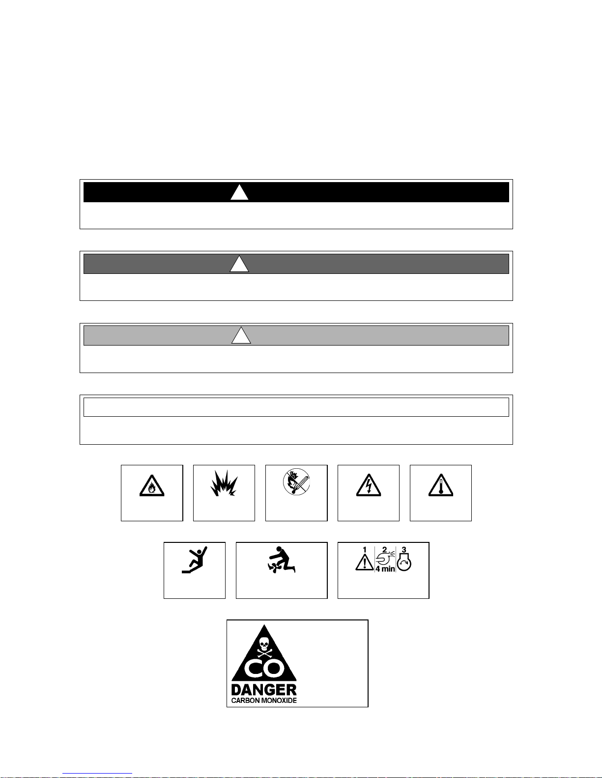
The hazard boxes and symbols shown below are used throughout this supplement to call attention to potentially dangerous situations which could lead to either personal injury or product damage. Read ALL warnings carefully and
follow all safety instructions.
!
DANGER!
This box alerts you to immedia te hazards which WI LL cause sev er e personal i njury or death if
the warning is ignored.
WARNING!
!
This box alerts you to haz ards or unsafe practices which COULD resul t in severe personal
injury or death if the warning is ignored.
!
CAUTION!
This box alerts you to haz ards or unsafe practices which COULD resul t in mi nor pe rsonal
injury or cause product or property damage if the war ning is i gnored.
NOTICE
This box calls attention to installation, operation or maintenance information, which is important to proper operation but is not hazard r ela ted.
FIRE
HAZARD!
EXPLOSION
FALLING
HAZARD!
HAZARD!
NO OPEN
FLAME!
ROTATING
PROPELLER HAZARD!
CO POISO N ING
HAZARD!
ELECTRICAL
HAZARD!
RUN BILGE BLOWERS
FOR 4 MINUTES!
HOT
HAZARD!
Page 7

185, 205 & 225 • Owner’s Manual Supplement
Chapter 1: Welcome Aboard!
This Owner’s Manual Suppleme nt provi des s pecif ic i nformat io n about your boat that is not c overed i n the Sport Bo at
Owner’s Manual. Please study the Sport Boat Owner’s Manual and this supplement carefully. Keep the Sport Boat
Owner’s Manual and this supplement on your boat in a secure, yet readily available place.
Dealer Service
• Your dealer is your key to service.
• Ask your dealer to explain all systems before taking delivery of your boat.
• Contact your dealer if you have any problems with your new boat.
• If your dealer cannot help, call our customer service hotline: 360-435-8957 or send us a FAX: 360-403-4235.
• Buy replacement parts from any authorized Bayliner dealer.
Warranty Information
• Bayliner offers a Limited Warranty on each new Bayliner purchased through an authorized Bayliner dealer.
• A copy of the Limited Warranty was included in your owner’s packet.
• If you did not receive a copy of the Limited Warranty, please contact your dealer or call 360-435-8957 for a copy.
Boating Experience
WARNIN G!
!
CONTROL HAZARD!
A qualified operator must be in control of the boat at all times. DO NOT operate your boat
while under the influence of alcohol or dr ugs.
If this is your first boat or if you are changing to a type of boat you are not familiar with, for your own comfort and
safety, obtain handling and operating experience before assuming command of the boat.
Take one of the boating safety classes offered by the U.S. Power Squadrons or the U.S. Coast Guard Auxiliary. For
more course information, including dates and locations of upcoming classes, contact the organizations directly:
• U.S. Power Squadrons: 1-888-FOR-USPS (1-888-367-8777) or on the Internet at: http://www.usps.org
• U.S. Coast Guard Auxiliary: 1-800-368-5647 or on the Internet at: http://www.cgaux.org
Outside the United States, your selling dealer, national sailing federation or local boat club can advise you of local
sea school s or competent instructors.
1
Page 8
Chapter 1: Welcome Aboard! 185, 205 & 225 • Owner’s Manual Supplement
Safety Standards
DANGER!
!
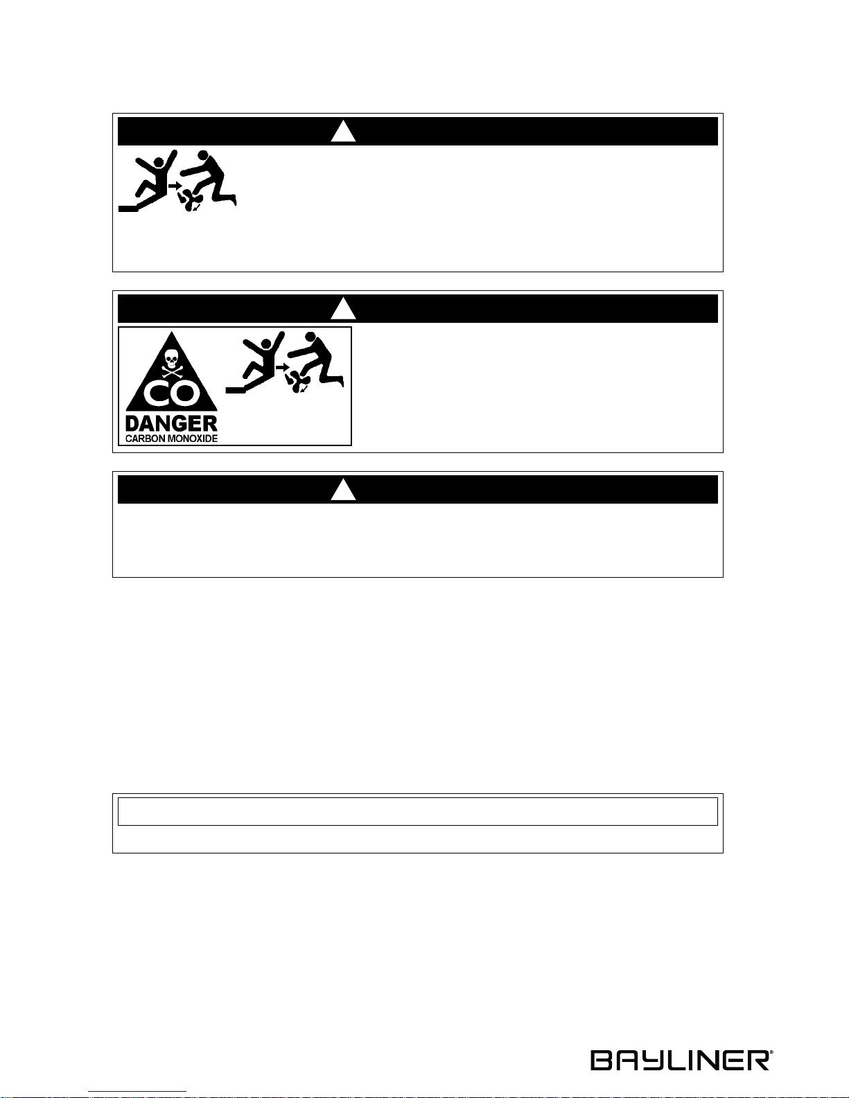
F ALLING and RO T A TING PROPELLER HAZARD!
NEVER allow anyone to ride on part s of t he boa t not designed for
such use.
• Sitting on seat backs, lounging on the forward deck, bow riding, gunwale riding or occupying the transom platform while underway i s especially hazardous and will cause personal
injury or death.
DANGER!
!
RO T A TING PR OPELLER and CARBON MONOXIDE
POISONING HAZARD!
• NEVER allow anyone to occupy, or hang from, the
back deck or swim platf orm whil e t he engi ne(s )
are running.
• Teak surfing, dragging, or water skiing withi n 20 feet
of a moving waterc raft can be fat al.
DANGER!
!
PERSONAL SAFETY HAZARD!
ALWAYS secure the anchor and other loose objects before ge tt ing unde rway. The anchor and
other items that are not properly secured can come loose when the boat is moving and cause
personal injury or death.
• Your boat’s mechanical and electrical systems were designed to meet safety standards in effect at the time it
was built.
• Some of these standards were mandated by law, all of them were designed to insure your safet y, and the safety of
other people, vessels and property.
In addition to this Owner’s Manual Supplement, please read the Sport Boat Owner’s Manual and all accessory
instructio ns for important safety standards and hazard informat ion.
Engine & Accessories Guidelines
NOTICE
When storing your boat ple ase refer to your engine’s operation and mai ntenance manuals.
• Your boat’s engine and accessories were selected to provide optimum performance and service.
• Installing a different engine or other accessories may cause unwanted handling characteristics.
• Should you choose to install a different engine or to add accessories that will affect the boat’s running trim, have
an experienced marine technician perform a safety inspection and handling test before operating your boat again.
Certain modifications to your boat can result in cancellation of your warranty protection. Always check with
your dealer before making any modifications to your boat.
2
Page 9
185, 205 & 225 • Owner’s Manual Supplement Chapter 1: Welcome Aboard!
Engine & Accessories Literature
• The engine and accessories installed on your boat come with their own operation and maintenance manuals.
• Read and understand these manuals before using the engine and accessories.
• Unless noted otherwise, all engine and accessory literature referred to in this supplement is included in your
owner’s packet.
Qualified Maintenance
WARNIN G!
!
To maintain the integrity and safety of your boat, al low only qualified personnel to perform
maintenance on, or in any way modify: The steering system, propul sion system, engi ne contr ol
system, fuel system, environmental control system, electrical sys tem or navigational system.
• Failure to maintain your boat’s systems (listed in the warning above) as designed could violate the laws in your
jurisdiction and could expose you and other people to the danger of bodily injury or accidental death.
• Follow the instructi ons pr ovide d in t he Sport Boat Owne r’s Manual, this Owner’s Manual Supple ment , the engine
owner’s manual and all accessory instruction sheets and manuals.
Special Care For Moored Boats
NOTICE
• T o help s eal the hul l bottom and reduc e the possi bility of gelcoat bl istering on moored bo ats,
apply an epoxy barrier coating . The barri er coating should be covered with sev eral coat s of
anti-fouling pain t.
• Many states regulate the chemical content of bottom paints in order to meet environmental
standards. Check with your l ocal deal er about recommended bottom paints, and about the
laws in effect in your area.
• Whether moored in saltwater or freshwater, your boat will collect marine growth on its hull bottom.
• This will detract from the boat’s beauty, greatly affect its performance and may damage the gelcoat.
• Periodically haul the boat out of the water and scrub the hull bottom with a bristle brush and a solution of soap
and water.
3
Page 10
Chapter 1: Welcome Aboard! 185, 205 & 225 • Owner’s Manual Supplement
Carbon Monoxide (CO)
DANGER!
!
• Carbon monoxide gas (CO) is colorless, odorless, tasteless, and
extremely dangerous.
• All engines, generato rs, and f uel b u rning appliances produce CO
as exhaust.
• Prolonged exposure to lo w conce ntrat ions or very quick exposur e to high
concentrations will cause BRAIN DAMAGE or DEATH.
• Teak surfing, dragging, or water skiing within 20 feet of a moving watercraft can be fatal.
Facts about CO
• CO poisoning causes a significant number of boating deaths each year.
• Called the "silent killer", CO is an extremely toxic, colorless, odorless and tasteless gas.
• CO can harm or even kill you inside or outside your boat.
• CO can affect you whether you’re underway, moored, or anchored.
• CO symptoms are similar to seasickness or alcohol intoxication.
• CO can make you sick in seconds. In high enough concentrations, even a few breaths can be fatal.
• Breathing CO blocks the ability of your blood to carry oxygen.
• The effects are cumulative, even low levels of exposure can result in injury or death.
Factors That Increase the Effects of CO Poisoning
• Age
• Smokers or people exposed to high concentrations of cigarette smoke
• Consumption of alcohol
• Lung disorders
• Heart problems
• Pregnancy
4
Page 11
185, 205 & 225 • Owner’s Manual Supplement Chapter 1: Welcome Aboard!
Where and How CO Can Accumulate
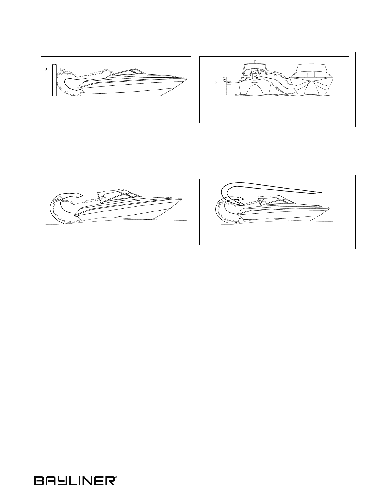
Stationary Conditions That Increase CO Accumulations Include:
A. Using engine, generator, or other fuel burn-
ing device when boat is moored in a confined space.
B. Mooring too close to another boat that is
using its engine, generator, or other fuel
burning device.
To correct stationary situations A and/or B:
• Close all windows, portlights and hatches.
• If possible, move your boat away from source of CO.
Running Conditions That Increase CO Accumulations Include:
C. Running boat with trim angle of bow too high. D. Running boat without through ventilation (sta-
tion wagon effect).
To correct running situations C and/or D:
• Trim bow down.
• Open windows and canvas.
• When possible, run boat so that prevailing winds help dissipate exhaust.
How to Protect Yourself and Ot hers From CO
• Know where and how CO may accumulate in and around your boat (see above).
• Maintain fresh air circulation throughout the boat at all times.
• Know where your engine and generator exhaust outlets are located and keep everyone away from these areas.
• Never sit on, or hang onto, the back deck or swim platform while the engine(s) are running.
• Never enter the areas under swim platforms where exhaust outlets are located.
• Although CO can be present without the smell of exhaust fumes, if exhaust fumes are detected on the boat, take
immediate action to dissipate these fumes.
• Treat sympt oms of se asick ness as possib le CO pois oning. Get the pe rson into f resh a ir immediat ely. Seek medical
attention—unless you’re sure it’s not CO.
• Install and maintain CO a larms ins ide your boat. Do not i gnore any alarm. Repl ace alarms as reco mmended by the
alarm manufacturer.
• Follow the checklists provided on the next page.
• Get a Vessel Safety Check.
For information on how to get a free VESSEL SAFETY CHECK, visit www.vesselsafetycheck.org or contact your
local U.S. Coast Guard Auxiliary or United States Power Squadrons®.
• U.S. Coast Guard Auxiliary: 1-800-368-5647 or on the Internet at: http://www.cgaux.org
• U.S. Power Squadrons: 1-888-FOR-USPS (1-888-367-8777) or on the Internet at: http://www.usps.org
5
Page 12

Chapter 1: Welcome Aboard! 185, 205 & 225 • Owner’s Manual Supplement
Trip Checklist
❏ Make sure you know where the exhaust outlets are located on your boat.
❏ Educate all passengers about the symptoms of CO poisoning and where CO may accumulate.
❏ When docked, or rafted with another boat, be aware of exhaust emissions from the other boat.
❏ Confirm that water flows from the exh aust outlet when the engines and generator are starte d.
❏ Listen for any change in exhaust sound, which could indicate an exhaust component failure.
❏ Test the operation of each CO alarm by pressing the test button.
Monthly Checklist
❏ Make sure all exhaust clamps are in place and secure.
❏ Look for exhaust leaking from exhaust system components. Signs include rust and/or black streaking, water
leaks, or corroded or cracked fittings.
❏ Inspect rubber exhaust hose s for burned, cra cked, or deter iorated se ctions. All rubber hoses should be pli able and
free of kinks.
Annual Checklis t
Have a Qualified Marine Technician:
❏ Replace exhaust hoses if cracking, charring, or deterioration is found.
❏ Ensure that your engine s and generators are properly tuned, and well maintained.
❏ Inspect each water pump impeller and the water pump housing. Replace if worn. Make sure cooling systems are
in working condition.
❏ Inspect all meta llic exhaust components for cracking, rusting, leakin g, or loosenin g. Make sure they check the
cylinder head gasket, exhaust manifold, water inje ction elbow, and the threaded adapter nipple between the manifold and the elbow.
❏ Clean, inspect, and confirm proper operation of the generator cooling water anti-siphon valve (if equipped).
More Information
For more informati on about h ow you can p revent ca rbon monoxid e pois oning on r ecreati onal boat s and oth er ways t o
boat more sa fely, contact:
United States Coast Guard
Office of Boatin g Safety (G-O PB-3)
2100 Second Street SW
Washington, DC 20593
www.uscgboating.org
1-800-368-5647
National Marine Manufacture rs
Association (NMMA)
200 East Randolph Drive
Suite 5100
Chicago, IL 60601-9301
www.nmma.org
American Boat & Yacht Council,
Inc. (ABYC)
3069 Solomon’s Island Road
Edgewater, MD 21037- 1416
www.abycinc.org
410-956-1050
312-946-6200
For information on how to get a free VESSEL SAFETY CHECK, visit www.vesselsafetycheck.org or contact your
local U.S. Coast Guard Auxiliary or United States Power Squadrons®.
• U.S. Coast Guard Auxiliary: 1-800-368-5647 or on the Internet at: http://www.cgaux.org
• U.S. Power Squadrons: 1-888-FOR-USPS (1-888-367-8777) or on the Internet at: http://www.usps.org
6
Page 13
185, 205 & 225 • Owner’s Manual Supplement
Chapter 2: Product Specifications
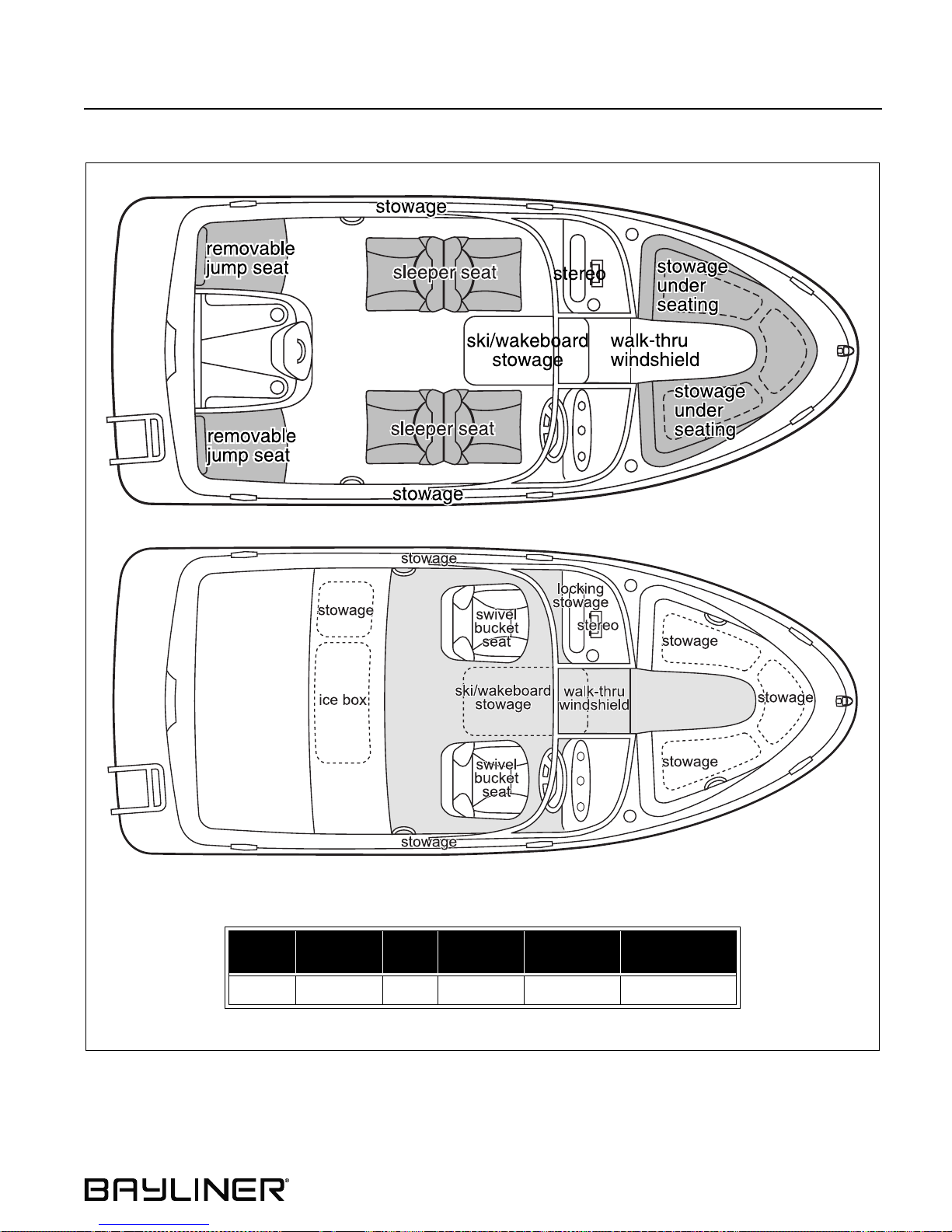
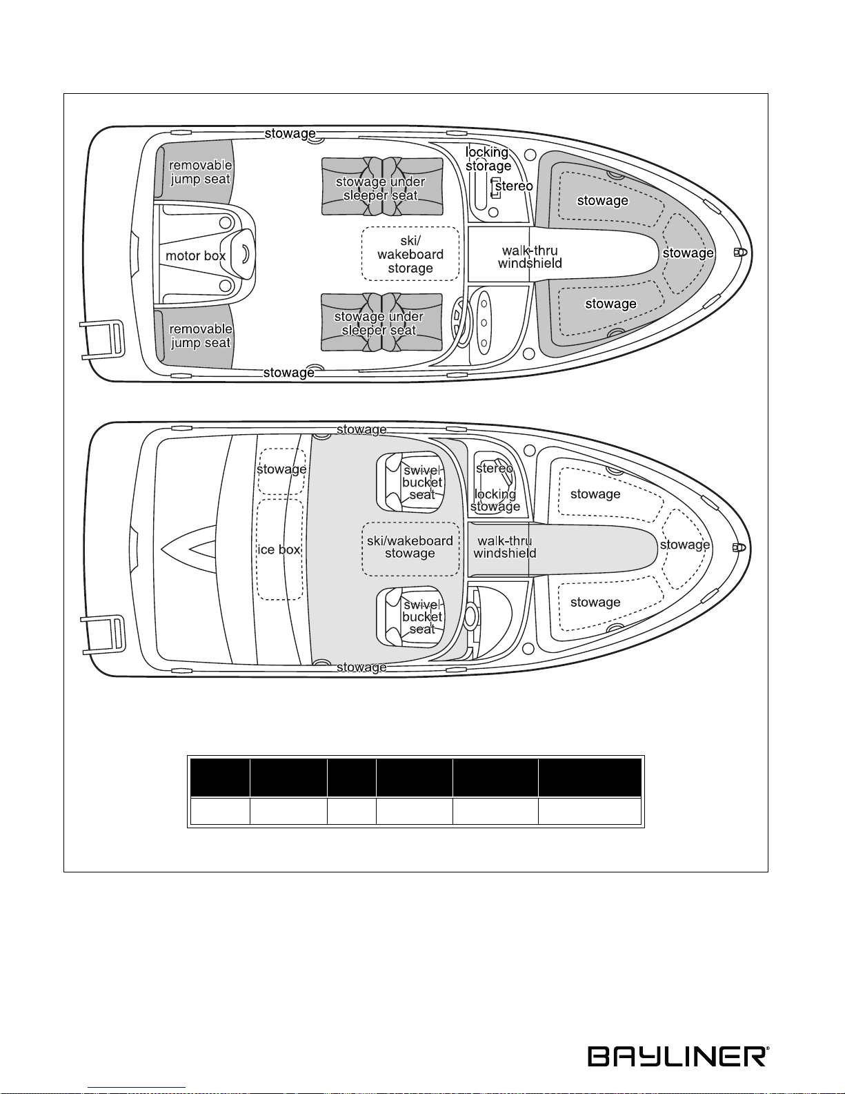
185
Overall
Length
18' 1" 4' 0" 7' 8" 1' 8" 3' 0" 28
Bridge
Clearance
Beam
Draft
(Drive Up)
Draft (Drive
Down)
Fuel Capacity
(gal.)
7
Page 14
Chapter 2: Product Specifications 185, 205 & 225 • Owner’s Manual Supplement
205
Overall
Length
20' 1" 4' 1" 8' 0" 1' 7" 3' 1" 35
Bridge
Clearance
8
Beam
Draft
(Drive Up)
Draft (Drive
Down)
Fuel Capacity
(gal.)
Page 15
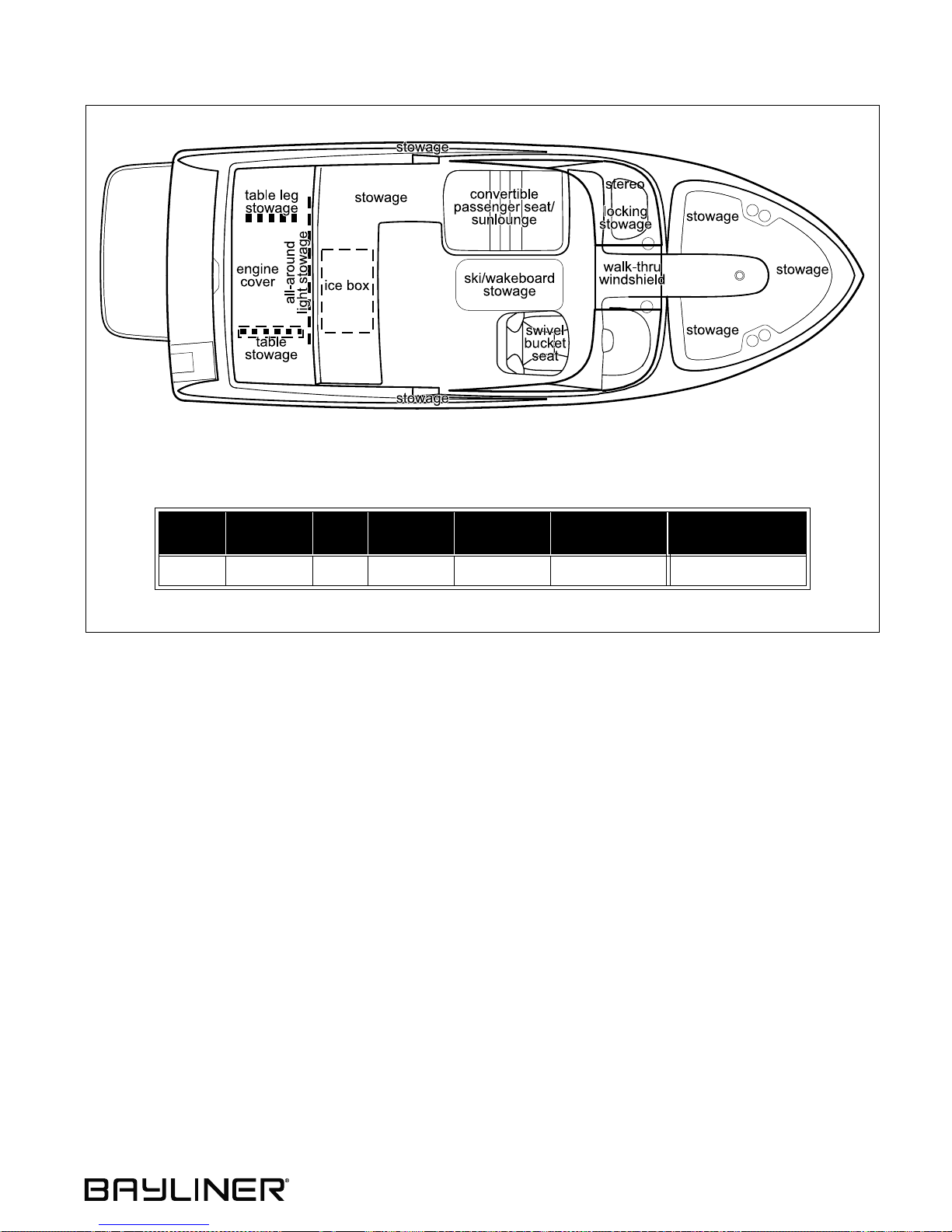
185, 205 & 225 • Owner’s Manual Supplement Chapter 2: Product Specifications
225
Overall
Length
22' 1" 7' 4" 8' 6" 1' 6" 2' 9" 50 10
Bridge
Clearance
Beam
Draft
(Drive Up)
Draft (Drive
Down)
Fuel Capacity
(gal.)
Freshwater T ank
Capacity (gal.)
9
Page 16
Chapter 3: Locations
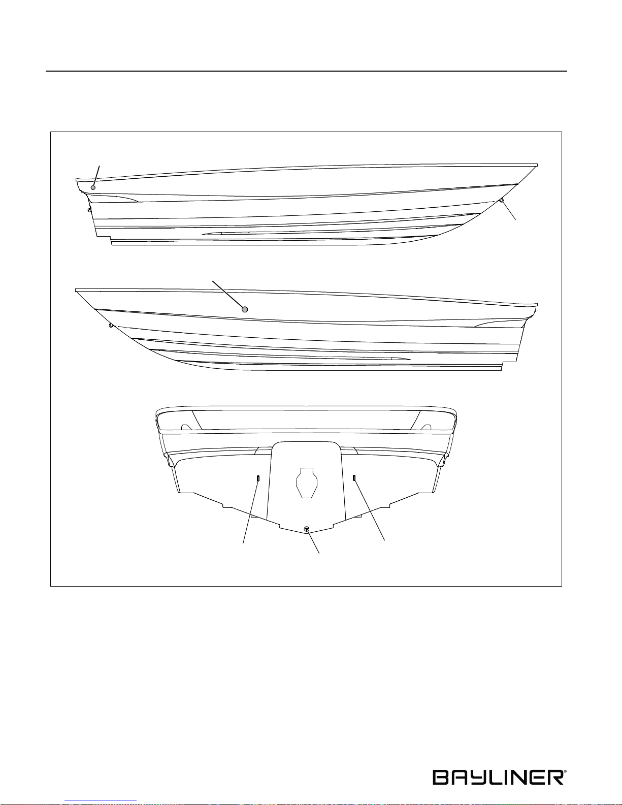
Exterior Views
Hull Views
BILGE PUMP
DRAIN
DASH DRAIN
185, 205 & 225 • Owner’s Manual Supplement
STARBOARD HULLSIDE
BOW EYE
PORT HULLSIDE
STERN EYE
TRANSOM
GARBOARD
DRAIN PLUG
STERN EYE
10
Page 17
185, 205 & 225 • Owner’s Manual Supplement Chapter 3: Locations
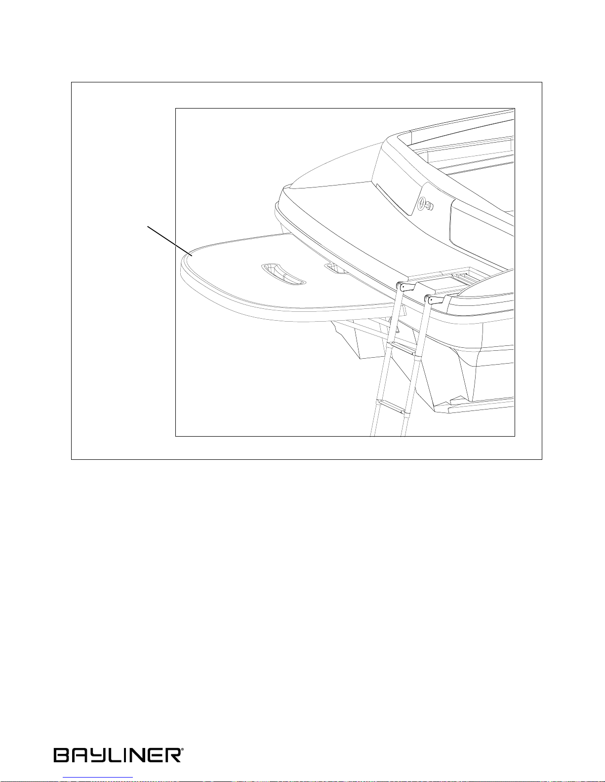
Extended Swim Plat form (If Equipped)
EXTENDED SWIM
PLATFORM
11
Page 18
Chapter 3: Locations 185, 205 & 225 • Owner’s Manual Supplement
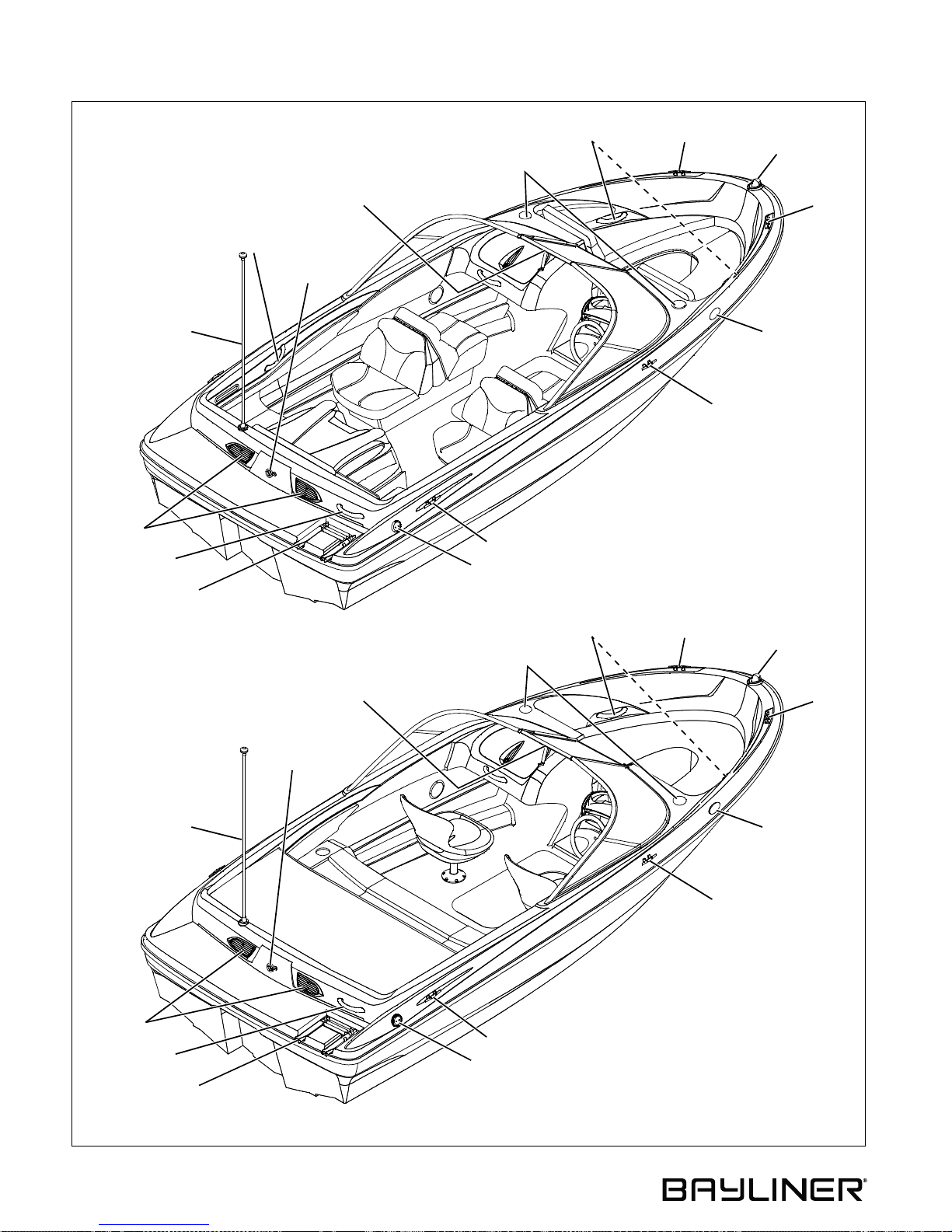
185 Deck View
SLEEPER SEAT LAYOUT
ALL-AROUND LIGHT
(REMOVABLE)
BLOWER
VENTS
GRAB HANDLE
BOARDING LADDER
GRAB
HANDLE
WALK-THROUGH
SKI TOW
RING
WINDSHIELD
GRAB HANDLES
CUPHOLDERS
CLEAT
FUEL FILL/VENT DECK FITTING
CLEAT
BOW LIGHT
CLEAT
HORN
CLEAT
SPORT SEATING LAYOUT
ALL-AROUND LIGHT
(REMOVABLE)
BLOWER
VENTS
GRAB HANDLE
BOARDING LADDER
SKI TOW
RING
WALK-THROUGH
WINDSHIELD
GRAB HANDLES
CUPHOLDERS
CLEAT
FUEL FILL/VENT DECK FITTING
CLEAT
BOW LIGHT
CLEAT
HORN
CLEAT
12
Page 19
185, 205 & 225 • Owner’s Manual Supplement Chapter 3: Locations
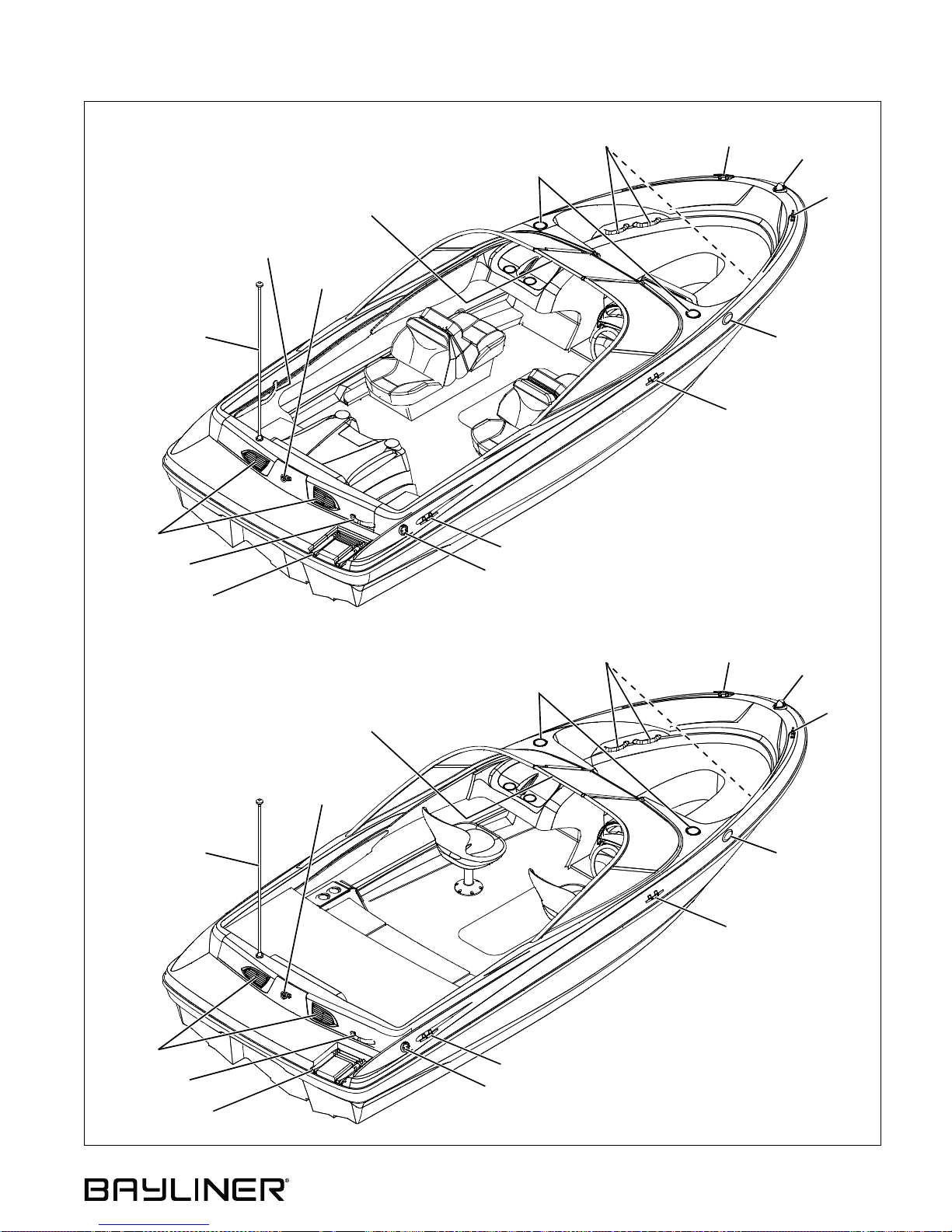
205 Deck View
SLEEPER SEAT LAYOUT
ALL-AROUND LIGHT
(REMOVABLE)
BLOWER
VENTS
GRAB HANDLE
BOARDING LADDER
GRAB
HANDLE
WALK-THROUGH
WINDSHIELD
SKI TOW
RING
GRAB HANDLES
CUPHOLDERS
CLEAT
FUEL FILL/VENT DECK FITTING
CLEAT
CLEAT
BOW LIGHT
CLEAT
HORN
SPORT SEATING LAYOUT
ALL-AROUND LIGHT
(REMOVABLE)
BLOWER
VENTS
GRAB HANDLE
BOARDING LADDER
WALK-THROUGH
WINDSHIELD
SKI TOW
RING
GRAB HANDLES
CUPHOLDERS
CLEAT
FUEL FILL/VENT DECK FITTING
CLEAT
CLEAT
BOW LIGHT
CLEAT
HORN
13
Page 20
Chapter 3: Locations 185, 205 & 225 • Owner’s Manual Supplement
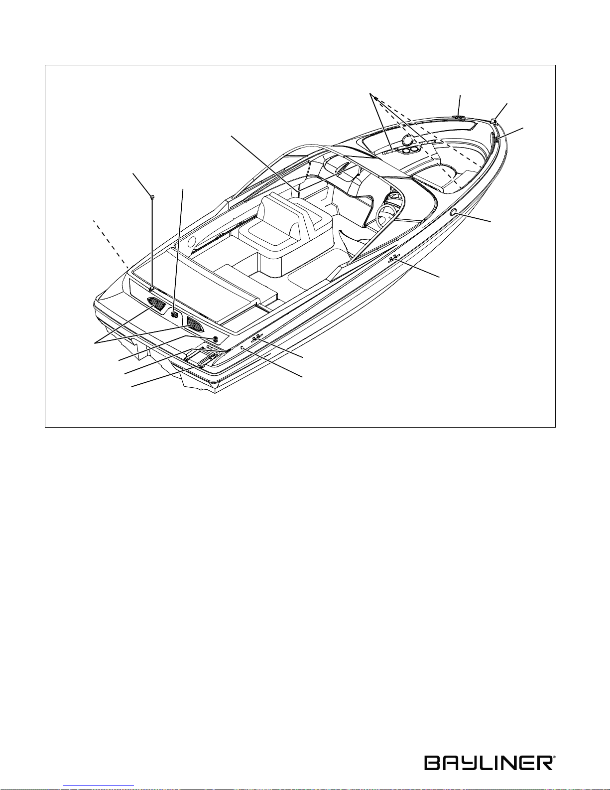
225 Deck View
ALL-AROUND LIGHT
(REMOVABLE)
FUEL FILL/VENT
DECK FITTING
BLOWER
VENTS
FRESHWATER FI L L
DECK FITTING
TRANSOM SHOWER
BOARDING LADDER
SKI TOW
RING
WALK-THROUGH
WINDSHIELD
GRAB HANDLES
CLEAT
FRESHWATER TANK VENT
CLEAT
BOW LIGHT
CLEAT
HORN
CLEAT
14
Page 21
185, 205 & 225 • Owner’s Manual Supplement Chapter 3: Locations
Component Locations
12-Volt Accessory Outlet(s):
• 185 & 205 - On the starboard side dash panel.
• 225 - One next to the CD player and one on the starboard side next to the aft bench seat.
Battery: On the port side of the engine compartment
Bilge Pump: In the engine compartment, forward of the engine.
Engine Circuit Break er : On the engine.
Fresh Water Fill Deck Fitting (225-If Equipped): On the aft deck, above the boarding ladder.
Fresh Water Pump Switch (225-If Equipped): On the starboard side next to the aft bench seat.
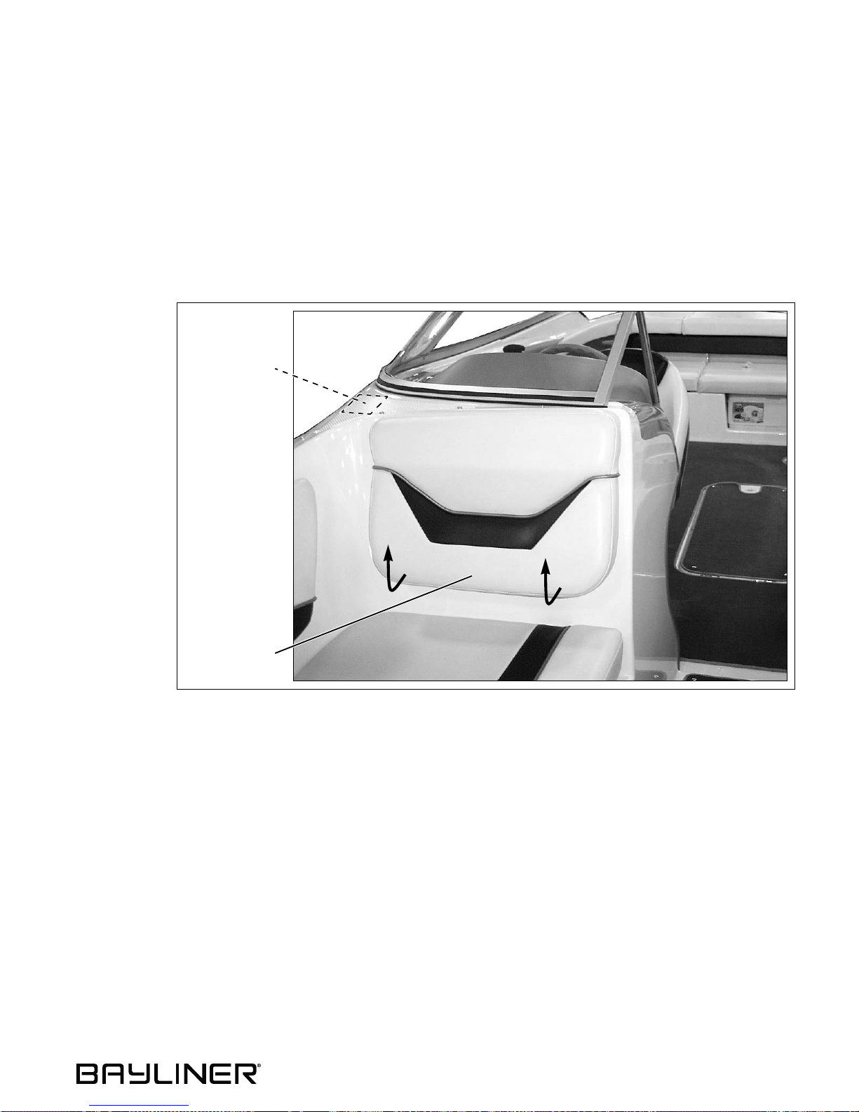
Fuse Block:
Access is
through the
starboard aft
seat back in
the bow
seating area.
FUSE BLOCK
LIFT SEAT BACK
FOR ACCESS TO
FUSE BLOCK
Fuel Fill Deck Fitting:
• 185 & 205 - On the starboard side of the aft deck (see page 10 or 11).
• 225 - On the port side of the aft deck (see page 12).
15
Page 22
185, 205 & 225 • Owner’s Manual Supplement
Chapter 4: Propulsion & Related Systems
Engine
Be sure to read and understand the engine operation and maintenance manuals before starting or doing any maintenance on the engine.
Engine Room Ventilation System
WARNIN G!
!
FIRE/EXPLOSION HAZARD
• Use of the blower system is NOT A GUARANTEE that explosive fumes ha v e been removed.
• If you smell fuel, DO NOT start the engine and DO NOT turn On any electrical devices.
• If you smell fuel and the eng ine i s already running, SHUT OFF the engine and TURN OFF
all electrical devices. Investigate immediately.
• DO NOT obstruct or modify the ventilation system.
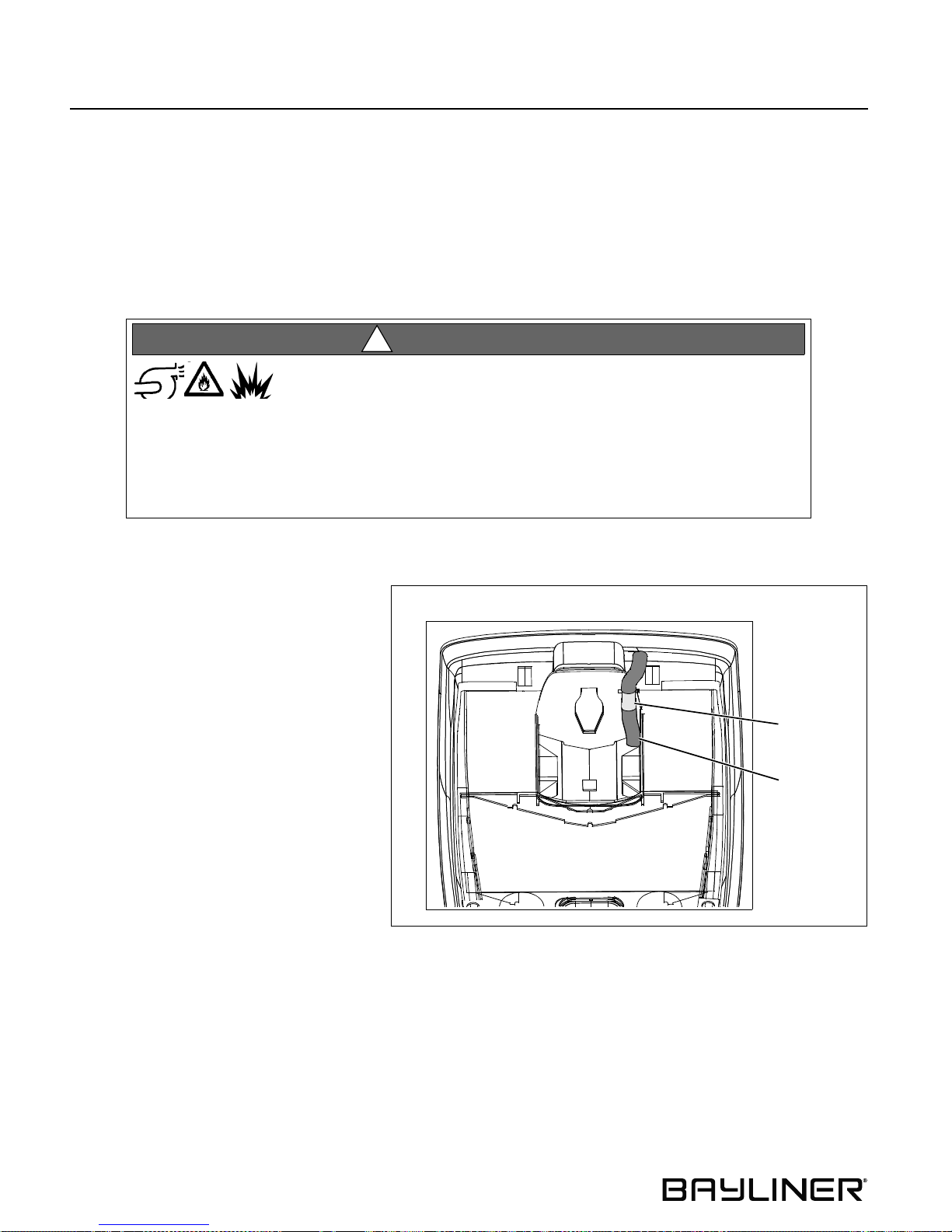
• The bilge blower removes explosive fuel
fumes from the engine compartment.
• Fresh air is drawn into the compartment
through the deck vents.
• The bilge blower switch is at the helm.
To make sure the engine compartment is ventilated wit h fresh air, run the bilg e blower:
• For at least four minutes before starting
the engine.
• During st arting.
• Anytime your boat is running be low
cruising speed.
BILGE BLOWER SYSTEM
BLOWER
BLOWER
HOSE
16
Page 23
185, 205 & 225 • Owner’s Manual Supplement Chapter 4: Propulsion & Related Systems
Fuel System
WARNIN G!
!
FIRE, EXPLOSION AND OPEN FLAME HAZARD!
• It is very important t hat the fuel system be inspect ed thoroughly the first time it is filled and
at each subsequent filling.
• The fueling instructions in the
the engine operation manual must be followed.
Avoid the storage or handling of gear near the fuel li nes, fittings and tank.
Sport Boat Owner’s Manual and the fuel recommendations in
CAUTION
!
Fuel Fill and Vent
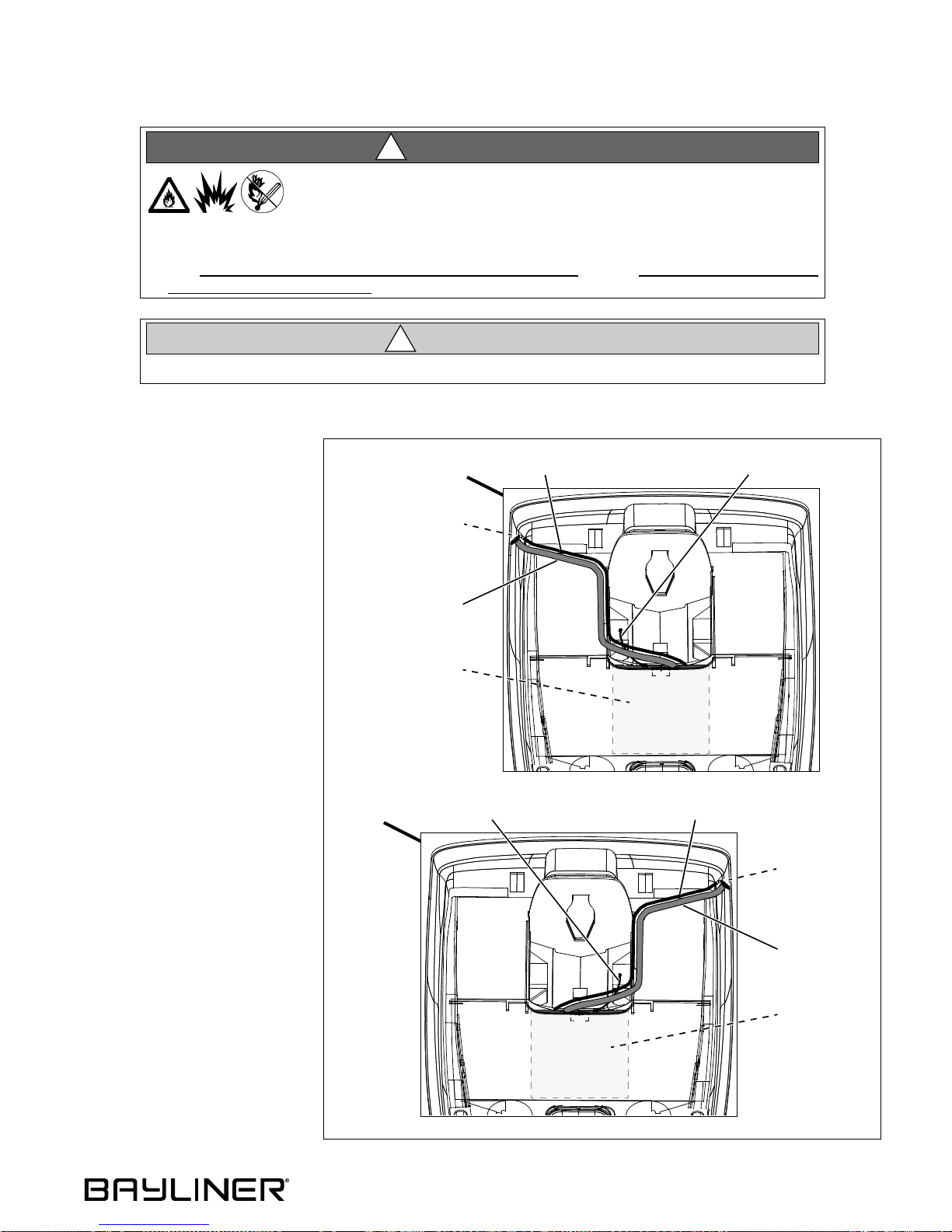
• The fuel fill/vent fitting is
marked “GAS”.
• If you experience difficulty
filling the fuel tank, check to
see if the fuel fill hose is
kinked or collapsed. If there
are no visible signs of a problem, contact your local dealer.
Fuel Filters
• The fuel pickup tube (located
inside the fuel tank) is
equipped with a fine mesh
screen filt er.
• In addition, when supplied by
the engine manufacturer, a
fuel filter is installed on
the engine.
• Periodically replace the fuel
filters to make sure they
remain clean and free
of debris.
• Talk to your selling dealer or
local marina about fuel additives that help prevent fungus
or other buildup in your
fuel tank.
185 & 205
FUEL FILL/VENT
DECK FITTING
FUEL FILL
FUEL TANK
225
HOSE
FUEL LINE
FUEL TANK
VENT HOSE
FUEL TANK
VENT HOSE
FUEL LINE
FUEL FILL/VENT
DECK FITTING
FUEL FILL
HOSE
FUEL TANK
17
Page 24
185, 205 & 225 • Owner’s Manual Supplement
Chapter 5: Controls & Gauges
Steering
• Refer to the engine manu al for steerin g system details.
Shift/Throttle Lever
WARNIN G!
!
LOSS OF CONTROL HAZARD!
Improper maintenance of shift /throttle hardware may cause a sudden loss of control!
• Read and understand all of the information about the shift/throttle in the Sport Boat Owner’s Manual.
• Also, read and understand the shifter/throttle and engine manuals.
Power Trim and Tilt
• The stern drive on your boat is equipped with power trim and tilt.
• Trim and tilt instructions are provided in the engine operation manual and the shifter/throttle manual.
Gauges
Cleaning Gauges
CAUTION
!
PRODUCT or PROPERTY DAMAGE HAZARD!
• Use only mild soap and water to clean the gauge lenses and bez els .
• Use of other cleaners, including common window cle aning s olut ions , ma y cause the l ense s
to crack.
• Lenses cracked in this manner will not be co v ered by our warranty.
Gauge Fogging
• Moisture may occasionally find its way into the gauges causing lens fogging.
• Turning On the gauge lights will help dry the lenses.
• Fogging will not harm the gauges.
Radio Transmission Interference
VHF or other radio tra nsmissions may cause brie f errat ic readi ngs on the tachometer. This will not damage this gauge
or affect its accuracy when not transmitting.
Fuel Gauge
It is normal for the pointer on your fuel gauge to bounce as fuel sloshes back and forth in the fuel tank.
18
Page 25
185, 205 & 225 • Owner’s Manual Supplement
Chapter 6: Plumbing
Bilge Pump
Discharge of oil, oil waste o r fue l i nto navigable waters is prohibited by law. Violators are subject to legal action by the lo cal authorities.
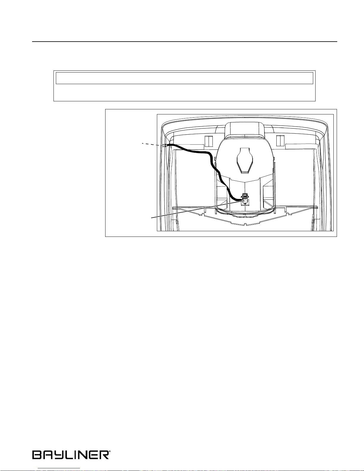
• Your boat is equipped
with a bilge pump for
pumping water out of
the bilge.
• On the 185 & 205 the
bilge pump is controlled by a switch at
the helm.
• On the 225 the bilge
pump is controlled by
an automatic bilge
pump float switch
(auto-float switch) and
a switch at the helm.
THRU-HULL
NOTICE
185 & 205 -
BILGE PUMP ONLY
225 - BILGE PUMP
& FLOAT SWITCH
19
Page 26
Chapter 6: Plumbing 185, 205 & 225 • Owner’s Manual Supplement
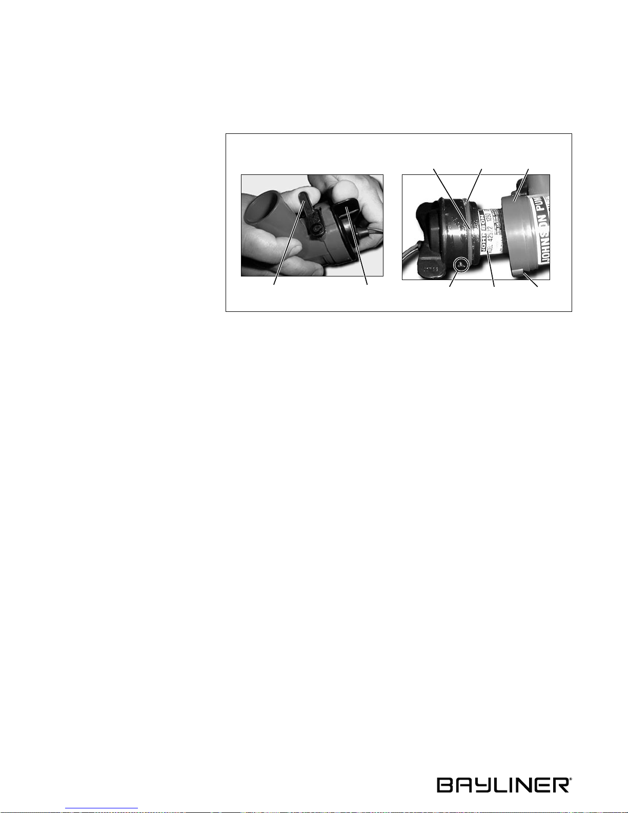
Bilge Pump Testing
• The bilge pump is critical to the safety of your boat.
• Check the bilge pump often to make sure it is working.
Test the pump as follows:
1. Turn On the bilg e pump switch at
the helm.
BILGE PUMP COMPONENTS
LIGHT FILM
OF OIL “O” RING
OUTER
HOUSING
2. Any water in the bilge should
pump overboard.
• If the pump motor is running, but
not pumping, inspect the dis char ge
hose for a kink or collapsed area.
• If no problems a re found, c heck the
bilge pump housing for clogging
debris as follows:
1. Remove the power cartridge:
a. Lift the tab while rotating the
TAB FIN
(TYPICAL)
POWER
CARTRIDGE
SLOTCAM
(TYPICAL)
fins counter-clockwise.
b. Lift out the power cartridge.
c. Clear the outer housing of debris.
2. Reinstall the power cartridge:
a. Make sure the “O” ring is properly seated.
b. C oat the “O” ring with a light film of vegetable or mineral oil.
c. Align the cams on either side of the power cartridge with the two slots on the outer housing.
d. P ress the power cartridge into the housing while twisting clockwise.
3. Check the reinstallation by trying to twist the fins counter-clockwise without lifting the tab; the cartridge should
stay in place.
20
Page 27
185, 205 & 225 • Owner’s Manual Supplement Chapter 6: Plumbing
Auto-float Switch (225 Only )
• The automatic bilge pump uses an electromagnetic float switch (auto-float) to turn on the pump whenever water
rises abov e a preset level in the bilge.
• The auto-float switch is mounted next to the automatic bilge pump.
• The auto-float swit ch i s wir ed directly to the battery and will normally function even when th e boa t is completely
shut down and left unattended.
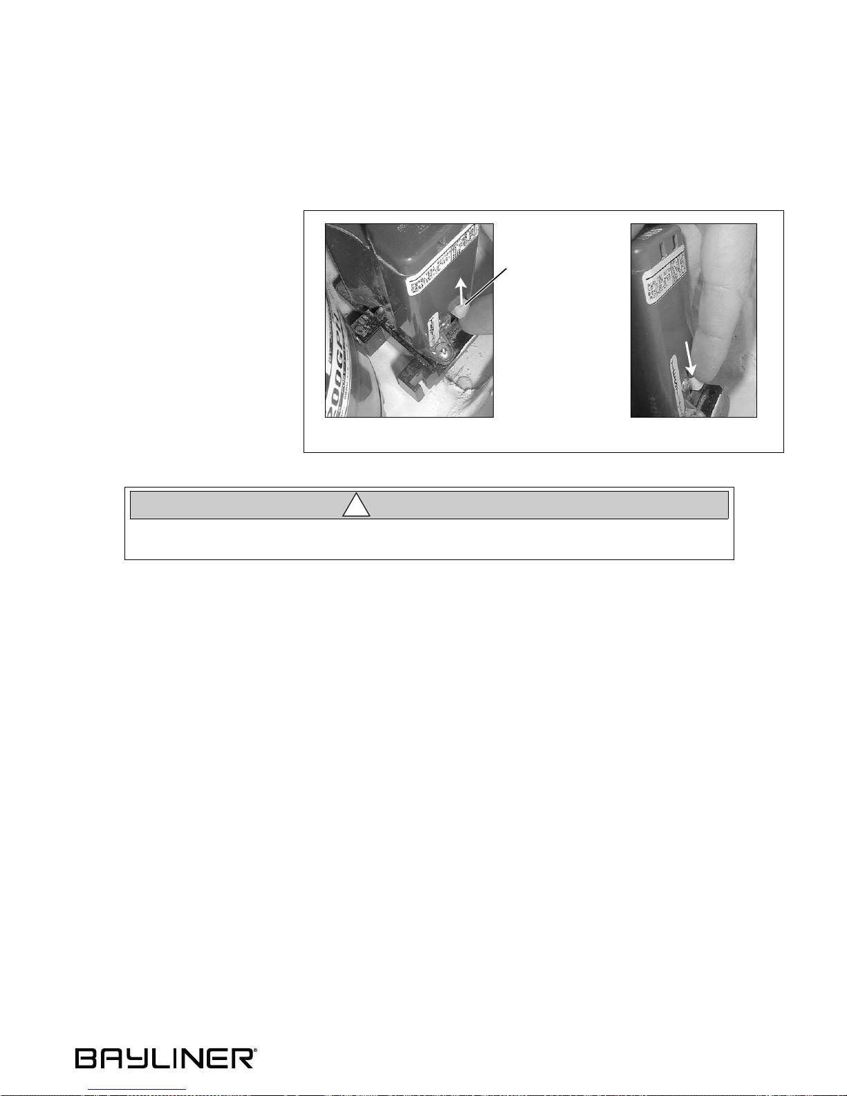
Test the auto-float switch often
as follows:
1. Lift the float switch test button
up to turn On the bilge pump.
• If the pump does not turn On,
check the fuse on the fuse block.
• If the fuse is good but the switch
still doesn’t work, it may mean
the switch is bad or possibly the
battery is low.
2. Push test button all the way
down to return the float switch
to auto mod e.
When the test is completed on the fl oat switch, y ou MUST push the test button all the wa y do wn
to return the swit ch to auto m ode!
FLOAT SWITCH
TESTING
FLOAT SWITCH
TEST BUTTON
LIFT SWITCH UP
BILGE PUMP SHOULD TURN ON BILGE PUMP SHOULD TURN OFF
CAUTION
!
PUSH SWITCH DOWN
21
Page 28
Chapter 6: Plumbing 185, 205 & 225 • Owner’s Manual Supplement
Freshwater Transom Shower (If Equipped - 225 Only)
WARNIN G!
!
• Only use safe drinking (potable) water in your boat’s freshwater system.
• Only use a sanitary drinking water hose to fill the water tank or connect to city water.
• Never use a common garden hose for drinking water.
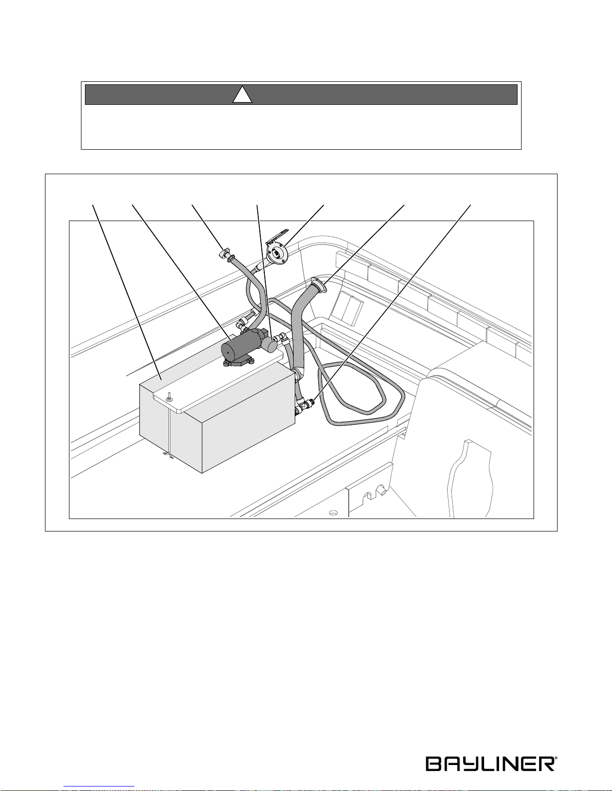
WATER
TANK
WATER
PUMP
WATER TANK VENT WATER FILL
WATER
FILTER
TRANSOM SHOWER WATER TANK
DECK FITTINGDECK FITTING
DECK FITTING DRAIN PLUG
22
Page 29
185, 205 & 225 • Owner’s Manual Supplement Chapter 6: Plumbing
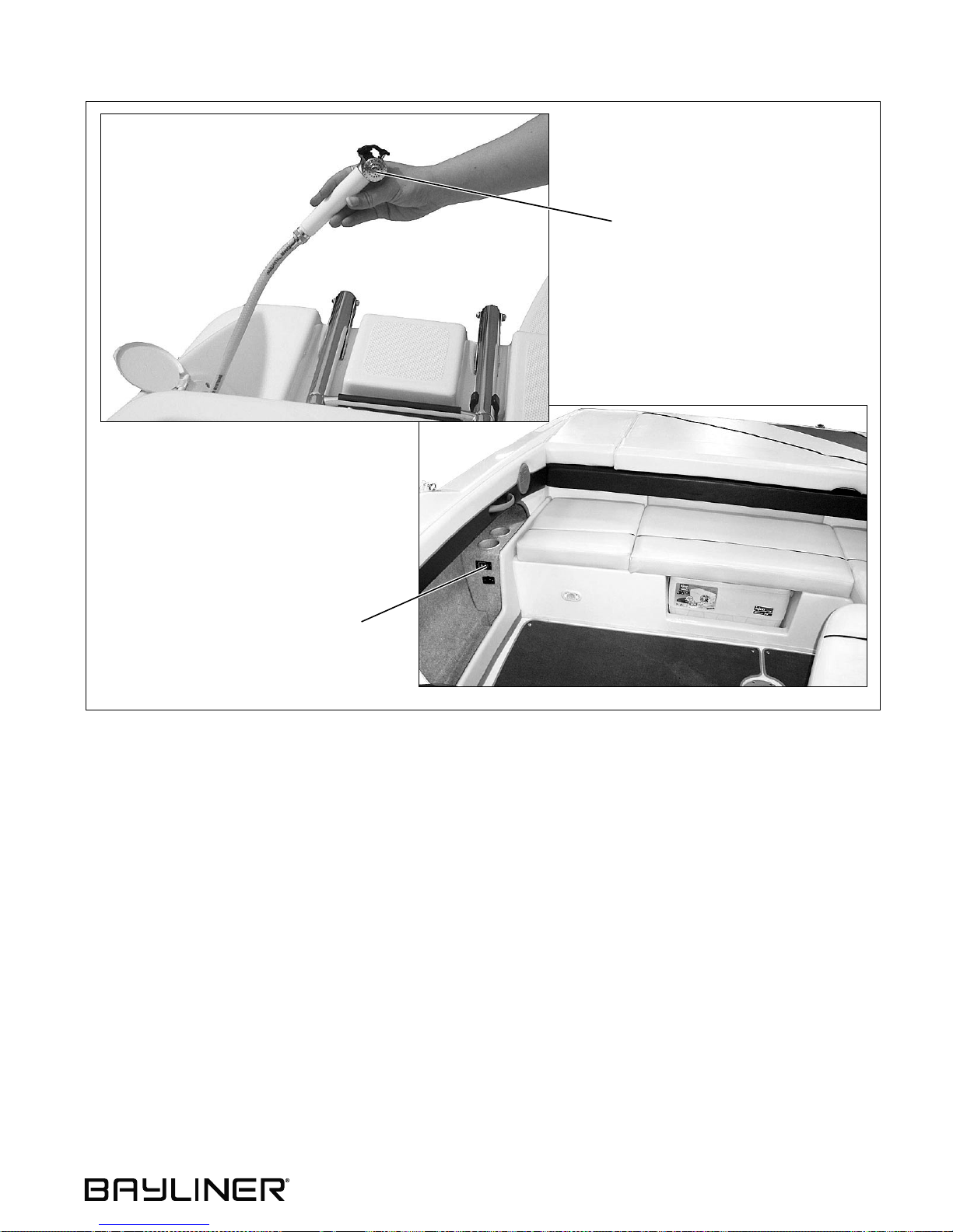
TRANSOM SHOWER
FRESHWATER PUMP SWITCH
• Read the Freshwater System section in the Sport Boat Owner’s Manual.
• Your boat is equipped with a pressure type (demand) freshwater (potable) system.
• This system is pressurized by turning On the freshwater pump switch.
Observe the following about the freshwater system:
• Turn the freshwater pump switch Off when the boat is not in use or the water tank is empty.
• Inspect and clean the water filter often (located on the water pump).
• When your boat is to be left unattended for long periods of time, pump the water tank dry to prevent stored water
from becoming stagnant and distasteful.
• If the freshwater s ystem nee ds to be di sinf ected , ask y our deal er abou t trea tmen ts avai labl e for yo ur boat’s system.
• To winterize the freshwater system, pump the water tank dry and drain the system by opening the water filter.
23
Page 30
Chapter 7: Deck Equipment
Cleats and Tow Eyes
WARNIN G!
!
PERSONAL INJURY and /or PRODUCT or PROPERTY DAMAG E HAZARD!
• NEVER lift the boat using the bow and ster n eyes or the cleats.
Carefully read the section on towing in the Sport Boat Owner’s Manual before:
• Towing anything behind the boat.
• Being towed by another vessel.
Ski Tow Ring
185, 205 & 225 • Owner’s Manual Supplement
WARNIN G!
!
PERSONAL INJURY and /or PRODUCT or PROPERTY DAMAG E HAZARD!
Failure to follow these guidelines can result in inj ury or deat h:
• Only tow water skis, wakeboards, or recreational towables.
• Do not tow parasai ls , kit es, or othe r boats.
• Do not tow mor e t han t wo pe rsons at one ti me.
• Use caution with skier in tow as tow rope may snap back into cockpit when released.
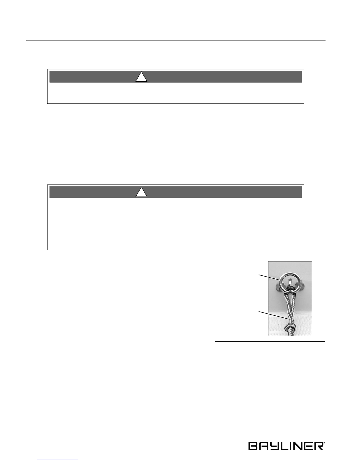
Your boat has a ski tow ring. Attach tow rope as shown in the photo.
SKI TOW RING
SKI TOW ROPE
24
Page 31
185, 205 & 225 • Owner’s Manual Supplement Chapter 7: Deck Equipment
Ski-Tow Tower (If Equipped)
WARNIN G!
!
PERSONAL INJURY and /or PRODUCT or PROPERTY DAMAG E HAZARD!
Failure to follow these guidelines can result in inj ury or deat h:
• Read all warning labels on ski-tow tower.
• Before each use, make sure all bolts are in place and tight.
• Only tow water skis, wakeboards, or recreational towables.
• Do not exceed the following maximum tow weights:
185 model - 400 pounds
205 & 225 models - 600 pounds
• Do not tow parasai ls , kit es, or othe r boats.
• Do not tow mor e t han t wo pe rsons at one ti me.
• Do not climb on, sit o n, sta nd on, jump off or dive off tower.
• Never allow passengers to sit behind tow r ope at tac hment poi nt.
• Use caution with skier in tow as tow rope may snap back into cockpit when released.
• Never allow loose tow rope ends to dangle off tower.
• When tower is up, watch for lo w obs tacl es s uch as tree limbs, bridges, or power lines.
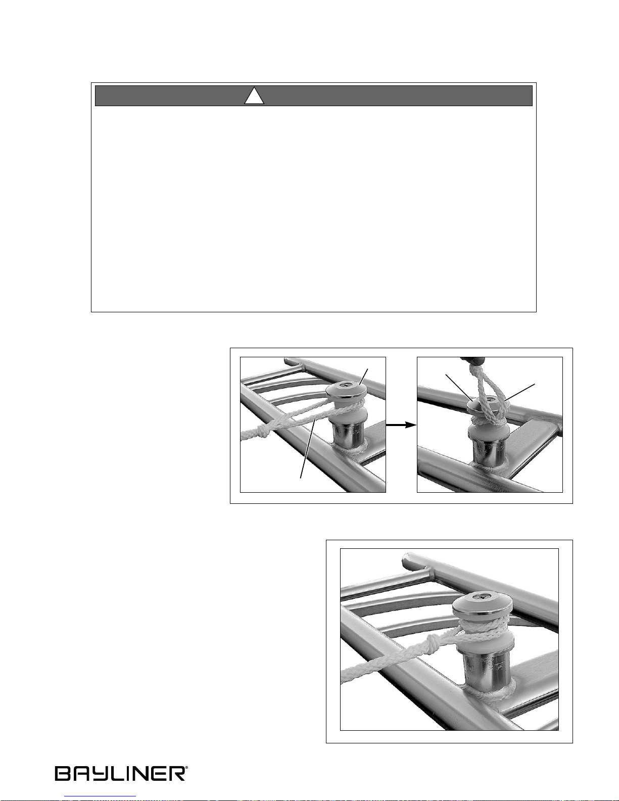
Attaching the Ski -Tow Rope
1. Place the ski-tow rope loop (A)
over the ski-tow pylon (B).
2. Put a twist in the ski- tow rope
loop (A) and place over the skitow pylon (B) again.
3. Pull ski-tow rope to tighten.
B
12
A
B
A
3
25
Page 32
Chapter 7: Deck Equipment 185, 205 & 225 • Owner’s Manual Supplement
Folding Ski-Tow Tower (205 & 225 Only)
WARNIN G!
!
PERSONAL INJURY and /or PRODUCT or PROPERTY DAMAG E HAZARD!
• Folding or unfol ding the ski-tow tower is a two person task.
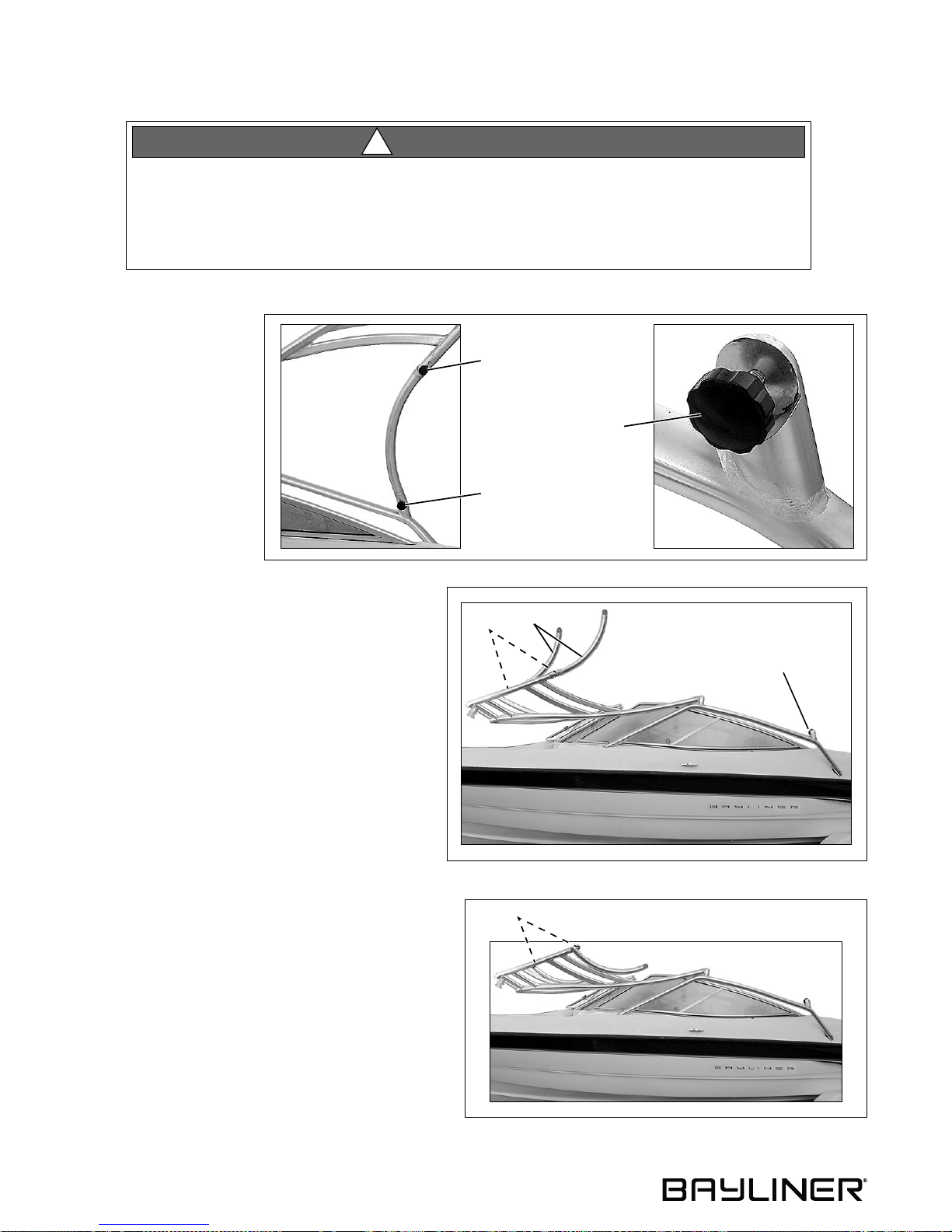
• Before each use of the folding ski-tow tower, make sure all four lock-down bolts are
tightened firmly.
• Read all war n i ng l abels on the ski- tow tower.
To fold the ski-tow tower
into the storage position:
1. Remove the lower
B
lock-down bolt (A) on
each side of the tower.
LOCK-DOWN BOLT
(TYPICAL, 4 - PLACES)
2. Carefully fold the tower forward.
3. Replace the lower lock-down bolts (A).
4. Remove the upper lock-down bolts (B).
5. Lower the support legs (C).
6. Replace the upper lock-down bolts (B).
A
C
B
A
B
To return the tower to the towing position, perform the
above steps in reverse order.
26
Page 33
185, 205 & 225 • Owner’s Manual Supplement Chapter 7: Deck Equipment
Canvas (If Equipped)
CAUTION
!
PRODUCT or PROPERTY DAMAGE HAZARD!
Take down and securely stow the canvas top or bimini top, side curtains, and slant back cov er
before transporting your boat by road.
NOTICE
Two people are needed to do the tasks listed belo w and o n the following pages in this section.
Convertible Top
H
E
G
F
K
C
J
B
I
A
D
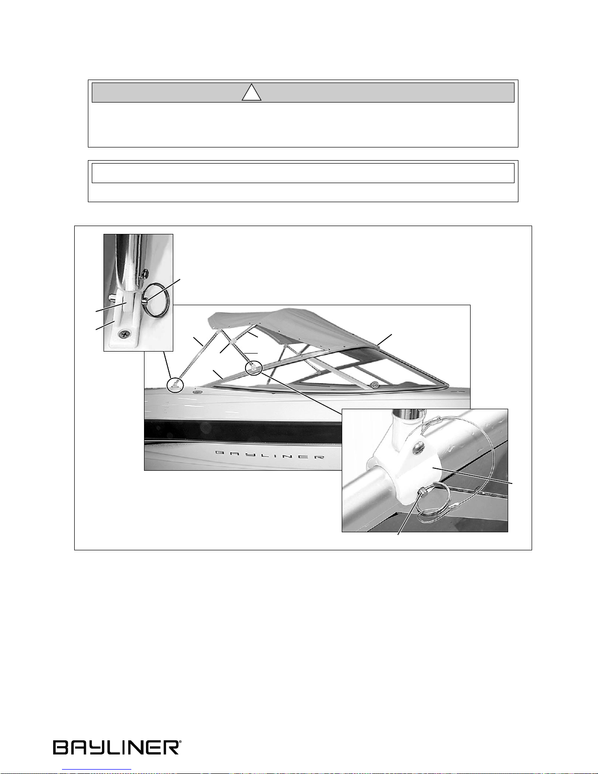
1. Unzip, remove, and stow the storage boot.
2. Slide the swivel ends (A) of the main bow (B) over the pre-drilled hole on each side windshield frame (C) and
secure with the pins (D).
3. Insert the end eyes (E) of the aft braces (F) into the deck hinges (G) and secure them with the pins (H).
4. Unfold the canvas top and snap the front edge of the top (I) to the windshield frame.
5. Align the secondary bow (J) with the center seam of the canvas by loosening or tightening the top straps.
6. No adjustments to the jaw slides (K) should be needed as they are preset during manufacturing. Before attemp t-
ing to adjust the jaw slide positions, obtain the correct measurements from your selling dealer.
7. If additional canvas (i.e. side curtains or slant back cover) is installed, the canvas top may need readjustment to
align the snaps on the canvas with the snaps on the boat.
27
Page 34
Chapter 7: Deck Equipment 185, 205 & 225 • Owner’s Manual Supplement
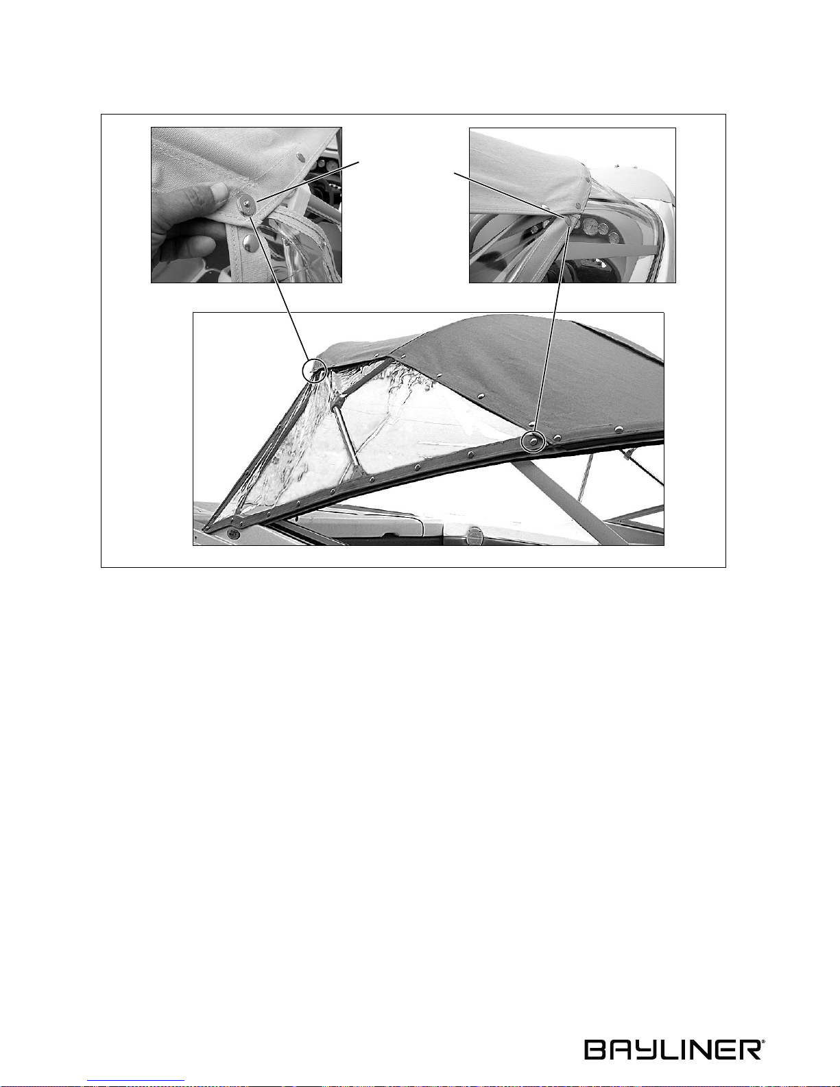
Side Curtains (If Equipped)
B
A
1. Snap the forward corner of the side curtain (A) t o the windshield frame.
2. Working your way aft, alternately snap the top snaps to the canvas top and the bottom snaps to the windshield
frame and deck.
3. Insert the side curtain stud into the socket on the canvas top.
28
Page 35
185, 205 & 225 • Owner’s Manual Supplement Chapter 7: Deck Equipment
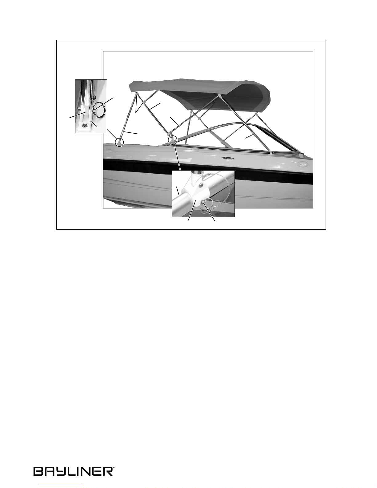
185 Bimini Top (If Equipped)
H
E
G
K
F
B
I
J
C
A
D
1. Slide the swivel ends (A) of the main bow (B) over the pre-drilled holes in the windshield frames (C) and insert
the pins (D).
2. Insert the end eyes (E) of the aft braces (F) into the deck hinges (G) and secure them with the pins (H).
3. Pull the secondary bow (I) forward and insert the end eyes of the forward braces (J) into the deck hinges and
secure them with the pins.
4. No adjustments to the jaw slides (K) should be needed as they are preset during manufacturing. Before attemp ting to adjust the jaw slide positions, obtain the correct measurements from your selling dealer.
29
Page 36
Chapter 7: Deck Equipment 185, 205 & 225 • Owner’s Manual Supplement
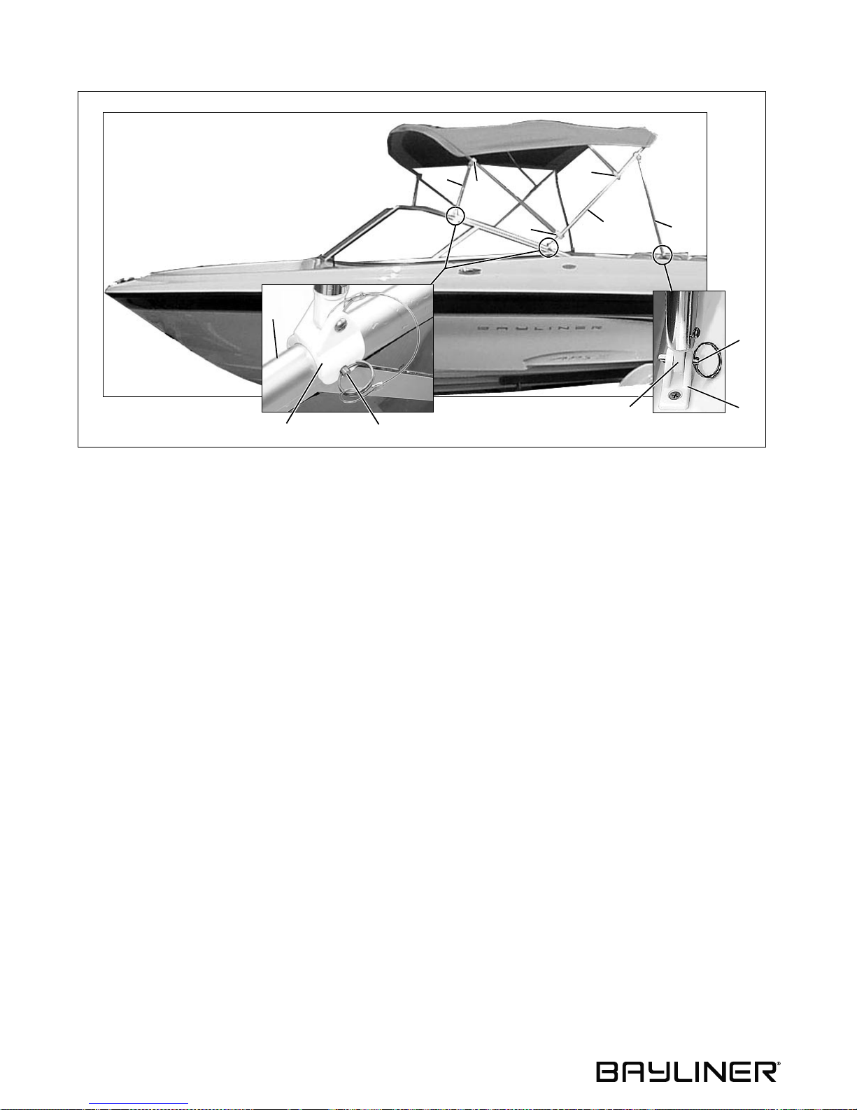
205/225 Bimini Top (If Equipped)
E
J
J
C
A
D
J
B
F
G
I
H
1. Slide the swivel ends (A) of the main bow (B) over the aft pre-drilled holes in the windshield frames (C) and
insert the pins (D).
2. Unfold the canvas top and slide the swivel ends of the forward legs (E) over the forward pre-drilled holes in the
windshield frames and insert the pins.
3. Slide the end eyes (F) of the aft legs (G) into the deck hinges (H) and insert the pins (I).
4. No adjustments to the jaw slides (J) should need to be made as they are preset during manufacturing. Before
attempting to adjust the jaw slide positions, obtain the correct measurements from your selling dealer.
30
Page 37
185, 205 & 225 • Owner’s Manual Supplement Chapter 7: Deck Equipment
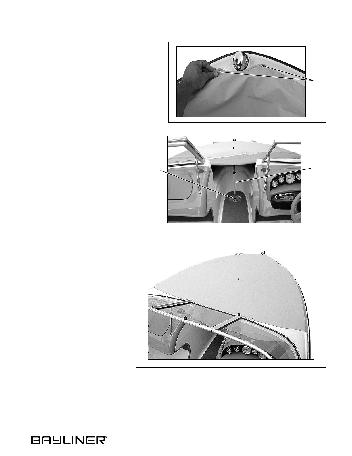
Bow Cover (If Equippe d)
1. Snap the two forward snaps (A) to the deck.
2. Snap the bow cover to the entire port side.
A
3. On the starboard side, onl y snap th e forward half of the bow cover to the deck.
4. Insert the adjustable, center support
pole (B) into both the bow cover and
the table ba se (C).
5. Adjust the support pole so that it is just
C
B
high enough to stay inserted in the
bow cover.
6. Snap the rest of the bow cover to
the deck.
7. Adjust the support pole to take any
slack out of the bow cover.
31
Page 38

185, 205 & 225 • Owner’s Manual Supplement
Chapter 8: Entertainment Systems
Audio System
NOTICE
AM radio reception may be impaired anytime the engine is running.
Read and understand the instruction manual for your boat’s audio system before using.
32
Page 39
185, 205 & 225 • Owner’s Manual Supplement
Chapter 9: Convertible Seats, Beds, & Tables
Sleeper Seats (If Equipped - 185/205 Only)
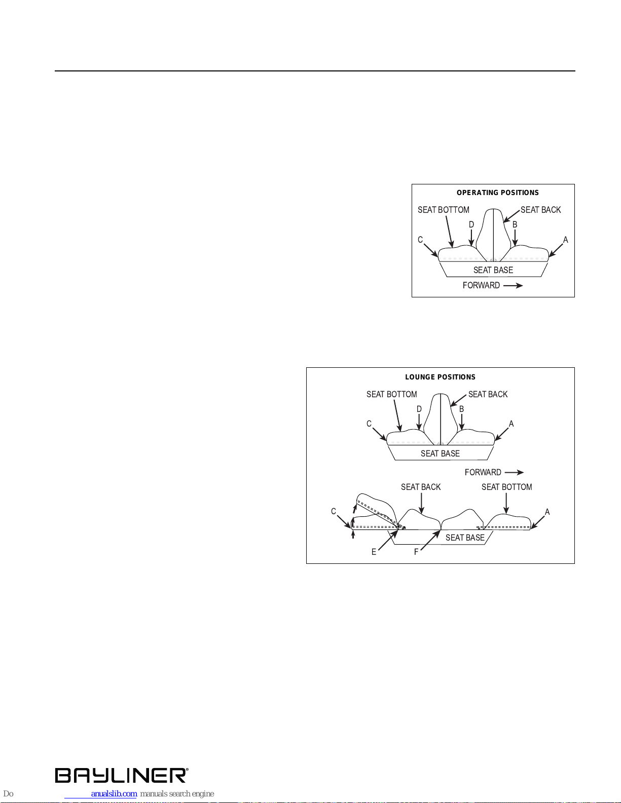
• The sleeper seats can be adjusted fore and aft in the upright, operating position.
• The seat bottoms adjust into backrests when the seats are in the lounge position.
Operating Positions
To slide the seat forward:
1. Lift the forward seat at point (A).
2. Push down on the forward seat at point (B) and pull the seat forward.
3. Lock the forward seat into the desire d posi ti on by p ushing down at
point (A).
4. Lift the aft seat at point (C).
5. Push down on the aft seat at point (D) and push the seat forward until the
aft seat back is flush against the forward seat back.
6. Lock the aft seat into position by pushing down at point (C).
To slide the seat aft, repeat the steps above, but start with the aft seat.
Lounge position s
To adjust into the flat lounge position:
1. Lift the forward seat at point (A).
2. Push down on the forward seat at point (B) and
pull the seat forward unt il the seat ba ck and bottom
SEATBOTTOM SEAT BACK
are flat.
3. Lift the aft seat at point (C).
C A
4. Push down on the aft seat at point (D) and pull the
seat aft until the seat back and bottom are flat.
To adjust into the chaise lounge position:
1. Lift up on the forward or aft seat bottom at point
(A or C) and push the seat bottom down into the
C
locked position.
2. T o lower the seat b ottom, lif t the seat at point (A or
C). Drop the seat bottom flat while holding th e seat
down at point (E).
EF
OPERATING POSITIONS
SEATBOTTOM SEATBACK
D
C A
SEATBASE
FORWARD
LOUNGE POSITIONS
D
SEATBASE
SEATBACK
B
FORWARD
SEATBOTTOM
SEATBASE
B
A
To return the seats to the operating position:
1. Lift the seat backs at point (F) and push down on the back edge of the seat bottom (B) and then seat bottom (D).
2. Push the seat bottoms towards the center of the seat until the seat backs are flush against each other and locked
into place.
33
Page 40
Chapter 9: Convertible Seats, Beds, & Tables 185, 205 & 225 • Owner’s Manual Supplement
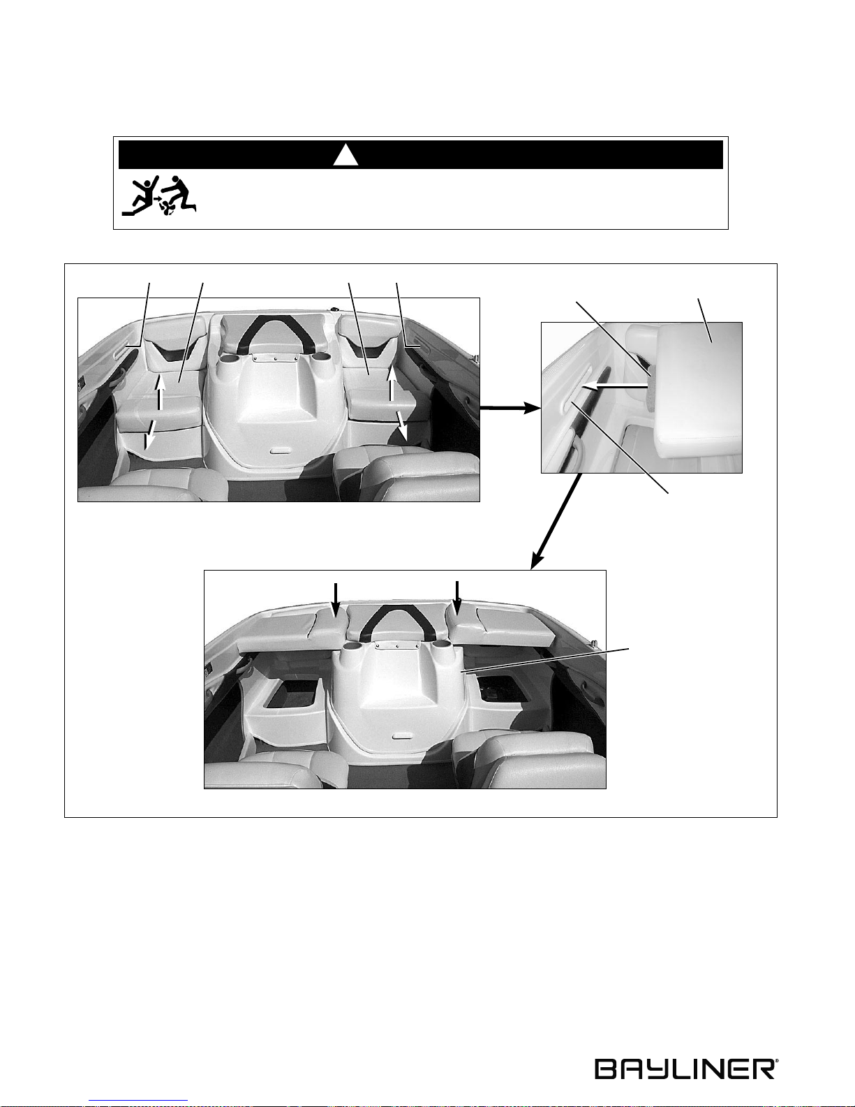
Jump Seat To Sunlounge Conversion (If Equipped - 185/205 Only)
DANGER!
!
PERSONAL SAFETY HAZARD!
DO NOT allow anyone to ride the aft sunlounge cushions while underway or any-
time the engine is running.
AACC
B
A
D
1. Remove the jump seats (A) by lifting and pulling on their forward edges.
2. Rotate each jump seat so that the lounge support tabs (B) face the support slots (C).
3. Slide the lounge support tabs into the support slots.
4. Press down firmly on the inboard side of each jump seat until they rest on the motorbox (D).
C
34
Page 41
185, 205 & 225 • Owner’s Manual Supplement Chapter 9: Convertible Seats, Beds, & Tables
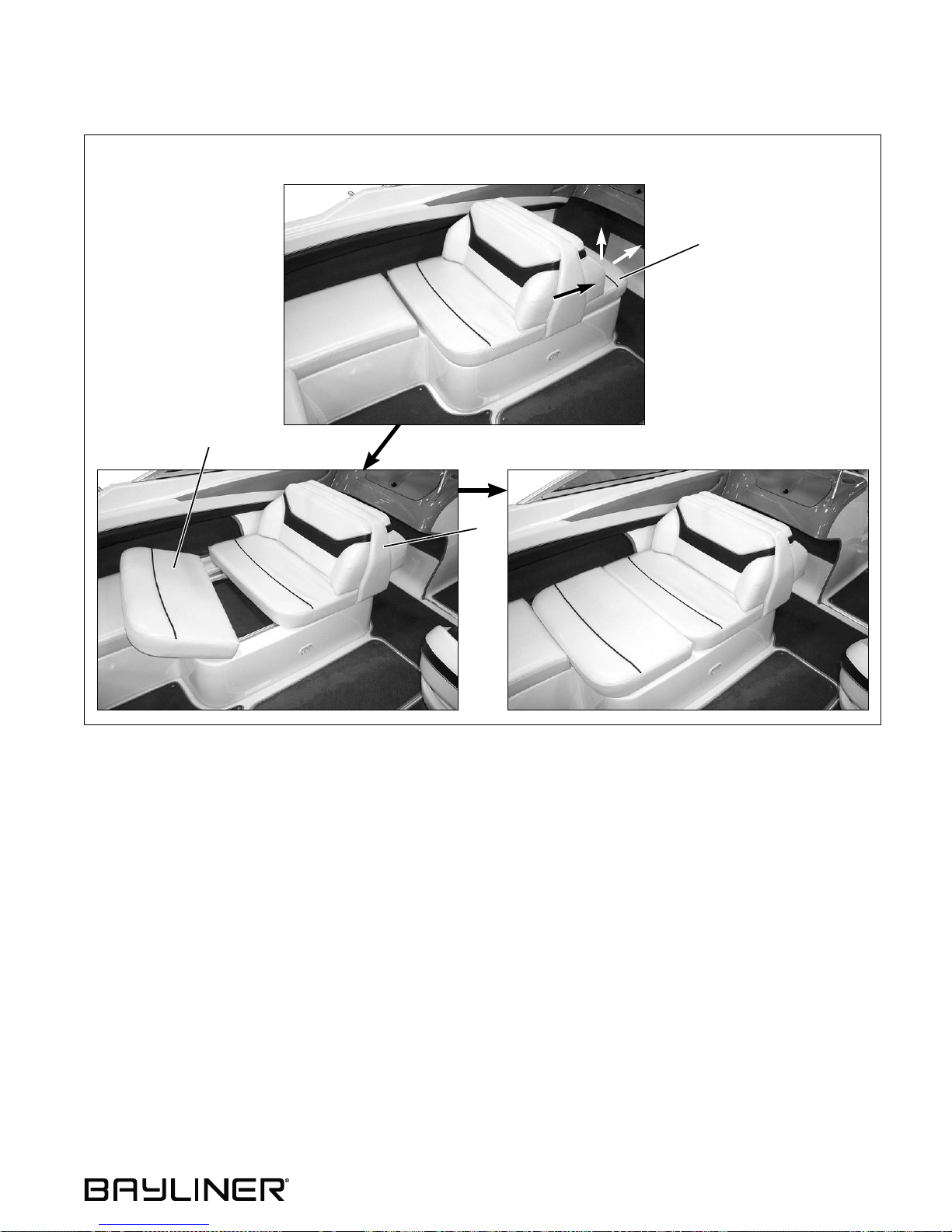
Passenger Seat to Lounge Conversion (225 Only)
PASSENGER SEAT POSITION
A
A
LOUNGE POSITION
B
1. Remove the forward seat bottom (A) by lifting and pulling the forward edge.
2. Slide the seat backs (B) forward until they stop.
3. Use the seat bottom (A) to fill in the space.
35
Page 42
Chapter 9: Convertible Seats, Beds, & Tables 185, 205 & 225 • Owner’s Manual Supplement
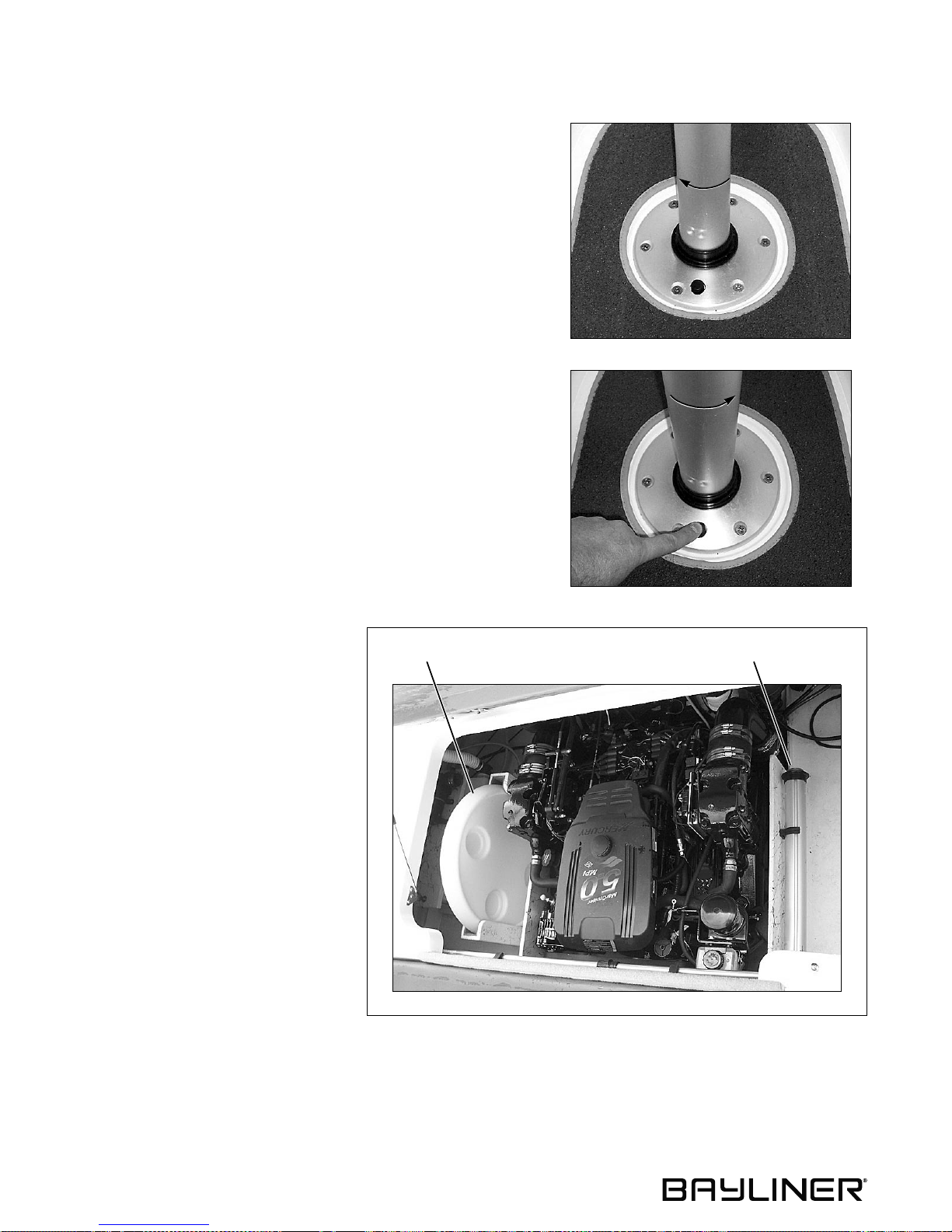
Installing & Removing Table Leg (225 Only)
Installing the Table Leg
1. Place the threaded end into the base..
2. Twist the table leg clockwise until it locks in place.
Removing the Table Leg
1. Press firmly on the black release button and twist the table
leg counter-clockwise.
Table & Table Leg Stowage
When not in use the table and table leg
can be stowed in the engine compar tment.
TABLE LEGTABLE
36
Page 43

185, 205 & 225 • Owner’s Manual Supplement
Chapter 10: Lights
Care and Maintenance
All of the lights installed on your boat ar e of top quality, but you s houl d be a w ar e th at failure may periodical ly occur
for a variety of reasons:
1. There may be a blown fuse - replace the fuse.
2. The bulb may be burned out - carry spare bulbs for replacement.
3. A wire may be damaged or may have come loose - repair as required.
4. The bulb base may be corroded - clean the base and coat it with non-conductive electrical lubricant.
Navigation Lights
CAUTION
Avoid the storage of gear where it would block navigation l ig h ts f rom view.
!
Read and understand the navigation light section of Sport Boat Owner’s Manual.
37
Page 44

Chapter 11: Electrical System
DANGER!
!
EXTREME FIRE, SHOCK & EXPLOSION HAZARD!
• To minimize the risks of fire and explosion, NEVER install knife switches or other arcing
devices in the fuel compartments .
• NEVER substitute automotive parts for marine parts. Electrical, ignition and fuel system
parts were designed and manufactured to comply with rules and regulations that minimize
risks of fire and explosion.
• DO NOT modify the electrical systems or rele vant drawings.
• Have qualif ie d perso nnel i nst all batteries and/or perform electrical system maintenance.
WARNIN G!
!
FIRE & EXPLOSION HAZARD!
• Visually and by smell (s nif f te st) , che ck the engine and fuel compartments for fumes or
accumulation of fuel.
• Minimize the danger of fire and explosion by not exposing the batteries to open flame or
sparks. NEVER smoke anywhere near the batteri es.
185, 205 & 225 • Owner’s Manual Supplement
CAUTION
!
SHOCK & ELECTRICAL SYSTEM DAMAGE HAZARD!
NEVER disconnect the battery cables while th e eng ine i s runni ng si nce i t c an cause
damage to your boat’s electrical system components.
NOTICE
Electrical connections ar e prone to corros ion. To reduce corrosion caused electrical problems,
keep all electrical connect ions clean and apply a spray -on prote ctant that is des igned to pr otect
connections from corr osion.
38
Page 45

185, 205 & 225 • Owner’s Manual Supplement Chapter 11: Electrical System
12-Volt DC System
Battery
The battery supplies electricity for lights, accessories, and engine starting.
The Electrical section of Chapter 8, in the Sport Boat Owner’s Manual, provides battery care and
maintenanc e instruction s.
Fuses and Circu it Breakers
• Fuses for the engine and main accessory power are on the fuse block behind the dash.
• Some equipment may have secondary fuse protection at the unit, or at the battery.
• Electronics power is provided at the helm station.
Alternator
The engine alternator will keep the battery properly charged when running at cruising speeds.
12-Volt Accessory Outlet(s )
CAUTION
!
DO NOT use the 12-volt accessory outlet wi th a c igar ett e or cigar lighter. High temperatures
may melt the outlet.
• Your boat is equipped with one or more 12-volt accessory outlets.
• The outlet(s) can be used with any 12-volt device which draws 10 amps or less.
• Each 12-volt accessory outlet is protected by a 10 amp fuse on the main fuse block.
39
Page 46
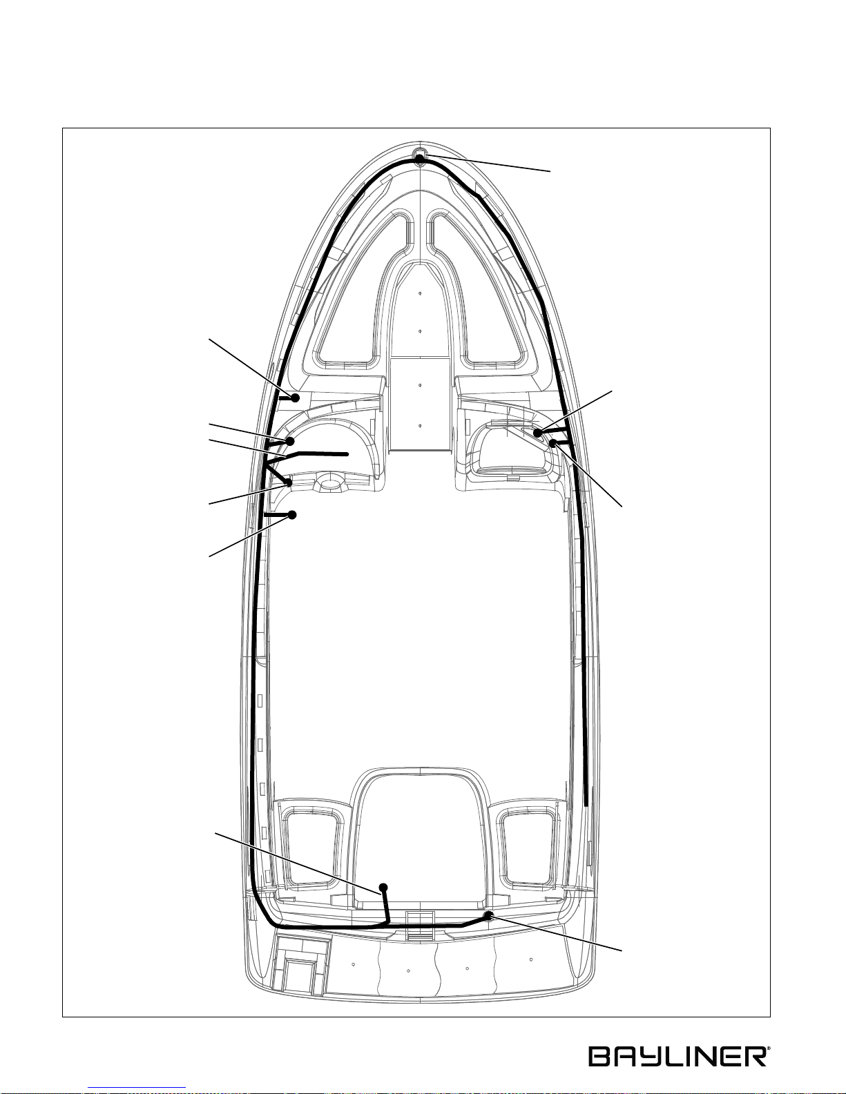
Chapter 11: Electrical System 185, 205 & 225 • Owner’s Manual Supplement
Electrical Routings
185 & 205 Deck Ele ctrical Harnes s
NOTE: VIEW IS UNDERSIDE OF DECK
HORN
12 VOLT OUTLET
DASH HARNESS
SPEAKER
TRIM/TILT SWITCH IN
SHIFT/THROTTLE LEVER
BOW LIGHT
STEREO
SPEAKER
ENGINE PLUG
40
ALL AROUND LIGHT
Page 47
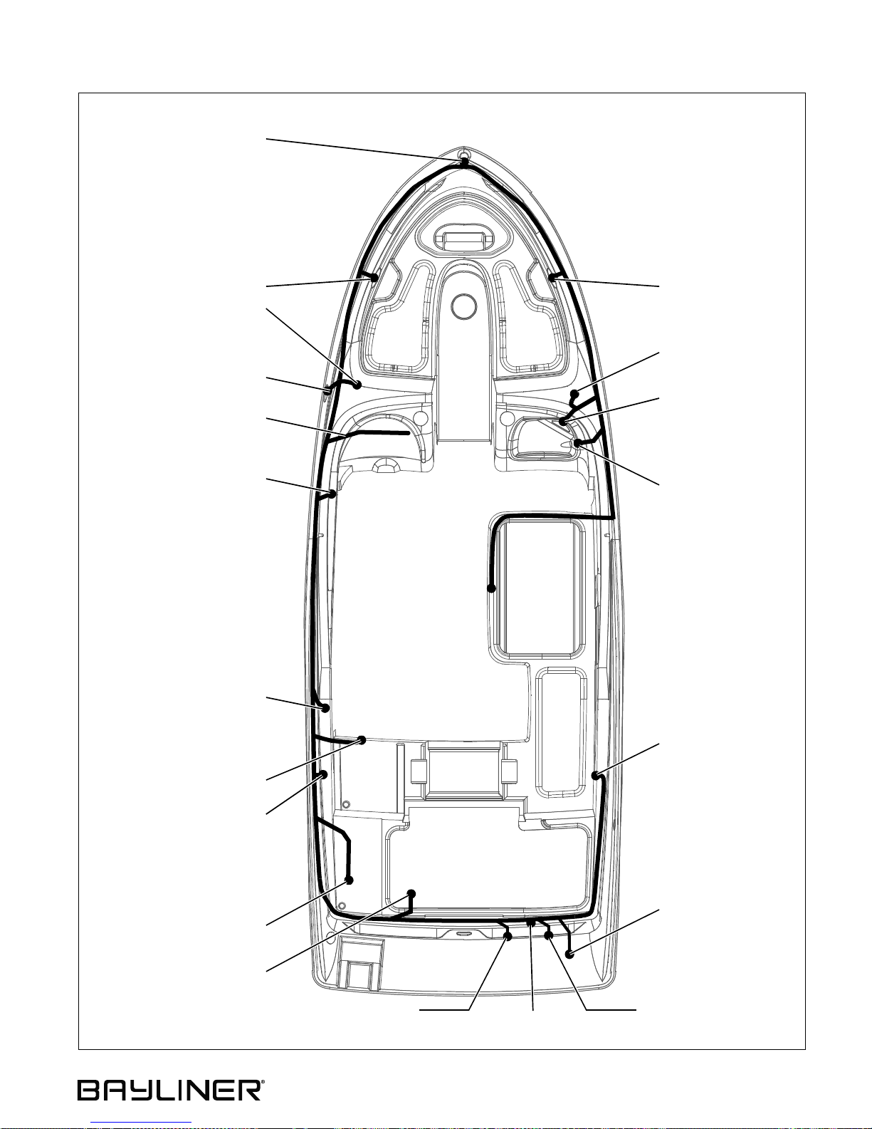
185, 205 & 225 • Owner’s Manual Supplement Chapter 11: Electrical System
225 Deck Electrical Ha rness
NOTE: VIEW IS UNDERSIDE OF DECK
BOW LIGHT
SPEAKER SPEAKER
FUSE BLOCK
CD CHANGER
(IF EQUIPPED)
HORN
CD STEREO
DASH HARNESS
SHIFTER
12 VOLT OUTLET &
WATER PUMP SWITCH
COURTESY LIGHT
SPEAKER
12 VOLT OUTLET
SPEAKER
WATER PUMP
ENGINE PLUG
ALL AROUND LIGHT
(REMOVEABLE)
BATTERY
TRIM PUMPBLOWER MOTOR
41
Page 48
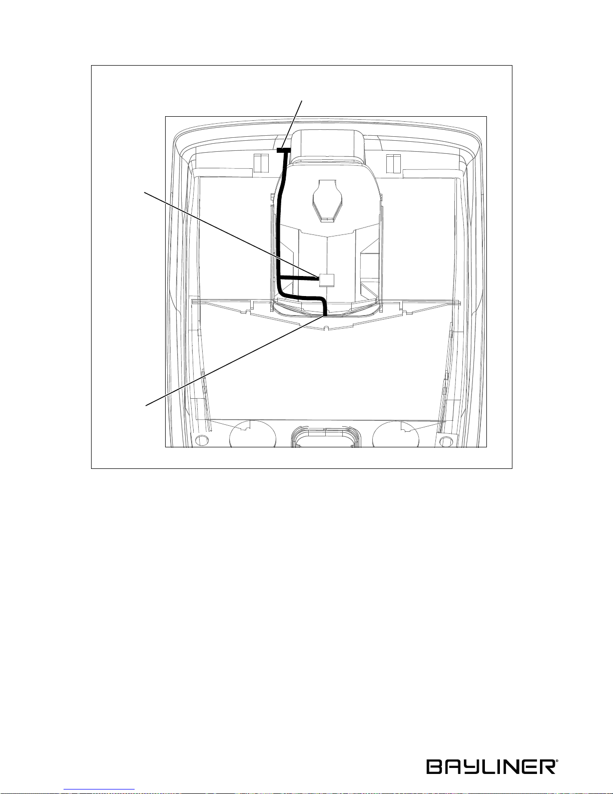
Chapter 11: Electrical System 185, 205 & 225 • Owner’s Manual Supplement
Hull Electrical Harnes s
NOTE: VIEW IS UNDERSIDE OF DECK
ENGINE PLUG
BILGE PUMP
FUEL TANK
SENDER
42
Page 49
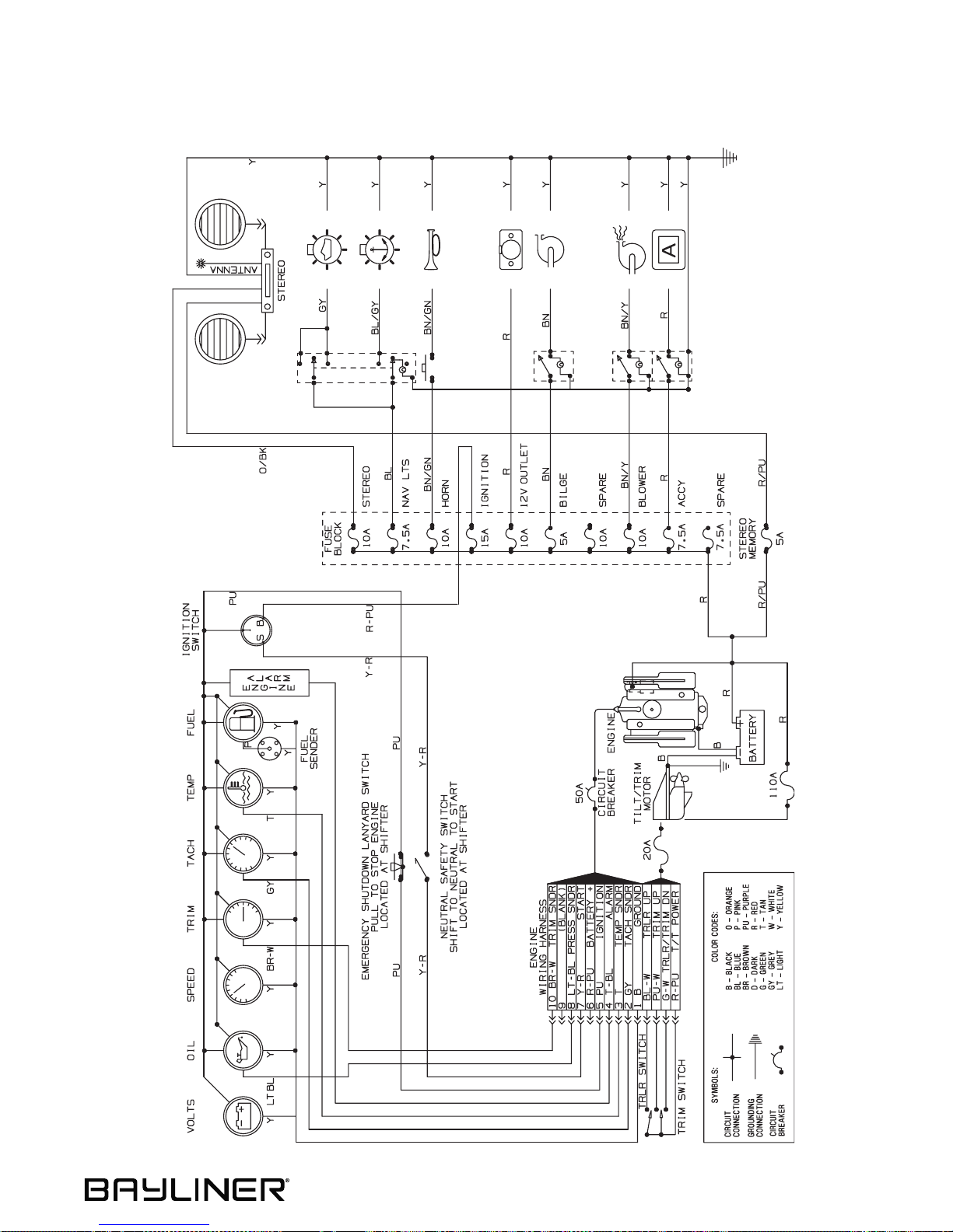
185, 205 & 225 • Owner’s Manual Supplement Chapter 11: Electrical System
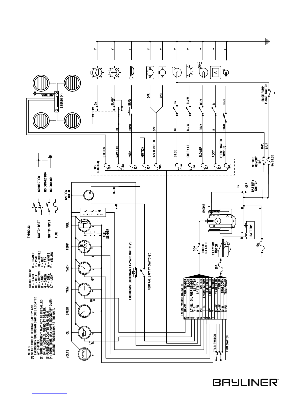
Wiring Diagrams
185 & 205
43
Page 50
Chapter 11: Electrical System 185, 205 & 225 • Owner’s Manual Supplement
225
44
Page 51
185, 205 & 225 • Owner’s Manual Supplement
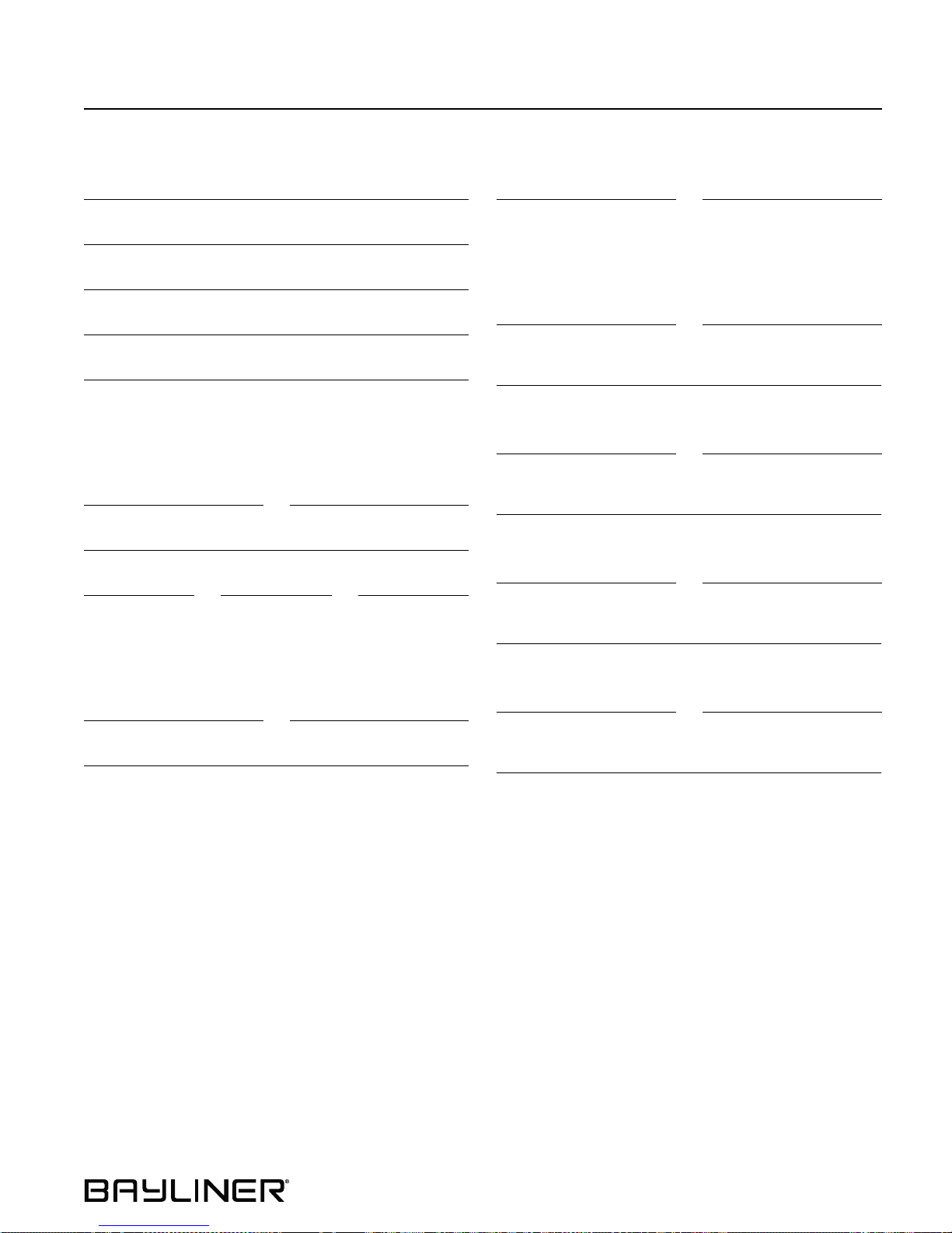
Important Records
Selling Dealer
Name Of Dealership
Address
Phone/FAX/E-mail
Sales Manager
Service Manager
Engine
Manufacturer Model Name/Number
Engine Serial Number
Oil Type/SAE Quarts per Engine Filter Type
Key Numbers
Ignition Other
Electronics
Manufacturer Model Name/Number
Serial Number
Manufacturer Model Name/Number
Serial Number
Manufacturer Model Name/Number
Propeller
Manufacturer Pitch
Model Number
Serial Number
Manufacturer Model Name/Number
Serial Number
45
Page 52
185, 205 & 225 • Owner’s Manual Supplement
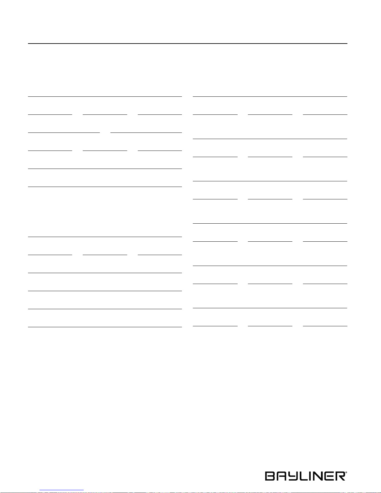
Float Plan
Before going boating, fill out a copy of this float plan (or similar) and leave it with a reliable person whom you can
depend on to contact the Coast Guard or other rescue organization, if you do not return as scheduled.
Description of Boat
Registration/Documentation Number
Length Make Type
Hull Color Trim Color
Fuel Capacity Engine Type Number of Engines
Distinguishing Features
Distinguishing Features
Operator of Boat
Full Name
Male or Female Age Health
Persons on Board
Full Name
Age Health Phone Number
Full Name
Age Health Phone Number
Full Name
Age Health Phone Number
Full Name
Age Health Phone Number
Address
Address
Phone/FAX/E-mail
Operator’s Experience
Full Name
Age Health Phone Number
Full Name
Age Health Phone Number
46
Page 53
185, 205 & 225 • Owner’s Manual Supplement Float Plan
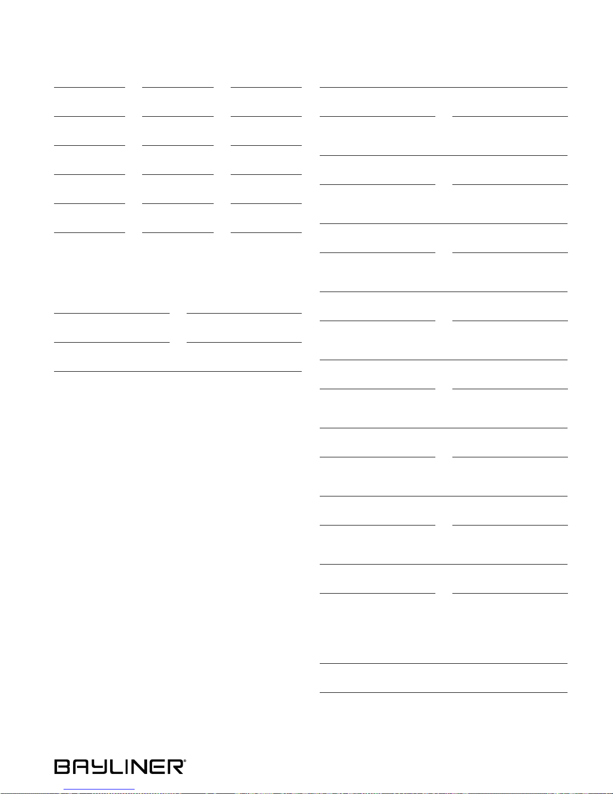
Survival Equipment
Marine Radio (Yes/No) Type Frequencies
Number of PFDs Flares (Yes/No) Mirror (yes or no)
Smoke Signals (Yes/No) Flashlight (Yes/No) Food (Yes/No)
Water (Yes/No) Anchor (Yes/No) Raft/Dinghy (Yes/No)
Paddles (Yes/No) EPIRB (Yes/No) Other
Other Other Other
Vehicle Description
Make Model
Color License Number
Trip Expectations
Departing From
Departure Date Departure Time
Stopover 1
Arrive No Later Than: Date Arrive No Later Than: Time
Stopover 2
Arrive No Later Than: Date Arrive No Later Than: Time
Stopover 3
Arrive No Later Than: Date Arrive No Later Than: Time
Where is the Vehicle Parked?
Stopover 4
Arrive No Later Than: Date Arrive No Later Than: Time
Stopover 5
Arrive No Later Than: Date Arrive No Later Than: Time
Stopover 6
Arrive No Later Than: Date Arrive No Later Than: Time
Final Destination Port (If Different Than Home Port)
Arrive No Later Than: Date Arrive No Later Than: Time
If not returned by the date and time list ed abov e, call
the Coast Guard or other local authority.
Coast Guard Phone Number
Local Authority Phone Number
47
Page 54

Owner’s Notes
Page 55

Page 56

Bayliner • P.O. Box 9029 • Everett, WA 98206 • 360-435-5571
Part Number 1757235
 Loading...