

Bay Linear, Inc
2418 Armstrong Street, Livermore, CA 94550 Tel: (925) 606-5950, Fax: (925) 940-9556 www.baylinear.com
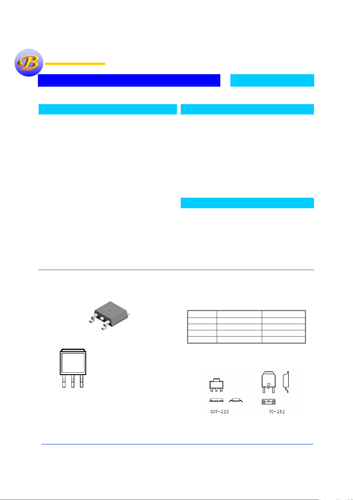
3-Terminal 1.5Amp Adjustable Voltage Regulator
LM317
Packaging Information
Ordering Information
Device Package Type Output
LM317T TO-220 1.5 Amp
LM317N SOT-223 1.0 Amp
LM317S TO-263 1.5 Amp
LM317D TO-252 1.5 Amp
SOT-223 Vs. TO-252 Package
Description
The Bay Linear LM317 are monolithic integrated circuit in
TO- 220, TO-252, SOT-223 and D2PAK packages intended
for use as positive adjustable voltage regulators.
They are designed to supply more than 1.5A of load current
with an output voltage adjustable over a 1.2 to 37V range.
The nominal output voltage is selected by means of only a
resistive divider, making the device exceptionally easy to use
and eliminating the stocking of many fixed regulators.
Features
• Output Current of 1.5A
• Output Voltage Tolerance of 5%
• Adjustable Output 1.2V to 37V
• 0.1% Load & Line Regulation
• Internal Short-Circuit Limited
• Current Limit
• Offer in plastic TO-252, TO-220, SOT-223
& TO-263
• Direct Replacement for LM317
Applications
• Post regulator for switching DC/DC
converter
• Bias supply for analog circuits
Bay Linear
Inspire the Linear Power
Top View
TO-263-3 (
1
Bay Linear
2
3
Top View
TO-263-3 (S)
1
Bay Linear
2
3
Top View
TO-263-3 (
1
Bay Linear
2
3
Top View
TO-263-3 (S)
1
Bay Linear
2
3
1. ADJ
2. Output
3. Input
Bay Linear, Inc
2418 Armstrong Street, Livermore, CA 94550 Tel: (925) 606-5950, Fax: (925) 940-9556 www.baylinear.com
LM317
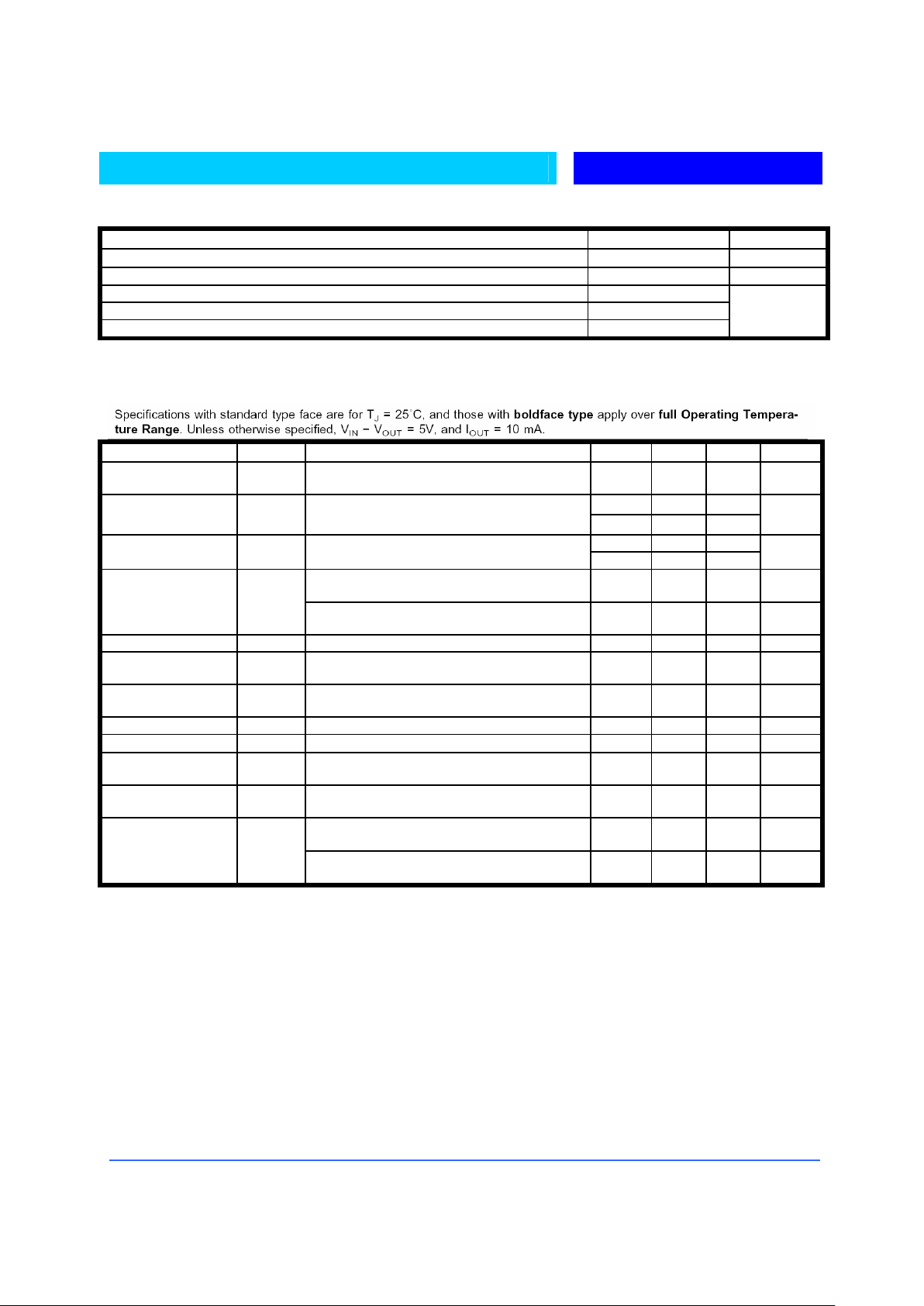
Absolute Maximum Rating
Parameter LM317 Unit
Power Dissipation Internally Limited
Input Voltage Differential +40V, -0.3V V
Operating Free-Air, Case, Virtual Junction Temp. 0 to 150
Storage Temperature Range -65 to 150
Lead temperature 1.6 mm from case for sec. 260
°C
Electrical Characteristics (LM317)
Parameter Symbol Conditions MIN TYP MAX UNIT
Reference Voltage V
O
3V≤(VIN-V
OUT
) ≤40V
10mA≤I
OUT≤IMAX
, P≤P
MAX
1.20 1.25 1.30 V
0.01 0.02 Line Regulation
∆V
O
3V≤(VIN-V
OUT
) ≤40V (Note 4)
0.02 0.05
%/V
0.1 0.3 Load Regulation
∆V
O
10mA≤I
OUT
≤I
MAX
(Note 4)
0.3 1
%
%
VI = 10V,, f=120Hz
C
ADJ
=0µF
65 dB
Ripple Rejection RR
V
I
= 10V,, f=120Hz
C
ADJ
=10µF
66 80 dB
Thermal Regulation
20ms 0.03 0.07 %W
Adjustment Pin
Current
50 100 µA
Adjustment Pin
Current Change
10mA≤I
OUT≤IMAX
,
3V≤(V
IN-VOUT
) ≤40V
0.2 5 µA
Temperature Stability T
MIN≤TJ≤TMAX
1 %
Long Term Stability
T
J
=125°C, 1000 hrs
0.3 1 %
RMS Output Noise %
of V
OUT
10Hz≤f≤10KHz 0.003 %
Minimum Load
Current
(VIN-V
OUT
) =40V 3.5 5 mA
(VIN-V
OUT
) ≤15V
P
D≤PMAX
1.5 2.2 A Maximum Load
Current
(V
IN-VOUT
) ≤40V
P
D≤PMAX
0.4 A

Bay Linear, Inc
2418 Armstrong Street, Livermore, CA 94550 Tel: (925) 606-5950, Fax: (925) 940-9556 www.baylinear.com
LM317
Application Notes:
The LM317 provides an internal reference
voltage of 1.25V between the output and
adjustments terminals. This is used to set a
constant current flow across an external resistor
divider show below, giving an output voltage
VO of:
V
O
= V
REF
( 1 + R 2 R 1 ) + IADJ R2
The device was designed to minimize the term
I
ADJ
( 100 m A max) and to maintain it very
constant with line and load changes. Usually,
the error term I
ADJ
V R2 can be neglected. To
obtain the previous requirement, all the
regulator quiescent current is returned to the
output terminal, imposing a minimum load
current condition. If the load is insufficient, the
output voltage will rise. Since the LM317 is a
floating regulator and ” sees” only the input- tooutput differential voltage, supplies of very high
voltage with respect to ground can be regulated
as long as the maximum input- to- output
differential is not exceeded. Furthermore,
programmable regulator are easily obtainable
and, by connecting a fixed resistor between the
adjustment and output, the device can be used as
a precision current regulator. In order to
optimise the load regulation, the current set
resistor R1 show below should be tied as close
as possible to the regulator, while the ground
terminal of R2 should be near the ground of the
load to provide remote ground sensing.
Performance may be improved with added
capacitance as follow:
An input bypass capacitor of 0.1µF
An adjustment terminal to ground 10µF
capacitor
to improve the ripple rejection of about 15 dB (
C
ADJ
).
An 1µF tantalium ( or 25 µFAluminium
electrolitic) capacitor on the output to improve
transient response. In additional to external
capacitors, it is good practice to add protection
diodes, as shown in below.
D1 protect the device against input short circuit,
while D2 protect against output short circuit for
capacitance discharging.

Bay Linear, Inc
2418 Armstrong Street, Livermore, CA 94550 Tel: (925) 606-5950, Fax: (925) 940-9556 www.baylinear.com
Advance Information- These data sheets contain descriptions of products that are in development. The specifications are based on the engineering calculations,
computer simulations and/ or initial prototype evaluation.
Preliminary Information- These data sheets contain minimum and maximum specifications that are based on the initial device characterizations. These limits are
subject to change upon the completion of the full characterization over the specified temperature and supply voltage ranges.
The application circuit examples are only to explain the representative applications of the devices and are not intended to guarantee any circuit
design or permit any industrial property right to other rights to execute. Bay Linear takes no responsibility for any problems related to any
industrial property right resulting from the use of the contents shown in the data book. Typical parameters can and do vary in different
applications. Customer’s technical experts must validate all operating parameters including “ Typical” for each customer application.
LIFE SUPPORT AND NUCLEAR POLICY
Bay Linear products are not authorized for and should not be used within life support systems which are intended for surgical
implants into the body to support or sustain life, in aircraft, space equipment, submarine, or nuclear facility applications without
the specific written consent of Bay Linear President.
 Loading...