

Page 1
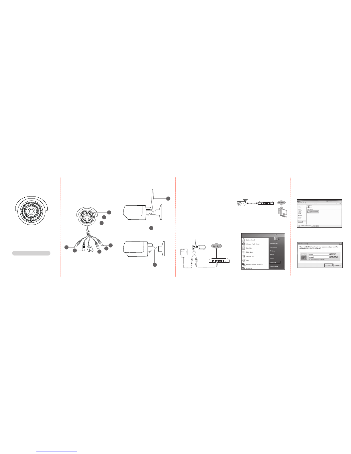
1. IR LED
2. Lens
3. Light Sensor
4. Audio out (Line out)
5. DC12V-IN Socket
6. Network port / PoE (Optional)
7. RESET Button (Optional)
8. Microphone in
1. Package Contents
Camera / DC Power Adapter /Antenna(B80) /
Mounting Screws / Quick installation Guide
2. Physical Descriptions
Bullet
IP Camera
(B80 Series)
3. Network Requirements
- An ADSL modem with Internet connection.
- A broadband router, preferably with Wi-Fi
capability. Please make sure DHCP is
enabled on your router.
- Android or iOS Smart Phone; 3G/Wi-Fi
network connection preferred.
- Laptop or Desktop
( OS : Windows 7 or above)
4. Device installation
A : Connect Camera to Internet setting.
a. Connect a network cable to the network
port and a LAN port of the router.
b. Then plug the power adapter of Camera
to power on the camera.
B. Power over Ethernet (PoE) for B80P model
a. Use a standard RJ-45 network cable and
connect the IP Camera to a PoE-enabled hub/
switch/router.
5. Live view via I.E Browser
Viewing Camera web page via Local network
(I.E Browser)
- B80
- B80
- B80P
Front View
Side View
9. Antenna
10. Bracket
b. Click network, then double click B80
(00:50:C2:F5:xx:xx)(xxx.xxx.xxx.xxx), Windows
will automatically open the browser
(please select IE browser)
c. Enter your Username and Password to log-in
to the IP camera. (Default is admin / 888888)
Quick Installation Guide
a. Click Computer
9
1
2
3
10
11. Bracket
11
4
5
6
7
8
12VDC Power
Ethernet Cable
ADSL Router
Hub / Switch / Router supporting PoE
Page 2
P/N: 2IG0B80X0111
7. Frequently Asked Questions
a. How to move your Camera to a new
environment:
- Wired mode: Remove the power adapter of
Camera & follow the Step 4.
b. If you are still having diculty, you may
attempt to perform a factory reset on your
Camera. Please go to the web page, and click
the “system maintenance” on the left. Then
nd out the “Reset to factory default” column
and click the “Default” to reset your Camera.
9. Install the Hardware
Wall mounting and Celling mounting
a. Attached the alignment sticker to the wall. Drill three
holes into the wall. Then hammer the supplied plastic
anchors into the screw holes and secure the bracket
with supplied screws.
b. Adjust the angle of the bracket to aim the desired area.
d. Click “Live view” to see the Live Video Image.
Note:
Please agree and install the Plug-in software
which showing from the IE browser when using
the camera at the rst time.
b. Add Camera
(i) Open “P2PCamLive” and “Click here to
add camera”, by scanning QR code on
the side of Camera to get the UID
(Unique ID) or you can enter it manually.
(ii) Enter Security Code (default: 888888)
then press OK to add your Camera.
(iii) Once you have seen the status of your
Camera is Online and then you can click
and watch the live video right away.
6. IP Camera Connection via P2P
a: Download APP “P2PCamLive” from Google
Play / Apple Store or scan QR code to install it.
AndroidiOS
c. Camera can support up to 32GB (FAT32) Micro
SD Card for recording storage.
d. If still cannot get the Live Video Image via IE
browser. How can I do?
Please remove Plug-in le then download and
install it again.
Wall Mounting Type
Celling Mounting Type
8. FCC Compliance and Advisory Statement
This equipment has been tested and found to comply with
the limits for a Class B digital device, pursuant to part 15 of the
FCC rules. These limits are designed to provide reasonable
protection against harmful interference in a residential
installation. This equipment generates, uses and can radiate
radio frequency energy and, if not installed and used in
accordance with the instructions, may cause harmful interference to radio communications. However, there is no guarantee that interference will not occur in a particular installation.
If this equipment does cause harmful interference to radio or
television reception, which can be determined by turning the
equipment o and on, the user is encouraged to try to correct
the interference by one or more of the following measures:
- Reorient or relocate the receiving antenna.
- Increase the separation between the equipment and
receiver.
- Connect the equipment into an outlet on a circuit
dierent from that to which the receiver is connected.
- Consult the dealer or an experienced radion/TV
technician for help.
Any changes or modications not expressly approved by the
party responsible for compliance could void the user's
authority to operate this equipment.
FCC RF Radiation Exposure Statement:
1. This Transmitter must not be co‐located or operating in
conjunction with any other antenna or transmitter.
2. This equipment complies with FCC RF radiation exposure
limits set forth for an uncontrolled environment. This
equipment should be installed and operated with a
minimum distance of 20 centimeters between the
radiator and your body.
 Loading...