

Page 1

4. Hydraulic Theory
TABLE OF CONTENTS
4. HYDRAULIC THEORY ..................................................3
4.1 Overview............................................................ 3
4.2 Dialysate Circuit................................................ 4
4.2.1 Incoming Water Pressure Regulator ............4
4.2.2 Water On/Off Valve.....................................5
4.2.3 Heat Exchanger............................................5
4.2.4 Heater, Thermistor, Safety Thermostat........5
4.2.5 Concentrate Line Regulator(s) and
Concentrate Central Delivery Systems
(optional)...................................................6
4.2.6 Volumetric Proportioning System ...............6
4.2.7 Supply Manifold ..........................................6
4.2.8 Air Removal System ....................................9
4.2.9 "A" & "B" Rinse Fittings .............................9
4.2.10 Supply Pump Recirculation Loop..............9
4.2.11 Input Pressure Equalizer, Flow Equalizer,
and Output Pressure Equalizer................12
4.2.12 End-of-Stroke Sensors .............................12
4.2.13 Dialysate Monitoring Manifold ................14
4.2.14 Dialysate Bypass Valve and Sensor.........16
4.2.15 Rinse Block..............................................17
4.2.16 Dialysate Sample Ports .............................17
4.3 Ultrafiltration System ..................................... 17
4.4 Blood Leak Detector....................................... 18
4.5 Other Components ......................................... 18
4.5.1 Rinse Valve................................................18
4.5.2 Heat Disinfection Recirculation Valve ......19
4.5.3 Citric Acid Valve Manifold (optional) ......19
Standard Hydraulics Flow Diagram ..................... 21
157-1278-893 Rev A 4-1
January 2004
Page 2

Arena Service Manual
4-2 157-1278-893 Rev A
January 2004
Page 3
4. HYDRAULIC THEORY
4.1 OVERVIEW
The Arena Instrument is designed to heat incoming water to
approximately human body temperature, mix the water with
dialysate concentrate in physiologically correct proportions and
infuse the dialysate through an artificial kidney to effect
hemodialysis therapy. In doing this, it also accurately measures
the amount of fluid entering and exiting the artificial kidney and
can adjust these volumes to control the fluid removal from the
patient. Operation of the hydraulic components is controlled by
several microprocessors. Refer to Figures 4-1 and 4-2 for the
location of components in the Instrument and to the standard
hydraulics diagram (157-1278-587) at the end of this section for
thier sequence in the flow path.
4. Hydraulic Theory
Figure 4-1. Standard Hydraulics Module, Front View
157-1278-893 4-3
January 2004
Page 4
Arena Service Manual
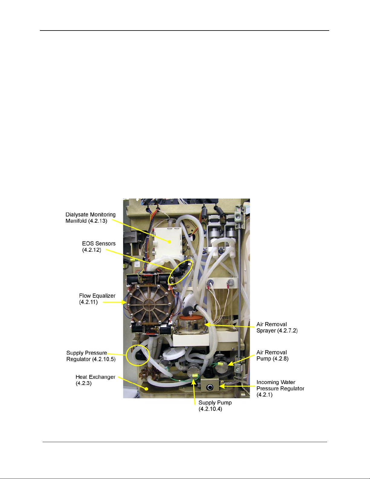
Figure 4-2. Standard Hydraulics Module, Rear View
4.2 DIALYSATE CIRCUIT
4.2.1 Incoming Water Pressure Regulator
The pressure of the incoming water is reduced and stabilized by
the adjustable water pressure regulator to the factoryrecommended level (see Section 18, Calibration Procedures).
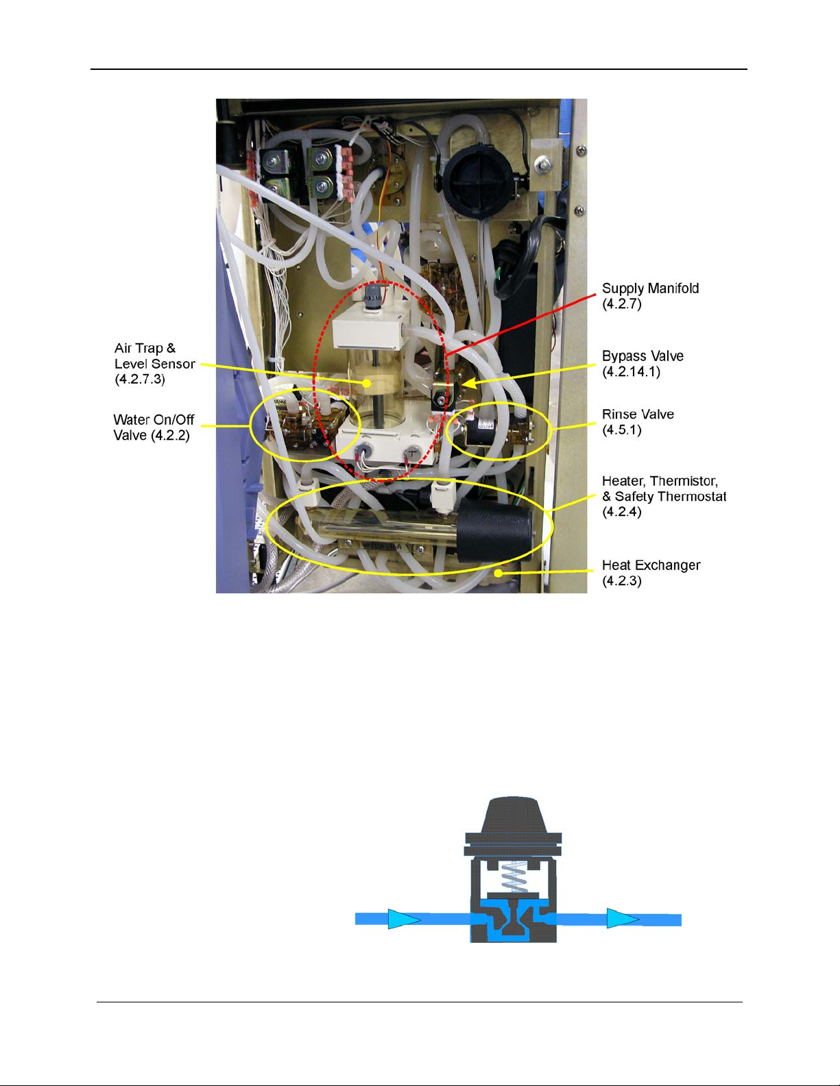
Figure 4-3. Incoming Water Pressure Regulator
4-4 157-1278-893 Rev A
January 2004
Page 5
4. Hydraulic Theory
4.2.2 Water On/Off Valve
This valve is actuated through a coil using unregulated +24 VDC.
When the power is off, the valve is closed preventing water from
entering the Instrument. When power is on, the on/off valve
operation is controlled by the supply manifold level sensor signal.
During heat cleaning, the valve is closed. This valve can be
monitored using the DS1 “Flow Control” LED on the I/O
Hydraulics Power board (see Section 5, Electronic Theory).
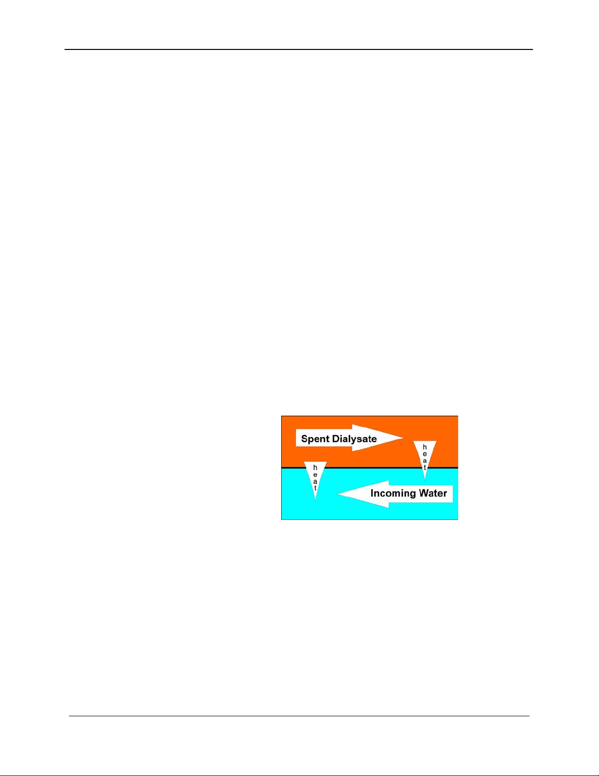
4.2.3 Heat Exchanger
Incoming water flows through a hydraulic channel on one side of a
stainless steel plate. On the other side of the plate, the spent
dialysate flows in a countercurrent direction in an identical
hydraulic channel before draining out of the Instrument.
Heat is transferred from the spent dialysate to the incoming water
through the plate. This heat transfer preheats the incoming water,
shortening dialysate warm up time. By reducing the time the
heater is on, the heat exchanger saves energy.
The heat exchanger allows the Instrument to be used with a wider
range of incoming water temperatures since this preheating of the
incoming water reduces these variations.
Figure 4-4. Heat Exchanger
4.2.4 Heater, Thermistor, Safety Thermostat
The water is heated to the desired temperature by a heater. On the
output of the heater is a thermistor. The thermistor resistance
changes in inverse proportion to temperature changes. The
thermistor sends a signal to the UF-Proportioning Power board,
which then turns the heater on or off to maintain or increase the
temperature.
Next to the heater is a resettable thermostat, which prevents the
heater from exceeding a temperature of approximately 107°C
157-1278-893 4-5
January 2004
Page 6

Arena Service Manual
4.2.5 Concentrate Line Regulator(s) and Concentrate
4.2.6 Volumetric Proportioning System
(225°F). The thermostat turns off power to the heater to prevent
damage in case of a runaway temperature circuit failure.
For testing purposes, the heater has a resistance of approximately
10-20 Ω when cold. The thermistor has a resistance of
approximately 3 KΩ at 37 to 38°C and 5 KΩ at 25°C.
Central Delivery Systems (optional)
Concentrate Line Regulators are recommended when a central
delivery system is used to feed concentrates into the Instrument.
Refer to Section 7, Dialysate Preparation, for more information.
The Instrument's volumetric proportioning system consists of fixed
volume pumps for concentrates and a fixed volume metering
device (Flow Equalizer) for dialysate. They are linked
electronically through the Ultrafiltration Controller to provide a
fixed ratio proportioning system.
Refer to Section 7, Dialysate Preparation, and Section 8,
Ultrafiltration, for more information.
4.2.7 Supply Manifold
The supply manifold controls the incoming water flow, mixes the
“A” dialysate concentrate component, removes the dissolved air
from the water, and monitors the “A” concentrate and water
conductivity. The supply manifold is composed of four
components:
• “A” Mix Chamber and Air Gap
• Air Removal Sprayer
• Air Trap and Level Sensor
• “A” Conductivity Probe/Thermistor Set
This manifold also contains the connections for the air removal
pump, and the “A” and “B” rinse fittings that connect through a
common line to the supply manifold and draw rinse water from
this source.
The “A” concentrate pump is described in Section 7, Dialysate
Preparation.
4-6 157-1278-893 Rev A
January 2004
Page 7

4. Hydraulic Theory
Figure 4-5. Supply Manifold
4.2.7.1 “A” Mix Chamber and Air Gap
As the name implies, the “A” mix chamber mixes the water and
“A” concentrate into a uniform solution.
The air gap at the top of this chamber is at atmospheric pressure,
which helps to limit proportioning errors. The air gap also acts as
a barrier preventing back flow in the event of a drop in the
incoming water pressure.
4.2.7.2 Air Removal Sprayer
The sprayer is part of the air removal system. Refer to Section 7,
Dialysate Preparation, for more information.
4.2.7.3 Air Trap and Level Sensor
The air trap and level sensor control the flow of water into the
hydraulic system by causing the water on/off valve to open when
the level drops and by closing the valve when the level rises.
The level sensor consists of a float with magnet and a Hall-effect
switch. When the water level float magnet is below the sensor, the
condition indicates the need for more water, opening the incoming
157-1278-893 4-7
January 2004
Page 8

Arena Service Manual
water on/off valve. When the magnet is above the sensor, the
condition indicates the air trap is full, closing the incoming water
on/off valve.
In normal operation, as the supply pump draws solution from the
air trap chamber to fill the flow equalizer, the liquid level in the
chamber is lowered along with the float causing the water on/off
valve to open so water again fills the chamber.
When the air trap level rises, the level sensor signal shuts off the
water on/off valve. This cycle is repeated during every fill phase
of the flow equalizer.
4.2.7.4 "A" Conductivity Probe/Thermistor Set
This is one of three conductivity probe sets. The other two are
described in Section 4.2.10.3, "B" Conductivity Probe/Thermistor
Set, and Section 4.2.13.1, Dialysate (Primary) Conductivity
Probe/Thermistor Set.
Figure 4-6. "A" Probe/Thermistor Set
Conductivity is used as a measure of the electrolyte composition of
dialysate. The hardware for measuring conductivity is always a
cell for measuring changing resistance as the amount of dissolved
salt changes and a thermistor for measuring temperature changes.
Electronic circuits are used to equate these changing resistances to
the standard measuring conditions of a 1 cm cell at 25 Celsius.
The information from these devices can be used to give us
conductivity in the units of milliSiemens/cm (mS/cm) @ 25°C.
The “A” conductivity thermistor is not used to control or monitor
the temperature of the dialysate. It is calibrated with the other
thermistors during temperature calibration.
4-8 157-1278-893 Rev A
January 2004
Page 9

4. Hydraulic Theory
4.2.8 Air Removal System
The air removal system removes dissolved gases that are trapped
in the water used to make up dialysate. The air removal system
consists of the air removal sprayer, the air removal pump, and the
vented air trap.
The air removal sprayer nozzle restricts the flow so that a partial
vacuum of approximately 500 to 650 mmHg is created in the air
removal sprayer chamber. The fluid that passes through the air
removal sprayer is deflected into a conical spray pattern. By
developing a spray pattern, a larger surface area is exposed to the
500 to 650 mmHg vacuum. The vacuum pulls the air out of the
solution. Due to the large surface area of fluid exposed to the
vacuum, the rate at which the air comes out of the water is
increased, enhancing the air removal function.
The air removal pump (also known as the deaeration pump) runs at
a constant speed of approximately 1500 mL/min for all flow rates,
pulling the solution through the air removal sprayer nozzle.
The vented air trap provides an opening for air to leave the system.
For more information, refer to Section 4.2.7 and Section 7,
Dialysate Preparation.
4.2.9 "A" & "B" Rinse Fittings
The “A” and “B” rinse fittings are located on the right side panel
of the Instrument. Both fittings are connected to a source of water
in the supply manifold. This water is used to rinse the concentrate
lines and concentrate pumps.
A proximity sensor built into each of the rinse fittings senses when
the concentrate lines are attached. The rinse fittings are keyed so
that the “A” concentrate line will not fit into the “B” concentrate
fitting and vice versa. When the “B” concentrate line is not in use
during acetate dialysis or during rinse, it is connected to its rinse
fitting.
4.2.10 Supply Pump Recirculation Loop
The supply pump recirculation loop mixes the “B” concentrate,
monitors the total conductivity, regulates the pressure, and pumps
dialysate to the flow equalizer. This loop contains the inlet for the
“B” concentrate pump, the "B" (bicarbonate) mix chamber, the
157-1278-893 4-9
January 2004
Page 10

Arena Service Manual
“B” conductivity probe, the supply pressure pump, and the supply
pressure regulator. Figure 4-7 describes this loop.
The loop configuration helps to mix the bicarbonate concentrate by
recirculating the solution through the “B” mix chamber. The loop
also acts as a conduit for flow that is diverted by the supply
pressure regulator at the end of each flow equalizer fill cycle.
Figure 4-7. Supply Pump Recirculation Loop
4.2.10.1 "B" Mix Point
Bicarbonate concentrate enters the water-acid concentrate mixture
at the “B” mix point.
4.2.10.2 "B" Mix Chamber
During hemodialysis therapy, the solution that enters the “B” mix
chamber from the supply manifold contains water and acetate
concentrate, or water and the acid and bicarbonate components of
bicarbonate dialysate (depending on the concentrates selected).
This chamber mixes the solution before it is monitored by the “B”
conductivity probe.
4.2.10.3 "B" Conductivity Probe/Thermistor Set
This is one of three conductivity probe sets. The other two are
described in Section 4.2.7.4, "A" Conductivity Probe/Thermistor
Set, and Section 4.2.13.1, Dialysate (Primary) Conductivity
Probe/Thermistor Set.
4-10 157-1278-893 Rev A
January 2004
Page 11

4. Hydraulic Theory
Figure 4-8. "B" Probe/Thermister Set
The second conductivity probe in the flow path is located at the
outlet of the “B” mix chamber in the dialysate supply recirculation
loop. The probe/thermistor set is identical to the “A” conductivity
probe/thermistor set. In addition to compensating for temperature
effect on the conductivity reading, the “B” thermistor is also the
source of the temperature reading for the redundant high
temperature alarm as well as fine-tuning the dialysate temperature
control. Refer to Section 6, Temperature Control, for more
information on temperature control.
The “B” probe monitors the total conductivity of the dialysate
solution after both concentrates are mixed. The UF-Proportioning
Controller board subtracts the “A” conductivity probe reading
from the “B” conductivity probe reading and compares the
difference to the expected result. In the acetate therapy mode, the
result of this calculation should be zero and is used to recheck the
“A” conductivity probe reading. When bicarbonate dialysate is
used, the UF-Proportioning Controller board calculates whether
the conductivity contribution of the “B” portion of the solution is
acceptable for the type of bicarbonate concentrate used.
4.2.10.4 Supply Pump
The supply pump fills the flow equalizer with fluid. The supply
pump pumps at a rate slightly higher than the dialysate flow rate
set by the operator. This extra flow ensures an adequate supply of
solution to fill the flow equalizer. For more information on the
speed control of the supply pump, refer to Section 7, Dialysate
Preparation.
157-1278-893 4-11
January 2004
Page 12

Arena Service Manual
4.2.11 Input Pressure Equalizer, Flow Equalizer, and
4.2.12 End-of-Stroke Sensors
4.2.10.5 Supply Pressure Regulator
The supply pressure regulator controls the peak input pressure to
the "pre" side of the input pressure equalizer. When the flow
equalizer cavity is filled, the pressure in the pressure regulator
increases to its maximum value (16 psi ±1), overcoming the spring
force of the regulator spring allowing the dialysate to recirculate
back to the “B” mix chamber. The Supply Pressure Regulator is
equivalent to an adjustable pressure relief valve. See also Section
8, Ultrafiltration.
Output Pressure Equalizer
Refer to Section 8, Ultrafiltration, for a detailed description of
these components.
The end-of-stroke (EOS) sensors are infrared optical devices
located in the flow path after the Flow Equalizer and before the
Output Pressure Equalizer. These sensors verify when the Flow
Equalizer compartments have reached the end of the fill cycle.
When the compartments are full, the sensor sends a signal to the
UF-Proportioning Power board. The EOS sensors are used to
minimize the end-of-stroke time of the Flow Equalizer by
controlling the flow rate of the supply pump via feedback from the
sensors.
The Instruments that have temperature-dependent EOS sensors,
work with self-heating thermistors. The temperature of these
thermistors will rise when the flow through them stops.
The Instrument may have optical EOS sensors like the one shown
in Figure 4-9. (The diagrams in this section show the optical
sensor.) The main components are two small PCBs, one on each
side of the assembly, and one diaphragm right in the middle of the
assembly. One PCB has the circuitry for the LED, and the other
for the Detector. On the body of the assembly, the orientation of
the diaphragm is indicated by a raised alignment symbol.
4-12 157-1278-893 Rev A
January 2004
Page 13

4. Hydraulic Theory
Figure 4-9. Optical Sensor Assembly
The diaphragm has four flaps that will open under a pressure of 0.5
PSI, allowing the light from the LED to go across the assembly
and reach the Detector (see Figure 4-10). This will indicate that
dialysate is flowing. When the flow stops, the diaphragm will
close, blocking the light from the LED, which indicates that the
flow stopped.
A green LED on the Detector PCB will turn on when the Detector
does not get any light.
157-1278-893 4-13
January 2004
Page 14

Arena Service Manual
Figure 4-10. Optical/Diaphragm Sensors for EOS
4.2.13 Dialysate Monitoring Manifold
The purpose of this assembly is to house the components to
monitor the dialysate temperature, conductivity and pressure. This
manifold contains:
The dialysate (primary) conductivity probe/thermistor set
The dialysate pressure transducer
The bypass valve flow sensor
4-14 157-1278-893 Rev A
January 2004
Page 15

4. Hydraulic Theory
Figure 4-11. Dialysate Monitoring Manifold
4.2.13.1 Dialysate (Primary) Conductivity Probe/Thermistor
Set
This is one of three conductivity probe sets. The other two are
described in Section 4.2.7.4, "A" Conductivity Probe/Thermistor
Set, and Section 4.2.10.3, "B" Conductivity Probe/Thermistor Set.
Figure 4-12. "Primary" Probe /Thermistor Set
The third conductivity probe/thermistor set is located in the
Dialysate Monitoring Manifold at the outlet of the output pressure
157-1278-893 4-15
January 2004
Page 16

Arena Service Manual
4.2.14 Dialysate Bypass Valve and Sensor
equalizer. This probe set is identical to the other conductivity
probe sets. It measures the total conductivity of the dialysate
before it enters the artificial kidney. This temperaturecompensated conductivity value is displayed in the
CONDUCTIVITY window. The primary conductivity alarm
circuit also uses the signal from this probe.
As mentioned previously, a thermistor is built into one of the
electrodes. This thermistor supplies information for the
temperature display and the primary high and low temperature
alarm limits. For more information on temperature monitoring,
refer to Section 6, Temperature Control.
4.2.13.2 Dialysate Pressure Transducer
This pressure transducer senses the dialysate pressure and changes
the pressure reading into an analog electrical signal proportional to
pressure. This signal is used for the transmembrane pressure
display and alarms.
4.2.14.1 Bypass Valve
The bypass valve protects the patient in the event of a temperature
or conductivity alarm by diverting unacceptable dialysate away
from the dialyzer. The diverter is a +24 VDC three-way solenoid
valve, controlled by the I/O Hydraulics Power board. During a
dialysate temperature or conductivity alarm, an electronic signal
causes the bypass valve to close the fluid path leading to the
dialyzer and shunt the dialysate to the drain.
On the I/O Hydraulics Power Board, LED DS6 indicates Bypass
(off) or Flow (on). See Figure 4-13 for location.
Figure 4-13. Bypass/Flow LED
4-16 157-1278-893 Rev A
January 2004
Page 17

While in Rinse Mode, the Instrument will automatically go into
Bypass Mode periodically.
There is also a manual Bypass Mode that permits the operator to
put the Instrument in bypass when a dialyzer is connected or
sequential ultrafiltration therapy is performed. This manual
Bypass Mode is activated via the Bypass switch located on the
Membrane Switch Panel.
4.2.14.2 Bypass Valve Flow Sensor
A temperature-dependent flow sensor connected (see Figure 4-11)
to the dialysate monitoring manifold after the bypass valve is used
to monitor dialysate flow. When the Instrument is in bypass, the
bypass valve diverts the dialysate flow away from the dialyzer;
therefore this sensor verifies the correct functioning of the bypass
valve by detecting that no flow is going through the sensor. The
Instrument generates a shutdown alarm in the event of a bypass
valve failure.
The signal from the Flow Sensor is also used to indicate dialysate
flow or bypass on the touchscreen display. Refer to Section 4.2.12
for more information on the sensor assembly.
4. Hydraulic Theory
4.2.15 Rinse Block
When the Instrument is not being used for a patient treatment and a
dialyzer is not in use, the dialysate lines are attached to a rinse
block. The rinse block has proximity sensors that are used to
determine the placement of the dialyzer connectors and are used as
interlocks for mode changes.
4.2.16 Dialysate Sample Ports
The sample ports (pre- and postdialyzer) are provided as an
opening for the operator to obtain a sample of the dialysate to test
for conductivity or residual disinfectant.
4.3 ULTRAFILTRATION SYSTEM
The ultrafiltration (UF) system allows the operator to remove a
precise amount of fluid from a patient in a controlled manner. By
controlling exactly how much dialysate is going to and returning
from the dialyzer, accurate fluid removal is achieved.
The main components of the UF system are (as they appear in the
flow path):
Supply Pump
150µ Particle Filter
157-1278-893 4-17
January 2004
Page 18

Arena Service Manual
Supply Pressure Regulator
Input Pressure Equalizer
Flow Equalizer
Output Pressure Equalizer
Dialyzer Connectors and Dialyzer
Check Valve
Dialysate Pressure Pump
Flow Restrictor
UF Removal Regulator
UF Flow Meter
Refer to Section 8, Ultrafiltration Control, for more information on
the UF System.
4.4 BLOOD LEAK DETECTOR
Spent dialysate expelled from the flow equalizer passes through
and is monitored for the presence of blood in the blood leak
detector. There is a light source and a photocell which monitors
the light transmitted through the solution present in the cavity. If
blood leaks through the dialyzer membrane, the blood passing
through the blood leak detector will absorb a portion of the light,
preventing it from reaching the photocell. The dimmed light then
sets off a blood leak alarm and protects the patient by stopping the
blood pump, clamping the venous line, and warning the operator.
For more information, refer to Section 14, Blood Leak Detector.
4.5 OTHER COMPONENTS
4.5.1 Rinse Valve
The rinse valve (also called the dialysate pressure relief valve)
connects to the fluid path immediately after the flow sensor on the
downstream side of the dialyzer. When the Instrument is in the
Rinse Mode, the electronics control the UF flow meter to meter 3.6
L/h of fluid out of the flow path. Fluid must be added to the
system to prevent a vacuum from being built up in the flow path.
The rinse valve allows fluid from the drain line to replace the
volume removed by the UF flow meter.
4-18 157-1278-893 Rev A
January 2004
Page 19

4. Hydraulic Theory
The rinse valve is open in the Rinse and Prime Modes, in Self Test
(except UF test) and in the Calibration Mode when the UF Flow
Meter is being calibrated. Therefore, when the dialyzer connectors
are not connected to the Instrument, the rinse valve must be closed.
4.5.2 Heat Disinfection Recirculation Valve
The heat disinfection recirculation valve diverts the effluent water
back into the input side of the heater (with the water on/off closed)
in order to heat the water to above 84°C and maintain that fluid
path temperature for the time set by the service technician. For
more information, refer to Section 9, Disinfection.
4.5.3 Citric Acid Valve Manifold (optional)
This manifold is part of the Citric Acid option. It consists of a
normally-closed two-way valve, which opens during the Citric
Acid Heat Clean Mode if the dialyzer connectors are on the rinse
block and citric acid is to be infused.
If the dialyzer connectors are removed from the rinse block during
citric acid infusion, the citric acid valve will close, citric acid
infusion will stop, and the message PLACE DIALYZER LINE ON
RINSE BLOCK will be displayed.
For more information on the Citric Acid option, refer to Section 2,
Physical Description, and Section 9, Disinfection.
Figure 4-14. Citric Acid Option Hardware
157-1278-893 4-19
January 2004
Page 20

Arena Service Manual
4-20 157-1278-893 Rev A
January 2004
 Loading...