

Page 1
Page 2

Page 3
Page 4

Page 5
Page 6

Page 7
TABLE OF CONTENTS
CHAPTER I- INTRODUCTION
1.1
1.2 FACTORY SERVICE/ASSISTANCE
GENERAL ..............................................................................................................
................................................................... 1-I
...................................................................... l-l
1.2.1 Technical Assistance, Service, and Repairs
1.2.2 Customer Service Related Business.
1.2.3 Technical Assistance Hotline-
.............................................................................
CHAPTER 2 - THEORY OF OPERATION
2.1 OVERVlEW OFTHE AP II PUMP
2.2 AP II PUMP COMPONENTS
2.2.1 Microprocessor and PROM Subsystem
2.2.2
2.2.3
2.2.4
2.2.5
2.2.6
2.2.7
2.2.8
BUS Subsystem
Keypad Subsystem
Supervisory Subsystem (SS)
Power Subsystem (PS)
LCD Subsystem
Buzzer Circuit
Motor Subsystem
................................................................................................
...........................................................................................
................................................................................................
....................................................................................................
..............................................................................................
.................................................................................
............................................................................
.....................................................................................
.................................................................
.................................................... 2-I
.......................................................................... 2-l
............................................................
l-l
...................................................... 1-l
1-I
1-l
2-2
2-3
2-4
2-4
2-5
2-5
2-5
2-6
2-6
2.3
2.3.1
2.3.2
2.3.3
MISCELLANEOUS CIRCUITS
Occlusion Detection Circuits
Backlight Circuit
................................................................................................
Printer Adapter Interface Circuit.
..............................................................................
.............................................................................
CHAPTER 3 - INITIAL INSPECTION
3.1 GENERAL
3.2
3.3
INITIAL INSPECTlON AND DAMAGE CHECK
INSPECTIONS
..............................................................................................................
.......................................................................................................
CHAPTER 4 - FUNCTIONAL TESTS
4.1
4.1.1
4.1.2
4.2
GENERAL
Equipment Required
Optional Equipment
VISUAL INSPECTION
..............................................................................................................
.........................................................................................
...........................................................................................
...........................................................................................
.......................................................................
........................................................... 3-I
.....................................................
...........................................................
2-6
2-6
2-6
2-7
3-l
3-l
3-l
4-1
4-1
4-1
4-1
4-2
4.3
4.3.1
4.3.2
FLOW RATE ACCURACY TEST
Procedure using Gravimetric method
Procedure using
Volumetric method
...........................................................................
................................................................
.................................................................
4-3
4-3
4-4
Page 8
TABLE OF CONTENTS
4.4
4.4.1
4.4.2
4.4.3
4.4.4
4.4.5
4.4.6
4.5
CHAPTER 5 - ROUTINE MAINTENANCE
5.1
5.2
MISCELLANEOUS CHECKS ................................................................................
Tubing Sensor Test ...........................................................................................
Occlusion Switch Test .......................................................................................
PCA Cable Test .................................................................................................
AC Adapter Test ................................................................................................
History Retention Test .......................................................................................
Printer Test (Optional) .......................................................................................
FUNCTIONAL TEST DATA SHEET . . . ..~.............~.................................................
. . . . . . . . . . . . . . . . . . . . . . . . . . . . . . . . . . . . . . . . . . . . . . . . . . .
GENERAL . . . . . . . . . . . . . . . . . . . . . . . . . . . . . . . . . . . . . . . . . . . . . . . . . . . . . . . . . . . . . . . . . . . . . . . . . . . . . . . . . . . . . . . . . . . . . . . . . . . . . . . . . . . . . .
CLEANING AND DISINFECTING . . . . . . . . . . . . . . . . . . . . . . . . . . . . . . . . . . . . . . . . . . . . . . . . . . . . . . . . . . . . . . . . . . . . . . . . . .
CHAPTER 6 - TROUBLESHOOTING AND REPAIR
6.1
GENERAL . . . . . . . . . . . . . . . . . . . . . . . . . . . . . . . . . . . . . . . . . . . . . . . . . . . . . . . . . . . . . . . . . . . . . . . . . . . . . . . . . . . . . . . . . . . . . . . . . . . . . . . . . . . . . . 6-l
. . . . . . . . . . . . . . . . . . . . . . . . . . . . . . . . . . .
4-6
4-6
4-6
4-7
4-8
4-8
4-8
4-10
5-I
5-1
5-1
6-I
-
6.2
6.2.1
6.2.2
6.2.3
6.2.4
6.2.5
TROUBLESHOOTING ...........................................................................................
Board Exchange ................................................................................................
Mechanism Exchange .......................................................................................
Tools and Equipment .........................................................................................
Troubleshooting Tips .........................................................................................
System Error Codes (Failure Codes)
................................................................
6-l
6-1
6-1
6-2
6-2
6-5
CHAPTER 7 - DISASSEMBLY/ASSEMBLY PROCEDURES .................... ..7- 1
7.1
7.2
7.2.1
7.2.2
7.2.3
7.2.4
7.2.5
7.2.6
7.2.7
GENERAL .............................................................................................................. 7-1
DISASSEMBLY PROCEDURES ............................................................................
Reservoir Assembly ..........................................................................................
Rear Case Half Assembly .................................................................................
Mechanism Assembly and Battery Compartment Removal ..............................
MPU Circuit Board Assembly ............................................................................
3V Backup Battery Replacement ......................................................................
LCD Circuit Board Assembly .............................................................................
7-l
7-2
7-3
7-4
7-5
7-7
7-8
Keypad .............................................................................................................. 7-9
APPENDIX A - SCHEMATIC DIAGRAM . . . . . . . . . . . . . . . . . . . . ..*.............................. A-l
A.1 GENERAL . . . . . . . . . . . . . . . ..~............................................................................................ A-l
Page 9
TABLE OF CONTENTS
APPENDlX B - CIRCUIT BOARD ASSEMBLY
B.l GENERAL
APPENDIX C - REPAIR PARTS
C.l
C.2 ASSEMBLY PART USTINGS
c.2.1
c.2.2 Rear Case Half
C.2.3
C.2.4
C.2.5 LCD Circuit Board Assembly and Front Case Half Parts
C.3 ALPHABETICAL PARTS LIST
C.4 NUMERICAL PARTS UST
GENERAL
Reservoir Assembly .......................................................................................... c-2
Mechanism Assembly and Battery Compartment Parts
MPU Board Assembly Parts and ESD Shield
APPENDIX D - PRODUCT UPDATES
. . . . . . . . . . . . . . . . . . . . . . . . . . . . . . . . . . . . . . . . . . . . . . . . . . . . . . . . . . . . . . . . . . . . . . . . . . . . . . . . . . . . . . . . . . . . . . . . . . . . . . . . . . . . . .
. . . . . . . . . . . . . . . . . . . . . . . . . . . . . . . . . . . . . . . . . . . . . . . . . . . . . . . . . . . . . . . . . . C-1
. . . . . . . . . . . . . . . . . . . . . . . . . . . . . . . . . . . . . . . . . . . . . . . ..*..*.........................................................
................................................................................
.................................................................................................. c-3
. . . . . . . . . . . . . . . . . . . . . . . . . . . . . . . . . . . . . . . . . . . . . . . . . . . . . . . . . . . . . . . . . . . . . . . . . . . . . .
. . . . . . . . . . . . . . . . . . . . . . . . . . . . . . . . . . . . . . . . . ..~........................................ C-8
. . . . . . . . . . . . . . . . . . . . . . . . . . . . . . . . . . . . . . . . . . . . . . . . . . . . . . . . D-l
DRAWINGS
................................................... c-5
. . . . . . . . . . . . . . . . . . . . . . B-1
B-l
C-l
c-1
.................................... c-4
..................................
C-6
c-7
-
D.l GENERAL
APPENDIX E - MANUAL REVISION NOTICES
APPENDIX F - REPAIR HISTORY
. . . . . . . . . . . . . . . . . . . . . . . . . . . . . . . . . . . . . . . . . . . . . . . . . . . . . . . . . . . . . . . . . . . . . . . . . . . . . . . . . . . . . . . . . . . . . . . . . . . . . . . . . . . . . .
. . . . . . . . . . . . . . . . . . . . . . . . . . . . . . . . . . . . . . . . . . E-l
. . . . . . . . . . . . . . . . . . . . . . . . . . . . . . . . . . . . . . . . . . . . . . . . . . . . . . . . . . . . . . F-l
D-l
. . .
- III -
Page 10

TABLE.OF CONTENTS
7
- iv -
Page 11
INTRODUCTION Chapter I
1 .I GENERAL
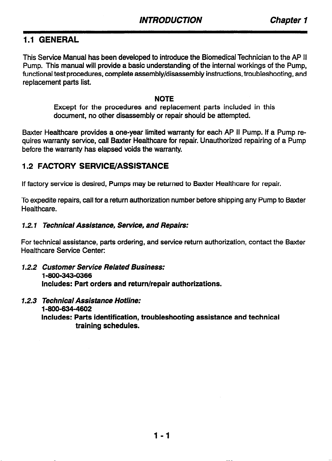
This Service Manual has been developed to introduce the Biomedical Technician to the AP II
Pump. This manual will provide a basic understanding of the internal workings of the Pump,
functional test procedures, complete assembly/disassembly instructions, troubleshooting, and
replacement parts list.
NOTE
Except for the procedures and replacement parts included in this
document, no other disassembly or repair should be attempted.
Baxter Healthcare provides a one-year limited warranty for each AP II Pump. If a Pump requires warranty service, call Baxter Healthcare for repair. Unauthorized repairing of a Pump
before the warranty has elapsed voids the warranty.
1.2 FACTORY SERVICE/ASSISTANCE
If factory service is desired, Pumps may be returned to Baxter Healthcare for repair.
To expedite repairs, call for a return authorization number before shipping any Pump to Baxter
Healthcare.
1.2.1 Technical Assistance, Service, and Repairs:
For technical assistance, parts ordering, and service return authorization, contact the Baxter
Healthcare Service Center:
1.2.2 Customer Service Related Business:
1-660-343-6366
Includes: Part orders and return/repair authorizations.
1.2.3 Technical Assistance Hotline:
14004344602
Includes: Parts identification, troubleshooting assistance and technical
training schedules.
l-1
Page 12

Chapter I INTRODUCTION
THIS PAGE INTENTIONALLY BLANK
1-2
Page 13
THEORY OF OPERATION Chapter 3
2.1 OVERVIEW OFTHE AP II PUMP
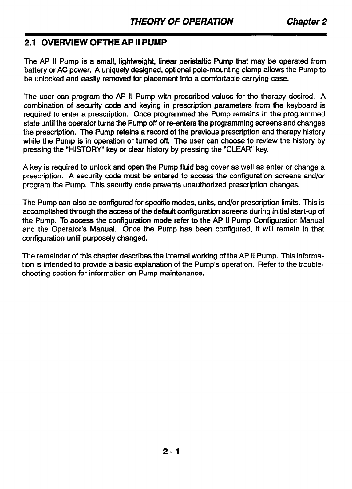
The AP II Pump is a small, lightweight, linear peristaltic Pump that may be operated from
battery or AC power. A uniquely designed, optional pole-mounting clamp allows the Pump to
be unlocked and easily removed for placement into a comfortable carrying case.
The user can program the AP II Pump with prescribed values for the therapy desired. A
combination of security code and keying in prescription parameters from the keyboard is
required to enter a prescription. Once programmed the Pump remains in the programmed
state until the operator turns the Pump off or reenters the programming screens and changes
the prescription. The Pump retains a record of the previous prescription and therapy history
while the Pump is in operation or turned off. The user can choose to review the history by
pressing the “HISTORY” key or clear history by pressing the “CLEAR” key.
A key is required to unlock and open the Pump fluid bag cover as well as enter or change a
prescription. A security code must be entered to access the configuration screens and/or
program the Pump. This security code prevents unauthorized prescription changes.
The Pump can also be configured for specific modes, units, and/or prescription limits. This is
accomplished through the access of the default configuration screens during initial start-up of
the Pump. To access the configuration mode refer to the AP II Pump Configuration Manual
and the Operator’s Manual. Once the Pump has been configured, it will remain in that
configuration until purposely changed.
The remainder of this chapter describes the internal working of the AP II Pump. This information is intended to provide a basic explanation of the Pump’s operation. Refer to the trouble-
shooting section for information on Pump maintenance.
2-1
Page 14
Chapter 2 THEORY OF OPERATION
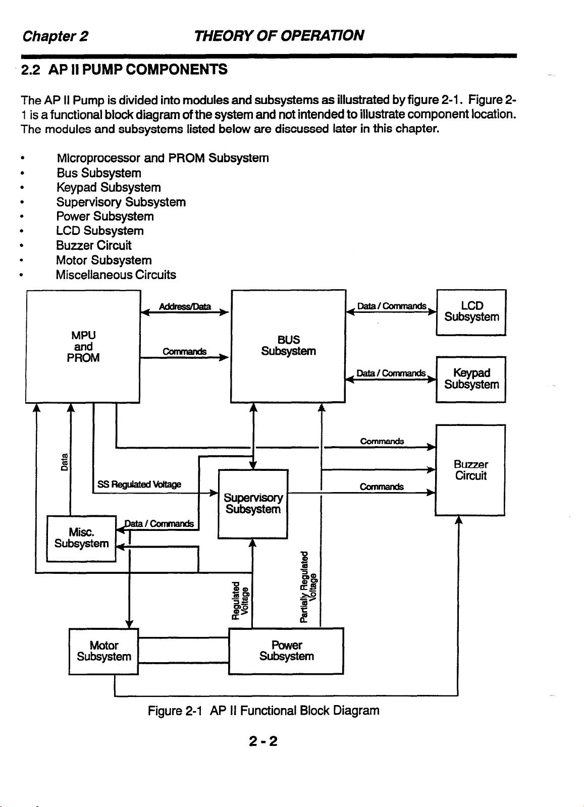
2.2 AP II PUMP COMPONENTS
The AP II Pump is divided into modules and subsystems as illustrated by figure 2-1. Figure 2-
1 is a functional block diagram of the system and not intended to illustrate component location.
The modules and subsystems listed below are discussed later in this chapter.
Microprocessor and PROM Subsystem
Bus Subsystem
Keypad Subsystem
Supervisory Subsystem
Power Subsystem
LCD Subsystem
Buzzer Circuit
Motor Subsystem
Miscellaneous Circuits
.
MPU
P%%
BUS
subsystem
T T
Figure 2-1 AP II Functional Block Diagram
Page 15
THEORY OF OPERATION Chapter 2
2.2. I Microprocessor and PROM Subsystem
The AP II Pump is controlled by a microprocessor executing from an external PROM. The
microprocessor is a 1 S-bit single-chip device with two modes of operation.
single chip mode whenever possible or in memory expansion mode when accessing devices
on the external bus. Running in the single chip mode saves power which is a major factor for
this Pump. The processor has eight input/output (l/O) ports which are used to control or
monitor the following functions:
It will operate in the
.
.
.
.
.
.
.
.
.
.
PROM
LCD Command and Data Register
Motor Drive
Watchdog
KeYPad
Switches
Buzzer Circuit
Real Time Clock Circuit
Occlusion Circuit
Various voltages
If an error is detected, the processor will initiate an error code which will produce an alert
message and audible alarm. A number of power-up tests are performed to ensure that the
Pump is running properly. The power-up tests include testing of the LEDs, beeper, backup
battery, and input voltages.
Included in the processor subsystem is the real time clock (RTC) circuit. The RTC provides
time of day information to the microprocessor. The RTC circuitry keeps track of time when the
Pump is off, through the use of a backup battery mounted to the microprocessor circuit board.
The backup battery is also used to preserve the contents of the microprocessor RAM when
operation power drops below a minimum voltage. The RTC also contains a small amount of
RAM which is used by the system software to determine whether there has been a loss of
backup battery power.
The PROM subsystem supplies data to the bus when addressed by the microprocessor to
identify the operation requested.
2-3
Page 16
Chapter 2
THEORY OF OPERAnON
2.2.2 BUS Subsystem
The BUS has the capacity to provide for a 24 bit address and 8 bit data path. The micropro-
cessor uses the BUS subsystem to transfer data or instructions to six different functions.
These six functions are:
.
.
.
.
.
.
PROM
LCD Command and Data Register
Motor Drive
Watchdog
Keypad
Switches
2.2.3 Keypad Subsystem
The keypad subsystem enables the user to enter the prescription data which is unique to each
usage, and to start and stop the device. The keypad subsystem is comprised of nine keys on
the membrane keypad and three other switches. The microprocessor samples each of the
keys and switches to determine their status. Each of the keys and switches are described
below:
KEY
START
STOP
ENTER
ON/OFF
CLEAR/SILENCE
HISTORY
Left Arrow Key
Up Arrow Key
Right Arrow Key
Primary Function
Starts operation of the unit.
Stops operation of the unit.
Accepts entered configuration codes, configuration parameters, and lim-
its.
Turns the Pump ON and OFF.
Clears data stored in history and silences the audio alarm.
Access the history screens to allow scrolling through history data.
Move the cursor to the left.
Scrolls a selected digit to the next higher setting.
Moves the cursor to the right.
SWITCH
PCA Jack
Bag Cover Lock
Tubing Sensor
Primary Function
Patient Controlled Analgesia (PCA) switch. The PCA switch is a phono
jack which is monitored by the microprocessor to determine the status of
the PCA button.
Internal switch that detects when the bag cover is locked or unlocked.
Switch that detects when the Pump tubing cover is open or closed with
tubing set properly installed.
2-4
Page 17
THEORY OF OPERATION Chapter 2
2.2.4 Supervisory Subsystem (SS)
The supervisory subsystem performs a major role in the start-up and shutdown of the Pump.
Monitoring and responding to error situations reported by hardware and software is also a
function of this circuitry. A “well check” is performed by the SS on some of the error detection
hardware circuitry.
The SS also provides the power for the microprocessor and the RTC. As long as the regulated
+5V remains above the backup battery voltage, the SS will produce a +5V source for the
microprocessor and the RTC. If the regulated +5V falls below the backup up battery voltage,
the SS connects the backup battery to the microprocessor and the RTC to preserve the
contents of the microprocessor RAM and provide power for RTC operation.
2.2.5 Power Subsystem (PS)
The power subsystem provides the required DC power for the AP II Pump from a 9 volt battery
or the AC Adapter. The AC Adapter is an external unit, which when plugged into an AC wall
outlet will produce 10 volts DC. The AC Adapter is connected, to the AP II Pump at its AC
Adapter input jack. When power is available from both the battery and AC Adapter, the PS
selects the AC Adapter by default to conserve battery life. The PS automatically switches the
LCD backlight to an increased intensity when the AC Adapter power is present.
The PS provides regulated, partially regulated, and unregulated power. In the event that both
the battery and AC Adapter are not present, the PS, in conjunction with the SS, will switch the
microprocessor and RTC power to the backup battery. This maintains the contents of the
microprocessor RAM and keeps the RTC operational.
The unregulated voltage is used primarily to power the motor that drives the AP II peristaltic
Pump. The partially regulated voltage is used to power the buzzer and the LCD’s backlight
circuit. The unregulated voltage is also used as a monitored voltage for the overvoltage fault
detector. The regulated voltage is supplied to all of the IC chips.
2.2.6 LCD Subsystem
The liquid crystal display (LCD) subsystem serves as a device for the microprocessor to
communicate with the user and facilitate the entry of data from the keypad. The LCD displays
two rows of 16 characters, with each character defined by a selection of dots from a 5 x 7 array
with a cursor underneath the array.
The LCD can be written to by the microprocessor which supplies it with either data or com-
mands. Information in the LCD’s memory is read by the microprocessor. For its functional
operation, the LCD has two memories; the character generator (CG) RAM and the display
data (DD) RAM. The AP II Pump hardware has no need to distinguish between the two RAMS.
This is accomplished by the software running in the microprocessor through the commands it
issues to the LCD.
2-5
Page 18
Chapter 2
2.2.7 Buzzer Circuit
The buzzer circuit provides an audio output to inform the user of the operational status. The
buzzer is accessible through an I/O port from the microprocessor, external hardware, and
software. Operational status and error conditions reported by the external interface devices
activate the buzzer to produce an audible alarm.
2.2.8 Motor Subsystem
The motor subsystem contains two drive paths to activate the Pump. The paths are known as
the positive and negative drive. The Pump drive paths are controlled very precisely by the
microprocessor with feedback from two independent shaft position encoders. The encoder
information enables precise control over the delivery rate.
To drive the motor, the positive signal must be asserted allowing the motor’s negative signal to
complete the return conduction path through the motor when it is activated. The motor’s posi-
tive and negative drive paths are enabled by the microprocessor through different ports.
THEORY OF OPERATION
2.3 MISCELLANEOUS CIRCUITS
2.3.1 Occlusion Detection Circuits
A check is made for the possibility of blockage (occlusion) during delivery downstream of the
AP II Pump. The elastic section of the tubing set (in the area where the fingers of the peristaltic
Pump operates) will expand slightly if a blockage exists. The expansion causes a switch to
trip enabling the Pump to sense an occlusion. However, before an occlusion is detected, the
Pump will check for a wet switch condition to reduce the occurrence of a false occlusion signal.
2.3.2 Backlight Circuit
The backlight circuit provides power for the light emitting diodes (LEDs) in the LCD unit to
generate the necessary light to read the display. Since these LEDs consume a significant
amount of power, the display is only lit when needed while being powered by the 9 volt battery.
The LEDs are driven at less than the nominal rated current. This provides a dim illumination
of the display to reduce the drain on the battery. When programming the unit on battery
power, the backlight will be on. Piieen seconds after programming is complete, the backlight
will turn off. The backlight will turn on again when a key is pressed.
When the Pump is being powered by the AC adapter, the LEDs are on all the time. The LEDs
are supplied with nominal full rated current giving a bright backlight. As long as the AC adapter
is providing power, the display will remain lit.
2-6
Page 19
THEORY OF OPERATION
2.3.3 Printer Adapter Intetface Circuit.
The interface to the printer adapter enables the microprocessor to produce a printout of the
history data. The Pump interfaces with the Baxter Printer Adapter, P/N 2L3400, and a printer
(typically a Seiko DPU-411). The printer interface is a serial port that operates on 7TL levels
and provides data at a 600 baud rate.
Chapter 2
2-7
Page 20

Chapter 2 THEORY OF OPERATION
THIS PAGE INTENTIONALLY BLANK
2-8
Page 21
INITIAL INSPECTION AND DAMAGE CHECK Chapter 3
3.1 GENERAL
This chapter contains the information necessary to perform an initial inspection and set up of
the AP II Pump. A functional test is included in Chapter 4 to determine if operation is satisfactory.
3.2 INITIAL INSPECTION AND DAMAGE CHECK
The AP II Pump has been thoroughly tested and inspected at the factory prior to shipment
and has been found to comply to Baxter’s electrical and mechanical standards. The API1
Pump has also been designed to reliably withstand normal shipment and usage conditions.
However, abusive handling during shipment may cause either visible or hidden damage.
Follow the instructions in this section before performing operational checks.
If any damage is observed in any of the following inspections, and this damage is related to
shipping, notify the carrier’s agent immediately. Do not return the damaged equipment to the
factory without written authorization.
3.3 INSPECTIONS
1. Carefully inspect the shipping carton before opening it. Note any obvious damage caused
by mishandling and record any such damage.
2. The carton should contain the following:
One AP II Pump with a 250E Fluid Bag Cover
One Patient Control Button
One Pump Carrying Case
One Operator’s Manual
One Quick Programming Guide
One Configuration Manual
Two Keys
One AC Adapter
3. Remove the Pump from the carton. Place the Pump on a flat surface and perform these
visual inspections:
A. Check the entire surface for chips, scratches, dents, or cracks.
B. Check the front keypad panel for damage.
C. Check the Fluid Bag Cover for cracks and check to see that it locks properly.
D. Turn the Pump over and verify that the serial number matches that on the shipping
carton. Refer to the Operator’s Manual for tracking information.
3-l
Page 22

Chapter 3 INITIAL INSPECTION AND DAMAGE CHECK
THIS PAGE INTENTIONALLY BLANK
3-2
Page 23

FUNCTIONAL TESTS Chapter
4
-
4.1 GENERAL
The AP II Pump design includes extensive self-tests which continually monitor the Pump’s
operation. These checks occur during normal operation of the device. When an alarm or
fault condition is detected, the Pump generates an alert message, flashing LED indicators
and/or an audible alarm. These indicators warn the user of the detected fault. The Pump will
stop operating until the fault condition has been corrected. This procedure provides tests that
are to be used to ensure that the Pump operates properly.
It is recommended that anyone performing this functional test become familiar with the device
operating procedures contained in the AP II Pump Operator’s Manual. If the Pump has been
configured in such a manner that this test cannot be followed, refer to the AP II Pump Con-
figuration Manual to re-configure the Pump to the factory defaults.
Pumps that fail are to be repaired per Chapter 6 of this manual or be returned to the Baxter
Service Center. Record the failure mode and the Pump’s setup prior to and during the failure
before returning the Pump. Call a Baxter representative for a service authorization number
and the procedure for returning a Pump for repair.
It is recommended that the functional test results be recorded on the provided Test Data
Sheet contained at the end of this Chapter. The Test Data Sheets should be kept as a
preventive maintenance record for each Pump.
4.1.1 Equipment Required
AP II Pump with battery installed
PCA Cable
AC Adapter
Tubing set
(2) 250 mL reservoir bags
Stopwatch or timer (minutes and seconds)
Fresh distilled water
Scale with minimum of two decimal place gram readout (for use with gravimetric test)
25 or 50 mL burette (for use with volumetric test)
4.1.2 Optional Equipment
l
Seiko DPU-411 Printer or equivalent
l
Printer Adapter (2L3400)
l
Printer Cable (2L3402)
4-l
Page 24

Chapter 4 FUNCTIONAL TESTS
4.2 VISUAL INSPECTION
The unit shall be inspected for the parameters listed below. Upon completion of the inspection, check off pass or fail on the Data Sheet and record any pertinent comments. If the Pump
fails any of these inspections, ensure that the applicable service is performed on the Pump
before being put to use.
1. Puma
casing
- Verify that the Pump casing is free of visible damage and free of any
indication of fluid ingress.
2. Baa cover - Verify that the bag cover is properly positioned and secure to the Pump.
Verify that it opens and closes freely and without binding.
3. Baa cover loc& - Verify that the bag cover locks and that the lock cam turns freely when
locking and unlocking the cover.
4. Tubina cover door - Verify that the tubing cover door opens freely and that the latching
mechanism operates properly when the door is closed.
5. Batter-v door - Verify that the battery door operates freely and closes securely when a
battery is in place.
6. Kewad
- Verify that the entire keypad is secured to the case and is not lifting up at the _
edges. Ensure that the keypad is free of damage.
7. Labels - Verify the presence of the following labels:
l
Rear label (on the rear case)
l
Serial no. label (also on the rear case)
l
Reorder label (on the inside of the bag cover)
l
Battery polarity label (inside the battery compartment)
4-2
Page 25

FUNCTIONAL TESTS Chapter 4
-.
4.3 FLOW RATE ACCURACY TEST
NOTES
A gravimetric method and a volumetric method have been provided. The performance of either method is acceptable. Record all appropriate information on
the Data Sheet.
The following procedure should be used to verify the flow rate accuracy of the
Ap II Pump. The performance of commercially available automated rate testing equipment has not been evaluated by Baxter for use on the AP II Pump.
Use of this equipment is therefore not recommended.
Test Set Up
1. Fill the reservoir bag with a minimum of 100 mL of distilled water using a syringe.
2. Remove all the air from the reservoir bag then cap it.
3. Install the tubing set into the pump.
4. Uncap the reservoir bag and attach it to the tubing set.
-
5. Install the bag into the Pump’s bag cover, close and lock the bag cover.
6. Program the Pump as follows:
Mode = Continuous
Units =mL
Bag volume
7. Prime the pump until all the air is removed from the tubing set and reservoir bag.
NOTE: To perform the test using the gravimetric method, proceed to section 4.3.1. To per-
form the test using the volumetric method, proceed to section 4.3.2.
4.3.1 Procedure using Gravimetric method
1. Set the scale to read in grams.
2. Attach the distal end of the tubing set to an empty 250 mL bag (output bag).
3. Deliver two additional priming volumes to ensure flow to the output bag.
= 100 mL
4. Disconnect output bag, cap it, weight it, and record this as the “start weight” on the Data
Sheet. After recording start weight, reconnect output bag to tubing.
4-3
Page 26

Chapter
5. Complete the Pump program as follows:
Rate = 10.0 mL/H
Bolus = 00.0 mL
6. Press “START” and start the stopwatch simultaneously.
7. After approximately 1 hour, simultaneously unlock the bag cover and stop the stopwatch.
Shut the Pump off.
8. Disconnect output bag, cap it, and weigh it. Record this weight as the ‘end weight”.
9. Record the stopwatch reading in seconds.
10. Use the following formulas to calculate the rate error:
4
test rate (mL/hr) = (end weiaht) - (start weight) X 3600
FUNCTIONAL TESTS
elapsed time
rate error (%) = 10 - test rate X 100
10
Record the test rate and the rate error on the Data Sheet.
11. If the rate error is equal to or less than 1 O%, the Pump passes this test. Otherwise, the
Pump fails. Record the results on the Data Sheet.
4.3.2 Procedure using Volumetric method
1. Attach the distal end of the tubing set to a 25 or 50 mL burette.
2. Deliver two additional priming volumes to ensure flow to the burette.
3. Record the volume reading on the burette as the ‘start volume” on the Data Sheet.
4. Complete the Pump program as follows:
Rate = 10.0 mL/H
Bolus
= 00.0 mL
5. Press “START” and start the stopwatch simultaneously.
6. After approximately 1 hour, simultaneously unlock the bag cover and stop the stopwatch.
Shut the Pump off.
4-4
Page 27

FUNCTIONAL TESTS Chapter 4
7. Record the volume reading on the burette as the “end volume”.
8. Record the stopwatch reading in seconds.
9. Use the following formulas to calculate the rate error:
test rate (mL/hr) = difference between end and start volumes
elapsed time
rate error (%) = 10 - test rate X 100
10
Record the test rate and the rate error.
IO. If the rate error is equal to or less than lo%, the Pump passes this test. Otherwise, the
Pump fails. Record results on the Data Sheet.
X 3600
4-5
Page 28

Chapter 4
4.4
MISCELLANEOUS CHECKS
This section (4.4) is designed to perform tests on the following Pump features: Tubing sensor, Occlusion switch, PCA cable, AC adapter, history retention and printer feature (optional).
This section is also designed to be performed as one continuous operation. Record the
results of each test on the Data Sheet.
Test Set Up
1. Remove the tubing set from the Pump.
2. Plug the PCA cable into the Pump.
3. Plug the AC adapter into the Pump.
4. Ensure a 9 volt battery is installed into the Pump.
FUNCTIONAL TESTS
4.4.1
Procedure
1. Program the Pump as follows:
2.
3. The screen should display “CHECK TUBING PLACEMENT”, the red LED should be
4.4.2 Occlusion Switch Test
Procedure
Tubing Sensor Test
Mode = BASAL + PCA
Units =mL
Bag volume = 100 mL
At the “START TO PRIME, ENTER TO PROCEED” screen, press “START”.
flashing and the audible alarm should be sounding. If so, the Pump passes this test. (The
“CLEAR/SILENCE” key may be pressed to silence the alarm.) Record the results on the
Data Sheet.
1. Unlock the bag cover.
2. The screen should display “BAG COVER IS UNLOCKED”, the red LED should be flashing and the audible alarm should be sounding. (The ‘CLEAR/ SILENCE” key may be
pressed to silence the alarm.)
3. Open the bag cover, open the tubing cover and install a tubing set into the pump.
4-6
Page 29

FUNCTIONAL TESTS Chapter 4
-
4. Close and lock the bag cover. The security code screen should appear.
5. Program the Pump as follows:
Mode = BASAL + PCA
Units =mL
Bag volume = 100 mL
6.
At the
“START TO PRIME, ENTER TO PROCEED”
screen, clamp the distal end of the
tubing set within about 3 inches from the Pump. Press “START”.
7. Before the end of the .5mL priming cycle, the display should read “DOWN STREAM
OCCLUSION”, the red LED should be flashing and the audible alarm should be sounding. If so, the Pump passes this test. If not, check that the tubing set is properly clamped
and repeat the priming cycle. If the Pump still does not go into the Occlusion alarm mode,
repeat the priming cycle for a total of 5 times. If the Pump, still does not go into the
Occlusion alarm mode after the fifth priming cycle, the Pump fails this test.
8. Record the results on the Data Sheet.
4.4.3
PCA Cable Test
Procedure
1. At the end of the priming cycle of the previous test, the screen should read “STARTTO
PRIME, ENTER TO PROCEED”.
2. Press “ENTER” and enter the remainder of the prescription as follows:
PCA dose = 1 .O mL
Delay = 3 minutes
Basal rate = 5.0 mlJH
1 Hr. limit = 20.0 mL
Bolus = OO.OmL
3.
Press
“START”.
The display should now read “BASAL + PCA” and the green LED
should be flashing.
4. Wait a minimum of 3 minutes then press the PCA cable button 4 times. The Pump should
beep every time the PCA cable button is pressed.
5. Unplug the PCA cable from the pump. The screen should display “PCA CONNECTOR
NOT INSERTED”, both LED’s should be flashing and the audible alarm should be sounding.
4-7
Page 30

Chapter 4 FUNCTIONAL TESTS
6. Re-insert the PCA cable into the pump. The screen should now display “BASAL + PCA”,
the green LED should be flashing and the alarm should be off.
7. If all the observations in steps 4, 5 and 6 have occurred, the Pump passes this test.
Record the results on the Data Sheet.
4.4.4 AC Adapter Test
Procedure
1. Disconnect the AC adapter from the Pump. The backlighting should turn off and after
approximately 2 seconds, the Pump will beep 3 times and the icon in the upper right hand
corner of the display will change to the battery symbol.
2. Reconnect the AC adapter into the Pump. The backlight will turn on and the screen icon
will change to the plug symbol.
3. If all the observations in steps 1 and 2 have occurred, the Pump passes this test. Record
the results on the Data Sheet.
4.4.6 History Retention Test
Procedure
1. Turn the Pump off, unplug the AC adapter and remove the 9 volt battery. After approximately 1 minute, re-insert the 9 volt battery and the AC adapter and turn the Pump on.
2. Scroll through the history screens as described in the AP II Pump Operator’s Manual.
Verify that the prescription is correct and that the INJ/ATT screen indicates 1 INJ 4 ATT.
3. If the history screens are accurate, the Pump passes this test. Record the results on the
Data Sheet.
4.4.6 Printer Test (Optional)
Procedure
1. Connect the Printer Adapter to the printer.
2. Insert the Printer Cable to the Printer Adapter and the AP II Pump printer connector.
3. Turn on the printer.
4. Ensure that the active light is illuminated on the Printer Adapter.
4-8
Page 31

FUNCTIONAL TESTS Chapter
5.
Press
6. Verify that the Pump provides an AP II history printout.
7. If the printout is accurate, the Pump passes this test. Record the results on the Data
Sheet.
“PRINT/STOP”
key on the Printer Adapter.
4
4-9
Page 32

Chapter
4.5
4
FUNCTIONAL TEST DATA SHEET
FUNCTIONAL TESTS
Record the results of the AP II Pump functional
reproduced. Pumps that fail any of these tests must be serviced before being put to use.
AP II PUMP S/N:
1
PASS FAIL
4.3 FLOW
Start Weight End Weight Elapsed Time
Start Volume End Volume Elapsed Time
HARDWARE REV:
4.2 VISUAL
RATE ACCURACY TEST
4.3.1
Gravimetric Method
Test Rate
I
Volumetric Method
Test Rate
I
tests on this Data Sheet. This sheet may be
SOFTWARE REV.
INSPECTION
COMMENTS
Results
Rate Error
PASS
Results
Rate Error -
PASS FAIL
--1
FAIL
-
Comments:
4.4 MISCELLANEOUS
Feature
4.4.1 Tubing Sensor Test
4.4.2 Occlusion Switch Test
4.4.3 PCA Cable Test
4.4.4 AC Adapter Test
4.4.5 History Retention Test
4.4.6 Printer Test (Optional)
Test Results
PASS
I I I
CHECKS
Comments
FAIL
Signature: Date:
4
* 10
Page 33

ROUTINE MAINTENANCE
5.1 General
The Pump is designed to provide reliable service with only minor routine maintenance. A
periodic functional inspection of the Pump should be made at least every six months to assure proper operation. The Pump should be cleaned and disinfected if necessary, according
to frequency of use and hospital protocol.
5.2 Cleaning and Disinfecting
The exterior surfaces of the AP II Pump may be cleaned with a cloth, sparingly dampened
with any of the cleaners listed in the table below. Follow manufacturer‘s dilution instructions
for concentrated cleaners. Used Pumps should be cleaned/disinfected with an agent from
the list below before use on another patient. Spills and dirt should be cleaned off the Pump as
quickly as possible.
Table 5-1 Approved Cleaners and Disinfectants
Chapter 5
Cleaner
Soapy water
A solution of 10% bleach and water
LPH
Septisol
Cidex 7
Super Edisonite
TOR or Hi-TOR Plus
Bafix
Manufacturer
N/A
N/A
Vestal Labs
I
Vestal Labs
I
Surgikos
I
Edison Chemical
I
Huntington Labs
Hysan Corporation
The AP II Pump and AC adapter are not waterproof and should not be
immersed. Avoid getting liquids inside the Pump or permanent damage
may resutt. Do not use alcohol for cleaning. Sterilization via ETO, steam,
etc. should not be attempted.
5-I
Page 34

Chapter 5
ROUTINE MAINTENANCE
THIS PAGE INTENTIONALLY BLANK
5-2
Page 35

TROUBLESHOOllNG AND REPAIR Chapter 6
6.1 GENERAL
Pumps under warranty must be returned to the factory for troubleshooting and repair. Unauthorized disassembly/repair will void your warranty. When a Pump is malfunctioning, petform
the following to see if Pump operation can be restored. Ensure that the:
l
batteries are installed and not depleted.
l
batteries are installed correctly (proper polarity).
l
patient control switch is properly installed.
If this does not restore the Pump to operation refer to the troubleshooting chart later in this
chapter.
There are no internal user repairable parts available. The Pump must
only be serviced by a trained biomedical engineering technician or Baxter
Healthcare personnel.
6.2 TROUBLESHOOTING
The troubleshooting procedure and tables in this section are written for repair to the board
level. Except for those items listed, circuit board components are not available from Baxter
Healthcare. Refer to Chapter 7 for disassembly procedures and Appendix C for part informa-
tion.
6.2. I Board Exchange
A board exchange program is available for the circuit board assembly in the AP II Pump.
Baxter Healthcare provides a refurbished board in exchange for a returned defective board.
Boards which are damaged through unauthorized rework, missing components, or improper
maintenance will not be eligible for this program. Call customer service for an authorization
number prior to shipping the defective board.
6.2.2 Mechanism Exchange
Due to the manufacturing process for the mechanism, this assembly cannot be repaired in
the field. An exchange program has been established to facilitate cost effective repairs. This
program provides a credit for return of a defective mechanism assembly when a refurbished
mechanism assembly is ordered. This program is not available when ordering a new mechanism assembly. Call customer service for an authorization number prior to shipping the de-
fective mechanism.
6-I
Page 36

Chapter 6 TROUBLESHOOTING AND REPAIR
6.2.3 Tools and Equipment
The following list of tools are recommended for use in maintaining and troubleshooting the
AP II Pump. The troubleshooting chart assumes that these tools or their equivalent are
available for use.
l
Oscilloscope
l
Wire Cutters
l
ESD Protection Station
l
Soldering Iron
6.2.4 Troubleshooting Tips
Table 6-1 Troubleshooting Chart
l
Screwdriver (Cross point)
l
Permabond 792 Adhesive
l
Tubing Set
l
Resenroir
Symptom Possible Cause
No Power (9V)
Dead battery Check/replace 9 volt battery.
Broken battery leads
Defective MPU board
No Power (AC) Poor AC power adapter
connection to Pump
Defective AC power adapter
Defective power connector
in Pump
Solution
Replace battery contact assembly.
Check for 9 volt line at J10 connector (See Appendix B, #5). If
present, replace MPU board. If not,
replace battery contact assembly.
Ensure that the red dots are
aligned and connector is plugged
in fully.
Check output of Power Adapter for
10 VDC. Replace AC Adapter.
Check for proper installation of the
AC power connector onto the MPU
board at 54 (See Appendix B, #6).
Replace the Front Case Assembly.
-
Defective MPU board Check for 10 volts at J4 connector.
No Audio Alarm Defective buzzer
Defective MPU board
If present, replace MPU board. If
not, replace Front Case Assembly.
Replace buzzer.
Replace MPU Board.
6-2
Page 37

TROUBLESHOOTING AND REPAIR Chapter 6
Symptom Possible Cause Solution
No occlusion alarm or Defective occlusion switch Check for continuity between pin 8
constant occlusion
alarm
Defective MPU board Replace MPU board.
and 9 of the mechanism while
manually activating the occlusion
switch. Replace mechanism assembly if defective.
LCD not working or
segments missing.
No backlighting Poor connection Check to ensure backlight connec-
“Check tubing
placement” screen
will not clear.
Bent/broken pin on LCD
board
Defective LCD board
Defective MPU board Replace MPU board.
Defective LCD board Replace LCD board.
Defective MPU board Replace MPU board.
Tubing segment improperly
installed or not installed
Defective microswitch With tubing segment properly in-
Replace gold pin connector.
Replace LCD board.
tor is properly installed.
Assure tubing set is installed properly. Refer to Operator’s Manual
for proper installation.
stalled, check for continuity between pin 7 and 8 of mechanism.
If circuit remains “open”, replace
mechanism assembly.
Defective MPU board Replace MPU board.
“Bag cover is Defective reed switch Replace rear case half assembly.
unlocked” alarm will
not clear.
Defective lock assembly
Defective MPU board Replace MPU board.
Repair / replace reservoir cover.
6-3
Page 38

Chapter 6 TROUBLESHOOTING AND REPAIR
Symptom
No input from front
panel keypad
Will not retain memory Low or dead 3V battery
Will not accept
attempts/injections
from PCA switch.
Will not print out. Defective printer connector
Possible Cause
Defective keypad
Defective
Defective PCA Cable
Defective PCA connector
Defective MPU board
MPU board Replace MPU board.
Solution
With power removed, check key-
pad for continuity while pressing
the suspected key (refer to schematic).
Replace 3V battery. See 3V bat-
tery replacement in section 7.2.5.
Replace PCA Cable.
Replace PCA connector.
Replace MPU board.
Check for bent printer pins. Replace if necessary.
6-4
Page 39

TROUBLESHOOTING AND REPAIR Chapter 6
6.2.5 System Error Codes (Failure Codes)
Below is a listing of all error codes that the AP II Pump can generate. Refer to the Troubleshooting Chart (Table 6-1) for corrective action should one of these alarms occur. This list is
provided for reference purposes only.
CODE Description
NOTE
If an error code should appear, remove all power and restart the Pump.
A problem is indicated if the alarm persists. Due to the fact that error
codes shutdown the unit, it is difficult to troubleshoot without swapping
out suspected assemblies. As all error codes are software generated,
the MPU board is always suspect.
EOI -E09
El0
El l-El4
El5
El6
El7
El8
El9
E20
E21
E22
E23
E24
E25
E26
E27
E28-E29
E30
E31
E32
E33
E34
E35
E36
E37
E38
E39
Not used.
Keypad button held down more than 6 minutes.
Not used.
LCD display is not responding expeditiously.
Red LED is not functioning.
Not used.
Green LED is not functioning.
LCD display returned incorrect RAM pattern.
EEPROM acknowledge not received when expected.
Trying to read/write beyond EEPROM memory.
EEPROM write cycle time-out.
Error while printing history data.
Pump turned on by other than ON key.
CRC failure on internal ROM (8000-FFFF).
CRC failure on external ROM (20000-3FFFF).
External watchdog circuitry failure.
Not used.
No forward motion after several control intervals.
Motor runaway.
Can’t reach desired speed.
Main encoder counts 25% over nominal value for one motor rev.
Main encoder counts 25% under nominal value for one motor rev.
Main encoder counts 3% over nominal value for eight motor revs.
Main encoder counts 3% under nominal value for eight motor revs.
Not used.
Motor moving when motor should be stopped.
Motor drive transistor failure.
6-5
Page 40

Chapter 6
TROUBLESHOOTING AND REPAR
CODE
E40
E41
E42
E43
E44-E49
E50
E51 -E54
E55
E56
E57-E59
E60
E61 -E63
E64
E65-E69
E70
E71
E72
E73-E74
E75
E76
E77
E78
E79
Description
Not used.
Excessive motor back counts.
Speed nearing mechanical limits.
Motor not stopping quick enough.
Not used.
RTC vs system clock comparison error.
Not used.
Time read back != time written.
RTC RAM failure.
Not used.
Power supply voltage out of range.
Not used.
No detectable power source.
Not used.
Analog to digital converter time-out.
Illegal interrupt.
Internal watchdog time-out.
Not used.
BUS-COUNT exceeds maximum limit.
Unknown event received by task.
Tried to remove total not in list.
Software Timer Out of Range.
BO-isr held off for more than 60 ms.
E80
E81
E82
E83
E84
E85
Ea6
E87
Eaa-Ea9
Stack overflow.
Variable out of range.
UIT message buffer overflow.
STOP-RX routine called when it should not have.
Delivery attempt made before delay time elapsed.
Attempted to stop injection when no injection in progress.
Volume delivered not within &0.5%.
Attempt to infuse at 0 rate.
Not used.
6-6
Page 41

TROUBLESHOOTING AND REPAIR
Chapter 6
CODE
EQO
E91
E92
E93
E94
E95
E96
E97-EQQ
Description
UIT state transition error.
History checksum failure, data corrupted.
Error in getting RX data for printing.
Configuration checksum failure, data corrupted.
Rx checksum failure, data corrupted.
Unexpected data value.
LCD string length too long.
Not used.
6-7
Page 42

Chapter 6 TROUBLESHOOTING AND REPAIR
THIS PAGE INTENTIONALLY BLANK
6-8
Page 43

DISASSEMBLY/ASSEMBLY PROCEDURES
Chapter
7
7.1 GENERAL
This chapter contains a detailed description of the disassembly and assembly procedure for
the AP II Pump. Contact Baxter Healthcare if you have any questions while servicing the AP
II Pump.
pq
When performing the procedures of this chapter, exercise extreme caution
during disassembly to protect the circuit boards from static discharge.
The inspection or repair station, all equipment, and personnel should be
properly grounded.
NOTE
During disassembly, note the orientation and routing of all cables and
connectors. Failure to do so may result in improper operation and/or
damage to the Pump upon reassembly.
NOTE
During disassembly, keep track of all hardware and avoid leaving loose
hardware in the Pump upon reassembly. Failure to do so may result in
improper operation and/or electrical damage to the circuit board.
NOTE
After a component is reassembled it must be aligned or adjusted per the
procedure listed as its retest requirement.
NOTE
All Pumps must pass the functional tests in chapter 4 after repair is
complete.
7.2 DISASSEMBLY PROCEDURES
The procedure to assemble a component is the reverse of the disassembly unless otherwise
noted.
Numbers in parenthesis refer to the numbered parts of the drawing associated with the procedure.
Prior to disassembly, remove all accessories and batteries.
Page 44

Chapter 7
7.2. I Reservoir Assembly
1. Unlock and operi the Reservoir Assembly (1).
2. Remove the 3 pan head screws (3). Save the screws for use during assembly.
3.
To remove the Mounting Plate (4), remove the two screws (2) that secure it to the
Reservoir (1).
DISASSEMBLY/ASSEMBLY PROCEDURES
Figure 7-1 Reservoir Assembly Removal
7-2
Page 45

DISASSEMBLY/ASSEMBLY
7.2.2 Rear Case Half Assembly
1. Remove the Reservoir Assembly by following the procedure in section 7.2.1.
Place the Pump face down on a flat clean surface.
2.
3. Remove the 6 screws (2) and flat washers (3) from the Rear Case Half (1).
pq
Do not pull the Rear Case Half away from the unit very far. The Rear
Case Half has a circuit board mounted to it. The circuit board is connected
to the remainder of the unit via a semi-rigid PC board (4).
must be taken to prevent any damage to the semi-rigid PC board. To
remove the circuit board from the rear case refer to MPU Circuit Board
Removal (7.2.4) later in this chapter.
4.
Gently lift the Rear Case Half (1) from the rest of the Pump assembly and lay over on its
back.
NOTE
PROCEDURES
Extreme care
Chapter 7
When reassembling the Rear Case Half, make sure the Mechanism
ribbon cable is not overlapping the Battery Wall.
Figure 7-2 Rear Case Half Assembly
7-3
Page 46
Chapter
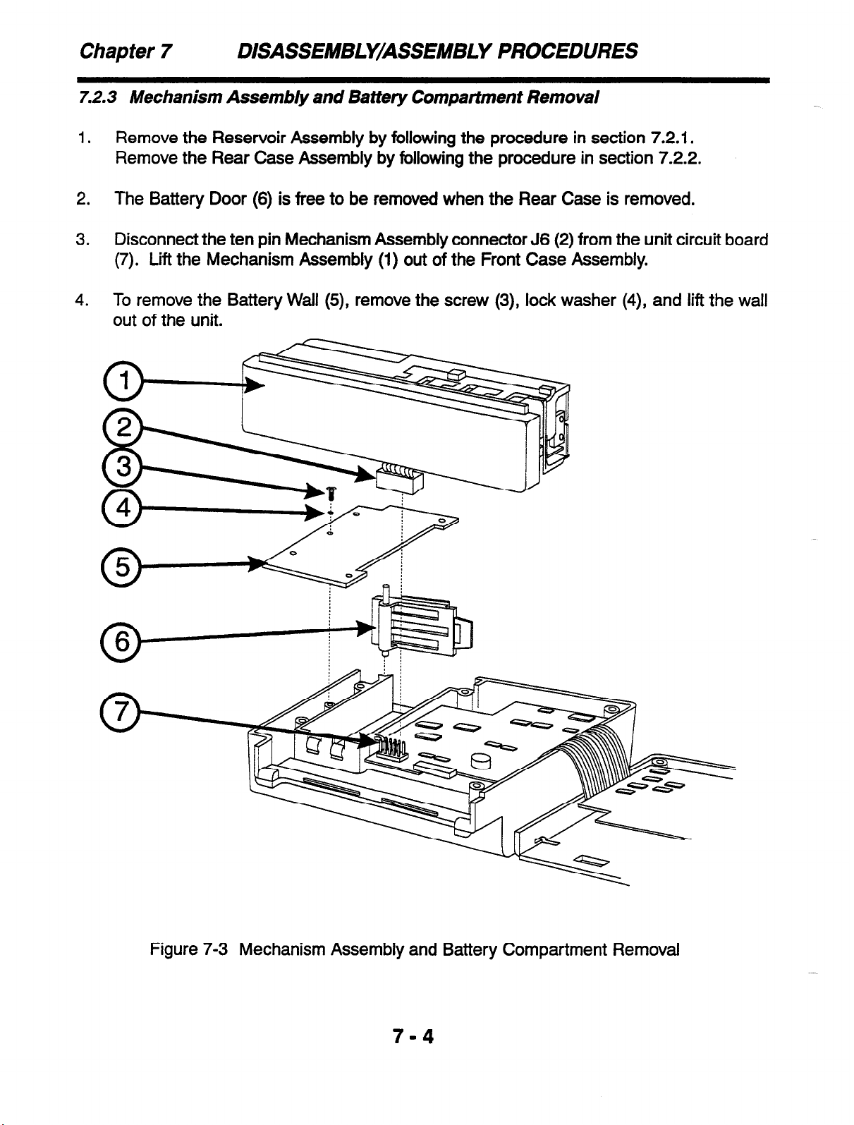
7.2.3 Mechanism Assembly and Battery Compartment Removal
1.
Remove the Reservoir Assembly by following the procedure in section 7.2.1.
Remove the Rear Case Assembly by following the procedure in section 7.2.2.
2. The Battery Door (6) is free to be removed when the Rear Case is removed.
3.
Disconnect the ten pin Mechanism Assembly connector J6 (2) from the unit circuit board
(7). Lift the Mechanism Assembly (1) out of the Front Case Assembly.
4.
To remove the Battery Wall (5), remove the screw (3), lock washer (4), and lift the wail
out of the unit.
7
DISASSEMBLY/ASSEMBLY PROCEDURES
Figure 7-3 Mechanism Assembly and Battery Compartment Removal
Page 47
DISASSEMBLY/ASSEMBLY PROCEDURES Chapter 7
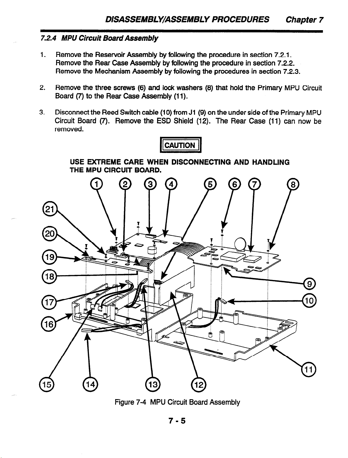
7.2.4 MPU Circuit Board Assembly
1.
Remove the Reservoir Assembly by following the procedure in section 7.2.1.
Remove the Rear Case Assembly by following the procedure in section 7.2.2.
Remove the Mechanism Assembly by following the procedures in section 7.2.3.
2. Remove the three screws (6) and lock washers (8) that hold the Primary MPU Circuit
Board (7) to the Rear Case Assembly (11).
3. Disconnect the Reed Switch cable (10) from Jl (9) on the under side of the Primary MPU
Circuit Board (7). Remove the ESD Shield (12). The Rear Case (11) can now be
removed.
pq
USE EXTREME CARE WHEN DISCONNECTING AND HANDLING
THE MPU CIRCUIT BOARD.
Figure 7-4 MPU Circuit Board Assembly
Page 48

Chapter 7 DISASSEMBLY/ASSEMBLY PROCEDURES
NOTE
If Backup Battery replacement is required, proceed to section 7.2.5.
4.
Disconnect the ten pin keypad cable (5) from J8/J9 (3) on the Secondary MPU Circuit
Board (4). Disconnect the two pin battery cable (17) from Ji 0 (2) on the Secondary MPU
Circuit Board (4) and remove the Battery Contact Assembly (15).
5.
Remove the three screws (1) and lock washers (8) that hold the Secondary MPU Circuit
Board (4) to the Front Case Assembly (16). Gently lift the Secondary MPU Circuit Board
(4) out of the Front Case Assembly (16).
NOTE
There is a 14 pin connection between the Secondary MPU Circuit Board
(4) and the LCD Circuit Board at J7. When reinstalling, ensure that these
pins line up correctly.
6.
Disconnect the two pin cable (13) coming from the LCD Module from J2 (18) on the
under side of the Secondary MPU Circuit Board (4).
7.
Disconnect the two pin AC connector (14) from J4 (20) of the Connector Circuit Board
(19).
8.
Remove the four screws (21) and lock washers (8) that hold the Connector Circuit Board
(19) to the Front Case Assembly (16). The MPU Circuit Assembly can now be lifted from
the case.
7-6
Page 49

DISASSEMBLY/ASSEMBLY PROCEDURES Chapter 7
7.2.5 3V Backup Battery Replacement
1.
Perform steps 1, 2, and 3 of section 7.2.4.
2.
Remove the 2-pin jumper connector (1) Ji 1, next to the Backup Battery (2).
Figure 7-5 Backup Battery Replacement
3.
Carefully flip the Front Case/MPU Board Assembly and desolder the Battery from the
board.
4.
Solder the replacement Battery to the board.
5.
Carefully flip the entire assembly back over.
6.
Connect the Reed Switch cable to Jl on the underside of the MPU Board (see step 3 of
section 7.2.4). Mount the MPU Board back to the Rear Case (see step 2 of section
7.2.4).
7.
Re-assemble the Battery Wall to the Front Case (see step 4 of section 7.2.3).
Re-assemble the Mechanism Assembly to the Front Case and MPU Board (see step 3
8.
of section 7.2.3).
9.
Re-install the ESD Shield into position (see step 3 of section 7.2.4).
Re-insert the Battery door into position (see step 2 of section 7.2.3).
10.
11.
Snap the Rear Case Assembly onto the Front Case Assembly and temporarily hold the
Case Halves in place with one of the six rear case mounting screws (see step 3 of section
7.2.2).
12.
The Backup Battery must be initialized as follows:
Insert a 9V Battery into the Pump and press the ON/OFF key to power up the Pump.
13.
After the self-test is complete, remove the rear case screw, open the rear
install the 2-pin jumper connector (1) onto Jl 1 on the board.
7-7
case and
Page 50

Chapter 7 DISASSEMBLY/ASSEMBLY PROCEDURES
7.2.6 LCD Circuit Board Assembly
1.
Remove the Reservoir Assembly by following the procedure in section 7.2.1.
Remove the Rear Case Assembly by following the procedure in section 7.2.2.
Remove the Mechanism Assembly by following the procedure in section 7.2.3.
Remove the MPU Circuit Board Assembly by following the procedure in section 7.2.4.
2.
Remove the screw (2), lock washer (3), and three standoffs (I) that secure the LCD
Circuit Board (4) to the Front Case Assembly,
3.
Lift the LCD Circuit Board Assembly clear of the Front Case Assembly.
Figure 7-6 LCD Circuit Board Assembly
7-8
Page 51

DISASSEMBLY/ASSEMBLY PROCEDURES
7.2.7 Keypad
1. Remove the Reservoir Assembly by following the procedure in section 7.2.1.
Remove the Rear Case Assembly by following the procedure in section 7.2.2.
Remove the Mechanism Assembly by following the procedures in section 7.2.3.
Remove the MPU Circuit Board Assembly by following the procedures in section 7.2.4.
Remove the LCD Circuit Board Assembly by following the procedures in section 7.2.6.
NOTE
A keypad cannot be reused after it has been removed.
2. Turn the Front Case (3) over with the Keypad (1) facing up. Lift the corner of the Keypad
(1) and carefully peel the Keypad (1) from the Front Case (3).
3. Carefully pry off the Keypad Cover (2) from the Front Case (3).
4. Clean off the adhesive from the Front Case (3).
Chapter
7
Edge of Cover must be against
this edge of the opening
Figure 7-7 Keypad Assembly
Re-Assemblv Notes
Remember to insert the Keypad tail through the Front Case opening before adhering the
1.
Keypad Cover (2) in place.
2. Use Permabond 792 adhesive to adhere the Keypad Cover (2) to the Front Case (3).
Allow the adhesive to set for a minimum of one minute.
3. Do not allow the Keypad adhesive to contact the Front Case (3) until the Keypad (1) is in
proper position.
7-9
Page 52

Chapter 7 DISASSEMBLY/ASSEMBLY PROCEDURES
THIS PAGE INTENTIONALLY BLANK
7-10
7
Page 53

SCHEMATIC DMGRAM Appendix A
A.1 GENERAL
This appendix contains the schematic diagram necessary for the technician to work on the AP
II Pump.
KEYPAD
J8 and J9
(see glow)
10 PIN
LCD BOARD
14 PIN AT 57
2 PIN AT 52
W=JGHT)
1 2~ , a 2PIN
I I I I
2 PIN
i
I
I
I- Lp!- A
AC
CONNECTOR
54
-----
1 ; ADAPTER I
I-------J
r--------
I PRINTER
A~~~~O;y 1
I
I
--------A
55 I
I
I
I
I
I
J9
PIN-OUT DETAIL FOR KEYPAD
J6 ’ 7 5 3 ’
10 8 8 4 2
PIN-OUT DETAIL FOR MECHANISM (MOTOR)
I I
A-l
Page 54

Appendix A SCHEMATIC DIAGRAM
THIS PAGE INTENTIONALLY BLANK
A-2
Page 55

CIRCUIT BOARD ASSEMBLY DRAWING Appendix B
B.l GENERAL
This appendix contains the circuit board assembly drawing for the AP II Pump. A table of
contents for this section is shown below:
Drawing Number
6465609 ASSY, PCB Al MPU FINAL
Description
B-1
Page 56

Appendix B
CIRCUIT BOARD ASSEMBLY DRA WING
6465609 ASSY, PCB Al MPU FINAL
B-2
1
Page 57

REPAIR PARTS
Appendix C
-
c.1 GENERAL
This appendix contains a part listing of the components of the AP II Pump. There are three
part list types contained in this appendix, by major component, alphabetical, and numerical.
The numerical and alphabetical lists are cross referenced to the assembly specific parts list
by figure and index number.
C.2 ASSEMBLY PART LISTINGS
This section is broken down as follows:
A)
B)
Cl
D)
El
Reservoir Assembly
Rear Case Half Assembly
Mechanism Assembly and Battery Compartment
MPU Board Assembly and ESD Shield
LCD Circuit Board Assembly and Front Case Half Parts
C-l
Page 58

Appendix C REPAIR PARTS
C.2. I Reservoir Assembly
Table C-A Reservoir Assembly Parts
Figure
ID Number
Al
A2
A3
A4
T
250 mL Extended Bag Holder Assembly
or
250 mL Bag Holder Assembly
or
100 mL Bag Holder Assembly
(All of the above p/n’s include items A2 and
#6 x 5/l 6” Self-Tap Screws
2-56 x
Mounting Plate
l/4"
Pan Head Screws
Description
A4)
I I
Baxter Part
Number
6465635
6465650
6465640
5101180
5101101
6465644
-
/ Quantity per
Assembly
1
1
1
2
3
1
A4
0
Figure A Reservoir Assembly Parts
c-2
Page 59

C.2.2 Rear Case Half
REPAIR PARTS Appendix C
Table C-B Rear Case Half Parts
Figure
ID Number
Bl Rear Case Assembly
(includes item B4)
82
83 #2 Flat Washer
B4
2-56 x 3/8” Pan Head Screws 5101103 6
Rear Label
Description Baxter Part Quantity per
Number Assembly
6465578RP 1
5143011 6
6465561 1
Figure B Rear Case Half Parts
c-3
Page 60
Appendix C REPAIR PARTS
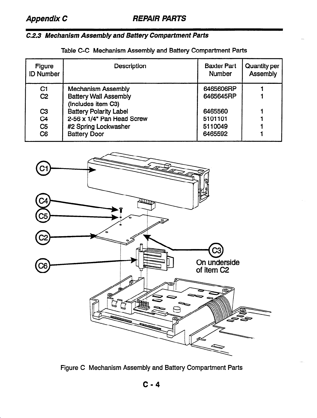
C.2.3 Mechanism Assembly and Battery Compartment Parts
Table C-C Mechanism Assembly and Battery Compartment Parts
Figure Description
ID Number Number Assembly
Cl
c2 Battery Wall Assembly 6465645RP 1
c3 Battery Polarity Label
c4
c5
C6
Mechanism Assembly 6465606RP 1
(Includes item C3)
2-56 x l/4” Pan Head Screw 5101101 1
#2 Spring Lo&washer 5110049 1
Battery Door 6465592 1
Baxter Part Quantity per
6465560 1
On underside
Figure C Mechanism Assembly and Battery Compartment Parts
c-4
Page 61
REPAIR PARTS Appendix C
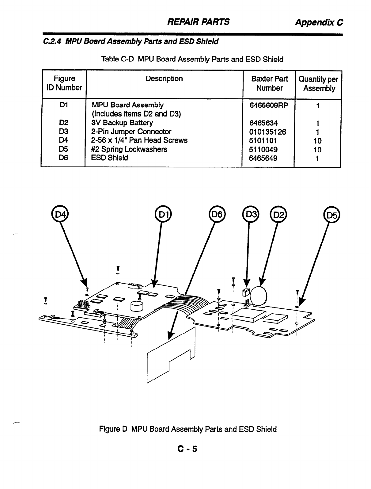
C.2.4 MPlJ Board Assembly Parts and ESD Shield
Table C-D MPU Board Assembly Parts and ESD Shield
Figure
ID Number
Dl
D2
D3
D4
D5
D6
Description
MPU Board Assembly
(Includes items D2 and D3)
3V Backup Battery
2-Pin Jumper Connector
2-56 x l/4” Pan Head Screws
#2 Spring Lockwashers
ESD Shield
Baxter Part
Quantity per
Number Assembly
6465609RP 1
6465634 1
010135126
1
5101101 10
5110049
10
6465649 1
Y
-
Figure D MPU Board Assembly Parts and ESD Shield
c-5
Page 62

Appendix C REPAIR PARTS
C.2.5 LCD Circuit Board Assembly and Front Case Half Parts
Table C-E LCD Circuit Board Assembly and Front Case Half Parts
Figure Description
ID Number Number Assembly
El LCD Circuit Board Assembly 6465624RP 1
E2 2-56 Standoffs 5125114 3
E3 2-56 x l/4” Pan Head Screws 5101101 1
E4
E5 Front Case W/O Board Assembly 6465590RP 1
E6
E7
E8
#2 Spring Lockwasher 5110049 1
(Includes items E7 and E8)
Battery Contact Assembly 6465570RP 1
Keypad Assembly 6465540RP 1
(Includes item E8)
Keypad Cover 6465614 1
Baxter Part Quantity per
Figure E LCD Circuit Board Assembly and Front Case Half Parts
C-6
Page 63

REPAIR PARTS
C.3 ALPHABETICAL PARTS LIST
Appendix C
Description
#2 Flat Washer 5143011
#2 Spring Lo&washer
#2 Spring Lockwasher
#2 Spring Lo&washers
#6 x 5/l 6” Self-Tap Screws 5101180 A
100 mL Bag Holder Assembly 6465640
2-56 Standoffs 5125114
2-56 x l/4” Pan Head Screws 5101101 A A3 3
2-56 x l/4” Pan Head Screw
2-56 x l/4” Pan Head Screws 5101101 D D4 10
2-56 x l/4” Pan Head Screw 5101101
2-56 x 3/8” Pan Head Screws 5101103
2-Pin Jumper Connector
250 mL Bag Holder Assembly 6465650
250 mL Extended Bag Holder Assembly
3V Backup Battery
Battery Contact Assembly
Battery Door 6465592
Battery Polarity Label 6465560 C c3 1
Battery Wall Assembly
ESD Shield 6465649 D D6 1
Front Case W/O Board Assembly
Keypad Assembly
Keypad Cover 6465614 E E8 1
LCD Circuit Board Assembly 6465624RP E El
Mechanism Assembly
Mounting Plate 6465644
MPU Board Assembly
Rear Case Assembly
Rear Label 6465561 B 84 1
Baxter Part Figure Index
Number Number Number Qty
B B3 6
5110049 C c5 1
5110049 E E4 1
5110049 D D5 10
A2 2
A Al 1
E E2 3
5101101 C c4 1
E E3 1
B 82 6
010135126 D D3 1
A Al 1
6465635 A Al 1
6465634 D D2 1
6465570RP E E6 1
C C6 1
6465645RP C c2
6465590RP E E5 1
6465540RP E E7 1
6465606RP c
A A4 1
6465609RP D Dl 1
6465578RP B Bl
Cl 1
Unit
1
1
1
Page 64

Appendix C
C.4 NUMERICAL PARTS LIST
REPAIR PARTS
Baxter Part Description
Number
010135126 2-Pin Jumper Connector
5101101 2-56 x l/4” Pan Head Screws
5101101 2-56 x l/4” Pan Head Screw
5101101 2-56 x l/4” Pan Head Screws
5101101 2-56 x l/4” Pan Head Screw
5101103 2-56 x 3/8” Pan Head Screws
5101180 #6 x 5/l 6” Self-Tap Screws
5110049 #2 Spring Lockwasher
5110049 #2 Spring Lo&washer
5110049 #2 Spring Lockwashers
5125114 2-56 Standoffs
5143011 #2 Flat Washer
6465540RP Keypad Assembly
6465560 Battery Polarity Label
6465561 Rear Label
6465570RP Battery Contact Assembly
6465578RP Rear Case Assembly
6465590RP Front Case W/O Board Assembly
6465592 Battery Door
6465606RP Mechanism Assembly
6465609RP MPU Board Assembly
6465614 Keypad Cover
6465624RP LCD Circuit Board Assembly
6465634 3V Backup Battery
8465635 250 mL Extended Bag Holder Assembly
8465640 100 mL Bag Holder Assembly
8465644 Mounting Plate
8465645RP Battery Wall Assembly
6465649 ESD Shield
8465650 250 mL Bag Holder Assembly
Figure Index Unit
Number Number Qty
D D3 1
A A3 3
C c4 1
D D4 10
E E3 1
B 82 6
A A2 2
C c5 1
E E4 1
D D5 10
E E2 3
B 83 6
E E7 1
C c3 1
B B4 1
E E6 1
B Bl 1
E
C c6 1
C Cl 1
D Dl 1
E E8 1
E El 1
D D2 1
A Al 1
A Al 1
A A4 1
c c2 1
D lx 1
A Al 1
E5 1
C-8
Page 65

PRODUCT UPDATES Appendix D
D.l GENERAL
This appendix describes major updates to the AP II Pump. The updates are listed by serial
number and/or hardware and software revision number of when the change occurred. In
many instances a different part number is assigned for compatibility reasons. To ensure
proper fit and operation of parts, make sure that you check all updates that may apply to a
particular serial number.
D-l
Page 66

Appendix D PRODUCT UPDATES
THIS PAGE INTENTIONALLY BLANK
D-2
Page 67

MANUAL REVISION NOTICES
Revision Date General Description of Changes
0 5/95 Release
Appendix E
E-l
Page 68

Appendix E MANUAL REVISION NOTICES
THIS PAGE INTENTIONALLY BLANK
E-2
Page 69

REPAIR HISTORY Appendix F
Page 70

Appendix F REPAIR HISTORY
F-2
 Loading...