

Page 1

WALL-MOUNTED CONDENSING BOILERS
WH 46
WH 65
INSTALLATION, OPERATION AND MAINTENANCE MANUAL
0085
GB
IE
Page 2

Dear Customer,
We are sure your new boiler will comply with all your requirements.
Do not dispose of this booklet as it contains the information, which will help you to run your
boiler correctly and efciently.
Do not leave any parts of the packaging (plastic bags, polystyrene, etc.) within children’s reach as they are a
potential source of danger.
POTTERTON GOLD HIGH OUTPUT boilers bear the CE mark in compliance with the
basic requirements as laid down in the following Directives:
- Gas Directive 2009/142/CE
- Performance Directive 92/42/CEE
- Electromagnetic Compatibility Directive 2004/108/CE
- Low Voltage Directive 2006/95/CE
CONTENTS
INSTRUCTIONS PERTAINING TO THE USER
1. Instructions prior to installation 3
2. Instructions prior to commissioning 3
3. Commissioning of the boiler 4
4. Filling the boiler 10
5. Turning off the boiler 10
6. Prolonged standstill of the system. Frost protection 10
7. Servicing instructions 10
INSTRUCTIONS PERTAINING TO THE INSTALLER
8. General information 11
9. Instructions prior to installation 11
10. Boiler installation 12
11. Boiler size 13
12. Installation of ue and air ducts 13
13. Hydraulic system 16
14. Connecting the mains supply 20
15. Gas valve adjustment 27
16. Setting the boiler parameters 29
17. Control and operation devices 30
18. Positioning of the ignition and ame sensing electrode 31
19. Check of combustion parameters 31
20. Activating the chimney-sweep function 32
21. Annual service 32
22. Boiler schematic 33
23. Illustrated wiring diagram 34
24. Technical data 35
2
926.772.1 - GB/IEINSTRUCTIONS PERTAINING TO THE USER
Page 3

1. INSTRUCTIONS PRIOR TO INSTALLATION
This boiler is designed to heat water at a lower than boiling temperature at atmospheric pressure. The boiler
must be connected to a central heating system and/or to a domestic hot water supply system in compliance
with its performances and output power.
The boiler must be installed by a Qualied Service Engineer ensuring that the following operations are carried
out:
a) Careful checking that the boiler is t for operation with the type of gas available. For more details see the
notice on the packaging and the label on the appliance itself.
b) Careful checking that the ue terminal draft is appropriate; that the terminal is not obstructed and that no
other appliance exhaust gases are expelled through the same ue duct, unless the ue is especially designed to collect the exhaust gas coming from more than one appliance, in conformity with the standards
and regulations in force.
c) Careful checking that, in case the ue has been connected to pre-existing ue ducts, thorough cleaning
has been carried out in that residual combustion products may come off during operation of the boiler and
obstruct the ue duct.
d) To ensure correct operation of the appliance and avoid invalidating the warranty, observe the following
precautions:
1. Hot water circuit:
If the water hardness is greater than 20 °F (1 °F = 10 mg calcium carbonate per litre of water) a
polyphosphate or comparable treatment must be used in response to current regulations.
2. Heating circuit
2.1. New system
Before proceeding with installation of the boiler, the system must be cleaned and ushed out thoroughly
to eliminate residual thread-cutting swarf, solder and solvents if any, using suitable proprietary
products.
To avoid damaging metal, plastic and rubber parts, use only neutral cleaners, i.e. non-acid and non
alkaline. The recommended products for cleaning are:
SENTINEL X300 or X400 and FERNOX heating circuit restore. The use of this product must be strictly
in accordance with the maker’s directions. Finally the system must be dosed with a suitable inhibitor
at 1% system volume.
2.2. Existing system
Before proceeding with installation of the boiler, the system must be cleaned and ushed out to remove
sludge and contaminants, using suitable proprietary products as described in section 2.1.
To avoid damaging metal, plastic and rubber parts, use only neutral cleaners, i.e. non-acid and non-
alkaline such as SENTINEL X100 and FERNOX heating circuit protective.
Remember that the presence of foreign matter in the heating system can adversely affect the operation
of the boiler (e.g. overheating, noisy operation, or failure of the heat exchanger may occur).
Failure to observe the above will render the warranty null and void.
2. INSTRUCTIONS PRIOR TO COMMISSIONING
Initial lighting of the boiler must be carried out by a qualied service engineer. Ensure the following operations
are carried out:
a) Compliance of boiler parameters with (electricity, water, gas) supply systems settings.
b) Compliance of installation with the standards and regulations in force.
c) Appropriate connection to the power supply and earthing of the appliance.
Failure to observe the above will render the warranty null and void.
Prior to commissioning remove the protective plastic coating from the unit. Do not use any tools or abrasive
detergents as you may damage the painted surfaces.
3
926.772.1 - GB/IEINSTRUCTIONS PERTAINING TO THE USER
Page 4
3. COMMISSIONING OF THE BOILER
To correctly light the burner proceed as follows:
1) Provide power supply to the boiler;
2) Open the gas cock;
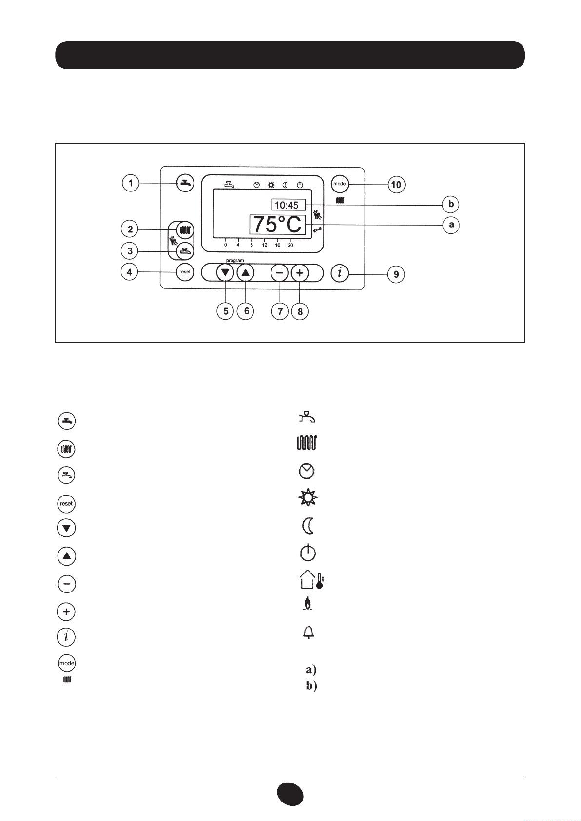
3) Follow the directions given below regarding the adjustments to be made at the boiler control panel.
Figure 1
020503_1100
IMPORTANT: The instructions contained in this manual relating to the operation of the hot water circuit
are relevant only if the appliance is actually connected to a hot water system.
KEYS DISPLAY SYMBOLS
Hot water on/off key
Central heating water temperature setting key
Hot water temperature setting key
Operation in hot water mode
Operation in central heating mode
Operation in automatic mode
Operation in manual mode at the maximum
Reset key
Program access and scroll keys
Program access and scroll key
Parameter setting key (decrease value)
Parameter setting key (increase value)
Data display reset key
temperature set
Operation in manual mode at minimum temperature
Standby (off)
Outdoor temperature
Flame present (on)
Resettable alarm warning
Central heating mode setting key
MAIN display
SECONDARY display
926.772.1 - GB/IEINSTRUCTIONS PERTAINING TO THE USER
4
Page 5
3.1 DESCRIPTION OF KEYS
(2) This key can be pressed to set the central heating water output temperature as described in point
3-3.
(3) This key can be pressed to set the hot water temperature as described in point 3-4.
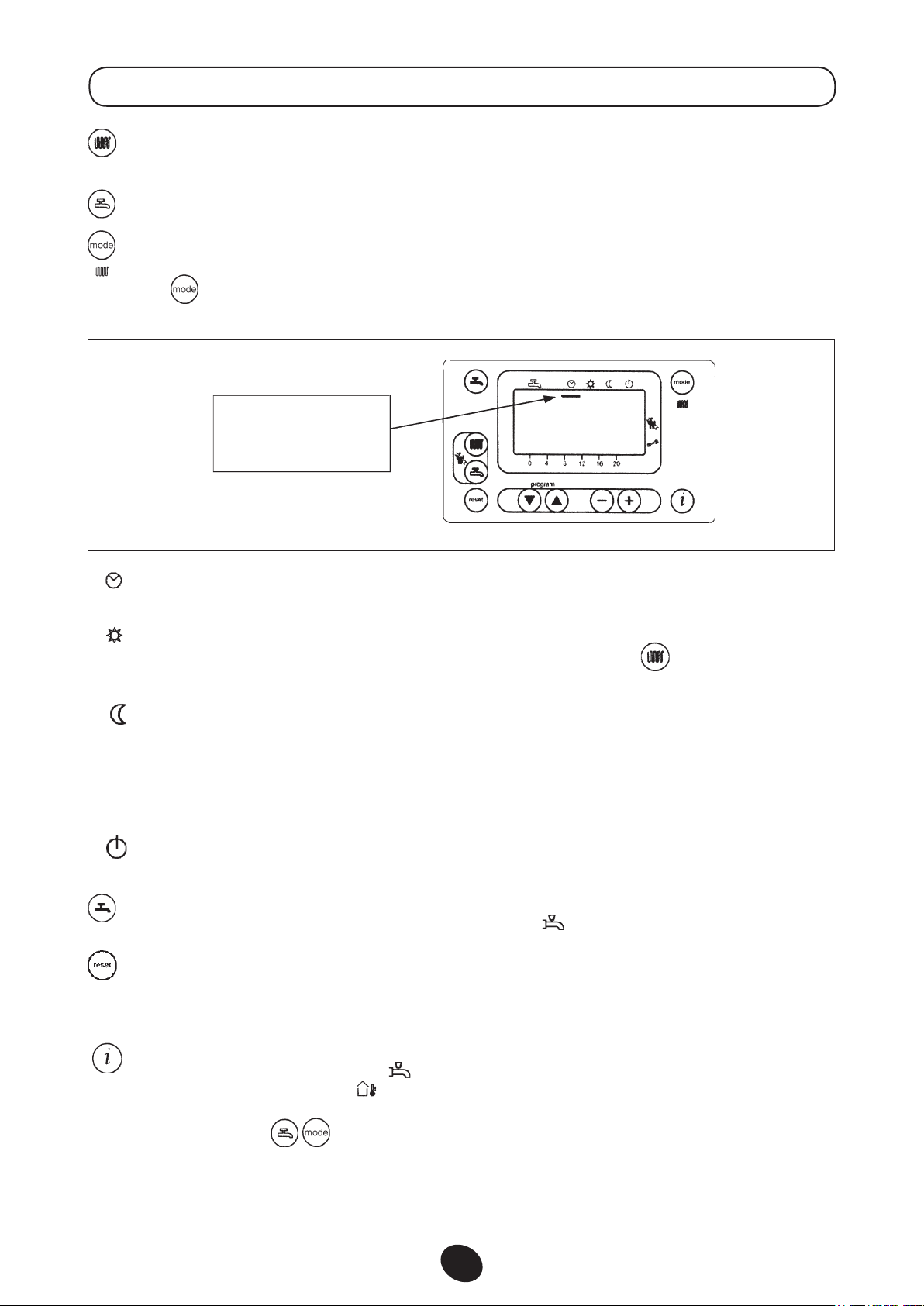
(10) Central heating mode operating key
The key can be pressed to activate four boiler central heating operating modes; these modes are
identied by a black cursor line underneath the relative symbol on the display, and are as follows:
Dash
“Automatic mode”
active
Figure 2
020503_0800
a) Automatic operation. Operation of the boiler is controlled by the timed program as described in point
3-5.1 “Daily timed program for operation of the central heating system”;
b) Manual operation at the maximum temperature set. The boiler comes into operation regardless of
the timed program set. The operating temperature is that set using the key (point 3-3: “Setting
the maximum central heating temperature”);
c) Manual operation at minimum temperature. The operating temperature is that set in point 3-6:
“setting the minimum central heating temperature”.
The manual transition from positions a) and b) to position c) involves shut-down of the burner and
disconnection of the pump after the post-circulation delay interval (the factory setting for this parameter
is 3 minutes).
d) standby. The boiler does not work in central heating mode, although the frost protection function is
still enabled.
(1) Hot water on/off key: Press this key to activate or inhibit this function, which is identied by the
appearance on the display of two black dashes under the symbol.
(4) Reset key. In case of a fault, referred to in point 3-7 “Faults and resetting the boiler”, the boiler
can be restarted by pressing this key for at least two seconds.
If this key is pressed with no fault present, the display will show the message “E153”, and the same
key has to be pressed again (for at least two seconds) to restart the boiler.
(9) Data key. This key can be pressed repeatedly to display the following information:
- Temperature (°C) of the hot water ( );
- outdoor temperature (°C) ( ); only provided with the outdoor temperature sensor probe
connected.
Press either of the keys to return to the main menu.
5
926.772.1 - GB/IEINSTRUCTIONS PERTAINING TO THE USER
Page 6
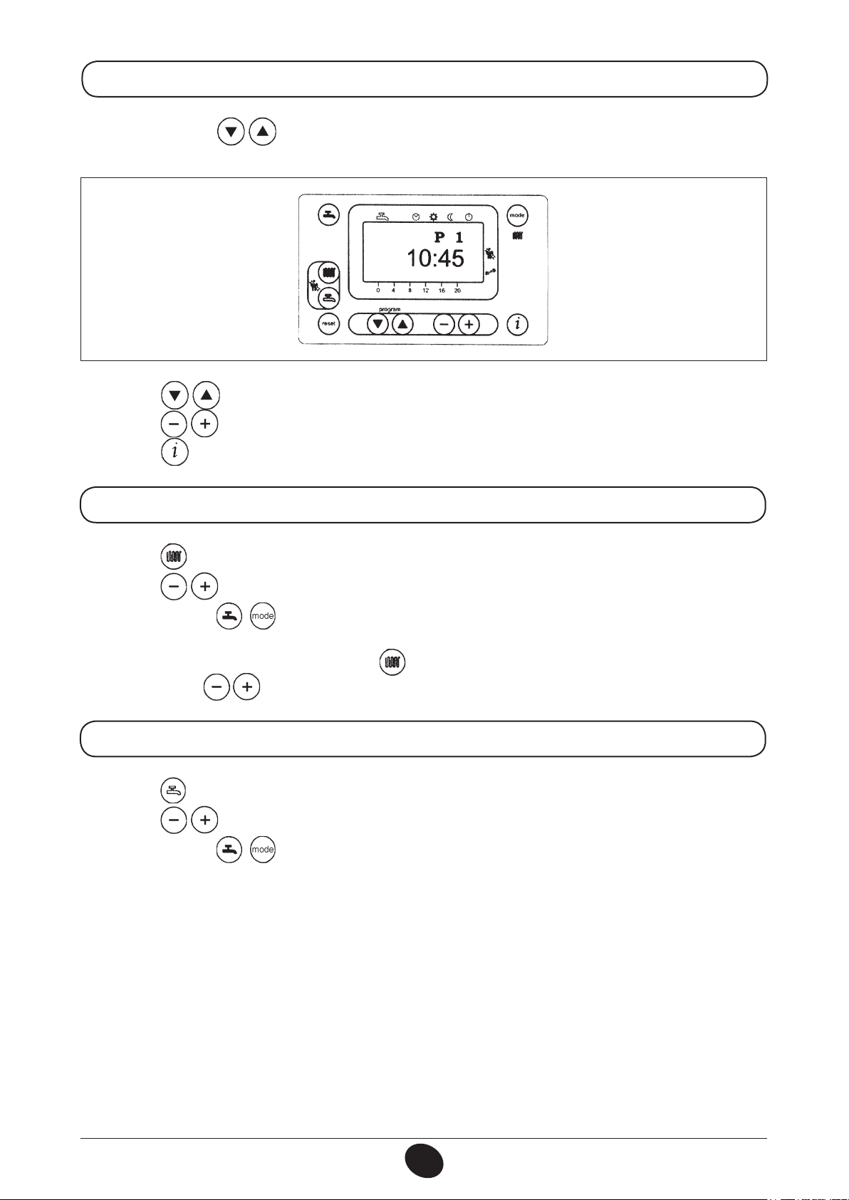
3.2 SETTING THE TIME
a) Press either of the keys to access the programming function;
the display will show the letter P followed by a number (program line);
Figure 3
b) Press the keys until the display shows P1, referring to the time to be set;
c) Press the keys to set the time; on the display, the letter P will start to ash;
d) Press the key to save and exit the programming function;
020503_0700
3.3 SETTING THE MAXIMUM CENTRAL HEATING TEMPERATURE
- Press the key (2-gure 1) to set the central heating water temperature;
- Press the keys to set the temperature required;
- Press either of the keys (1 or 10 - gure 1) to save and return to the main menu.
N.B – With the outdoor sensor connected, the key (2 - gure 1) can be used to shift the central heating
curve. Press the keys to decrease or increase the room temperature in the premises to be heated.
3.4 SETTING THE MAXIMUM HOT WATER TEMPERATURE
- Press the key (3-gure 1) to set the maximum hot water temperature;
- Press the keys to set the temperature required;
- Press either of the keys (1 or 10 - gure 1) to save and return to the main menu.
6
926.772.1 - GB/IEINSTRUCTIONS PERTAINING TO THE USER
Page 7
3.5 SETTING THE DAILY PROGRAM FOR OPERATION IN CENTRAL HEATING AND DOMESTIC HOT WATER MODES
3.5.1 Setting the daily times for central heating mode operation
- Press either of the keys to access the programming function;
a) Press these keys until the display shows P11, referring to the program start time;
b) Press the keys to set the time;
- Press the key; the display will show P12, referring to the program end time;
- Repeat the operations described in points a and b until the third and last cycle is reached (program line
P16);
- Press the key to save and exit from the programming function.
3.5.2 Setting the daily times for domestic hot water mode operation
- As supplied by the factory the appliance is set up with the hot water function always enabled and the do-
mestic hot water programming function disabled.
The instructions for enabling this program are given in chapter 17, which is addressed specically to installers
(parameter H91).
If the program is enabled program lines from 31 to 36 must be set up as described in heading 3-5.1.
3.6 SETTING THE MINIMUM CENTRAL HEATING TEMPERATURE
- Press either of the keys to access the programming function;
- Press these keys until the display shows p5, referring to the temperature to be set;
- Press the keys to set the temperature required.
This operating mode is enabled when minimum temperature central heating mode “ ” is activated or when
the daily central heating program does not require heat.
N.B – With the outdoor sensor connected, parameter P5 can be used to set the minimum room temperature in the premises to be heated (night setback).
7
926.772.1 - GB/IEINSTRUCTIONS PERTAINING TO THE USER
Page 8
3.7 TABLE FOR USER-SETTABLE PARAMETERS
Parameter
N.
P1 Time of day setting ———- 0…23:59
P5 Minimum central heating temperature setting (°C) 25 25..80
P11 Start of rst daily period of automatic central heating 6:00 00:00…24:00
P12 End of rst daily period of automatic central heating 22:00 00:00…24:00
P13 Start of second daily period of automatic central heating 0:00 00:00…24:00
P14 End of second daily period of automatic central heating 0:00 00:00…24:00
P15 Start of third daily period of automatic heating 0:00 00:00…24:00
P16 End of third daily period of automatic central heating 0:00 00:00…24:00
P31 Start of rst daily period of hot water production (*) 0:00 00:00…24:00
P32 End of rst daily period of hot water production (*) 24:00 00:00…24:00
P33 Start of second daily period of hot water production (*) 0:00 00:00…24:00
P34 End of second daily period of hot water production (*) 0:00 00:00…24:00
P35 Start of third daily period of hot water production (*) 0:00 00:00…24:00
P36 End of third daily period of hot water production (*) 0:00 00:00…24:00
P45
Parameter description
Reset of daily central heating and domestic hot water production programs (factory
settings). Press the - + keys together for about 3 seconds; the number 1 appears on the
display. Conrm by pressing either of the keys
Factory
setting
0 0...1
Range
Note: Parameters from P31 to P36 can be displayed only if the domestic hot water program has been enabled
as described in chapter 17 for the attention of the installer (parameter H91).
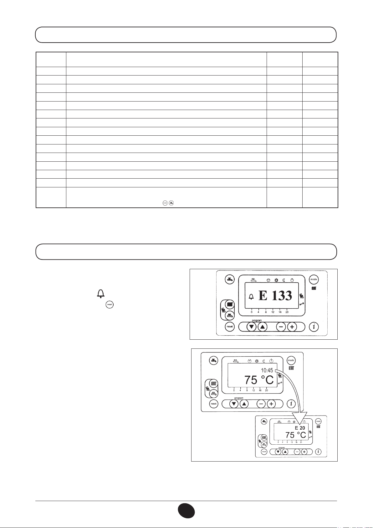
3.8 FAULT WARNINGS AND RESETTING THE BOILER
If a fault occurs, a ashing warning code appears
on the display.
The fault warnings appear on the main display (gure
1 a) together with the symbol (Figure 4).
To reset, press the reset button for at least two
seconds.
Fault warnings appear on the secondary display
(gure 1 b) alternating with the time, both of them
ashing (gure 4.1). It is not possible to reset malfunction warnings which appear on the secondary
display as the cause of the alarm has rst to be
removed.
020503_0500
Figure 4
0509_0201
8
Figure 4.1
926.772.1 - GB/IEINSTRUCTIONS PERTAINING TO THE USER
Page 9
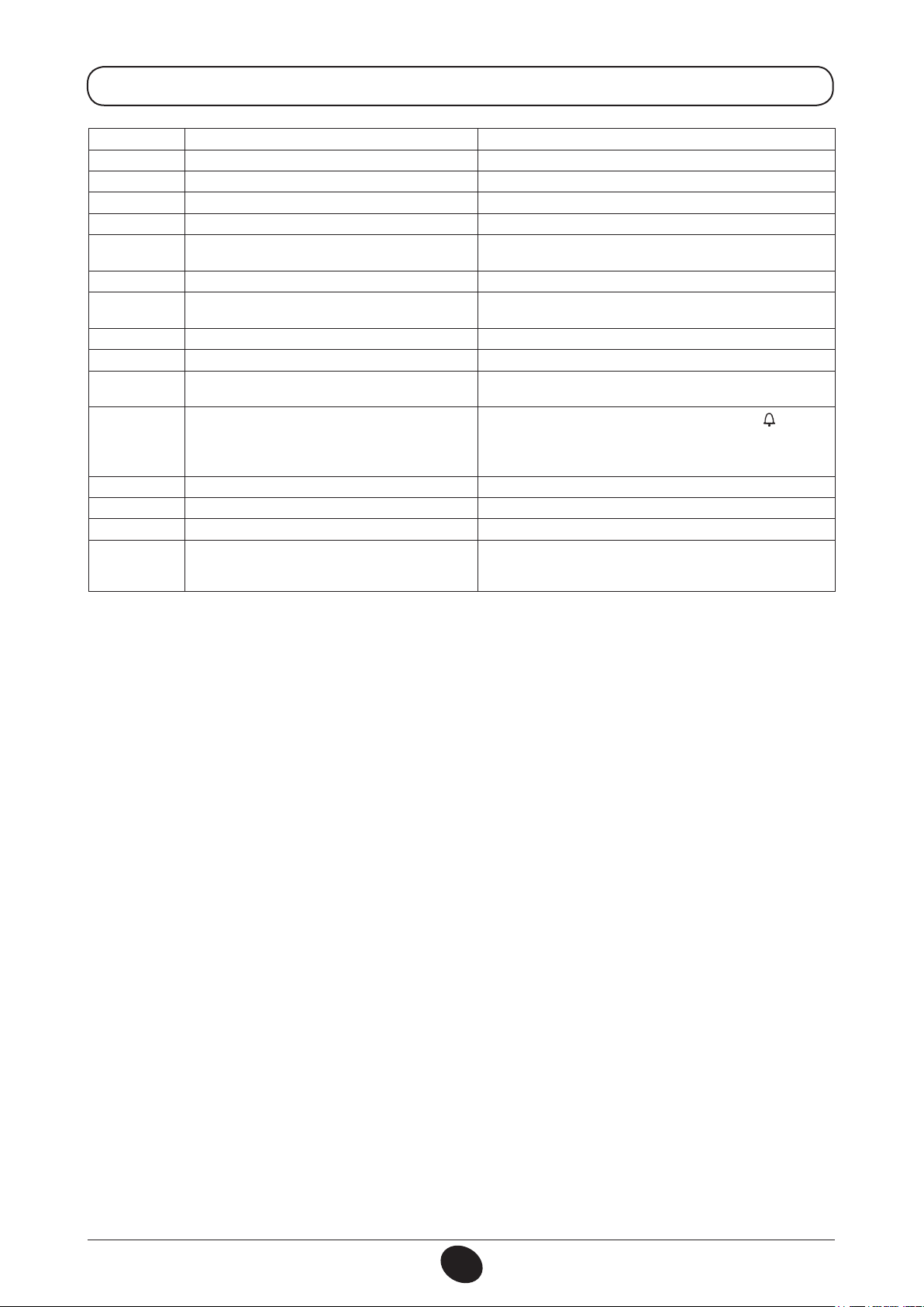
3.9 FAULT WARNINGS TABLE
Fault code Fault description action required
E10 outdoor temperature probe sensor failure call the authorised service centre.
E20 ntc output sensor failure call the authorised service centre
E40 NTC return heating probe faulty call the authorised service centre
E50 domestic hot water ntc sensor failure call the authorised service centre
E110
E111 Delivery temperature higher than 95°C If this fault persists, call the authorised service centre
E128
E129 Minimum fan speed limit is hurt Call an authorised service centre.
E132 oor thermostat tripped call the authorised service centre
E133 no gas
E151 boiler circuit board error
E153 the reset key has been pressed inappropriately press the key again (about 2 seconds)
E154
E160 fan speed threshold not reached call the authorised service centre.
E164 no hydraulic pressure switch enabling signal
Safety or fumes thermostat or heating return
temperature probe tripped
Loss of ame during operation (the ionization current
has fallen below the limit)
No circulation or reverse flow call the authorised service centre
press the reset key (for about 2 seconds: if this device is triggered
repeatedly, call the authorised service centre)
Call an authorised service centre.
press the reset key (for about 2 seconds); if the fault persists,
call the authorised service centre)
Press the reset button if the display presents the ( ) symbol,
otherwise switch off the boiler at the mains and switch it on again
after 10 seconds. If the fault persists, call an authorised service
centre. Check the position of the ignition electrodes (chapter 17).
check that the system is at the rated pressure. (refer to the
section on lling the system). if the fault persists, call the
authorised service centre.
All the faults are displayed in order of importance; if several faults occur simultaneously, the rst to be displayed is the one with highest priority. After the cause of the rst fault has been removed, the second one will
be displayed, and so on.
If any given fault occurs frequently, contact the authorised Service Centre.
9
926.772.1 - GB/IEINSTRUCTIONS PERTAINING TO THE USER
Page 10

4. FILLING THE BOILER
Important: Regularly check that the pressure displayed by the pressure gauge is between 1 to 4 bar, with the
boiler not operating.
In case the pressure is lower open the boiler lling tap.
We recommend you open the tap very slowly in order to let off the air.
In case pressure drops occur frequently have the boiler checked by a Qualied Service Engineer.
5. TURNING OFF THE BOILER
To shut down the boiler switch off the electrical supply to the appliance.
6. PROLONGED STANDSTILL OF THE SYSTEM. FROST PROTECTION
We recommend you avoid draining the whole system as raw water makeup will lead to harmful limestone
deposits inside the boiler and on the heating elements.
In case the boiler is not operated during wintertime and is therefore exposed to danger of frost we suggest you
add some specic-purpose anti-freeze to the water contained in the system (e.g.: propylene glycole coupled
with corrosion and scaling inhibitors).
The electronic management of the boilers includes a ‘frost protection’ function which operates the burner to
reach a heating ow temperature of 30° C when the system heating ow temperature drops below 5°C.
The frost protection function is enabled if:
* electrical supply to the boiler is on;
* the gas service cock is open;
* the system pressure is as required;
* the boiler is not isolated.
7. SERVICING INSTRUCTIONS AND GAS CHANGE
To maintain efcient and safe operation of your boiler have it checked by a Qualied Service Engineer at the
end of every heating season. Careful servicing will ensure economical operation of the system.
Do not clean the outer casing of the appliance with abrasive, aggressive and/or easily ammable cleaners
(i.e.: gasoline, alcohol, and so on). Always isolate the electrical supply to the appliance before cleaning it (see
section 5 Turning off the boiler).
These boilers are produced for natural gas and can be converted to work with LPG (G 31).
Any gas change must be effected by a Qualified Service Engineer.
10
926.772.1 - GB/IEINSTRUCTIONS PERTAINING TO THE USER
Page 11

8. GENERAL INFORMATION
The following remarks and instructions are addressed to Service Engineers to help them carry out a faultless
installation. Instructions regarding lighting and operation of the boiler are contained in the ‘Instructions pertaining to the user’ section.
Note that installation, maintenance and operation of the gas appliances must be performed exclusively by
qualied personnel in compliance with current standards.
Please note the following:
* This boiler can be connected to any type of double- or single feeding pipe convector plates, radiators,
thermoconvectors. Design the system sections as usual though taking into account the available output /
pump head performances.
* Do not leave any packaging components (plastic bags, polystyrene, etc.) within children’s reach as they are
a potential source of danger.
* Initial lighting of the boiler must be effected by a Qualied Service Engineer.
Failure to observe the above will render the warranty null and void.
9. INSTRUCTIONS PRIOR TO INSTALLATION
This boiler is designed to heat water at a lower than boiling temperature at atmospheric pressure. The boiler
must be connected to a central heating system and, on models with this option, to a domestic hot water supply
system in compliance with its performances and output criteria.
IMPORTANT! The gas boiler is supplied without the following components which must be provided exclusively
by qualied personnel:
• Expansion vessel;
• Pressure relief valve;
• Circulating pump;
• Boiler lling tap.
Before connecting the boiler ensure the following operations have been completed:
a) Check that the boiler is t for operation with the type of gas available. For more details see the notice on
the packaging and the label on the appliance itself.
b) Check that the ue terminal draft is appropriate; that the terminal is not obstructed and that no other applian-
ce exhaust gases are expelled through the same ue duct, unless the ue is especially designed to collect
the exhaust gas coming from more than one appliance, in conformity with the standards and regulations in
force.
c) Check that, in case the ue has been connected to pre-existing ue ducts, thorough cleaning has been
carried out in that residual combustion products may be created during operation of the boiler and obstruct
the ue duct.
To ensure correct operation of the appliance and avoid invalidating the warranty, observe the following
precautions:
1. Hot water circuit:
If the water hardness is greater than 20 °F (1 °F = 10 mg calcium carbonate per litre of water) a
polyphosphate or comparable treatment system responding to current regulations must be used.
2. Heating circuit
2.1. New system
Before proceeding with installation of the boiler, the system must be cleaned and ushed out thoroughly
to eliminate residual thread-cutting swarf, solder and solvents if any, using suitable proprietary products.
INSTRUCTIONS PERTAINING TO THE INSTALLER 926.772.1 - GB/IE
11
Page 12

To avoid damaging metal, plastic and rubber parts, use only neutral cleaners, i.e. non-acid and non
alkaline. The recommended products for cleaning are:
SENTINEL X300 or X400 and FERNOX heating circuit restore. Please ensure to use this product
proceeding strictly in accordance with the manufacturers instructions. Finally ll the system with the
correct strength of central heating inhibitor.
2.2. Existing system
Before proceeding with installation of the boiler, the system must be cleaned and ushed out to remove
sludge and contaminants, using suitable proprietary products as described in section 2.1.
To avoid damaging metal, plastic and rubber parts, use only neutral cleaners, i.e. non-acid and non-
alkaline such us SENTINEL X100 and FERNOX heating circuit protective. To use this product proceeding
strictly in accordance with the maker’s directions.
Remember that the presence of foreign matter in the heating system can adversely affect the operation
of the boiler (e.g. overheating and noisy operation of the heat exchanger). Dose with inhibitor.
Failure to observe the above will render the guarantee null and void.
10. BOILER INSTALLATION
Decide upon the boiler location, then tape the template on the wall.
Connect the pipework to the gas and water inlets prearranged on the template lower bar.
If you are either installing the boiler on a pre-existing system or replacing it, we suggest you also t strainers
on the system return pipework to the boiler to collect the deposits and scaling which may remain and be
circulated in the system after the initial lling.
When the boiler is xed on the template connect the ue and air ducts (ttings supplied by the manufacturer)
according to the instructions given in the following relevant sections.
Connect the condensate outlet to the siphon supplied with the boiler. Connect the siphon to a drain, making
sure there is a continuous slope. Horizontal sections must be avoided.
0506_0806
Figure 5
DRILL HOLES WITH A Ø12 BIT, FIT THE MASONRY
PLUGS AND THE SCREWS PROVIDED
FLUE AXIS
N.B. INCLUDE CONDENSATE DRAIN POINT
BOILER HEIGHT 950
BOILER WIDTH 600
gas inlet to the boiler
heating ow
heating return
condensation drain
0602_0701/CG_1469/1
MR: G 1” heating ow
GAS: G 3/4” gas inlet to the boiler
RR: G 1” heating return
SC: condensation drain 22 mm
INSTRUCTIONS PERTAINING TO THE INSTALLER 926.772.1 - GB/IE
12
Page 13

Figure 6
11. BOILER SIZE
0310_0103
12. INSTALLATION OF FLUE AND AIR DUCTS
We guarantee ease and exibility of instal lation for the boiler thanks to the ttings and xtures supplied (described below).
The boiler is especially designed for connection to an exhaust ue / air ducting, with either concentric, vertical
or horizontal terminal.
Where exhaust and intake flues not
supplied by POTTERTON GOLD HIGH
OUTPUT have been installed, these
must be certied for the type of use
and must have a maximum pressure
drop of 100 Pa for the complete flue
installation.
C
33
C
13
Figure 7
INSTRUCTIONS PERTAINING TO THE INSTALLER 926.772.1 - GB/IE
13
0709_1001
Page 14

HORIZONTAL CONCENTRIC FLUES
Boiler Flue Size
WH46 Ø80/125 9 m 8 m 7 m 6 m
WH65 Ø80/125 9 m 8 m 7 m 6 m
VERTICAL CONCENTRIC FLUES
Boiler Flue Size
WH46 Ø80/125 9 m 8 m 7 m 6 m
WH65 Ø80/125 9 m 8 m 7 m 6 m
Boiler Flue Size
WH46 Ø80 59,5 m 59 m 58,5 m 58 m
WH65 Ø80 59,5 m 59 m 58,5 m 58 m
1 2 3 4
1 2 3 4
CONVENTIONAL FLUE
1 2 3 4
Number of Bends 90°
Number of Bends 90°
Number of Bends 90°
Concentric flue
This type of duct allows to emit exhaust gases and to draw combustion air from outside the building.
The 87° coaxial bend allows to connect the boiler to a ue-air duct in any direction as it can rotate through
360°.
If the ue outlet is placed outside, the ue-air ducting must protrude at least 18mm out of the wall to allow
alluminium weathering tile to be tted and sealed to avoid water leakages. If the terminal is below 2m then a
terminal gaurd is required.
Ensure a minimum downward slope of 3° towards the boiler.
A 87° bend reduces the total ue length by 1 metre.
A 45° bend reduces the total ue length by 0.5 metre.
990519_0400
Concentric outlet
Figure 8
INSTRUCTIONS PERTAINING TO THE INSTALLER 926.772.1 - GB/IE
14
Page 15

12.1 HORIZONTAL FLUE TERMINAL
L = refer to table
Ø 80/125
INSTALLATION OPTIONS
0602_0702
12.2 VERTICAL FLUE TERMINAL
Ø 80/125 mm
INSTALLATION OPTIONS
This type of installation can be carried out both on a at or pitched roof by tting a terminal, an appropriate
weathering tile and sleeve, (supplementary ttings supplied as options).
0310_0107
L = refer also the table
L max = 10 m
L max = 10 m L max = 9 mL max = 8 m
12.5 FAN RPM UPDATING DEPENDING ON FLUE LENGTH (e.g. figure 7)
To ensure the correct rated heat output to the maximum and minimum heat input, it is necessary to update
the speed (rpm) of the fan, it depends on the length of the ue (par. 12), in accordance with the installation of
ue and air pipes as indicated in the tables below. The factory-set value is referred to the minimum length of
ue pipe (0÷4 m for concentric, 0÷20 m for twin). To carry such updating, changing the speed of the fan (rpm)
at the maximum and minimum heat input, refer to par. 16.
WH 46
CONCENTRIC PIPE Ø 80/125
(C13-C33-C43)
Parametres
Pipes length (m)
(*) 0 - 4
5 - 10
H536-H613
Max heat output (rpm) Min heat output (rpm)
5500 1900
5900 2100
(*) Default setting parameters
INSTRUCTIONS PERTAINING TO THE INSTALLER 926.772.1 - GB/IE
Parametres
H612
(*) Default setting parameters
WH 65
Pipes length (m)
(*) 0 - 4
5 - 10
CONCENTRIC PIPE Ø 80/125
(C13-C33-C43)
Parametres
H536-H613
Max heat output (rpm) Min heat output (rpm)
Parametres
H612
6000 1850
6500 2100
15
Page 16

13. HYDRAULIC DIAGRAM
Applications and Installation Details
13.1 HYDRAULIC SYSTEM 1
(Pumped heating circuits with remote control QAA73 or Room Thermostat, including hot-water tank, without
and with primary loop)
(*)
(*) optional extra
Figure 9a
(*)
without low loss header
(*)
(*)
(*)
0602_0704/CG1782
(*) optional extra
(*)
with low loss header and primary loop
Figure 9b
INSTRUCTIONS PERTAINING TO THE INSTALLER 926.772.1 - GB/IE
(*)
(*)
16
0602_0703/CG1756
Page 17

• TS: Tank Sensor (QAZ36)*
• B3: Room Control Module (QAA73)*
• B1: Room Thermostat
• B9: Outdoor Temperature Sensor (QAC34)*
• P1: Heating Pump
• PDHW: Hot Water pump
• PLP: Primary Pump (only for gure 9b)
(*) Available Optional Extra
• Pumps (Not Supplied)
• Isolating Valve (Not Supplied)
• Installer Wiring --------------
• Hot Water Cylinder (Not Supplied)
• Low Loss Header (Not Supplied)
• Non return valve (Not supplied)
Applications (pumps, sensor, remote control ...) have to be connected to terminal as follows (see also section 14):
WITH QAA73
REMOTE CONTROL
WITH
ROOM THERMOSTAT
APPLICATION TERMINAL BOARD TERMINAL BOARD
PRIMARY PUMP PLP (only for gure 9b) M1: A – B M1: A – B
DHW PUMP PDHW M3: 13 – 14 M3: 13 – 14
HEATING PUMP P1 M3: 11 – 12 M3: 11 – 12
DHW SENSOR TS M2: 7 – 8 M2: 7 – 8
REMOTE CONTROL QAA73 M2: 1 – 2 NO
ROOM THERMOSTAT M2: 3 – 4 OPEN M2: 3 – 4
Parameter changes requires (see also section 16):
PCB
PARAMETER
Description Setting Parameter
H552 Hydraulic system H552 = 2
H553 KongHKS H553 = 21
H615 KongAusgang H615 = 9
H632 Wanfo Q8 H632 = 00001100
INSTRUCTIONS PERTAINING TO THE INSTALLER 926.772.1 - GB/IE
17
Page 18

13.2 HYDRAULIC SYSTEM 2
(Pumped heating circuits with Room Thermostat and compensated circuit with remote control QAA73, including hot-water tank, with primary loop)
• TS:Tank Sensor (QAZ36)*
• B3: Room Control Module (QAA73)*
• B1: Room Thermostat
• B9: Temperature Sensor (QAC34)*
• Zone Controller (Clip-in AGU2.500)*
• FS: Flow Sensor (QAD36: supplied with AGU2.500)*
• P1: Heating Pump
• P DHW: Hot Water pump
• PLP: Primary Pump
• 3WV: 3-way Valve (power open / power close)
(*) Available Optional Extra
• Pumps (Not Supplied)
• Isolating Valve (Not Supplied)
• Installer Wiring --------------
• Hot Water Cylinder (Not Supplied)
• Low Loss Header (Not Supplied)
• Non Return Valve (Not supplied)
*
0602_0705/CG1759
*
*
HEATING CIRCUIT
COSTANT TEMP.
AGU 2.500*
HEATING CIRCUIT
VARIABLE TEMP.
*
Figure 10
INSTRUCTIONS PERTAINING TO THE INSTALLER 926.772.1 - GB/IE
18
Page 19

Applications (pumps, sensor, remote control ...) have to be connected to terminal as follows (see also section 14):
APPLICATION TERMINAL BOARD
PRIMARY PUMP PLP M1: A – B
DHW PUMP PDHW M3: 13 – 14
HEATING PUMP P1 M3: 11 – 12
DHW SENSOR TS M2: 7 – 8
REMOTE CONTROL QAA73 (LOW TEMPERATURE) M2: 1 – 2
ROOM THERMOSTAT M2: 3 – 4
HEATING PUMP P2 CLIP IN AGU 2.500
3 WAY VALVE CLIP IN AGU 2.500
FLOW SENSOR CLIP IN AGU 2.500
Parameter changes requires (see also section 16):
PCB
PARAMETER
Description Setting Parameter
H552 Hydraulic system H552 = 50
H553 KongHKS H553 = 12
H615 KongAusgang H615 = 9
H632 Wanfo Q8 H632 = 00001111
13.3 HEAT EXCHANGER PRESSURE DROP
Hydraulic Resistance and Water Flow Rates
Boiler
WH46 70,61 0,98 31,38 0,72 11,77 0,54 10,79 0,36
WH65 56,88 1,41 34,32 1,04 20,59 0,78 11,77 0,52
Boiler
WH46 0,28
WH65 0,35
11°C ∆T 15°C ∆T 20°C ∆T 30°C ∆T
kPa Lit/sec kPa Lit/sec kPa Lit/sec kPa Lit/sec
Minimum Water Flow Rates
Lit/sec
INSTRUCTIONS PERTAINING TO THE INSTALLER 926.772.1 - GB/IE
19
Page 20

14. CONNECTING THE MAINS SUPPLY
Electrical safety of the appliance is only guaranteed by correct earthing, in compliance with the applicable
standards and regulations.
Connect the boiler to a 230V earthed power supply by means of the three-pin cable supplied ensure that the
polarity is correct.
Use a double-pole switch isolator with a contact separation of at least 3mm in both poles.
In case you replace the power supply cable t a HAR H05 VV-F’ 3x0.75mm2 cable with an 8mm diameter
maximum outer sheath.
The fuse, a fast-acting type rated 2A, is incorporated into the power supply terminals (remove the black fuse
holder to enable inspection and/or replacement).
IMPORTANT: Check that the overall current drawn by accessories connected to the appliance is less than 1
amp. If the value is greater, a relay must be wired between the boiler control circuit board and the accessories
drawing the higher current.
Terminal board M1
Terminal board M2
Cover
020523_0400
Figure 11
Cover
INSTRUCTIONS PERTAINING TO THE INSTALLER 926.772.1 - GB/IE
20
Page 21

14.1 CONNECTING THE PUMPS
Turn the control box downward to access terminal boards M1 and M3 used for the electrical connections by
removing the protective covers (see gure 12).
Terminals M1 a – b: connection of the primary loop pump for the heating system (PLP)
Check the correct size and rating of the pump by referring to its hydraulic resistance table.
Terminals M3 11 – 12: connection for heating pump (P1)
Terminals M3 13 – 14: connection for hot water tank pump (PDHW)
The electrical specications of the pump must be as follows:
230 V AC; 50 Hz; 1 A max; cos f > 0.8.
If the specications of the installed pump are different, a relay must be wired between the boiler control circuit
board and the pump.
It is advisable not to adopt any electrical connection other than those described.
Connect earth to earth strip
Figure 12
CG_1763 / 0906_2205
INSTRUCTIONS PERTAINING TO THE INSTALLER 926.772.1 - GB/IE
21
Page 22

14.2 CONNECTING THE HOT WATER TANK SENSOR
Remove the resistor from terminals 9-10 of terminal strip M2 (gure 13), and connect the hot water priority
NTC sensor, which is supplied as an accessory.
The sensing element of the NTC device must be located in the recess provided on the storage tank (gure 13).
The temperature and on-off programming of the domestic hot water supply are selected directly from the
boiler control panel, as described in this manual under the user instruction headings.
0602_0707/CG1764
SAFETY
CONTACT
ROOM THERMOSTAT
Figure 13
INSTRUCTIONS PERTAINING TO THE INSTALLER 926.772.1 - GB/IE
22
Page 23

14.3 DESCRIPTION OF THE ELECTRICAL CONNECTIONS TO THE BOILER
Turn the control box downward to access terminal board M2 used for the electrical connections by removing
the protective cover (see gure 13).
Terminals 1-2: connection of SIEMENS model QAA73 room temperature regulator supplied as optional extra.
Connection polarity is irrelevant.
The link tted across the “TA” terminals 3-4 must be removed.
Read the instructions supplied with this accessory for correct installation and programming procedures.
Terminals 3-4: “TA” room temperature thermostat connection. Thermostats with integral accelerator resistor
must not be used. Check that there is no voltage across the ends of the two thermostat connection wires.
Terminals 5-6: external safety contact (low voltage).
Terminals 7-8: connection of SIEMENS model QAC34 outdoor temperature sensor supplied as optional extra.
Read the instructions supplied with this accessory for correct installation procedures.
Terminals 9-10: connection of hot water temperature sensor supplied as optional extra for connecting heating-only boilers to an external water heater.
CLIP-IN AGU 2.511
Terminals 3-4 L-N OUT: connection to signal lamp (230 V - 0,5 A max) for lockout alarm.
Terminals 5-6 L-N OUT: connection to signal lamp (230 V - 0,5 A max) for run mode.
For low voltage signal lamp remove the internal wiring and feed with an external low voltage power supply.
(OPTIONAL EXTRA)
0602_0708/CG1765
Figure 14
INSTRUCTIONS PERTAINING TO THE INSTALLER 926.772.1 - GB/IE
23
Page 24

14.4 CONNECTING THE QAA73 TEMPERATURE REGULATOR
The SIEMENS model QAA73 room temperature regulator, if required (optional extra) must be connected to
terminals 1-2 of terminal board M2 in gure 13.
The link across terminals 3-4, provided for connection of a room temperature thermostat, must be removed.
The settings of the domestic hot water temperature and domestic hot water production schedule must be
made using this device.
The timed program of the central heating circuit must be set on the QAA73 if there is a single zone, or in relation
to the zone controlled by the QAA73 device.
The timed program for the central heating circuit of the other zones can be set directly on the boiler control
panel.
See the instructions provided with the QAA73 room temperature regulator for the user parameter programming
procedure.
IMPORTANT: For systems divided into zones, parameter 80 “HC2 curve”, which can be set on the QAA73
temperature regulator, must be set as _ _ . _ “not active”.
QAA73: parameters which can be set by the installation engineer (service)
By pressing the two PROG buttons together for at least three seconds it is possible to access the list of parameters that the installer can display and/or set.
Press either of these buttons to change the parameter to display or change.
Press the [+] or [-] key to change the value displayed.
Press either of the PROG buttons again to save the change.
Press the information button (i) to quit programming.
Here follows a list of the most commonly used parameters:
Line no.
Parameter
70
HC1 curve
Selection of central heating circuit temperature curve “kt”
72
HC1 max. output
Central heating system maximum output temperature
74
Type of building
75
Room compensation
Activation/deactivation of the inuence of the room temperature. If it is deactivated, the outdoor
temperature sensor must be installed.
77
Automatic adaptation of the temperature curve “kt” in relation to the room temperature.
78
Opt Start Max
Maximum time the boiler is switched on ahead of the timed program to optimise the temperature
in the premises.
79
Opt Stop Max
Maximum time the boiler is switched off ahead of the timed program to optimise the temperature
in the premises.
80
HC2 curve
90
DHW Red Setp
Minimum temperature of the domestic hot water
91
DHW program
Selection of the type of timed program for domestic hot water.
24 h/day = always on
PROG HC-1h = as HC1 central heating program less one hour
PROG HC = as central heating program
PROG DHW = specic domestic hot water program (see also program lines 30-36)
Range Default value
2.5…40 15
25…85 85
Light, Heavy Light
on HC1
on HC2
on HC1+HC2
nil
On - off On
0…360 min 0
0…360 min 0
2.5…40
—.- = not active
10 or 35…58 10
24 h/day
TSP HC-1h
TSP HC
TSP DHW
On HC1
—.-
24 h/day
- fault messages
In the event of fault, the display panel on the QAA73 shows the ashing symbol . Press the information key
( ) to display the error code and a description of the fault (see Fault warning tables on paragraph 3.9).
INSTRUCTIONS PERTAINING TO THE INSTALLER 926.772.1 - GB/IE
24
Page 25

14.5 CONNECTING THE OUTDOOR TEMPERATURE SENSOR
The SIEMENS model QAC34 outdoor temperature sensor (optional extra) for weather compensation must be
connected to terminals 7-8 of terminal board M2 in gure 13.
The procedures for setting the gradient of the temperature curve “kt” vary depending on the accessories
connected to the boiler.
a) Without QAA73 room temperature regulator:
The temperature curve “kt” must be selected by setting parameter H532 as described in section 16 “setting
the boiler parameters”.
See graph 2 for selecting the curve referred to a room temperature of 20°C.
The chosen curve can be shifted by pressing the (2), button (2) on the boiler control panel, and modifying
the value displayed by pressing the and keys. See graph 3 for curve selection. (The example show
in graph 3 refers to the curve Kt=15).
Increase the value displayed if the room temperature required is not reached inside the premises for central
heating.
020523_0600
TM = Flow temperature
Te = Composite outside temperature
Graph 2 Graph 3
Sth = Kt Curve
INSTRUCTIONS PERTAINING TO THE INSTALLER 926.772.1 - GB/IE
25
Page 26

b) With QAA73 room temperature regulator:
The temperature curve “kt” must be selected by setting parameter 70 “HC1 curve” of the QAA73 room temperature control device as described in section 14.4 “QAA73: parameters which can be set by the installation
engineer (service)”.
See graph 4 for selecting the curve referred to a room temperature of 20°C.
The curve is shifted automatically on the basis of the room temperature set using the QAA73 climate control.
If the system is divided into zones, the temperature curve “kt” relating to the part of the system not controlled by the QAA73 must be selected by setting parameter H532 as described in section 16 “setting the boiler
parameters”.
IMPORTANT: For systems divided into zones, parameter 80 “HC2 curve”, which can be set on the QAA73
room temperature regulator, must be set as _ _ . _ “not active” (see section 14.4).
010905_0100
TM = Flow temperature
Graph 4
Te = Composite outside temperature
c) With AGU2.500 for control of a low temperature system:
Refer to the instructions provided with the AGU2.500 accessories for connection and control of a low temperature zone.
INSTRUCTIONS PERTAINING TO THE INSTALLER 926.772.1 - GB/IE
26
Page 27

15. GAS VALVE ADJUSTMENT
Carry out the following ope rations in the given sequence:
1)
Calibration of the maximum heat output. Check that the CO2 measured on the ue, with the boiler operating
at the maximum heat output, is the same as that shown in table 1. Otherwise, turn the regulation screw (V) on
the gas valve. Turn the screw clockwise to reduce the concentration of CO2 and anticlockwise to increase it.
2) Calibration of reduced heat output. Check that the CO2 measured on the ue, with the boiler operating at the
minimum heat output, is the same as that shown in table 1. Otherwise, turn the offset regulation screw (K) on
the gas valve. Turn the screw clockwise to increase the concentration of CO2 and anticlockwise to reduce it.
0310_0114
Pi: Gas supply pressure connection point
P out: Gas pressure to burner connection point
P: Pressure connection point
for measurement of the OFFSET
Pl: Air signal input from fan
V: Gas ow adjuster screw max re
K: OFFSET adjuster screw min re
Figure 15
To simplify calibration of the gas valve, the “calibration function” can be set directly on the boiler control panel
by proceeding as follows:
1) Press the keys (2-3) together until the display shows the pointer “ ” alongside the and symbols
(about 6 seconds) (see g. 16).
2) Press the keys to set the fan speed at the minimum and maximum heat output (%PWM);
N.b - to set the minimum and maximum heat output quickly, press the keys respectively;
3) press either of the two keys to exit the function.
0307_2201
Figure 16
INSTRUCTIONS PERTAINING TO THE INSTALLER 926.772.1 - GB/IE
27
Page 28

IMPORTANT: in the case of conversion from natural gas to propane (LPG), the following operations must be
performed before calibrating the gas valve as illustrated previously:
• Turnadjusterscrew(V)onthegasvalvethroughthenumberofcompleterevolutionsspeciedintable3.
G20 - 2H - 20 mbar G31 - 3P - 37 mbar
CO2
max. heat output 8.7 % 10 %
CO2
min. heat output 8.4 % 9.8 %
Table 1
Gas consumption at 15 °C
1013 mbar
gas
G20 - 2H - 20 mbar
PCI (MJ/Kg) NET 34.02 34.02
Consumption at max. heat output (Kg/h) 4.91 7.08
Consumption at min. heat output (Kg/h) 1.58 2.11
Gas nozzle (mm) 8.5 ---
Table 2
Gas consumption at 15 °C
1013 mbar
gas G31 - 3P - 37 mbar
PCI (MJ/Kg) NET 46.34 46.34
Consumption at max. heat output (Kg/h) 3.60 5.20
Consumption at min. heat output (Kg/h) 1.16 1.55
Gas nozzle (mm) 8.5 ---
Table 2.1
WH 46 WH 65
WH 46 WH 65
Model Counter clockwise
turns of screw
WH 46 3
WH 65 4 3/
Table 3
(V)
4
INSTRUCTIONS PERTAINING TO THE INSTALLER 926.772.1 - GB/IE
28
Page 29

16. SETTING THE BOILER PARAMETERS
The boiler parameters may only be modied by professionally qualied staff proceeding as follows:
a) Press the , keys on the boiler’s front panel together for about 3 s until the parameter H90 appears on
the display;
b) Press the keys to select the parameter for modication;
c) Press the and keys to modify the parameter;
d) Press the key to exit the programming function.
The following are the parameters generally used:
N° parametro Description Factory setting
H90 Setting for domestic hot water reduced temperature (°C) 10
H91
H505
H507
H516 Automatic Summer / Winter switching temperature (°C). 20
H532 Selection of temperature curve of central heating circuit HC1 (see Graph 1) 15
H533 Selection of temperature curve of central heating circuit HC2 (see Graph 1) 15
H536 Maximum speed at maximum output in heating mode (rpm - maximum speed limitation)
H612 Setting value of required speed (rpm) at low-re
H536-H613 Setting value of required speed (rpm) at high-re heating / domestic hot water mode
H541-H610 PWM (%) setting: maximum output in heating / domestic hot water mode
H544 Pump post-circulation time in central heating mode (min) 10
H545 Burner operating pause time between two start-ups (s) 180
H552
H553
H615 Programmable function 9
H632
H641 Fan post-purge interval (s) 10
H657
D.H.W. (Domestic Hot Water) program
(0 = enabled; 1 = disabled)
Maximum temperature (°C) of the central heating circuit HC1 corresponding to:
- the main circuit in systems with just one zone;
- the circuit of the zone where the QAA73 temperature control device is installed in case of
systems with more than one high-temperature zone;
- the high temperature zone circuit in mixed systems and if the SIEMENS AGU2.500 accessory
is used.
Maximum temperature (°C) of the central heating circuit HC2 of a system with more than one
zone, corresponding to the circuit of the low-temperature zone if the SIEMENS AGU2.500
accessory is used.
Hydraulic system setting (see instructions provided with the SIEMENS AGU2.500 accessory).
H552 = 50 with AGU2.500
H552 = 80 with RVA 47
Conguration of heating circuits
H553 = 12 with AGU2.500
Conguration of system with low loss header P1
H632 = 00001111 with AGU2.500
H632 = 00001000 with storage tank without low loss header
The value of Bit could be 1 or 0.
Press the keys 5 and 6 to select the bit to modify (b0 is the bit on the right, b7 is the last bit
on the left).
To modify the Bit value press on the keys 7 and 8
Setpoint of autonomous ANTILEGIONELLA function
60...80 °C = setting temperature range
0 = function inactive
1
80
80
Refer to
paragraph 12.1
2
21
00001100
0
Table 4
If the electronic circuit board is replaced, make sure that the parameters set are those specic to the boiler
model, as indicated in the documentation available from the authorised Service Centre.
(*) For these parameters see section 13 (hydraulic system).
INSTRUCTIONS PERTAINING TO THE INSTALLER 926.772.1 - GB/IE
29
Page 30

17. CONTROL AND OPERATION DEVICES
The boiler has been designed in full compliance with European reference standards and in particular is equipped with the following
• Overheat thermostat
This thermostat interrupts the gas ow to the main burner in case the water contained in the circuit has ove-
rheated. Under these conditions the boiler locks out and can only repeat the ignition procedure by pressing
of the reset button on the boiler after the cause of the trip has been rectied.
It is forbidden to disable this safety device
• Boiler circuit circulation test
The boiler electronic management unit is tted with a “boiler circulation test” function which involves con-
tinuously checking the primary circuit delivery and return temperatures. In case of an irregular increase in
the delivery and return temperature or a temperature reversal, the boiler stops and signals the error on the
display (see error table).
• Flue thermostat
This device, positioned on the ue inside the boiler, interrupts the ow of gas to the burner if the temperature
exceeds 90 °C. After verifying the cause of the trip, press the reset button positioned on the thermostat
itself, then press the reset button on the boiler.
It is forbidden to disable this safety device
• Flame ionization detector
The ame sensing electrode guarantees safety of operation in case of gas failure or incomplete interlighting
of the main burner.
Under such conditions the boiler is locked out.
You must press the reset button on the boiler to restore the normal operating conditions.
• Supplementary pump overrun
After the burner has switched off due to a room thermostat intervention the preset pump overrun of the
pump lasts 10 minutes, when the boiler is in the central heating mode.
• Frost protection device
The boilers electronic management includes a “frost protection” function in the central heating system which
operates the burner to reach a heating ow temperature of 30°C when the system heating ow temperature
drops below 5 °C.
This function is enabled as long as the boiler is connected to the a.c. power supply gas supplies and the
pressure in the system is as specied.
• Pump-blocking prevention
In case there is no call for heat either from the central heating system or from the DHW system for 24 hours
on end the pump will automatically switch on for 10 seconds.
• Gas pressure switch
This device enables the main burner only to be switched on if the gas pressure is over 12 mbar.
• Hydraulic pressure sensor
This device enables the main burner only to be switched on if the system pressure is over 0.5 bar.
INSTRUCTIONS PERTAINING TO THE INSTALLER 926.772.1 - GB/IE
30
Page 31

18. POSITIONING OF THE IGNITION AND FLAME SENSING ELECTRODE
CT_0826 / 1003_1001
Figure 17
19. CHECK OF COMBUSTION PARAMETERS
To measure the performance of combustion products, the forced draught boiler models are equipped with two
test points on the tapered coupling specically designed for this purpose.
One of the two test points is connected to the exhaust ue duct to allow measurements of the combustion
products and efciency.
The second test point is connected to the comburant air inlet duct to check possible combustion products
circulation in case of coaxial ducts.
The exhaust ue duct test point allows measurements of the following:
• combustionproductstemperature;
• concentrationofoxygen(O2) or, alternatively, of carbon dioxide (CO2);
• concentrationofcarbonmonoxide(CO).
The comburant air temperature must be measured at the test point connected to the air inlet duct.
020429_0300
ue gas
combustion air
gasket
Figure 18
INSTRUCTIONS PERTAINING TO THE INSTALLER 926.772.1 - GB/IE
31
Page 32

20. ACTIVATING THE CHIMNEY-SWEEP FUNCTION
To facilitate measurement of the combustion efciency and improve the cleanliness of the production products,
the chimney sweep function can be activated by proceeding as described below:
1) Press the (2-3) together until the pointer “ ” appears on the display alongside the symbol (about 3
seconds but no more than 6 seconds). In these conditions, the boiler operates at the maximum heat output
set for central heating.
2) Press either of the buttons to exit the function.
020429_0200
Figure 19
21. ANNUAL SERVICE
To ensure the boiler operates at peak efciency, the following checks must be performed every year:
•Checkontheappearanceandtightnessofthegasandcombustioncircuitgaskets;
•Checkontheconditionandpositionoftheignitionandamesensingelectrodes(seesection18);
•Checkontheconditionoftheburneranditsxingtothealuminiumange;
•Checkforanydirtinthecombustionchamber.Useavacuum-cleanerforthiscleaningoperation,
• Checkifthesyphontrapisdirty;
•Checkthatthegasvalveiscalibratedcorrectly(seesection15);
•Checkonthecentralheatingsystempressure.
INSTRUCTIONS PERTAINING TO THE INSTALLER 926.772.1 - GB/IE
32
Page 33

22. BOILER SCHEMATIC
Figure 20
Legend:
1 Boiler drain point
2 Manometer (water pressure gauge)
3 Siphon (condensate)
4 NTC delivery heating probe
5 105°C overheat thermostat
6 Gas valve
7 Heat exchanger
8 Flame detector electrode (ionisation probe)
9 Main burner
10 Ignition electrode
11 Air/gas mixture header
12 Mixer with venturi
13 Injector
14 Fan
15 Flue thermostat
16 Flue spigot
17 Automatic air vent
18 Flue joint
19 Hydraulic pressure sensor
20 Pressure gas switch
21 NTC return heating probe
INSTRUCTIONS PERTAINING TO THE INSTALLER 926.772.1 - GB/IE
33
Page 34

23. ILLUSTRATED WIRING DIAGRAM
INSTRUCTIONS PERTAINING TO THE INSTALLER 926.772.1 - GB/IE
34
Page 35

24. TECHNICAL DATA
Boiler model WH WH 46 WH 65
Category II2H3P II2H3P
Nominal heat input (net/gross) kW 46,4 - 51,5 67,0 - 74,4
Reduced heat input (net/gross) kW 15 - 16,6 20,0 - 22,2
Rated heat output 75/60°C
Rated heat output 50/30°C
Reduced heat output 75/60°C
Reduced heat output 50/30°C
Useful efciency according to 92/42/CEE directive —
Useful efciency max heat output 75/60 °C net/gross % 97,3 / 87,3 97,4 / 87,4
Useful efciency max heat output 50/30 °C net/gross % 105,1 / 94,5 105,2 / 94,5
Useful efciency 30% heat output % 107,6 107,6
Central heating system max. pressure bar 4 4
Heating circuit temperature range °C 25÷80 25÷80
Type — C13 - C33 - C43 - C53 - C63 - C83 - B23
Concentric ue duct diameter mm 80 80
Concentric air duct diameter mm 125 125
Twin-pipe ue duct diameter mm 80 80
Twin-pipe air duct diameter mm 80 80
Max. ue mass ow rate kg/s 0,022 0,032
Min. ue mass ow rate kg/s 0,007 0,010
Max. ue temperature °C 74 75
NOx class — 5 5
NOx mg/kWh 38,4 37,7
Type of gas used — G20/G31 G20/G31
Natural gas pressure 2H mbar 20 20
Propane gas pressure 3P mbar 37 37
Gas Consumption (NG) m3/hr 4,91 7,08
Gas Consumption (LPG) m3/hr 1,89 2,74
Minimum Operating Pressure Bar 1 1
High Level Ventilation to BS6644 boiler room cm2 92,8 134
Low Level Ventilation to BS6644 boiler room cm2 185,6 268
Water Flow at 20°C ∆t lit/sec 0,54 0,78
Hydraulic Resistance at 20°C ∆t kPa 11,7 20,6
Cold Feed Size to BS6644 mm 19 25
Safety valve size to BS6644 (open vent system) mm 19 19
Water Content lit 5,1 6,5
Maximum Flow Temperature °C 85 85
Ventilation to BS5440 cm2
Power supply voltage V 230 230
Power supply frequency Hz 50 50
Rated power supply W 75 125
Net weight kg 64 72
Dimensions height mm 950 950
width mm 600 600
depth mm 466 466
Protection-limit against humidity and water leakages (**) IPX5D IPX5D
(**) according to EN 60529
kW 45,0 65,0
kcal/h 38.700 55.900
kW 48,7 70,3
kcal/h 41.880 60.460
kW 14,5 19,3
kcal/h 12.470 15.820
kW 15,8 21,0
kcal/h 13.588 18.060
★★★★ ★★★★
INSTRUCTIONS PERTAINING TO THE INSTALLER 926.772.1 - GB/IE
35
Page 36

POTTERTON GOLD HIGH OUTPUT, in its commitment to constantly improve its products, reserves the right to alter the
specications contained herein at any time and without previous warning. These Instructions are only meant to provide
consumers with use information and under no circumstance should they be construed as a contract with a third party.
Wood Lane
Erdington
Birmingham
B24 9QP
TELEPHONE 0845 0701058
FAX 0845 0701059
WEB www.pottertongold.co.uk
POTTERTON GOLD HIGH OUTPUT
code 926.772.1Ed. 2 - 07/11
 Loading...