

Baxi Potterton Combi 24 HE, Main Combi 24 HE Installation & Service Instructions Manual
Installation & Service Instructions;
'"
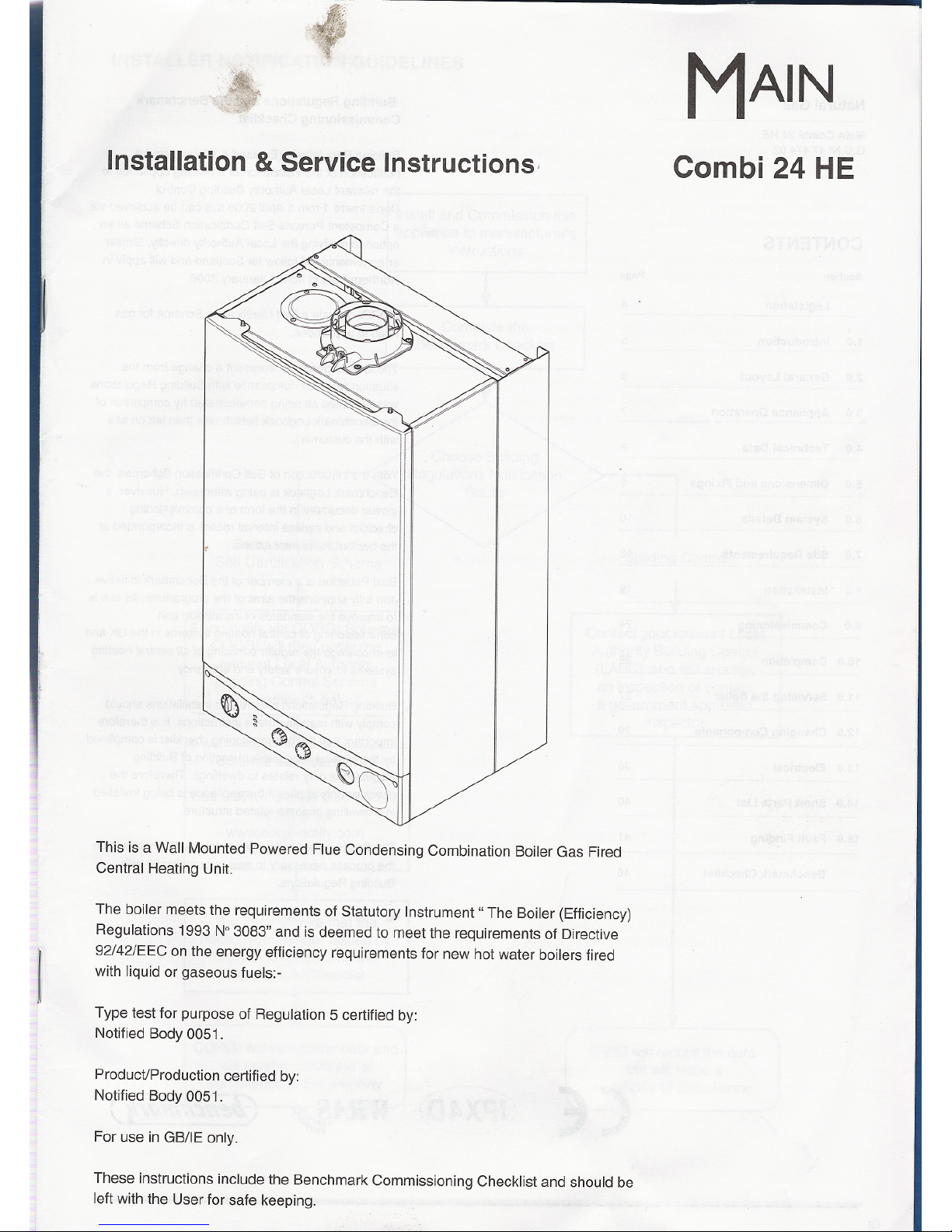
This is a Wall Mounted Powered Flue Condensing Combination Boiler Gas Fired
Central Heating Unit.
I
The boiler meetsthe requirements of Statutory Instrument" The Boiler (Efficiency)
Regulations 1993 N°3083" and is deemed to meet the requirements of Directive
92/42/EEC on the energy efficiency requirements for new hot water boilers fired
with liquid or gaseous fuels:-
Type test for purpose of Regulation 5 certified by:
Notified Body 0051.
Product/Production certified by:
Notified Body 0051.
For use in GB/IE only.
These instructions include the Benchmark Commissioning Checklist and should be
left with the Userfor safe keeping.
MAIN
Combi 24 HE
Natural Gas
Main Combi 24 HE
G.C.N' 47 474 02
CE
~https://manualmachine.com/?)
Building Regulations and the Benchmark
Commissioning Checklist
Building Regulations (England & Wales) require
notification of the installation of a heating appliance to
the relevant Local Authority Building Control
Department. From 1 April 2005 this can be achieved via
a Competent Persons Self Certification Scheme as an
option to notifying the Local Authority directly. Similar
arrangements will follow for Scotland and will apply in
Northern Ireland from 1 January 2006.
CORGI operate a Self Certification Scheme for gas
heating appliances.
These arrangements represent a change from the
situation whereby compliance with Building Regulations
was accepted as being demonstrated by completion of
the Benchmark Logbook (which was then left on site
with the customer).
With the introduction of Self Certification Schemes, the
Benchmark Logbook is being withdrawn. However, a
similar document in the form of a commissioning
checklist and service interval record is incorporated at
the back of these instructions.
Baxi PoUerton is a member of the Benchmark initiative
and fully supports the aims of the programme. Its aim is
to improve the standards of installation and
commissioning of central heating systems in the UK and
to encourage the regular servicing of all central heating
systems to ensure safety and efficiency.
Building Regulations require that installations should
comply with manufacturer's instructions. It is therefore
important that the commissioning checklist is completed
by the installer. The relevant section of Building
Regulations only relates to dwellings. Therefore the
checklist only applies if the appliance is being installed
in a dwelling or some related structure.
The flowchart opposite gives guidance for installers on
the process necessary to ensure compliance with
Building Regulations.
W.RII,
(/JenchlQfl!:l(j
I'll'
CONTENTS
Section
Page
Legislation
4
1.0 Introduction 5
2.0
General Layout
6
3.0
Appliance Operation
7
4.0 Technical Data 8
5.0
Dimensions and Fixings
9
6.0
System Details
10
7.0
Site Requirements
13
8.0
Installation
19
9.0
Commissioning
24
'"
10.0 Completion
26
11.0 Servicing the Boiler
27
12.0 Changing Components
29
13.0 Electrical 39
14.0 Short Parts List 40
15.0
Fault Finding
41
Benchmark Checklist 46
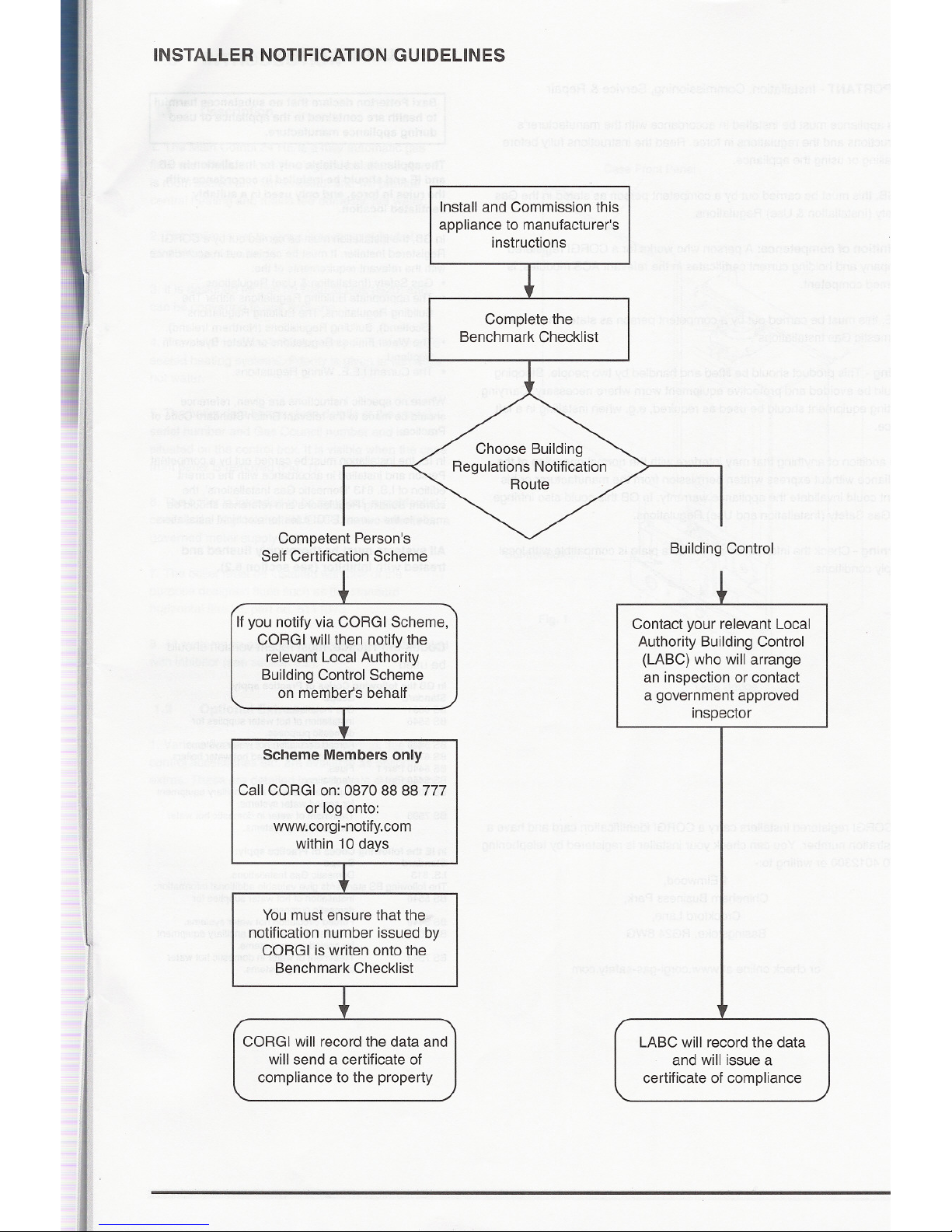
INSTALLER NOTIFICATION GUIDELINES
Install and Commission this
appliance to manufacturer's
instructions
Complete the
Benchmark Checklist
Competent Person's
Self Certification Scheme
~
Building Control
1
If you notify via CORGI Scheme,
CORGI will th~n notify the
relevant Local Authority
Building Control Scheme
on member's behalf
Contact your relevant Local
Authority Building Control
(LABC) who will arrange
an inspection or contact
a government approved
inspector
Scheme Members only
Call CORGI on: 0870 88 88 777
or log onto:
www.corgi-notify.com
within 10 days
You must ensure that the
notification number issued by
CORGI is writen onto the
Benchmark Checklist
"'"
CORGI will record the data and
will send a certificate of
compliance to the property
LABC will record the data
and will issue a
certificate of compliance
J
~
J
IMPORTANT -Installation, Commissioning, Service & Repair
This appliance must be installed in accordance with the manufacturer's
instructions and the regulations in force. Read the instructions fully before
installing or using the appliance. .
In GB, this must be carried out by a competent person as stated in the Gas
Safety (Installation & Use) Regulations.
Definition of competence: A person who works for a CORGI registered
company and holding current certificates in the relevant ACS modules, is
deemed competent.
In IE, this must be carried out by a competent person as stated in I.S. 813
"Domestic Gas Installations".
I
t
Lifting -This product should be lifted and handled by two people. Stooping
should be avoided and protective equipment worn where necessary. Carrying
& lifting equipment should be used as required, e.g. when installing in a loft
space.
The addition of anything that may interfere with the normal operation of the
appliance without express written permission from the manufacturer or his
agent could invalidate the appliance warranty. In GB this could also infringe
the Gas Safety (Installation and Use) Regulations.
Warning - Check the information on the data plate is compatible with local
supply conditions.
~
All CORGI registered installers carry a CORGI identification card and have a
registration number. You can check your installer is registered by telephoning
08704012300 or writing to:-
1 Elmwood,
Chineham Business Park,
Crockford Lane,
Basingstoke. RG24 8WG
or check online at www.corgi-gas-safety.com
If
II
=
LEGISLATION
Baxi Potterton declare that no substances harmful
to health are contained in the appliance or used
during appliance manufacture.
"'(heappliance is suitable only for installation in GB
and IEand should be installed in accordance with
the rules in force, and only used in a suitably
ventilated location.
In GB, the installation must be carried out by a CORGI
Registered Installer. It must be carried out in accordance
with the relevant requirements of the:
.Gas Safety (Installation & Use) Regulations.
.The appropriate Building Regulations either The
Building Regulations, The Building Regulations
(Scotland), Building Regulations (Northern Ireland).
.The Water Fittings Regulations or Water Byelaws in
Scotland.
.The Current I.E.E. Wiring Regulations.
Where no specific instructions are given, reference
should be made to the relevant British Standard Code of
Practice.
In IE, the installation must be carried out by a competent
Person and installed in accordance with the current
edition of I.S. 813 'Domestic Gas Installations', the
current Building Regulations and reference should be
made to the current ETCI rules for electrical installation.
All systems must be thoroughly flushed and
treated with inhibitor (see section 6.2).
Codes of Practice, most recent version should
be used
In GB the following Codes of Practice apply:
Standard Scope
BS 6891 Gas Installation.
BS 5546 Installation of hot water suppliesfor
domestic purposes.
Forced circulation hot water systems.
Installation of gas fired hotwater boilers.
Flues.
Ventilation.
Expansion vessels and ancillary equipment
for sealed watersystems.
Treatment of water in domestic hot water
central heating systems.
BS 5449
BS 6798
BS 5440 Part 1
BS 5440 Part 2
BS 7074
BS 7593
In IE the following Codes of Practice apply:
Standard Scope
I.S.813 Domestic Gas Installations.
The following BS standards give valuable additional information;
BS 5546 Installation of hot water supplies for
domestic purposes.
Forced circulation hot water systems.
Expansion vessels and ancillary equipment
for sealed water systems.
Treatment of water in domestic hot water
central heating systems.
BS 5449
BS 7074
BS 7593
1.0
INTRODUCTION
1.1
Description
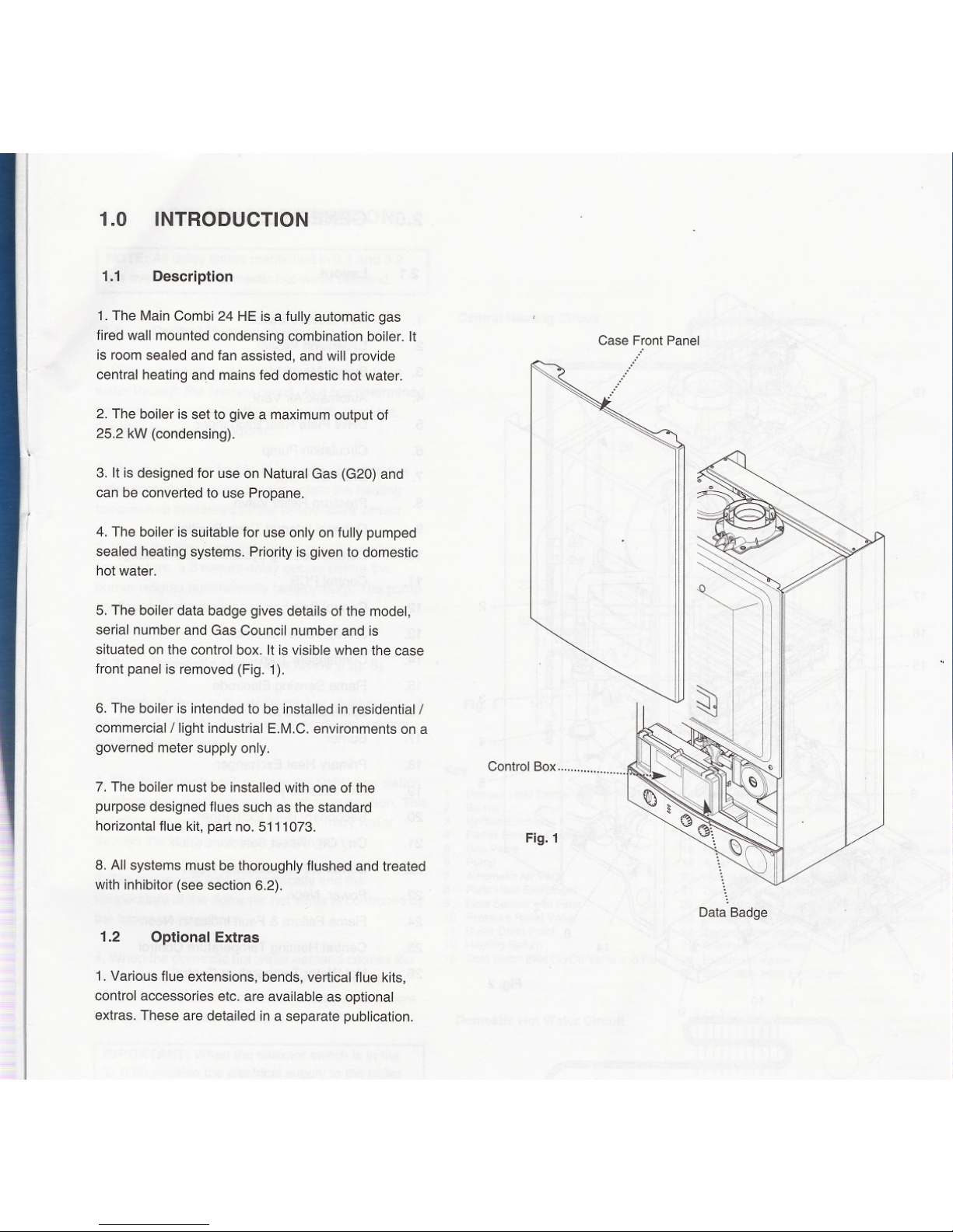
1. The Main Combi 24 HE is a fully automatic gas
fired wall mounted condensing combination boiler. It
is room sealed and fan assisted, and will provide
central heating and mains fed domestic hot water.
2. The boiler is set to give a maximum output of
25.2 kW (condensing).
3. It is designed for use on Natural Gas (G20) and
can be converted to use Propane.
4. The boiler is suitable for use only on fully pumped
sealed heating systems. Priority is given to domestic
hot water.
5. The boiler data badge gives details of the model,
serial number and Gas Council number and is
situated on the control box. It is visible when the case
front panel is removed (Fig. 1).
6. The boiler is intended to be installed in residential/
commercial/light industrial E.M.C. environments on a
governed meter supply only.
'"
7. The boiler must be installed with one of the
purpose designed flues such as the standard
horizontal flue kit, part no. 5111073.
8. All systems must be thoroughly flushed and treated
with inhibitor (see section 6.2).
1.2
Optional Extras
1. Various flue extensions, bends, vertical flue kits,
control accessories etc. are available as optional
extras. These are detailed in a separate publication.
Case Front Panel
Control Box .....................
Fig. 1
Data Badge
IMPORTANT -Installation, Commissioning, Service & Repair
This appliance must be installed in accordance with the manufacturer's
instructions and the regulations in force. Read the instructions fully before
installingor usingtheappliance. '
In GB, this must be carried out by a competent person as stated in the Gas
Safety (Installation & Use) Regulations.
Definition of competence: A person who works for a CORGI registered
company and holding current certificates in the relevant ACS modules, is
deemed competent.
In IE, this must be carried out by a competent person as stated in I.S. 813
"Domestic Gas Installations".
Lifting -This product should be lifted and handled by two people. Stooping
should be avoided and protective equipment worn where necessary. Carrying
& lifting equipment should be used as required, e.g. when installing in a loft
space.
The addition of anything that may interfere with the normal operation of the
appliance without express written permission from the manufacturer or his
agent could invalidate the appliance warranty. In GB this could also infringe
the Gas Safety (Installation and Use) Regulations.
Warning -Check the information on the data plate is compatible with local
supply conditions.
All CORGI registered installers carry a CORGI identification card and have a
registration number. You can check your installer is registered by telephoning
08704012300 or writing to:-
~
1 Elmwood,
Chineham Business Park,
Crockford Lane,
Basingstoke. RG24 8WG
or check online at www.corgi-gas-safety.com
LEGISLATION
Baxi Potterton declare that no substances harmful
to health are contained in the appliance or used
during appliance manufacture.
"(heappliance is suitable only for installation in GB
and IEand should be installed in accordance with
the rules in force, and only used in a suitably
ventilated location.
In GB, the installation must be carried out by a CORGI
Registered Installer. It must be carried out in accordance
with the relevant requirements of the:
.Gas Safety (Installation & Use) Regulations.
.The appropriate Building Regulations either The
Building Regulations, The Building Regulations
(Scotland), Building Regulations (Northern Ireland).
.The Water Fittings Regulations or Water Byelaws in
Scotland.
.The Current I.E.E. Wiring Regulations.
Where no specific instructions are given, reference
should be made to the relevant British Standard Code of
Practice.
In IE, the installation must be carried out by a competent
Person and installed in accordance with the current
edition of I.S. 813 'Domestic Gas Installations', the
current Building Regulations and reference should be
made to the current ETCI rules for electrical installation.
All systems must be thoroughly flushed and
treated with inhibitor (see section 6.2).
Codes of Practice, most recent version should
be used
In GB the following Codes of Practice apply:
Standard Scope
BS 6891 Gas Installation.
BS 5546 Installation of hot water supplies for
domestic purposes.
Forced circulation hot water systems.
Installation of gas fired hot water boilers.
Flues.
Ventilation.
Expansion vessels and ancillary equipment
for sealed water systems.
Treatment of water in domestic hot water
central heating systems.
BS 5449
BS 6798
BS 5440 Part 1
BS 5440 Part 2
BS 7074
BS 7593
In IE the following Codes of Practice apply:
Standard Scope
I.S.813 Domestic Gas Installations.
The following BS standards give valuable additional information;
BS 5546 Installation of hot water supplies for
domestic purposes.
Forced circulation hot water systems.
Expansion vessels and ancillary equipment
for sealed water systems.
Treatment of water in domestic hot water
central heating systems.
BS 5449
BS 7074
BS 7593
I.
I
8
..
14
12
11
10
9
0
:..~ h c=:>."""On
i ~ c=:> ,F,;I""
i Q c=:> Pow"ion
, j i
+
21 22
23
24
25
20
7
Fig.2
0
0
Fig.3
26
10 9
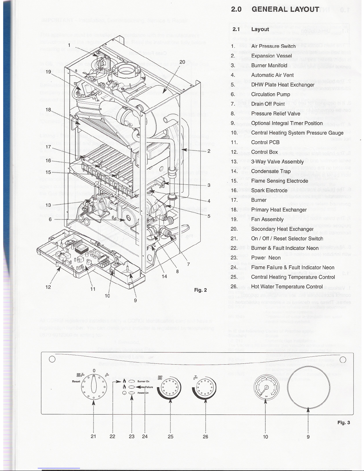
2.0
GENERAL LAYOUT
2.1
Layout
1.
Air Pressure Switch
2.
Expansion Vessel
3. Burner Manifold
4.
Automatic Air Vent
5.
DHW Plate Heat Exchanger
6.
Circulation Pump
7.
Drain Off Point
8. Pressure Relief Valve
9.
Optional Integral Timer Position
10.
Central Heating System Pressure Gauge
11.
Control PCB
12. Control Box
13.
3-Way Valve Assembly
14.
Condensate Trap
15.
Flame Sensing Electrode
16.
Spark Electrode
) j
""""".....4
17. Burner
18.
Primary Heat Exchanger
19.
Fan Assembly
20.
Secondary Heat Exchanger
21.
On / Off / Reset Selector Switch
22.
Burner & Fault Indicator Neon
23. Power Neon
24.
Flame Failure & Fault Indicator Neon
25.
Central Heating Temperature Control
26.
Hot Water Ternperature Control
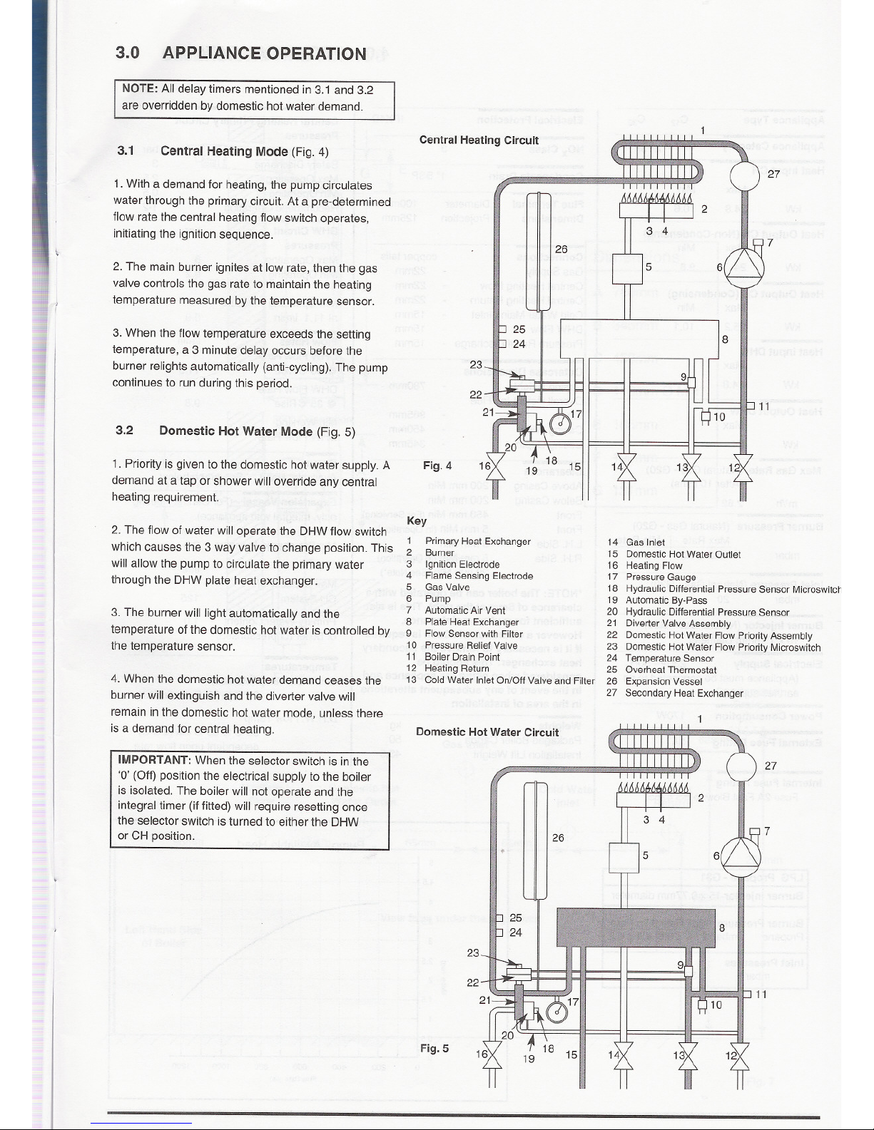
3.0
APPLIANCEOPERATION
NOTE: All delay timers mentioned in 3.1 and 3.2
are overridden by domestic hot water demand.
3.1
Central Heating Mode (Fig. 4)
1. With a demand for heating, the pump circulates
water through the primary circuit. At a pre-determined
flow rate the central heating flow switch operates,
initiating the ignition sequence.
2. The main burner ignites at low rate, then the gas
valve controls the gas rate to maintain the heating
temperature measured by the temperature sensor.
':I I
1/
I
I
3. When the flow temperature exceeds the setting
temperature, a 3 minute delay occurs before the
burner relights automatically (anti-cycling). The pump
continues to run during this period.
-
3.2
Domestic Hot Water Mode (Fig. 5)
1. Priority is given to the domestic hot water supply. A
demand at a tap or shower will override any central
heating requirement.
2. The flow of water will operate the DHW flow switch
which causes the 3 way valve to change position. This
will allow the pump to circulate the primary water
through the DHW plate heat exchanger.
3. The burner will light automatically and the
temperature of the domestic hot water is controlled by
the temperature sensor.
4. When the domestic hot water demand ceases the
burner will extinguish and the diverter valve will
remain in the domestic hot water mode, unless there
is a demand for central heating.
IMPORTANT: When the selector switch is in the
'0' (Off) position the electrical supply to the boiler
is isolated. The boiler will not operate and the
integral timer (if fitted) will require resetting once
the selector switch is turned to either the DHW
or CH position.
-
Fig. 4
7
Central Heating Circuit
27
26
6
23
11
Key
1 PrimaryHeat Exchanger
2 Burner
3 Ignition Electrode
4 Flame Sensing Electrode
5 Gas Valve
6 Pump
7 AutomaticAir Vent
8 Plate Heat Exchanger
9 Flow Sensor with Filter
10 Pressure ReliefValve
11 Boiler Drain Point
12 Heating Return
13 Cold Water Inlet On/Off Valve and Filter
14 Gas Inlet
15 Domestic Hot Water Outlet
16 Heating Flow
17 Pressure Gauge
18 Hydraulic Differential PressureSensor Microswitch
19 Automatic By-Pass
20 Hydraulic Differential Pressure Sensor
21 Diverter Valve Assembly
22 Domestic HotWater Flow PriorityAssembly
23 Domestic HotWater Flow PriorityMicroswitch
24 Temperature Sensor
25 Overheat Thermostat
26 Expansion Vessel
27 Secondary Heat Exchanger
Fig. 5
7
Domestic Hot Water Circuit
27
26
23
11
Heat Output CH(Non-Condensing)
Max Min
kW
24 9.8
Heat Output CH(Condensing)
Max Min
kW 25.2 10.1
Heat Input DHW
Max
kW 24.8
Heat Output DHW
Max
kW
24
Max Gas Rate (Natural Gas - G20)
(After 10 mins)
m3/h 2.62
Burner Pressure (NaturalGas - G20)
Max Rate Min Rate
mbar 10.2 :t 0.5 2 :t 0.2
Inlet Pressure (Natural Gas - G20)
mbar 20
Burner Injector (Natural Gas - G20)
15x 1.18mm Diameter
Electrical Supply 230V- 50Hz
(Appliance must be connected to an
earthed supply)
Power Consumption
170W
External Fuse Rating
3A
Internal Fuse Rating
Fuse 2A Fast Blow to BS 4265
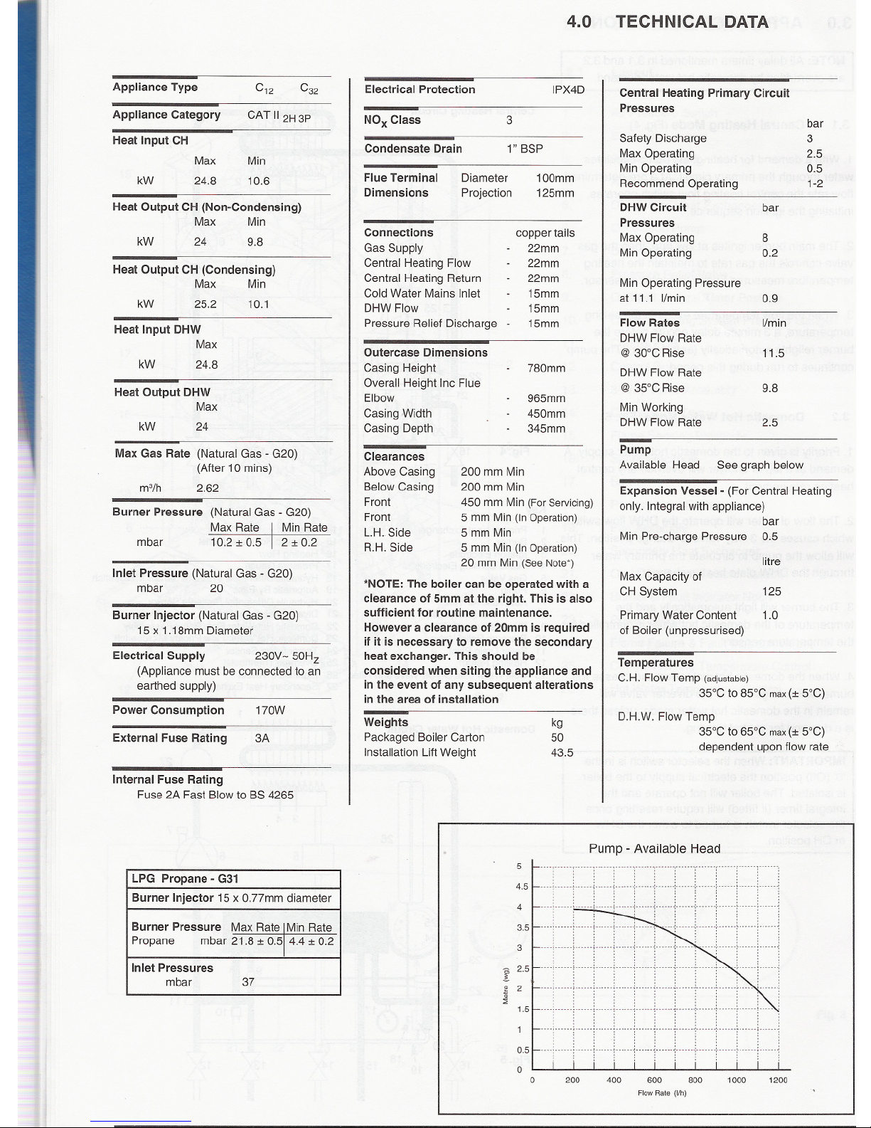
4.0
Electrical Protection IPX4D
NOx Class
3
Condensate Drain
1" BSP
Flue Terminal
Dimensions
Diameter
Projection
100mm
125mm
Connections
Gas Supply
Central Heating Flow
Central Heating Return
Cold Water Mains Inlet
DHW Flow
Pressure Relief Discharge -
copper tails
22mm
22mm
22mm
15mm
15mm
15mm
Outercase Dimensions
Casing Height
Overall Height Inc Flue
Elbow
Casing Width
Casing Depth
780mm
965mm
450mm
345mm
Clearances
Above Casing
Below Casing
Front
Front
L.H. Side
R.H. Side
200 mm Min
200 mm Min
450 mm Min (For Servicing)
5 mm Min (In Operation)
5 mm Min
5 mm Min (In Operation)
20 mm Min (See Note*)
*NOTE:
The boiler can be operated with a
clearance of 5mm at the right. This is also
sufficient for routine maintenance.
However a clearance of 20mm is required
if it is necessary to remove the secondary
heat exchanger. This should be
considered when siting the appliance and
in the event of any subsequent alterations
in the area of installation
Weights
Packaged Boiler Carton
Installation Lift Weight
kg
50
43.5
5
4.5
4
3.5
3
E2.5
~ 2
::;
1.5
0.5
0
0 200
TECHNICAL DATA
Central Heating Primary Circuit
Pressures
Pump
AvailableHead
See graph below
Expansion Vessel -(For Central Heating
only. Integral with appliance)
bar
Min Pre-charge Pressure 0.5
litre
Max Capacity of
CH System
Primary Water Content
of Boiler (unpressurised)
125
1.0
Temperatures
C.H. Flow Temp (adjustable)
35°C to 85°C max(:t 5°C)
D.HW. Flow Temp
35°C to 65°C max(:t 5°C)
dependent upon flow rate
Pump - Available Head
400 600 800 1000 1200
Flow Rate (I/h)
Appliance Type
C12
C32
Appliance Category
CAT II2H 3P
Heat Input CH
Max Min
kW 24.8 10.6
LPG Propane - G31
Burner Injector 15 x O.77mm diameter
Burner Pressure
Max Rate IMinRate
Propane
mbar 21.8 :t 0.514.4 :t 0.2
Inlet Pressures
mbar
37
bar
Safety Discharge
3
Max Operating
2.5
Min Operating
0.5
Recommend Operating
1-2
DHW Circuit bar
Pressures
Max Operating
8
Min Operating
0.2
Min Operating Pressure
at 11.1 I/min 0.9
Flow Rates I/min
DHW Flow Rate
@30°CRise 11.5
DHW Flow Rate
@35°CRise 9.8
Min Working
DHW Flow Rate 2.5
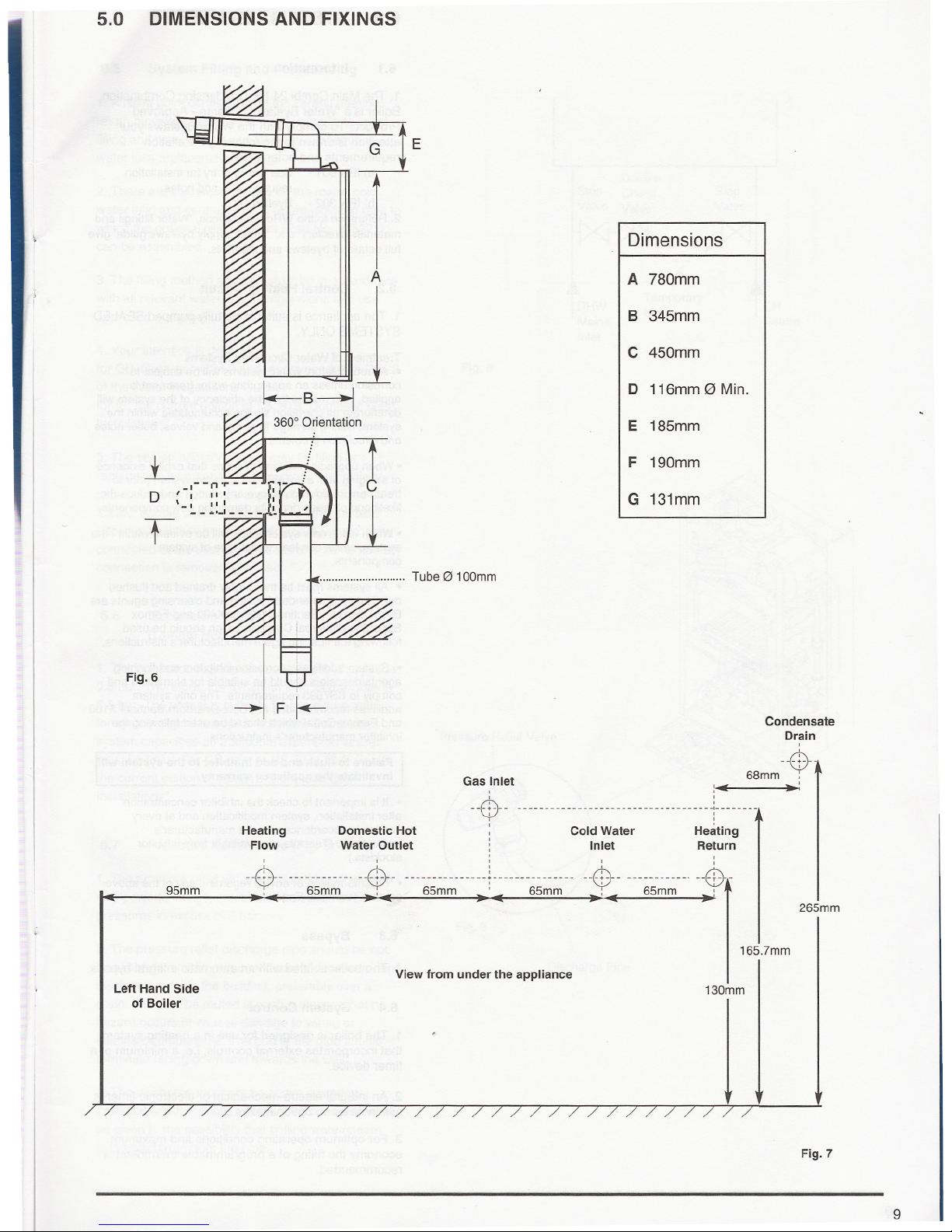
5.0 DIMENSIONS AND FIXINGS
J
"~
F~
k- B j
3600 Orientation
L F0::11 :
D ,_I--n~
Q)
"
\ I ",
f:k]
'
- . ,,' .
T
--.'-'-
I
,-
i7771r~ '
Fig.6
Heating
Flow
E
Dimensions
A
A 780mm
B 345mm
C 450mm
D 116mm0 Min.
E 185mm
T
c
1
F 190mm
G 131mm
, Tube 0 100mm
Gas Inlet
Condensate
Drain
,
u0 -.
68mm :
:11( .'
,
,
- - - - - - - - - - - - - - - - - - - - - - - - - - - - - - - - - - - -,- - - - - - --
: j
Heating
Return
,
--$--
Domestic Hot : Cold Water
Water Outlet ; Inlet
---U---u---ui u --0- un. u0r
65mm ' 65mm - : - 65mm -~
95mm
, ,
u0- u--- u$--
: - 65mm - ,
Left Hand Side
of Boiler
265mm
165.7mm
View from under the appliance
130mm
Fig. 7
9
6.0 SYSTEM DETAILS
6.1 Information
1. The Main Combi 24 HE Condensing Combination
Boiler is a 'Water Byelaws Scheme - Approved
Product'. To comply with the Water Byelaws your
attention is drawn to the following installation
requirements and notes (IRN).
a) IRN 001 - Seetext of entry for installation
requirements and notes.
b) IRN 302 - Byelaw 14.
2. Reference to the WRc publications, 'Water fittings and
materials directory' and 'Water supply byelaws guide' give
full details of byelaws and the IRNs.
6.2
Central Heating Circuit
1. The appliance is suitable for fully pumped SEALED
SYSTEMS ONLY.
Treatment of Water Circulating Systems
.All recirculatory water systems will be subject to
corrosion unless an appropriate water treatment is
applied. This means that the efficiency of the system will
deteriorate as corrosion sludge accumulates within the
system, risking damage to pump and valves, boiler noise
and circulation problems.
.When upgrading existing systems that exhibit evidence
of sludging, it is advisable to clean the system prior to
treatment in order to remove any sludge and reduce the
likelihood of these deposits damaging new components.
.When fitting new systems flux will be evident within the.
system, which can lead to damage of system
components.
.All systems must be thoroughly drained and flushed
out. The recommended flushing and cleansing agents are
Betz-Dearborn Sentinel X300 or X400 and Fernox
Superfloc Universal Cleanser which should be used
following the flushing agent manufacturer's instructions.
.System additives -corrosion inhibitors and flushing
agents/descalers should be suitable for aluminium and
comply to BS7593 requirements. The only system
additives recommended are Betz-Dearborn Sentinel X100
and Fernox-Copal which should be used following the
inhibitor manufacturer's instructions.
Failure to flush and add inhibitor to the system will
invalidate the appliance warranty.
.It is important to check the inhibitor concentration
after installation, system modification and at every
service in accordance with the manufacturer's
instructions. (Test kits are available from inhibitor
stockists.)
.For information or advice regarding any of the above
contact Technical Enquiries.
6.3
Bypass
1. The boiler is fitted with an automatic integral bypass.
6.4
System Control
1. The boiler is designed for use in a heating system
that incorporates external controls, Le. a minimum of a
timer device.
2. An integral electro-mechanical or electronic timer is
available as an optional extra.
3. For optimum operating conditions and maximum
economy the fitting of a programmable thermostat is
recommended.
6.0 SYSTEM DETAILS
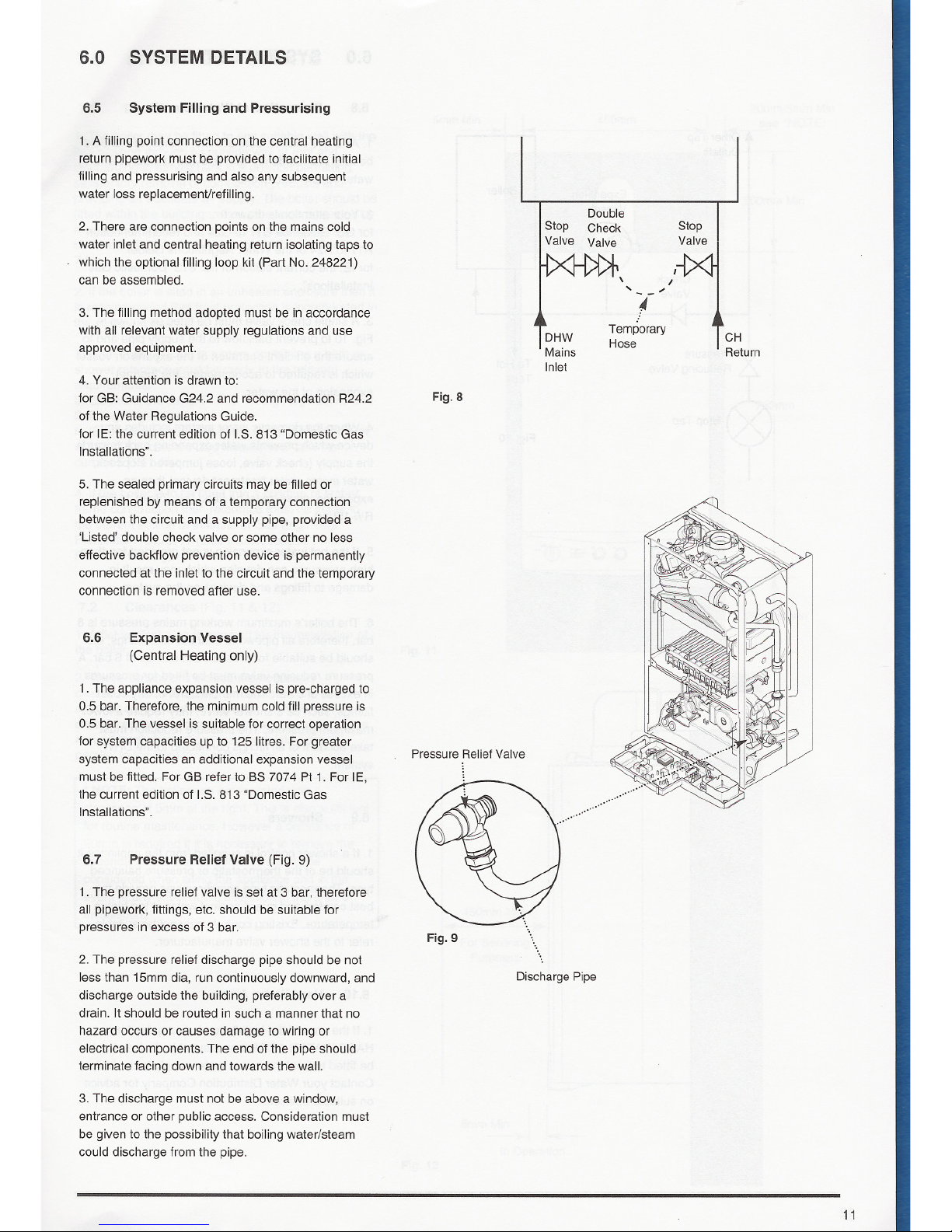
6.5
SystemFilling and Pressurising
1. A filling point connection on the central heating
return pipework must be provided to facilitate initial
filling and pressurising and also any subsequent
water loss replacemenVrefiliing.
2. There are connection points on the mains cold
water inlet and central heating return isolating taps to
which the optional filling loop kit (Part No. 248221)
can be assembled.
3. The filling method adopted must be in accordance
with all relevant water supply regulations and use
approved equipment.
4. Your attention is drawn to:
for GB: Guidance G24.2 and recommendation R24.2
of the Water Regulations Guide.
for IE: the current edition of I.S. 813 "Domestic Gas
Installations".
5. The sealed primary circuits may be filled or
replenished by means of a temporary connection
between the circuit and a supply pipe, provided a
'Listed' double check valve or some other no less
effective backflow prevention device is permanently
connected at the inlet to the circuit and the temporary
connection is removed after use.
6.6
Expansion Vessel
(Central Heating only)
1. The appliance expansion vessel is pre-charged to
0.5 bar. Therefore, the minimum cold fill pressure is
0.5 bar. The vessel is suitable for correct operation
for system capacities up to 125 litres. For greater
system capacities an additional expansion vessel
must be fitted. For GB refer to BS 7074 Pt 1. For IE,
the current edition of I.S. 813 "Domestic Gas
Installations" .
6.7
Pressure Relief Valve (Fig. 9)
1. The pressure relief valve is set at 3 bar, therefore
all pipework, fittings, etc. should be suitable for
pressures in excess of 3 bar.
2. The pressure relief discharge pipe should be not
less than 15mm dia, run continuously downward, and
discharge outside the building, preferably over a
drain. It should be routed in such a manner that no
hazard occurs or causes damage to wiring or
electrical components. The end of the pipe should
terminate facing down and towards the wall.
3. The discharge must not be above a window,
entrance or other public access. Consideration must
be given to the possibility that boiling water/steam
could discharge from the pipe.
Double
Stop Check
Valve Valve
Stop
Valve
DHW
Mains
Inlet
I
/
... .-
i-
Temporary
Hose
CH
Return
Fig. 8
Pressure Relief Valve
Fig. 9
Discharge Pipe
11
Other Tap
Outlets
Check
Valve
Stop Tap
Expansion
Vessel
6.0
SYSTEM DETAILS
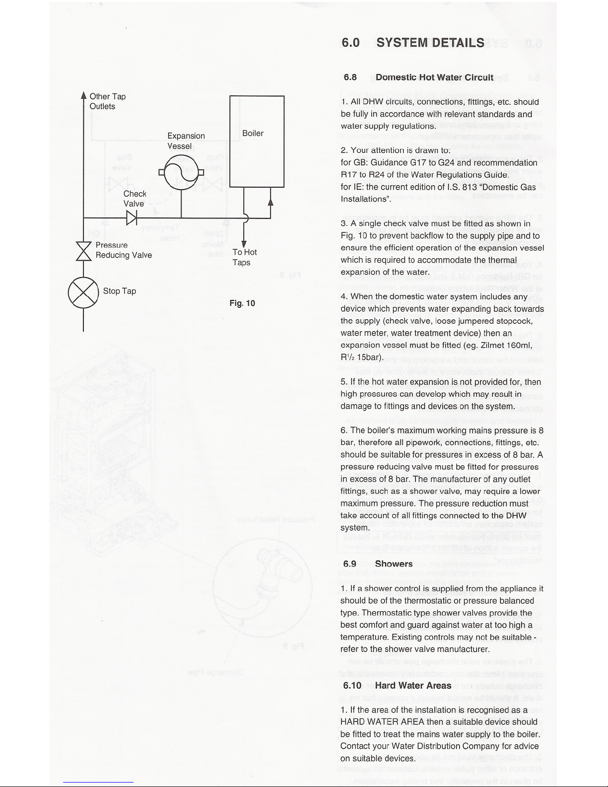
6.8
Domestic Hot Water Circuit
Boiler
1. All DHW circuits, connections, fittings, etc. should
be fully in accordance with relevant standards and
water supply regulations.
2. Your attention is drawn to:
for GB: Guidance G17 to G24 and recommendation
R17 to R24 of the Water Regulations Guide.
for IE: the current edition of 1.8.813 "Domestic Gas
Installations" .
To Hot
Taps
3. A single check valve must be fitted as shown in
Fig. 10 to prevent backflow to the supply pipe and to
ensure the efficient operation of the expansion vessel
which is required to accommodate the thermal
expansion of the water.
Fig. 10
4. When the domestic water system includes any
device which prevents water expanding back towards
the supply (check valve, loose jumpered stopcock,
water meter, water treatment device) then an
expansion vessel must be fitted (eg. Zilmet 160ml,
R'1215bar).
5. If the hot water expansion is not provided for, then
high pressures can develop which may result in
damage to fittings and devices on the system.
6. The boiler's maximum working mains pressure is 8
bar, therefore all pipework, connections, fittings, etc.
should be suitable for pressures in excess of 8 bar. A
pressure reducing valve must be fitted for pressures
in excess of 8 bar. The manufacturer of any outlet
fittings, such as a shower valve, may require a lower
maximum pressure. The pressure reduction must
take account of all fittings connected to the DHW
system.
6.9 Showers
1. If a shower control is supplied from the appliance it
should be of the thermostatic or pressure balanced
type. Thermostatic type shower valves provide the
best comfort and guard against water at too high a
temperature. Existing controls may not be suitable -
refer to the shower valve manufacturer.
6.10
Hard Water Areas
1. If the area of the installation is recognised as a
HARD WATER AREA then a suitable device should
be fitted to treat the mains water supply to the boiler.
Contact your Water Distribution Company for advice
on suitable devices.
7.0 SITE REQUIREMENTS
7.1
Location
1. The boiler may be fitted to any suitable wall with the
flue passing through an outside wall or roof and
discharging to atmosphere in a position permitting
satisfactory removal of combustion products and
providing an adequate air supply. The boiler should be
fitted within the building unless otherwise protected by
a suitable enclosure i.e. garage or outhouse. (The
boiler may be fitted inside a cupboard -see Section
7.3).
2. If the boiler is sited in an unheated enclosure then it
is recommended that frost protection is incorporated in
the control system.
3. If the boiler is fitted in a room containing a bath or
shower reference must be made to the relevant
requirements.
In GB this is the current lEE. Wiring Regulations and
Building Regulations.
In IE reference should be made to the current edition
of I.S. 813 "Domestic Gas Installations" and the
current ETCI rules.
4. If the boiler is to be fitted into a building of timber
frame construction then reference must be made to
the current edition of Institute of Gas Engineers
Publication IGE/UP/7 (Gas Installations in Timber
Framed Housing).
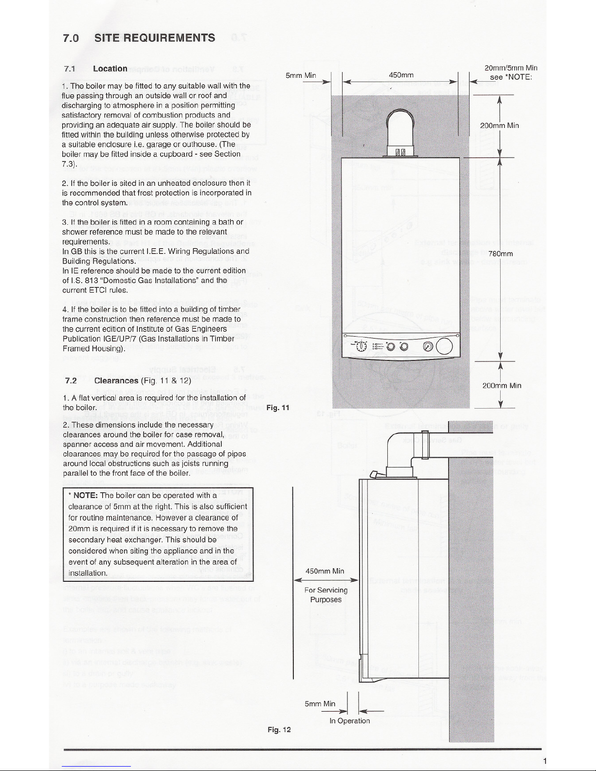
7.2
Clearances (Fig. 11 & 12)
1. A flat vertical area is required for the installation of
the boiler.
2. These dimensions include the necessary
clearances around the boiler for case removal,
spanner access and air movement. Additional
clearances may be required for the passage of pipes
around local obstructions such as joists running
parallel to the front face of the boiler.
* NOTE: The boiler can be operated with a
ctearance of 5mm at the right. This is also sufficient
for routine maintenance. However a clearance of
20mm is required if it is necessary to remove the
secondary heat exchanger. This should be
considered when siting the appliance and in the
event of any subsequent alteration in the area of
installation.
450mm
20mm/5mm Min
see *NOTE:
t
200mm Min
780mm
Fig. 11
r
200mm Min
---L
450mm Min
01( .-
For Servicing
Purposes
5mm~ L
In Operation
Fig. 12
7.0 SITE REQUIREMENTS
7.3
Ventilation of Compartments
1. Where the appliance is installed in a cupboard or
compartment, no air vents are required.
2. BS 5440: Part 2 refers to room sealed appliances
installed in compartments. The appliance will run
sufficiently cool without ventilation.
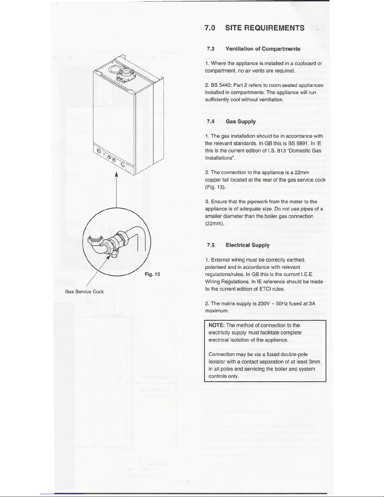
7.4
Gas Supply
1. The gas installation should be in accordance with
the relevant standards. In GB this is BS 6891. In IE
this isthe current edition of I.S. 813 "Domestic Gas
Installations" .
2. The connection to the appliance is a 22mm
copper tail located at the rear of the gas service cock
(Fig. 13).
3. Ensure that the pipework from the meter to the
appliance is of adequate size. Do not use pipes of a
smaller diameter than the boiler gas connection
(22mm).
7.5
Electrical Supply
Fig. 13
1. External wiring must be correctly earthed,
polarised and in accordance with relevant
regulations/rules. In GB this is the current I.E.E.
Wiring Regulations. In IE reference should be made
to the current edition of ETCI rules.
Gas Service Cock
2. The mains supply is 230V -50Hz fused at 3A
maximum.
NOTE: The method of connection to the
electricity supply must facilitate complete
electrical isolation of the appliance.
Connection may be via a fused double-pole
isolator with a contact separation of at least 3mm
in all poles and servicing the boiler and system
controls only.
 Loading...