

Page 1
© Baxi Heating UK Ltd 2009
Baxi Bermuda BBU 15 HE
Condensing Back Boiler Unit
These Instructions must be read in conjunction with those for
the separate Valor Dimension electric firefront.
They include the Benchmark Commissioning Checklist
and should be left with the user for safe keeping.
Installation & Servicing Instructions
Page 2

2
© Baxi Heating UK Ltd 2009
Natural Gas
Baxi Bermuda BBU 15 HE
G.C.No. 44 075 09
For use with the following electric firefronts:
Valor Dimension Classica Brass, Pewter or Black BBU Firefront
Valor Dimension Dream Gold, Chrome or Black BBU Firefront
Valor Dimension Innova BBU Firefront
Valor Dimension Regalia BBU Firefront
Valor Dimension Nano Chrome BBU Firefront
Valor Dimension Lyrica BBU Firefront
Building Regulations and the Benchmark
Commissioning Checklist
Building Regulations (England & Wales) require notification of
the installation of a heating appliance to the relevant Local
Authority Building Control Department. From 1 April 2005 this
can be achieved via a Competent Persons Self Certification
Scheme as an option to notifying the Local Authority directly.
Similar arrangements will follow for Scotland and will apply in
Northern Ireland from 1 January 2006.
The Health & Safety Executive operates the ‘Gas Safe Register’,
a self-certification scheme for gas heating appliances.
These arrangements represent a change from the situation
whereby compliance with Building Regulations was accepted as
being demonstrated by completion of the Benchmark Logbook
(which was then left on site with the customer).
With the introduction of Self Certification Schemes, the
Benchmark Logbook is being withdrawn. However, a similar
document in the form of a commissioning checklist and service
interval record is incorporated at the back of these instructions.
This company is a member of the Benchmark initiative and fully
supports the aims of the programme. Its aim is to improve the
standards of installation and commissioning of central heating
systems in the UK and to encourage the regular servicing of all
central heating systems to ensure safety and efficiency.
Building Regulations require that installations should comply
with manufacturer's instructions. It is therefore important that
the commissioning checklist is completed by the installer. The
relevant section of Building Regulations only relates to
dwellings. Therefore the checklist only applies if the appliance is
being installed in a dwelling or some related structure.
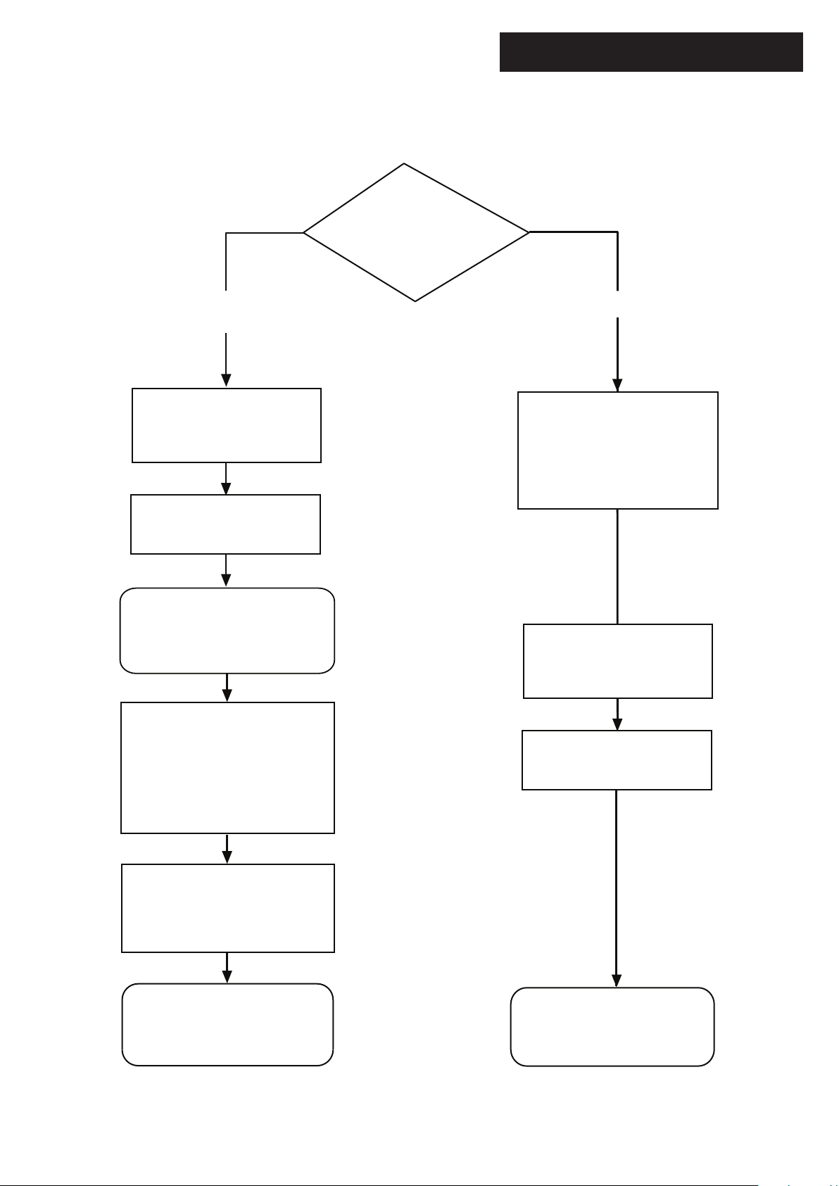
The flowchart opposite gives guidance for installers on the
process necessary to ensure compliance with Building
Regulations.
0086
ISO 9001
FM 00866
This product has an energy rating (A) on a scale of A to G.
For more information see www.boilers.org.uk. This is a certification mark.
© Baxi Heating UK Ltd 2009 All rights reserved. No part of this publication may
be reproduced or transmitted in any form or by any means, or stored in any
retrieval system of any nature (including in any database), in each case whether
electronic, mechanical, recording or otherwise, without the prior written
permission of the copyright owner, except for permitted fair dealing under
Copyrights, Designs and Patents Act 1988.
Applications for the copyright owner’s permission to reproduce or make other
use of any part of this publication should be made, giving details of the proposed
use, to the following address:
The Company Secretary, Baxi Heating UK Ltd, The Wyvern Business Park,
Stanier Way, Derby, DE21 6BF.
Full acknowledgement of author and source must be given.
WARNING: Any person who does any unauthorised act in relation to a
copyright work may be liable to criminal prosecution and civil claims for damages.
The Benchmark Scheme
Benchmark places responsibilities on both manufacturers and installers. The
purpose is to ensure that customers are provided with the correct equipment for
their needs, that it is installed, commissioned and serviced in accordance with the
manufacturer’s instructions by competent persons and that it meets the
requirements of the appropriate Building Regulations. The Benchmark Checklist
can be used to demonstrate compliance with Building Regulations and should be
provided to the customer for future reference.
Installers are required to carry out installation, commissioning and servicing work
in accordance with the Benchmark Code of Practice which is available from the
Heating and Hotwater Industry Council who manage and promote the Scheme.
Visit www.centralheating.co.uk for more information.
Page 3
Installer Notification Guidelines
3
© Baxi Heating UK Ltd 2009
Choose Building
Regulations Notification
Route
Competent Person's
Self Certification Scheme
Install and Commission this
appliance to manufacturer's
instructions
Complete the
Benchmark Checklist
If you notify via the ‘Gas Safe
Register’, the register will issue
the Building Regulations
certificate on members’ behalf
Building Control
Contact your relevant Local
Authority Building Control
(LABC) who will arrange
an inspection or contact
a government approved
inspector
Install and Commission this
appliance to manufacturer's
instructions
Scheme Members only
Call ‘Gas Safe Register’ on:
0800 408 5577
or log onto:
www.GasSafeRegister.co.uk
within 10 days
You must ensure that the
certificate number issued by
the ‘Gas Safe Register’ is written
onto the Benchmark Checklist
‘Gas Safe Register’ will issue a
Building Regulations Compliance
Certificate to the property owner
and inform the relevant LABC
Complete the
Benchmark Checklist
LABC will record the data
and will issue a
certificate of compliance
Page 4

Legislation
4
© Baxi Heating UK Ltd 2009
Codes of Practice, most recent version should be used
In GB the following Codes of Practice apply:
Standard Scope
BS 6891 Gas Installation.
BS 5546 Installation of hot water supplies for
domestic purposes.
BS 5449 Forced circulation hot water systems.
BS 6798 Installation of gas fired hot water boilers.
BS 5440 Part 1 Chimneys.
BS 5440 Part 2 Ventilation.
BS 7074 Expansion vessels and ancillary equipment for
sealed water systems.
BS 7593 Treatment of water in domestic hot water central
heating systems.
Also the following standard includes relevant information about
builders openings:
BS 5871 Part 1 Installation of gas fires, convector heaters,
fire/back boilers and heating stoves.
In IE the following Codes of Practice apply:
Standard Scope
I.S. 813 Domestic Gas Installations.
The following BS standards give valuable additional information;
BS 5546 Installation of hot water supplies for
domestic purposes.
BS 5449 Forced circulation hot water systems.
IMPORTANT - Installation, Commissioning, Service & Repair
This appliance must be installed in accordance with the manufacturer’s instructions and
the regulations in force. Read the instructions fully before installing or using the
appliance.
In GB, this must be carried out by a competent person as stated in the Gas Safety
(Installation & Use) Regulations.
Definition of competence: A person who works for a Gas Safe registered company
and holding current certificates in the relevant ACS modules, is deemed competent.
In IE, this must be carried out by a competent person as stated in I.S. 813 “Domestic
Gas Installations”.
The addition of anything that may interfere with the normal operation of the appliance
without express written permission from the manufacturer or his agent could invalidate
the appliance warranty. In GB this could also infringe the Gas Safety (Installation and
Use) Regulations.
Warning - Check the information on the data plate is compatible with local supply
conditions.
This company declare that no substances harmful to health
are contained in the appliance or used during appliance
manufacture.
The appliance is suitable only for installation in GB and IE and
should be installed in accordance with the rules in force, and
only used in a suitably ventilated location.
In GB, the installation must be carried out by a Gas Safe
Registered Installer. It must be carried out in accordance with
the relevant requirements of the:
• Gas Safety (Installation & Use) Regulations.
• The appropriate Building Regulations either The Building
Regulations, The Building Regulations (Scotland), Building
Regulations (Northern Ireland).
• The Water Fittings Regulations or Water Byelaws in
Scotland.
• The Current I.E.E. Wiring Regulations.
Where no specific instructions are given, reference should be
made to the relevant British Standard Code of Practice.
In IE, the installation must be carried out by a competent
Person and installed in accordance with the current edition of
I.S. 813 ‘Domestic Gas Installations’, the current Building
Regulations and reference should be made to the current ETCI
rules for electrical installation.
All systems must be thoroughly flushed and treated with
inhibitor (see section 6.2).
The boiler meets the requirements of Statutory Instrument “ The Boiler (Efficiency)
Regulations 1993 N
o
3083” and is deemed to meet the requirements of Directive
92/42/EEC on the energy efficiency requirements for new hot water boilers fired with
liquid or gaseous fuels:-
Type test for purpose of Regulation 5 certified by:
Notified Body 0087.
Product/Production certified by:
Notified Bodies 0086.
For GB/IE only.
All Gas Safe registered engineers carry an ID card with their licence number and a
photograph. You can check your engineer is registered by telephoning
0800 408 5500 or online at www.GasSafeRegister.co.uk
Page 5

Safe Manual Handling
5
© Baxi Heating UK Ltd 2009
General
The following advice should be adhered to, from when first handling the boiler to the final stages of installation, and also during maintenance.
Most injuries as a result of inappropriate handling and lifting are to the back, but all other parts of the body are vulnerable, particularly shoulders, arms and hands.
Health & Safety is the responsibility of EVERYONE.
There is no ‘safe’ limit for one man - each person has different capabilities. The boiler should be handled and lifted by TWO PEOPLE.
Do not handle or lift unless you feel physically able.
Wear appropriate Personal Protection Equipment e.g. protective gloves, safety footwear etc.
Preparation
Co-ordinate movements - know where, and when, you are both going.
Minimise the number of times needed to move the boiler - plan ahead.
Always ensure when handling or lifting the route is clear and unobstructed. If possible avoid steps, wet or slippery surfaces, unlit areas etc. and take special care
on ladders/into lofts.
Technique
When handling or lifting always use safe techniques - keep your back straight, bend your knees. Don’t twist - move your feet, avoid bending forwards and
sideways and keep the load as close to your body as possible.
Where possible transport the boiler using a sack truck or other suitable trolley.
Always grip the boiler firmly, and before lifting feel where the weight is concentrated to establish the centre of gravity, repositioning yourself as necessary. See the
‘Installation’ section of these instructions for recommended lift points.
Remember
The circumstances of each installation are different. Always asses the risks associated with handling and lifting according to the individual conditions.
If at any time when installing the boiler you feel that you may have injured yourself STOP !!
DO NOT ‘work through’ the pain - you may cause further injury.
IF IN ANY DOUBT DO NOT HANDLE OR LIFT THE BOILER - OBTAIN ADVICE OR ASSISTANCE BEFORE PROCEEDING !!
Working at Height
In order to reduce the number of fatalities and major accidents attributable to working at height, the Health and Safety Executive has introduced comprehensive
regulations and guidance that should be followed by all businesses working at height.
The following paragraphs consider some of the main features of the regulations and guidance. This is, however, only a limited summary and it is recommended
that all businesses planning on undertaking air source heat pump heating installations obtain a copy of the regulations and guidance issued by the Health and
Safety Executive and carefully consider the contents.
The regulations and guidance state that you are required to carry out a risk assessment for all work conducted at height and to put in place arrangements for:
• Eliminating or minimising risks from work at height.
• Safe systems of work for organising and performing work at height.
• Safe systems for selecting suitable work equipment.
• Safe systems for protecting people from the consequences of work at height.
The regulations and guidance highlight a hierarchy for safe work at height:
• Avoid the risk by not working at height if practicable.
• Prevent falls. Where it is not reasonably practicable to avoid work at height, you are required to take suitable and sufficient steps to prevent the risk of a fall
including selecting the most suitable work equipment (in accordance with the regulations).
• Mitigate the consequences of a fall; where the risk of a person or object falling still remains, take suitable and sufficient measures to minimise
the distance and consequences of any fall.
Collective protection measures, such as guard rails on scaffold, should be given priority over personal protection measures, such as safety harnesses.
Within the regulations’ framework, you are required to:
1) Assess the risk to help you decide how to work safely.
2) Follow the hierarchy for safe work at height (i.e. avoid, prevent and mitigate).
3) Plan and organise your work properly, taking account of weather conditions and the possibility of emergencies.
4) Make sure those working at height are competent.
5) Make use of appropriate work equipment.
6) Manage the risks from working on or around fragile surfaces and from falling objects.
7) Inspect and maintain the work equipment to be used and inspect the place where the work will be carried out for both access and egress.
Page 6
6
© Baxi Heating UK Ltd 2009
1.0 Introduction 7
2.0 General Layout 8
3.0 Technical Data 10
4.0 System Details 11
5.0 Site Requirements 15
6.0 Boiler Internal Wiring 20
7.0 Installation 21
8.0 Completion & Commissioning 25
9.0 Annual Servicing 27
10.0 Changing Components 29
11.0 Setting the Gas Valve 33
12.0 Fault Finding 34
13.0 Short Parts List 38
14.0 Notes 39
Benchmark Checklist 42
Section Page
Contents
Page 7
1.0 Introduction
© Baxi Heating UK Ltd 2009
1.1 Description
1. The Baxi Bermuda BBU 15 HE is a central heating
boiler designed for installation within a builders opening
in the living space of a dwelling.
2. The boiler is a fully automatic gas fired condensing
boiler. It is room sealed and fan assisted.
3. The boiler output will automatically modulate
between:
Max Min
15kW 4.6kW
15.7kW (condensing) 4.83kW (condensing)
According to system load
4. It must be fitted in conjunction with one of the
available electric firefront units as listed on page 2.
The separate electric firefront is intended for hearth
mounting. All instructions, fixings etc. needed to fit the
firefront are included in the firefront pack.
5. These instructions relate to the central heating boiler
section of the appliance (Fig. 1).
6. The appliance is designed for use on NATURAL
GAS (G20) only.
7. It can be used on sealed or open vented systems.
It must NOT be fitted on any type of gravity system.
The boiler is suitable for fully pumped systems ONLY.
8. The boiler is fitted with an integral pump unit for the
removal of condensate.
9. The boiler data badge gives details of the model,
serial number and Gas Council number and is situated
on the front case panel.
10. The boiler is intended to be installed in a residential
environment on a governed meter supply only.
11. The boiler must be installed with one of the
MULTIIFIT vertical concentric Flexi Flue kits available:10m kit 720101701 or 12.5m kit 720102001.
12. All systems must be thoroughly flushed and
treated with inhibitor (see section 4.2).
1.2 Contents
1. The boiler pack contains:
• Boiler Unit
• Plumbing Kit
• Condensate Pipe & Elbow
• Fixings Kit
• Literature Pack
2. The flue pack contains:
• Terminal Cap
• Flue Duct Adaptor (inc. seal)
• Air Cowl
• Air Duct Collar (inc. 4 screws)
• Air Duct Clamp
• Closure Plate
• Boiler Concentric
Adaptor (inc. 2 seals)
• 10m or 12.5m of Concentric
Flexible Duct
• 2 x 60mm grey Seals
• 1 x 100mm red Seal
Fig. 1
7
Fig. 2
Page 8
2.0 General Layout
8
© Baxi Heating UK Ltd 2009
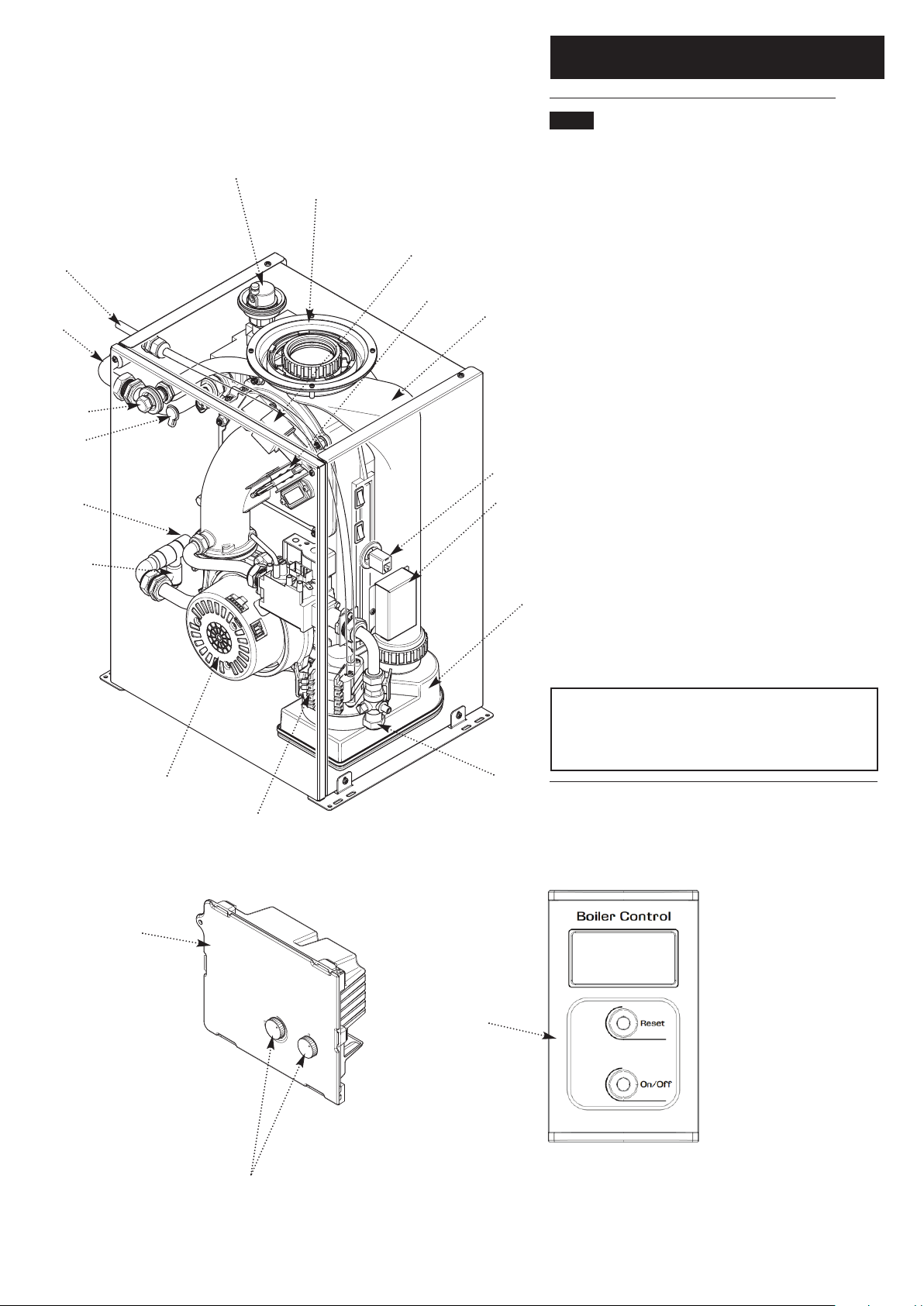
2.1 Layout (Fig. 3)
1. Automatic Air Vent
2. Flue Connection
3. Spark Generator
4. Spark & Sensing Electrodes
5. Heat Exchanger
6. Boiler Control Connector
7. Control Wiring Connector
8. Condensate Sump
9. Gas Cock
10. Condensate Pump
11. Fan
12. Drain
13. Return Connection
14. Air Sampling Point
15. Flue Sampling Point
16. Flow Connection
17. Condensate Outlet
18. PCB Control Box (shown removed for clarity)
19. Boiler Control (cover open)
The Boiler Control operates the boiler remotely. This is
supplied with the firefront and is fitted, in operation, to the
firefront spacer frame.
IMPORTANT: To commission the boiler it is is necessary
to remove the Boiler Control from the firefront
packaging and connect it to the boiler at the upper right
hand side (item 6).
1
2
3
4
5
6
7
8
9
10
11
12
13
17
16
15
14
18
Calibration Controls
Fig. 3
19
PCB Control Box
removed for clarity
PCB Control Box
Page 9
9
© Baxi Heating UK Ltd 2009
2.0 General Layout
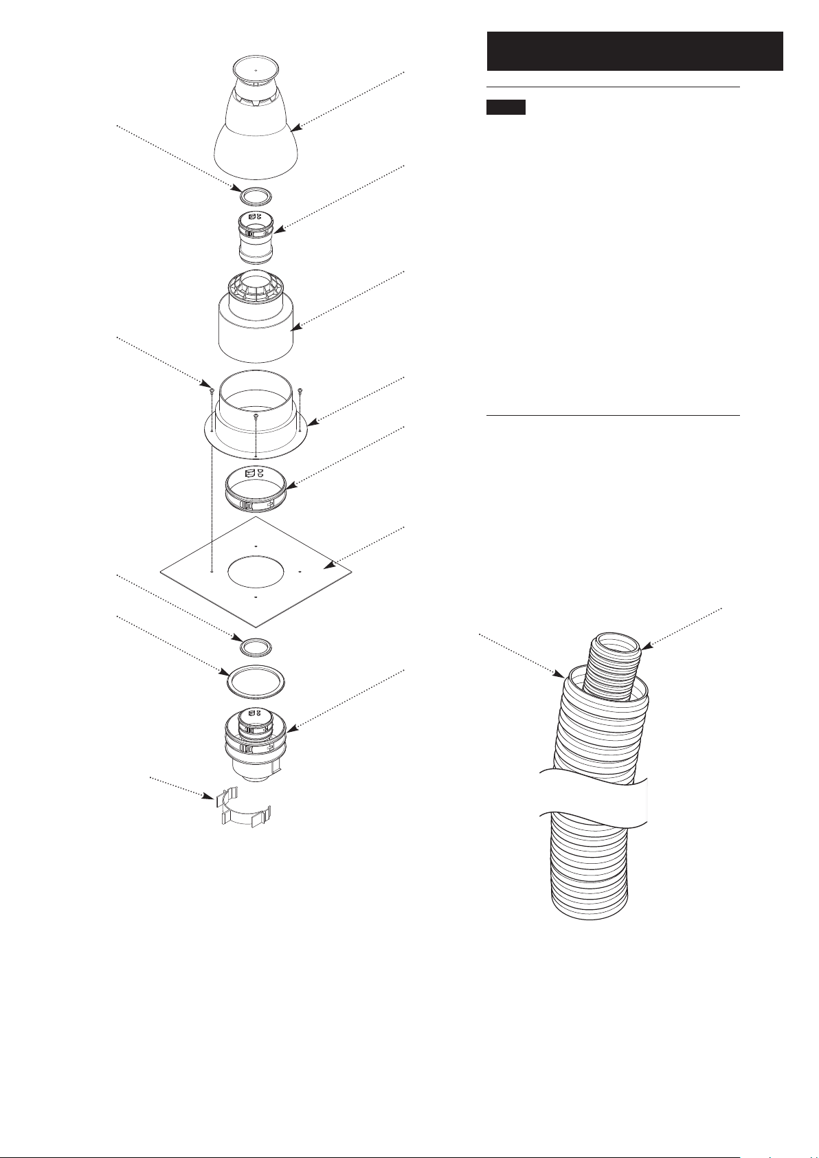
2.2 Flue Kit (10m & 12.5m) (Fig. 3a)
1. Terminal Cap
2. Flue Duct Adaptor
3. Air Cowl
4. Air Duct Collar
5. Air Duct Clamp
6. Closure Plate
7. Boiler Adaptor
8. 60mm Ø Seal
9. Collar Securing Screws x 4
10. 100mm Ø Seal
11. 60mm Ø Flue Duct
12. 100mm Ø Air Duct
13. ‘C’ Clip
1
2
3
4
5
6
7
8
9
10
8
11
12
Fig. 3a
13
Page 10
10
© Baxi Heating UK Ltd 2009
Sedbuk Declaration For Bermuda
BBU 15 HE
The seasonal efficiency (SEDBUK) is 90.1%
This value is used in the UK Government’s
Standard Assessment Procedure (SAP) for energy
rating of dwellings. The test data from which it has
been calculated has been certified by 0087.
Appliance Category CAT I
2H
Inlet Pressure (Natural Gas - G20)
mbar 20
Injector (Natural Gas - G20)
420 (4.2 mm)
Appliance Type C
33
3.0 Technical Data
3.1 Bermuda HE CBBU 15 HE
NOxClass 5 (31mg/kWh)
Heat Input (Net) Max Min
kW 15.4 5.0
Heat Input (Gross) Max Min
kW 17.1 5.7
Heat Output (Non-Condensing)
Max Min
kW 15.0 4.88
Heat Output (Condensing)
Max Min
kW 15.7 5.25
Gas Rate (Natural Gas - G20)
(After 10 mins)
Max Min
m3/h 1.63 0.54
Electrical Supply 230V~ 50H
z
(Appliance must be connected to an
earthed supply)
Boiler Power Consumption
112W
Boiler Electrical Protection
IPX0
Boiler External Fuse Rating 3A
Connections
Gas Supply - 15mm compression
Flow - 22mm male copper
Return - 22mm male copper
Weights
Packaged Boiler Carton 28 kg
Installation Lift Weight 27 kg
Flue Length Max Min
Metres 12.5 3.0
Dimensions
Casing Height - 538mm
Casing Width - 383mm
Casing Depth - 306mm
Boiler Set Temperature
Max Min
°C 75 25
Firefront
See the instructions supplied with the firefront for
all Technical Data
Page 11
4.0 System Details
11
© Baxi Heating UK Ltd 2009
4.1 Water Circulating Systems
1. The appliance is suitable for use on fully pumped
systems ONLY which may be sealed or open vented.
2. The following conditions should be observed at all
times:
The static head must not exceed 30m
of water.
The static head must not be less than
1m of water.
The boiler must not be used with a
direct cylinder.
Drain cocks should be fitted to all
system low points.
All gas and water pipes and electrical
wiring must be installed in such a way
that they do not restrict the servicing of
the boiler.
Position isolating valves as close as
possible to the circulating pump.
There is a drain cock supplied in the
plumbing kit.
4.2 Treatment of Water Circulating
Systems
All recirculatory water systems will be subject to
corrosion unless they are flushed and an appropriate
water treatment is applied. To prevent this, follow the
guidelines given in BS 7593 “Treatment of Water in
Domestic Hot Water Central Heating Systems” and
the treatment manufacturers instructions.
Treatment must involve the use of a proprietary
cleanser, such as Sentinel X300 or X400, or Fernox F3
and an inhibitor such as Sentinel X100 or Fernox MB-1.
Full instructions are supplied with the products, for
further information contact Sentinel (0800 389 4670)
or Fernox (0870 870 0362).
Failure to flush and add inhibitor to the system will
invalidate the appliance warranty.
It is important to check the inhibitor concentration after
installation, system modification and at every service in
accordance with the inhibitor manufacturer’s
instructions. (Test kits are available from inhibitor
stockists.)
For information or advice regarding any of the above
contact Technical Enquiries 0844 871 1555.
Page 12
4.3 Pipework
1. The sizes of the flow and return pipes from the
boiler should be determined by normal methods
according to the requirements of the system.
2. It is recommended that the system is designed for a
drop in temperature across the system of between
11& 20°C.
3. In systems using non-metallic pipework it is
necessary to use copper pipe for the boiler Flow and
Return. The copper must extend at least 1 metre from
the boiler and include any branches. The copper pipe
must not be insulated (Fig. 4).
4.4 System Controls
1. The system in which the appliance is installed should
include a control system.
2. Such a system would comprise a timer control and a
separate room and/or cylinder thermostat as
appropriate.
3. The boiler should be controlled so that it operates
on demand only.
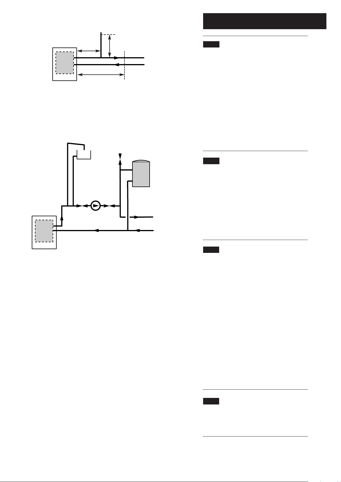
4.5 Fully Pumped Open Vent System (Fig. 5)
1. The sizes of the system pipes should be determined
by normal methods.
2. The open vent pipe should be a minimum of 22mm
and must rise continuously to a point above the feed
and expansion tank.
3. The flow pipe from the boiler form part of the vent
pipe. No part of the open vent may contain a valve.
4. Inverted pipe runs must be avoided.
5. On low capacity systems with a maximum available
flow rate of less than 8.3l/min (temperature differential
›25°C) an external bypass must be fitted .
6. The bypass must be of the automatic pressure
operated type.
4.6 Storage Systems
1. For information regarding the use of a Bermuda
BBU 15 HE boiler with a storage system, contact the
appropriate storage system manufacturer.
4.0 System Details
12
© Baxi Heating UK Ltd 2009
Air Vent
Boiler
Pump
Radiator
Circuit
Fully Pumped System
22mm
Open Vent
15mm
Cold
Feed
Indirect
Cylinder
Return
Flow
Fig. 5
Boiler
Flow
Return
Copper
0.5m
Copper
1m
Copper
0.5m
Fig. 4
Page 13
4.0 System Details
13
© Baxi Heating UK Ltd 2009
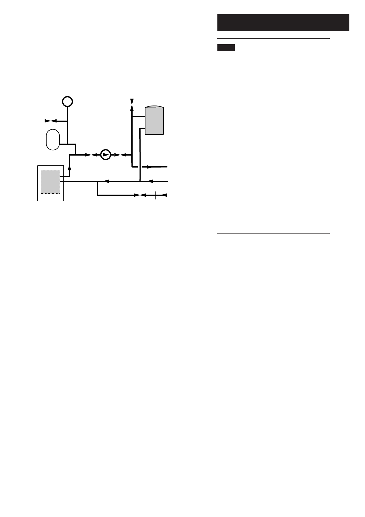
4.7 Sealed Systems (Figs. 6, 7 & 8)
1. Installation. The installation must comply with the
requirements of BS 6798 and BS EN 12828. The British
Gas publication “British Gas Specification for Domestic
Wet Central Heating Systems” should also be
consulted.
2. Pressure Relief Valve. A non-adjustable spring loaded
pressure relief valve, preset to operate at 3 bar
(45 lbf/in
2
) shall be used. It must comply with BS 6759:1
and include a manual testing device. It shall be
positioned in the flow pipe either horizontally or
vertically upwards and close to the boiler. No shut off
valves are to be placed between the boiler and the
safety valve. The valve should be installed with a
discharge pipe which permits the safe discharge of
steam and hot water such that no hazard to persons or
damage to electrical components is caused.
3. Pressure Gauge. A pressure gauge incorporating a fill
pressure indicator, covering the range 0-4 bar (60
lbf/in
2
) shall be fitted to the system. It should be
connected to the system, preferably at the same point
as the expansion vessel. Its location should be visible
from the filling point.
Air Vent
Boiler
Pump
Radiator
Circuit
Fully Pumped Sealed System
Filling
Point
Indirect
Cylinder
Return
Flow
Pressure
Gauge
Safety
Valve
Expansion
Vessel
Fig. 6
Page 14
4.0 System Details
14
© Baxi Heating UK Ltd 2009
4.7 Sealed Systems (cont)
4. Expansion Vessel. A diaphragm type expansion vessel to
BS 4814:1 shall be fitted close to the inlet side of the pump.
The connecting pipework should not be less than 15mm.
Pipework connecting the expansion vessel should not
incorporate valves of any sort.
Methods of supporting the vessel are supplied by the vessel
manufacturer.
The nitrogen or air charge pressure of the expansion vessel
shall not be less than the hydrostatic head, (height of the
top point of the system above the expansion vessel). To
size the expansion vessel it is first necessary to calculate the
volume of water in the system in litres. The following
volumes may be used as a conservative guide to calculating
the system volume.
Boiler Heat Exchanger: 1.55 litres
Small Bore Pipework: 1 litre per kW of system output
Micro Bore Pipework: 7 litre
Steel Panel Radiators: 8 litre per kW of system output
Low Water Capacity Radiators: 1 litre per kW of system output
Hot Water Cylinder: 1 litre per kW of system output
If the system is extended, the expansion vessel volume may
have to be increased unless provision has been made for
extension. Where a vessel of the calculated size is not
available, the next available larger size should be used.
The boiler flow temperature is controlled at approx. 75°C.
The vessel size can now be determined from the
information in table 1 where V = System volume in litres.
5. Cylinder. The hot water cylinder must be an indirect
coiler type.
6. Method of Make Up. Provision shall be made for
replacing water loss from the system either:-
a) From a make up vessel or tank mounted in a position
higher than the top point of the system and connected
through a non-return valve to the system on the return side
of the hot water cylinder or the return side of all heat
emitters.
or
b) Where access to a make up vessel would be difficult by
using the mains top up method or a remote automatic
pressurisation and make up unit.
7. Mains Connection. There shall be no connection to the
mains water supply or to the water storage tank which
supplies domestic hot water even through a non-return
valve, without the approval of the Local Water Authority.
8. Filling Point. A filling point connection on the central
heating return pipework must be provided to facilitate initial
filling and pressurising and also any subsequent water loss
replacement/refilling.
The sealed primary circuits may be filled or replenished by
means of a temporary connection between the circuit and a
supply pipe, provided a ‘Listed’ double check valve or some
other no less effective backflow prevention device is
permanently connected at the inlet to the circuit and the
temporary connection is removed after use.
The filling method adopted must be in accordance with all
relevant water supply regulations and use approved
equipment.
Your attention is drawn to: for GB: Guidance G24.2 and
recommendation R24.2 of the Water Regulations Guide. for
IE: the current edition of IS 813 “Domestic Gas
Installations”.
Double
Check
Valve
Heating
System
Temporary
Hose
Hose
Union
Stop
Valve
Mains Water
Supply
(Service Pipe)
Heating
System
Pressure Pump
Reducing Valve
(if required)
Cistern
Stop
Valve
Mains Water
Supply
Filling a Sealed Water System (Method 1)
Mains Topping Up Method
NOTE: This method of filling a sealed system
may only be used if acceptable to Local Water
Undertaking
Filling a Sealed Water System (Method 2)
Cistern Filling Method
NOTE: Cistern to be supplied through a
temporary connection from a service pipe or
cold water distributing pipe
Vessel Charge Pressure (bar)
Initial System Pressure (bar)
Expansion Vessel Volume (litres)
0.5
1.0
V x 0.11
1.5
1.0
V x 0.087
Table 1
Fig. 7
Fig. 8
Page 15

5.0 Site Requirements
15
5.1 Builders Opening (Fig. 9)
1. The boiler unit is designed to fit within a standard
builders opening, the minimum dimensions of which are
as shown.
Height 570mm
Width 584mm
Depth 305mm
2. The opening should be soundly constructed of brick,
pre-cast concrete or be a proprietary builders opening.
3. The base of the opening should be sound and non-
combustible and must be flat and level.
4. The base of the builders opening should be at the
same height as the finished level of the hearth.
IMPORTANT: If a false chimney breast is intended
to house the boiler, a simulated builders opening,
within the breast, must be provided.
5. The builders opening must not communicate with
voids, pipe ducts or spaces other than the room in
which the appliance is situated.
5.2 Location
1. The appliance must be installed in the living space of a
dwelling. It is recommended that it is a ground floor
location.
2. Restrictions to the siting of the appliance are covered
by BS 5546. The appliance may not be installed in
bathrooms or shower rooms. bedrooms or bed sitting
rooms.
5.3 Fireplace Opening & Surround
1. If a fireplace surround is to be used, it must be
centrally placed and have opening sizes as shown in
Fig. 9.
5.4 Firefont Frame Extension Kit
1. To accommodate the firefront there must be at least
95mm from the surround or finished face to the front of
the boiler.
2. If necessary this can be increased by the use of Frame
Extension Kits. Each extension increases the effective
depth of the opening by 50mm.
3. See the instructions supplied with the firefront for full
details.
© Baxi Heating UK Ltd 2009
560mm min
SURROUND OR FINISHED
WALL FACE
560mm minimum
590mm maximum
570mm minimum
305mm minimum
Solid, non combustible hearth
to support the boiler,
as specified in BS 5871.
HEARTH
LEVEL
Fireplace
Opening
390mm min
490mm max
584mm min
595mm max
5570mm min
Fig. 9
Builders
Opening
(575mm max Valour Dimension
Regalia ONLY )
Page 16

5.0 Site Requirements
16
© Baxi Heating UK Ltd 2009
5.5 Flue
1. The following guidelines indicate the general
requirements for installation of flues.
For GB recommendations are given in BS 5440 Part 1.
For IE recommendations are given in the current edition
of I.S. 813 “Domestic Gas Installations”.
2. Only one of the two available MULTIIFIT vertical
concentric Flexi Flue kits approved for use with the
boiler can be used (10m kit 720101701 or 12.5m kit
720102001). Any proprietary flue systems, terminals,
adaptors etc. MUST NOT BEUSED.
3. The available flue kits are intended for installation
within an existing chimney. This should be clean and
sound, and any other previously installed flue
components (liners, dampers etc.) removed.
4. The flue must have a minimum vertical height of 3m
and have no bends greater than 45°.
NO HORIZONTAL RUNS ARE PERMITTED !
5. The terminal must be sited so that free passage of air
across it can occur at all times.
6. It must also be a MINIMUM of 150mm from any
other terminals or obstructions (A). When adjacent to
windows or openings on pitched or flat roofs it must be
at least 600mm away (B). A minimum dimension of
2000mm must be maintained when below windows or
openings in pitched roofs (C) (Fig. 10).
Fig. 10
A
B
C
Page 17

5.0 Site Requirements
17
© Baxi Heating UK Ltd 2009
5.6
Ventilation
1. No ventilation is required for the boiler in the room of
installation.
5.7 Gas Supply (Fig. 11)
1. The gas installation should be in accordance with
relevant standards. In GB this is BS 6891. In IE this is I.S.
813 “Domestic Gas Installations”. The connection at the
appliance is 15mm copper tail located at the rear of the
gas tap.
2. Ensure the pipework from the meter to the appliance is
of adequate size. It is necessary to route the gas supply
pipe to the right hand side of the builders opening. It must
be routed so as not to restrict the installation and
servicing of the appliance.
5.8
Electrical Supply (Fig. 11)
1. External wiring must be correctly earthed, polarised and
in accordance with relevant regulations/rules. In GB this is
the current I.E.E. Wiring Regulations. In IE reference
should be made to the current edition of the ETCI rules.
The mains supply is 230V ~ 50Hz fused at 3A.
NOTE: The method of connection to the electrical supply
must facilitate complete electrical isolation of the
appliance. Connection may be made via a fused double
pole isolator with a contact separation of at least 3mm on
all poles and serve the boiler and system controls only.
The boiler MUST NOT be connected to the same supply
as the firefront as their fuse ratings are different and
subsequent damage may occur.
2. The boiler supply cable within the builders opening
should be 0.75mm
2
to IEC 53 code 227 (heat resistant).
3. It is preferable to route the electrical supply cable to
the right hand side of the builders opening. If however it
must come from the left hand side it must be routed so
as not to restrict the servicing of the appliance.
4. The cable must be routed to avoid contact with any
part of the boiler.
Fig. 11
Gas Connection
Electrical Connection
Page 18

5.0 Site Requirements
18
© Baxi Heating UK Ltd 2009
5.9 Condensate Drain - General
Failure to install the condensate discharge pipework
correctly will affect the reliable operation of the boiler.
1. Ensure the discharge of condensate complies with any
national or local regulations in force.
BS 6798 & Part H1 of the Building Regulations give further
guidance.
2. If any further drain pipe is required (additional to that supplied
with the boiler), it should be run in a proprietary material
e.g. PVC, PVC-U, ABS, PVC-C or PP. John Guest ‘Speedfit’
components are recommended.
3. Metal pipework is NOT suitable for use in condensate
discharge systems.
4. Any pipe fitted externally must be kept as short as possible to
minimise the potential of freezing and must be insulated using
waterproof material.
5. When discharging condensate into a soil stack or waste pipe
the effects of existing plumbing must be considered.
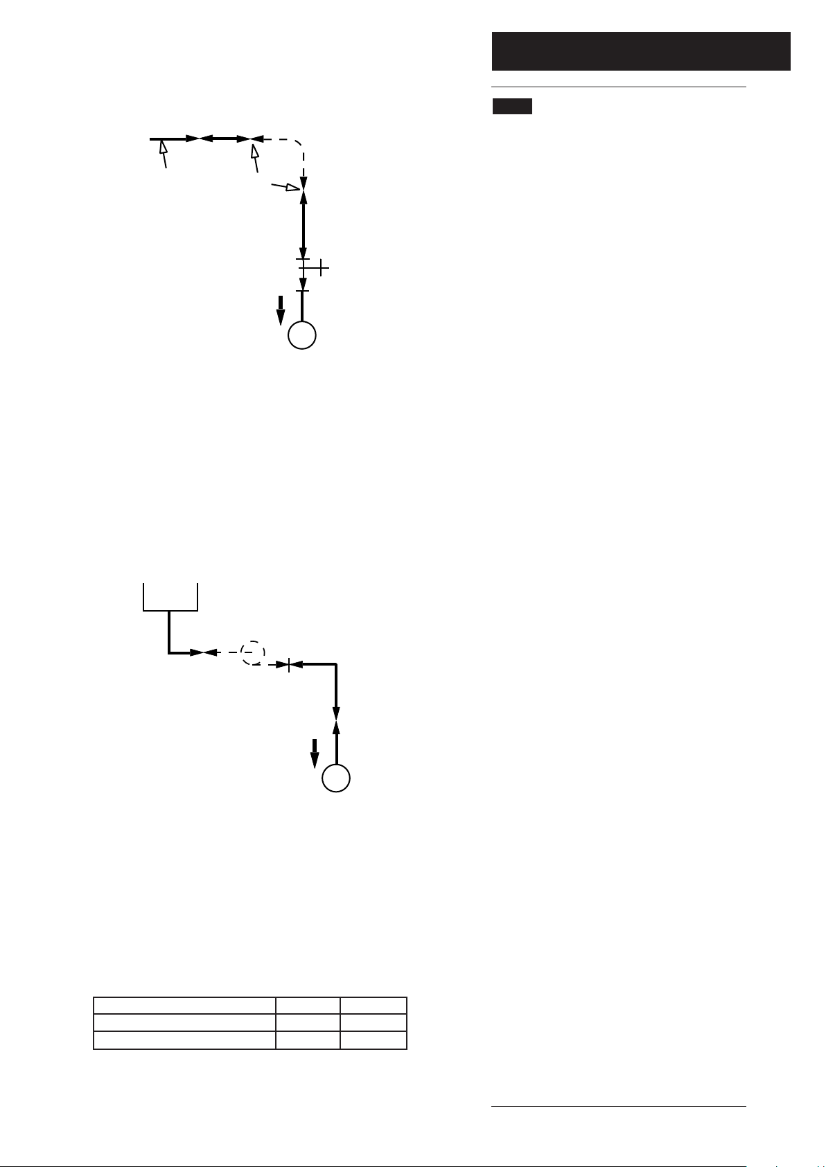
5.10 Condensate Disposal (Fig. 12)
1. This boiler incorporates an automatic pumped condensate
system. The pump is submerged in a sump assembly and is
activated by the discharge float switch. A second (safety) float
switch is fitted.
2. The pump has an effective head of 3.5 metres. The
condensate outlet is positioned at the top right front of the
boiler. It is 10mm diameter plastic.
3. 3.5 metres of flexible 10mm condensate discharge pipe and a
10mm push fit elbow are supplied with the boiler.
4. The 10mm pipe can be routed to a maximum of 3.5 metres
vertically and then discharge via gravity or be routed
horizontally. A combination of vertical and horizontal runs is
permissible.
5. The pipe must be adequately supported, either using suitably
spaced clips or run within larger diameter pipe. When using clips
take care not to deform the pipe.
6. When routing the pipe through a wall it must be suitably
sleeved. Also the pipe must not be exposed to sources of heat,
and should be protected in locations where it may be damaged.
7. The pipe should be routed so that any sharp bends, dips and
loops are avoided. A minimum radius of 100mm is
recommended for any bends. No slope is necessary and air
breaks are not required on the pumped part of the condensate
run.
8. Any part of the condensate drain system that is outside the
dwelling, or in an unheated part of it must be at least 21.5mm
diameter.
Boiler
Max. Head
3.5 metres
Gravity Drain
min. fall 3°
Min. radius 100mm
Note: The point of discharge from the
pumped length of condensate pipe
(point ‘A’) must be 150mm above the
base level of the boiler, whether
discharging direct into a drain or into
an additional gravity drain.
Point ‘A’
Fig. 12
Page 19

19
© Baxi Heating UK Ltd 2009
5.0 Site Requirements
5.10 Condensate Disposal (cont.)
9. Ensure that the condensate can discharge freely (without
blockage or restriction of the pipe) into the drain.
10. Examples are shown of condensate pipe methods of
termination:-
i) via an internal discharge branch
(e.g. sink waste) - Fig. 13.
ii) to an internal or external soil and vent pipe -
Fig. 14.
iii) to a drain or gully - Fig. 15. Ensure that the
condensate can discharge freely (without
blockage or restriction of the pipe) into the
drain.
iv) to a soakaway - Fig. 16.
5.11 Condensate Pump Operation
1. The pump operates for 2 seconds when mains voltage is
applied to the boiler, e.g. when the power has been
interrupted and then reinstated.
2. If the boiler reset rocker switch has been operated the
pump will run also for 2 seconds.
3. When the level of condensate in the sump is sufficient to
activate the discharge float switch the pump will run for 7
seconds, during which time about 0.6 litres of condensate will
be discharged.
4. In the event of condensate not being discharged the safety
float switch will operate when the volume of condensate in
the sump reaches 1.05 litres. Once the safety float switch has
been activated the boiler will lockout.
5. The total volume of the sump is 1.5 litres.
From Boiler
Termination to an internal soil and vent pipe
Termination via internal discharge branch e.g
sink waste - downstream
Sink
Pipe must terminate
above water level but
below surrounding surface
Pipe must terminate above
water level but below
surrounding surface
Termination to a drain or gully
Termination to a purpose made
soak-away
Holes in the soak-away must
face away from the building
Fig. 13
Fig. 14
Fig. 15
Fig. 16
Direct Connect Fitting
Direct Connect Fitting
From Boiler
From Boiler
From Boiler
Min. 450mm
500mm Min.
Page 20

20
© Baxi Heating UK Ltd 2009
6.0 Boiler Internal Wiring
6.1 Boiler Internal Illustrated Wiring Diagram
Discharge Float
Switch
bk
Safety Float
bk
bk
Switch
bk
bk
bk
Central Heating
NTC Flow Sensor
gr
gr
gr
gr
Overheat Thermostat
b
r
1
4
2
br
bk
5
b
g
b
br
3
1
2
g/y
Fan
X900
X300
X400
9876
54321
910 8 7 6
Control PCB
X501
X500
12
X1
br
ON/OFF
br
b
Reset
br
3
N
2
1
X2 X3
b
bk
b
br
b
br
Spark
Generator
1212 3344
br
b
b
54321
a
X401
556789
b
bk
bk
br
r
1234
X9
y
b
b
Condensate Pump
bk
bk
r
bk
b
y
3
N
2
1
Mains Input
(Permanent Live to 3,
Switched Live to 1)
r
Ignition
Electrode
b
y
- green
br
bk
b
w
y
- brown
- black
- blue
- white
- yellow
g
- green / yellow
g/y
- red
r
- greygr
Gas Valve
Page 21

7.0 Installation
21
© Baxi Heating UK Ltd 2009
INSTALLATION SEQUENCE
There are 4 main elements to the installation of the
Baxi Bermuda BBU 15 HE:-
• Preparation of pipework & opening
• Inserting the flue into the chimney
• Siting & fixing the boiler
• Fitting the terminal assembly
The sequence in which these are performed may
depend upon various factors beyond the scope of
these instructions. The above list is intended as a
guide based on a typical installation.
It is not necessary to open the firefront pack until
the boiler and flue are installed, and the boiler is
ready to be commissioned. The firefront pack
includes full instructions.
7.1 Initial Preparation
1. Remove the outer carton from the boiler pack.
Discard the packing pieces and remove the fitting kit.
2. Ensure that the base of the builders opening is clean
and level.
3. Complete any pipework installation and routing of
electrical cables within the builders opening that may be
difficult once the boiler is in place.
7.2 Flue System
1. The actual length of flue (as opposed to the vertical
distance from the boiler top to the chimney outlet)
MUST be established before commencing.
2. The flue must have a minimum vertical height of 3m
and have no bends greater than 45°.
NO HORIZONTAL RUNSARE PERMITTED !
3. Depending on the actual flue length it may be
beneficial to shorten the flue at this point to enable
easier handling.
4. Take one of the 60mm lip seals supplied and fit to
the first groove in the flue duct. Also fit the 100mm lip
seal to the air duct. (Figs. 17 & 18).
NOTE: Talcum powder may be used to ease fitting
of the adaptors over the seals. DO NOT use oil,
grease or soap.
5. Unfasten the clips on the boiler adaptor and insert
the end of the flue duct with the seal into the 60mm
socket. Ensure the seal is positioned past the clips, then
engage the clips over the larger diameter ‘rib’ on the
duct (Fig. 19).
6. Repeat the process for the 100mm air duct (Fig. 20)
Fig. 17
Fig. 18
Fig. 19
Fig. 20
Page 22

7.0 Installation
22
© Baxi Heating UK Ltd 2009
7.2 Flue System (cont.)
8. It is recommended that the Pull Cone Flue Adaptor
(part no. 720111801) is used as shown to ease the
fitting of the flue into the chimney and prevent damage
to the adaptor.
9. The cone has two internal lugs that engage on the
boiler adaptor in a bayonet action (Figs. 21 & 22).
10. A suitable weight should then be tied to the guide
rope fixed to the cone. The weight can then be passed
into the chimney and will draw the guide rope down
(Fig. 23).
11. Once the Pull Cone is visible in the builders opening
it can be removed. It can be re-used indefinitely on
other installations.
Note: It is recommended that the boiler is installed
at this point. See Sections 8.3 to 8.7
12. Remove the plastic plug from the boiler flue outlet.
Grasp the adaptor and locate it into the boiler, ensuring
the two large barbs lock into position under the boiler
top panel (Fig. 24) Fit the ‘C’ clip to the adaptor to
secure the flue. It must fit into the barbs and clip
securely into place (Fig. 24a).
13. There will now be an excess of flue and air duct
protruding from the chimney.
14. Cut the excess concentric ducts to leave
approximately 300 to 500mm protrudung from the
chimney and pass the square closure plate over the air
duct (Figs. 25 & 26).
15. Cut the 100mm air duct ONLY that 5 ‘ribs’ are
above the level of the chimney, taking care not to
damage the 60mm flue duct.
16. In a similar way to fitting the boiler adaptor fit the
air duct clamp to the air duct. This will prevent the duct
falling back into the chimney (Fig. 27).
Fig. 21
Fig. 22
Fig. 23
Fig. 24
Fig. 25
Fig. 26
Fig. 27
Cut to leave
5 ribs visible
Remove plug
from here
Fig. 24a
Barb
NOTE: These seals
factory lubricated
‘C’ Clip
Page 23

7.0 Installation
23
© Baxi Heating UK Ltd 2009
7.2 Flue System (cont.)
16. Pass the air duct collar and air cowl over the 60mm
flue duct (Fig. 28) and secure the collar to the closure
plate with the screws supplied (Fig. 29). The air cowl
will fit snugly over the collar.
17. Cut the protruding 60mm flue duct down so that 5
ribs are visible and fit the remaining 60mm lip seal into
the first groove (Fig. 30). The flue duct adaptor can
now be fitted in the same manner as the boiler adaptor
(Fig. 31).
18. Fit the terminal cap over the flue duct adaptor and
air cowl. Once the cap is clipped into position it cannot
be removed easily without damage (Fig. 33).
19. Cement over the closure plate and air duct collar to
a depth of approximately 100mm. Consideration should
be given to the potential accumulation of snow in this
area, and the possibility of it blocking the air inlet
(Fig. 34).
Fig. 30
Fig. 28
Air Duct
Collar
Air Cowl
Fig. 29
Fig. 31
Fig. 32
Fig. 33
Fig. 34
Terminal
Cap
Cement around
Air Duct Collar
& Cowl
5 ribs
Page 24

7.0 Installation
24
© Baxi Heating UK Ltd 2009
7.3 Siting the Boiler
IMPORTANT - This product should be lifted and
handled by two people. Stooping should be avoided and
protective equipment worn where necessary. Carrying
& lifting equipment should be used as required, e.g.
when installing on another floor.
1. Lift the boiler from the packing base and place into the
opening.
2. Align the boiler centrally as far back in the opening as
possible, and ensure the distance between each side and
the opening is equal. Check that the boiler is level.
3. Mark the hearth through two of the slots in the base
(Fig. 35). Remove the boiler and drill the hearth. Insert
suitable plugs. Replace the boiler & check the alignment
within the opening. Secure the boiler with suitable screws.
7.4 Water Connections
1. The boiler has one return and one flow connection. The
flow is the upper connection. It is essential the flow and
return pipes are connected correctly (Fig. 36).
7.5 Gas Connection
1. Connection to the gas supply is a 15mm compression
fitting on the gas cock. The gas supply pipe must be routed
from the right hand side.
2. The positioning of the gas supply pipe must not restrict
the servicing of the boiler or installation of the firefront.
7.6 Electrical Connection
1. The boiler requires an electrical supply from the heating
controls system.
WARNING: The appliance must be earthed.
The input cable for the appliance should be 0.75mm
2
to
IEC Code 227 (heat resistant). The system external
controls and the boiler must be supplied by the same
isolator.
The boiler MUST NOT be connected to the
same supply as the firefront as their fuse ratings are
different.
7.7 Making the Electrical Connection
1. Take the 5 pin plug from the boiler fitting kit, remove
the securing screws and hinge the cover open.
2. Route the mains inlet cable under the cable clamp and
connect Permanent Live, Neutral & Earth to 3, N &
respectively. Ensure that the Earth lead is longest.
3. Connect the switched output from the system external
control system to terminal 1.
4. Refit the cover, tighten the screws to secure the cable
and connect the plug to the one on the boiler.
Fixing Slot
Condensate
Discharge (remove
plug before connection)
Return
Flow
1
2
N
3
Fig. 35
Fig. 36
Fig. 37
Page 25

25
© Baxi Heating UK Ltd 2009
8.0 Completion & Commissioning
8.1 Completion
1. Seal off any secondary openings within the builders
opening after wrapping the gas and water pipes through the
brickwork and within the opening itself. (B.S. 5871 Part 1).
2. Take the Boiler Control from the firefront packaging and
connect it to the boiler (Fig. 38).
8.2
Commissioning the Boiler
1. Reference should be made to BS 5449 Section 5 when
commissioning the boiler.
2. At the time of commissioning, complete all relevant
sections of the Benchmark Checklist at the rear of this
publication.
IMPORTANT: The heat exchanger air vent on top of the
boiler (Fig. 38) MUST be opened before filling the
primary system.
3. Ensure all valves in the water system are turned on.
4. The system must be flushed in accordance with BS 7593
(see Section 5.2) and the flushing agent manufacturers
instructions.
5. Turn the gas supply on and purge according to in GB BS
6891 and in IE I.S. 813 "Domestic Gas Installations".
6. Test for gas soundness.
7. Ensure all external controls e.g. room stat, timer etc. are
calling for heat and turn on the mains electrical supply. Turn
the rocker switch at the top right of the boiler to ON. The
fan and condensate pump will run briefly.
8. The display will count down from 7 to 0, then the current
water temperature will be displayed.
9. When there is a demand for heating the bar on the top
left of the display will be shown and the boiler will
commence the ignition sequence.
10. When ignition is established the ‘flame’ symbol on the
display is illuminated. The display will indicate the flow
temperature. The appliance is fully preset, therefore no
adjustment is required.
11. If the boiler fails to ignite within the three ignition
attempts the error code E133 will appear in the display, ‘E1’
alternating with ‘33’.
12. To reset the boiler press the reset button for at least 3
seconds. The ignition sequence will then recommence. A
maximum of four resets in a five hour period are allowed.
13. When the reset button is activated the number of
available reset attempts will be displayed
Auto Air
Vent
ON/OFF
Fig. 38
Fig. 39
Fig. 40
Service
Reset
Countdown
Current Temp.
& Demand
Burner Lit
Remaining
Resets
Page 26

26
© Baxi Heating UK Ltd 2009
8.0 Completion & Commissioning
8.2 Commissioning the Boiler (cont.)
IMPORTANT: The combustion for this appliance has
been checked, adjusted and preset at the factory for
operation on the gas type specified on the appliance data
plate. No measurement of the combustion is necessary.
Do not adjust the air/gas ratio valve.
Having checked:
That the boiler has been installed in accordance with
these instructions.
The integrity of the flue system and the flue seals, as
described in Section 7.2.
Proceed to put the boiler into operation as follows:
Check the Operational Gas Inlet Pressure
14. Set the boiler to operate at maximum rate as
described in Section 11.1.2 to 11.1.6.
15. With the boiler operating in the maximum rate
condition check that the operational gas pressure at the
inlet gas pressure test point is 20mb (Fig. 40a).
16. Ensure that this inlet pressure can be obtained with
all other gas appliances in the property working.
Measure the Gas Rate
17. With any other appliances & pilot lights turned OFF
the gas rate can be measured. It should be between 1.55
and 1.71m
3
/h.
18. Carefully read and complete all sections of the
Benchmark Commissioning Checklist at the rear of this
publication that are relevant to the boiler and installation.
These details will be required in the event of any
warranty work. The publication must be handed to the
user for safe keeping and each subsequent regular service
visit recorded.
For IE, it is necessary to complete a “Declaration of
Conformity” to indicate compliance with I.S. 813. An
example of this is given in I.S. 813 “Domestic Gas
Installations”. This is in addition to the Benchmark
Commissioning Checklist.
19. Disconnect the Boiler Control and fit the firefront in
accordance with the instructions supplied with it.
IMPORTANT: The loose boiler serial number label
supplied in the boiler kit must be applied to an area of
the spacer frame that is visible to the end user e.g.
lower right hand side.
Inlet Gas Pressure
Test Point
Fig. 40a
Page 27

27
© Baxi Heating UK Ltd 2009
9.0 Annual Servicing
Off Position
Fig. 41
On Position
Fig. 42
9.1 Annual Servicing
1. For reasons of safety and economy, it is recommended that
the boiler is serviced annually. Servicing must be performed by
a competent person in accordance with B.S. 7967-4.
2. After servicing, complete the relevant Service Interval
Record section of the Benchmark Commissioning Checklist at
the rear of this publication.
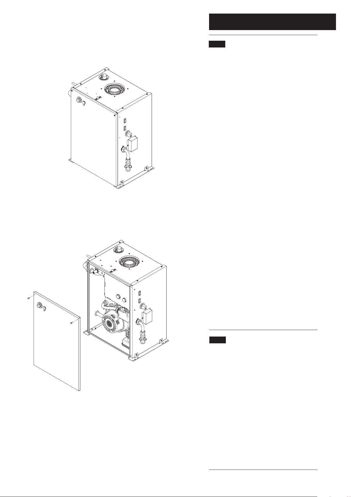
3. Disconnect the firefront electric supply. Remove the fascia
from the firefront. Unhook its hanging brackets from the slots
in the top of the firefront. On Classica and Innova models also
disengage the retaining magnets at the lower part of the fascia.
4. Slacken the firefront retaining wire and unthread it from the
bracket on top of the boiler. The firefront can now be
manoeuvred away from the boiler. Do not drag the firefront
as it may damage the hearth. To completely remove the
firefront disconnect the boiler control cable.
IMPORTANT: During routine servicing, and after any
maintenance or change of part of the combustion circuit, the
following must be checked:-
The integrity of the flue system and the flue seals, as
described in Section 7.2.
The integrity of the boiler combustion circuit and relevant
seals as described in Section 9.2.
The operational gas inlet pressure as described in Section
8.2.14 to 8.2.16 and the gas rate as described in 8.2.17.
The combustion performance as described in 9.1.5 to 9.1.6.
Competence to carry out checking Combustion
Performance
B.S. 6798 ‘Specification for Installation & Maintenance of Gas
Fired Boilers not exceeding 70kW’ advises that:-
The person carrying out a combustion measurement
should have been assessed as competent in the use of a
flue gas analyser and the interpretation of the results.
The flue gas analyser used should be one meeting the
requirements of BS7927 or BS-EN50379-3 and be
calibrated in accordance with the analyser manufacturers’
requirements.
Competence can be demonstrated by satisfactory
completion of the CPA1 ACS assessment, which covers
the use of electronic portable combustion gas analysers in
accordance with BS 7967, Parts 1 to 4.
Check the Combustion Performance
5. Set the boiler to operate at maximum rate as described in
Section 11.1.2 to 11.1.6.
6. Remove the threaded plug from the sampling point, insert
the analyser probe and obtain the CO/CO
2
ratio. This must
be less than 0.004.
7. If the combustion reading is greater than this, and the
integrity of the flue system and combustion circuit seals has
been verified, and the inlet gas pressure and gas rate are
satisfactory either adjust the gas valve (Section 11.0), replace
the gas valve (Section 10.8) or contact the ‘heateam’ Technical
Helpline (0844 871 1555).
Flue Sampling
Plug
Page 28

28
© Baxi Heating UK Ltd 2009
9.0 Annual Servicing
9.2 Annual Servicing - Inspection
1. Ensure that the boiler is cool.
2. Ensure that the gas supply to the boiler is isolated.
3. Operate the Reset switch (Fig. 41) to activate the
condensate pump and then repeat. This will empty most of
the condensate from the sump.9. Isolate the boiler from the
electrical supply.
4. Undo & remove the flue sampling plug and washer. Remove
the screws retaining the boiler front panel, and lift the panel
away (Fig. 43).
5. Remove the screw securing the PCB control box and swing
the box to the right (Fig. 43).
6. Disconnect the two plugs from the fan motor and remove
the sensing pipe from between the gas valve and fan outlet.
7. Remove the gas feed pipe and washers, and extract the
injector from the gas/air inlet manifold.
8. For ease of access disconnect the following:a) 2 pin plug on NTC lead
b) all wires from electrode assembly
c) all wires from spark generator
d) both wires from the overheat thermostat
e) the red and black wires connected together
9. Undo the two securing nuts and remove the spark
generator and bracket.
10. Undo the combustion panel securing nuts and remove the
special spring washers. Remove the complete fan & panel
assembly from the boiler.
11. Lay the assembly to one side. The outer insulation panel is
fitted to the rear of the combustion box panel.
12. Clean inside the heat exchanger and examine the
condition of the fins.
13. Examine the burner, electrodes, insulation and seal,
replacing if necessary. Also check the condition of the three
insulation pieces in the rear of the heat exchanger.
14. Disconnect the wires on the condensate pump motor and
pull off the plastic discharge pipe. Cut and remove the transit
cable tie. It is not necessary to replace this item.
15. Squeeze the two retaining clips and turn the pump
anticlockwise to remove it. Draw it upwards from the sump.
16. Clean any debris from the sump and examine the
condition of the pump seal, replacing if necessary.
17. Reassemble in reverse order of dismantling, checking and
replacing any components as necessary. Recommission the
boiler and complete the relevant Service Interval Record
section of the Benchmark Commissioning Checklist at the rear
of this publication.
Fig. 43
PCB Control
Box
PCB Control Box
Securing Screw
Locking Clip
Condensate Pump
Discharge Pipe
Fig. 44
Boiler Front
Panel
Spark
Generator
Electrode
Assembly
Injector
Sensing Pipe
Gas Valve
Gas Feed
Pipe
Fan
Reset Switch
Off Position
Page 29

29
© Baxi Heating UK Ltd 2009
10.0 Changing Components
10.1 Changing Components
1. To change any components on the back boiler it is
necessary to remove the firefront.
2. Refer to the Installer Guide that accompanies the
firefront for details of removal.
3. Ensure that the boiler is cool and that the electrical
and gas supplies are isolated.
4. After changing any components carry out gas
soundness checks.
5. Undo & remove the flue sampling plug and washer.
Remove the screws retaining the boiler front panel, and
lift the panel away.
6. Remove the screw securing the PCB control box and
swing the box to the right.
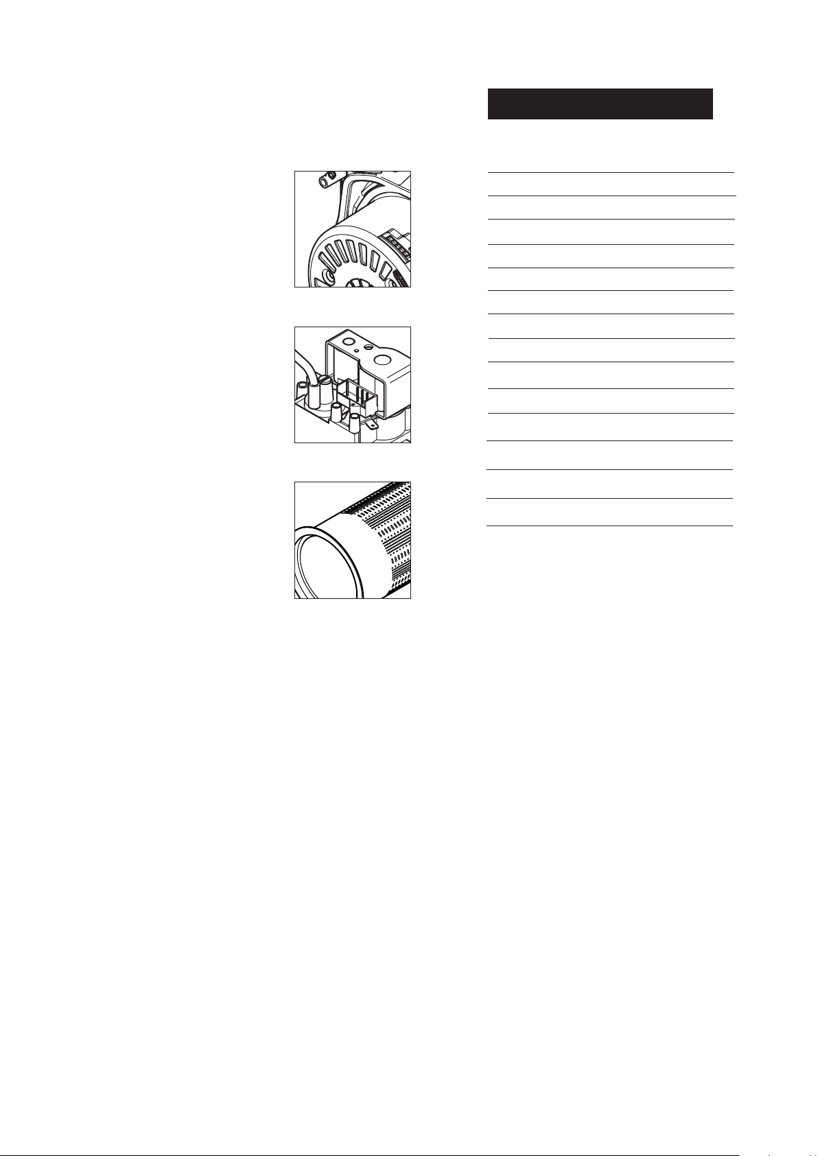
10.2 Spark Generator (Fig. 46)
1. Note the position of the two leads on the spark
generator and disconnect them. Also disconnect the
earth wire and plug, and remove the screws securing the
spark generator to the bracket.
2. Remove the spark generator. Replace in reverse order
of dismantling, using the screws previously removed.
3. Ensure that the leads and plug are pushed fully on to
their terminals.
10.3 Electrode Assembly (Fig. 47)
1. Note the position of the two leads on the electrode
assembly and disconnect them. Disconnect the in-line
connection on the black wire and the earth wire.
2. Undo the securing screws and remove the electrode
assembly and earth tag from the combustion box panel.
3. Replace in reverse order of dismantling, using the
screws previously removed. Examine the sealing gasket
and replace if necessary.
4. Ensure that the leads are pushed fully on to their
terminals.
10.4 Condensate Pump (Fig.48)
1. Note the position of the two leads and earth wire on
the pump motor and disconnect them.
2. Cut and remove the transit cable tie. It is not
necessary to replace this item.
3. Squeeze in the two locking clips and turn the pump
anti-clockwise. Pull the condensate discharge pipe off its
connection and remove the pump.
4. Replace in reverse order of dismantling. Examine the
sealing ring and replace if necessary.
5. Ensure that the leads are pushed fully on to their
terminals.
PCB Control Box
removed for clarity
Spark Generator
Plug
Electrode
Sealing Gasket
Locking Clip
Condensate Pump
Fig. 45
Fig. 46
Fig. 47
Fig. 48
Page 30

30
© Baxi Heating UK Ltd 2009
10.5 Fan (Fig. 49)
1. Disconnect the two plugs from the fan motor and
remove the sensing pipe from between the gas valve
and fan outlet.
2. Remove the gas feed pipe and washers, and extract
the injector from the gas/air inlet manifold.
3. For ease of access disconnect the following:a) 2 pin plug on NTC lead
b) all wires from electrode assembly
c) all wires from spark generator
d) both wires from the overheat thermostat
e) the red and black wires connected together
4. Undo the two securing nuts and remove the spark
generator and bracket.
5. Undo the combustion panel securing nuts and remove
the special spring washers. Remove the complete fan &
panel assembly from the boiler. Check the condition of
the insulation piece.
6. Undo and remove the nuts and washers securing the
fan to the gas/air inlet. NOTE THE POSITION OF THE
RESTRICTOR PLATE !
7. Remove the securing screws and transfer the fan inlet
to the new fan. Use a new sealing gasket if necessary.
8. Replace in reverse order. ENSURE THAT THE
RESTRICTOR PLATE IS CORRECTLY FITTED ! THE
SLOT MUST BE TO THE REAR. Check the condition of
the sealing gaskets between the fan and gas/air inlet and
the combustion panel and heat exchanger and replace if
necessary.
10.6 Burner (Fig. 50)
1. Proceed as described in points 1. to 5. above.
2. Undo the screws securing the burner to the
combustion panel. Remove the burner.
3. Replace in reverse order of dismantling, using the
screws previously removed. Examine the sealing gasket
and replace if necessary.
10.7 Injector (Fig. 50)
1. Remove the gas feed pipe and washers, and extract
the injector from the gas/air inlet manifold.
2. Replace in reverse order of dismantling. Examine the
sealing washers and replace if necessary.
10.0 Changing Components
PCB Control Box
removed for clarity
Burner
Injector
Injector
Spark Generator
Plug
Fan
Spark Generator
Plug
Electrode
Fig. 49
Fig. 50
Note position
of Slot
Gas Feed
Pipe
Page 31
31
© Baxi Heating UK Ltd 2009
10.0 Changing Components
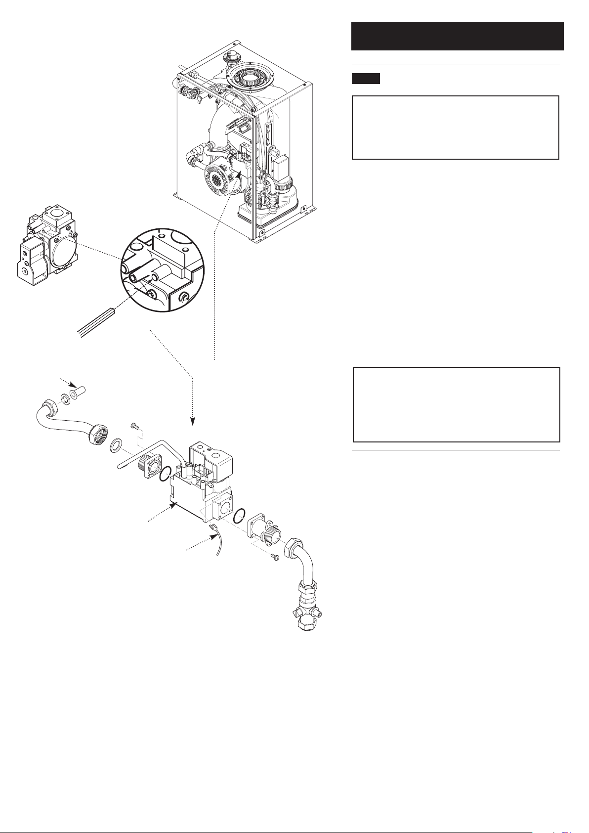
10.8 Gas Valve (Fig. 51)
IMPORTANT: After replacing the valve the CO2must be
checked and adjusted as detailed in Section 11.0 Setting
the Gas Valve. Only change the valve if a suitable
calibrated combustion analyser is available, operated by a
competent person - see Section 9.1
1. Disconnect the plug and earth wire from the gas valve and
remove the sensing pipe from between the valve and fan
outlet.
2. Remove the gas feed pipe and washers, and extract the
injector from the gas/air inlet manifold.
3. Undo the nut on the pipe from the gas cock to the valve
inlet adaptor, and remove the screws securing the adaptor to
the boiler side panel.
4. Remove the valve complete with the inlet and outlet
adaptors, and the seal on the inner face of the side panel.
Transfer the adaptors to the new valve, using new ‘O’ rings if
necessary.
5. Replace in reverse order of dismantling, using the screws
previously removed. Examine all sealing gaskets and washers
and replace if necessary.
NOTE: To assist the boiler to light prior to final setting,
use a suitable hexagon key to wind out the Gas/Air
adjustment screw until it is flush with the valve body, then
turn the screw 4 full turns clockwise (Fig. 51). If the boiler
will not light, or the correct CO
2
cannot be achieved
contact the ‘heateam’ technical helpline.
PCB Control Box
removed for clarity
Gas Valve
Earth Wire
Injector
Fig. 51
Page 32

32
© Baxi Heating UK Ltd 2009
10.9 PCB (Fig. 54)
1. Pull off the two control knobs and disengage the
securing tabs of the cover. Undo the screws securing the
PCB.
2. Draw the PCB forwards and disconnect the wiring.
Transfer the two potentiometer drive pins to the new
PCB and replace in reverse order of dismantling.
3. Ensure that the wiring connectors are pushed fully on
to the PCB terminals.
10.10 NTC (Fig. 53)
1. Disconnect the 2 pin plug. Remove the clip retaining
the NTC in the heat exchanger pocket. Pull the NTC
out of the pocket.
2. Apply suitable heat transfer paste to the new NTC.
Replace in reverse order of dismantling, using the clip
previously removed. Ensure that the plug is fully engaged.
10.11 Safety Thermostat (Fig. 52)
1. Disconnect the two leads from the thermostat.
2. Remove the screws securing the thermostat to the
mounting plate on the flow pipe.
3. Replace in reverse order. The thermostat is not
polarised - either wire can fit either terminal on the
thermostat.
10.12 Float Switches (Fig. 55)
1. Remove the fan as described in Section 10.5,
paragraphs 1 to 5.
2. The two float switches are the same, but oriented
differently. The discharge switch is at the left, the safety
at the right.
3. To remove either switch disconnect the lead and pull
off the alignment bracket.
4. Undo the retaining nut. The sealing grommet will be
released from the sump body and allow the switch to be
removed.
5. Note the orientation of the alignment rib on the
switch. It is positioned uppermost on the safety float
switch and to the bottom on the discharge switch.
6. Take the new switch assembly and insert it into the
sump. Hand tighten the nut and slide the alignment
bracket in place to ensure the switch is in position.
Tighten the nut a further 2 turns.
7. Reconnect the lead to the switch, ensuring it is fully
engaged.
10.0 Changing Components
Discharge
Float Switch
Safety Float
Switch
PCB
Control Knobs
Safety Thermostat
Flow Pipe
Clip
NTC
Fig. 52
Fig. 53
Fig. 54
Fig. 55
Alignment
Bracket
Page 33

33
© Baxi Heating UK Ltd 2009
11.0 Setting the Gas Valve
11.1 Setting the Gas Valve (CO
2
check)
IMPORTANT: The CO
2
must be only be checked and
adjusted to set the valve if a suitable calibrated
combustion analyser is available, operated by a
competent person - see Section 9.1
1. The combustion (CO
2
) may be checked after running the
boiler for several minutes. To do this it is necessary to set
the boiler to ‘Calibration Mode’.
2. Ensure that all external controls are calling for heat. The
actual current boiler temperature is shown on the display.
3. Turn both control knobs fully anticlockwise, then quickly
turn the right hand knob
1
/4clockwise twice and back fully
anticlockwise (Fig. 56).
4. The display will now alternate between ‘SF’ and the
current boiler temperature and both green LEDs will flash
(Figs. 57 & 58).
5. Turn the left hand knob fully clockwise. As the knob is
turned the display will change, indicating the fan speed.
6. The display will show ‘00’, indicating maximum rate, then
revert to ‘P ‘ alternating with the current boiler temperature
(Figs. 59, 60 & 61 ).
7. Remove the plug from the flue sampling test point. Insert
the analyser probe and allow sufficient time for the reading
to settle (Fig. 56).
The CO
2
should be 9.3% ± 0.2
8. It is possible to alter the CO
2
by adjustment of the gas
valve. Remove the plastic cover from the ‘Max Rate’
adjustment screw. At maximum rate the ‘Max. Rate’
adjustment screw should be turned, using a suitable hexagon
key, until the correct reading is obtained (Fig. 62).
Turning clockwise will reduce the CO
2
. Anticlockwise will
increase the CO
2
.
9. The CO
2
must then be checked at minimum rate. Turn
the left hand knob fully anti-clockwise. As the knob is turned
the display will change, indicating the fan speed. When the
display reads ‘ 0’ the boiler runs at minimum rate.
The CO
2
should be 8.2% ± 0.2
10. With the boiler on minimum, the ‘Min. Rate’ adjustment
screw must be altered, using a suitable hexagon key, after
removing the cap (Fig. 62). Turning anti-clockwise will reduce
the CO
2
. Clockwise will increase the CO2.
11. The ‘Calibration Function’ is maintained for 20 minutes
unless the maximum CH temperature is exceeded. The
function can be disabled at any time by turning the right
hand knob.
12. Check the CO/CO
2
ratio. This must be less than 0.004.
Control
Knobs
Display
Flue Sampling
Point
Max Rate
Adjustment Screw
(cover removed)
Min Rate
Adjustment Screw
(cap fitted)
Fig. 56
Fig. 57
Fig. 58
Fig. 59
Fig. 60
Fig. 61
Fig. 62
Reduce CO
2
at min. rate
Increase CO
2
at min. rate
Reduce CO
2
at max. rate
Increase CO
2
at max. rate
If the CO
2
is reset at minimum rate it must
be rechecked at maximum rate again and
adjusted if required. If the CO
2
is reset at
maximum rate it must be rechecked at
minimum rate and adjusted if required.
Page 34

34
© Baxi Heating UK Ltd 2009
12.0 Fault Finding
NOTE: When instructed to
operate the reset button, press
and hold for 5 seconds to reset
the boiler.
12.1 Initial Fault Finding Checks
1. Check that gas, water and electrical supplies are available
at the boiler.
2. Electrical supply = 230V ~ 50 Hz. Check the CH & DHW
system. The preferred minimum gas pressure is 20 mbar.
3. Carry out electrical system checks, i.e. Earth Continuity,
Resistance to Earth, Short Circuit and Polarity with a suitable
meter.
NOTE: These checks must be repeated after any
servicing or fault finding.
4. Ensure all external controls are calling for heat and check
all external and internal fuses. Before any servicing or
replacement of parts, ensure the gas and electrical supplies
are isolated.
12.2 Error Codes
1. If a fault occurs on the boiler an error code may be shown
on the boiler display and the Boiler Control.
2. The codes are either two or three digit, preceded by the
letter 'E'. For example, code E133 will be displayed by 'E1'
alternating with '33'. E20 is shown as 'E' then '20'
E20 & E28 indicate faulty or incorrect components.
E110 shows overheat of the primary water or excess
condensate in the sump.
E125 is displayed if within 2 hours of the burner lighting the
boiler temperature twice exceeds the selected temperature
by 25°.
In these instances poor primary circulation or no water in the
system is indicated.
E133 indicates that the gas supply has been interrupted,
ignition has failed or the flame has not been detected.
E155 indicates a Boiler Control reset when Service & Boiler
Control reset counters are out of step. Boiler Control default
not restored correctly.
E158 indicates a condensate discharge system fault.
3. By pressing the 'Reset' button on the Boiler Control for a
minimum of 5 seconds when E110 & E133 are displayed it is
possible to relight the boiler.
4. If this does not have any effect, or the codes are displayed
regularly further investigation is required. It is possible to
reset the boiler up to 4 times in any 5 hour period. Further
resets via the Boiler Control are then blocked for 5 hours
unless a Service Reset is performed.
Central Heating NTC Fault
Incorrect PCB Fitted
Hot Water NTC Fault
Safety Thermostat or Condensate Safety Float Switch Operated
Circulation Fault (Primary Circuit)
Interruption Of Power Supply while in fault mode
Interruption Of Gas Supply or Flame Failure
Lock Out of Boiler Control
Condensate Discharge System Fault
Fan or Fan Wiring Fault
E20
E28
E50
E110
E125
E131
E133
E155
E158
E160
Table Of Error Codes
To perform a Service Reset it is necessary to have access to the boiler.
By pressing the Reset rocker switch on the right of the boiler case for a
minimum of 5 seconds when error codes are displayed it is possible to
reset the boiler once the fault has been rectified.
Service Reset
Following a Service Reset it is necessary to restore the Boiler Control to
default condition:-
Disconnect the main power supply
On reinstating the power supply the Boiler Control display will count
down from 7.
Before the count reaches 3 press both the ‘On/Off’ and ‘Reset’ buttons
simultaneously and hold until the count reaches 0.
The Boiler Control display will show ‘SEt’ to confirm default restoration.
Restoring Boiler Control Default
Page 35

12.0 Fault Finding
35
© Baxi Heating UK Ltd 2009
Refer to Section 16.0 “Illustrated Wiring Diagram” for position of terminals and components
Central Heating - Follow operational sequence
Turn on Power Supply
Display Illuminates
Error 20 or 28 flashing
Error 158 flashing
Burner lights
Error 110 flashing
Error 131 flashing
Turn Central Heating
thermostat to Maximum.
Pump runs
Fan runs
Spark at ignition electrodes for
up to 5 seconds and for 3
attempts
Error 155 flashing
Go to section ‘A’
Go to section ‘E’
Ensure all external controls
are calling for heat
Go to section ‘J’
Go to section ‘B’
Error 160 flashing
Go to section ‘D’
Error 133 flashing
Burner does not stay alights
after 5 seconds
Error 133 flashing
Go to section ‘H’
Operation sequence
successful
If the error 110 is still flashing.
Go to section ‘I’
Fan runs at correct speed
YES
YES
NO
NO
NO
YES
YES
YES
YES
YES
YES YES
YES
NO
YES YES
YES
YES
NO
NO
NO
NO
NO
Burner output modulates to
maintain the temperature set
Burner goes out
Go to section ‘C’
Ensure controls are set to
demand and verify the
contacts are closed
Error 160 flashing
Go to section ‘K’
YES
Go to section ‘G’
Turn the selector switch to
reset
Go to section ‘F’
YES
Check the Central Heating
NTC sensor
Go to section ‘E’
Fan stops after 10 seconds
Burner relights after at least 3
minutes, when the display is
less than the set temperature
(room thermostat open)
NO
NO
YES
NO
YES
YES
Press the Service Reset
switch for 5 seconds
NO
Error 125 flashing
Ensure that the system is full,
primary circulation is OK &
that there is no blockage
YES
Go to section ‘J’
NOTE: Sections ‘A’ to ‘L’
referred to in the chart
opposite are on the
following pages
Page 36

12.0 Fault Finding
36
© Baxi Heating UK Ltd 2009
Fault Finding Solutions Sections
Is there 230V at:
Check all system wiring and pump
Main terminals L and N Check electrical supply
1.
NO
Main terminal fuse
Replace fuse
Replace PCB
Display
illuminated
2.
NO
PCB - X1 connector
terminals 1,2
Check wiring
3.
NO
NO
A
B
1.
2.
C
NO
YES
Fan connections correct at fan. PCB X2 connector, is 230V AC across
terminals 5 & 7
Fan jammed or faulty winding
Replace PCB
Replace fan
YES
D
E20 - Temperature sensor faulty.
Cold resistance approximately
10kΩ @ 25° C
(resistance reduces with increase in temp.)
E28 - Incorrect PCB fitted
NO
E
Replace sensor or PCB (E28)
Gas at burner
Ensure gas is on and purged
Replace PCB
Replace gas valve
PCB - X3 connector is 230V AC across
terminals 1 & 2
YES
NO
NO
F
Check and correct the connection of the
tube between the venturi and gas valve
1.
2.
Service Reset
Condensate Pump does not run On Reset is there 230V at:
PCB - X3 connector terminals 5 &
6 for at least 2 seconds
Replace PCB
NO
Condensate Pump terminals for at
least 2 seconds
Replace wiring
NO
YES
Replace Cond. Pump
Condensate Pump runs
YES
Condensate drain system blocked
Replace Float Switch
Clean condensate drain system
Replace PCB
G
Check and correct if necessary
1. Ignition electrode and lead
2. Electrode connection
3. Spark gap and position
voltage at PCB - X2 connector is
110V AC across terminals 2 & 5
(Note: from multimeter connect
‘common’ to 2 & ‘volts’ to 5)
Check wiring
YES
NO
Replace igniter
YES
NO
YES
Page 37

12.0 Fault Finding
37
© Baxi Heating UK Ltd 2009
Check and correct if necessary
1. The mechanical set of the gas valve
(CO2 values - see instruction)
2. Flame sensing electrode and lead connections
3. Flame sensing electrode position
Flame current should be more than 0.5 μA
Replace PCB
YES
Replace flame sensing electrode
NO
Check the gas supply pressure:
For Natural Gas greater than
10 - 11 mbar
I
Replace Safety Thermostat
YES
Overheat Thermostat or
Condensate Safety Float Switch
operated or faulty
Allow to cool. Continuity
across thermostat terminals
more than 1.5 ohm
2.
1.
H
K
J
L
Press the Service Reset switch
for 5 seconds
Fan connections correct at fan.
PCB - X401 connector terminals 5,6,7 & 8
YES
Replace fan
Temperature sensors faulty.
Cold resistance approximately
10kΩ @ 25° C (CH sensor)
(resistance reduces with increase in temp.)
NO
Replace sensor
YES
If pump is running the heat exchanger could be
obstructed
Replace heat exchanger
1.
2.
Restore Boiler Control defaults
NO
Continuity across plug
terminals at 3 & 4 of connector
X401 more than1.5 ohm
Replace PCB
NO
YES
Condensate drain system fault
Check condensate system
and Pump
Replace Safety Float Switch
or wiring
NO
IMPORTANT:There is no limit to the number of repeated ‘Service Reset’
operations but the Boiler Control must be refreshed by ‘Restoring Boiler
Control Default’ as described on p.34 following the final ‘Service Reset’ and
before the Boiler Control reset is re-used.
YES
Page 38

38
© Baxi Heating UK Ltd 2009
13.0 Short Parts List
Short Parts List
Key Description Manufacturers
No. Part No.
A Burner Assy 720125701
B Injector 720126301
C Ignition Lead 720127501
D Gas Valve 720127001
E P.C.B 720125801
F Fan 5121447
G NTC Sensor 720126101
H Float Switch
(Safety or Discharge) 720126201
I Safety Thermostat 720126401
J Spark Generator 5114766
K Condensate Pump 720125901
H
I
A
G
E
B
F
D
K
J
C
Page 39

39
© Baxi Heating UK Ltd 2009
14.0 Notes
Page 40

40
© Baxi Heating UK Ltd 2009
14.0 Notes
Page 41

14.0 Notes
41
© Baxi Heating UK Ltd 2009
Page 42

GAS BOILER SYSTEM COMMISSIONING CHECKLIST
CONTROLS Tick the appropriate boxes
Time and Temperature Control to Heating Room Thermostat and Programmable Load/Weather Optimum Start
remiT/remmargorP
Room Thermostat Compensation Control
remiT/remmargorP dna tatsomrehT rednilyC retaW toH ot lortnoC erutarepmeT dna
emiT Combination Boiler
dettiF sevlaV enoZ gnitaeH Not Required
dettiF sevlaV enoZ retaW toH Not Required
dettiF sevlaV rotaida
R citatsomrehT Not Required
dettiF metsyS ot ssapyB citamotuA Not Required
dedivorP kcolretnI relioB
ALL SYSTEMS
The system has been fl seY snoitcurtsni s’rerutcafunam reliob dna 3957SB htiw ecnadrocca ni denaelc dna dehsu
What system cleaner was used?
What inhibitor was used? Quantity litres
CENTRAL HEATING MODE Measure and Record:
Gas Rate
m
3
/hr OR
ft
3
/hr
)elbacilppa fi( erusserP gnitarepO renruB
mbar OR Gas Inlet Pressure mbar
Central Heating Flow Temperature °C
Central Heating Return Temperature °C
COMBINATION BOILERS ONLY
Is the installation in a hard water area (above 200ppm)? Yes No
If yes, has a water scale reducer been fi tted? Yes No
What type of scale reducer has been fi tted?
DOMESTIC HOT WATER MODE Measure and Record:
etaR saG
m
3
RO rh/
ft
3
/hr
)etar mumixam ta( erusserP telnI saG RO rabm )etar mumixam ta( erusserP gnitarepO renruB mbar
erutarepmeT telnI retaW dloC °C
Hot water has been checked at all outlets Yes Temperature °C
etaR wolF retaW l/min
CONDENSING BOILERS ONLY
seY 8976SB/6455SB ro/dna snoitcurtsni s’rerutcafunam eht htiw ecnadrocca ni dellatsni neeb sah niard etasnednoc ehT
ALL INSTALLATIONS
OC gniwollof eht drocer ,rerutcafunam eht yb deriuqer fI
2
% OR CO ppm OR CO/CO2Ratio
seY snoitalugeR gnidliuB etairporppa eht htiw seilpmoc metsys retaw toh dna gnitaeh ehT
seY snoit
curtsni s’rerutcafunam eht htiw ecnadrocca ni denoissimmoc dna dellatsni neeb evah stcudorp detaicossa dna reliob ehT
seY remotsuc eht yb dootsrednu dna ot detartsnomed neeb evah slortnoc metsys dna rel
iob eht fo noitarepo ehT
The manufacturer’s literature, including Benchmark Checklist and Service Record, has been explained and left with the customer Yes
*
All installations in England and Wales must be notifi ed to Local Authority Building Control (LABC) either directly or through a Competent Persons Scheme.
A Building Regulations Compliance Certifi cate will then be issued to the customer.
©Heating and Hotwater Industry Council (HHIC) www.centralheating.co.uk
Commissioning Engineer’s Signature
Customer’s Signature
(To confi rm satisfactory demonstration and receipt of manufacturer’s literature)
This Commissioning Checklist is to be completed in full by the competent person who commissioned the boiler as a means of demonstrating
compliance with the appropriate Building Regulations and then handed to the customer to keep for future reference.
Failure to install and commission this equipment to the manufacturer’s instructions may invalidate the warranty but does not affect statutory rights.
Customer Name Telephone Number
Address
Boiler Make and Model
Boiler Serial Number
Commissioned by (print name)
Company Name Telephone Number
Gas Safe Register licence No.
Company Address
Commissioning Date
To be completed by the customer on receipt of a Building Regulations Compliance Certifi cate
*
:
Building Regulations Notifi cation Number (if applicable)
42
Page 43

SERVICE RECORD
It is recommended that your heating system is serviced regularly and that the appropriate Service Record is completed.
Service Provider
Before completing the appropriate Service Record below, please ensure you have carried out the service as described in the manufacturer’s
instructions.
Always use the manufacturer’s specifi ed spare part when replacing controls.
SERVICE 1 Date
Energy Effi ciency Checklist completed? Yes No
Engineer Name
Company Name
Telephone Number
Comments
Signature
SERVICE 3 Date
Energy Effi ciency Checklist completed? Yes No
Engineer Name
Company Name
Telephone Number
Comments
Signature
SERVICE 5 Date
Energy Effi ciency Checklist completed? Yes No
Engineer Name
Company Name
Telephone Number
Comments
Signature
SERVICE 7 Date
Energy Effi ciency Checklist completed? Yes No
Engineer Name
Company Name
Telephone Number
Comments
Signature
SERVICE 9 Date
Energy Effi ciency Checklist completed? Yes No
Engineer Name
Company Name
Telephone Number
Comments
Signature
SERVICE 2 Date
Energy Effi ciency Checklist completed? Yes No
Engineer Name
Company Name
Telephone Number
Comments
Signature
SERVICE 4 Date
Energy Effi ciency Checklist completed? Yes No
Engineer Name
Company Name
Telephone Number
Comments
Signature
SERVICE 6 Date
Energy Effi ciency Checklist completed? Yes No
Engineer Name
Company Name
Telephone Number
Comments
Signature
SERVICE 8 Date
Energy Effi ciency Checklist completed? Yes No
Engineer Name
Company Name
Telephone Number
Comments
Signature
SERVICE 10 Date
Energy Effi ciency Checklist completed? Yes No
Engineer Name
Company Name
Telephone Number
Comments
Signature
Gas Safe Register licence No. Gas Safe Register licence No.
Gas Safe Register licence No. Gas Safe Register licence No.
Gas Safe Register licence No. Gas Safe Register licence No.
Gas Safe Register licence No. Gas Safe Register licence No.
Gas Safe Register licence No. Gas Safe Register licence No.
43
Page 44

© Baxi Heating UK Ltd 2009
Comp No710161501 (7/09)
9.0 Warranty & Service
All descriptions and illustrations provided in this leaflet have been carefully
prepared but we reserve the right to make changes and improvements in
our products which may affect the accuracy of the information contained in
this leaflet. All goods are sold subject to our standard Conditions of Sale
which are available on request.
Serial Number
Date of Installation
Installer Details (name, address and contact number(s))
Please complete the boxes below
D
D
M
Y
Y
M
Standard Warranty Terms & Conditions
To activate your second year free warranty you must register your boiler with
heateam the service division of Baxi Heating UK Ltd either by completing and
returning the registration card or calling our telephone registration line on
0800 013 7989.
It is also a requirement of the warranty that the boiler has an annual service
(every 12 months) in accordance with the installation and servicing
instructions, performed by a Gas Safe registered engineer.
If you would like heateam to carry this out please call on 0844 871 1525.
Our promise to you
If you experience a fault with your new boiler, we aim to provide a safe and
high quality repair service supported by our dedicated national network of
highly skilled engineers. If your installer can’t resolve the problem for you, we
will do everything we can to get an engineer out to you as quickly as possible.
Nothing in this warranty will affect your statutory consumer rights.
What you need to do if you experience a problem with your heating system
or the operation of the boiler
You should always contact your installer first, because the cause of the fault
may not be related to the boiler. If your installer confirms that the fault is with
the boiler and he/she can’t repair it, our friendly customer service team is on
hand to help. Simply call our service division heateam on 0844 871 1525 to
book an engineer visit or for any general advice that you may need. Our
contact centre is open Monday to Friday 8am - 6pm, weekends and Bank
Holidays 8.30am - 2pm, excluding Christmas Day and New Years Day.
When calling heateam it would be helpful if you could have the following
information to hand:-
1 Boiler serial number (see opposite).
2 Boiler make and model number.
3 Your installer name and address details.
4 Proof of purchase (if you do not have the boiler serial number).
What this warranty covers
Free of charge repair or replacement of components found to be of faulty
manufacture.
Free of charge replacement of the complete unit provided always that the
failure is related to a manufacturing fault that cannot be repaired or is
uneconomic to repair.
What this warranty does not cover
Repairs to boilers which haven’t been installed and commissioned properly,
and as set out in the installation instructions (this includes the need to flush the
system effectively and add a suitable corrosion inhibitor).
Any damage caused by hard water scale deposits and/or aggressive water
resulting from corrosion.
Any other defects or failures, either in the connected heating system or
outside of the boiler itself.
Faults caused by inadequate supply of electricity, gas or water to the property.
Installations within commercial settings for which this boiler was not designed.
Reimbursement of any third party repair or replacement costs that we haven’t
been told about or agreed with you in advance.
Compensation for consequential losses (e.g. loss of earnings, business losses,
stress and inconvenience) arising from a production breakdown, including
repair delays caused by factors outside our reasonable control.
After Sales Service 0844 871 1525
BAXI
A Trading Division of Baxi Heating UK Ltd (3879156)
A Division of Baxi Group
Brooks House, Coventry Road, Warwick. CV34 4LL
After Sales Service 0844 871 1525 Technical Enquiries 0844 871 1555
Website www.baxi.co.uk
e&oe
 Loading...