

Page 1

Baxi System
35/60 & 60/100
Gas Fired Wall Mounted System Boilers
Installation and
Servicing Instructions
Please leave these instructions with the user
Page 2

2
Baxi UK Limited is one of the leading manufacturers
of domestic heating products in the UK.
Our first priority is to give a high quality service to our
customers. Quality is designed into every Baxi product
- products which fulfil the demands and needs of
customers, offering choice, efficiency and reliability.
To keep ahead of changing trends, we have made a
commitment to develop new ideas using the
latest technology - with the aim of continuing to make
the products that customers want to buy.
Everyone who works at Baxi has a commitment to
quality because we know that satisfied customers
mean continued success.
We hope you get a satisfactory service from Baxi. If
not, please let us know.
Natural Gas
Baxi System 35/60
G.C.No41 075 18
Baxi System 60/100
G.C.No41 075 19
Baxi is a BS-EN ISO 9001
Accredited Company
The boiler meets the requirements of Statutory Instrument
“ The Boiler (Efficiency) Regulations 1993 N
o
3083” and is
deemed to meet the requirements of Directive 92/42/EEC
on the energy efficiency requirements for new hot water
boilers fired with liquid or gaseous fuels:-
Type test for purpose of Regulation 5 certified by:
Notified Body 0051.
Product/Production certified by:
Notified Body 0051.
For GB/IE only.
Page 3

3
1.0 Introduction 4
2.0 General Layout 5
3.0 Appliance Operation 6
4.0 Technical Data 7
5.0 Dimensions and Fixings 9
6.0 System Details 10
7.0 Site Requirements 12
8.0 Installation 17
9.0 Commissioning the Boiler 26
10.0 Completion 28
11.0 Servicing the Boiler 29
12.0 Changing Components 31
13.0 Illustrated Wiring Diagram 39
14.0 Fault Finding 40
15.0 Short Parts List 43
Section Page
Contents
Page 4

Baxi UK Limited declare that no substances
harmful to health are contained in the
appliance or used during appliance
manufacture.
1.1 Description
1. The Baxi System 35/60 and 60/100 are fully
automatic gas fired wall mounted system boilers.
They are room sealed and fan assisted.
2. The boilers are set to give a maximum output of
17.5kW (35/60) or 29.3kW (60/100).
3. They are designed for use on Natural Gas
(G20) and can be converted to use Propane
(35/60 & 60/100) or Butane (35/60).
4. The boiler incorporates a circulating pump and
expansion vessel. It is suitable for use only on fully
pumped sealed systems.
5. The boiler data badge gives details of the
model, serial number and Gas Council number
and is situated on the control box. It is visible when
the case front panel is removed (Fig. 1).
6. The boiler is intended to be installed in
residential / commercial / light industrial E.M.C.
environments on a governed meter supply only.
7. The boiler must be installed with one of the
purpose designed flues such as the standard
horizontal flue kit, part no. 247719.
8. All systems must be thoroughly flushed and
treated with inhibitor (see section 6.1).
1.2 Installation
1. The appliance is suitable for installation only in G.B. and
I.E. and should be installed in accordance with the rules in
force. For Ireland install in accordance with I.S.813
“I
NSTALLATION OF GAS APPLIANCES”. The installation must be
carried out by a CORGI Registered Installer or other
competent person and be in accordance with the relevant
requirements of G
AS SAFETY (Installation and Use)
R
EGULATIONS, the BUILDING REGULATIONS (Scotland)
(Consolidation), the L
OCAL BUILDING REGULATIONS, the
C
URRENT I.E.E. WIRING REGULATIONS and the bye laws of the
Local Water Undertaking. Where no specific instructions are
given, reference should be made to the relevant BRITISH
STANDARD CODES OF PRACTICE.
1.3 Optional Extras
Various flue extensions, bends, vertical flue
kits,control accessories etc. are availble as
optional extras. These are detailed in a separate
publication.
1.0 Introduction
4
Data Badge
Fig. 1
Control Box
“Benchmark” Log Book
As part of the industry-wide “Benchmark” initiative all Baxi boilers now
include an Installation, Commissioning and Service Record Log Book.
Please read the Log Book carefully and complete all sections relevant to
the appliance and installation. These include sections on the type of
controls employed, flushing the system, burner operating pressure etc.
The details of the Log Book will be required in the event of any warranty
work. Also, there is a section to be completed at each subsequent regular
service visit. The Log Book must be left with the user.
Case Front Panel
NOTE: This appliance must be installed in
accordance with the manufacturer’s instructions
and the regulations in force.Read the instructions
fully before installing or using the appliance.
Page 5

2.0 General Layout
5
2.1 Layout
1. Air Pressure Switch
2. Expansion Vessel
3. Burner Manifold
4. Automatic Air Vent
5. Circulation Pump
6. Drain Off Point
7. Pressure Relief Valve
8. DHW Relay PCB
9. System Pressure Gauge
10. PCB
11. Control Box
12. Spark Generator
13. Flame Sensing Electrode
14. Spark Electrode
15. Burner
16. Primary Heat Exchanger
17. Fan Assembly
18. On/Off/Reset Selector Switch
19. Central Heating Temperature Control
20. Flame Failure
21. Safety Thermostat
22. Fault on Fan or Flue
23. Fault on Pump or Low System Pressure
24. Temperature Indication Only
25. Fault on Central Heating Sensor
26. Power On
27. Hot Water Mode
28. Central Heating Mode
29. Burner On
When neons 20 to 25 are constantly illuminated,
they indicate the temperature of the central heating
water.
17
16
15
12
13
14
11
10
9
18
19
9
6
5
3
4
7
2
1
30° 40° 50° 60° 70° 80°
2
1
0
4
3
bar
30° 40° 50° 60° 70° 80°
20 21
22
23
25
26
28 29
24
27
8
Page 6

3.0 Appliance Operation
6
3.1 Operating Mode (Fig. 2)
1. With a demand for heating, the pump circulates
water through the primary circuit. At a predetermined flow rate the hydraulic differential
pressure switch operates, initiating the ignition
sequence.
2. The main burner ignites at low rate, then the
gas valve controls the gas rate to maintain the
heating temperature measured by the
temperature sensor.
3. When the flow temperature exceeds the setting
temperature, a 3 minute delay occurs before the
burner relights automatically (anti-cycling). The
pump continues to run during this period.
4. When the demand is satisfied the burner is
extinguished and the pump continues to run for a
period of 3 minutes (Pump Overrun).
IMPORTANT: When the selector switch is in
the ‘0’ (Off) position the electrical supply to the
boiler is isolated. The boiler will not operate.
3.3 Frost Protection Mode
1. The frost protection mode is integral to the
appliance and functions only with the selector
switch (see Section 2.1) in the domestic hot water
and central heating position. If the system
temperature falls below 5° C then the boiler will
fire on its minimum setting until a flow temperature
of 30° C is reached. Further protection can be
incorporated by using a system frost thermostat.
3.4 Pump Protection
1. With the selector switch (see Section 2.1) in
either the central heating or central heating and
hot water position the pump will automatically
operate for 1 minute in every 24 hours to prevent
sticking.
1
2
4
5
6
7
8
19
18
9
10 12 11
14
13
15
16
17
3
Key
1 Heat Exchanger
2 Burner
3 Ignition Electrode
4 Flame Sensing Electrode
5 Gas Valve
6 Pump
7 Automatic Air Vent
8 Pressure Relief Valve
9 Boiler Drain Point
10 Gas Inlet
11 Boiler Flow
12 Boiler Return
13 Pressure Gauge
14 Automatic By-Pass
15 Hydraulic Differential Pressure Sensor
16 Safety Thermostat
17 Central Heating Temperature Sensor
18 Expansion Vessel
19 Water Heating Sensor
Boiler Primary Circuit
Fig. 2
Page 7

4.0 Technical Data
7
Flue Terminal Diameter 100mm
Dimensions Projection 95mm
Outercase Dimensions
Casing Height - 780mm
Overall Height Inc Flue
Elbow - 980mm
Casing Width - 450mm
Casing Depth - 345mm
Clearances
Both Sides 5 mm Min
Above Casing 200 mm Min
Below Casing 200 mm Min
Front 450 mm Min (For Servicing)
Front 5 mm Min (In Operation)
Weights kg
Packaged Boiler Carton 45
Packaged Flue Kit 3
Installation Lift Weight 37
Central Heating Primary Circuit
Pressures
bar
Safety Discharge 3
Max Operating 2.5
Min Operating 0.2
Recommend Operating 1-2
Pump - Grundfos UP 15-50
Available Head See graph below
Expansion Vessel - (Integral with appliance)
bar
Min Pre-charge Pressure 0.5
litre
Max Capacity of
CH System 125
Primary Water Content
of Boiler (unpressurised) 1.0
Connections copper tails
Gas Supply - 22mm
Central Heating Flow - 22mm
Central Heating Return - 22mm
Pressure Relief Discharge - 15mm
Temperatures
C.H. Flow Temp (adjustable)
35°C to 85°C max (± 5°C)
Heat Input (Gross)
Max Min
kW 19.4 10.6
Btu/h 66,200 36,170
Heat Output Max Min
kW 17.5 9.3
Btu/h 59,720 31,740
Electrical Supply 230V~ 50H
z
(Appliance must be connected to an
earthed supply)
Power Consumption 170W
External Fuse Rating 3A Maximum
Internal Fuse Rating
Fuse 2A Fast Blow to BS 4265
Appliance Category CAT II
2H 3+
Max Gas Rate (Natural Gas - G20)
(After 10 Mins)
m3/h 2.05
ft3/h 72.4
Inlet Pressure (Natural Gas - G20)
mbar 20
in wg 8
Burner Injector (Natural Gas - G20)
12 x 1.28mm Diameter
Burner Pressure (Natural Gas - G20)
Max Rate Min Rate
mbar 6.9 ± 0.5 2.5 ± 0.5
in wg 2.8 ± 0.2 1.0 ± 0.2
Appliance Type C
12
C
32
NOxClass 3
This value is used in the UK Government’s Standard
Assessment Procedure (SAP) for energy rating of dwellings.
The test data from which it has been calculated have been
certified by 0051.
SEDBUK Declaration For System Boiler 35/60
The seasonal efficiency (SEDBUK) is 78.8 %
Electrical Protection
IPX5D
4.1 System 35/60
LPG Gases Propane - G31 and
Butane - G30
Burner Injector 12 x 0.65mm diameter
Burner Pressure
Propane mbar
in wg
Butane mbar
in wg
Inlet Pressures
mbar
in wg
Max Rate
36.2 ± 0.5
14.5 ± 0.2
28.8 ± 0.5
11.5 ± 0.2
Min Rate
10.8 ± 0.5
4.3 ± 0.2
7.7 ± 0.5
3.1 ± 0.2
Propane
37
14.8
Butane
28/30
11.2
5
4.5
4
3.5
3
2.5
2
Metre wg
1.5
1
0.5
0
l/h
Pump - Available Head
200 400 600 800 1000 1200
0
Page 8

4.0 Technical Data
8
4.2 System 60/100
Flue Terminal Diameter 100mm
Dimensions Projection 95mm
Outercase Dimensions
Casing Height - 780mm
Overall Height Inc Flue
Elbow - 980mm
Casing Width - 450mm
Casing Depth - 345mm
Clearances
Both Sides 5 mm Min
Above Casing 200 mm Min
Below Casing 200 mm Min
Front 450 mm Min (For Servicing)
Front 5 mm Min (In Operation)
Weights kg
Packaged Boiler Carton 47
Packaged Flue Kit 3
Installation Lift Weight 39
Central Heating Primary Circuit
Pressures
bar
Safety Discharge 3
Max Operating 2.5
Min Operating 0.2
Recommend Operating 1-2
Pump - Grundfos UP 15-60
Available Head See graph below
Expansion Vessel - (For Central Heating
only. Integral with appliance)
bar
Min Pre-charge Pressure 0.5
litre
Max Capacity of
CH System 125
Primary Water Content
of Boiler (unpressurised) 1.1
Connections copper tails
Gas Supply - 22mm
Central Heating Flow - 22mm
Central Heating Return - 22mm
Pressure Relief Discharge - 15mm
Temperatures
C.H. Flow Temp (adjustable)
35°C to 85°C max (± 5°C)
Heat Input (Gross)
Max Min
kW 32.6 11.9
Btu/h 111,250 40,610
Heat Output Max Min
kW 29.4 10.4
Btu/h 100,330 35,490
Electrical Supply 230V~ 50H
z
(Appliance must be connected to an
earthed supply)
Power Consumption 190W
External Fuse Rating 3A Maximum
Internal Fuse Rating
Fuse 2A Fast Blow to BS 4265
Appliance Category CAT II
2H 3P
Max Gas Rate (Natural Gas - G20)
(After 10 Mins)
m3/h 3.45
ft3/h 122
Inlet Pressure (Natural Gas - G20)
mbar 20
in wg 8
Burner Injector (Natural Gas - G20)
15 x 1.28mm Diameter
Burner Pressure (Natural Gas - G20)
Max Rate Min Rate
mbar 12.5 ± 0.5 1.8 ± 0.5
in wg 5.0 ± 0.2 0.7 ± 0.2
Appliance Type C
12
C
32
NOxClass 3
Electrical Protection
IPX5D
This value is used in the UK Government’s Standard
Assessment Procedure (SAP) for energy rating of dwellings.
The test data from which it has been calculated have been
certified by 0051.
SEDBUK Declaration For System Boiler 60/100
The seasonal efficiency (SEDBUK) is 78.2 %
LPG Gases Propane - G31
Burner Injector 15 x 0.77mm diameter
Burner Pressure
Propane mbar
in wg
Inlet Pressures
mbar
in wg
Max Rate
34.4 ± 0.5
13.8 ± 0.2
Min Rate
5.1 ± 0.5
2.0 ± 0.2
37
14.8
6
5.5
5
4.5
4
3.5
3
2.5
2
Metre wg
1.5
1
0.5
0
l/h
Pump - Available Head
200 400 600 800 1000 1200
0
Page 9

5.0 Dimensions and Fixings
9
Dimensions
A 780mm
B 345mm
C 450mm
D 107mm Ø Min.
E 200mm
F 190mm
G 143mm
360° Orientation
Tube Ø 100mm
D
C
B
A
E
G
F
Heating
Return
(22mm)
Heating
Flow
(22mm)
Pressure Relief
Valve
(15mm)
Gas
Inlet
(22mm)
130 mm
130 mm
65 mm
Tap Rail
Page 10

6.0 System Details
10
6.1 Central Heating Circuit
1. The appliance is suitable for fully pumped SEALED
SYSTEMS ONLY.
Treatment of Water Circulating Systems
• All recirculatory water systems will be subject to
corrosion unless an appropriate water treatment is
applied. This means that the efficiency of the system
will deteriorate as corrosion sludge accumulates
within the system, risking damage to pump and
valves, boiler noise and circulation problems.
• For optimum performance after installation this
boiler and its associated central heating system must
be flushed in accordance with the guidelines given in
BS 7593 “Treatment of water in domestic hot water
central heating systems”.
• This must involve the use of a proprietary cleanser,
such as BetzDearborn Sentinel X300 or X400, or
Fernox Superfloc. Full instructions are supplied with
the products, but for immediate information please
contact BetzDearborn (0151 420 9563) or Fernox
(01799 550 811) directly.
• For long term protection against corrosion and
scale, after flushing it is recommended that an
inhibitor such as BetzDearborn Sentinel X100, or
Fernox MB-1 or Copal is dosed in accordance with
the guidelines given in BS 7593.
Failure to flush and add inhibitor to the system
may invalidate the appliance warranty.
• It is important to check the inhibitor concentration
after installation, system modification and at every
service in accordance with the manufacturer’s
instructions. (Test kits are available from inhibitor
stockists.)
• For information or advice regarding any of the
above contact the Baxi Helpline.
6.2 Bypass
1. The boiler is fitted with an automatic integral
bypass.
6.3 System Control
1. The boiler is designed for use in a heating
system that incorporates external controls, i.e. a
minimum of a timer device.
2. For optimum operating conditions and maximum
economy the fitting of a programmable room
thermostat, such the Baxi Combi Controller, is
recommended.
Page 11

6.0 System Details
11
6.4 System Filling and Pressurising
1. A filling point connection on the central heating
return pipework must be provided to facilitate
initial filling and pressurising and also any
subsequent water loss replacement/refilling.
2. The filling method adopted must be in
accordance with the Water Supply (Water
Fittings) regulations and the Water Bylaws
(Scotland).
3. Your attention is drawn to: Paragraph 24 of
Schedule 2 Section 8 of the publication Water
Regulations Guide which gives recommendations
and guidance on approved methods for filling
sealed systems.
4. The sealed primary circuits may be filled or
replenished by means of a temporary connection
between the primary circuit and a supply pipe
provided the arrangement in accordance with
Diagram R24.2a of the Water Regulations Guide.
5. The temporary hose must be completely
removed at both ends after use.
6.5 Expansion Vessel
1. The appliance expansion vessel is pre-charged
to 0.5 bar. The vessel is suitable for correct
operation for system capacities up to 125 litres.
For greater system capacities an additional
expansion vessel must be fitted - refer to BS 7074
Pt 1.
6.6 Pressure Relief Valve (Fig. 4)
1. The pressure relief valve is set at 3 bar,
therefore all pipework, fittings, etc. should be
suitable for pressures in excess of 3 bar.
2. The pressure relief discharge pipe should be
not less than 15mm dia, run continuously
downward, and discharge outside the building,
preferably over a drain. It should be routed in
such a manner that no hazard occurs to
occupants or causes damage to wiring or
electrical components. The end of the pipe should
terminate facing down and towards the wall.
3. The discharge must not be above a window,
entrance or other public access. Consideration
must be given to the possibility that boiling
water/steam could discharge from the pipe.
Fig. 3
Fig. 4
Stop
Valve
Double
Check
Valve
Mains
Cold
Water
CH
Return
Temporary
Hose
Pressure Relief Valve
Discharge Pipe
Stop
Valve
Page 12

7.0 Site Requirements
12
7.1 Information
1. The installation must be carried out by a CORGI
Registered Installer or other registered competent
person and be in accordance with the relevant
requirements of the current G
AS SAFETY (Installation
and Use) R
EGULATIONS, the BUILDING REGULATIONS
(Scotland)(Consolidation), the LOCAL BUILDING
REGULATIONS, the current I.E.E. WIRING REGULATIONS
and the bye laws of the LOCAL WATER UNDERTAKING.
Where no specific instruction is given reference
should be made to the relevant BRITISH
STANDARD CODES OF PRACTICE. For Ireland
install in accordance with IS 813 “I
NSTALLATION OF
GAS APPLIANCES”.
7.2 B.S. Codes of Practice
Standard Scope
BS 6891 Gas Installation.
BS 5546 Installation of hot water supplies for
domestic purposes.
BS 5449 Part 1 Forced circulation hot water systems.
BS 6798 Installation of gas fired hot water boilers.
BS 5440 Part 1 Flues.
BS 5440 Part 2 Ventilation.
BS 7074 Expansion vessels and ancillary
equipment for sealed water systems.
BS 7593 Treatment of water in domestic hot water
central heating systems.
WARNING - The addition of anything that may
interfere with the normal operation of the
appliance without the express written permission
of Baxi UK Limited could invalidate the appliance
warranty and infringe the G
AS SAFETY (Installation
and Use) R
EGULATIONS.
7.3 Clearances (Figs. 5 & 6)
1. A flat vertical area is required for the installation
of the boiler.
2. These dimensions include the necessary
clearances around the boiler for case removal,
spanner access and air movement. Additional
clearances may be required for the passage of
pipes around local obstructions such as joists
running parallel to the front face of the boiler.
7.4 Location
1. The boiler may be fitted to any suitable wall with the
flue passing through an outside wall or roof and
discharging to atmosphere in a position permitting
satisfactory removal of combustion products and
providing an adequate air supply. The boiler should be
fitted within the building unless otherwise protected by
a suitable enclosure i.e. garage or outhouse. (The
boiler may be fitted inside a cupboard-see Section 7.5).
2. If the boiler is sited in an unheated enclosure then it
is recommended to leave the On/Off/Reset Selector
Switch in the domestic hot water and central heating
position to give frost protection.
3. If the boiler is fitted in a room containing a bath or
shower reference must be made to the current I.E.E.
WIRING REGULATIONS and BUILDING REGULATIONS. If the
boiler is to be fitted into a building of timber frame
construction then reference must be made to the
current edition of Institute of Gas Engineers Publication
IGE/UP/7 (Gas Installations in Timber Framed
Housing).
200mm Min
780mm
450mm
200mm Min
5mm Min
5mm Min
5mm Min
450mm Min
For Servicing
Purposes
Fig. 5
Fig. 6
In Operation
Page 13

7.0 Site Requirements
13
7.5 Ventilation of Compartments
1. Where the appliance is installed in a cupboard
or compartment, no air vents are required.
2. BS 5440: Part 2 refers to room sealed
appliances installed in compartments. The
appliance will run sufficiently cool without
ventilation.
7.6 Gas Supply
1. The gas installation should be in accordance
with BS 6891.
2. The connection to the appliance is a 22mm
copper tail located at the rear of the gas service
cock (Fig. 7).
3. Ensure that the pipework from the meter to the
appliance is of adequate size. Do not use pipes of
a smaller diameter than the boiler gas connection
(22mm).
7.7 Electrical Supply
1. External wiring must be correctly earthed,
polarised and in accordance with current I.E.E.
Wiring Regulations.
2. The mains supply must be 230V ~ 50Hzand
fused at 3A maximum.
NOTE: The method of connection to the
electricity supply must facilitate complete
electrical isolation of the appliance.
Connection may be via a fused double-pole
isolator with a contact separation of at least
3mm in all poles and servicing the boiler and
system controls only.
3. When the system includes an indirect domestic
hot water cylinder it is recommended that a
cylinder thermostat is used in conjunction with a
3 port 2 position valve or 2 port zone valve.
4. A switched live feed should be taken from the
cylinder thermostat to the boiler. This will operate
the boiler when there is a demand for domestic
hot water (see Section 8.8 for details of
suggested system wiring schemes).
Fig. 7
Gas Service Cock
Page 14
7.0 Site Requirements
14
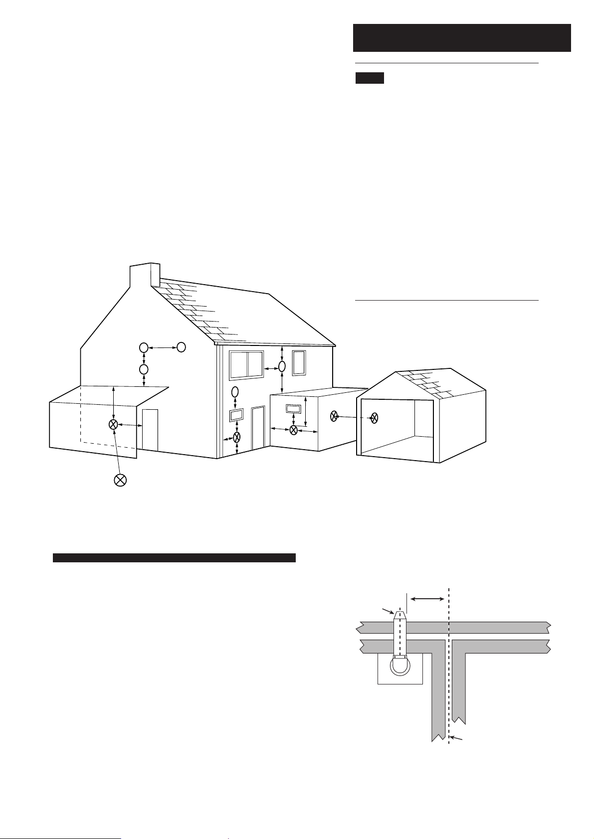
7.8 Flue
1. The flue terminal position must be in
accordance with the current editions of B.S.
5440 Part 1, and either Part J of the Building
Regulations England and Wales or Part F of
the Building Standards (Scotland)
Regulations as appropriate.
2. If the terminal discharges onto a pathway or
passageway, check that combustion products will
not cause a nuisance and that the terminal will
not obstruct the passageway.
3. If a terminal is less than 2 metres above a
balcony, above ground or above a flat roof to
which people have access, then a suitable
terminal guard must be provided.
Terminal Position with Minimum Distance (Fig. 9) (mm)
A Directly below an openable window, air vent or any other
ventilation opening. 300
B Below gutter, drain/soil pipe. 25
C Below eaves. 25
D Below a balcony/car port roof. 25
E From vertical drain pipes and soil pipes. 25
F From internal or external corners. 25
G Above adjacent ground or balcony level. 300
H From a surface facing a terminal. 600
I Facing a terminals. 1200
J From opening (door/window) in carport into dwelling. 1200
K Vertically from a terminal on the same wall. 1500
L Horizontally from a terminal on the same wall. 300
M Above an opening, air brick, opening window etc. 300
N Horizontally to an opening, air brick, opening window etc. 300
L
G
G
E
J
D
K
G
A
A
D
F
H,I
B,C
F
Likely flue positions requiring
a flue terminal guard
M
N
Fig. 9
300 min
Terminal
Assembly
Top View Rear Flue
Property Boundary Line
Page 15
1.0 Introduction
15
7.9 Flue Dimensions
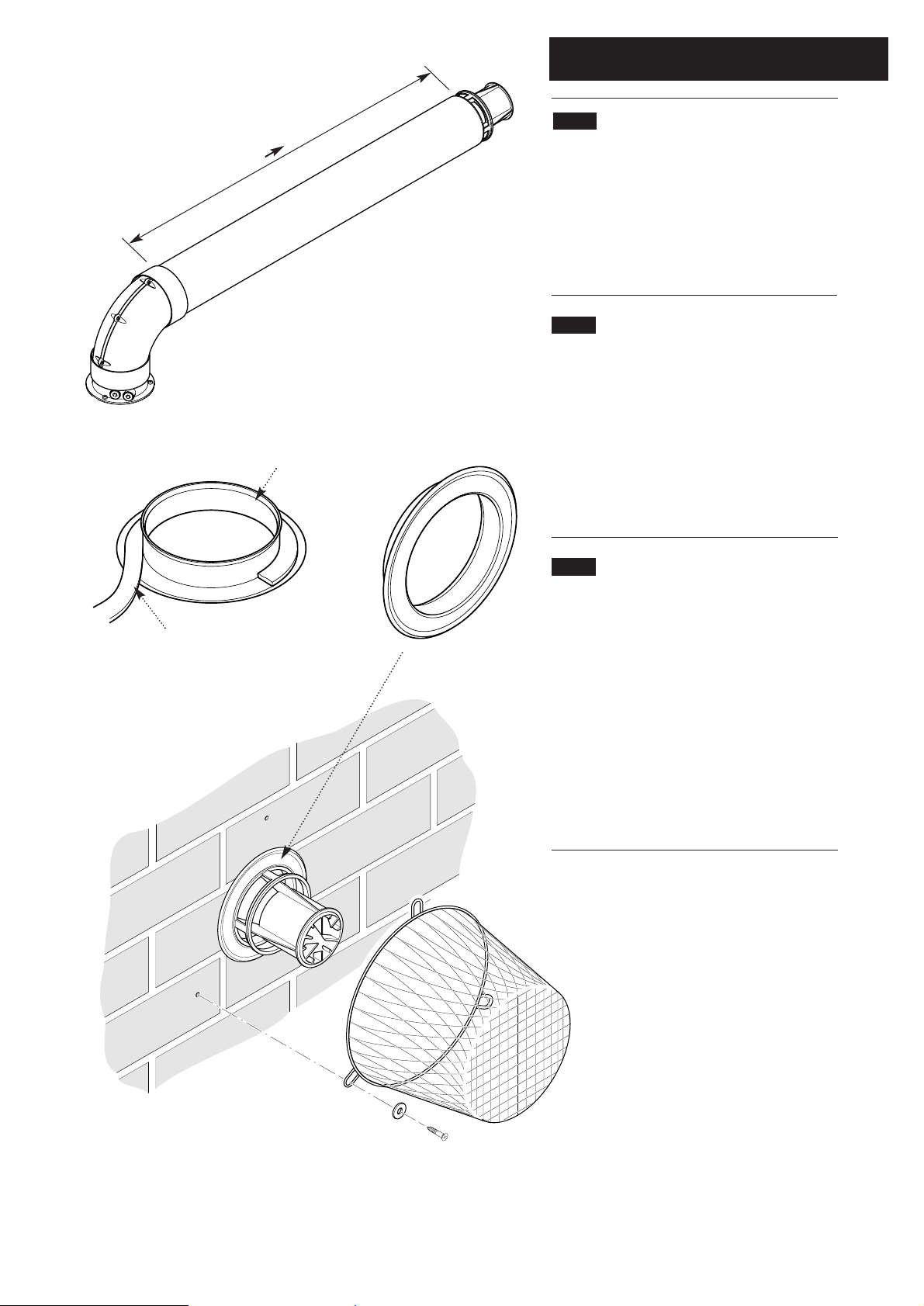
The standard horizontal flue kit allows for flue
lengths between 100mm and 1m from elbow to
terminal (Fig. 10).
The maximum permissible equivalent flue
length is: System 35/60 5 metres
System 60/100 4 metres
7.10 Flue Terminal Trim
1. Once the flue is secure the trim can be fitted if
required.
2. Remove the protective backing from the
adhesive seal. Apply the seal to the rear of the
trim flange (Fig. 11).
3. Locate the trim over the flue terminal and push
it back to the wall to compress the seal (Fig. 12).
7.11 Terminal Guard (Fig. 13)
1. When codes of practice dictate the use of
terminal guards, they can be obtained from most
Plumbers’ and Builders’ Merchants.
2. There must be a clearance of at least 50mm
between any part of the terminal and the guard.
3. When ordering a terminal guard, quote the
appliance name and model number.
4. The flue terminal guard should be positioned
centrally over the terminal and fixed as
illustrated.
Fig. 10
Fig. 13
100mm
1m
Fig. 12
Fig. 11
Flue Trim
Adhesive Seal
Page 16
16
7.0 Site Requirements
7.12 Flue Options
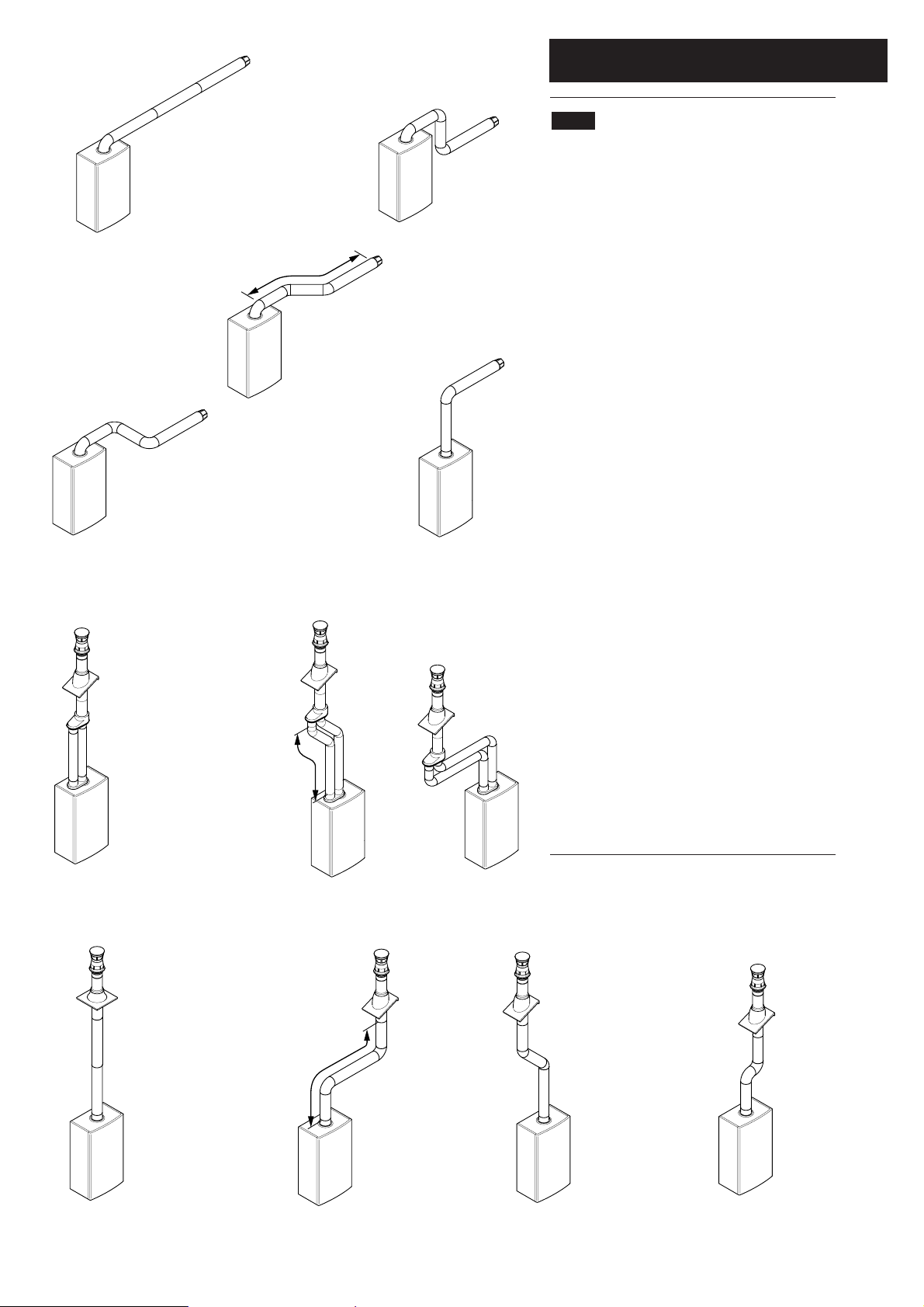
1. The Baxi System 35/60 and 60/100 can be
fitted with flue systems as illustrated.
2. The standard flue is suitable only for horizontal
applications.
3. Maximum permissible equivalent flue lengths
are:-
35/60 60/100
Concentric 5m 4m
Vertical 4m 4m
Vertical Two-Pipe 15m 12m
4. Any additional “in line” bends in the flue system
must be taken into consideration.
Their equivalent lengths are:Concentric Pipes:
45° bend 0.5 metres
90° bend 1.0 metres
Twin Flue Pipe
45° bend 0.25 metres
90° bend 0.50 metres
The elbow supplied with the standard horizontal
flue is not included in any equivalent length
calculations
5. The illustrations opposite show examples of
maximum equivalent lengths.
6. Full details of part numbers and descriptions of
all optional flue components and kits can be
found in the Baxi Gas Central Heating Boilers
Installers’ Guide.
7. Instructions for guidance and fitting are
included in each kit where appropriate.
Horizontal
Flues
Vertical
Flues
Vertical
Flues
(Twin Pipe)
Maximum Length = 3m (60/100) 4m (35/60)
inc. 2 x 45° bends
Maximum Length =
11m (60/100)
14m (35/60)
inc. 4 x 45° bends
Maximum Length = 2m
inc. 2 x 90° bends
Page 17
8.0 Installation
17
8.1 Initial Preparation
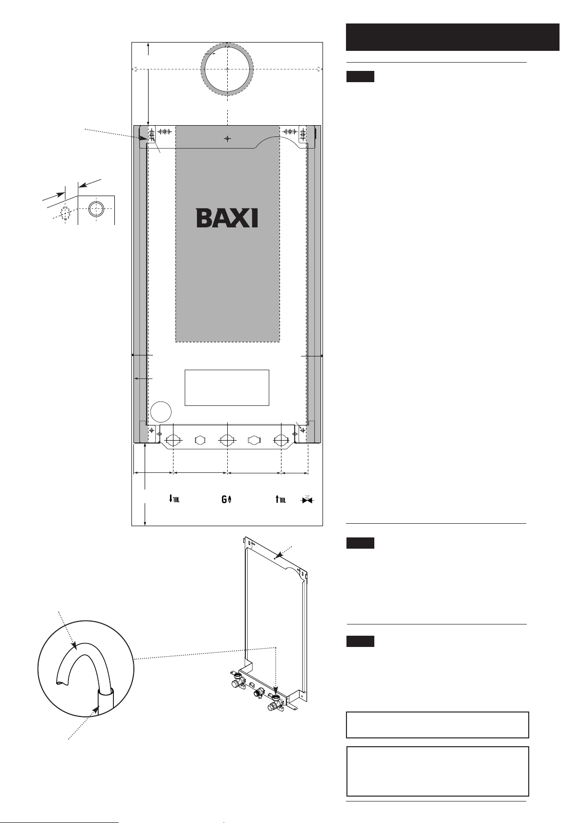
The gas supply, gas type and pressure must be
checked for suitability before connection (see
Section 7.6).
1. After considering the site requirements
(see Section 7.0) position the fixing template
(Fig. 14) on the wall ensuring it is level both
horizontally and vertically.
2. Mark the position of the two most suitable
fixing slots for the wall plate and boiler lower
fixing holes. It is preferable to use the horizontal
fixing slots.
3. Mark the position of the centre of the flue hole
(rear exit). For side flue exit, mark as shown.
4. Note the shaded area on the template.
Pipework may be routed upwards behind the
boiler, providing it does not conflict with the
shaded area.
5. If required, mark the position of the gas and
water pipes. Remove the template.
6. Cut the hole for the flue (minimum diameter
107mm).
7. Drill the wall as previously marked to accept
the wall plugs supplied. Secure the wall plate
using the fixing screws.
8. Using a spirit level ensure that the plate is
level before finally tightening the screws.
9. Connect the gas and water pipes to the valves
on the wall plate using the copper tails supplied.
Ensure that the sealing washers are fitted
between the connections.
8.2 Flushing
1. Connect a tube to the central heating flow or
return pipe (Fig. 15).
2. Flush thoroughly (see System Details, Section
6.2).
8.3 Preparing The Boiler
1. Remove all packaging.
2. Stand the boiler on its base by using the rear
lower edge as a pivot.
NOTE: A small amount of water may drain
from the boiler in the upright position.
Baxi UK Limited declare that no substances
harmful to health are contained in the
appliance or used during appliance
manufacture.
Fig. 14
Fig. 15
System
Boiler
FIXING
TEMPLATE
5 mm Minimum
Side Clearance
5 mm Minimum
Side Clearance
Horizontal Side Flue
Centre Line
107mm Dia Minimum
Aperture For Flue Tube
200 mm
Minimum
Clearance
200 mm
Minimum
Clearance
Profile of
Outercase
Vertical Flue
Centre Line
General
Area For
Electrical
Supply
Heating
Return
(22mm)
Heating
Flow
(22mm)
Pressure Relief
Valve
(15mm)
Gas
Inlet
(22mm)
95 mm
130 mm
Boiler Mounting Bracket Fixing Slots
Drill 8 mm diameter x 50 mm deep
130 mm
65 mm
Boiler Lower Fixing Holes
Drill 8 mm diameter x 50 mm deep
IMPORTANT
Keep rear routed pipework, clips
and electrical cables clear of all
shaded areas to allow the
correct fitting of the boiler chassis
Fixing Template
Appliance Wall Plate
190mm
For Side Flue Exit
Central Heating Return
Flushing Tube
Wall Plate
Page 18
8.0 Installation
18
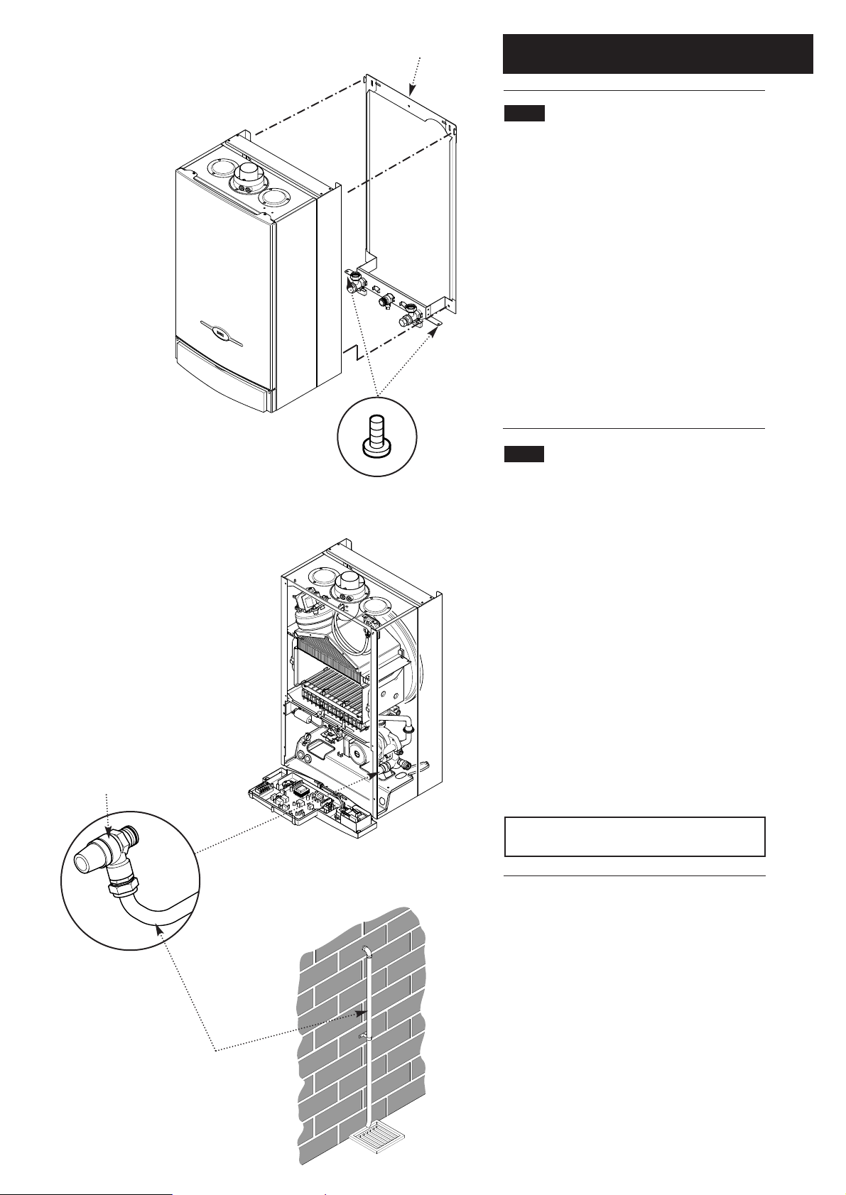
8.4 Fitting The Boiler
1. Remove the sealing caps from the boiler
connections.
2. Lift the boiler using the lower edges. Engage
the slots at the top rear of the boiler on the wall
plate (Fig. 16).
3. Insert the sealing washers between the valves
and pipes on the wall plate and the boiler
connections. The rubber washers must be
used on the gas connection.
4. Tighten all the connections.
5. Secure the boiler side panels to the boiler wall
plate flanges using the screws provided (Fig. 16).
8.5 Fitting the Pressure Relief
Discharge Pipe (Fig. 17)
1. Remove the discharge pipe from the kit.
2. Determine the routing of the discharge pipe in
the vicinity of the boiler. Make up as much of the
pipework as is practical, including the discharge
pipe supplied.
3. The pipework must be at least 15mm diameter
and run continuously downwards to a discharge
point outside the building. See section 6.6 for
further details.
4. Utilising one of the sealing washers, connect
the discharge pipe to the adaptor and tighten the
nut.
5. Complete the discharge pipework and route it
to the outside discharge point.
IMPORTANT: Make all soldered joints before
connecting to the pressure relief valve.
Fig. 17
Fig. 16
Pressure Relief Valve
Wall Plate
Discharge Pipe
Page 19
8.0 Installation
19
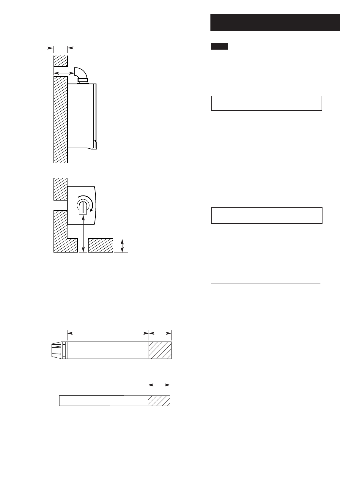
8.6 Fitting The Flue
HORIZONTAL FLUE
1. The standard flue is suitable for lengths
100mm minimum to 1m maximum (measured
from the edge of the flue elbow outlet).
Rear Flue: maximum wall thickness - 900mm
Side Flue: maximum wall thickness - 870mm
2. Locate the flue elbow on the adaptor at the top
of the boiler. Set the elbow to the required
orientation (rear, right or left).
3. Measure the distance from the outside wall
face to the elbow (Fig. 18). This dimension will be
known as ‘X’.
4. Taking the air duct, mark dimension ‘X’ as
shown (Fig. 19). Measure the length of waste
material, and transfer the dimension to the flue
duct (Fig. 19).
IMPORTANT: Check all measurements before
cutting.
5. Remove the waste from both ducts. Ensure
that the cut ends are square and free from burrs.
6. Remove the flue elbow from the adaptor.
7. Insert the flue duct into the air duct and pass
them through the hole in the wall.
Wall Thickness
(X)
Wall Thickness
(X)
Fig. 18
Waste
(X)
Waste
Fig. 19
Air Duct
Flue Duct
Page 20
8.0 Installation
20
8.6 Fitting the Flue (Cont)
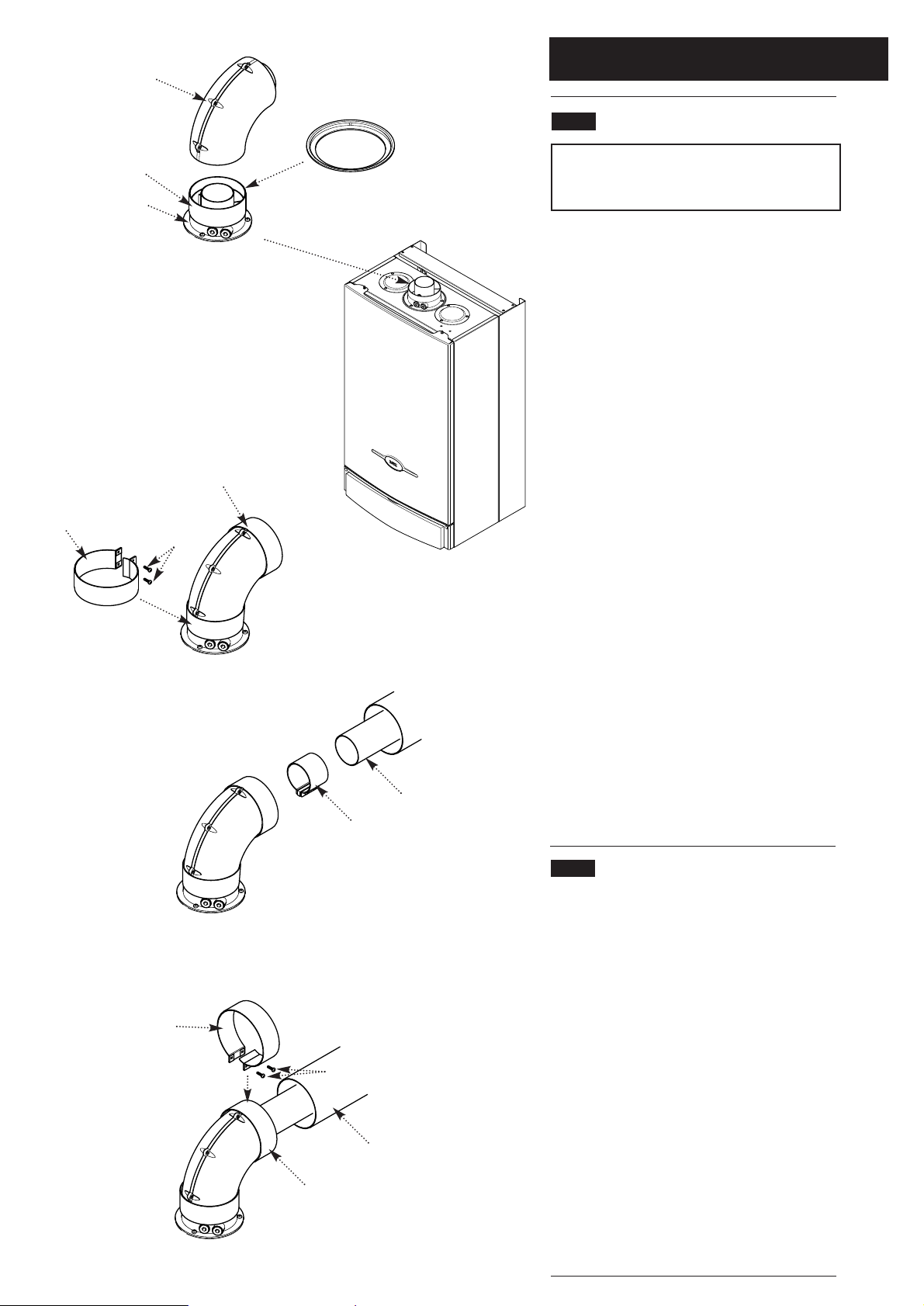
IMPORTANT: If the equivalent flue length is
greater than 1.5m the restrictor MUST be
removed from the adaptor (Fig. 20).
8. Take one of the rubber seals and position it on
the boiler flue adaptor. Engage the flue elbow on
the adaptor and pull the sleeve up so that it
equally covers the joint (Fig. 20).
9. Remove the screws from one of the clips
provided. Prise the clip apart and fit it over the
seal (Fig. 21). Set the elbow to the required angle.
10. Refit the screws to the clip and tighten them to
secure the elbow. Take the second rubber seal
and position it on the flue elbow.
11. Locate the flue duct clamp on the flue outlet
elbow. Draw the flue duct out of the air duct,
engage it in the clamp and tighten the screws
(Fig. 22).
12. Draw the air duct out of the wall and align it
with the elbow. Position the seal so that it equally
covers the joint (Fig. 23).
13. Remove the screws from the second clip
provided. Prise the clip apart and fit it over the
seal. Refit the screws to the clip and tighten them
(Fig. 23).
14. Where possible position the clips so that the
screws are not visible.
15. Make good between the wall and air duct
outside the building.
16. Fit the circular flue trim outside if required, and
if necessary fit a terminal guard (see Section 7.10
& 7.11).
8.7 Extensions & Additional Elbows
1. The method of connecting any flue extensions
or additional elbows is the same as that for
connecting the standard flue and 90° elbow as
described above.
2. If, for example, when a flue extension is
connected to a 90° elbow the flue duct will project
from the air duct at the unconnected end by the
same ammount as the flue duct spigot does from
the elbow . Further elbows or extensions can then
be added to this.
3. Similarly, a concentric flue can be connected to
the boiler adaptor in the same manner as it does
to the elbow to provide a vertical flue.
4. The additional 90° elbow available is identical
to the elbow supplied with the standard flue. 45°
elbows are of the same principle.
5. Extensions can be cut according to the
requirements of the installation.
Fig. 20
Fig. 21
Fig. 22
Seal
Adaptor
Seal
Clip
Screws
Flue Duct
Clamp
Flue Duct
Air Duct
Seal
Clip
Screws
Fig. 23
Restrictor
Elbow
Page 21
8.0 Installation
21
8.8 Making The Electrical Connections
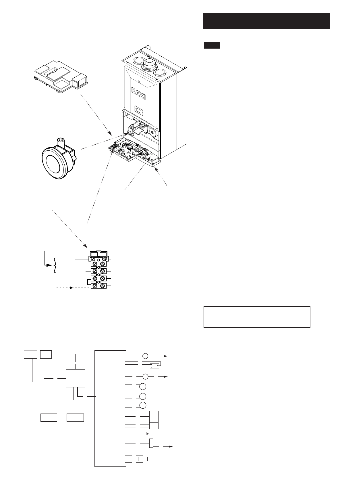
To connect the mains input cable proceed as
follows:-
1. Slacken the facia securing screws and lift the
outercase panel so that its securing tabs are
clear of the facia. Remove the panel.
2. Remove the screws securing the facia panel
and hinge it down (Fig. 24).
3. Remove the control box cover securing
screws. Disengage the barbs on the control box
from the cover. Remove the cover (Fig. 25).
4. Slacken the cable clamp on the LH side of the
boiler chassis (Fig. 26). Insert the cable through
the clamp and route it to the terminal block.
5. Slacken the screws in the terminal block,
connect the input cable, and tighten the screws.
6. If an external control is to be connected it can
be done at this point. Run the input cable from
the external control through the second cable
clamp on the boiler chassis. Refer to the
instructions supplied with the control.
7. To connect external control(s) remove the link
between terminals 1 & 2. The switched output
from the external control must be connected to
terminal 2 (Fig. 27).
8. Any domestic hot water control should be
connected to the DHW relay PCB (Fig. 24) in
most installations. See Section 8.8 for details of
suggested system wiring schemes
IMPORTANT: The external control MUST be
suitable for 230V switching and fused 3A
maximium
9. Ensure that both mains input and, where fitted,
external control input cables have sufficient slack
to allow the control box to drop down. Tighten the
cable clamp(s) on the boiler chassis.
Always fit fast
blow 2A fuse
230V ~ 50Hz
fused 3A maximum
Live (brown)
Neutral (blue)
Earth (green/yellow)
1
2
230V S/L from
external control
br
b
g/y
bk
bk
L
230 V
Selector /
Reset Switch
External
Controls
N
br b
Pump
Hydraulic Differential Pressure Switch
r
r
Safety Overheat Thermostat
b
b
Central Heating
NTC Sensor
r
r
Gas Valve
Spark Electrode
Spark
Generator
Flame Sensing Electrode
N
br b
Fan
N
b
b
br
bk
bk
br
r
Pressure Switch
b
br
bk
PCB
b
b
br
r
bk
bk
br
Primary Return Sensor
g
g
Gas Valve Modulator
DHW
Controls
DHW Relay
PCB
g
g
L
N
Fig. 26
Fig. 25
Fig. 27
Fig. 28
Fig. 24
Terminal Block
Internal Fuse
Cable Clamp
Control Box Cover
Facia Panel
Functional Flow Diagram
Key to Wiring
b - blue
br - brown
bk - black
r - red
g - green
D.H.W. Connections
(DHW Relay PCB)
Page 22
8.0 Installation
22
8.9 System Wiring
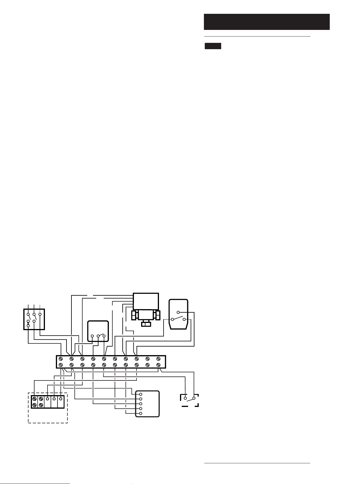
1. The system should include a domestic hot water
cylinder thermostat, room thermostat, timer and
zone valve(s).
2. A system frost protection thermostat is shown in
each diagram. This is in addition to the boiler frost
protection thermostat that is integral to the
appliance.
3. When the boiler selector switch is in the central
heating and domestic hot water position there will
be a 230V supply at terminal 1 of the boiler
terminal strip.
4. The boiler incorporates a domestic hot water
thermostat that allows a maximum temperature of
65°C. For this feature to operate the boiler requires
a switched live feed to the domestic hot water relay
PCB.
5. Methods of wiring several typical heating
schemes are shown. In Scheme 1 the boiler does
not differentiate between central heating and
domestic hot water demands. With Schemes 2, 3 &
4 the boiler utilises the benefit of the integral
domestic hot water thermostat referred to above
which overrides any temperature requirements of
the central heating control(s).
6. It is recommended that the central heating
temperature control is always set at maximum.
Scheme 1
7. Scheme 1 shows the use of a 3 port mid
position zone valve and is based on a ‘Y’ plan
system. The boiler will provide hot water to the
central heating system, domestic hot water store or
both.
8. A live feed to terminal 2 of the boiler terminal
strip controls the boiler. This feed is taken from
either the DHW cylinder thermostat or via the mid
position valve depending upon demand.
9. The timer must supply a signal to the zone valve
when there is no hot water demand in order that
port ‘B’ may be closed off.
10. It is not necessary to connect any control(s) to
the boiler domestic hot water relay PCB. As a
result of this the domestic hot water thermostat will
not operate and the cylinder thermostat must be
relied upon to limit the temperature of DHW.
11. The selector switch must be in the central
heating and domestic hot water position at all times
for the boiler to operate.
E12NL
Terminal Block
312
Room
Thermostat
12345678910
C2
1
Cylinder
Thermostat
Frost
Thermostat
3 Port Valve
Mid Position
Timer
L
NE
230V 50Hz
L
N
HTG
HW On
HW Off
1
3
b
g/y
w
gr
o
A
B
AB
fused 3A maximum
Scheme 1
b - blue
w - white
o - orange
gr - grey
g/y - green/yellow
Baxi System
Boiler
Page 23
8.0 Installation
23
8.9 System Wiring (cont)
Scheme 2
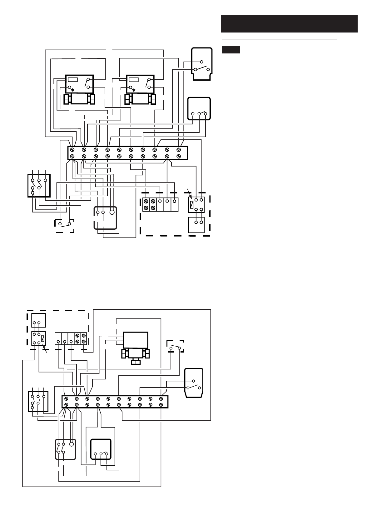
12. Scheme 2 incorporates two 2 port zone valves
and is based on an ‘S’ plan system. The boiler will
provide hot water to the central heating system,
domestic hot water store or both.
13. The boiler is controlled by a live feed from
either zone valve depending upon demand.
14. The domestic hot water relay PCB is fed from
the domestic hot water zone valve. Central
heating demand is controlled by a live feed to
terminal 2 on the boiler terminal strip from the
central heating zone valve.
15. When there is a demand for domestic hot
water the boiler will not supply water at a
temperature greater than 65°C irrespective of the
setting of any central heating control(s) or if the
cylinder thermostat is set higher.
16. Additional 2 port zone valves may be
incorporated in the system as required and wired
in the same manner as the basic system.
Scheme 3
17. Scheme 3 shows the use of a 3 port two
position zone valve and is based on a ‘W’ plan
system. The boiler will provide hot water to the
central heating system or domestic hot water
store.
18. When there is a demand for domestic hot
water and the cylinder thermostat is not satisfied
the zone valve will be energised to open port ‘A’.
19. The zone valve is installed so that port ‘A’ is
connected to the domestic hot water circuit and
port ‘B’ to central heating. This is the reverse of a
conventional ‘W’ plan. It ensures that the valve is
energised only when there is a hot water demand,
not for long periods i.e. central heating demand.
20. The boiler is controlled by a live feed from
either room or cylinder thermostat depending
upon demand.
21. The domestic hot water relay PCB is fed from
the cylinder thermostat. Central heating demand is
controlled by a live feed to terminal 2 on the boiler
terminal strip from the room thermostat.
22. Whilst there is a domestic hot water demand
the central heating circuit will not be served. Once
the cylinder thermostat is satisfied the zone valve
allows circulation of water through the heating
circuit even if the timer still calls for domestic hot
water.
23. When there is a demand for domestic hot
water the boiler will not supply water at a
temperature greater than 65°C even if the cylinder
thermostat is set higher.
M
E12N
N
L
Relay
Board
PCB
Terminal Block
312
Room
Thermostat
12345678 910
C2
1
Cylinder
Thermostat
Zone Valve
DHW
Timer
L
NE
230V 50Hz
L
Zone Valve
HTG
LN
HW
HTG
Motor
Motor
Frost
Thermostat
b
b
o
o
g/y
g/y
br
gr
gr
fused 3A maximum
Scheme 2
b - blue
w - white
o - orange
br - brown
gr - grey
g/y - green/yellow
Scheme 3
Baxi System
Boiler
Baxi System
Boiler
PCB
LN
Relay
Board
230V 50Hz
fused 3A maximum
L
NE
Timer
Room
Thermostat
b
g/y
312
br
DHW
3 Port Valve
2 Position
A
AB
B
Terminal Block
E
12NL
12345678910
M
HTG
DHW
Frost
Thermostat
HTG
Cylinder
Thermostat
1
C2
Page 24
8.0 Installation
24
E12NL
Terminal Block
312
Room
Thermostat
12345678910
C2
1
Cylinder
Thermostat
Frost
Thermostat
3 Port Valve
2 Position
Timer
L
NE
230V 50Hz
L
N
HTG
HW On
HW Off
1
3
b
g/y
w
gr
o
A
B
AB
L
N
PCB
Relay
Board
fused 3A maximum
8.9 System Wiring (cont)
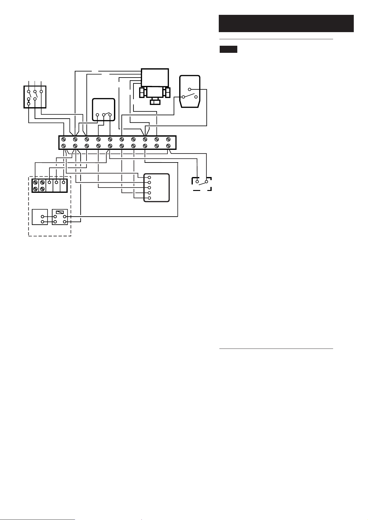
Scheme 4
24. Scheme 4 utilises an existing 3 port mid
position zone valve and is based on a ‘Y’ plan
system but with significant changes. The zone
valve operates as a two position type and the
boiler is controlled as in Scheme 3.
25. To convert a standard ‘Y’ plan to Scheme 4
proceed as follows:-
i) Change the orientation of the zone valve so
that port ‘A’ serves domestic hot water and port
‘B’ the central heating.
ii) Remove the wire between 7 on the terminal
strip and terminal 2 of the cylinder thermostat.
iii) Disconnect the orange zone valve wire from 8
on the terminal strip and connect to 9.
iv) Disconnect the grey zone valve wire from 7
on the terminal strip and connect to 8.
v) Disconnect the white zone valve wire from 5
on the terminal strip and connect to 8.
vi) Connect 8 on the terminal strip to switched
live on the domestic hot water relay PCB.
vii) Connect 5 on the terminal strip to terminal 2
of the boiler terminal block.
26. For isolation purposes both the orange zone
valve wire and the live signal from the timer to
close the domestic hot water port of the zone
valve are connected to “dead” points on the
terminal strip.
b - blue
w - white
o - orange
gr - grey
g/y - green/yellow
Scheme 4
Baxi System
Boiler
Page 25
25
8.0 Installation
8.10 Domestic Hot Water Wiring
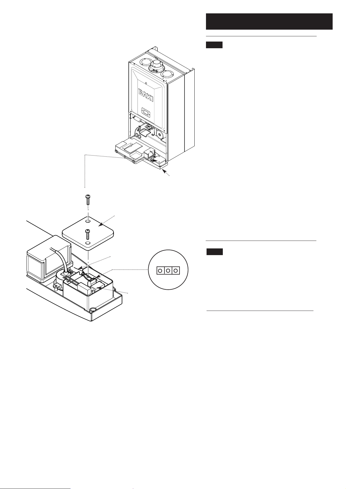
The boiler can be wired to operate when there is
a demand for replenishment of an indirect
domestic hot water storage cylinder.
1. If not already done, slacken the facia securing
screws sufficiently to release the outercase panel
securing tabs. Lift and remove the panel.
2. Remove the screws securing the facia panel
and hinge it down.
3. Slacken the cable clamp on the R.H. side of
the boiler chassis. Insert the cable from the
cylinder thermostat through the cable clamp.
4. Undo the screws securing the DHW relay PCB
cover. Remove the cover. Slacken the screws in
the terminal block on the PCB and connect the
switched live and neutral (Fig. 29).
5. Lay the input cable in the cut out in the relay
PCB housing and refit the cover and screws.
6. Ensure that the input cable has sufficient slack
to allow the control box to drop down. Tighten the
cable clamp on the boiler chassis.
8.11 Preliminary Electrical Checks
1. Prior to commissioning the boiler preliminary
electrical system checks should be carried out.
2. These should be performed using a suitable
meter, and include checks for Ground Continuity,
Resistance to Ground, Short Circuit and Polarity.
N
L
Fig. 29
DHW Relay
PCB Cover
DHW Control
Input Cable
DHW Relay PCB
Facia Panel
Page 26
9.0 Commissioning the Boiler
26
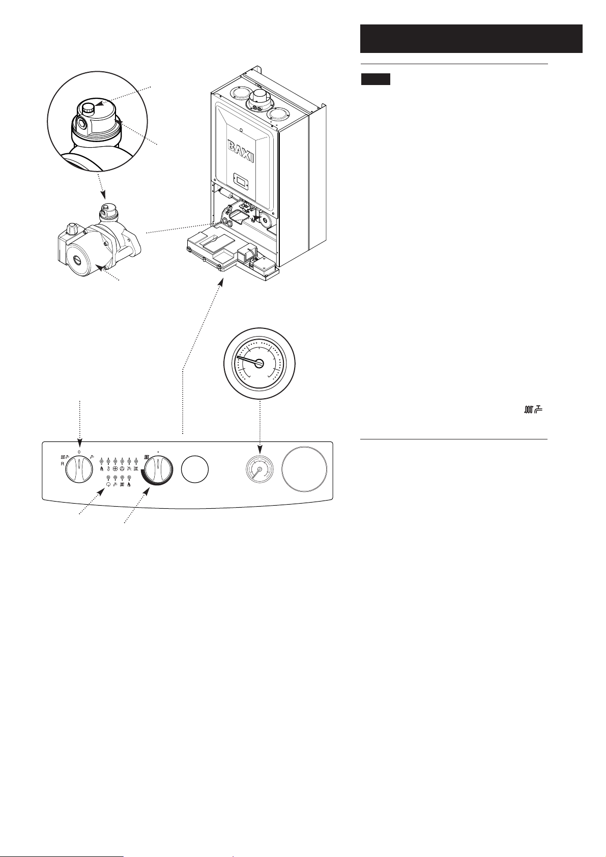
9.1 Commissioning the Boiler
1. Reference should be made to BS 5449 when
commissioning the boiler.
2. Ensure that the filling loop is connected and
open, then open the heating flow and return
valves on the boiler.
3. Open the screw on the automatic air vent
(Fig. 30).
4. The system must be flushed in accordance
with BS 7593 and the flushing agent
manufacturers instructions.
5. Pressurise the system to 0.2 bar then close
and disconnect the filling loop.
6. Turn the gas supply on and purge the system
according to BS 6891.
7. Test for gas soundness.
8. If at any time during commissioning it is
required to terminate a particular cycle, e.g. the
pump overrun period, turn the selector to the Off
position and then back to the On position ( )
(Fig. 32).
Automatic
Air Vent
Pressure
Gauge
Screw
2
1
0
4
3
bar
Fig. 30
Selector Switch
Central Heating
Temperature Control
Fig. 31
30° 40° 50° 60° 70° 80°
2
1
0
4
3
bar
Pump
Fig. 32
Power On
Neon
Page 27
9.0 Commissioning the Boiler
27
OUT
MIN
Pressure Test Point
Sealing Screw
Fig. 33
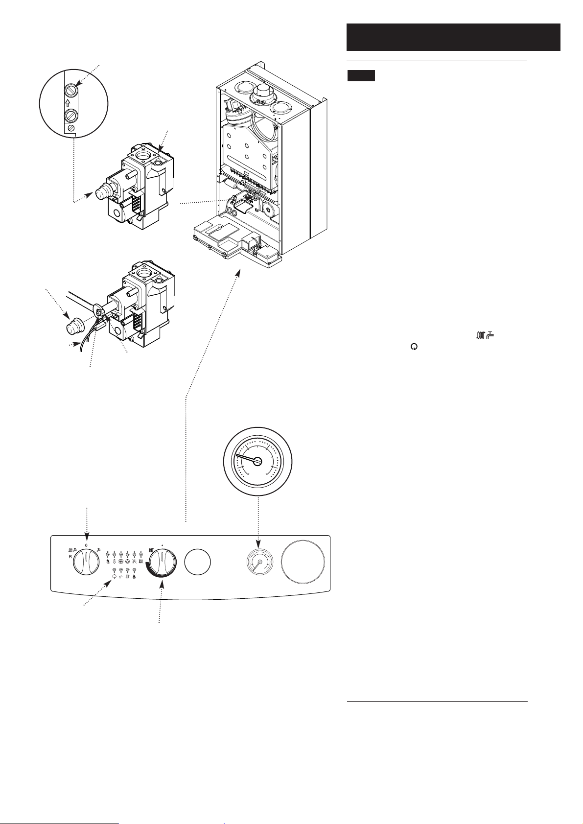
9.2 Checking the Burner Pressure
1. Turn on the gas and electrical supplies to the
boiler and ensure that all external controls are
calling for heat.
2. Set the temperature control to maximum and
the selector switch to the Off position (Fig. 36).
3. Slacken the pressure test point sealing screw
on the gas valve and connect a pressure gauge
(Fig. 33).
4. Undo the screws securing the inner door panel.
Lift the panel slightly to disengage it from the
studs on top of the case.
5. Turn the selector switch fully anticlockwise
against the spring pressure to position R and hold
for 2 seconds to reset the boiler.
6. Turn the selector switch to the Cental Heating
and Domestic Hot Water position ( ). The
power On neon ( ) will illuminate (Fig. 36).
7. The pressure should be as quoted in Section
4.0 Technical Data. If not, check that the gas
supply pressure is correct (Natural Gas 20mbar,
Butane 30mbar and Propane 37mbar).
8. The pressure can be adjusted if required.
9. To check and set minimum pressure first
remove one of the modulator wires.
Adjusting the Pressure (Fig 34)
10. Remove the plastic protection cap from the
pressure adjustment nuts on the valve.
11. The smaller nut (5mm) adjusts minimum
pressure and the larger nut (8mm) maximum
pressure.
12. Using a suitable spanner adjust the relevant
nut until the correct pressure is achieved.
13. Once the pressure has been set turn the
boiler off and disconnect the pressure gauge.
14. Tighten the pressure test screw and refit the
modulator to the valve. Reassemble in reverse
order.
Selector Switch
Temperature Control
30° 40° 50° 60° 70° 80°
2
1
0
4
3
bar
Fig. 36
Power On Neon
Pressure
Gauge
2
1
0
4
3
bar
Fig. 35
Gas Valve
Fig. 34
Plastic
Protection
Cap
Modulator
Wire
Maximum Rate
Adjustment Nut
Minimum Rate
Adjustment Nut
Page 28
10.0 Completion
28
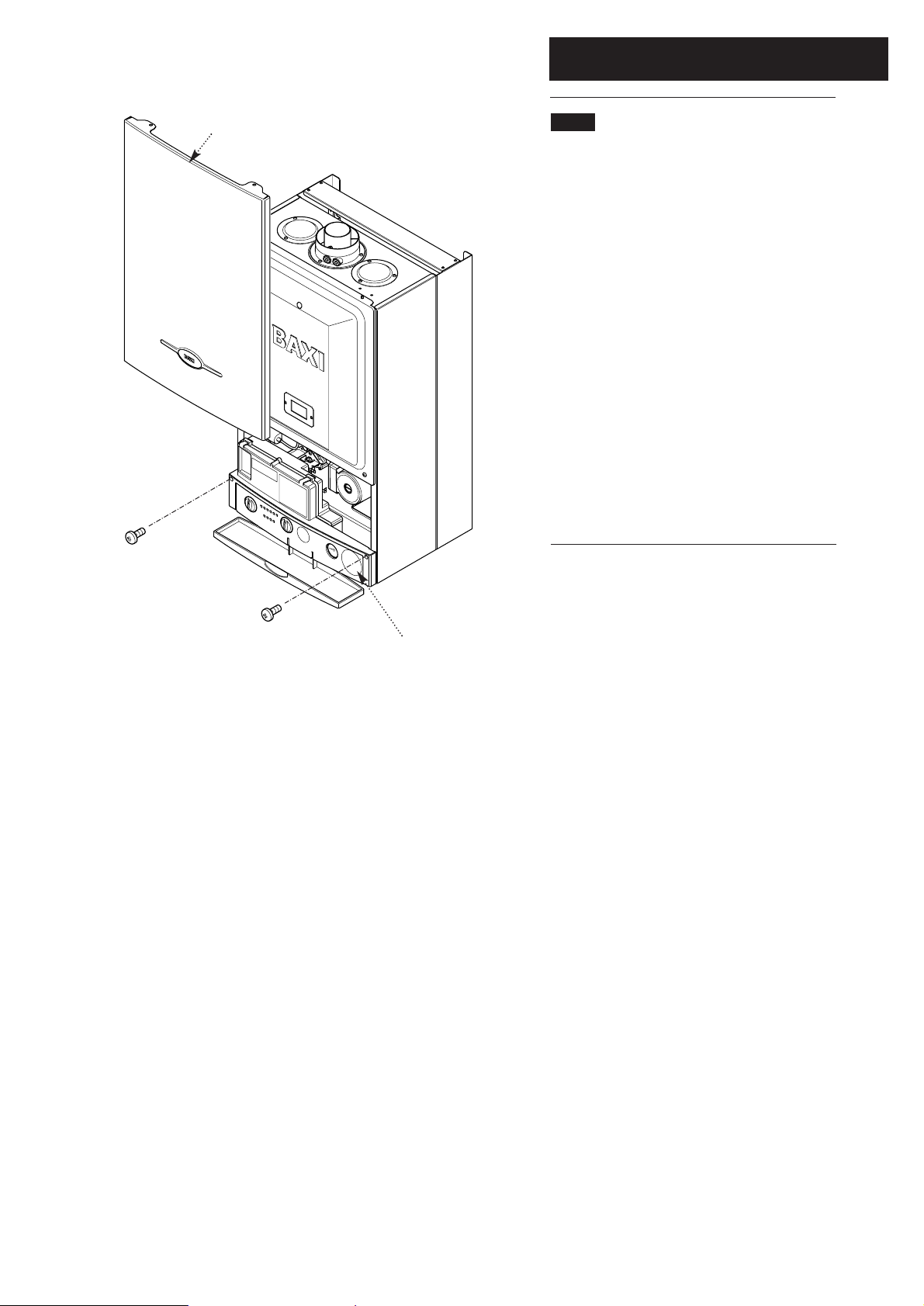
10.1 Completion
1. Hinge the facia panel upwards and refit the
case front panel. Secure them with the screws
previously removed (Fig. 37).
2. Instruct the user in the operation of the boiler
and system, explaining the operational sequence.
3. Carefully read and complete all sections of the
“Benchmark” Installation, Commissioning and
Service Record Log Book that are relevant to the
appliance and installation. The details of the Log
Book will be required in the event of any warranty
work. The Log Book must be handed to the user
for safe keeping and each subsequent regular
service visit recorded.
4. Hand over the Users Operating, Installation
and Servicing Instructions and the Log Book,
giving advice on the necessity of regular
servicing.
Fig. 37
Facia Panel
Case Front Panel
Page 29
11.0 Servicing the Boiler
29
11 .1 Annual Servicing
1. For reasons of safety and economy, it is
recommended that the boiler is serviced annually.
Servicing must be performed by a competent
person.
2. After servicing, complete the relevant section of
the “Benchmark” Installation, Commissioning and
Service Record Log Book. This should be in the
possession of the user.
3. Ensure that the boiler is cool.
4. Ensure that both the gas and electrical
supplies to the boiler are isolated.
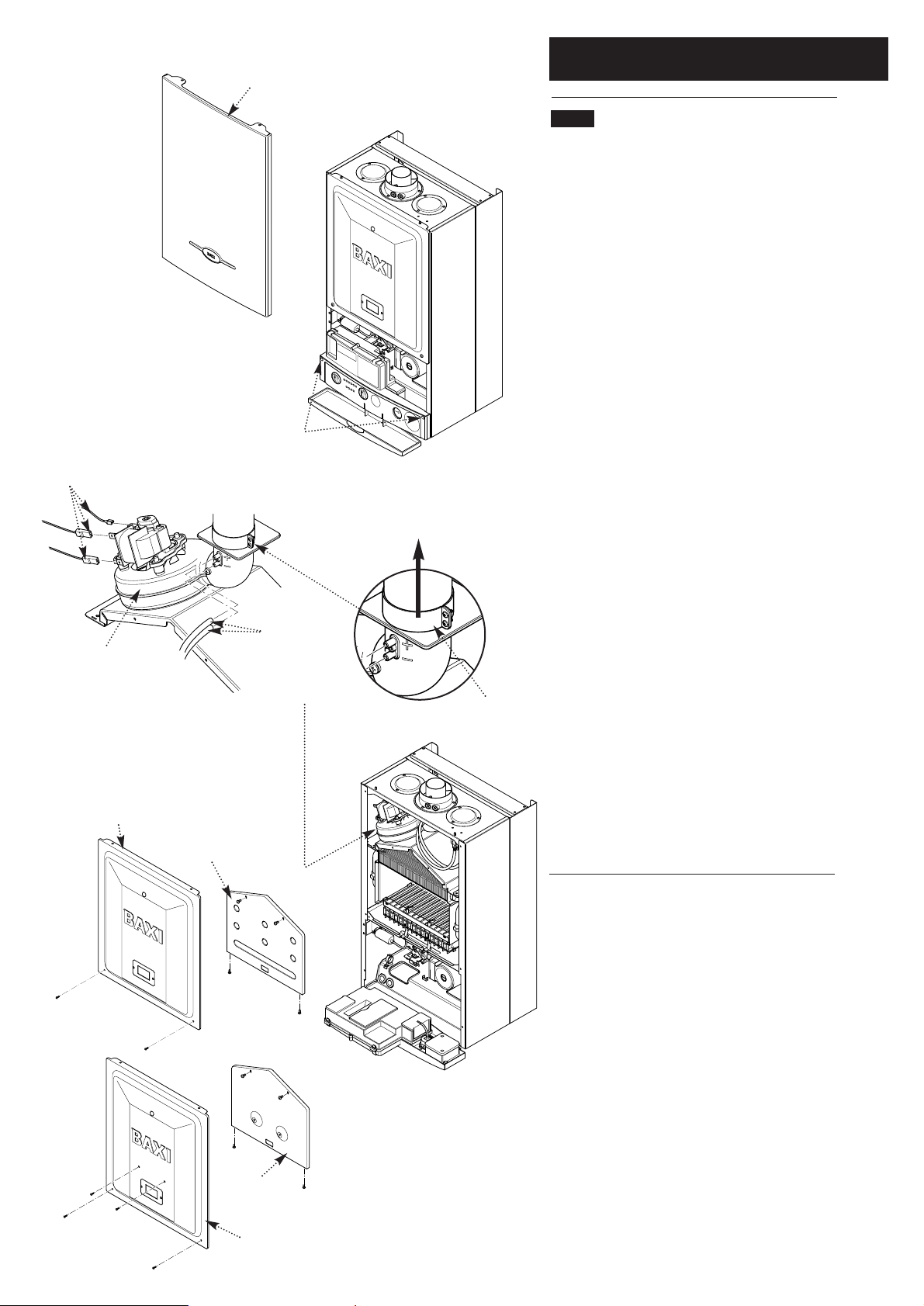
5. Slacken the screws securing the facia panel.
Lift the outercase panel so that its securing tabs
are clear of the facia. Remove the panel (Fig. 38).
6 Remove the facia securing screws and hinge
the panel down.
7. Remove the screws (2 on 35/60, 4 on 60/100)
securing the inner door panel. Lift the panel
slightly to disengage it from the studs on top of
the case (Fig. 39).
8. Note the positions of the two sensing tubes on
the outlet elbow and three wires on the fan motor
and remove them (Fig. 40).
9. Slacken the screws on the outlet sealing collar.
Ease the collar upwards as far as possible
(Fig. 40).
10. Remove the four screws securing the
combustion box door and remove the door
(Fig. 39).
Fan Wires
Fan
Sensing
Tubes
Outlet Sealing
Collar
Combustion
Box Door
Inner Door
Panel
Case Front Panel
Ease Outlet Sealing
Collar Upwards
Fig. 38
Facia Panel
Securing Screws
Fig. 41
Fig. 40
Inner Door
Panel
Combustion
Box Door
35/60 models
60/100 models
Page 30
11.0 Servicing the Boiler
30
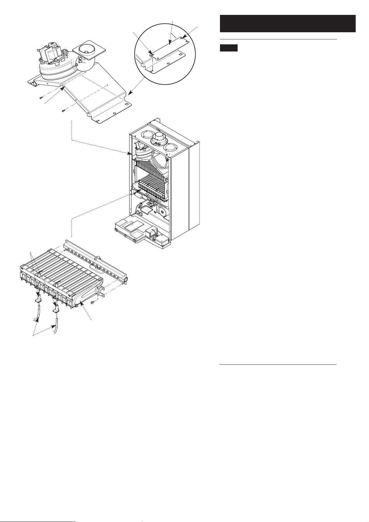
11.1 Annual Servicing (Cont)
11. Remove the spring clips retaining the air box
side baffle plates. Disengage the tabs on the
baffles from the slots in the fan hood (Fig. 41).
12. Undo the screws securing the fan and hood to
the appliance back panel. Draw the assembly
forwards (Fig. 42).
13. Undo the screws securing the burner to the
injector manifold (60/100 model only). Draw the
burner out of the combustion box, pulling the
electrode grommets from the slots in the
combustion box lower panel (Fig. 43).
14. Disconnect the electrode leads and grommets
from the electrodes. Completely remove the
burner (Fig. 43).
15. Brush any deposits from the injectors. Do not
use a pin or wire to clean them.
16. Brush the burner blades and venturis and
clean the combustion box.
17. Ensure that the heat exchanger fins are clear
of any obstruction.
18. Check that the pressure vessel charge is
0.5bar and reassemble in reverse order of
dismantling.
19. Turn the selector switch fully anticlockwise
against the spring pressure to position R and hold
for 2 seconds to reset the boiler before
recommissioning.
20. Complete the relevant section of the
“Benchmark” Installation, Commissioning and
Service Record Log Book and hand it back to the
user.
Spring Clip
Fan and Hood
Assembly
Baffle
Tab
Burner
Electrode
Grommets
Fig. 41
Fig. 43
Fig. 42
Page 31
12.0 Changing Components
31
IMPORTANT: When changing components
ensure that both the gas and electrical
supplies to the boiler are isolated before any
work is started. When the new component has
been fitted turn the selector switch fully
anticlockwise against the spring pressure to
position R and hold for 2 seconds to reset the
boiler before recommissioning.
See Section 11.1 “Annual Servicing” for removal
of case panel, door etc.
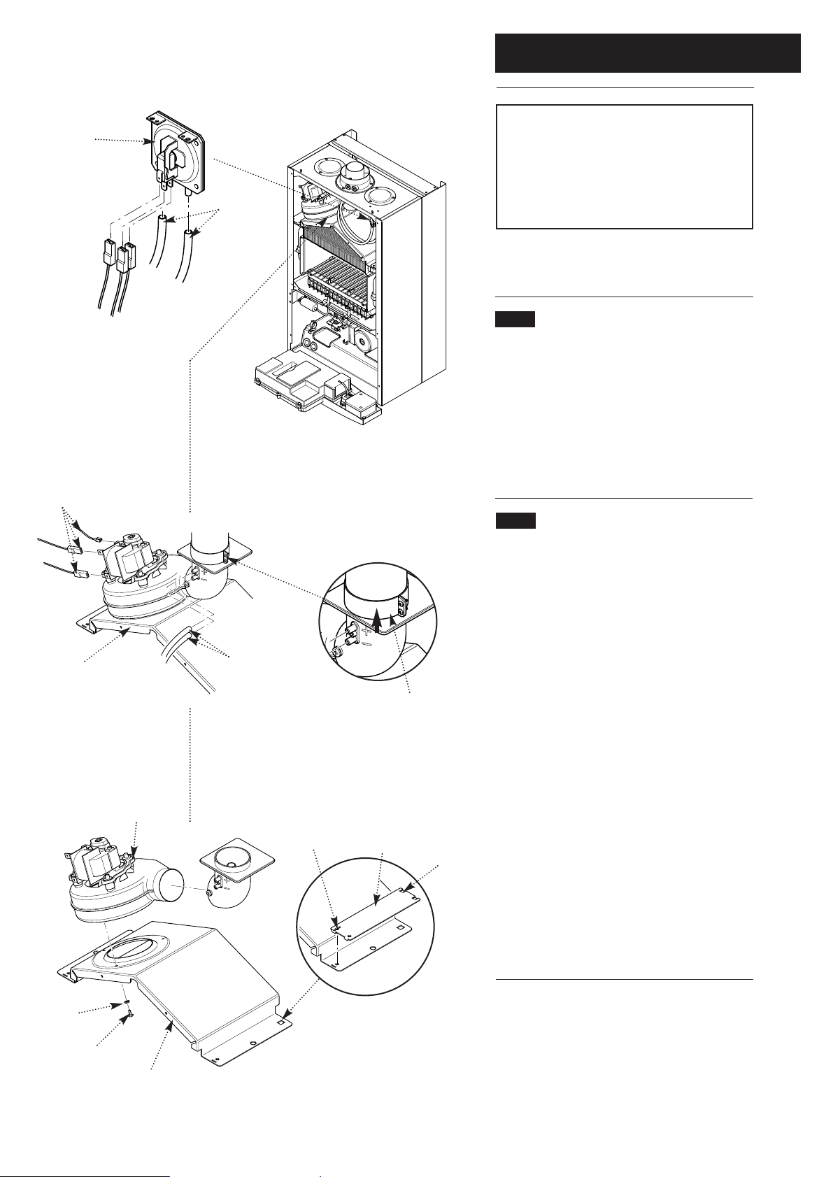
12.1 Pressure Switch (Fig. 44)
1. Note the positions of the two sensing tubes
and three wires and remove them.
2. Remove the two screws holding the pressure
switch to the combustion box top panel.
3. Fit the new pressure switch and reassemble all
components in reverse order of dismantling.
12.2 Fan (Figs. 45 & 46)
1. Note the positions of the two sensing tubes on
the outlet elbow and three wires on the fan motor
and remove them.
2. Slacken the screws on the outlet sealing collar.
Ease the collar upwards as far as possible.
3. Remove the four screws securing the
combustion box door and remove the door.
4. Remove the spring clips retaining the air box
side baffle plates. Disengage the tabs on the
baffles from the slots in the fan hood.
5. Undo the screws securing the fan hood to the
appliance back panel, and draw the fan and hood
assembly forwards.
6. Remove the screws and spring washers
securing the fan to the hood.
7. Fit the new fan to the hood using the screws
and spring washers previously removed.
8. Reassemble in reverse order of dismantling.
Spring Clip
Fan
Fan Hood
Spring
Washer
Securing Screw
Baffle
Tab
Fan Wires
Fan and Hood
Assembly
Sensing Tubes
Outlet Sealing
Collar
Pressure
Switch
Sensing
Tubes
Pressure
Switch Wires
Fig. 44
Fig. 45
Fig. 46
Page 32
12.0 Changing Components
32
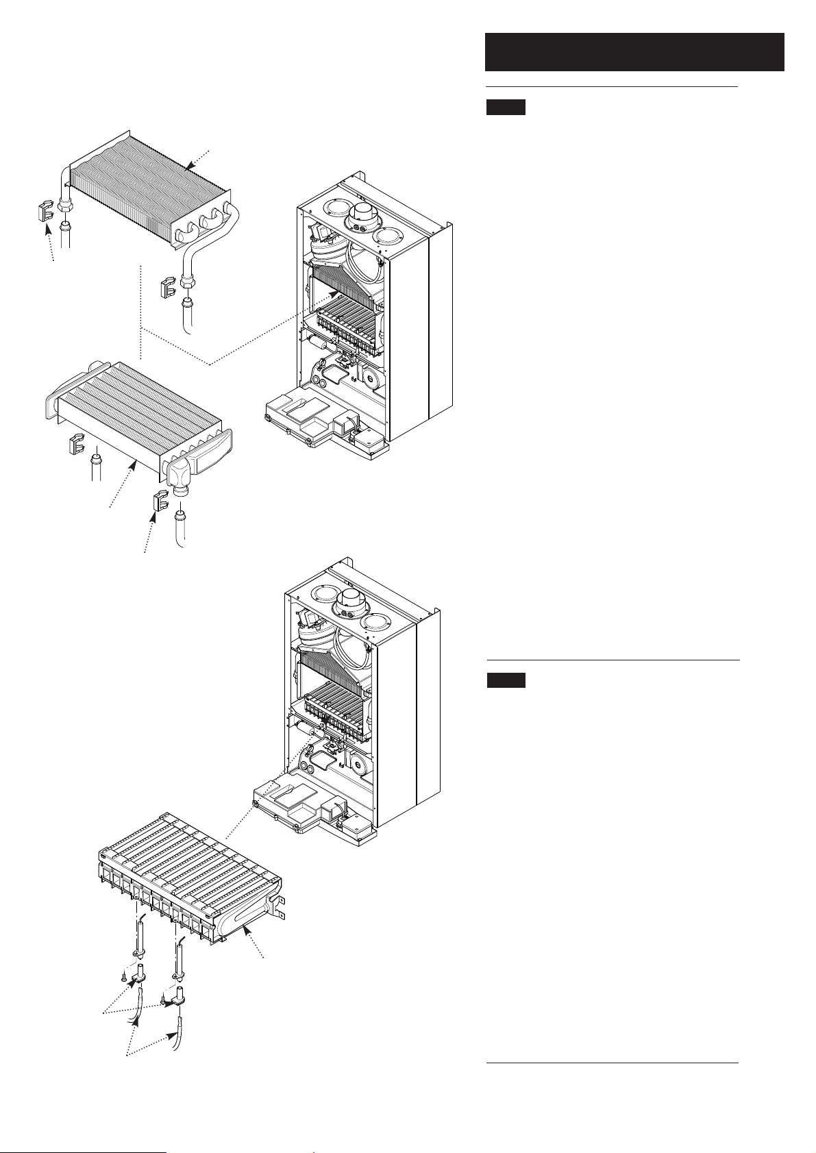
12.3 Heat Exchanger (Fig. 47)
1. Note the positions of the two sensing tubes on
the outlet elbow and three wires on the fan motor
and remove them.
2. Slacken the screws on the outlet sealing collar.
Ease the collar upwards as far as possible.
3. Remove the four screws securing the
combustion box door and remove the door.
4. Remove the spring clips retaining the air box
side baffle plates. Disengage the tabs on the
baffles from the slots in the fan hood.
5. Undo the screws securing the fan hood to the
appliance back panel, and draw the fan and hood
assembly forwards.
6. Drain the primary circuit. Prise the two pipe
connecting clips off the joints in the flow and
return pipes.
7. Lift the heat exchanger to disconnect the flow
and return pipe joints. Withdraw it from the
appliance, taking care not to damage the rear
insulation piece.
8. Fit the new heat exchanger.
9. Reassemble in reverse order of dismantling,
and repressurise the system.
12.4 Burner (Fig. 48)
1. Remove the four screws securing the
combustion box door and remove the door.
2. Undo the screws securing the burner to the
injector manifold (60/100 model only). Draw the
burner out of the combustion box, pulling the
electrode grommets from the slots in the
combustion box lower panel.
3. Disconnect the electrode leads and grommets
from the electrodes. Completely remove the
burner.
4. Undo the screws securing the electrodes to the
burner. Examine the condition of the electrodes,
replacing if necessary. Fit the electrodes to the
new burner.
5. Engage the burner location brackets over the
studs on the injector manifold and reassemble in
reverse order.
Burner
Electrode
Grommets
Electrode
Leads
Electrodes
Heat Exchanger
(35/60 model)
Fig. 47
Heat Exchanger
(60/100 model)
Pipe Connecting
Clips
Pipe Connecting
Clips
Fig. 48
Page 33
12.0 Changing Components
33
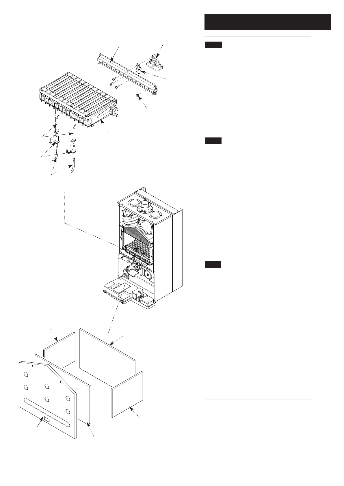
12.5 Injectors (Fig. 49)
1. Remove the burner as described in Section
12.4.
2. Undo the screws securing the injector
manifold to the inlet elbow and remove the
manifold.
3. Unscrew and replace injectors as required
and examine the sealing gasket, replacing as
necessary. Reassemble in reverse order.
12.6 Electrodes (Fig. 49)
1. Remove the four screws securing the
combustion box door and remove the door.
2. Undo the screws securing the burner to the
injector manifold (60/100 model only). Draw the
burner out of the combustion box, pulling the
electrode grommets from the slots in the
combustion box lower panel.
3. Disconnect the lead and grommet from the
electrode being replaced. Undo the securing
screw and withdraw the electrode to the burner.
4. Reassemble in reverse order.
12.7 Insulation (Fig. 50)
1. Remove the four screws securing the
combustion box door and remove the door.
2. Slide the side insulation pieces carefully out
of their carriers.
3. To replace the rear insulation piece it is
necessary to remove the heat exchanger as
described in Section 12.3 and slide out the side
pieces.
4. The combustion box door insulation piece
can be replaced by carefully bending up the two
retaining tabs.
5. Replace all insulation pieces and reassemble
in reverse order.
13.8
Injector
Manifold
Inlet Elbow
Gasket
Injector
Burner
Electrode
Grommets
Electrode
Leads
Side Insulation
Rear Insulation
Front Insulation
Combustion
Box Door
Side Insulation
Electrodes
Fig. 49
Fig. 50
Page 34
12.0 Changing Components
34
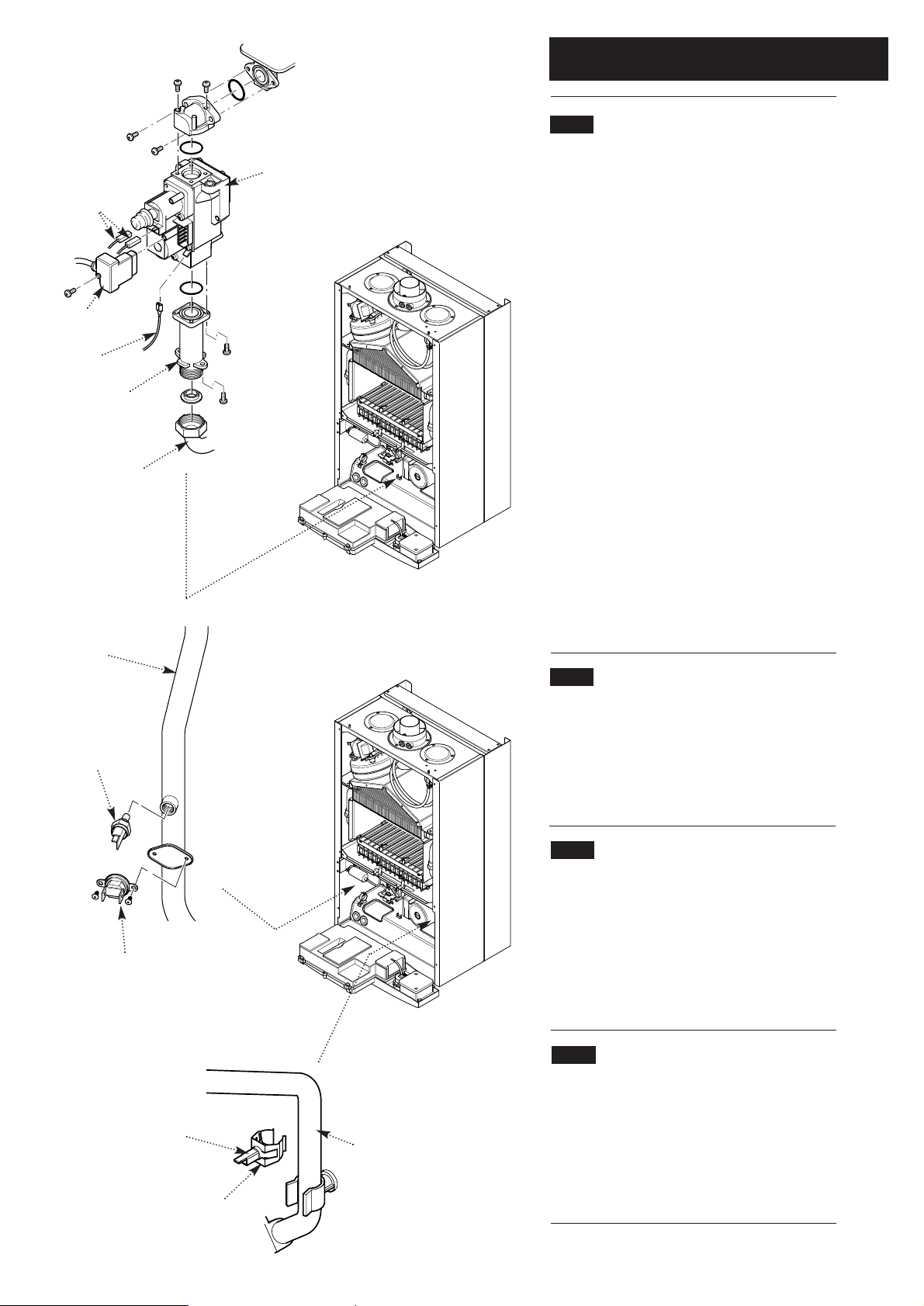
12.8 Gas Valve (Fig. 51)
1. Undo the nut on the gas feed pipe under the
boiler.
2. Remove the securing screws and hinge the
facia panel down.
3. Disconnect the earth wire and pressure sensing
pipe from the valve. Undo the screw securing the
electrical plug to the valve and disconnect the
plug. Disconnect the wires from the valve
modulator.
4. Remove the screws securing the inlet pipe
flange to the boiler bottom panel and those
securing the outlet manifold to the burner
manifold.
5. Remove the valve from the boiler.
6. Note the orientation of the inlet pipe and outlet
manifold. Undo the securing screws and remove
the pipe and manifold.
7. Examine the ‘O’ ring seals for damage,
replacing as necessary.
8. Fit the inlet pipe and outlet manifold to the new
valve, ensuring that the ‘O’ ring seals are in place.
9. Reassemble in reverse order and check the
burner pressure as described in Section 9.2.
12.9 Central Heating Temperature Sensor
(Fig. 52)
1. Ease the retaining tab on the sensor away and
disconnect the electrical plug.
2. Unscrew the sensor from it’s pocket and
reassemble in reverse order. The plug will only fit
one way.
12.10 Safety Thermostat (Fig. 52)
1. Pull the electrical connections off the
thermostat.
2. Remove the screws securing the thermostat to
the mounting plate on the flow pipe.
3. Reassemble in reverse order. The thermostat is
not polarised - either wire can fit either terminal on
the thermostat.
12.11 Return Heating
Temperature Sensor
(Fig. 53)
1. Ease the retaining tab on the sensor away
and disconnect the electrical plug.
2. Prise the sensor retaining clip off the pipe and
remove the sensor from the clip.
3. Reassemble in reverse order.
Gas Valve
Inlet Pipe
Gas Feed
Pipe
Earth Wire
Electrical
Plug
Central Heating
Temperature Sensor
Safety
Thermostat
Return Heating
Temperature Sensor
Retaining Clip
Heating Return Pipe
Flow Pipe
Fig. 51
Fig. 52
Fig. 53
Modulator
Wires
Page 35
12.0 Changing Components
35
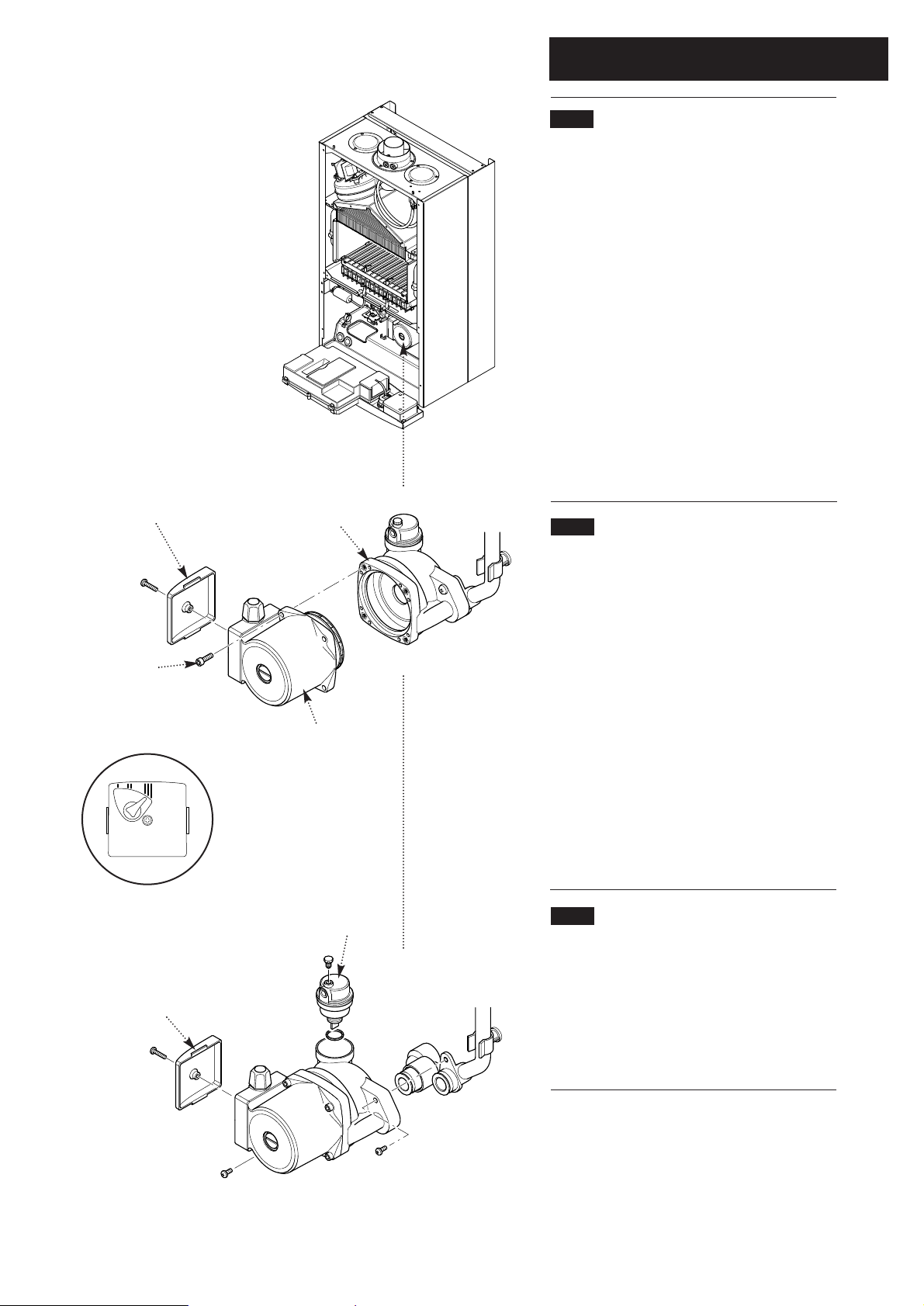
12.12 Pump - Head Only (Fig. 54)
1. Drain the primary circuit and remove the
socket head screws securing the pump head to
the body and draw the head away.
2. Undo the screw on the pump wiring cover and
remove the cover. Using a suitable flat bladed
screw driver press the cable securing levers
downwards to release each wire after noting their
position.
3. A standard Grundfos replacement head can
now be fitted. A Grundfos 15-50 head is suitable
for the System 35/60. The System 60/100
requires a 15-60 head. Connect the wiring to the
new head. The pump speed must be set to 3
(Fig. 55).
4. Reassemble in reverse order.
12.13 Pump - Complete (Fig. 56)
1. Drain the primary circuit and unscrew the
automatic air vent from the pump body. Undo the
two screws securing the body to the pipe and
manifold and draw the pump forwards.
2. Undo the screw on the pump wiring cover and
remove the cover. Using a suitable flat bladed
screw driver press the cable securing levers
downwards to release each wire after noting their
position.
3. Connect the wiring to the new pump. Examine
the ‘O’ ring seals on the return pipe and manifold,
replacing if necessary.
4. Fit the air vent to the pump body and
reassemble in reverse order.
12.14 Automatic Air Vent (Fig. 56)
1. Drain the primary circuit and unscrew the
automatic air vent from the pump body.
2. Examine the ‘O’ ring seal, replacing if
necessary, and fit it to the new automatic air vent.
3. Reassemble in reverse order.
Pump Setting
Pump Wiring
Cover
Socket Headed
Screw
Pump Head
Pump Body
Pump Wiring
Cover
Automatic
Air Vent
Fig. 54
Fig. 56
Fig. 55
Page 36
12.0 Changing Components
36
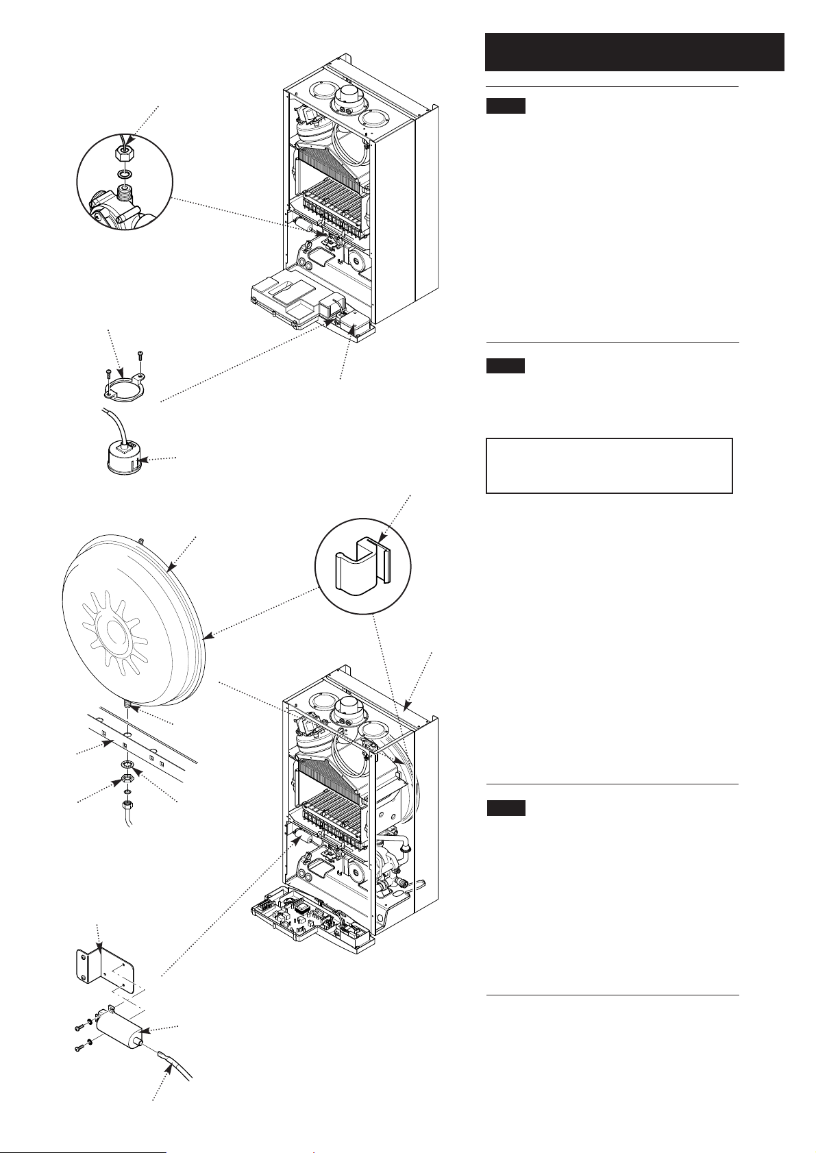
12.15 Pressure Gauge (Figs. 57 & 58)
1. Drain the primary circuit and undo the nut on
the pressure gauge capillary.
2. Remove the timer cover and ease the timer
wiring aside. Undo the screws securing the
gauge retaining bracket.
3. Remove the bracket and gauge assembly.
Depress the barbs on the side of the gauge and
remove the retaining bracket.
4. Reassemble in reverse order.
12.16 Expansion Vessel (Fig. 59)
1. To replace the expansion vessel it is
necessary to remove the boiler from the wall.
NOTE: Alternatively a vessel of equivalent
capacity can be fitted on the system return
pipe as close as possible to the boiler.
2. Drain the system and undo all gas and water
connections. Remove the flue elbow.
3. Lift the boiler off the wall plate and lay it on
either side on a clean flat surface.
4. Undo the nut on the vessel outlet spigot, and
remove the locknut and spring washer securing
the spigot to the boiler chassis.
5. Undo the screws and remove the appliance
upper cross member. Slide the expansion vessel
out of the retaining clips.
6. Reassemble in reverse order. Fully
recommission the appliance and system.
12.17 Spark Generator (Fig. 60)
1. Pull the electrode lead off the spark
generator. Remove the screws and spring
washers securing the generator to its mounting
bracket.
2. Pull the rubber shroud off the generator input
plug and disconnect the plug.
3. Reassemble in reverse order.
Pressure Gauge
Timer Cover
Pressure Gauge
Capillary
Gauge Retaining
Bracket
Expansion Vessel
Retaining Clip
Vessel Outlet
Spigot
Boiler
Chassis
Lock Nut
Spring
Washer
Electrode Lead
Spark Generator
Mounting Bracket
Fig. 57
Fig. 58
Fig. 59
Fig. 60
Upper Cross
Member
Page 37
12.0 Changing Components
37
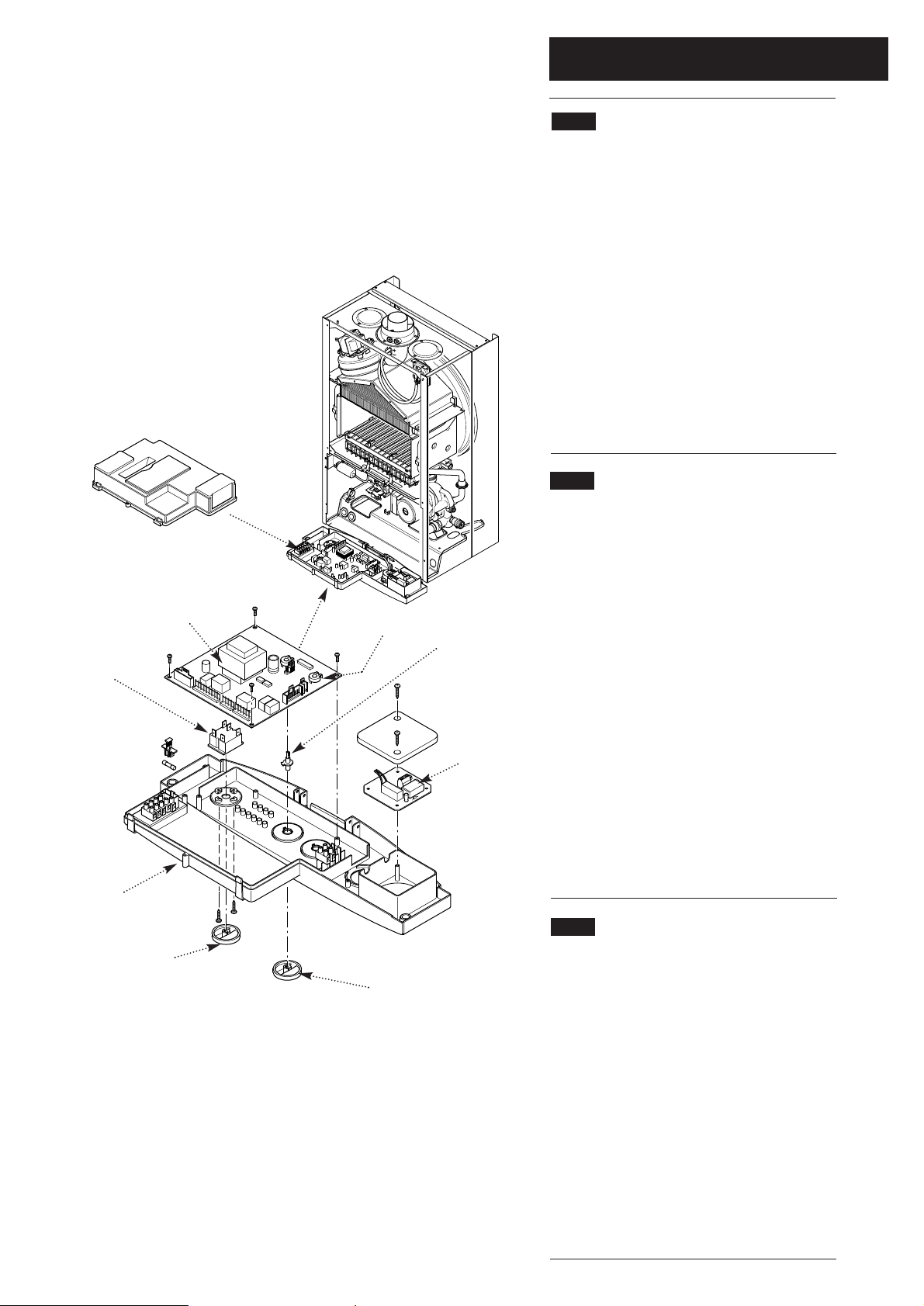
12.18 DHW Relay PCB (Fig. 62)
1. Undo the screws securing the DHW relay PCB
cover. Remove the cover.
2. Remove the screws securing the control box
cover and release the cover retaining barbs from
their slots. Disengage the rear of the cover from
the control box hinge pin.
3. Disconnect the live feed and neutral from the
external control at the relay PCB.
4. Disconnect the green wires from the 2-way
electrical connection block adjacent to the main
PCB. Undo the securing screws and remove the
relay PCB.
6. Reassemble in reverse order.
12.19 Main PCB (Fig. 62)
1. Note the setting of the temperature control
knob. Rotate the knob fully anticlockwise and
carefully pull it off the drive pin.
2. Remove the screws securing the control box
cover and release the cover retaining barbs from
their slots. Disengage the rear of the cover from
the control box hinge pin (Fig. 61).
3. Note the position of all plugs and wires on the
PCB and disconnect them.
4. Undo the securing screws and remove the
PCB. Transfer the control knob drive pin to the
new PCB and turn it fully anticlockwise.
5. Reassemble in reverse order, ensuring that the
temperature controller is reset to the previous
position.
6. Ensure that the DHW potentiometer is fully
anticlockwise once the new PCB is fitted.
12.20 Selector Switch (Fig. 62)
1. Note the setting of the selector switch knob and
carefully pull it off the facia.
2. Remove the screws securing the control box
cover and release the cover retaining barbs from
their slots. Disengage the rear of the cover from
the control box hinge pin.
3. Note the position of the electrical connections
and the orientation of the switch. Remove the
electrical connections.
4. Remove the screws securing the switch to the
facia panel.
5. Fit the new switch, ensuring that it is correctly
positioned and reassemble in reverse order.
Control Box Cover
PCB
Selector
Switch
Facia
Selector Switch Knob
Temperature Control Knob
Fig. 61
Fig. 62
Control Knob
Drive Pin
DHW Relay
PCB
DHW
Potentiometer
Page 38
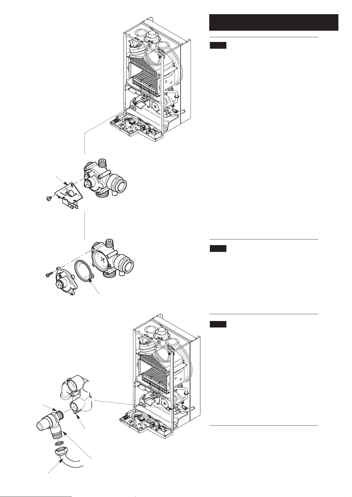
12.0 Changing Components
38
12.21 Central Heating Differential Valve
(Figs. 63 & 64)
1. Drain the primary circuit.
2. Undo the screw securing the microswitch to
the differential valve. Allow the microswitch to
rest to one side.
3. Undo the pressure gauge capillary nut and
heating flow pipe nut from the valve.
4. Prise off the bypass connecting clips and
disconnect the heating flow tap. Undo the screws
securing the valve to the boiler bottom panel.
Remove the valve.
5. Remove the screws securing the cover from
the valve body. Examine the condition of the
diaphragm, spring and pushrod, replacing as
necessary.
6. If required the complete valve assembly can be
replaced.
7. Examine the sealing washers and ‘O’ ring on
the pipes and capillary, replacing as necessary.
12.22 Central Heating Differential Valve
Microswitch (Fig. 64)
1. Remove the two wires from the microswitch.
2. Undo the screw securing the microswitch to
the valve body.
3. Reassemble in reverse order.
12.23 Pressure Relief Valve (Fig. 65)
1. Drain the primary circuit.
2. Disconnect the discharge pipe from the valve.
Using a suitable hexagon key undo the grub
screw sufficiently to release the valve.
3. Note the orientation of the valve, rotate it and
withdraw it from the manifold.
4. Fit the new valve and ‘O’ ring seal and set to
the previously noted orientation. Reassemble in
reverse order.
Microswitch
Bracket
Diaphragm
Fig. 63
Fig. 64
Pressure Relief Valve
Grub Screw
‘O’ ring seal
Discharge Pipe
Fig. 65
Page 39
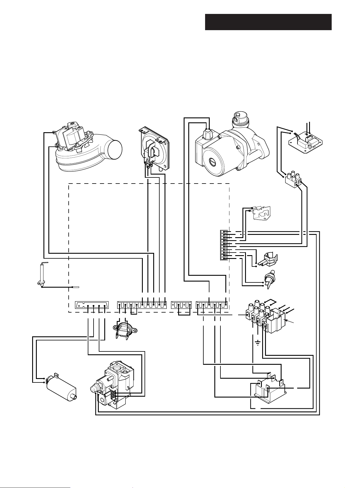
13.0 Illustrated Wiring Diagram
39
- brown
- black
- blue
- red
br
bk
b
r
- green
- green / yellow
- white
g
g/y
w
Return Heating
Temperature Sensor
Reset Selector Switch
Control PCB
A1 A2
A3
A4
A5
F2
1
bk
bk
r
r
g
g
212 3341
1
2
3
4
5
6
7
8
9
10
234 12
36
454
556789
Central Heating
NTC Sensor
Fan
Gas Valve
Overheat Stat
Hydraulic Differential
Pressure Switch
Air Pressure
Switch
Flame
Mains Input
Fuse
Link
g/y
g/y
b
br
bk
br
b
bk
r
g
r
g
Sensing
Electrode
Pump
bb
bbrbb
br
br
b
b
r
bkbrbr
b
br
Spark Generator
Relay Board
Cylinder Stat
Input
N
S/L
Page 40
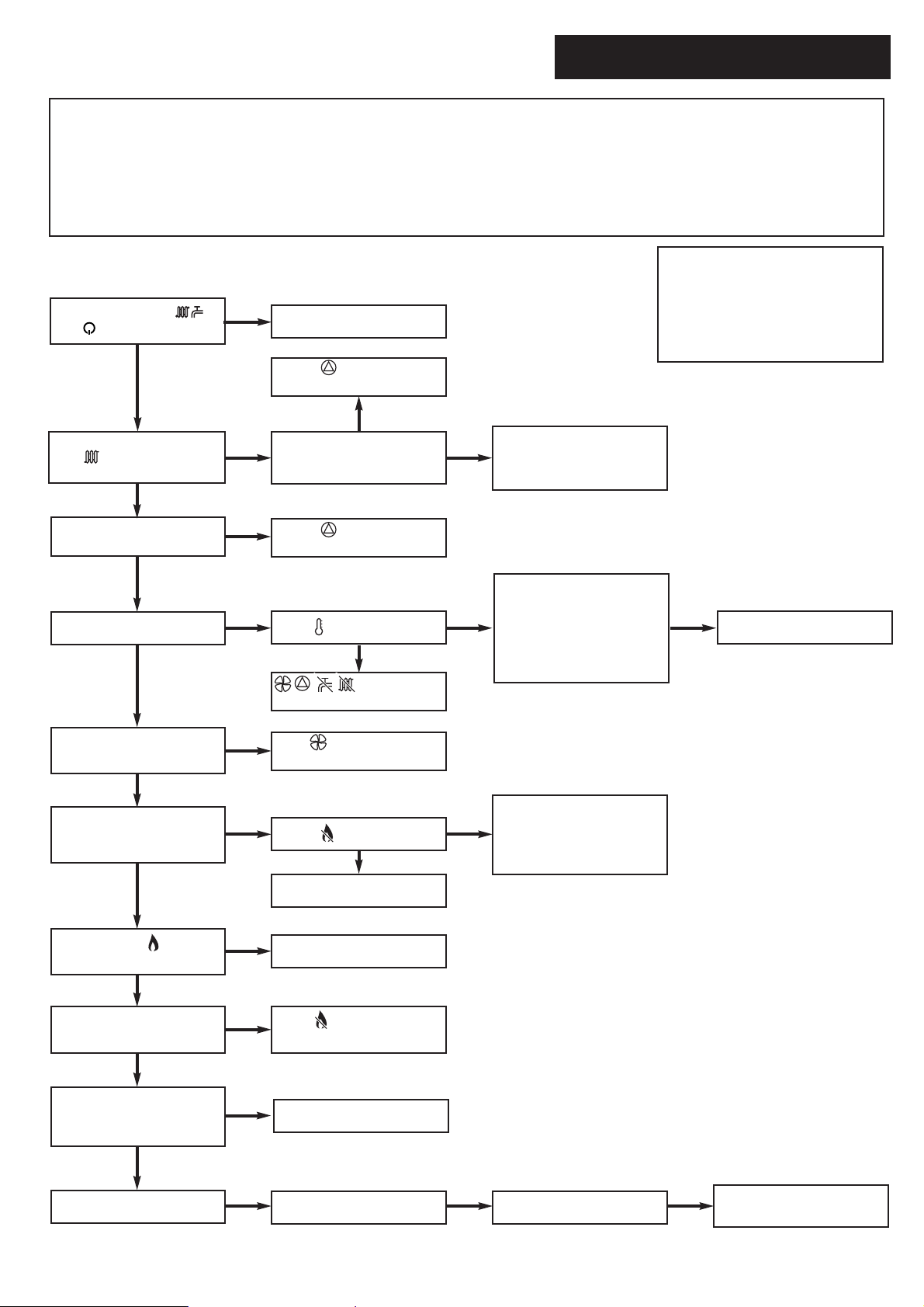
40
14.0 Fault Finding
Carry out initial fault finding checks
1. Check that gas, water and electrical supplies are available at the boiler. Electrical supply = 230V ~ 50 Hz.
CH water system pressurised to 0.5 bar when the boiler is cold. The preferred minimum gas pressure is 19.5mbar (natural gas), 27mbar
(butane) or 36mbar (propane).
2. Carry out electrical system checks, i.e. Ground Continuity, Resistance to Ground, Short Circuit and Polarity with a suitable meter.
NOTE: These checks must be repeated after any servicing or fault finding.
3. Ensure all external controls are calling for heat and check all external and internal fuses. Before any servicing or replacement of parts
ensure the gas and electrical supplies are isolated.
Refer to Section 13.0 “Illustrated Wiring Diagram” for position of numbered terminals
Central Heating - Follow operational sequence
Turn selector to
neon illuminated
Primary flow switch
operated
Fan runs at max speed
Burner goes out
Turn temperature control
to max.
Pump runs
Air pressure
switch proved
neon flashing
Burner on neon
illuminated
Burner output
modulates until set
temperature is reached
Spark at ignition
electrodes for up to 10
seconds
Go to section ‘A’
neon flashing
Go to section ‘B’
neon flashing
Go to section ‘C’
Go to section ‘J’
neons flashing
Go to section ‘D’
neon flashing
Go to section ‘E’
Replace PCB
Turn selector to the reset
position. If the neon does
not extinguish go to
sections ‘H’ & ‘K’
Go to section ‘F’
neon flashing
Go to section ‘I’
Go to section ‘G’
Fan stops Pump stops
Operation sequence
correct
neon flashing
Turn selector to reset
position. If regular
resetting is required or
appliance still does not
operate investigation is
necessary
External controls calling
for heat
Ensure controls are set to
demand and verify the
contacts are closed
Burner extinguishes
after 10 seconds
YES
YES
YES
YES
YES
YES
YES
YES
YES
YES
NO
YES
YES YES YES
NO
NO NO
NO
NO
NO
NO
NO
NO
NO
YES
NO
NOTE: When instructed to turn the
selector to the reset position turn the
selector switch fully anticlockwise
against the spring pressure to
position R and hold for 2 seconds to
reset the boiler.
Page 41
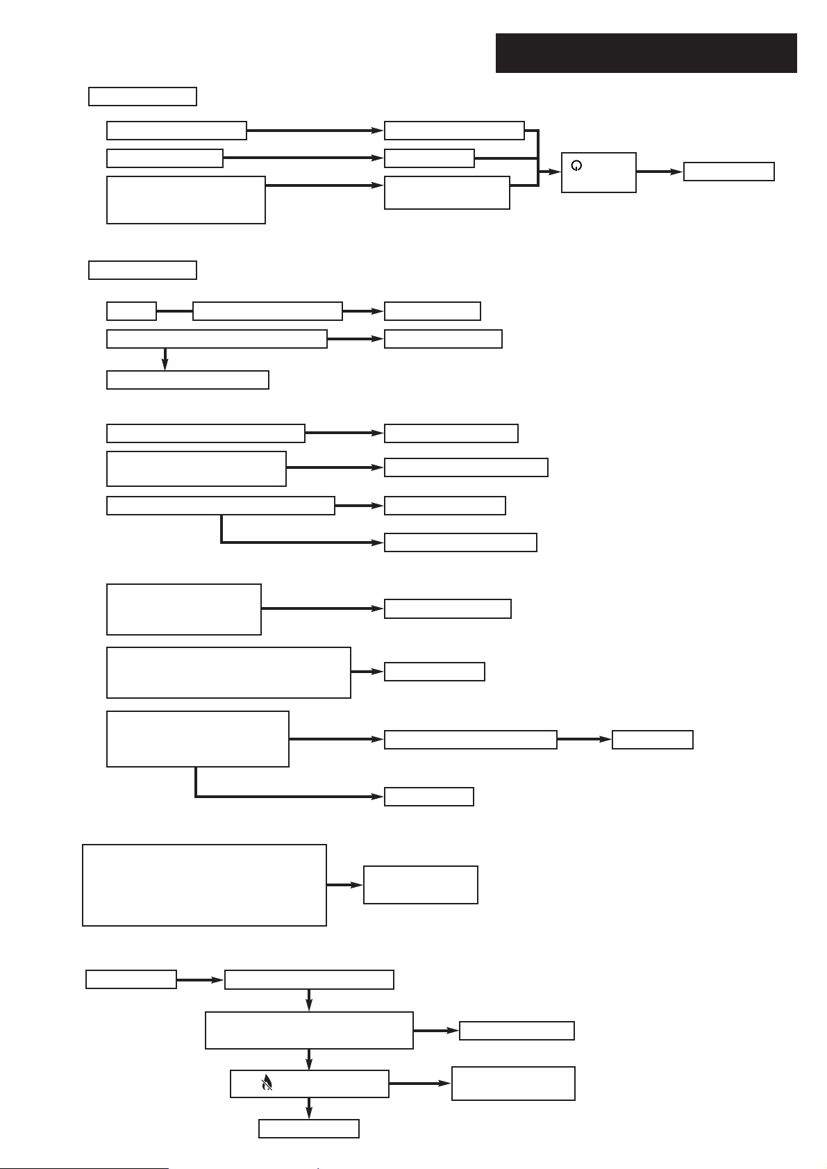
41
14.0 Fault Finding
Fault Finding Solutions Sections A to E
Is there 230V at:
Is there 230V at:
Main terminals L and N Check electrical supply
1.
NO
Main terminal fuse
Replace fuse
Replace PCB
neon
illuminated
2.
YES
Selector terminals a & b
and a & 3. PCB - A4
connector terminals 4 & 5
Check wiring
Replace selector
3.
NO
NO
A
Pump Replace pump
1.
NO
PCB - A4 connector terminals 3 & 6
Replace PCB
2.
NO
Change pump supply cable
YES
B
CH system pressure 0.5 to 1.5 bar Re-pressurise system
1.
NO
Primary flow valve diaphragm damaged
Replace diaphragm
Flow valve rod obstructed
3.
YES
Check the tap of the automatic
air vent is opened
Open the automatic air vent
2.
NO
NO
C
YES
Continuity across flow
microswitch and PCB - A5
connector terminals 7 & 8
Replace microswitch
1.
NO
NO
Primary temperature sensor faulty.
Cold resistance approx. 11K ohms
(resistance reduces with increase in temp.)
Replace sensor
2.
YES
Fan connections correct at fan.
PCB - A2 connector, is 230V
across terminals 5 & 7
Fan jammed or faulty winding
Replace PCB
Replace fan
YES
3.
D
If pump jammed, release
Check and correct if necessary
1. Electrical and pressure tube connections
2. Blockage of pressure tubes
3. Restriction in flue
4. Venturi
NO
E
Replace air
pressure switch
Gas at burner
Ensure gas is on and purged
Replace PCB
Replace gas valve
neon flashing
PCB - A1 connector has 230V AC
across terminals 2 & 4
YES
Turn selector switch
to reset position
R
YES
NO
NO
NO
F
Page 42
42
14.0 Fault Finding
Replace PCB
G
Check and correct if necessary
1. Ignition electrode and lead
2. Electrode connection
3. Spark gap and position
230V at PCB - A1
connector across terminals
3 & 5. Check wiring
YES
NO
Replace igniter
YES
H
YES
Check the burner setting pressure of
the gas valve
(see Section 9.2 of Commissioning)
1.
Voltage at modulating coil of gas valve is:
Max. burner press.approx 9V DC (13V DC LPG)
Min. burner press.approx 1V DC
Current at modulating coil of gas valve is:
(Use an instrument with average function for this
measure)
30 ÷ 230 mA DC (45 ÷ 310 mA DC LPG)
Replace gas valve
NO
Replace PCB
2.
Check and correct if necessary
1. Flame sensing electrode and lead connections
2. Electrode position
Flame current should be 1 µA approx.
Replace PCB
Replace
PCB
YES
YES
Replace flame sensing electrode
NO
YES
Ensure that mains input
terminal L is Live (230V) and
N is Neutral (0V)
I
Check terminal 1 of On/Off/Reset selector is in
connection with PCB - A4 connector terminal 2
Check electrical continuity across terminals 1 & a
of On/Off/Reset selector when turned to position
R
Replace On/Off/Reset selector
NO
Replace PCB
YES
K
Replace safety
thermostat
YES
NO
Overheat thermostat operated
or faulty, i.e. continuity across
thermostat terminals
Allow to cool. Continuity
across thermostat terminals
more than 1.5 ohm
J
Page 43
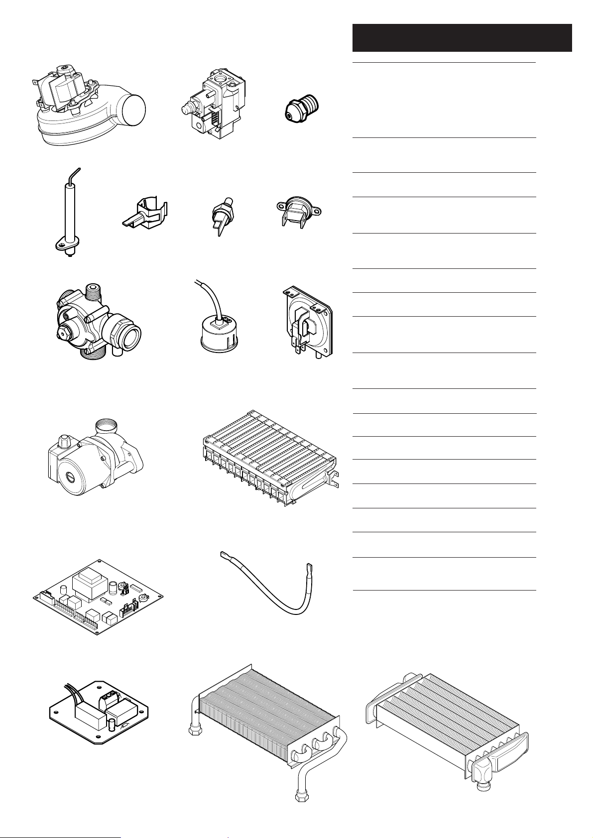
15.0 Short Parts List
43
Short Parts List
Key G.C. Description Manufacturers
No. No. Part No.
22 E66 383 Fan 35/60 248001
E66 527 Fan 60/100 248002
23 393 374 Pressure Switch 247380
32 E66 393 Heat Exchanger 35/60 248016
E66 535 Heat Exchanger 60/100 248017
41 E66 398 Burner 35/60 248029
E66 399 Burner 60/100 248030
44 Injector 248210
59 E66 408 Electrode Lead 248037
63 E66 411 Spark or Sensing
Electrode 247384
72 E66 431 Pump 35/60 248041
E66 539 Pump 60/100 248042
102 Hydraulic Outlet Assy 248490
131 342 571 Temperature Sensor 247394
135 E66 439 Safety Thermostat 248079
140 Gas Valve 5107339
154 PCB 248074
156 DHW Relay PCB 248620
169 E66 453 Pressure Gauge 248090
528 Return Heating 248497
Temperature Sensor
22
140
44
63
102
72
135
59
41
154
32
169
131
528
23
32
35/60 models
60/100 models
156
Page 44

Baxi UK Limited
Brownedge Road
Bamber Bridge Preston
Lancashire
PR5 6SN
www.baxi.com
After Sales Service
08706 096 096
Technical Enquiries
08706 049 049
Comp No248544 - Iss 5 - 7/02
922.553.1
 Loading...