

Baxi Solo 3 PFL 30, Solo 3 PFL 40, Solo 3 PFL 70, Solo 3 PFL 50, Solo 3 PFL 80 Installation & Servicing Instructions Manual
...
© Baxi Heating UK Ltd 2009
Baxi Solo 3 PFL Range
Wall Mounted Powered Flue
Gas Fired Central Heating Units
Installation & Servicing Instructions
These instructions include the Benchmark Commissioning Checklist
and should be left with the user for safe keeping.

© Baxi Heating UK Ltd 2009
2
Natural Gas
Baxi Solo 3 PFL 30
G.C.No. 41 075 20
Baxi Solo 3 PFL 40
G.C.No 41 075 21
Baxi Solo 3 PFL 50
G.C.No. 41 075 22
Baxi Solo 3 PFL 60
G.C.No 41 075 23
Baxi Solo 3 PFL 70
G.C.No. 41 075 24
Baxi Solo 3 PFL 80
G.C.No. 41 075 30
The boiler meets requirements of Statutory Instrument “The Boiler
(Efficiency) Regulations 1993 N
o
3083” and is deemed to meet the
requirements of Directive 92/42/EEC on the efficiency requirements for
new hot water boilers fired with liquid or gaseous fuels:-
Type test for purpose of Regulation 5 certified by:
Notified Body 0086.
Product/Production certified by:
Notified Body 0086.
For GB / IE only.
IMPORTANT - Installation, Commissioning, Service & Repair
This appliance must be installed in accordance with the
manufacturer’s instructions and the regulations in force. Read the
instructions fully before installing or using the appliance.
In GB, this must be carried out by a competent person as stated
in the Gas Safety (Installation & Use) Regulations.
Definition of competence: A person who works for a Gas Safe
registered company and holding current certificates in the
relevant ACS modules, is deemed competent.
In IE, this must be carried out by a competent person as stated in
I.S. 813 “Domestic Gas Installations”.
Lifting - This product should be lifted and handled by two
people. Stooping should be avoided and protective
equipment worn where necessary. Carrying & lifting
equipment should be used as required, e.g. when installing in
a loft space.
Codes of Practice, most recent version should be used
In GB the following Codes of Practice apply:
Standard Scope
BS 6891 Gas Installation.
BS 5546 Installation of hot water supplies for
domestic purposes.
BS 5449 Part 1 Forced circulation hot water systems.
BS 6798 Installation of gas fired hot water boilers.
BS 5440 Part 1 Flues.
BS 5440 Part 2 Ventilation.
BS 7593 Treatment of water in domestic hot water
central heating systems.
BS 4814 Expansion vessels for hot water systems.
BS 6283 Safety and control devices for use in hot
water systems.
In IE the following Codes of Practice apply:
Standard Scope
I.S. 813 Domestic Gas Installations.
The following BS standards give valuable additional information;
BS 5546 Installation of hot water supplies for
domestic purposes.
BS 5449 Part 1 Forced circulation hot water systems.
BS 7593 Treatment of water in domestic hot water
central heating systems.
IMPORTANT - The addition of anything that may interfere
with the normal operation of the appliance without express
written permission from the manufacturer or his agent
could invalidate the appliance warranty. In GB this could
also infringe the G
AS SAFETY (Installation and Use)
R
EGULATIONS.
© Baxi Heating UK Ltd 2009 All rights reserved. No part of this publication may be
reproduced or transmitted in any form or by any means, or stored in any retrieval system of
any nature (including in any database), in each case whether electronic, mechanical, recording
or otherwise, without the prior written permission of the copyright owner, except for
permitted fair dealing under Copyrights, Designs and Patents Act 1988.
Applications for the copyright owner’s permission to reproduce or make other use of any
part of this publication should be made, giving details of the proposed use, to the following
address:
The Company Secretary, Baxi Heating UK Ltd, The Wyvern Business Park,
Stanier Way, Derby, DE21 6BF.
Full acknowledgement of author and source must be given.
WARNING: Any person who does any unauthorised act in relation to a copyright work may
be liable to criminal prosecution and civil claims for damages.
0086
ISO 9001
FM 00866
All Gas Safe registered engineers carry an ID card with their
licence number and a photograph. You can check your engineer
is registered by telephoning 0800 408 5500 or online at
www.GasSafeRegistered.co.uk
The Benchmark Scheme
Benchmark places responsibilities on both manufacturers and installers. The purpose is to
ensure that customers are provided with the correct equipment for their needs, that it is
installed, commissioned and serviced in accordance with the manufacturer’s instructions by
competent persons and that it meets the requirements of the appropriate Building
Regulations. The Benchmark Checklist can be used to demonstrate compliance with Building
Regulations and should be provided to the customer for future reference.
Installers are required to carry out installation, commissioning and servicing work in
accordance with the Benchmark Code of Practice which is available from the Heating and
Hotwater Industry Council who manage and promote the Scheme. Visit
www.centralheating.co.uk for more information.
© Baxi Heating UK Ltd 2009
3
1.0 Introduction 4
2.0 Technical Data 5
3.0 System Details 7
4.0 Site Requirement 10
5.0 Installation 14
6.0 Commissioning the Appliance 32
7.0 Fitting the Outercase 34
8.0 Overheat Cut-Off Device 35
9.0 Annual Servicing 36
10.0 Changing Components 38
11.0 Fault Finding 42
12.0 Short Parts List 44
13.0 Notes 45
Section Page
Contents
© Baxi Heating UK Ltd 2009
Model Heat Output
30 8.79kW (30,000 Btu/h)
40 11.72kW (40,000 Btu/h)
50 14.65kW (50,000 Btu/h)
60 17.58kW (60,000 Btu/h)
70 20.5kW (70,000 Btu/h)
80 23.44kW (80,000 Btu/h)
1.0 Introduction
4 1
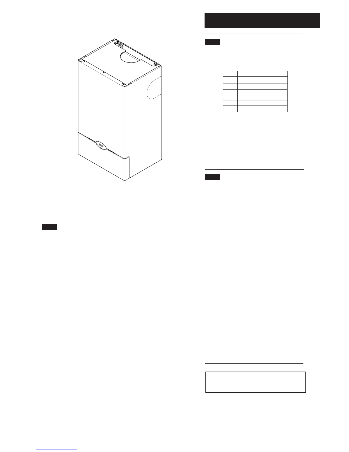
1.1 Description
1. The Baxi Solo 3 PFL is a gas fired room sealed fan
assisted central heating boiler with outputs as shown in
the table below
2. Each appliance is preset at a heat input rating and is
designed for use on NATURAL GAS only.
3. All boilers are suitable for fully pumped open vented
central heating and domestic hot water systems and
sealed systems.
4. The appliance data badge is fitted to the combustion
box door.
1.2 Installation
The appliance is suitable only for installation in GB and
IE and should be installed in accordance with the rules in
force.
In GB, the installation must be carried out by a Gas
Safe Registered Installer. It must be carried out in
accordance with the relevant requirements of the:
• Gas Safety (Installation & Use) Regulations.
• The appropriate Building Regulations either The
Building Regulations, The Building Regulations
(Scotland), Building Regulations (Northern Ireland).
• The Water Fittings Regulations or Water Byelaws in
Scotland.
• The Current I.E.E. Wiring Regulations.
Where no specific instructions are given, reference
should be made to the relevant British Standard Code
of Practice.
In IE, the installation must be carried out by a
competent Person and installed in accordance with the
current edition of I.S. 813 ‘Domestic Gas Installations’,
the current Building Regulations and reference should
be made to the current ETCI rules for electrical
installation.
Read the instructions before installing or using this
appliance.
All systems must be thoroughly flushed and treated
with inhibitor (see Section 3.1).
1.3 Important Information
Man-Made Mineral Fibre
a) Some component parts of this appliance (insulation pads, gaskets and rope
seals) are manufactured from man-made mineral fibre.
b) Prolonged or excessive exposure to this material may result in some irritation
to the eyes, skin or respiratory tract.
c) It is advisable to wear gloves when handling these items.
d) Irritant dust will only be released from the items if they are broken up or
subjected to severe abrasion. In these instances a suitable dust mask and goggles
should be worn.
e) Always thoroughly wash hands after installation, servicing or changing
components.
f) When disposing of any items manufactured from man-made mineral fibre care
must be exercised.
g) If any irritation of the eyes or severe irritation of the skin is experienced seek
medical attention.
IMPORTANT: State of adjustment - Check that the
state of adjustment given on the data plate is
compatible with local supply conditions.

© Baxi Heating UK Ltd 2009
2.0 Technical Data
1 5
Model 30 40 50 60 70 80
P Heat Output kW 8.79 11.72 14.65 17.58 20.5 23.44
Btu/h 30,000 40,000 50,000 60,000 70,000 80,000
Q Heat Input kW 10.99 14.65 18.32 21.98 25.64 29.31
Btu/h 37,500 50,000 62,500 75,000 87,500 100,000
Burner Pressure mbar 16.0 ±0.5 16.0 ±0.5 16.0 ±0.5 16.0 ±0.5 16.0 ±0.5 16.0 ±0.5
in wg 6.4 ±0.2 6.4 ±0.2 6.4 ±0.2 6.4 ±0.2 6.4 ±0.2 6.4 ±0.2
Gas Rate CV 38mj/m
3
1.04m3/h 1.39m3/h 1.74m3/h 2.08m3/h 2.43m3/h 2.78m3/h
(after 10 mins) 36.86ft3/h 49.0ft3/h 61.3ft3/h 73.5ft3/h 86.75ft3/h 99.24ft3/h
Lifting Weight kg 23.1 23.1 23.1 32.2 32.2 32.2
lbs 51 51 51 71 71 71
Water Content litres 1.1 1.1 1.1 1.6 1.6 1.6
pints 1.9 1.9 1.9 2.8 2.8 2.8
Outercase Height 600mm 600mm 600mm 600mm 600mm 600mm
Dimensions Width 350mm 350mm 350mm 462mm 462mm 462mm
Depth 287mm 287mm 287mm 287mm 287mm 287mm
Flue Terminal Diameter 100mm
Dimensions Depth 70mm
Static Head Max 30 metres (100 ft)
Min 1 metre (3.25 ft)
Connections Flow 22mm Cu tail
Return 22mm Cu elbow
Heat Exchanger Cast iron monobloc
Low Head Min 0.2m (8 in)
System Design fully pumped open vented and sealed systems
Gas Connection RC1/2(1/2in BSPT)
Electrical Supply 230V ~ 50Hz fused 5A - 90W
Controls boiler thermostat, intermittent pilot & electronic flame sensing
timed pump over-run, frost protection thermostat
Internal Fuse 4AF 250V to BS4256 situated on control board
© Baxi Heating UK Ltd 2009
2.0 Technical Data
6
25
75
121
392
439
442
268
144144
4
107 Dia
without
internal
fitting
117 Dia
with
internal
fitting
Centre of
Gas Connection
8 Slots
20 x 6
Layout of Fixing Points
30, 40 and 50 models
25
75
121
392
439
442
380
196196
52
107 Dia
without
internal
fitting
117 Dia
with
internal
fitting
Centre of
Gas Connection
8 Slots
20 x 6
Layout of Fixing Points
60, 70 and 80 models
(4) 10
(8) 20
(16) 40
(24) 60
(12) 30
(20) 50
(28) 70
(32) 80
(36) 90
(40) 100
(44) 110
(48) 120
2 4 6 8 1012 141618 2022
Water Flow Rate litres / min
Pressure Drop mbar (in wg)
2426 28 30
(52) 130
(4) 10
(8) 20
(16) 40
(24) 60
(12) 30
(20) 50
(28) 70
(32) 80
(36) 90
(40) 100
(44) 110
(48) 120
2 4 6 8 1012 141618 2022
Water Flow Rate litres / min
Pressure Drop mbar (in wg)
2426 28 30
(52) 130
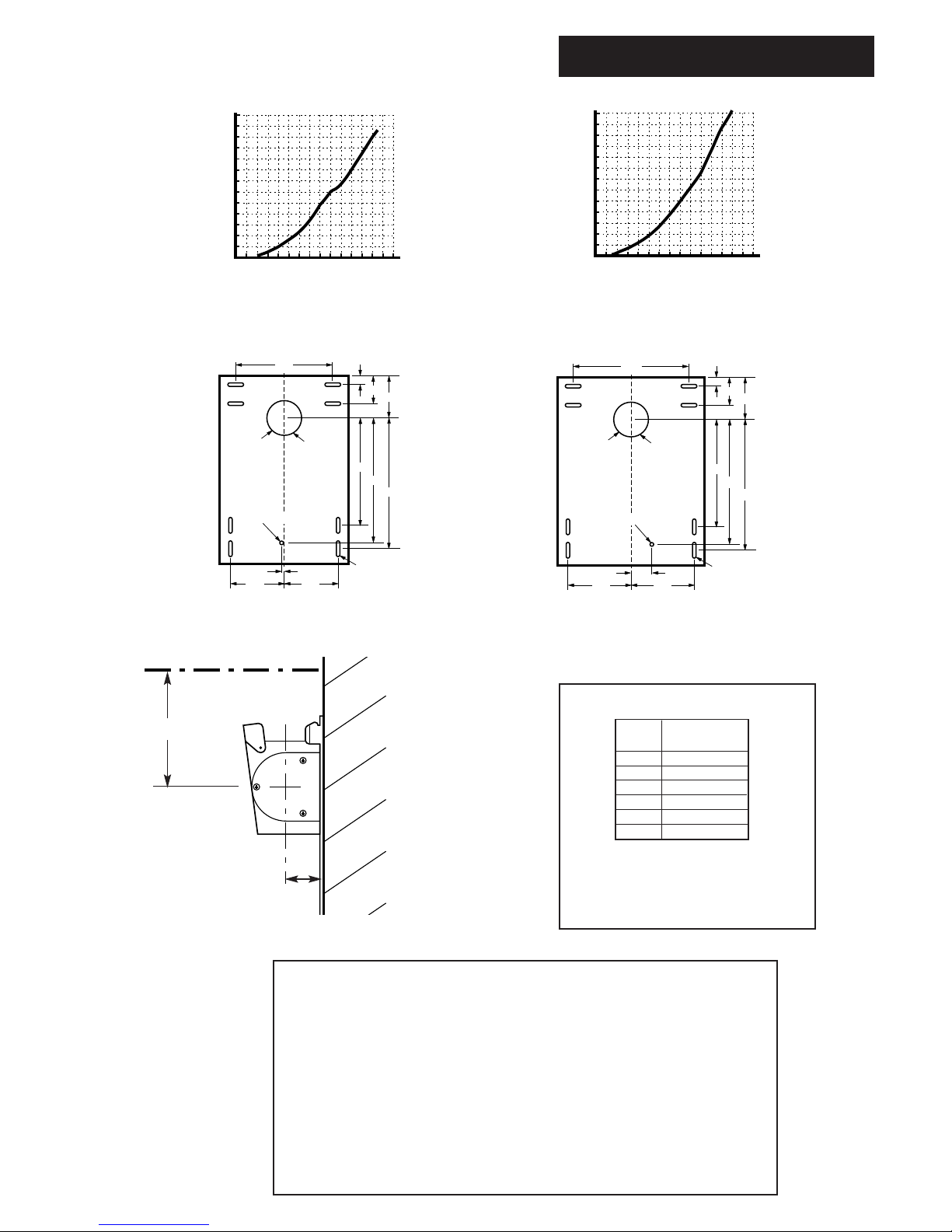
30, 40 and 50 models
60, 70 and 80 models
Templates
Hydraulic Resistance Charts
• This appliance is only intended for installation on a governed supply.
• PMS = 3 bar pressure class 2
• Max CH water pressure 3 bar
• Type C
12,C32, C52
• Nox class 1
• Appliance category I
2H
2H - G20 - 20mbar
• Ref: 86/AU/588
• Burner Injector Sizes: 30=B12 40=B13 50=B14 60=B15 70=B30 80=B16
• This boiler is designed to operate at a maximum water temperature of 85° C.
61.3mm
Model Seasonal Efficiency
(SEDBUK) (%)
30 79.4
40 78.4
50 78.0
60 78.5
70 78.2
80 79.0
This value is used in the UK Government’s Standard
Assessment Procedure (SAP) for energy rating of dwellings.
The test data from which it has been calculated have been
certified by 0086.
SEDBUK Declaration For Solo 3 PFL
All Models
121mm
Top of Outercase
© Baxi Heating UK Ltd 2009
3.0 System Details
7
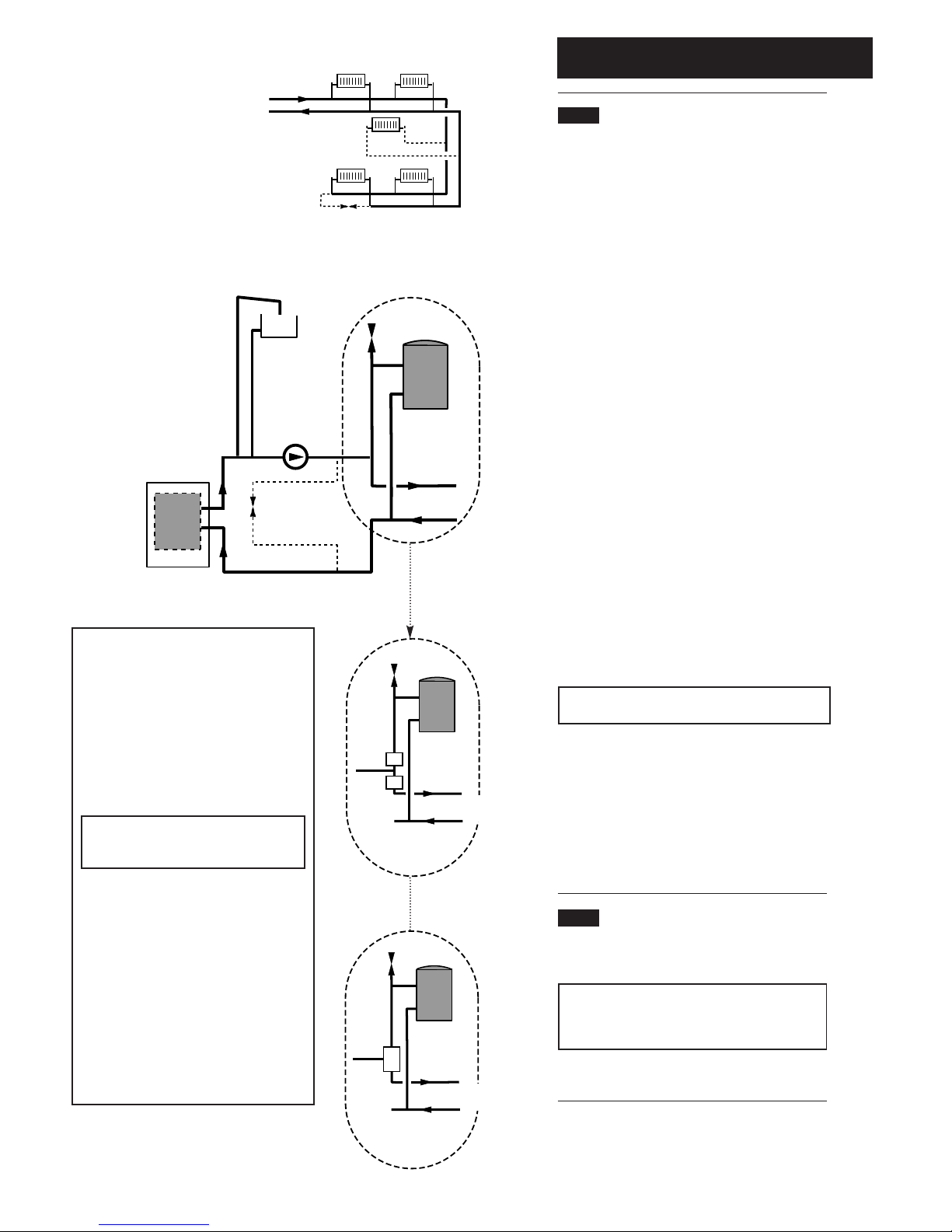
Typical Systems
Arrangement
Option A
Boiler
Pump
Air Vent
Radiator
Circuit
Fully Pumped System
Air
Vent
Radiator
Circuit
Twin Zone
Valve System
Air
Vent
Radiator
Circuit
3 Port Divertor
Valve System
Option B
Radiator Circuit
Option C
Fig. 1
Fig. 2
Fig. 3
Fig. 4
Examples of systems which require a bypass
are:-
a) A system controlled by non-electrical valves
e.g. mechanical thermostatic control valves both
on the radiators and the hot water circuit.
b) A system using twin zone valves (e.g.
Honeywell 'S' Plan) (Fig. 3).
c) A system using a 3 port divertor valve (Fig. 4)
does not normally require a bypass therefore this
system is recommended. The exception to this is
where thermostatic radiator valves are used and
then a bypass is required.
NOTE: For ‘S’ Plan systems the bypass flow
circuit must be situated between pump and
zone valves as option A shows (Fig. 2).
The bypass circuit can be:-
a) For all boilers a minimum of 6 metres of
22mm copper pipe, (measured between the
boiler flow and return connections). It should be
fitted with a lock shield valve opened at least 1
full turn or a proprietary bypass valve set to give
a minimum flow rate of 8 litres/min (1.8 gal/min)
(Option C, Fig. 1 & Option A, Fig.2).
b) A radiator fitted with lock shield valves. The
radiator output should be a minimum of 800
watts (2,700 Btu/h). Typically a convector type
radiator with an area of 3750 cm
2
(4 sq ft) is
adequate (Option B, Fig. 1).
c) Any circuit that provides the same operating
conditions as option A or option B (Figs. 1 & 2).
3.1 Water Circulating Systems
1. The appliance is suitable for use with open vent fully
pumped systems and sealed systems where additional
control protection is required.
The following conditions should be observed on all
systems:
• The static head must not exceed 30m (100ft) of water.
• The boiler must not be used with a direct cylinder.
• The boiler is fitted with a timed pump overrun that will
operate for approximately 8 minutes.
• Drain cocks should be fitted to all system low points.
• All gas and water pipes and electrical wiring must be
installed in a way which would not restrict the servicing of
the boiler.
• Position isolating valves as close to circulating pump as
possible.
Treatment of Water Circulating Systems
All recirculatory water systems will be subject to
corrosion unless they are flushed and an appropriate
water treatment is applied. To prevent this, follow the
guidelines given in BS 7593 “Treatment of Water in
Domestic Hot Water Central Heating Systems” and the
treatment manufacturers instructions.
Treatment must involve the use of a proprietary
cleanser, such as Sentinel X300 or X400, or Fernox F3
and an inhibitor such as Sentinel X100 or Fernox MB-1.
Full instructions are supplied with the products, for
further information contact Sentinel (0800 389 4670) or
Fernox (0870 870 0362).
Failure to flush and add inhibitor to the system will
invalidate the appliance warranty.
It is important to check the inhibitor concentration after
installation, system modification and at every service in
accordance with the inhibitor manufacturer’s
instructions. (Test kits are available from inhibitor
stockists.)
For information or advice regarding any of the above
contact Technical Enquiries 0844 871 1555.
3.2 Bypass Requirements
1. The boiler is fitted with a pump overrun device which
allows the removal of residual heat from the boiler.
NOTE: The pump overrun will operate for
approximately 8 minutes. The system design must
therefore, always provide an open circuit for water to
circulate between the boiler flow and return.
2. See information opposite “Examples of systems which
require a bypass are”.
© Baxi Heating UK Ltd 2009
3.0 System Details
8
3.3 Pipework
1. If this appliance is being fitted to a system containing
plastic pipework, the flow switch kit part n
o
5107297
must be fitted.
2. The sizes of flow and return pipes from the boiler
should be determined by normal methods, according to
the requirements of the system.
3. An 11 °C (20°F) drop in temperature across the
system is recommended.
4. In systems using non-metallic pipework it is necessary
to use copper pipe for the boiler Flow and Return. The
copper must extend at least 1 metre from the boiler and
include any branches (Fig. 5). The copper pipe must not
be insulated.
3.4 System Controls
1. For optimum operating conditions, the heating system
into which the boiler is installed should include a control
system.
2. Such a system will comprise of a timer control and
separate room or cylinder thermostats as appropriate.
3. The boiler should be controlled so that it operates on
demand only.
4. Operation of the system under control of the boiler
thermostat only does not produce the best results.
5. A frost thermostat is fitted integrally to the appliance
controls and will protect the boiler from frost damage by
operating the burner when the water temperature in the
boiler drops towards freezing point. The boiler will fire
as necessary to maintain a temperature above freezing.
NOTE: The frost thermostat operates even if the boiler
thermostat is in the OFF ('0') position and it is necessary
therefore, if the system is drained, for the external
electrical and gas supplies to be isolated. It is
recommended that a label be affixed to the appliance to
draw attention to the fact that the system has been
drained.
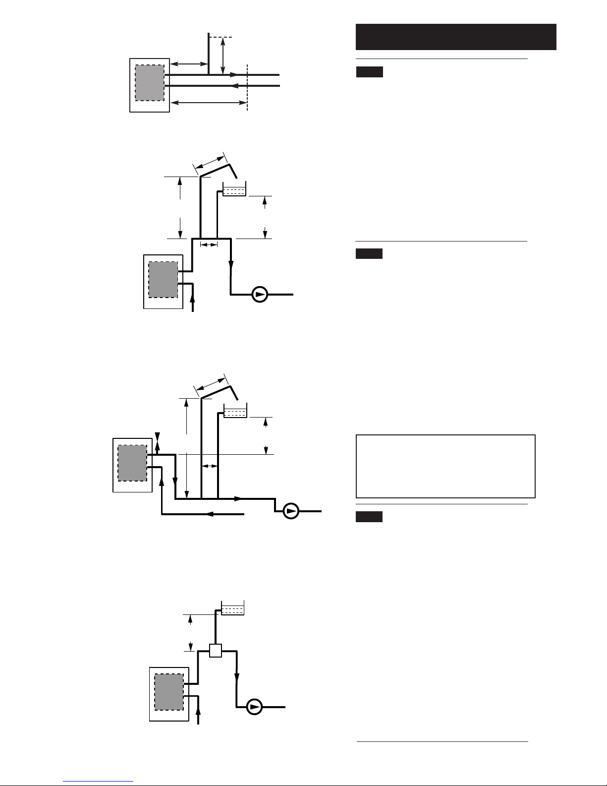
3.5 Low Head Installation
For boilers up to 50,000 Btu/h output
1. Using a close coupled arrangement the minimum head
is as shown in the diagrams
(Figs. 6 & 7) subject to the following conditions:
a) The correct heat input.
b) The pump being adjusted to give an 11
o
C drop
across the boiler.
c) The pump must be fitted on the flow.
d) The pump must be fitted in accordance with the
pump manufacturer's instructions.
e) The open vent pipe must be taken up from a tee in
a horizontal section of the flow pipe.
Alternative Low Head Installation for all Solo 3 PFL
(Fig. 8)
2. If less height is available then a combined vent and
feed pipe may be connected. This must be a minimum
of 22mm diameter. It is recommended that an air
separator is fitted when using a combined feed and vent
pipe.
Typical Low Head Installation
If Conditions Require,
This System Possible
Alternative Low Head Installation
Boiler
500mm
45°
22mm
Open Vent
1000mm
Min
150mm
Max
15mm
Cold
Feed
400mm
Min Head
Return
Pump
Flow
Boiler
500mm
45°
22mm
Open Vent
400mm
Min Head
1000mm
Min
Automatic Air
Vent
15mm
Cold
Feed
150mm
Max
Return
Pump
Flow
Return
Pump
Flow
Boiler
200mm
Min
Air
Separator
22mm
Feed & Vent
Pipe
Fig. 6
Fig. 7
Fig. 8
Boiler
Flow
Return
Copper
0.5m
Copper
1m
Copper
0.5m
Fig. 5
© Baxi Heating UK Ltd 2009
3.0 System Details
9
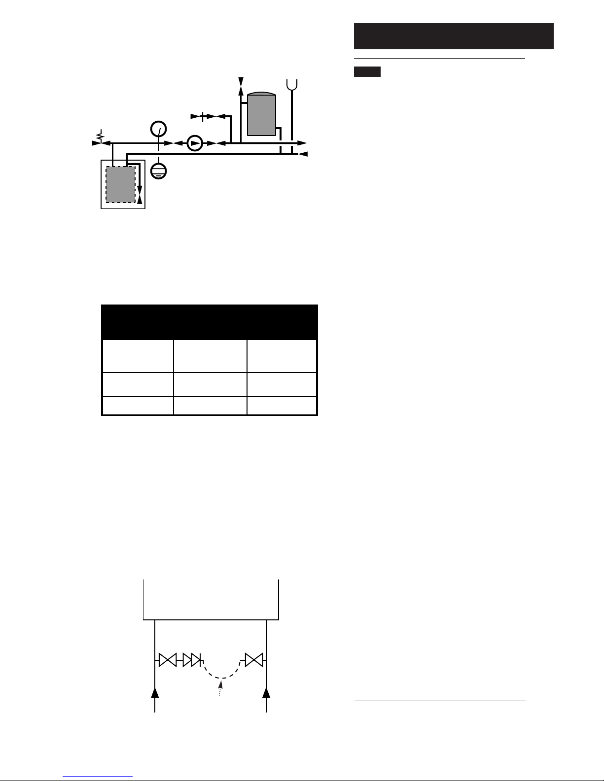
3.6 Sealed Systems (Fig. 9)
1. SAFETY VALVE - A safety valve complying with the
requirements of BS 6283 Part 1 must be fitted close to the
boiler on the flow pipe by means of a horizontal or vertically
upward connection with no intervening valve or restrictions
and should be positioned to facilitate testing. The valve should
be pre-set and non-adjustable to operate at a pressure of 3
bar (45 Ibf/in2). It must be arranged to discharge any water or
steam through a pipe to a safe outlet position.
2. PRESSURE GAUGE - A pressure gauge of minimum range
0-4 bar (0-60 Ibf/in
2
) with a fill pressure indicator must be
fitted to the system, preferably at the same point as the
expansion vessel in an easily visible position.
3. EXPANSION VESSEL - An expansion vessel complying with
the requirements of BS 4814 must be fitted to the system by
means of a connection close to the inlet side of the circulating
pump in accordance with the manufacturers instructions, the
connecting pipe being unrestricted and not less than 15mm (1/
2
in) nominal size. The volume of the vessel should be suitable
for the system water content and the nitrogen or air charge
pressure should not be less than the system static head (See
Table. 1).
Further details of sealed system design can be obtained from
BS 5449 and the British Gas publication entitled 'Specifications
for Domestic Wet Central Heating Systems'.
4. FILLING POINT - A filling point connection on the central
heating return pipework must be provided to facilitate initial
filling and pressurising and also any subsequent water loss
replacement / refilling.
The sealed primary circuits may be filled or replenished by
means of a temporary connection between the circuit and a
supply pipe, provided a ‘Listed’ double check valve or some
other no less effective backflow prevention device is
permanently connected at the inlet to the circuit and the
temporary connection is removed after use.
The filling method adopted must be in accordance with all
relevant water supply regulations and use approved
equipment.
Your attention is drawn to, for GB: Guidance G24.2 and
recommendation R24.2 of the Water Regulations Guide. for
IE: the current edition of I.S. 813 “Domestic Gas Installations”.
5. MAKE UP SYSTEM - A method of replacing water lost from
the system should be provided either by means of a make up
vessel of not more than 3 litres
(5 pints) capacity, mounted above the highest point of the
system, or by pre-pressurisation of the system.
6. VENTING - A method of venting the system during filling
and commissioning must be provided by fitting automatic air
vents or by venting manually.
7. HOT WATER STORAGE - The hot water storage vessel
must be of the indirect coil type.
8. SYSTEM COMPONENTS - All components used in the
system must be suitable for operation at 110°C (230°F) and at
the pressure allowed by the safety valve.
Initial System
Pressure (Bar)
Vessel Charge
Pressure (Bar)
Multiply Total
Water Content Of
System By (Litres)
0.067
0.112
0.207
0.441
0.087
0.152
0.330
0.125
0.265
0.5
1.0
1.5
2.0
1.0
1.5
2.0
1.5
2.0
0.5
1.0
1.5
Example :-
Then :-
System Volume = 75 litres
Vessel Charge Pressure = 1.0 bar
Initial System Pressure = 1.5 bar
75 x 0.152 = 11.4 litres
Expansion Vessel Volume
Method of determining minimum
value of expansion vessel volume for
sealed systems using Baxi Boilers
NOTE
Where a vessel of the calculated size is not obtainable
then the next available larger size should be used.
Safety
Valve
Pressure
Gauge
Pump
Filling
Point
Air
Vent
3 Litre
Top Up Bottle
(if required)
Radiator
Circuit
Expansion
Vessel
System Drains at
Low Point
Max Boiler Flow
Temp = 82° C
Boiler
Fig. 9
Table. 1
Stop
Valve
Double
Check
Valve
DHW
Mains
Inlet
CH
Return
Temporary
Hose
Stop
Valve
Fig. 9a
© Baxi Heating UK Ltd 2009
4.0 Site Requirements
10
4.1 Location
1. The appliance may be fitted to any suitable wall with the
flue passing through an outside wall and discharging to
atmosphere in a position permitting satisfactory removal of
combustion products and providing an adequate air supply.
The appliance should be fitted within the building unless
otherwise protected by a suitable enclosure ie. garage or
outhouse. (The appliance may be fitted inside a cupboard,
see section 4.5.)
2. If the appliance is fitted in a room containing a bath or
shower reference must be made to the relevant
requirements.
In GB this is the current I.E.E. Wiring Regulations and
Building Regulations.
In IE reference should be made to the current edition of I.S.
813 “Domestic Gas Installations” and the current ETCI
rules.
3. If the appliance is to be fitted into a building of timber
frame construction then reference must be made to the
current edition of Institution of Gas Engineers Publication
IGE/UP/7 (Gas Installations in Timber Framed Housing).
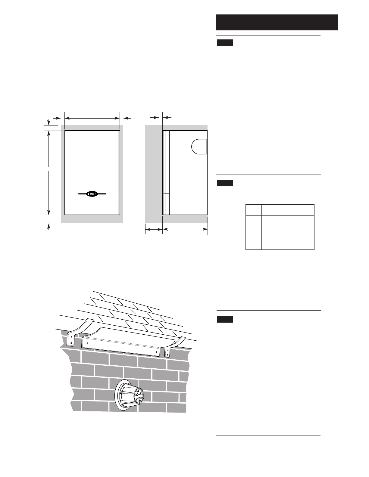
4.2 Minimum Clearances (Fig. 10)
1. A flat vertical area is required for the installation of the
boiler measuring as shown in the table below for each model.
2. These dimensions include the necessary clearances around
the appliance for case removal, spanner access and air
movement. Additional clearances may be required for the
passage of pipes around local obstructions such as joists
running parallel to the front face of the appliance.
3. If fitted inside a cupboard the clearance of 300mm shown
is only necessary when the cupboard door is open. A
clearance of 5mm (3/16in) is required when the door is
closed.
4.3 Flue Position
1. For installations where the flue terminal is inaccessible from
the outside, an internal fitting kit is available. This can be
obtained free of charge from your local merchant.
2. The following guidelines indicate the general requirements
for siting balanced flue terminals.
For GB recommendations are given in BS 5440 Pt. 1.
For IE recommendations are given in the current edition of
I.S. 813 “Domestic Gas Installations”.
3. If the terminal is fitted within 1 metre (39in) of a plastic
gutter, within 500mm (19
1
/2in) of a painted eave or a painted
gutter, an aluminium shield of at least 1 metre (39in) long
should be fitted to the underside of the gutter or painted
surface. An air space of 5mm (3/16in) should be left between
shield and gutter (Fig. 11).
4. If the terminal discharges onto a pathway or passageway,
check that combustion products will not cause a nuisance
and that the terminal will not obstruct the passageway.
Fig. 10
Fig. 11
300mm for servicing
5mm during operation
5mm5mm
350mm (30,40,50 models)
600mm
50mm
100mm
462mm (60,70,80 models)
Aluminium
Shield
Model
Height Width
mm (in) mm (in)
30 750 (291/2) 360 (141/8)
40 750 (291/2) 360 (141/8)
50 750 (291/2) 360 (141/8)
60 750 (291/2) 472 (185/8)
70 750 (291/2) 472 (185/8)
80 750 (291/2) 472 (185/8)
287mm
© Baxi Heating UK Ltd 2009
4.0 Site Requirements
11
4.3 Flue Position (Cont)
WARNING - The addition of anything that may
interfere with the normal operation of the appliance
without the express written permission from the
manufacturer or his agent could invalidate the
appliance warranty and infringe the GAS SAFETY
(Installation and Use) REGULATIONS.
If a terminal is less than 2 metres above a balcony,
above ground or above a flat roof to which people
have access then a suitable terminal guard must be
provided.
5. If the outer surface of an outside wall is of combustible
material, it should be protected by fitting the flue trim
provided.
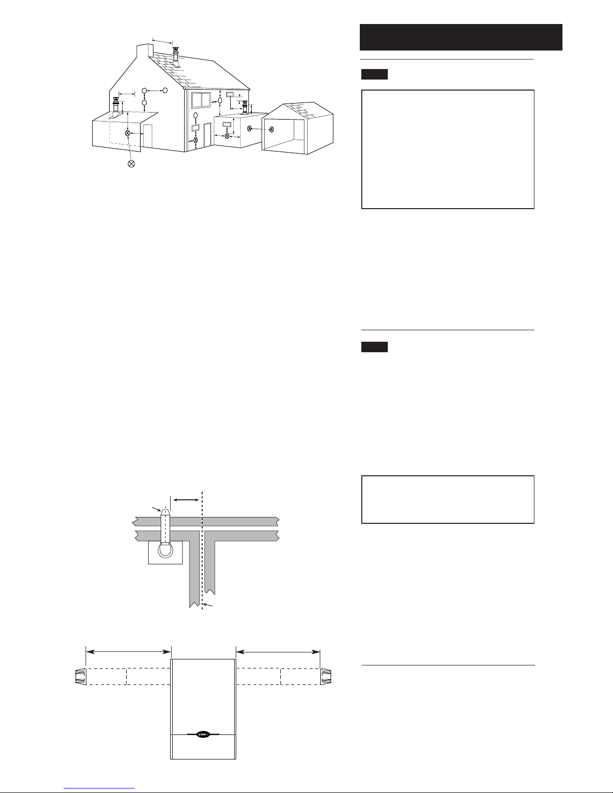
6. Table 2 and Fig. 12 show the positioning of the flue
terminal relative to buildings and other structures.
7. The dimensions of the flue terminal are shown on
page 5.
4.4 Flue Dimensions
1. Flue extensions are available as optional extras for
installations up to 3 metres.
2. Vertical flue kits are available up to 4 metres in
length. Vertical twin flue kits are available up to 15
metres in length.
3. The standard telscopic flue is suitable for use with
rear flue lengths between 100 mm and 500 mm.
NOTE: Maximum flue length when flued to the left
or right is
410 mm - 30, 40, 50 models
355 mm - 60, 70, 80 models
4. Where it is intended to pass the flue through a
combustible wall or timber framed dwelling, reference
should be made to the Institution of Gas Engineers
Publication IGE/UP/7 (Gas Installations in Timber
Framed Housing).
5. If the flue is more than 1 metre long, it is required
that it is supported.
6. All above dimensions are taken from the
respective faces of the outer case.
Table. 2
Fig. 13
Fig. 12
Maximum lengths for side flues using the standard telescopic flue kit
410mm (30, 40, 50)
410mm (30, 40, 50)
355mm (60, 70, 80) 355mm (60, 70, 80)
Terminal Position with Minimum Distance (mm)
AaDirectly below an opening, air brick, opening
windows, etc. 300
BaAbove an opening, air brick, opening window etc. 300
CaHorizontally to an opening, air brick, opening window etc. 300
D Below gutters, soil pipes or drain pipes. 25
E Below eaves. 25
F Below balconies or car port roof. 25
G From a vertical drain pipe or soil pipe. 25
H From an internal
(i)
or external
(ii)
corner.
(i)
25
(ii)
115
I Above ground, roof or balcony level. 300
J From a surface facing a terminal. 600
K From a terminal facing a terminal. 1200
L From an opening in carport (e.g. door, window)
into the dwelling. 1200
M Vertically from a terminal on the same wall. 1500
N Horizontally from a terminal on the same wall. 300
R From adjacent wall to flue (vertical only). 1500
S From an adjacent opening window (vertical only). 300
N
I
I
G
F
M
I
A
A
F
H
J,K
D
E
H
Likely flue positions requiring
a flue terminal guard
C
R
A
I
J,K
I
L
S
B
300 min
Terminal
Assembly
Top View Rear Flue
Property Boundary Line
NOTE: The distance from a fanned draught appliance terminal installed parallel
to a boundary may not be less than 300mm in accordance with the diagram
below.
a
In addition, the terminal should be no nearer than 150 mm to an
opening in the building fabric formed for the purpose of accomodating
a built-in element such as a window frame. See BS 5440 Pt. 1.
© Baxi Heating UK Ltd 2009
4.0 Site Requirements
12
4.5 Ventilation of Compartments
1. Where the appliance is installed in a cupboard or
compartment, no air vents are required. The Solo 3
PFL will run sufficiently cool without ventilation.
NOTE: The ventilation label on the front of the
outer case MUST NOT BE REMOVED when the
appliance is installed in a compartment or
cupboard.
2. B.S. 5440 refers to room sealed appliances installed
in compartments.
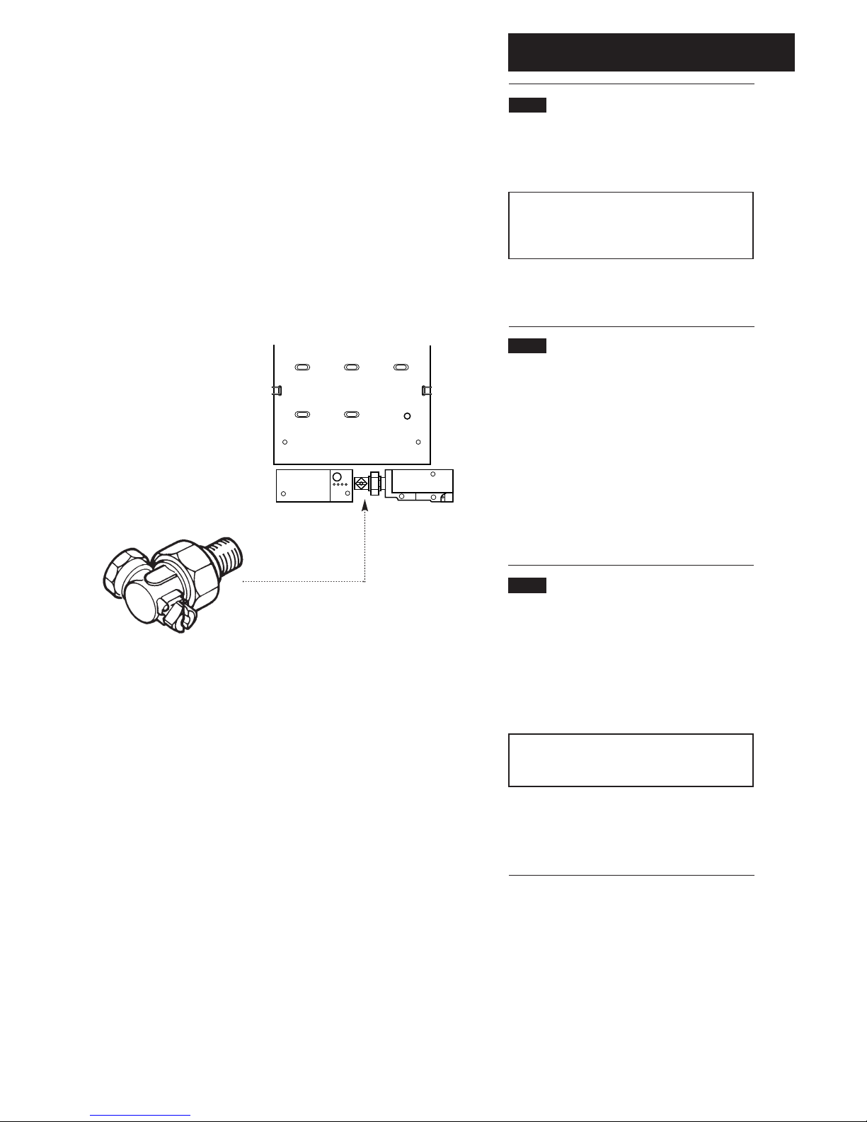
4.6 Gas Supply (Fig. 14)
1. The gas installation should be in accordance with the
relevant standards. In GB this is BS 6891. In IE this is
the current edition of I.S. 813 “Domestic Gas
Installations”.
2. The connection of the appliance is a RC
1
/2(1/2in
BSPT internal) located at the rear of the gas cock.
3. Ensure that the pipework from the meter to the
appliance is of adequate size. Do not use pipes of a
smaller diameter than the appliance gas connection.
4.7 Electrical Supply
External wiring must be correctly earthed, polarized
and in accordance with the relevant regulations/rules.
In GB this is the current I.E.E. Wiring Regulations. In IE
reference should be made to the current edition of
the ETCI rules.
The mains supply is 230V ~ 50Hz fused at 5A.
NOTE: The method of connection to the
electricity supply must facilitate complete electrical
isolation of the appliance.
Connection may be made via a fused double-pole
isolator with a contact separation of a least 3mm in all
poles and serving the appliance and system controls
only.
Fig. 14
© Baxi Heating UK Ltd 2009
4.0 Site Requirement
13
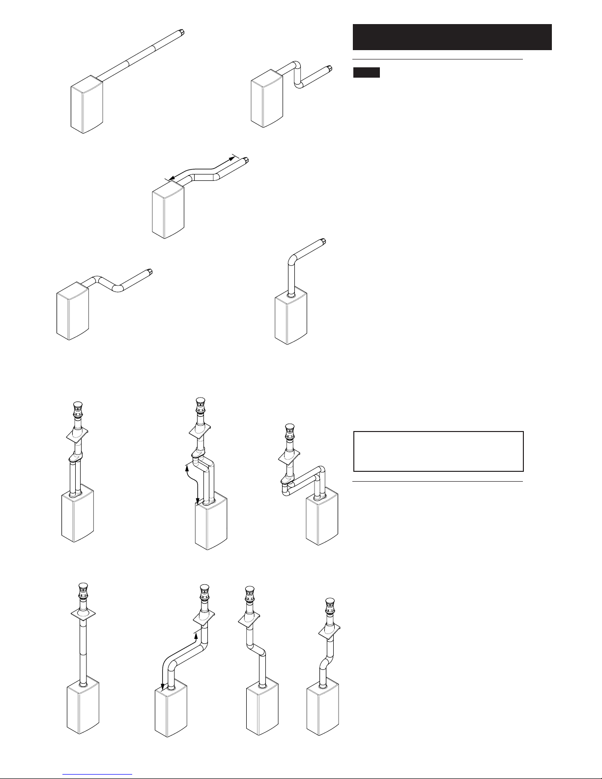
4.8 Flue Options
1. The Baxi Solo 3 PFL can be fitted with flue systems
as illustrated.
2, The standard flue is suitable only for horizontal
applications.
3. Maximum permissible equivalent flue lengths are:Horizontal 3.0 metres
Vertical 4.0 metres
Vertical (Twin) 20.0 metres
4. Any additional “in line” bends in the flue system
must be taken into consideration. Their equivalent
lengths are:-
Concentric Pipes:
45° bend 0.5 metres
90° bend 1.0 metres
Twin Flue Pipes
Air Duct Flue Duct
45° bend 1.3 metres 3.3 metres
90° bend 4.8 metres 12.0 metres
5. The illustrations opposite show examples of
maximum equivalent lengths.
6. Instructions for guidance and fitting are included in
each kit.
IMPORTANT: All flue systems must be securely
supported at least once every metre. Suitable pipe
supports are available as accessories.
Horizontal
Flues
Vertical
Flues
Vertical
Flues
(Twin Pipe)
Maximum Length = 2m inc. 2 x 45° bends
Maximum Length = 21m
inc. 4 x 45° bends
Maximum Length = 2m
inc. 2 x 90° bends
© Baxi Heating UK Ltd 2009
5.0 Installation
14
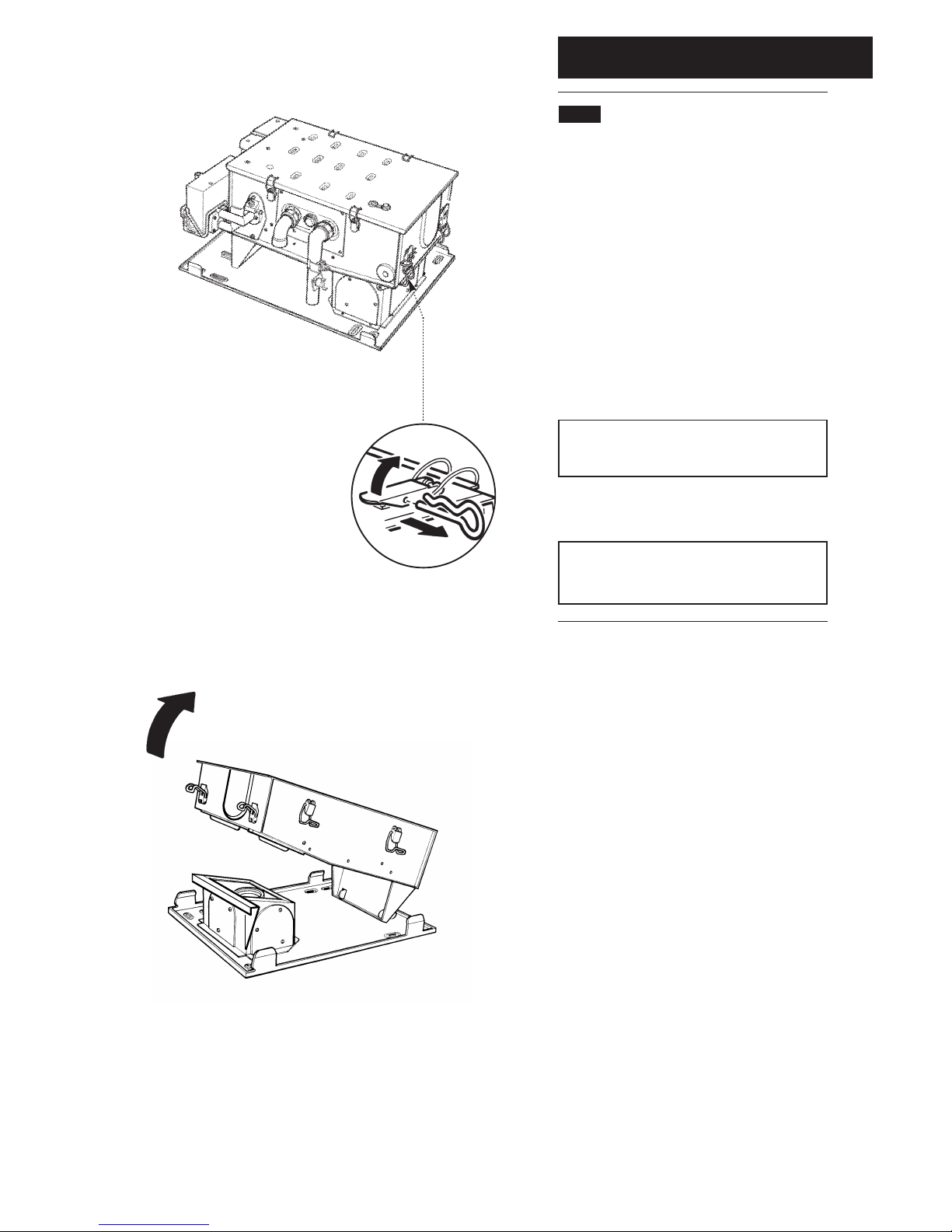
5.1 Initial Preparation
1. Unpack contents of carton.
2. Remove the lower door panel from the outer case.
Remove the 2 screws holding the outer case to the
combustion box.
3. Place the ready assembled outer case in a safe place
until required.
4. Release the R clip from the top latch securing the
combustion box to the back plate and release both
latches (Fig. 15).
5. Lift and remove the combustion box from the back
plate (Fig. 16). Place the combustion box on its back.
IMPORTANT - When installing a Solo 3 PFL with
a rear flue see section 5.2 before continuing the
installation.
6. Proceed to the relevant section for flueing the
appliance either to the Rear, Left, Right or Vertically.
NOTE: For Vertical flueing or flue lengths greater
than standard, the relevant optional extra kits must
be obtained and their instructions followed.
Fig. 15
Fig. 16
© Baxi Heating UK Ltd 2009
5.0 Installation
15
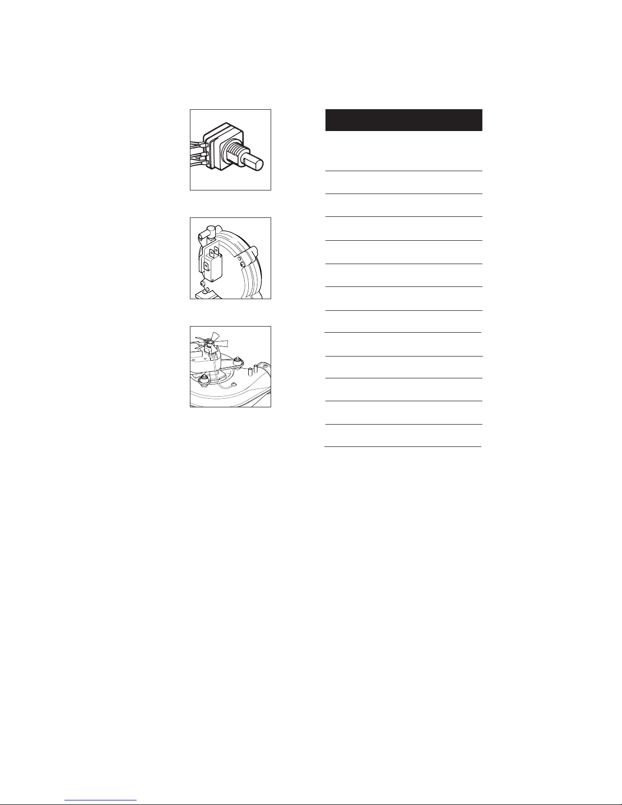
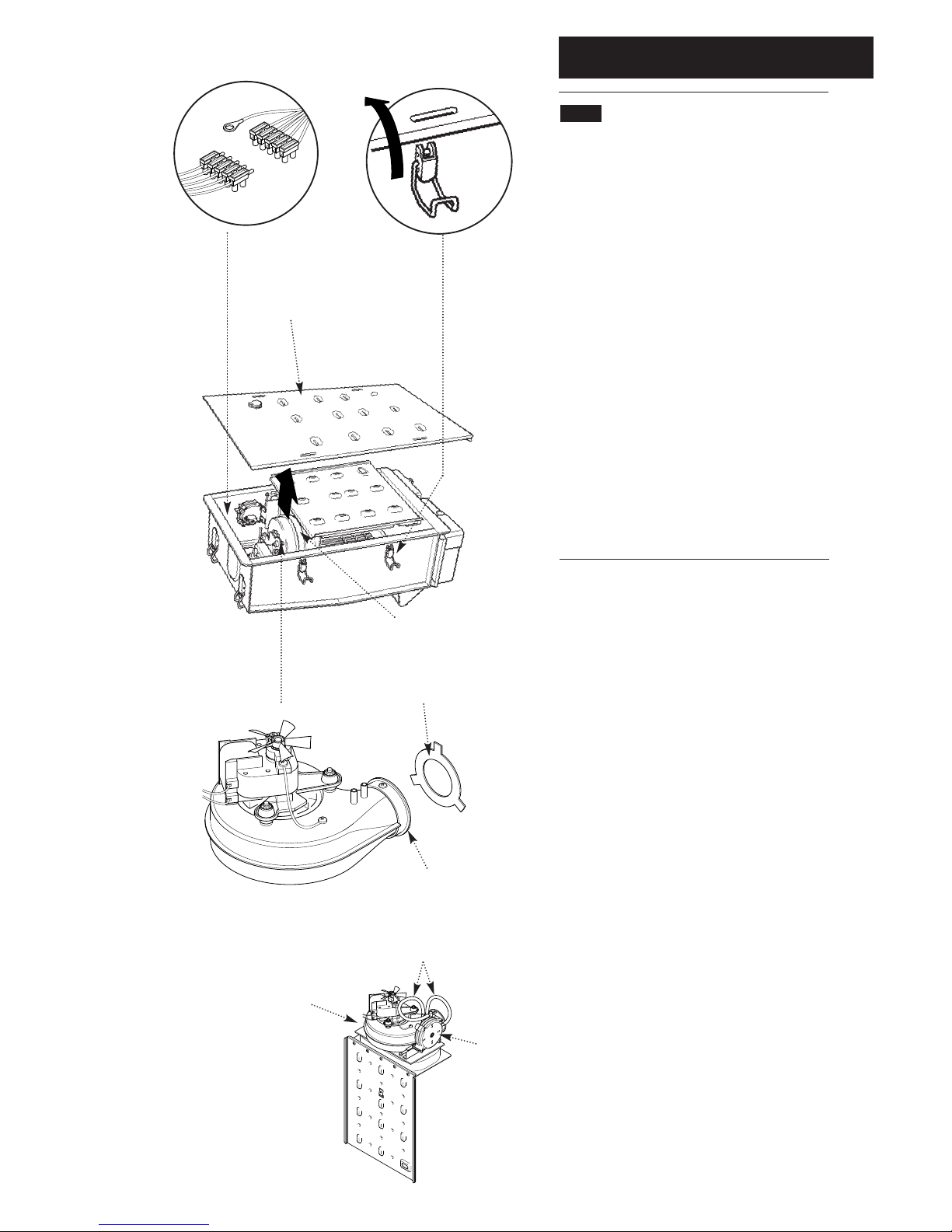
5.2 Fan Outlet Restrictor
Rear Flue only up to 500mm (195/8in)
1. Release the four latches holding the combustion box
door (Fig 18). Remove the combustion box door by
pulling forward (Fig. 17).
2. Release the 5-pin electrical plug connecting the
pressure switch and fan (Fig. 19). Withdraw the fan
assembly by pulling forwards from the top edge (Fig. 17).
3. Take the sheetmetal restrictor (supplied in the kit of
parts), check that the number stamped on the restrictor
matches the appliance (e.g. 50 stamped on the restrictor
is for PFL 50 appliance).
4. Fit the restrictor to the fan outlet flange, bending the 3
lugs equally ensuring the restrictor seals against the fan
outlet flange (Fig. 20).
5. Re-assemble the fan assembly and combustion box
door ensuring that the flexible tubes from the fan unit to
the pressure switch are routed correctly and that they
are not kinked or flattened (Fig. 21).
Fan Outlet Flange
Fan Outlet Restrictor
Fig. 19
Fig. 18
Fig. 17
Fig. 20
Flexible Tubes
Fig. 21
Combustion Box Door
Fan Assembly
Fan Assembly
Pressure
Switch
 Loading...