

Baxi Solo 3 30 PF System, Solo 3 40 PF System, Solo 3 60 PF System, Solo 3 50 PF System, Solo 3 70 PF System Installation And Servicing Instructions
...
Please leave these instructions with the user
Baxi Solo 3PF System
Wall Mounted Powered Flue System Boiler
Gas Fired Central Heating Unit
Comp No 245443 - Issue 1 - 9/99
Installation and
Servicing Instructions

Page 2
Natural Gas
Baxi Solo 3 30 PF System
G.C.No. 41 075 12
Baxi Solo 3 40 PF System
G.C.No. 41 075 13
Baxi Solo 3 50 PF System
G.C.No. 41 075 14
Baxi Solo 3 60 PF System
G.C.No 41 075 15
Baxi Solo 3 70 PF System
G.C.No. 41 075 16
Baxi Solo 3 80 PF System
G.C.No 41 075 17
Baxi Heating Ltd is one of the leading manufacturers of
domestic heating products in the UK.
Our first priority is to give a high quality service to our
customers. Quality is built into every Baxi product -products
which fulfil the demands and needs of customers, offering
choice, efficiency and reliability.
To keep ahead of changing trends, we have made a
commitment to develop new ideas using the latest
technology - with the aim of continuing to make the products
that customers want to buy.
The boiler meets requirements of Statutory Instrument “The
Boiler (Efficiency) Regulations 1993 No 3083” and is deemed
to meet the requirements of Directive 92/42/EEC on the
efficiency requirements for new hot water boilers fired with
liquid or gaseous fuels:-
Baxi is also the largest manufacturing partnership in the
country. Everyone who works at the company has a
commitment to quality because, as shareholders, we know
that satisfied customers mean continued success.
We hope you get a satisfactory service from Baxi. If not,
please let us know.
Baxi is a BS-EN ISO 9001
Accredited Company
Type test for purpose of Regulation 5 certified by:
Notified Body 0086.
Product/Production certified by:
Notified Body 0086.
For use in GB / IE only.
Contents - Page 3
Page4668111432343536
Section
1.0
2.0
3.0
4.0
5.0
6.0
7.0
8.0
9.0
10.0
11.0
12.0
13.0
Introduction
General Layout
Technical Data
System Details
Site Requirement
Installation
Commissioning the Appliance
Fitting the Outercase
Overheat Cut-Off Device
Annual Servicing
Changing Components
Short Parts List
Fault Finding
38
43
44
1.0 Introduction - Page 4
B.S. Codes of Practice
1.1 Description
1. The Baxi Solo 3 PF System is a gas fired room sealed
fan assisted central heating system boiler with range rated
outputs as shown in the table below.
2. Each appliance is preset at a MID RANGE heat input
rating and is designed for use on NATURAL GAS only.
3. All boilers are suitable for sealed fully pumped systems
only.
4. The appliance incorporates a circulating pump and
expansion vessel.
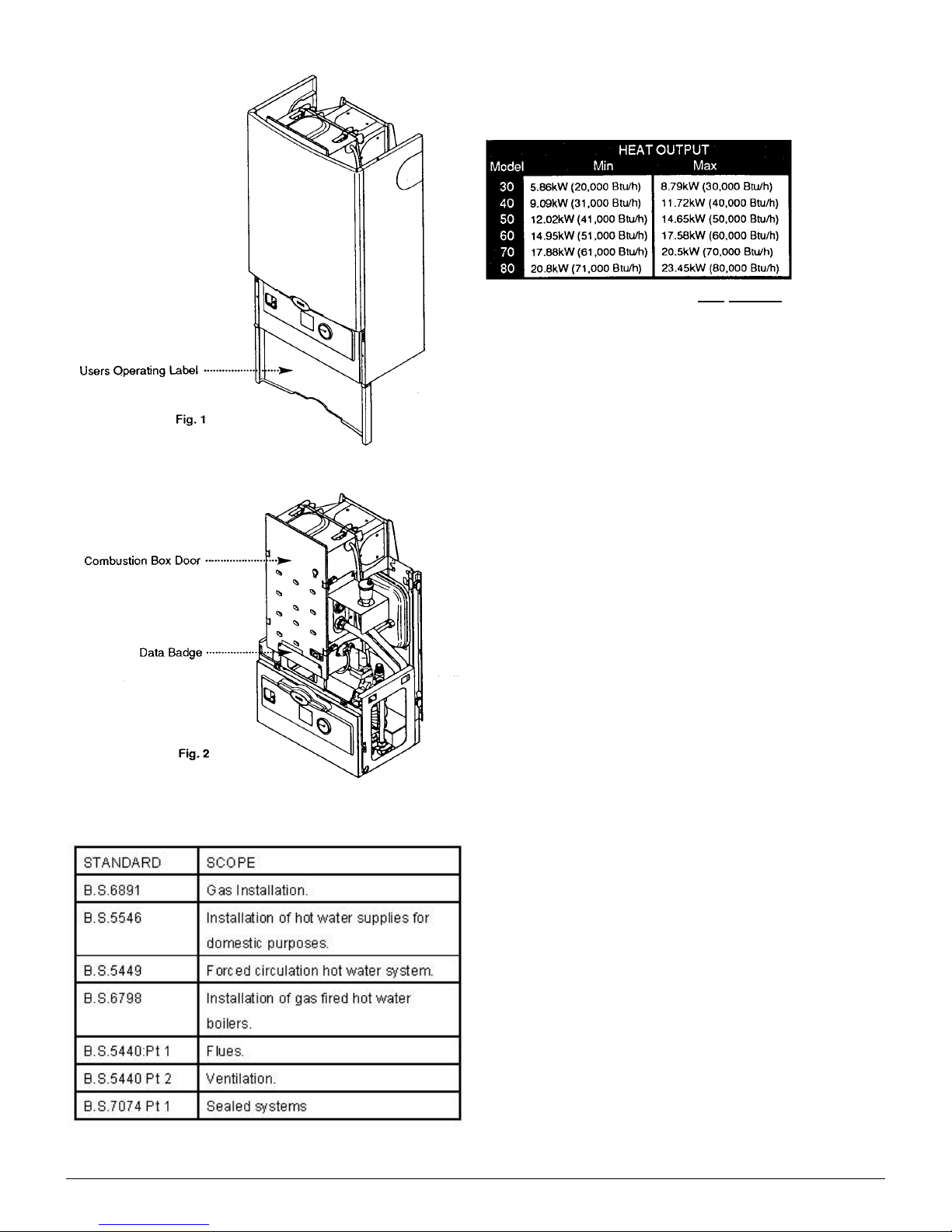
5. The appliance data badge is fitted to the combustion box
door, an abbreviated version is on the inside of the front
panel.
6. All illustrations show the Solo 50 3 PF System boiler.
1.2 Installation
1. The appliance is suitable for installation only in G.B. and
I.E. and should be installed in accordance with the rules in
force. For Ireland install in accordance with I.S.813
“INSTALLATION OF GAS APPLIANCES”. The installation must be
carried out by a CORGI Registered Installer or other
competent person and be in accordance with the relevant
requirements of the current GAS SAFETY (Installation and
Use) REGULATIONS, the BUILDING REGULATIONS (Scotland)
(Consolidation), the LOCAL BUILDING REGULATIONS, the
CURRENT I.E.E. WIRING REGULATIONS and the bye laws of the
Local Water Undertaking. Where no specific instructions are
given, reference should be made to the relevant BRITISH
STANDARD CODES OF PRACTICE.
2. All systems must be thoroughly flushed and treated
with inhibitor (see Section 4.2).
1.3 Important Information
COSHH Regulations
This product contains Refractory Ceramic Fibres (R.C.F.)
which are man-made vitreous silicate fibres. Excessive
exposure to these materials may cause temporary irritation
to eyes, skin and respiratory tract. Care must be taken when
handling these articles to ensure the release of dust or fibres
is kept to a minimum.
To ensure that the release of fibres from these articles is
kept to a minimum, during installation and servicing it is
recommended that a H.E.P.A. filtered vacuum is used to
remove any dust, soot or other debris accumulated in and
around the appliance. This should be performed before and
after working on the installation.
It is recommended that any replaced item(s) are not broken
up but sealed within heavy duty polythene bags and clearly
labelled “R.C.F. waste”. This is not classified as “hazardous
waste” and may be disposed of at a tipping site licensed for
the disposal of industrial waste. Protective clothing is not
required when handling these articles but it is recommended
that gloves are worn and the normal hygiene rules of not
smoking, eating or drinking in the work area are followed and
always wash hands before eating or drinking.
2.0 General Layout - Page 5
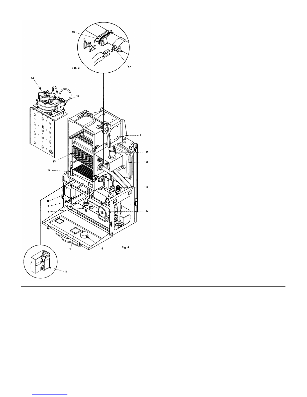
2.1 Layout (Figs. 3 & 4)
1. Wall Plate
2. Automatic Air Vent
3. Expansion Vessel
4. Pressure Relief Valve
5. Circulation Pump
6 Water Pressure Gauge
7. Position of Optional Timer
8. Gas Tap
9. Control Knob
10. Electronics Housing
11. Gas Valve
12. Burner
13. Heat Exchanger
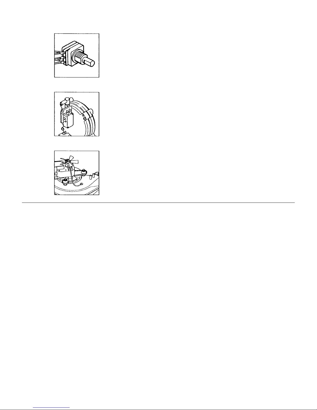
14. Fan Assembly
15. Pressure Switch
16. Overheat Thermostat
17. Thermostat Sensor
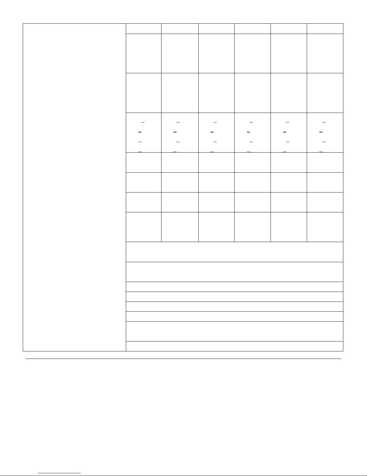
3.0 Technical Data - Page 6
Model 30 40 50 60 70 80
Heat Output (Max) kW 8.9 11.72 14.65 17.58 20.5 23.45
Btu/h 30,000 40,000 50,000 60,000 70,000 80,000
Heat Output (Min) kW 5.86 9.09 12.02 14.95 17.88 20.8
Btu/h 20,000 31,000 41,000 51,000 61,000 71,000
Heat Input (Max) kW 10.99 14.65 18.32 21.98 25.64 29.31
Btu/h 37,500 50,000 62,500 75,000 87,500 100,000
Heat Input (Min) kW 7.33 11.36 15.02 18.68 22.35 26.01
Btu/h 25,000 38,750 51,250 63,750 76,250 88,750
Burner Pressure (Max) mbar 16.0 + 0.5 16.0 + 0.5 16.0 + 0.5 16.0 + 0.5 16.0 + 0.5 16.0 + 0.5
in wg 6.4 + 0.2 6.4 + 0.2 6.4 + 0.2 6.4 + 0.2 6.4 + 0.2 6.4 + 0.2
Burner Pressure (Min) mbar 8.0 + 0.5 10.0 + 0.5 11.5 + 0.5 11.5 + 0.5 12.1 + 0.5 11.5 + 0.5
in wg 3.2 + 0.2 4.0 + 0.2 4.4 + 0.2 4.4 + 0.2 4.8 + 0.2 4.4 + 0.2
Gas Rate CV38MJm
(after 10 mins) 36.86ft3/h 49.0ft3/h 61.3ft3/h 73.5ft3/h 86.75ft3/h 98.1ft3/h
Lifting Weight kg 40 40 40 49.1 49.1 49.1
Water Content litres 2.1 2.1 2.1 2.6 2.6 2.6
3
1.04m 3/h 1.39m 3/h 1.74m 3/h 2.08m 3/h 2.43m 3/h 2.78m 3/h
lbs 88 88 88 108 108 108
pints 3.2 3.2 3.2 4.5 4.5 4.5
Outercase Height 850mm 850mm 850mm 850mm 850mm 850mm
Dimensions Width 490mm 490mm 490mm 490mm 490mm 490mm
Depth 320mm 320mm 320mm 320mm 320mm 320mm
Flue Terminal Diameter 100mm
Dimensions Depth 70mm
Connections Flow 22mm Cu tail
Return 22mm Cu tail
Heat Exchanger Cast iron monobloc
System Design fully pumped sealed systems only
Gas Connection 22m Cu tail
Electrical Supply 230V ~ 50 Hz fused 5A - 90W
Controls boiler thermostat, intermittent pilot & electronic flame sensing,
timed pump over-run, frost protection thermostat
Internal Fuse 4AF 250V to BS4256 situated on control board
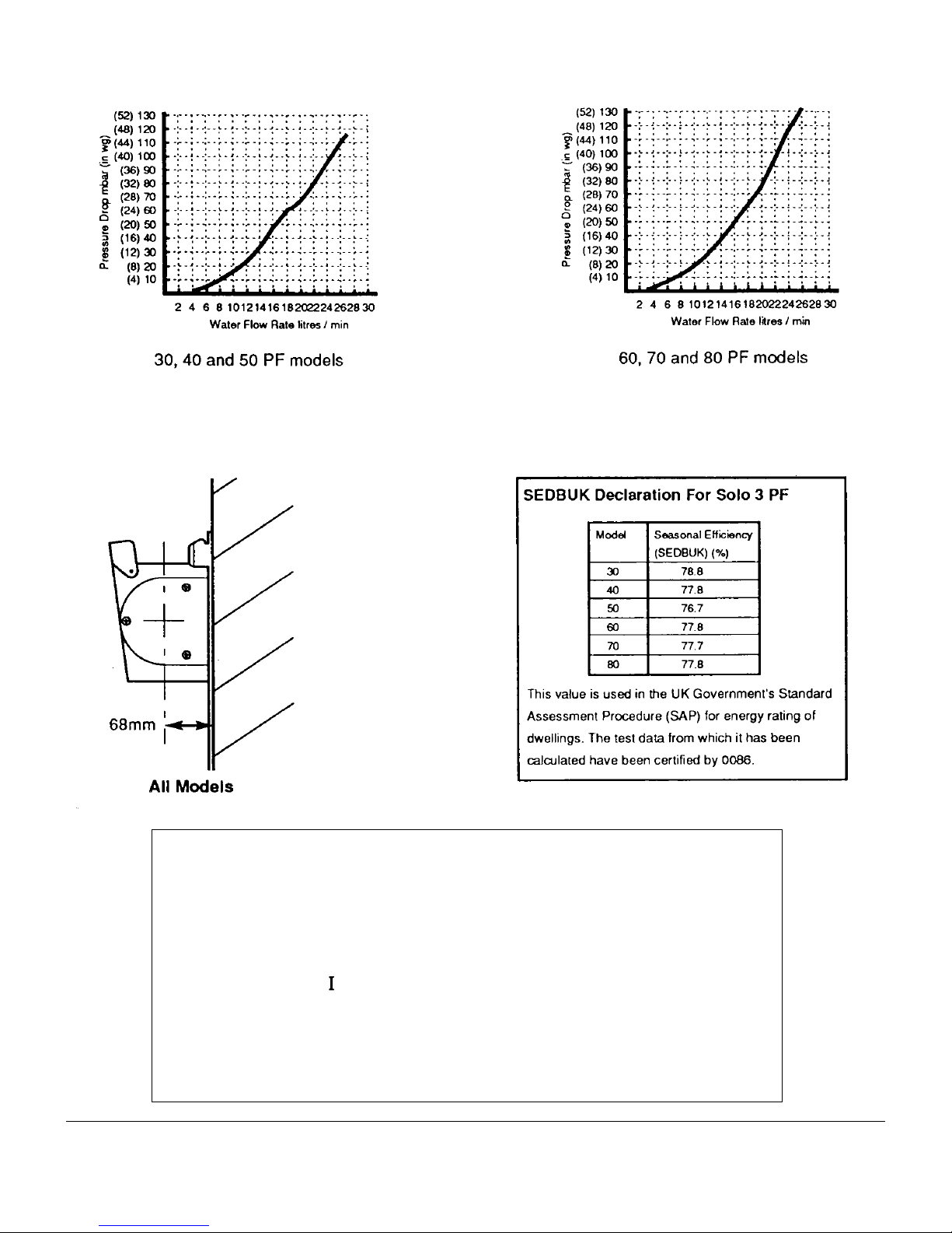
3.0 Technical Data - Page 7
Hydraulic Resistance Charts
• This appliance is only intended for installation on a governed supply.
• PMS = 3 bar pressure class 2
• Max CH water pressure 3 bar
• Type C12 C
32
• Nox class 2
• Appliance category
• Ret: 86/AU/588
• Burner Injector Sizes: 30=B31 40=B32 50=B33 60=B34 70=B35 80=B36
• This boiler is designed to operate at a maximum water temperature of 85º C.
2H - G20 - 20mbar
2H
4.0 System Details - Page 8
4.1 Water Circulating Systems
Water Circulating Systems
1. The appliance is suitable for fully pumped sealed systems
only.
The following conditions should be observed on all
systems:
• The boiler must not be used with a direct cylinder.
• Drain cocks should be fitted to all system low points.
• All gas and water pipes and electrical wiring must be
installed in a way which would not restrict the servicing of the
boiler.
• Air vents should be fitted to all system high points.
• All components used in the system must be suitable for
operation at 110ºC (230ºF).
4.2 Treatment of Water Circulating Systems
• All recirculatory water systems will be subject to
corrosion unless an appropriate water treatment is applied.
This means that the efficiency of the system will deteriorate
as corrosion sludge accumulates within the system, risking
damage to pump and valves, boiler noise and circulation
problems.
• For optimum performance after installation this boiler
and its associated central heating system must be flushed in
accordance with the guidelines given in BS 7593:1992
“Treatment of water in domestic hot water central heating
systems”.
• This must involve the use of a proprietary cleanser, such
as BetzDearborn Sentinel X300 or X400, or Fernox
Superfloc. Full instructions are supplied with the products,
but for immediate information please contact BetzDearborn
(0151 420 9563) or Fernox (01799 550 811) directly.
• For long term protection against corrosion and scale,
after flushing it is recommended that an inhibitor such as
BetzDearbom Sentinel X100, or Femox MB-1 or Copal is
dosed in accordance with the guidelines given in BS
7593:1992.
Failure to flush and add inhibitor to the system may
invalidate the appliance warranty.
• It is important to check the inhibitor concentration after
installation, system modification and at every service in
accordance with the manufacturers instructions. (Test kits
are available from inhibitor stockists.)
• For information or advice regarding any of the above
contact the Baxi Helpline.
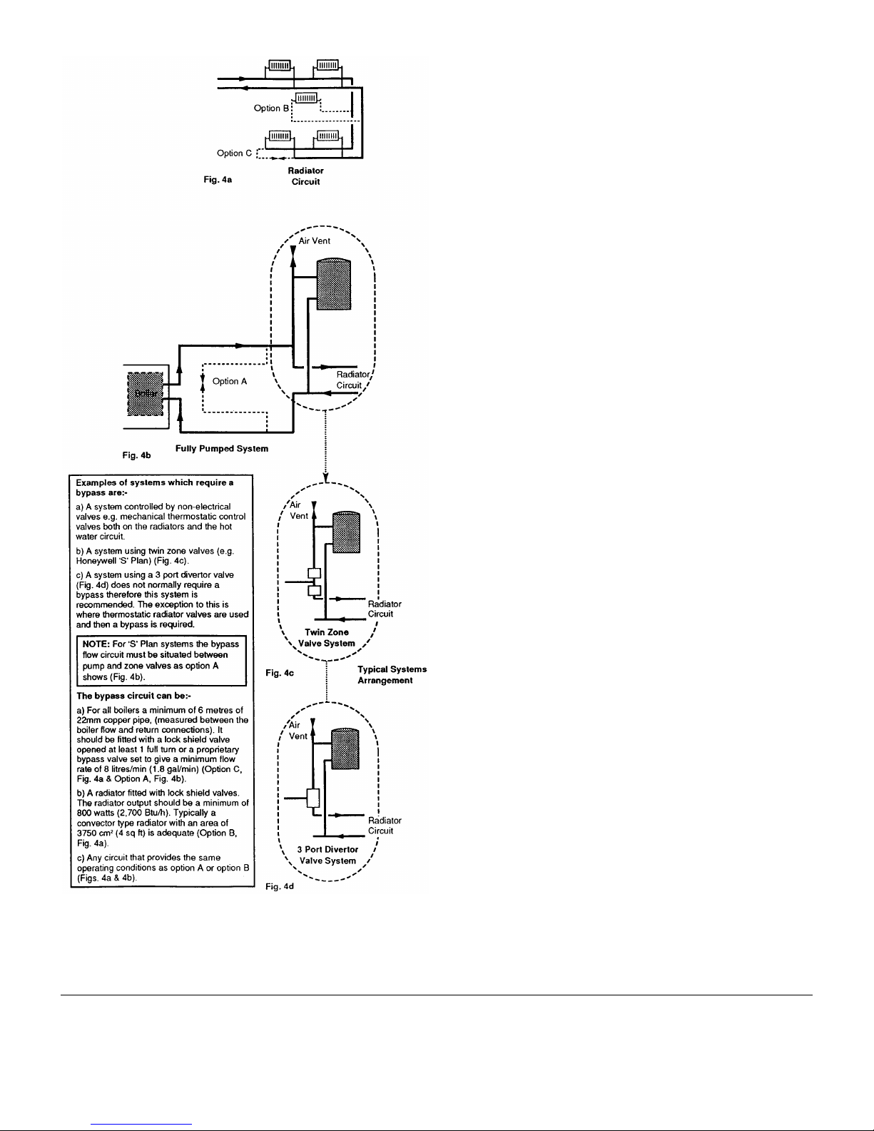
4.3 Bypass Requirements
1. The boiler is fitted with a pump overrun device which
allows the removal of residual heat from the boiler.
NOTE: The pump overrun will operate for approximately
8 minutes. The system design must therefore always
provide an open circuit for water to circulate between
the boiler flow and return.

4.0 System Details - Page 9
4.4 Pipework
1. The sizes of flow and return pipes from the boiler should
be determined by normal methods, according to the
requirements of the system.
2. The connections to the boiler are 22mm copper tails.
4.5 System Controls
1. For optimum operating conditions, the heating system
into which the boiler is installed should include a control
system.
2. Such a system will comprise of a timer control and
separate room or cylinder thermostats as appropriate. (An
integral twin channel programmer is available as an optional
extra).
3. The boiler should be controlled so that it operates on
demand only.
4. Operation of the system under control of the boiler
thermostat & TRV’s only does not produce the best results
4.6 Thermal Stores & Heat Stores
1. If a thermal store or heat store is being used, it should be
one approved for use with the Baxi Solo 3 PF System Boiler.
4.0 System Details - Page 10
4.7 System Filling and Pressurising
1. A filling point connection on the central heating return
pipework must be provided to facilitate initial filling and
pressurising and also any subsequent water loss
replacement/refilling.
2. The filling method adopted must be in accordance with all
relevant water supply bye-laws and use approved
equipment.
3. Your attention is drawn to: RN 302 and Byelaw
14.
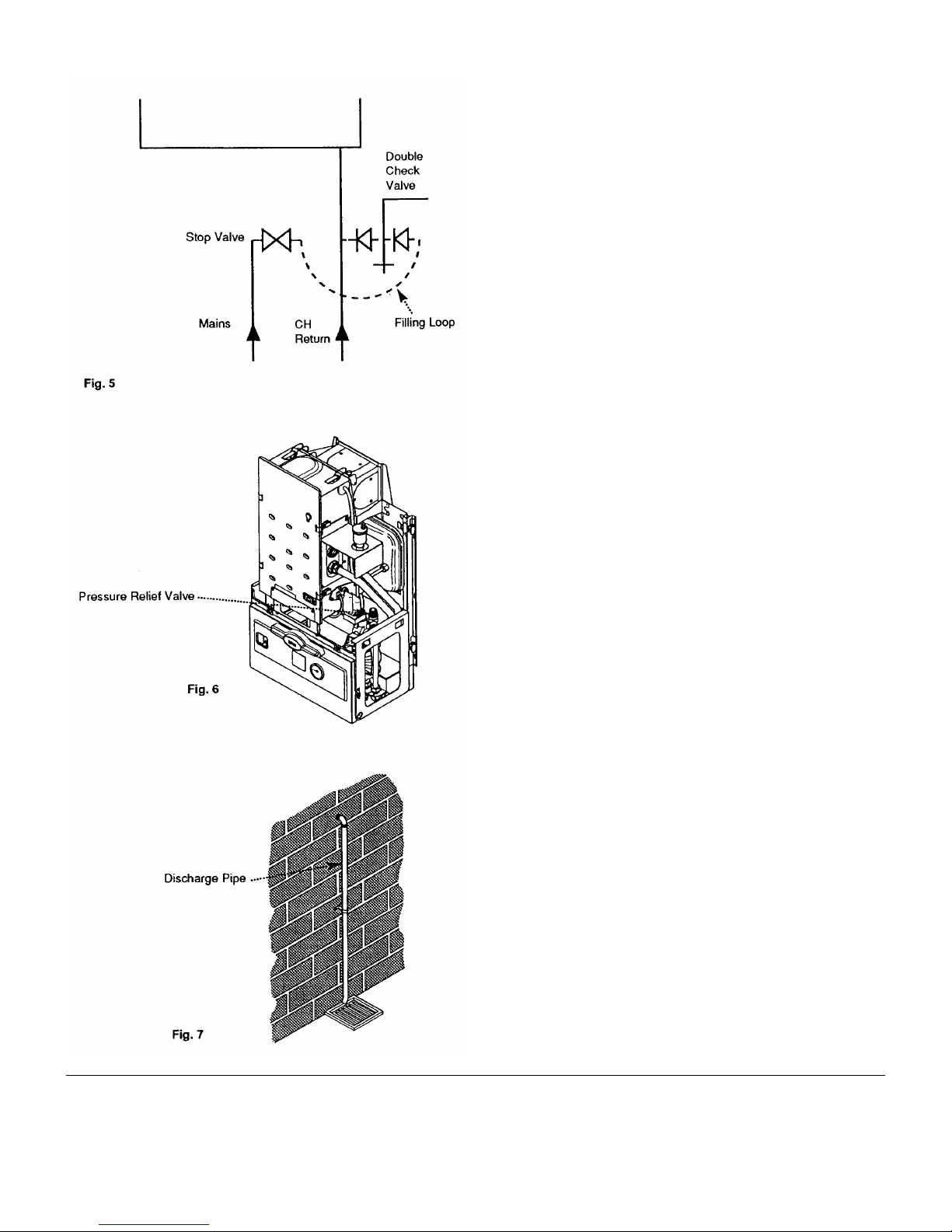
4. The sealed primary circuits may be filled or replenished
by means of a temporary connection (Filling Loop) between
the circuit and a supply pipe, provided a WRC approved
double check valve or some other no less effective backflow
prevention device is permanently connected at the inlet to
the circuit and the temporary connection (Filling Loop) is
removed after use (Fig. 5).
4.8 Expansion Vessel
1. The appliance expansion vessel is pre-charged to 1 bar
(10 lb/in2). Therefore, the minimum cold fill pressure is 1 bar.
The vessel is suitable for correct operation for system
capacities up to 125 litres (27.5gal). For greater system
capacities an additional expansion vessel must be fitted refer to BS 7074 Pt 1.
4.9 Pressure Relief Valve (Figs. 6 & 7)
1. The pressure relief valve is set at 3 bar, therefore all
pipework, fittings, etc. should be suitable for pressures in
excess of 3 bar.
2. The pressure relief discharge pipe should be not less
than 15mm dia, run continuously downward, and discharge
outside the building, preferably over a drain. It should be
routed in such a manner that no hazard occurs to occupants
or causes damage to wiring or electrical components. The
end of the pipe should terminate facing down and towards
the wall.
3. The discharge must not be above a window, entrance or
other public access. Consideration must be given to the
possibility that under fault conditions boiling water/steam
could discharge from the pipe.
4. The pressure relief valve must not be used for draining
the system/boiler.
5.0 Site Requirements - Page 11
5.1 Location
1. The appliance may be fitted to any suitable wall with the
flue passing through an outside wall and discharging to
atmosphere in a position permitting satisfactory removal of
combustion products and providing an adequate air supply.
The appliance should be fitted within the building unless
otherwise protected by a suitable enclosure ie. garage or
outhouse. (The appliance may be fitted inside a cupboard.
Cooling ventilation and insulation of the cupboard are not
required, see section 5.5.)
2. If the appliance is fitted in a room containing a bath or
shower reference must be made to the Current l.E.E. Wiring
Regulations and Building Regulations. If the appliance is to
be fitted into a building of timber frame construction then
reference must be made to the Institute of Gas Engineers
document UP7 (“Guide for Gas Installation in Timber
Framed Dwellings”).
3. Recommendations for flues are given in BS 5440 Part 1.
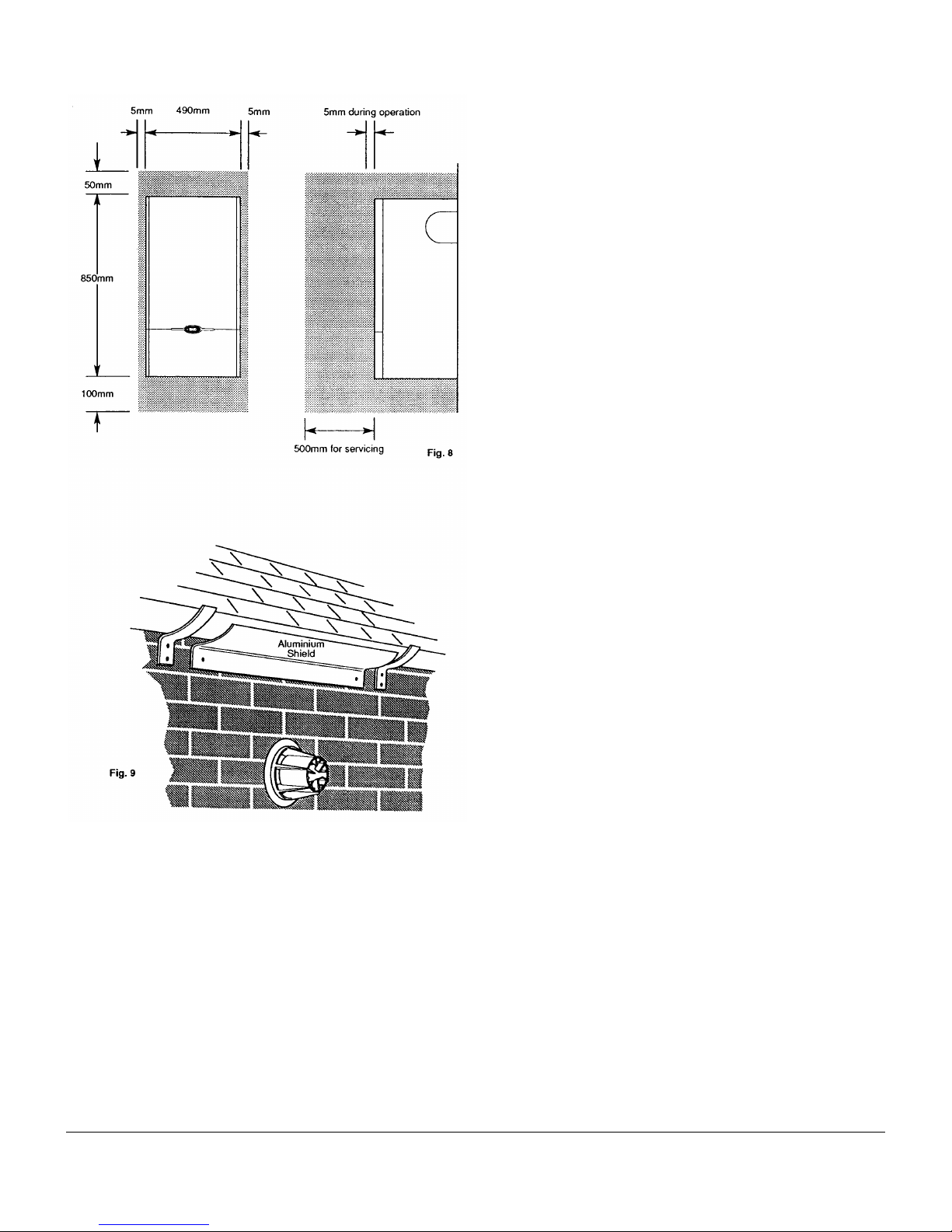
5.2 Minimum Clearances (Fig. 8)
1. A flat vertical area is required for the installation of the
boiler.
2. These dimensions include the necessary clearances
around the appliance for case removal, spanner access and
air movement. Additional clearances may be required for the
passage of pipes around local obstructions such as joists
running parallel to the front face of the appliance.
3. If fitted inside a cupboard the clearance of 500mm shown
is only necessary when the cupboard door is open. A
clearance of 5mm (3/16 in) is required when the door is
closed.
5.3 Flue Position
1. For installations where the flue terminal is inaccessible
from the outside, an internal fitting kit is available. This can
be obtained free of charge from your local merchant.
2. The following guide lines indicate the general
requirements for siting balanced flue terminals.
3. If the terminal is fitted within 1 metre (39in) of a plastic
gutter, within 500mm (19½ in) of a painted eave or a painted
gutter, an aluminium shield of at least 1 metre (39in) long
should be fitted to the underside of the gutter or painted
surface. An air space of 5mm (3/16 in) should be left between
shield and gutter (Fig. 9).
4. If the terminal discharges onto a pathway or passageway,
check that combustion products will not cause a nuisance
and that the terminal will not obstruct the passageway.
5. If the outer surface of an outside wall is of combustible
material, it should be protected by fitting the flue film
provided.
5.0 Site Requirements - Page 12
5.3 Flue Position (Cont)
WARNING - The addition of anything that may interfere
with the normal operation of the appliance (e.g. FLUE
DAMPERS, ECONOMISERS,etc.) without the express
written permission of Baxi Heating Ltd could invalidate
the appliance warranty and Infringe the GAS SAFETY
(Installation and Use) REGULATIONS.
If a terminal is less than 2 metres (78¾ in) above a
balcony, above ground or above a flat roof to which
people have access then a suitable terminal guard must
be provided.
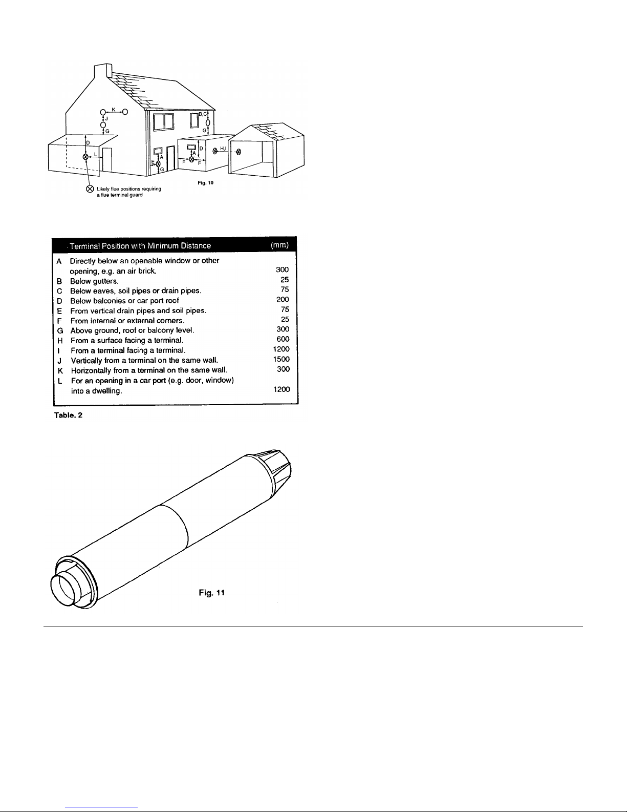
6. Table 2 and Fig. 10 show the positioning of the flue
terminal relative to buildings and other structures.
7. The dimensions of the flue terminal are shown on page 6.
5.4 Flue Dimensions
1. Flue extensions are available as optional extras for
installations up to 3 metres (1181/8 in) horizontal.
2. Vertical flue kits are available up to 4 metres in
length. Vertical twin flue kits are available up to 15
metres In length.
3. The standard flue supplied with the appliance is suitable
for use with flue lengths between 100mm (4in) and 500mm
(195/8 in).
NOTE: Maximum flue length when flued to the left or
right is
350mm - Left Hand Flue
330mm - Right Hand Flue
4. Where it is intended to pass the flue through a
combustible wall or timber framed dwelling, reference should
be made to the Institute of Gas Engineers document UP7 Guide for Gas Installations in Timber Framed Dwellings.
5. If the flue is more than 1 metre (393/8 in) long, it is
required that it is supported.
6. All above dimensions are taken from the respective
faces of the outer case.
5.0 Site Requirements - Page 13
5.5 Ventilation of Compartments
1. Where the appliance is installed in a cupboard or
compartment, no air vents are required.
NOTE: The ventilation label on the front of the outer
case MUST NOT BE REMOVED when the appliance is
installed in a compartment or cupboard.
2. B.S. 5440 Part 2 Clause 4.2 refers to room sealed
appliances installed in compartments. This appliance will run
sufficiently cool without ventilation.
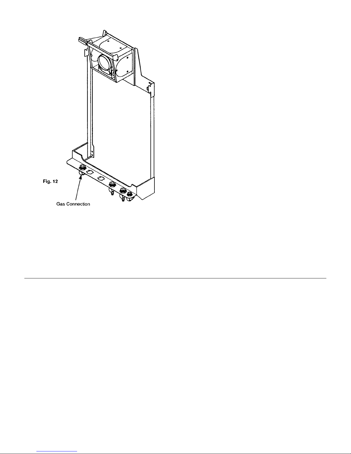
5.6 Gas Supply
1. The gas installation should be in accordance with BS
6891.
2. The connection of the appliance is a 22mm copper tail on
the tap rail (Fig. 12).
3. The pipework should be sized to account for the distance
of the appliance from the meter, the pipe routing and
maximum input of the appliance.
5.7 Electrical Supply
External wiring must be correctly earthed, polarized and in
accordance with CURRENT I.E.E. WIRING REGULATIONS.
The mains supply is 230V ~ 50Hz fused at 5A.
NOTE: The method of connection to the electricity
supply must facilitate complete electrical isolation of the
appliance.
Connection may be made via a fused double-pole isolator
with a contact separation of a least 3mm in all poles and
serving the appliance and system controls only.

6.0 Installation - Page 14
6.1 Initial Preparation
1. Remove the hinged lower door panel from the outer case
by opening it to 90º and pulling forwards (Fig. 13).
2. Remove the 2 screws holding the outer case to the
combustion box (Fig. 13).
3. Place the outer case in a safe place until required.
4. Remove the R clip from the latch securing the
combustion box to the back plate and release the latches
(Fig. 14a & 14b).
5. Lift and remove the combustion box and backplate from
the wall plate (Fig. 14). Place the combustion box and
backplate on its back.
IMPORTANT - When installing a Solo 3 System with a
rear flue see section 6.2 Fan Outlet Restrictor before
continuing the installation.
6. Proceed to the relevant section for flueing the appliance
either to the Rear, Left, Right or Vertically.
NOTE: For Vertical flueing or flue lengths greater than
standard, the relevant optional extra kits must be
obtained and their instructions followed.
 Loading...