

Baxi Solo 3 Installation And Servicing Instructions
Supplied By www.heating spares.co Tel. 0161 620 6677
Baxi Solo 3 PFL System
Wall Mounted Powered Flue System Boiler
Gas Fired Central Heating Unit
Installation and
Servicing Instructions
Please leave these instructions with the user

Supplied By www.heating spares.co Tel. 0161 620 6677
2
Baxi UK Limited is one of the leading manufacturers
of domestic heating products in the UK.
Our first priority is to give a high quality service to our
customers. Quality is built into every Baxi product products which fulfil the demands and needs of
customers, offering choice, efficiency and reliability.
To keep ahead of changing trends, we have made a
commitment to develop new ideas using the
latest technology - with the aim of continuing to
make the products that customers want to buy.
Everyone who works at Baxi has a commitment to
quality because we know that satisfied customers
mean continued success.
We hope you get a satisfactory service from Baxi. If
not, please let us know.
Natural Gas
Baxi Solo 3 PFL System 30
G.C.No. 41 075 25
Baxi Solo 3 PFL System 40
G.C.No. 41 075 26
Baxi Solo 3 PFL System 50
G.C.No. 41 075 27
Baxi Solo 3 PFL System 60
G.C.No. 41 075 28
Baxi Solo 3 PFL System 70
G.C.No. 41 075 29
Baxi Solo 3 PFL System 80
G.C.No. 41 075 31
Baxi is a BS-EN ISO 9001
Accredited Company
The boiler meets the requirements of Statutory Instrument
“The Boiler (Efficiency) Regulations 1993 N
o
3083” and is
deemed to meet the requirements of Directive 92/42/EEC
on the energy efficiency requirements for new hot water
boilers fired with liquid or gaseous fuels:-
Type test for purpose of Regulation 5 certified by:
Notified Body 0086.
Product/Production certified by:
Notified Body 0086.
For use in GB/IE only
Supplied By www.heating spares.co Tel. 0161 620 6677
3
1.0 Introduction 4
2.0 General Layout 5
3.0 Technical Data 6
4.0 System Details 8
5.0 Site Requirement 11
6.0 Installation 14
7.0 Commissioning the Appliance 32
8.0 Fitting the Outercase 34
9.0 Overheat Cut-Off Device 35
10.0 Annual Servicing 36
11.0 Changing Components 38
12.0 Short Parts List 44
13.0 Fault Finding 45
Section Page
Contents

Supplied By www.heating spares.co Tel. 0161 620 6677
Model Heat Output
30
8.79kW (30,000 Btu/h)
40 11.72kW (40,000 Btu/h)
50 14.65kW (50,000 Btu/h)
60 17.58kW (60,000 Btu/h)
70 20.5kW (70,000 Btu/h)
80 23.44kW (80,000 Btu/h)
1.0 Introduction
4 1
1.1 Description
1. The Baxi Solo 3 PFL System is a gas fired room
sealed fan assisted central heating system boiler
with outputs as shown in the table below.
2. Each appliance is preset at a heat input rating
and is designed for use on NATURAL GAS only.
3. All boilers are suitable for sealed fully pumped
systems only.
4. The appliance incorporates a circulating pump
and expansion vessel.
5. The appliance data badge is fitted to the
combustion box door, an abbreviated version is on
the inside of the front panel.
6. All illustrations show the Solo 3 PFL System 50
boiler.
1.2 Installation
1. The appliance is suitable for installation only in
G.B. and I.E. and should be installed in
accordance with the rules in force. For Ireland
install in accordance with I.S.813 “I
NSTALLATION OF
GAS APPLIANCES”. The installation must be carried
out by a CORGI Registered Installer or other
competent person and be in accordance with the
relevant requirements of the current G
AS SAFETY
(Installation and Use) REGULATIONS, the BUILDING
REGULATIONS (Scotland) (Consolidation), the LOCAL
BUILDING REGULATIONS, the CURRENT I.E.E. WIRING
REGULATIONS and the bye laws of the Local Water
Undertaking. Where no specific instructions are
given, reference should be made to the relevant
BRITISH STANDARD CODES OF PRACTICE.
2. All systems must be thoroughly flushed and
treated with inhibitor (see Section 4.2).
1.3 Important Information
Man-Made Mineral Fibre
a) Some component parts of this appliance
(insulation pads, gaskets and rope seals) are
manufactured from man-made mineral fibre.
b) Prolonged or excessive exposure to this
material may result in some irritation to the eyes,
skin or respiratory tract.
c) It is advisable to wear gloves when handling
these items.
d) Irritant dust will only be released from the items
if they are broken up or subjected to severe
abrasion. In these instances a suitable dust mask
and goggles should be worn.
e) Always thoroughly wash hands after installation,
servicing or changing components.
f) When disposing of any items manufactured from
man-made mineral fibre care must be exercised.
g) If any irritation of the eyes or severe irritation of
the skin is experienced seek medical attention.
Users Operating Label
Data Badge
Combustion Box Door
Fig. 1
Fig. 2
“Benchmark” Log Book
As part of the industry-wide “Benchmark” intiative all Baxi boilers now
include an Installation, Commissioning and Service Record Log Book.
Please read the Log Book carefully and complete all sections relevant to
the appliance and installation. These include sections on the type of
controls employed, flushing the system, burner operating pressure etc.
The details of the Log Book will be required in the event of any warranty
work. Also, there is a section to be completed at each subsequent regular
service visit. The Log Book must be left with the user.
IMPORTANT:
STATEMENT OF ADJUSTMENT. Check that the state of adjustment
given on the data plate is compatible with local supply conditions
British Gas Service
Test Point.
For use by B.G.
Personnel only
Supplied By www.heating spares.co Tel. 0161 620 6677
2.0 General Layout
5
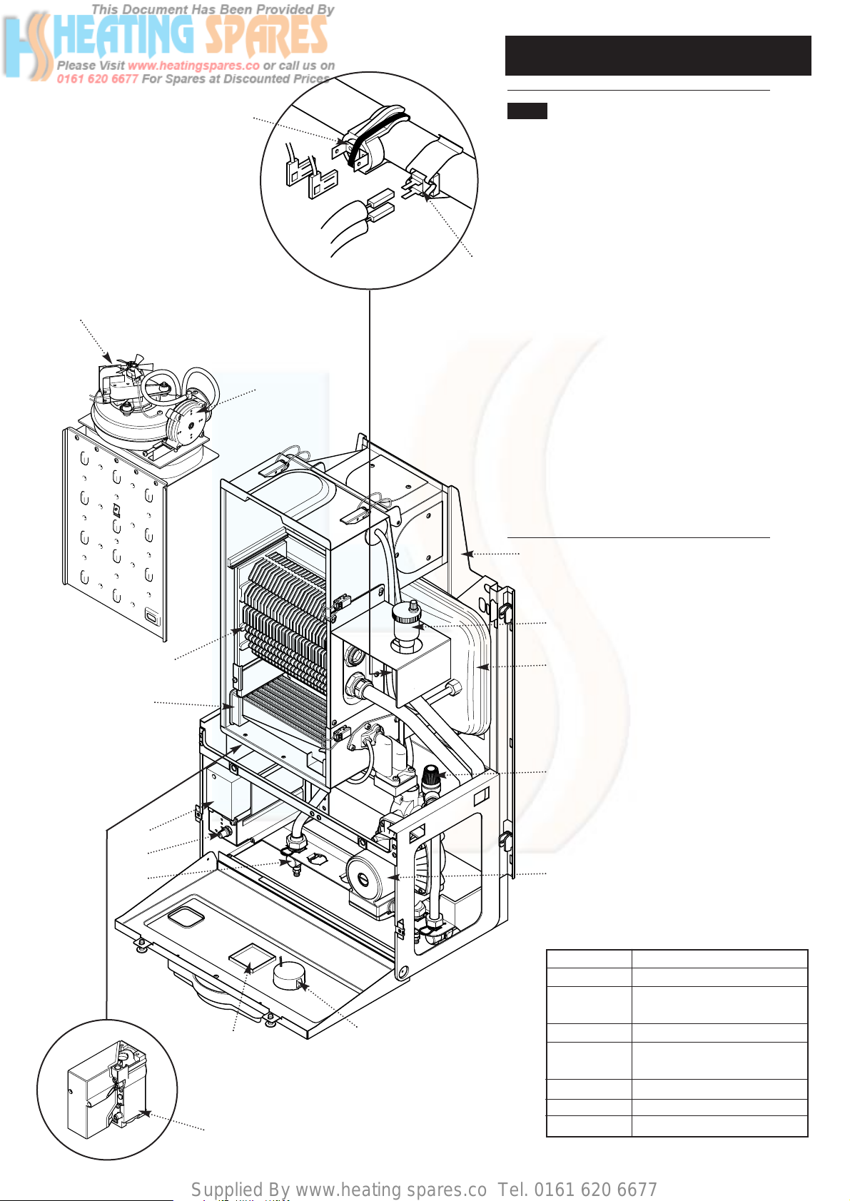
2.1 Layout (Figs. 3 & 4)
1. Wall Plate
2. Automatic Air Vent
3. Expansion Vessel
4. Pressure Relief Valve
5. Circulation Pump
6. Water Pressure Gauge
7. Position of Optional Timer
8. Gas Tap
9. Control Knob
10. Electronics Housing
11. Gas Valve
12. Burner
13. Heat Exchanger
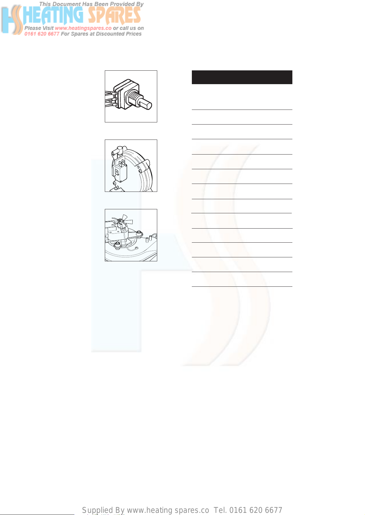
14. Fan Assembly
15. Pressure Switch
16. Overheat Thermostat
17. Thermostat Sensor
1
2
Fig. 4
Fig. 3
3
4
5
6
7
8
9
10
11
12
13
14
15
16
17
STANDARD
B.S. 6891
B.S. 5546
B.S. 5449
B.S. 6798
B.S. 5440: Pt 1
B.S. 5440: Pt 2
B.S. 7074: Pt 1
SCOPE
Gas Installation.
Installation of hot water supplies for
domestic purposes.
Forced circulation hot water systems.
Installation of gas fired hot water
boilers.
Flues.
Ventilation.
Sealed Systems
B.S. Codes of Practice, most recent
version should be used
Supplied By www.heating spares.co Tel. 0161 620 6677
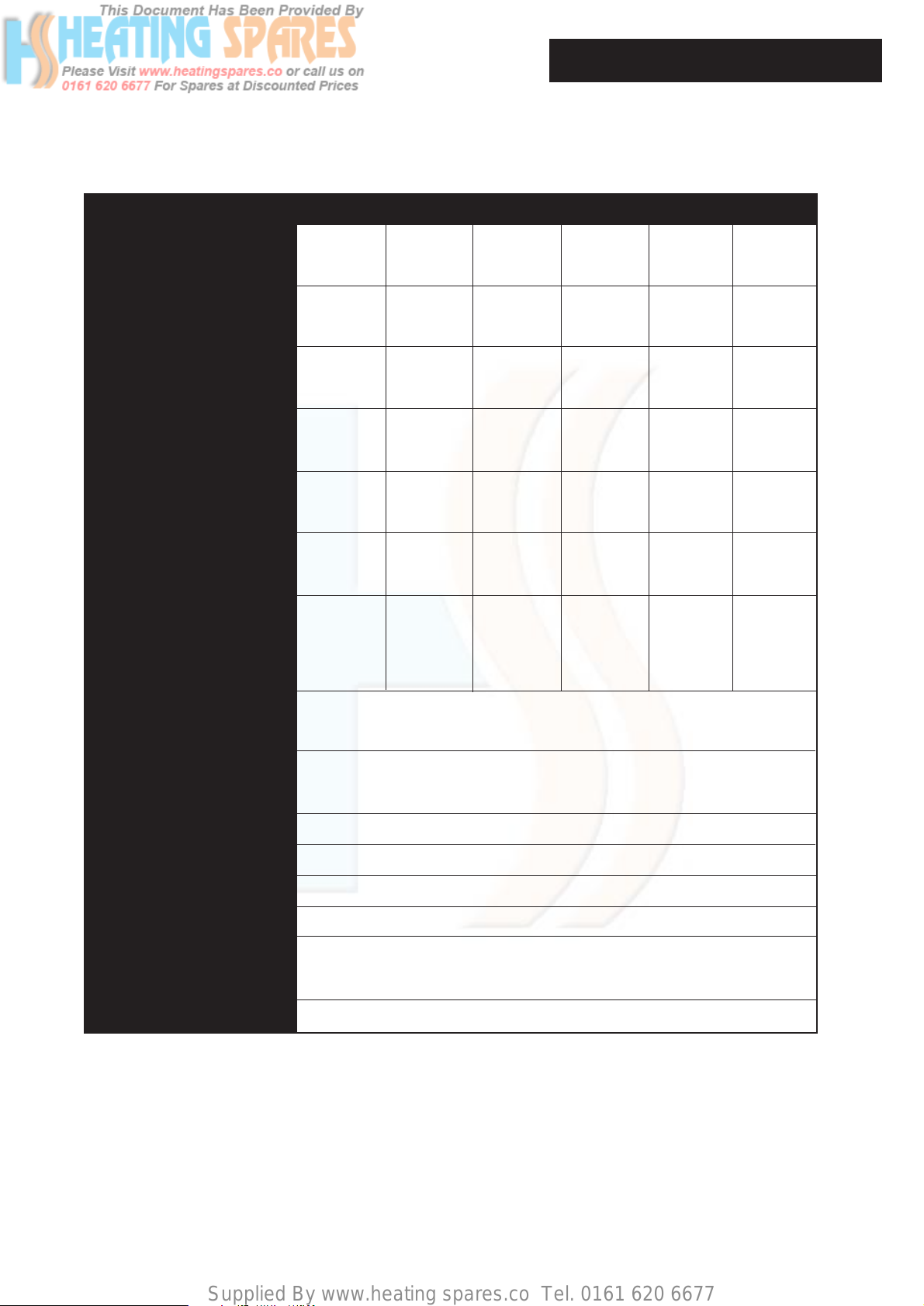
3.0 Technical Data
6
Model 30 40 50 60 70 80
Heat Output kW 8.79 11.72 14.65 17.58 20.5 23.44
Btu/h 30,000 40,000 50,000 60,000 70,000 80,00
Heat Input kW 10.99 14.65 18.32 21.98 25.64 29.31
Btu/h 37,500 50,000 62,500 75,000 87,500 100,000
Burner Pressure mbar 16.0 ±0.5 16.0 ±0.5 16.0 ±0.5 16.0 ±0.5 16.0 ±0.5 16.0 ±0.5
in wg 6.4 ±0.2 6.4 ±0.2 6.4 ±0.2 6.4 ±0.2 6.4 ±0.2 6.4 ±0.2
Gas Rate CV 38mj/m31.04m3/h 1.39m3/h 1.74m3/h 2.08m3/h 2.43m3/h 2.78m3/h
(after 10 mins) 36.86ft3/h 49.0ft3/h 61.3ft3/h 73.5ft3/h 86.75ft3/h 99.24ft3/h
Lifting Weight kg 40 40 40 49.1 49.1 49.1
lbs 88 88 88 108 108 108
Water Content litres 2.1 2.1 2.1 2.6 2.6 2.6
pints 3.2 3.2 3.2 4.5 4.5 4.5
Outercase Height 850mm 850mm 850mm 850mm 850mm 850mm
Dimensions Width 490mm 490mm 490mm 490mm 490mm 490mm
Depth 320mm 320mm 320mm 320mm 320mm 320mm
Flue Terminal Diameter 100mm
Dimensions Depth 70mm
Connections Flow 22mm Cu tail
Return 22mm Cu elbow
Heat Exchanger Cast iron monobloc
System Design fully pumped sealed systems only
Gas Connection 22mm Cu tail
Electrical Supply 230V ~ 50Hz fused 5A - 90W
Controls boiler thermostat, intermittent pilot & electronic flame sensing
timed pump over-run, frost protection thermostat
Internal Fuse 4AF 250V to BS4256 situated on control board
Supplied By www.heating spares.co Tel. 0161 620 6677
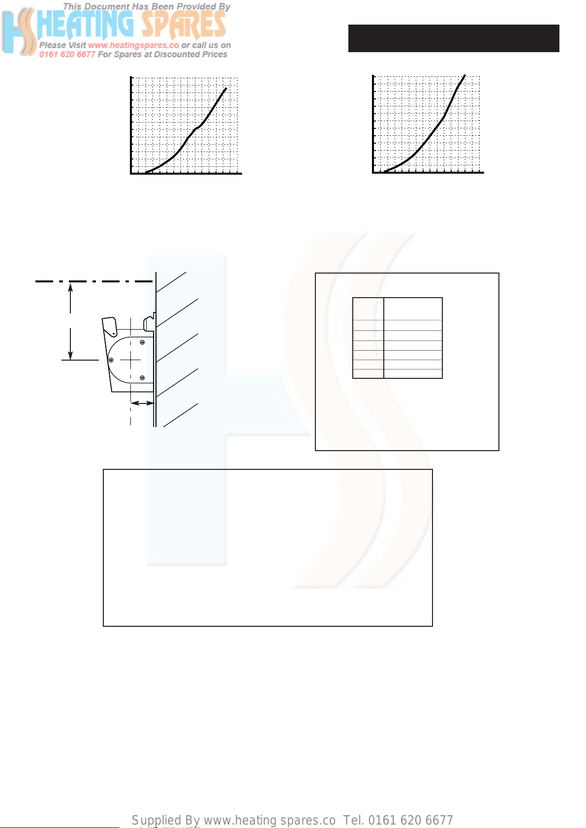
3.0 Technical Data
7
(4) 10
(8) 20
(16) 40
(24) 60
(12) 30
(20) 50
(28) 70
(32) 80
(36) 90
(40) 100
(44) 110
(48) 120
2 4 6 8 10121416182022
Water Flow Rate litres / min
Pressure Drop mbar (in wg)
24262830
(52) 130
(4) 10
(8) 20
(16) 40
(24) 60
(12) 30
(20) 50
(28) 70
(32) 80
(36) 90
(40) 100
(44) 110
(48) 120
2 4 6 8 10121416182022
Water Flow Rate litres / min
Pressure Drop mbar (in wg)
24262830
(52) 130
30, 40 and 50 models
60, 70 and 80 models
Hydraulic Resistance Charts
• This appliance is only intended for installation on a governed supply.
• PMS = 3 bar pressure class 2
• Max CH water pressure 3 bar
• Type C
12C32C52
• Nox class 1
• Appliance category
I
2H
2H - G20 - 20mbar
• Ref: 86/AU/588
• Burner Injector Sizes: 30=B31 40=B32 50=B33 60=B34 70=B35 80=B36
• This boiler is designed to operate at a maximum water temperature of 85° C.
68mm
Model Seasonal Efficiency
(SEDBUK) (%)
30 79.4
40 78.4
50 78.0
60 78.5
70 78.2
80 78.7
This value is used in the UK Government’s Standard
Assessment Procedure (SAP) for energy rating of
dwellings. The test data from which it has been
calculated have been certified by 0086.
SEDBUK Declaration For Solo 3 PFL System
All Models
Top of Outercase
120mm
Supplied By www.heating spares.co Tel. 0161 620 6677
4.0 System Details
8
4.1 Water Circulating Systems
Water Circulating Systems
1. The appliance is suitable for fully pumped
sealed systems only.
The following conditions should be observed
on all systems:
• The boiler must not be used with a direct
cylinder.
• Drain cocks should be fitted to all system low
points.
• All gas and water pipes and electrical wiring
must be installed in a way which would not
restrict the servicing of the boiler.
• Air vents should be fitted to all system high
points.
• All components used in the system must be
suitable for operation at 110°C (230°F).
4.2 Treatment of Water Circulating Systems
• All recirculatory water systems will be subject to
corrosion unless an appropriate water treatment is
applied. This means that the efficiency of the system
will deteriorate as corrosion sludge accumulates
within the system, risking damage to pump and
valves, boiler noise and circulation problems.
• For optimum performance after installation this
boiler and its associated central heating system must
be flushed in accordance with the guidelines given in
BS 7593:1992 “Treatment of water in domestic hot
water central heating systems”.
• This must involve the use of a proprietary cleanser,
such as BetzDearborn Sentinel X300 or X400, or
Fernox Superfloc. Full instructions are supplied with
the products, but for immediate information please
contact BetzDearborn (0151 420 9563) or Fernox
(01799 550 811) directly.
• For long term protection against corrosion and
scale, after flushing it is recommended that an
inhibitor such as BetzDearborn Sentinel X100, or
Fernox MB-1 or Copal is dosed in accordance with
the guidelines given in BS 7593:1992.
Failure to flush and add inhibitor to the system
may invalidate the appliance warranty.
• It is important to check the inhibitor concentration
after installation, system modification and at every
service in accordance with the manufacturer’s
instructions. (Test kits are available from inhibitor
stockists.)
• For information or advice regarding any of the
above contact the Baxi Helpline.
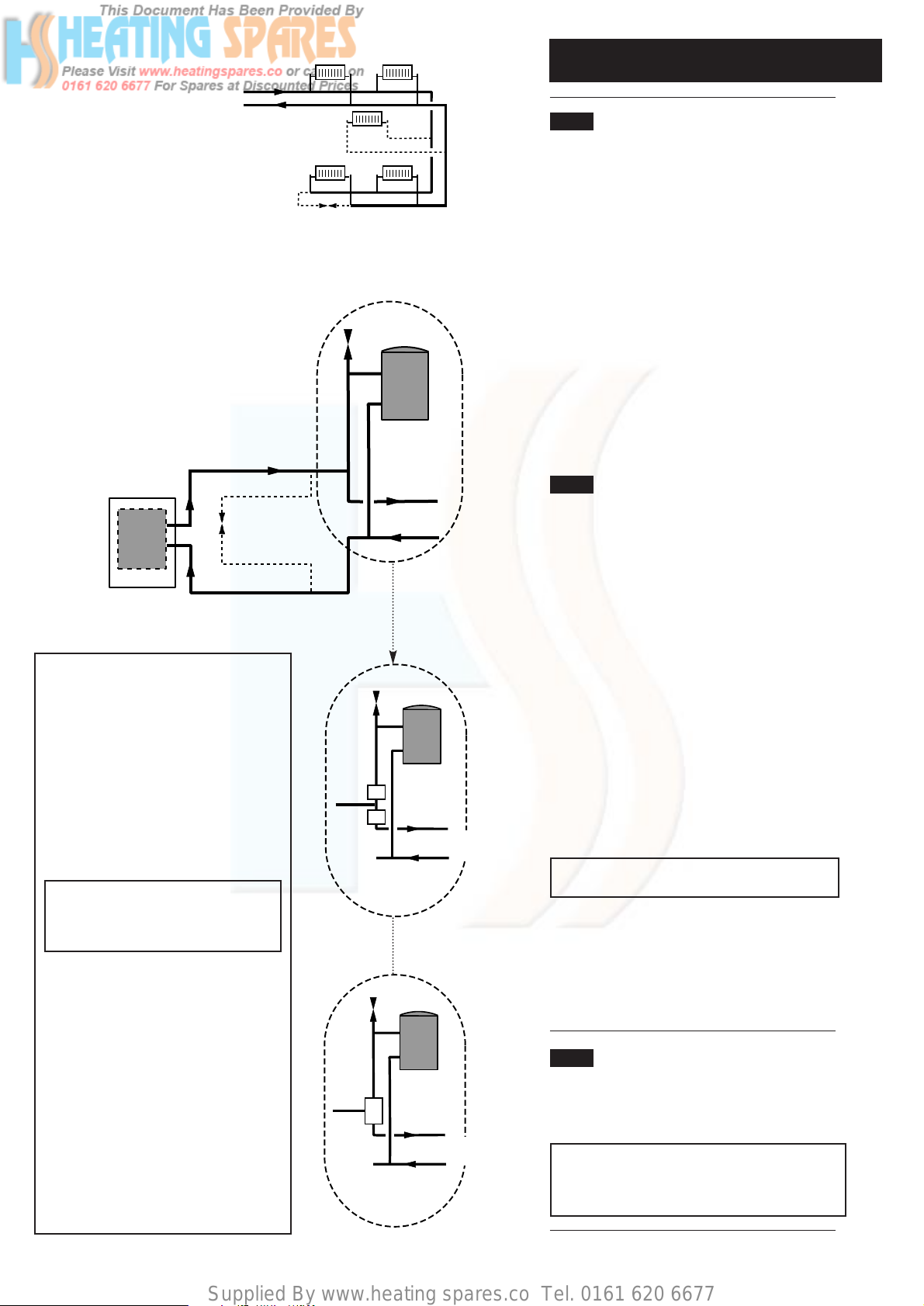
4.3 Bypass Requirements
1. The boiler is fitted with a pump overrun device
which allows the removal of residual heat from the
boiler.
NOTE: The pump overrun will operate for
approximately 8 minutes. The system design must
therefore always provide an open circuit for water
to circulate between the boiler flow and return.
Typical Systems
Arrangement
Option A
Boiler
Air Vent
Radiator
Circuit
Fully Pumped System
Air
Vent
Radiator
Circuit
Twin Zone
Valve System
Air
Vent
Radiator
Circuit
3 Port Divertor
Valve System
Option B
Radiator
Circuit
Option C
Fig. 4a
Fig. 4b
Fig. 4c
Fig. 4d
Examples of systems which require a
bypass are:-
a) A system controlled by non-electrical
valves e.g. mechanical thermostatic control
valves both on the radiators and the hot
water circuit.
b) A system using twin zone valves (e.g.
Honeywell 'S' Plan) (Fig. 4c).
c) A system using a 3 port divertor valve
(Fig. 4d) does not normally require a
bypass therefore this system is
recommended. The exception to this is
where thermostatic radiator valves are used
and then a bypass is required.
NOTE: For ‘S’ Plan systems the bypass
flow circuit must be situated between
pump and zone valves as option A
shows (Fig. 4b).
The bypass circuit can be:-
a) For all boilers a minimum of 6 metres of
22mm copper pipe, (measured between the
boiler flow and return connections). It
should be fitted with a lock shield valve
opened at least 1 full turn or a proprietary
bypass valve set to give a minimum flow
rate of 8 litres/min (1.8 gal/min) (Option C,
Fig. 4a & Option A, Fig. 4b).
b) A radiator fitted with lock shield valves.
The radiator output should be a minimum of
800 watts (2,700 Btu/h). Typically a
convector type radiator with an area of
3750 cm2(4 sq ft) is adequate (Option B,
Fig. 4a).
c) Any circuit that provides the same
operating conditions as option A or option B
(Figs. 4a & 4b).
Supplied By www.heating spares.co Tel. 0161 620 6677
4.0 System Details
9
4.4 Pipework
1. The sizes of flow and return pipes from the
boiler should be determined by normal methods,
according to the requirements of the system.
2. The connections to the boiler are 22mm copper
tails.
4.5 System Components
1. All components used in the system must be
suitable for operation at 110° C (230° F) and at
the pressure allowed by the safety valve.
4.6 System Controls
1. For optimum operating conditions, the heating
system into which the boiler is installed should
include a control system.
2. Such a system will comprise of a timer control
and separate room or cylinder thermostats as
appropriate. (An integral twin channel programmer
is available as an optional extra).
3. The boiler should be controlled so that it
operates on demand only.
4. Operation of the system under control of the
boiler thermostat & TRV’s only does not produce
the best results.
4.7 Thermal Stores & Heat Stores
1. If a thermal store or heat store is being used, it
should be one approved for use with the Baxi Solo
3 PFL System Boiler.
Supplied By www.heating spares.co Tel. 0161 620 6677
4.0 System Details
10
4.8 System Filling and Pressurising
1. A filling point connection on the central heating
return pipework must be provided to facilitate initial
filling and pressurising and also any subsequent
water loss replacement/refilling.
2. The filling method adopted must be in
accordance with all relevant water supply bye-laws
and use approved equipment.
3. Your attention is drawn to: IRN 302 and Byelaw
14.
4. The sealed primary circuits may be filled or
replenished by means of a temporary connection
(Filling Loop) between the circuit and a supply
pipe, provided a WRC approved double check
valve or some other no less effective backflow
prevention device is permanently connected at the
inlet to the circuit and the temporary connection
(Filling Loop) is removed after use (Fig. 5).
4.9 Expansion Vessel
1. The appliance expansion vessel is pre-charged
to 1 bar (10 lb/in
2
). Therefore, the minimum cold fill
pressure is 1 bar. The vessel is suitable for correct
operation for system capacities up to 125 litres
(27.5gal). For greater system capacities an
additional expansion vessel must be fitted - refer to
BS 7074 Pt 1.
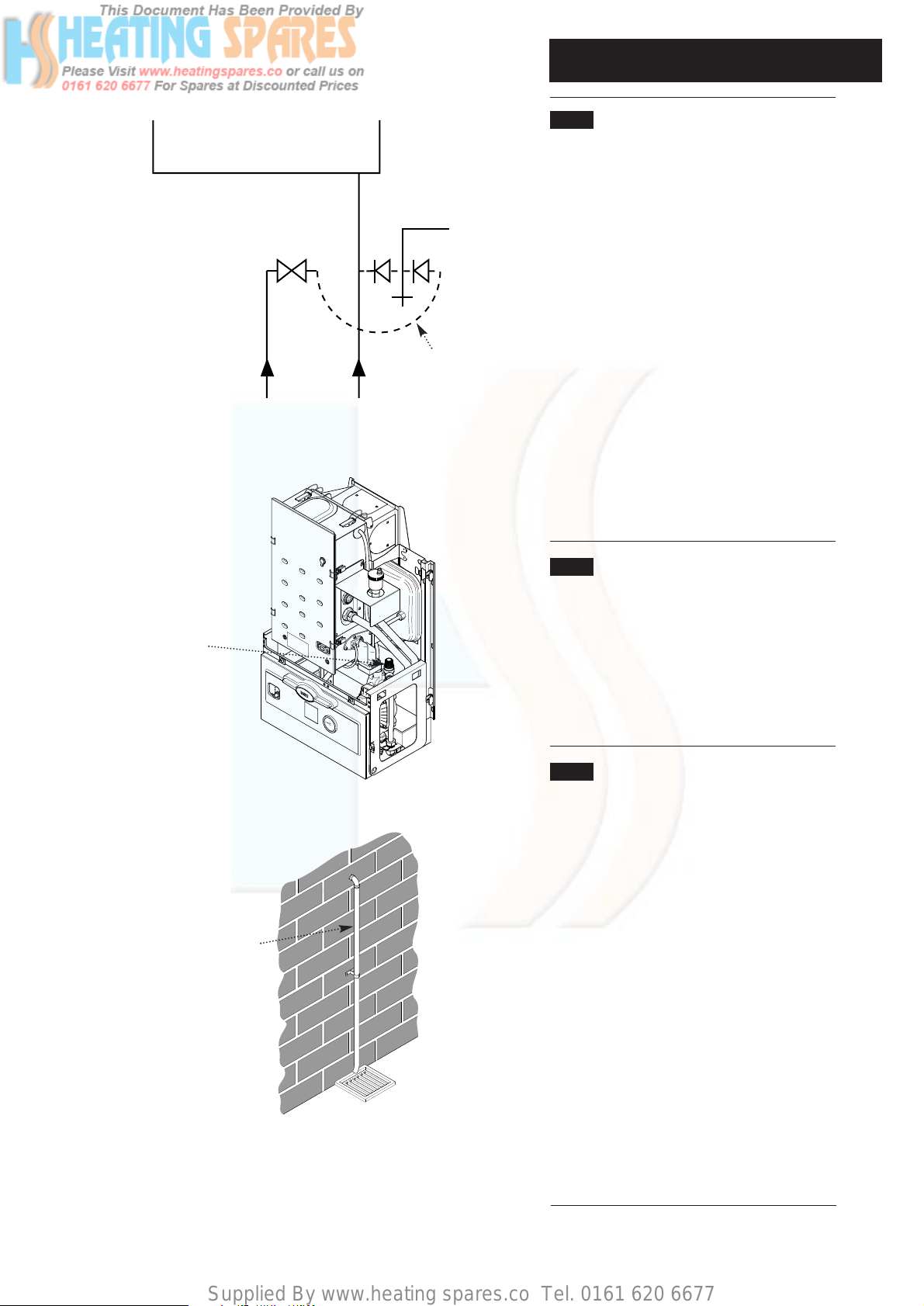
4.10 Pressure Relief Valve (Figs. 6 & 7)
1. The pressure relief valve is set at 3 bar,
therefore all pipework, fittings, etc. should be
suitable for pressures in excess of 3 bar.
2. The pressure relief discharge pipe should be not
less than 15mm dia, run continuously downward,
and discharge outside the building, preferably over
a drain. It should be routed in such a manner that
no hazard occurs to occupants or causes damage
to wiring or electrical components. The end of the
pipe should terminate facing down and towards the
wall.
3. The discharge must not be above a window,
entrance or other public access. Consideration
must be given to the possibility that under fault
conditions boiling water/steam could discharge
from the pipe.
4. The pressure relief valve must not be used for
draining the system/boiler.
Discharge Pipe
Fig. 5
Stop Valve
Double
Check
Valve
Mains
CH
Return
Filling Loop
Fig. 7
Fig. 6
Pressure Relief Valve
Supplied By www.heating spares.co Tel. 0161 620 6677
5.0 Site Requirements
11
5.1 Location
1. The appliance may be fitted to any suitable wall
with the flue passing through an outside wall and
discharging to atmosphere in a position permitting
satisfactory removal of combustion products and
providing an adequate air supply. The appliance
should be fitted within the building unless otherwise
protected by a suitable enclosure ie. garage or
outhouse. (The appliance may be fitted inside a
cupboard. Cooling ventilation and insulation of the
cupboard are not required, see section 5.5.)
2. If the appliance is fitted in a room containing a bath
or shower reference must be made to the Current
I.E.E. Wiring Regulations and Building Regulations. If
the appliance is to be fitted into a building of timber
frame construction then reference must be made to
the Institute of Gas Engineers document UP7 (“Guide
for Gas Installation in Timber Framed Dwellings”).
3. Recommendations for flues are given in BS 5440
Part 1.
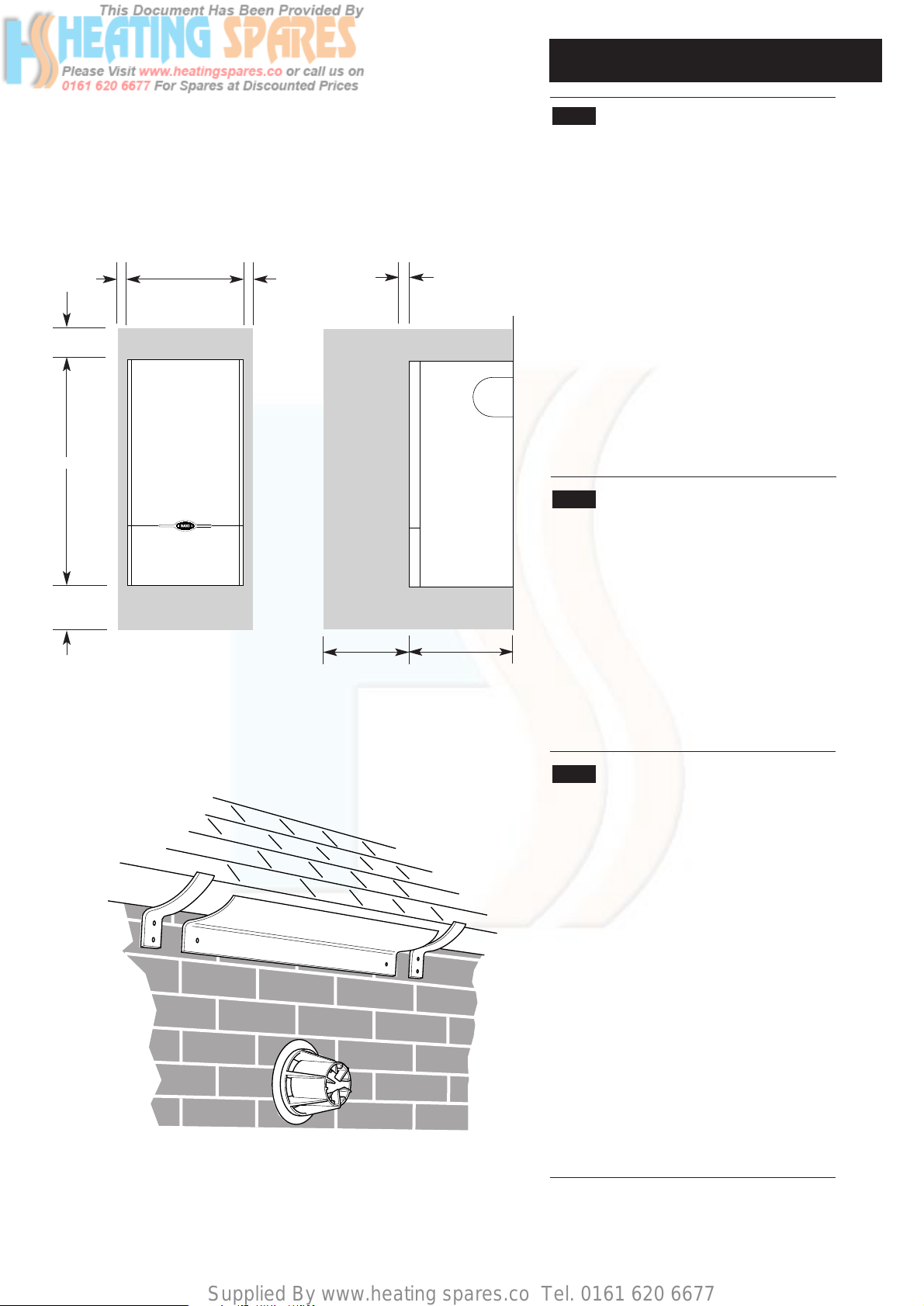
5.2 Minimum Clearances (Fig. 8)
1. A flat vertical area is required for the installation of
the boiler.
2. These dimensions include the necessary
clearances around the appliance for case removal,
spanner access and air movement. Additional
clearances may be required for the passage of pipes
around local obstructions such as joists running
parallel to the front face of the appliance.
3. If fitted inside a cupboard the clearance of 500mm
shown is only necessary when the cupboard door is
open. A clearance of 5mm (3/16in) is required when
the door is closed.
5.3 Flue Position
1. For installations where the flue terminal is
inaccessible from the outside, an internal fitting kit is
available. This can be obtained free of charge from
your local merchant.
2. The following guide lines indicate the general
requirements for siting balanced flue terminals.
3. If the terminal is fitted within 1 metre (39in) of a
plastic gutter, within 500mm (191/2in) of a painted
eave or a painted gutter, an aluminium shield of at
least 1 metre (39in) long should be fitted to the
underside of the gutter or painted surface. An air
space of 5mm (3/16in) should be left between shield
and gutter (Fig. 9).
4. If the terminal discharges onto a pathway or
passageway, check that combustion products will not
cause a nuisance and that the terminal will not
obstruct the passageway.
5. If the outer surface of an outside wall is of
combustible material, it should be protected by fitting
the flue trim provided.
Fig. 8
Fig. 9
500mm for servicing
5mm during operation
5mm5mm
850mm
50mm
100mm
Aluminium
Shield
490mm
320mm
Supplied By www.heating spares.co Tel. 0161 620 6677
5.0 Site Requirements
12
5.3 Flue Position (Cont)
WARNING - The addition of anything that may
interfere with the normal operation of the
appliance (e.g. FLUE DAMPERS,
ECONOMISERS,etc.) without the express
written permission of Baxi UK Limited could
invalidate the appliance warranty and infringe
the GAS SAFETY (Installation and Use)
REGULATIONS.
If a terminal is less than 2 metres (78
3
/4in)
above a balcony, above ground or above a flat
roof to which people have access then a
suitable terminal guard must be provided.
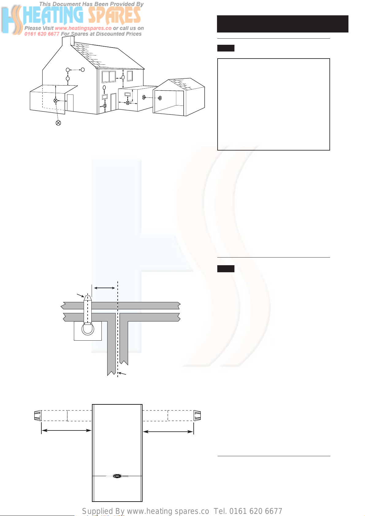
6. The flue terminal position must always be
in accordance with the current edition of B.S.
5440 Part 1, and either Part J of the Building
Regulations England and Wales or Part F of
the Building Standards (Scotland)
Regulations as appropriate.
7. Table 2 and Fig. 10 show the positioning of the
flue terminal relative to buildings and other
structures.
8. The dimensions of the flue terminal are shown
in Section 3.0 Technical Data.
5.4 Flue Dimensions
1. Flue extensions are available as optional
extras for installations up to 3 metres
horizontal.
2. Vertical flue kits are available up to 4
metres in length. Vertical twin flue kits are
available up to 15 metres in length.
3. The standard telescopic flue is suitable for use
with rear flue lengths between 100mm (4in) and
500mm (19
5
/8in).
4. Where it is intended to pass the flue through a
combustible wall or timber framed dwelling,
reference should be made to the Institute of Gas
Engineers document UP7 - Guide for Gas
Installations in Timber Framed Dwellings.
5. If the flue is more than 1 metre (39
3
/8in) long, it
is required that it is supported.
6. All above dimensions are taken from the
respective faces of the outer case.
Fig. 11
Maximum lengths for side flue using the standard telescopic flue kit
355mm
335mm
Table. 2
Fig. 10
L
G
G
E
J
D
K
G
A
A
D
F
H,I
B,C
F
Likely flue positions requiring
a flue terminal guard
M
N
Horizontal Terminal Position with Minimum Distance (mm)
A Directly below an openable window, air vent or any other
ventilation opening. 300
B Below gutter, drain/soil pipe. 150
C Below eaves. 200
D Below a balcony/car port roof. 200
E From vertical drain pipes and soil pipes. 150
F From internal or external corners. 300
G Above adjacent ground or balcony level. 300
H From a surface or boundary facing a terminal. 600
I Facing a terminal. 1200
J From opening (door/window) in carport into dwelling. 1200
K Vertically from a terminal on the same wall. 1500
L Horizontally from a terminal on the same wall. 300
M Above an opening, air brick, opening window etc. 300
N Horizontally to an opening, air brick, opening window etc. 300
NOTE: Scotland Only - The distance from a fanned draught appliance
terminal installed at right angles to a boundary may not be less than
300mm in accordance with the diagram below.
300 min
Terminal
Assembly
Top View Rear Flue
Property Boundary Line
Supplied By www.heating spares.co Tel. 0161 620 6677
5.0 Site Requirements
13
5.5 Ventilation of Compartments
1. Where the appliance is installed in a cupboard
or compartment, no air vents are required.
NOTE: The ventilation label on the front of the
outer case MUST NOT BE REMOVED when
the appliance is installed in a compartment or
cupboard.
2. B.S. 5440 Part 2 Clause 4.2 refers to room
sealed appliances installed in compartments.
This appliance will run sufficiently cool without
ventilation.
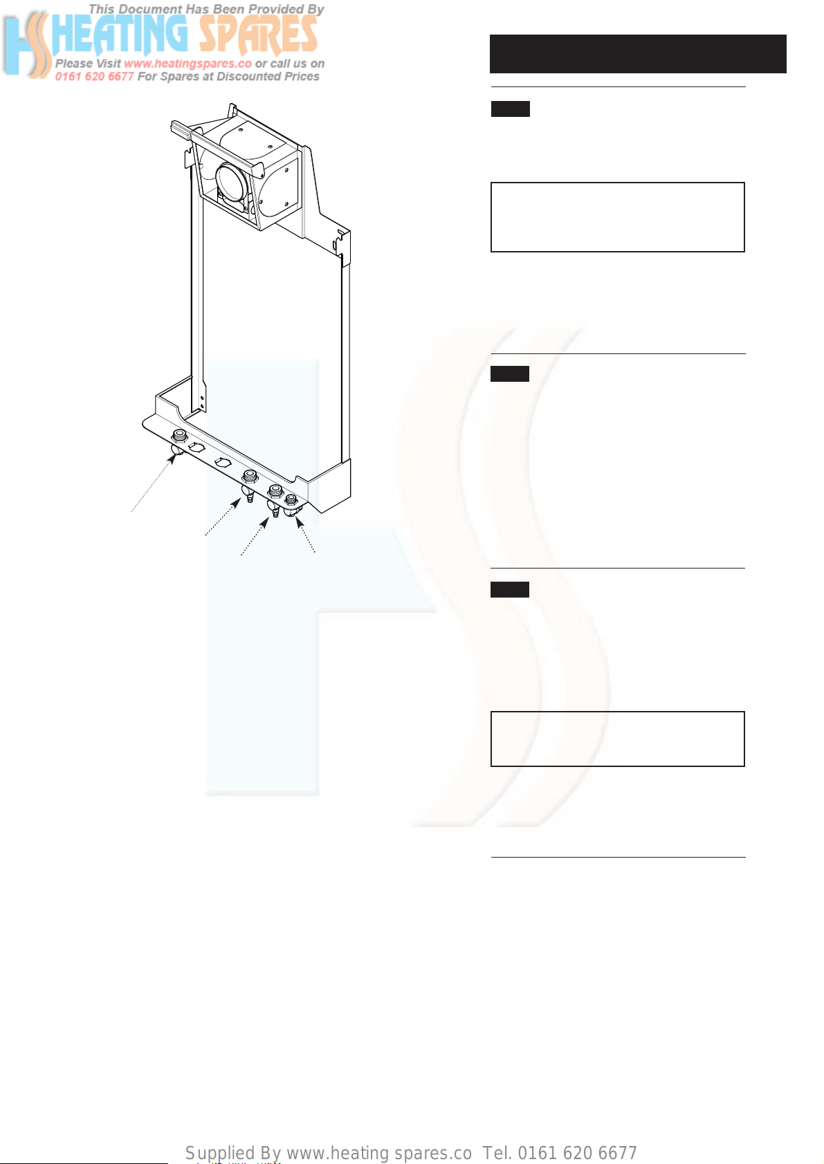
5.6 Gas Supply
1. The gas installation should be in accordance
with BS 6891.
2. The connection of the appliance is a 22mm
copper tail on the tap rail (Fig. 12).
3. The pipework should be sized to account for
the distance of the appliance from the meter, the
pipe routing and maximum input of the appliance.
5.7 Electrical Supply
External wiring must be correctly earthed,
polarized and in accordance with CURRENT
I.E.E. WIRING REGULATIONS.
The mains supply is 230V ~ 50Hz fused at 5A.
NOTE: The method of connection to the
electricity supply must facilitate complete
electrical isolation of the appliance.
Connection may be made via a fused doublepole isolator with a contact separation of a least
3mm in all poles and serving the appliance and
system controls only.
Fig. 12
Gas Connection
Flow Connection
Return Connection
Pressure Relief
Connection
Supplied By www.heating spares.co Tel. 0161 620 6677
6.0 Installation
14
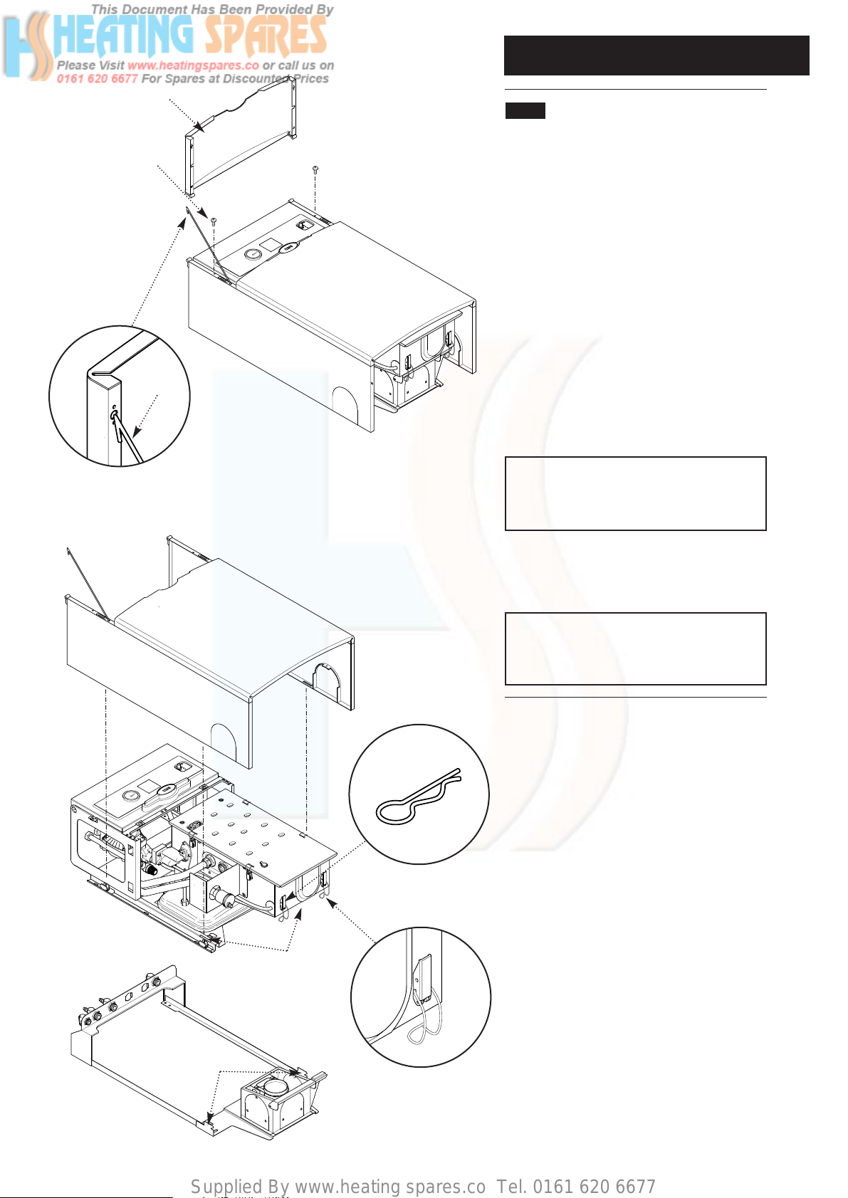
6.1 Initial Preparation
1. Open the hinged lower door panel and
carefully disengage the door stay. Remove the
door by opening it 90° and pulling forward
(Fig. 13).
2. Remove the 2 screws holding the outer case
to the combustion box (Fig. 13).
3. Place the outer case in a safe place until
required.
4. Remove the R clip from the latch securing the
combustion box to the back plate and release
the latches (Fig. 14a & 14b).
5. Lift and remove the combustion box and
backplate from the wall plate (Fig. 14). Place the
combustion box and backplate on its back.
IMPORTANT - When installing a Solo 3
System with a rear flue see section 6.2 Fan
Outlet Restrictor before continuing the
installation.
6. Proceed to the relevant section for flueing the
appliance either to the Rear, Left, Right or
Vertically.
NOTE: For Vertical flueing or flue lengths
greater than standard, the relevant optional
extra kits must be obtained and their
instructions followed.
Fig. 13
Lower Door Panel
Outer Case
Fixing Screw
Retaining Latch
Wall Plate
Back Plate Slots
Hooks
‘R’ Clip
Fig. 14
Fig. 14a
Fig. 14b
Door Stay

Supplied By www.heating spares.co Tel. 0161 620 6677
6.0 Installation
15
6.2 Initial Preparation (continued)
1. Remove the fixing template (Fig. 14c) from the
carton.
2. After considering the site requirements
(see Section 5.2) position the template on the
wall ensuring it is level both horizontally and
vertically. If it is desired that the appliance is
positioned centrally between two points, mark
the wall accordingly and align the template
centreline with this mark.
3. Mark at least four suitable fixing holes for the
wall plate. Preferably the two at either side of the
flue airbox should be used. Fixing points X and Y
can be used for additional securing of the
combustion box assembly to the wall. Points X
must be used when the optional security kit is
used.
4. Drill the anchorage holes 63mm (2
1
/2in) deep
to accept suitable wall plugs.
5. Mark the centre of the flue hole (rear exit). For
side exit, mark as shown. If required, mark the
position of the gas, water and pressure relief
discharge pipes. Remove the template.
6. Cut the hole for the flue (minimum diameter
107mm).
7. For rear flue applications continue as
described in Section 6.4. Side flue installations
are covered in Section 6.7.
Fig. 14c
Vertical Flue
Centre Line
Horizontal Flue
Centre Line
Solo 3 System Boiler
GAS SUPPLY FLOW RETURN PRESSURE
RELIEF
100 mm
Minimum
Clearance
50 mm
Minimum Clearance
5 mm
Minimum Clearance
From Outercase To
Edge Of Template
Fixing Points marked X and Y can be
used for additional securing of the
combustion box to the wall.
Points X must be used when optional
security bolts are fitted
TEMPLATE
Boiler
Center Line
Profile of
Outercase
5 mm
Minimum Clearance
From Outercase To
Edge Of Template
Side And Top
Flue Template
X
X
X
X
Y
Y
Fixing Template
 Loading...