

Baxi Solargen PHOTOVOLTAIC User Manual
Solargen
Please read these instructions before installing or commissioning.
This Solar Photovoltaic system should only be installed by a competent person.
PLEASE LEAVE THESE INSTRUCTIONS WITH THE USER FOR SAFE KEEPING.
PHOTOVOLTAIC MANUAL
© BAXI Heating UK Ltd 2011


Solargen solar PV
3
Index.........................................................................................................................
Table Index................................................................................................................
Figure Index..............................................................................................................
Safety information.....................................................................................................
1.INTRODUCTION...................................................................................................
1.1.Preface...............................................................................................................
1.2.Supply and Packaging........................................................................................
1.3.Security Warnings...............................................................................................
1.4.Installation Standards.........................................................................................
1.4.1. Safety and Care..............................................................................................
2.KIT CONTENTS..................................................................................................
3.PV KIT INSTALLATION.......................................................................................
3.1.PV module........................................................................................................
3.1.1.Choosing the site...........................................................................................
3.1.2.Installation guidelines.....................................................................................
3.1.3.Mechanical characteristics..............................................................................
3.1.4 Mechanic Installation.....................................................................................
3.2.PV Generator....................................................................................................
3.2.1.PV series connection.....................................................................................
3.2.2.PV module fastening......................................................................................
3.3.DC Electric Box (available as an optional extra)...............................................
3.3.1.Components....................................................................................................
3.3.2.Location..........................................................................................................
3.3.3.Electric Scheme.............................................................................................
3.3.4.Crimp connectors...........................................................................................
3.4.Inverter..............................................................................................................
3.4.1.Installation requirements................................................................................
3.4.2.Clearances.....................................................................................................
3.4.3.Position..........................................................................................................
3.4.4.Mounting the inverter.....................................................................................
3.4.5.Connecting PV strings to the inverter.............................................................
3.5. AC electric box (available as an optional extra)...............................................
3.5.1.Description.....................................................................................................
3.5.2.Location..........................................................................................................
3.5.3.Single line diagram.........................................................................................
3.6.Connection to the grid.......................................................................................
3.6.1.AC cable size.................................................................................................
3.7.Energy meter.....................................................................................................
3.7.1.Warnings........................................................................................................
3.7.2.Environmental requirements..........................................................................
3.7.3.Cabling...........................................................................................................
3.7.4.Cable specication.........................................................................................
3.7.5.Installation data..............................................................................................
3.7.6.Dimensions and mounting..............................................................................
3.8.Electrical diagrams............................................................................................
4.PV SYSTEM PROTECTION................................................................................
4.1.Protection against lightening.............................................................................
4.1.1.Array Frame Earthing Decision Tree..............................................................
4.2.Protection against direct contact.......................................................................
4.3.Protection against indirect contact....................................................................
4.4.Warning and note signs.....................................................................................
4.4.1.Location of the safety labels...........................................................................
5.PV SYSTEM COMMISSIONING..........................................................................
5.1.Connect a PV system........................................................................................
5.2.Disconnect the PV system................................................................................
5.3.Security notes...................................................................................................
6.MAINTENANCE MANUAL.................................................................................
6.1.General information..........................................................................................
6.2.PV generator....................................................................................................
6.3.Inverter.............................................................................................................
6.3.1.Safety Warnings............................................................................................
6.3.2.Inverter operation conditions.........................................................................
7.SUPPORTING STRUCTURE ASSEMBLING MANUAL....................................
7.1.Flat roof............................................................................................................
7.2.Parallel to pitched roof......................................................................................
8.WARRANTY........................................................................................................
9.MAINTENANCE..................................................................................................30
10.NOTES..............................................................................................................31
Index
3
4
5
6
8
8
8
8
8
9
10
11
11
11
11
11
11
12
12
12
13
13
13
13
13
14
14
14
14
15
15
16
16
16
16
16
16
17
17
17
17
17
17
17
18
19
19
19
20
20
20
20
21
21
21
21
22
22
22
22
22
22
23
26
26
29
© Baxi Heating UK Ltd 2011. All rights reserved. No part of this publication may be reproduced or
transmitted in any form or by any means, or stored in any retrieval system of any nature (including
in any database), in each case whether electronic, mechanical, recording or otherwise, without
prior written permission of the copyright owner, except for permitted fair dealing under Copyrights,
Designs and Patents Act 1988.
Applications for the copyright owner’s permission to reproduce or make other use of any part of
this publication should be made, giving any details of the proposed use to the following address:
The Company Secretary, Baxi Heating UK Ltd, Brooks House, Coventry Road, Warwick CV34 4LL.
Full acknowledgement of author and source must be given.
WARNING: Any person who does any unauthorised act in relation to a copyright work may be
liable to criminal prosecution and civil claims for damages.

Solargen solar PV
4
Table index
Index
Table 1. Equipment contained within the photovoltaic kit...................................
Table 2. Equipment available as an optional extra.............................................
Table 3.
Table 4. Inverter installation – Minimum distances.............................................
Table 5. AC cable cross sections.......................................................................
Table 6. Relation between the kits and the inverter power................................
Table 7. Maximum earth resistance....................................................................
Table 8. Spacing between A-frames..................................................................
Table 9. Spacing between the roof supports.....................................................
10
10
11
14
16
18
20
23
27
Mechanical specications.....................................................................

Solargen solar PV
5
Index
Figure 1. Handling.................................................................................................
Figure 2. Fastening the modules to the roof mountings.......................................
Figure 3. Module´s physical dimensions..............................................................
Figure 4. Module Fixing........................................................................................
Figure 5. Cable Routing.......................................................................................
Figure 6. PV module junction box........................................................................
Figure 7. PV series connection............................................................................
Figure 8. Diagram for the module´s ground connection......................................
Figure 9. Example of PV mounting......................................................................
Figure 10. DC Electric Box.....................................................................................
Figure 11. DC Electric Box location.......................................................................
Figure 12. Correct crimping pliers..........................................................................
Figure 13. Example of a single line scheme for the DC Electric Box.....................
Figure 14. Inverter installation – requirements.......................................................
Figure 15. Minimum distances...............................................................................
Figure 16. Mounting position..................................................................................
Figure 17. Mounting the inverter............................................................................
Figure 18. Connecting PV strings to the inverter...................................................
Figure 19. AC electric Box.....................................................................................
Figure 20. Example of a single line diagram of the AC electric box.......................
Figure 21. Energy meter.........................................................................................
Figure 22. Meter terminal layout............................................................................
Figure 23. Meter xing points.................................................................................
Figure 24. 1.32 - 2.64 kWp unilar electrical diagram............................................
Figure 25. 3.96 kWp unilar electrical diagram......................................................
Figure 26. Ex. electrical diagram with AC and DC electrical box...........................
Figure 27. PV system protection............................................................................
Figure 28. Array Frame earthing decision tree......................................................
Figure 29. Safety Labels........................................................................................
Figure 30. Warning Sign – Injury or death risk.......................................................
Figure 31. PV system startup steps.......................................................................
Figure 32. Steps for the string disconnection from the inverter..............................
Figure 33. Operational state of the inverter...........................................................
Figure 34. A-frame assembly.................................................................................
Figure 35. A-frame mounting................................................................................
Figure 36. Spacing between A frame proles........................................................
Figure 37. Transverse prole mounting.................................................................
Figure 38. A frame bracing....................................................................................
Figure 39. PV module centre clamp......................................................................
Figure 40. PV module side clamps & plastic end caps..........................................
Figure 41. Typical structure.....................................................................................
Figure 42. Prole connections...............................................................................
Figure 43. Anchors for at tiles.............................................................................
Figure 44. Anchors for mechanical tiles................................................................
Figure 45. Anchors xed on a pitched roof...........................................................
Figure 46. Standard Mounting kit for portrait installations.....................................
Figure 47. Standard Mounting kit Landscape accesory for Lands. installations...
Figure 48. Transverse prole mounting to the roof brackets.................................
Figure 49. PV module centre clamps....................................................................
Figure 50. PV modules side clamps......................................................................
Figure 51. End covers for the transverse proles..................................................
Figure 52. Structure for 2 PV modules..................................................................
Figure 53. Prole connectors................................................................................
Figure index
9
11
11
11
11
12
12
12
12
13
13
13
13
14
14
14
15
15
16
16
17
17
17
18
18
18
19
19
20
20
21
21
22
23
23
23
24
24
24
25
25
25
26
26
26
27
27
27
27
27
28
28
28

Solargen solar PV
6
Safety information
In order to reduce the number of deaths and major accidents attributable to work at height, the health and Safety Executive has introduced
comprehensive regulations and guidance that should be followed by all
businesses working at height.
We consider in the following paragraphs some of the main features of the
regulations and guidance. This is, however, only a limited summary and
it is recommended that all businesses planning on undertaking solar PV
installations obtain a copy of the regulations and guidance issued by the
Health and Safety Executive and carefully consider the contents.
The regulations and guidance state that you are required to carry out
a risk assessment for all work conducted at height and to put in place
arrangements for:
• Eliminating or minimising risks from work at height.
• Safe systems of work for organising and performing work at height.
• Safe systems for selecting suitable work equipment.
• Safe systems for protecting people from the consequences of work at
height.
The regulations and guidance highlight a hierarchy for safe work at
height:
• Avoid the risk by not working at height if practicable.
• Prevent falls, where it is not reasonably practicable to avoid work at
height; you are required to take suitable and sufficient steps to prevent
the risk of a fall including selecting the most suitable work equipment (in
accordance with the regulations).
• Mitigate the consequences of a fall; where tha risk of a person or object
falling still remains, take suitable and sufficient measures to minimise the
distance and consequences of any fall.
Collective protection measures, such as guard rails on scaffold, should
be given priority over personal protection measures, such as safety harnesses.
Within the regulations´framework, you are required to:
1) Assess the risk to help you decide how work safely.
2) Follow the hierarchy for safe work at height (i.e.avoid, prevent and
mitigate).
3) Plan and organise your work properly, taking account of weather conditions and the possibility of emergencies.
4) Make sure those working at height are competent.
5) Make use of appropriate work equipment.
6) Manager the risks from working on or around fragile surfaces and from
falling objects.
7) Inspect and maintain the work equipament to be used and inspect the
place where the work will be carried out ( including access and egress).
When preparing to install a solar Photovoltaic system, it is required that
you perform a risk assessment in relation to work at height and plan how
you will organise your work, taking into account the site, the weather
conditions and the experience and competence of colleagues or and the
experience and competence of colleagues or contractors who may be
working at height with you.
Risk Assessments
The HSE has published a number of very useful free publications that
advise how to undertake risk assessments.
Two of these that you should obtain are:
Five Steps to Risk Assessment.
A Guide to Risk Assessment Requirements.
The five steps outlined in the HSE leaflet are:
Step 1: Look for the hazards
This will mean looking at the site and identifying significant hazards. These could be features such as a steep roof, a fragile surface where the
collectors may be mounted, unecen ground or obstructions where access
to the roff might be required.

Solargen solar PV
7
Step 2: Decide who may be harmed and how
This might mean considering the particular risks that young workers or
trainees might face and thinking about the residents of the household or
visitors who could be hurt by your activities.
Step 3: Evaluate the risks and decide which precautions should be made.
You should consider how likely it is that each hazard will cause harm, decide which precautions you might take and then assess, after you have
taken those precautions, whether the remaining risk will be high, medium
or low.Where you identify remaining risks, you should consider which
further action you could take to control the risks so thar harm is unlikely.
Step 4: Record your ndings
If you have fewer than ve employees you do not need to write anything
down, though it is useful to keep a written record of what you have done.
If you employ ve or more people you must record the signicant ndings
of your assessment. You must also tell your employees about your n-
dings. You need to be able to show that a proper check was made, that
you considered who might be affected, that you dealt with all the obvious
signicant hazzards, that the precautions you propose are reasonable
and that the remaining risk is low.
Step 5: Review your assessment if necessary
Each solar Photovoltaic installation may bring its own challenges and
present its own particular hazards. You should therefore be careful no
to rely on a “standard” risk assessment for installing a solar Photovoltaic system in a house, but at the preparation stage you should consider
where scaffold or other access equipament might be positioned and look
out for any obvious obstacles to this, such as a conservatory or porch.
In addition to the risks associated with work at height, you should also
consider the risks associated with lifting and carrying solar collectors,
using electric drills and using blow lamps or blow torches for soldering.
This is not an exclusive list and you should consider all aspects
Safety information
Solargen solar PV
8
1. INTRODUCTION
1.1. Preface
Attention
The installation of this photovoltaic kit must only be performed by people
qualied to the current standards and who are competent to do so.
Any solar PV system must comply with heath & safety requirements,
BS7671 and other relevant standards & codes of practice (working at
heights etc).
Other standards which must be adhered to are:
• Engineering Recommendation G83/1 (2003) – Recommendations for
the connection of small scale embedded generators (up to 16A per phase) in parallel with the public low voltage distribution networks
• IEE Guidance Note 7 to BS7671 – Special Locations, section 12 Solar
Photovoltaic (PV) Power Supply Systems (ISBN 0 8596 995 3, 2003)
This manual is not intended to replace any best practice guides such
as Photovoltaics in Buildings – Guide to the Installations of PV Systems
published by the DTI or any other standards which maybe relevant which
are in force at the time of writing.
1.2. Supply and Packaging
The photovoltaic (PV) kit will be provided in a package properly developed for this purpose.
This package contains the PV modules, inverter, generation meter, protection switch gear, solar cable, connectors and accessories suitable for use with the Baxi roof mountings supplied.
The proles are packaged apart, due to their length.
The package should be transported upright and xed, in order to elimi-
nate any chance of slips and shocks, to avoid damage to the equipment.
Please ensure no materials are placed on top of the packaging.
1.3. Security Warnings
DANGER
Risk of death due to high voltages inside the inverter
All works on the PV System should be performed only by someone qualied to do so, in accordance with CURRENT REGULATIONS & standards.
CAUTION
Risk of burns due to hot parts of the inverter housing
Do not touch the inverter housing during operation.
PV MODULE EARTH CONNECTION
Take into account regulations for earth connection. It is advised to connect all exposed metal parts, including the PV frames to ground via appropriate methods suitable in accordance with BS 7671 current edition.
1.4. Installation Standards
The PV system should be installed in accordance with the current electrical regulations; BS7671.
All the safety standards and regulations in force should be known at the
time of installation.
Baxi Heating UK are not responsible for any damage to the equipment
during installation works..
The PV modules should be carefully installed; predicting possible adver-
se weather conditions which may causes difculties with the installation,
i.e. high winds & rain.
PV modules should be installed facing true South where possible in order
to obtain maximum electrical generation. Slight deviation from South can
be acceptable; this should be checked by a competent person before
commencing with the installation.
Solargen solar PV
9
1.4.1. Safety and Care
During the installation, the following operation and maintenance
recommendations when handling the photovoltaic modules must
be taken in consideration:
1. It is recommended to maintain the modules properly packaged, in-
side the box, on its transport pallet, until the moment of installation.
2. The front surface of the photovoltaic module should remain covered
with an opaque material until all connections are established and
veried.
3. When exposed to sunlight or other light source, the module produ-
ces electricity (in DC current); the association in series of 2 or more
modules produces enough energy to cause fatalities from electrocution in case of contact with active parts of the electrical circuit.
4. Do not touch the terminals of the connectors when the module is
exposed to light sources; take precautions to avoid the contact with
voltages equal to or higher than 30 Volts DC; the installer should not
forget that a string of modules associated in series will have a total
voltage equal to the sum of the individual voltages of the modules.
5. Use appropriate tools for electrical work in installation and mainte-
nance operations.
6. Do not disconnect the wires from the module while it is working; the
risk of accident is very high due to the electric arcs generated, and
it may also damage the product.
7. The modules should only be connected in a dry place with favorable
climatic conditions.
8. DO NOT walk on the module(s), DO NOT place loads on their sur-
faces, DO NOT drop objects on the module, DO NOT knock on the
module with any object.
9. When handling, prevent the dropping of modules; a module with
broken glass cannot be used or repaired.
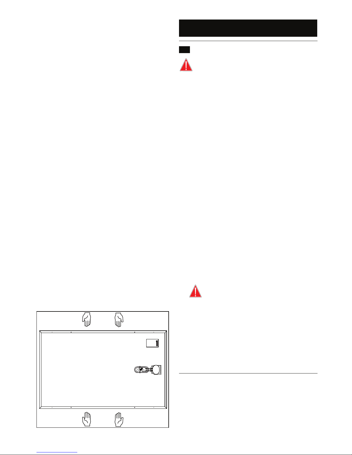
10. The module should always be moved by two people and seized by
the aluminum frame, as shown in (Figure 1).
11. Keep the module away from objects that could damage it.
12. Do not install the module near ammable materials, for example fuel
tanks or areas where there are ammable vapors; the connectors
of the module, if poorly coupled, can generate electric arcs causing
ignition of ammable materials; Keep ammable materials at a minimum distance of 30 cm between the active parts of the electrical
installation, such as connectors or other connection points.
13. Do not bend, damage or place loads on connecting cables and mo-
dule connectors.
14. Do not pierce the aluminum frame, glass or the back protection sur-
face of the module; these actions will void the warranty.
15. NEVER, under any circumstances, open the junction
box of the photovoltaic module; besides the personal safety
risk, exposing the electrical parts of an active photovoltaic
module may compromise the proper functioning of the module.
16. Verify that no other equipment in the facility may cause electrical or
mechanical damage to the module.
17. The installation, operation and maintenance of the module should
be performed only by qualied personnel.
18. Take actions to keep children or outsiders away from any element
of the installation.
19. Do not paint or paste any type of adhesive on the module.
20. Do not dismantle or remove any part of the module.
21. Do not use metal objects, jewelry and accessories during installa-
tion or maintenance of the module.
22. When installing the module, be sure that the cables are always at
the bottom of the junction box.
1. INTRODUCTION
Figure 1. Handling
Solargen solar PV
10
AC Electric Box
DC Electric Box
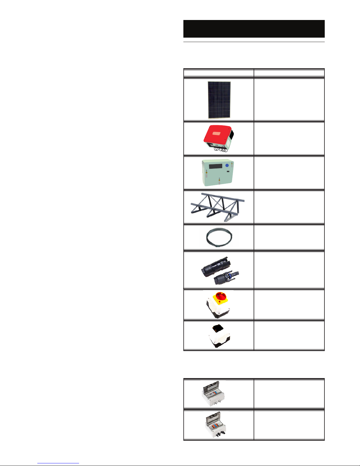
2. KIT CONTENTS
Table 1: Equipment contained within the photovoltaic kit
Image Equipment
PV Module
Inverter
Energy meter
Supporting structure
4mm² Solar Cable
Connectors
Main AC switch
Main DC switch
Table 2: Equipment available as an optional extra.
 Loading...