

Baxi Solaire Super Installation And Servicing Instructions
Supplied By www.heating spares.co Tel. 0161 620 6677
Please leave these Instructions with the user.
Baxi Solaire Super
Gas Fire
Natural Gas
Comp No 236216 - 10/95
Baxi Solaire Super - G.C.No 32 077 36
Installation
And
Servicing
Instructions
Supplied By www.heating spares.co Tel. 0161 620 6677
Installation Instructions – Page 2
INTRODUCTION
The Baxi Solaire Super is a hearth or wall mounted gas fired
room heater with a flame and coal effect. Input at maximum
setting is 5.42kW (18,500 Btu/h) corresponding to a net
output of 3.47kW (11840 Btu/h) approx. The fire is available
for use with Gas Type G20 (Natural Gas) at 20mbar. The fire
is controlled by a control knob positioned on the right hand
side of the case. Ignition is by a piezo spark to the burner.
The control knob has six positions giving a choice of four
output rates
Position - The fire is OFF.
Position - Pilot.
Position 1 - The fire is on low.
Position 2 - The fire is on medium.
Position 3 - The fire is on medium high
Position 4 - The fire is on high.
The outer case has two concealed lamps to illuminate the
artificial coal bed. This light effect is operated by a switch
below the control knob. It may be used with or without the
gas fire.
NOTICE
Discolouration of Wall Surfaces
Most heating appliances generate warm air convection
currents and transfer heat to any wall surface against
which they are situated.
Some soft furnishings (such as blown vinyl wallpapers)
may not be suitable for use where they are subjected to
temperatures above normal room levels and the
manufacturers advice should be sought before using
this type of wall covering adjacent to any heating
appliance.
The likelihood of wall staining from convected air
currents will be increased in environments where high
levels of cigarette smoke or other contaminants exist.
GENERAL
The installation must be carried out by a CORGI Registered
Installer or other competent person and be in accordance
with the relevant requirements of the GAS SAFETY
(Installation and Use) REGULATIONS (as amended), the
BUILDING REGULATIONS (Scotland) (Consolidation), the
LOCAL BUILDING REGULATIONS and the CURRENT
I.E.E. WIRING REGULATIONS. It should also be in
accordance with the relevant BRITISH STANDARD CODES
OF PRACTICE.
B.S. CODES OF PRACTICE
BS 6891 Gas Installation
BS 5871:Part 1 Installation of Gas Fires,
Convectors and Fire/Back Boilers
BS 5440:Part 1 Flues
BS 5440:Part 2 Air Supply
BS 5258:Part 5 Fire Construction
BS 6332:Part 2 Fire Efficiency
SITE REQUIREMENTS
(a) Fireplace or surround: The fireplace or surround must
be of non-combustible material and have a flat vertical
area and an opening size to the dimension shown
(Fig. 2).
A shelf may be fitted above the fire provided that it does
not exceed 150mm (6in deep) and is at least 100mm
(4in) above the top of the fire. A clearance of 75mm
(3in) is required at each side of the fire for access
during servicing.
(b) Fireplace opening: At the height of the flue outlet the
fireplace should have a minimum dimension of 100mm
(4in) from the front face of the opening to the fireplace
back brick (Fig. 3). There must be a minimum height of
250mm (10in) from the bottom of the catchment space
to the base of the flue spigot.
(c) Hearth: If the fire is to be hearth mounted the hearth
must be of non-combustible materials, at least 13mm
(½ in) thick and measuring at least 326mm (12 13/16in)
deep and 750mm (29 9/16in) wide (with the fireplace
opening central). The top surface of the hearth should
preferably be 50mm (2in) above the floor level. The
floor behind the fire opening in the area of the closure
plate rectangular cutout must be no higher than the
finished hearth level. The fire must not be fitted directly
on to a combustible floor or carpet.
(d) Wall Fixing: The fire may be fitted on to a suitable non-
combustible wall so that the bottom of the rear legs is
not less than 100mm (4in) above the finished floor level
(Fig. 4).
FLUE (BS 5440: Part 1)
(a) Existing chimneys: A chimney which has previously
been used to burn solid fuel MUST be swept before
beginning the installation and any restrictions such as
dampers or register plates must be removed. The
chimney must be at least 310cm (10ft) in height and
also meet the following requirements:
(i) It must NOT be cracked.
(ii) It must serve only one room.
(iii) It must not communicate with any void, space or
any room other than that in which the fire is
situated.
(iv) It must. NOT be blocked by paper, rubble etc.
(v) It must have a positive updraught;
(vi) The cross sectional area of the flue must not be
less than 120cm2 (19in2).
If there is no positive updraught DO NOT FIT THE FIRE and
seek expert advice. Positive updraught can be detected by
the use of a lighted match or smoke match (see relevant
paragraph under INSTALLATION). Any underdraught vent or
additional air supply openings that enter the fireplace must
be completely sealed off.
(b) Pre-cast flue: The fire is suitable for fitting into properly
designed and constructed pre-cast flues complying with
the requirements of BS 1289 of at least 310cm (10ft) in
height and having a flue way of at least 197mm x
67mm (7 ¾ in x 2 5/8 in) or equivalent cross sectional
area.
NOTE: It must be ensured that any mortar between the
blocks is not extruded into the flueway and that if raking
blocks are used they must be fitted according to the
manufacturer’s instructions.
Supplied By www.heating spares.co Tel. 0161 620 6677
Appliance Details – Page 3
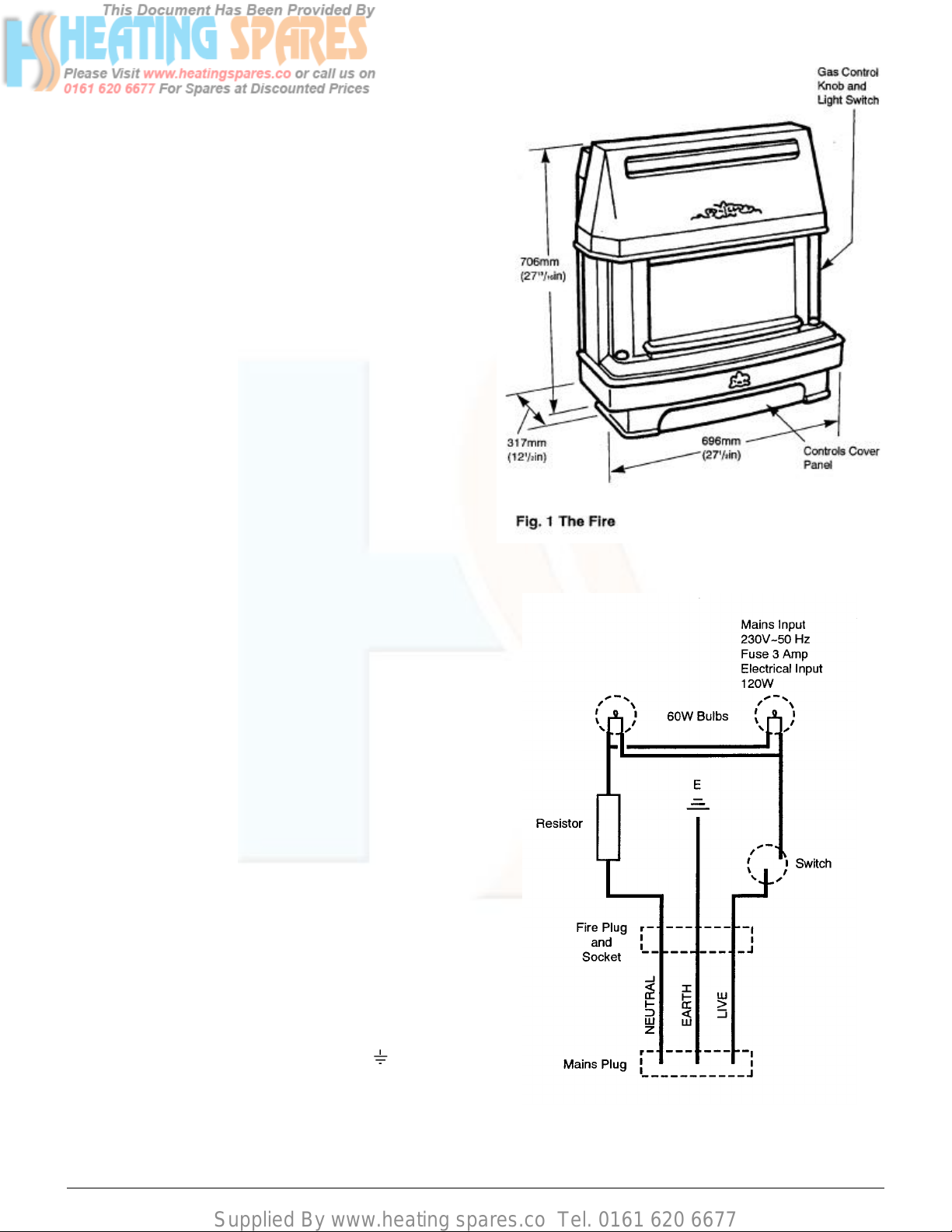
Dimensions
HEIGHT
WIDTH
DEPTH
Projection in room
706mm (27 13/
696mm (27 ½ in)
317mm (12 ½ in)
16
in)
INPUT
OUTPUT
SETTING PRESSURE
(COLD)
GAS
ELECTRICAL
(MAIN INPUT)
RESISTOR
BURNER
PILOT IGNITION
WEIGHT
HEIGHT FROM HEARTH TO
TOP OF FLUE SPIGOT
TAP
BURNER INJECTORS
High - 5.42kW (18,500 Btu/h)
Low - 2.10kW (7,200 Btu/h)
High - 3.47kW (11,840 Btu/h)
12.5 mbar ± 1.0 mbar
5.0 in w.g. ± 0.4in w.g.
Natural Gas
230 volts ~ 50 Hz - 3A - 120W
68 ohms
Aerated - Duplex
Piezo Unit - Spark Gap
2.5mm - 4.0mm
40kg (88 Ibs)
489mm (19 ¼ in)
Duplex with rotary piezo and
flame failure device operated
by Oxy-pilot
230
ELECTRICAL CONNECTION
THIS APPLIANCE MUST BE EARTHED
ALL EXTERNAL WIRING BETWEEN THE APPLIANCE AND
THE ELECTRICAL SUPPLY SHALL COMPLY WITH
CURRENT I.E.E. REGULATIONS. The mains lead has the
billowing specifications: 16/0.2mm - 3 core PVC covered PVC insulated wire to BS 6500.
IMPORTANT: Mains lead wires:
Green and yellow – Earth
Blue – Neutral
Brown – Live
FOR THE MAINS PLUG USE A 3AMP FUSE. The appliance
is supplied with approximately 3 metres of wire and a mains
plug. A longer cable may be fitted as follows:
(a) Remove the socket and plug from the cable supplied.
(b) Re-assemble on the longer cable ensuring both socket
and plug are wired correctly.
If a different mains plug is used from the one supplied with
appliance proceed as follows:
The wire which is coloured green and yellow must be
connected to the terminal in the plug which is marked
by the letter E’ or by the earth symbol or coloured
green or green and yellow. The wire which is coloured
blue must be connected to the terminal which is
marked with the letter ‘N’ or coloured black. The wire
which is coloured brown must be connected to the
terminal which is marked with the letter ‘L’ or coloured
red.
 Loading...