

Page 1

IT
RUS
FR
ENG
Page 2

PER L’INSTALLATORE
INDICE
1 DESCRIZIONE DELL’APPARECCHIO . . . . . . . . . . . . . . . . . . . . . . . . . . . . . . . . . . . . . . . . . . . . . . . . . . . . . . . . . . . . pag. 3
2 INSTALLAZIONE . . . . . . . . . . . . . . . . . . . . . . . . . . . . . . . . . . . . . . . . . . . . . . . . . . . . . . . . . . . . . . . . . . . . . . . . . . . . . . pag. 4
3 CARATTERISTICHE . . . . . . . . . . . . . . . . . . . . . . . . . . . . . . . . . . . . . . . . . . . . . . . . . . . . . . . . . . . . . . . . . . . . . . . . . . . . pag. 8
4 USO E MANUTENZIONE . . . . . . . . . . . . . . . . . . . . . . . . . . . . . . . . . . . . . . . . . . . . . . . . . . . . . . . . . . . . . . . . . . . . . . pag. 10
IMPORTANTE
Al momento di effettuare la prima accensione dell’apparecchio è buona norma procedere ai
seguenti controlli:
– Controllare che non vi siano liquidi o materiali infiammabili nelle immediate vicinanze della
caldaia.
– Accertarsi che il collegamento elettrico sia stato effettuato in modo corretto e che il filo di
terra sia collegato ad un buon impianto di terra.
– Aprire il rubinetto del gas e verificare la tenuta degli attacchi compreso quello del brucia-
tore.
– Accertarsi che la caldaia sia predisposta al funzionamento per il tipo di gas erogato.
– Verificare che il condotto di evacuazione dei prodotti della combustione sia libero.
– Verificare che le eventuali saracinesche siano aperte.
– Assicurarsi che l'impianto sia stato caricato d'acqua e risulti ben sfiatato.
–
Sfiatare l’aria esistente nelle tubazioni gas agendo sull’apposito sfiatino presa pressione posto
all’entrata della valvola gas.
SLIM HPS - ITALIANO
Page 3
1.1 INTRODUZIONE
Le “Slim HPS” sono dei generatori ad acqua calda adatti per impianti di riscaldamento di media potenzialità. Sono complete di
tutti gli organi di sicurezza e di controllo previsti dalle Norme UNI-CIG ed in linea con i
dettami delle direttive europee
2009/142/CEE, 2004/108/CEE,
2006/95/CEE e 92/42/CEE. Possono
essere alimentate a gas naturale (metano)
e a gas butano (G30) o propano (G31).
Attenersi alle istruzioni riportate in questo
manuale per una corretta installazione e un
perfetto funzionamento dell’apparecchio.
3
IT
RUS
FR
ENG
1 DESCRIZIONE DELL’ APPARECCHIO
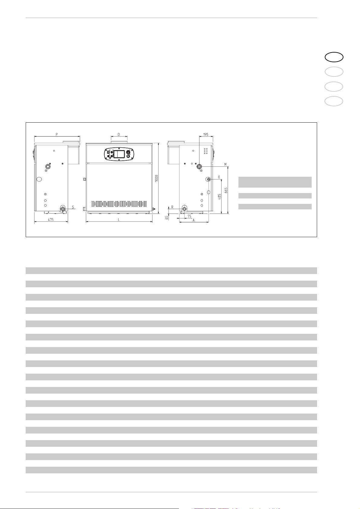
1.2 DIMENSIONI
Fig. 1
R Ritorno impianto 1
1
/2”
M Mandata impianto 11/2”
G Alimentazione gas 1”
S Scarico caldaia 3/4”
LDPA
mm ø mm mm mm
1.80 940 180 645 415
1.99 1140 225 645 415
1.110 1240 250 670 400
1.3 DATI TECNICI
Slim HPS 1.80 1.99 1.110
Potenza termica kW 56,0-78,7 69,9-98,6 74,7-107,9
Portata termica kW 62,2-87,4 77,7-109,5 85,5-120,5
Elementi di ghisa n° 9 11 12
Potenza elettrica assorbita W16 16 69
Pressione max esercizio bar 4 4 4
Pressione di collaudo bar 6 6 6
Contenuto acqua l28 34 37
Categoria II2H3+ II2H3+ II2H3+
Tipo B11BS B11BS B11
Temperatura fumi °C 160 144 140
Portata fumi kg/h 180 287 330
Temperatura max esercizio °C 95 95 95
Campo regolazione riscaldamento °C 40÷85 40÷85 40÷85
Ugelli gas principale
Quantità n° 8 10 11
Metano ø mm 2,95 2,95 2,95
G30 - G31 ø mm 1,70 1,70 1,70
Portata gas*
Metano m3st/h 9,2 11,6 12,7
Butano (G30) kg/h 6,8 8,5 9,3
Propano (G31) kg/h 6,7 8,3 9,1
Pressione gas bruciatori
Metano mbar 4,6 - 9,1 4,7 - 9,3 4,6-9,3
Butano (G30) mbar 12,3 - 25,4 12,5 - 25,1 12,6-25,6
Propano (G31) mbar 16,1 - 30,2 16,6 - 32,7 16,6-34,3
Pressione alimentazione gas
Metano mbar 20 20 20
Butano (G30) mbar 30 30 30
Propano (G31) mbar 37 37 37
Peso kg 266 322 350
* Le portate gas sono riferite al potere calorifico inferiore in condizioni standard a 15°C - 1013 mbar.
Page 4
L'installazione deve intendersi fissa e dovrà
essere effettuata esclusivamente da ditte
specializzate e qualificate, secondo quanto
prescrive la Legge 46/90, ottemperando a
tutte le istruzioni e disposizioni riportate in
questo manuale.
Si dovranno inoltre osservare tutte le disposizioni dei Vigili del Fuoco, quelle dell’Azienda
del Gas, quanto richiamato dalla Legge
10/91 relativamente ai Regolamenti
Comunali e dal DPR 412/93.
2.1 LOCALE CALDAIA
Le caldaie “Slim HPS”, di potenzialità superiore ai 35 kW, devono disporre di un locale
tecnico con caratteristiche dimensionali e
requisiti in conformità al DM 12/04/96 n.
74 “Approvazione della regola tecnica di prevenzione incendi per la progettazione, la
costruzione e l’esercizio degli impianti termici alimentati da combustibili gassosi”.
L’altezza minima del locale caldaia deve corrispondere a quella indicata in fig. 3, in funzione della portata termica complessiva. La
distanza minima fra le pareti del locale e i
punti esterni della caldaia (lato dx, sx, poste-
riore) non deve risultare inferiore a 0,60 m.
È consentito che più apparecchi siano posti
tra loro in adiacenza, a condizione che tutti i
dispositivi di sicurezza e di controllo siano
facilmente raggiungibili. è inoltre necessario, per l'afflusso dell'aria al locale, realizzare
sulle pareti esterne delle aperture di aerazione la cui superficie, calcolata secondo
quanto impartito nel punto 4.1.2 dello stesso DM, non deve essere in ogni caso inferiore di 3.000 cm2e nel caso di gas di densità maggiore di 0,8 a 5.000 cm2.
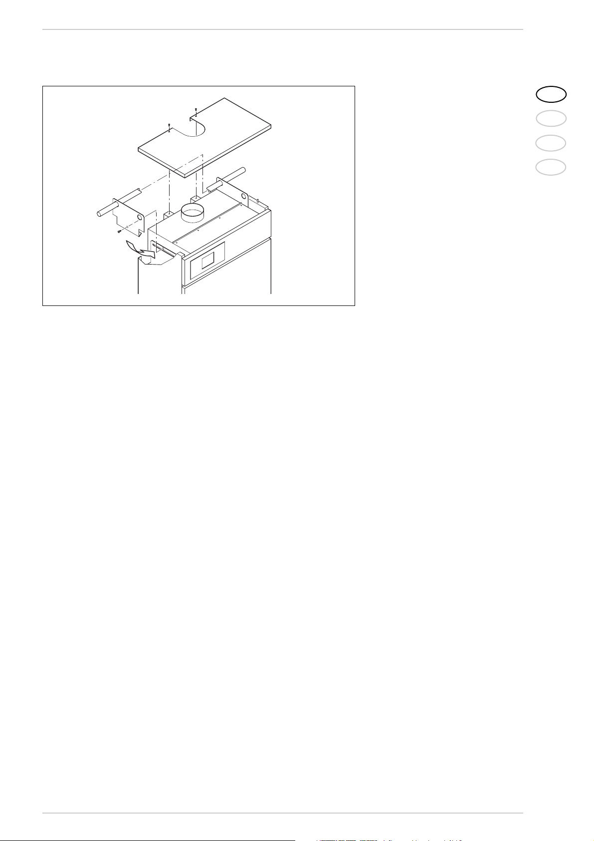
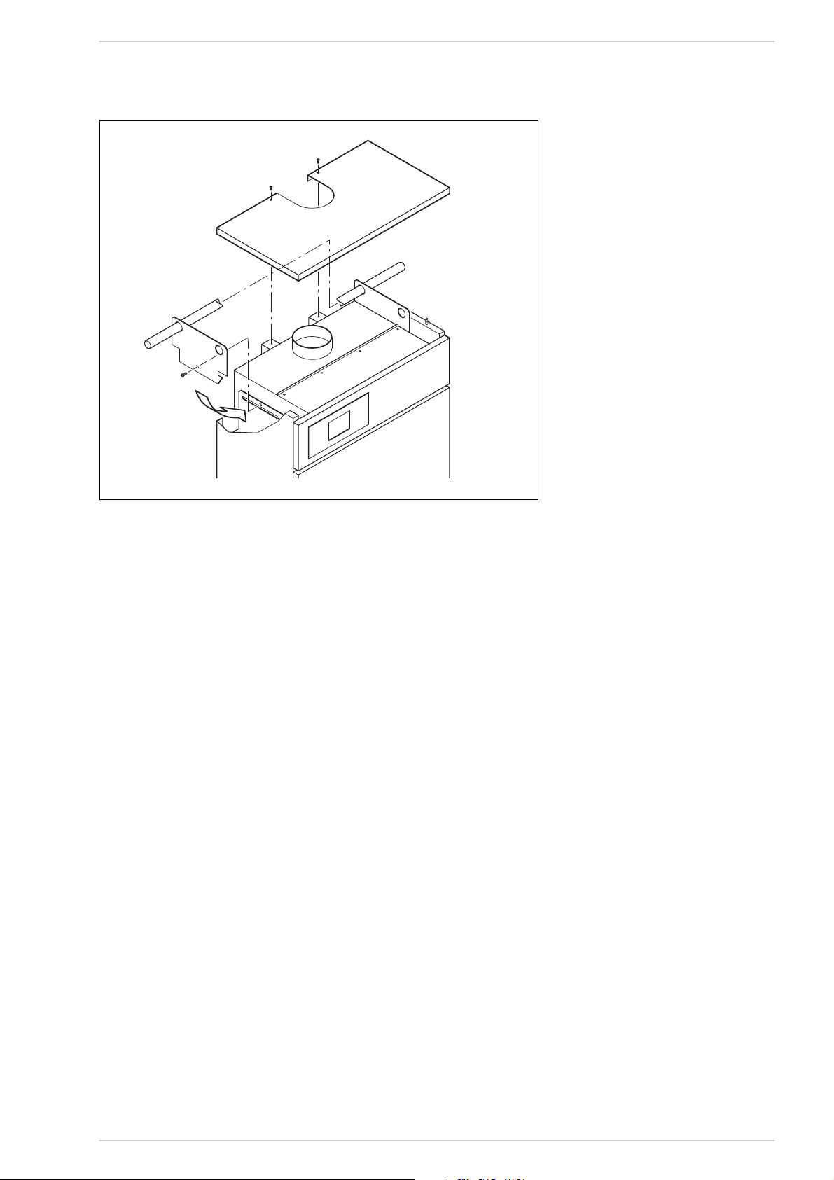
2.1.1 Movimentazione
Una volta inserita la caldaia nell’apposito
locale, tolto l’imballo, la movimentazione si
effettua procedendo come segue (fig. 3/a):
– rimuovere il coperchio mantello;
– agganciare le due staffe di sollevamento
(poste sulla parte posteriore della caldaia) bloccandole con le viti a corredo;
– inserire due tubi 3/4” nei fori previsti
sulle staffe, sollevare con cautela la caldaia ed effettuare la movimentazione.
4
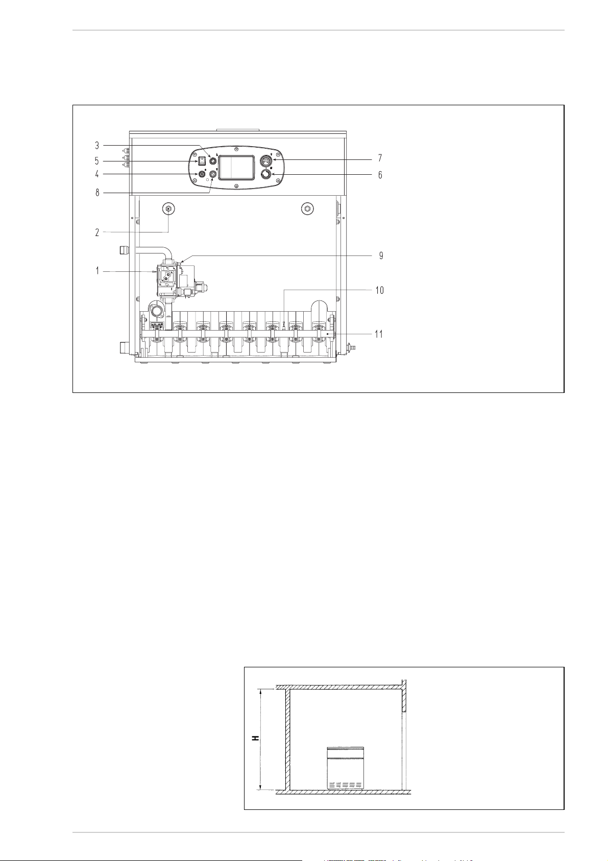
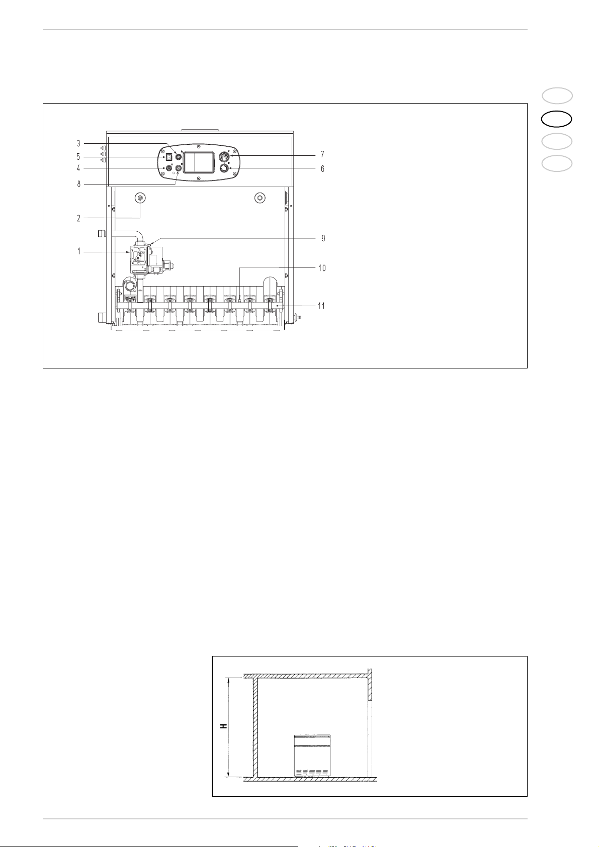
1.4 COMPONENTI PRINCIPALI
Fig. 2
LEGENDA
1 Valvola gas
2 Guaina 1/2”
3 Termostato sicurezza
4 Sblocco apparecchiatura
5 Interruttore generale
6 Termostato regolazione a gradino
7 Termometro
8 Dispositivo sicurezza fumi
9 Presa pressione 1/8” (vers. “1.110”)
10 Presa pressione 1/8”
11 Collettore bruciatori
2 INSTALLAZIONE
Fig. 3
H in funzione della portata
termica complessiva:
– non superiore a 116 kW: 2,00 m
– superiore a 116 kW
fino a 350 kW: 2,30 m
– superiore a 350 kW fino a
580 kW: 2,60 m
– superiore a 580 kW: 2,90 m
Page 5
2.2 ALLACCIAMENTO IMPIANTO
Prima di procedere al collegamento della
caldaia è buona norma far circolare acqua
nelle tubazioni per eliminare gli eventuali
corpi estranei che potrebbero compromettere la buona funzionalità dell’apparecchio.
L'allacciamento all'impianto deve essere
eseguito con raccordi rigidi che non devono
provocare sollecitazioni di alcun genere all'apparecchio. È opportuno che i collegamenti siano facilmente disconnettibili a mezzo bocchettoni con raccordi girevoli. È sempre consigliabile montare delle idonee saracinesche di intercettazione sulle tubazioni di
mandata e di ritorno impianto.
Per poter ottenere una buona distribuzione d'acqua all'interno del corpo in ghisa è
necessario che le tubazioni di mandata e
ritorno impianto siano collegate sullo
stesso lato della caldaia. Di serie la caldaia viene fornita con gli attacchi sul lato
sinistro, con la possibilità che gli stessi
possano essere portati sul lato destro. In
tal caso spostare sullo stesso lato sia il distributore d'acqua, posto sul collettore di
ritorno, che i bulbi dei termostati posti
nella guaina.
È consigliabile che il salto termico tra la tubazione di mandata e ritorno impianto non
superi i 20°C. È pertanto utile a tale scopo
installare una valvola miscelatrice.
ATTENZIONE: È necessario che la pompa o
più pompe di circolazione dell’impianto siano inserite contemporaneamente all'accensione della caldaia.
A tale proposito è consigliato l'uso di un sistema automatico di precedenza.
L'allacciamento gas deve essere realizzato
con tubi di acciaio senza saldatura (tipo
Mannesmann), zincati e con giunzioni filettate e guarnite, escludendo raccordi a tre
pezzi salvo per i collegamenti iniziali e finali.
Negli attraversamenti dei muri la tubazione
deve essere posta in apposita guaina. Nel
dimensionamento delle tubazioni gas, da
contatore a caldaia, si dovrà tenere conto
sia delle portate in volumi (consumi) in
m3/h che della relativa densità del gas
preso in esame.
Le sezioni delle tubazioni costituenti l’impianto devono essere tali da garantire una
fornitura di gas sufficiente a coprire la massima richiesta, limitando la perdita di pressione tra contatore e qualsiasi apparecchio
di utilizzazione non maggiore di:
– 1,0 mbar per i gas della seconda fami-
glia (gas naturale)
– 2,0 mbar per i gas della terza famiglia
(butano o propano).
All’interno del mantello é applicata una targhetta adesiva sulla quale sono riportati i
dati tecnici di identificazione e il tipo di gas
per il quale la caldaia é predisposta.
2.3 CARATTERISTICHE
ACQUA DI ALIMENTAZIONE
L’acqua di alimentazione del circuito riscaldamento deve essere trattata in conformità alla Norma UNI-CTI 8065.
È opportuno ricordare che anche piccole
incrostazioni di qualche millimetro di spessore provocano, a causa della loro bassa
conduttività termica, un notevole surriscaldamento delle pareti della caldaia, con conseguenti gravi inconvenienti.
È assolutamente indispensabile il trattamento dell'acqua nei seguenti casi:
– Impianti molto estesi (con elevati conte-
nuti d'acqua).
– Frequenti immissioni d'acqua di reinte-
gro nell'impianto.
– Nel caso si rendesse necessario lo svuo-
tamento parziale o totale dell'impianto.
2.3.1 Filtro sulla tubazione gas
La valvola gas monta di serie un filtro all'in-
gresso che non è comunque in grado di trattenere tutte le impurità contenute nel gas e
nelle tubazioni di rete. Per evitare il cattivo
funzionamento della valvola, o in certi casi
addirittura l'esclusione delle sicurezze di cui
la stessa è dotata, si consiglia di montare all'entrata della tubazione gas della caldaia un
adeguato filtro.
2.4 RIEMPIMENTO IMPIANTO
Il riempimento va eseguito lentamente per
dare modo alle bolle d'aria di uscire attraverso gli opportuni sfoghi posti sull'impianto
di riscaldamento.
La pressione di caricamento a freddo dell'impianto e la pressione di pregonfiaggio del
vaso di espansione, dovranno corrispondere o comunque non essere inferiori all'altezza della colonna statica dell'impianto (Esempio: per una colonna statica di 5 metri la
pressione di precarica del vaso e la pressione di caricamento dell'impianto dovranno
corrispondere almeno al valore minimo di
0,5 bar).
2.5 CANNA FUMARIA
Una canna fumaria per l’evacuazione nell’atmosfera dei prodotti della combustione di
apparecchi a tiraggio naturale deve rispondere ai seguenti requisiti:
– essere a tenuta dei prodotti della com-
bustione, impermeabile e termicamente
isolata;
– essere realizzata in materiali adatti a
resistere nel tempo alle normali sollecitazioni meccaniche, al calore ed all’azione dei prodotti della combustione e delle
loro eventuali condense;
– avere andamento verticale ed essere
priva di qualsiasi strozzatura in tutta la
sua lunghezza;
– essere adeguatamente coibentata per
evitare fenomeni di condensa o di raffreddamento dei fumi, in particolare se
posta all’esterno dell’edificio od in locali
non riscaldati;
– essere adeguatamente distanziata
mediante intercapedine d’aria o isolanti
opportuni, da materiali combustibili e
facilmente infiammabili;
– avere al di sotto dell’imbocco del primo
canale da fumo una camera di raccolta
di materiali solidi ed eventuali condense,
di altezza pari almeno a 500 mm.
L’accesso a detta camera deve essere
garantito mediante un’apertura munita
di sportello metallico di chiusura a tenuta d’aria;
– avere sezione interna di forma circolare,
quadrata o rettangolare: in questi ultimi
due casi gli angoli devono essere arrotondati con raggio non inferiore a 20
mm; sono ammesse tuttavia anche
sezioni idraulicamente equivalenti;
– essere dotata alla sommità di un comi-
gnolo, il cui sbocco deve essere al di
fuori della cosiddetta zona di reflusso al
5
IT
RUS
FR
ENG
Fig. 3/a
Page 6
fine di evitare la formazione di contropressioni, che impediscano il libero scarico nell’atmosfera dei prodotti della
combustione. è necessario quindi che
vengano rispettate le altezze minime
indicate in fig. 4;
– essere priva di mezzi meccanici di aspi-
razione posti alla sommità del condotto;
– in un camino che passa entro od è
addossato a locali abitati non deve esistere alcuna sovrappressione.
2.5.1 Dimensionamento
canna fumaria
Il corretto dimensionamento della canna
fumaria è condizione essenziale per il buon
funzionamento della caldaia.
Per calcolare la sezione utile della canna
fumaria è necessario fare riferimento alla
norma UNI 9615-90.
I fattori principali da considerare per il calcolo della sezione sono: la portata termica
della caldaia, il tipo di combustibile, il valore
in percentuale di CO2, la portata in massa
dei fumi al carico nominale, la temperatura
fumi, la rugosità della parete interna, l’effetto della gravità sulla pressione di tiraggio
che dovrà tenere conto della temperatura
esterna e dell’altitudine.
2.6 ALLACCIAMENTO
ELETTRICO
La caldaia è fornita con cavo elettrico di alimentazione. L’alimentazione dovrà essere
effettuata con tensione monofase 230V 50Hz attraverso un interruttore generale
protetto da fusibili con distanza tra i contatti di almeno 3 mm. Il termostato ambiente
da utilizzare deve essere solamente di classe II in conformità alla norma EN 60730.1
(contatto elettrico pulito).
NOTA:
L’apparecchio deve essere collegato a un
efficace impianto di messa a terra. La
BAXI declina qualsiasi responsabilità per
danni a persone o cose derivanti dalla
mancata messa a terra della caldaia.
Prima di effettuare qualsiasi operazione
sul quadro elettrico disinserire l’alimentazione elettrica.
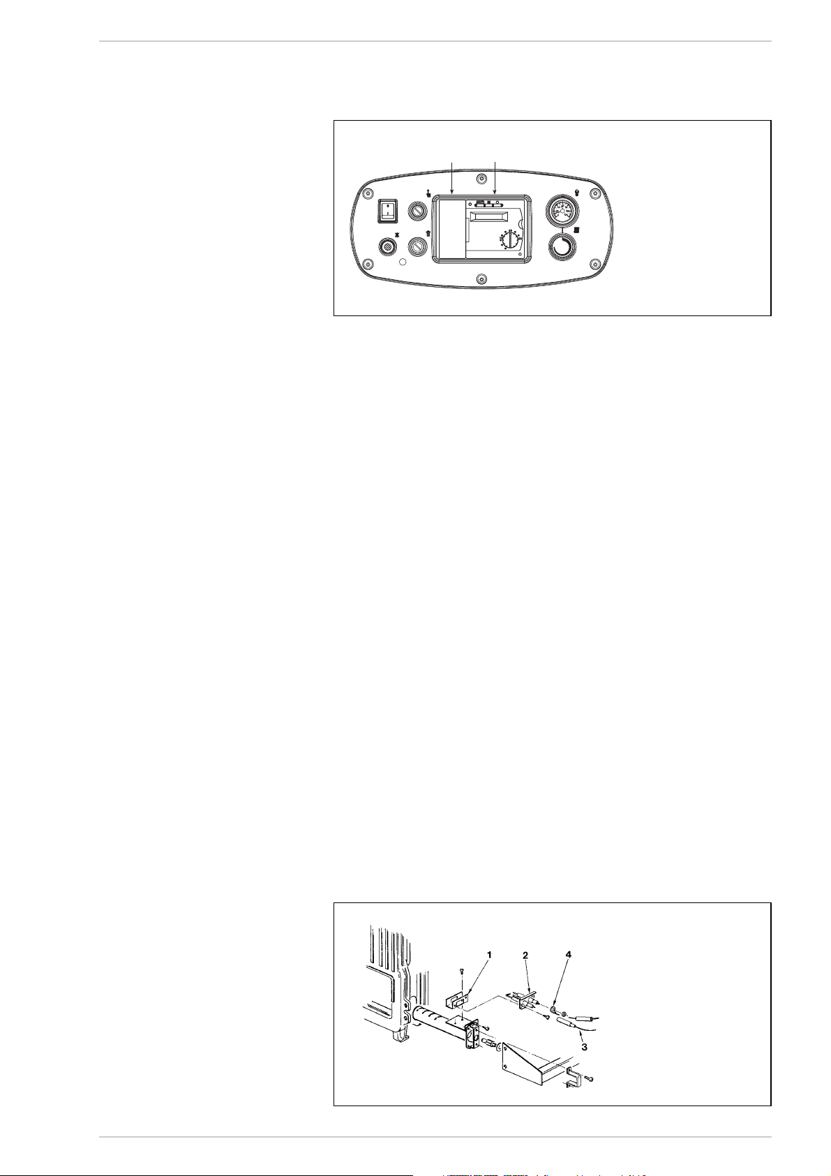
2.6.1 Collegamento elettrico
RVA43.222 (optional)
Nel circuito elettrico è prevista una serie di
connettori per l’installazione di una centralina optional, contrassegnati da diversi colori: nero, rosso e marrone (fig. 5).
I connettori sono polarizzati cosicchè non è
possibile invertirne l’ordine.
Per installare la centralina è necessario
collegare tali connettori e rimuovere dalla
morsettiera i ponti 4-5 e 11-12 (contrassegnati in grassetto nello schema di fig. 6).
La centralina consente inoltre l’utilizzo di
sonde e unità ambiente i cui connettori,
polarizzati e colorati, si trovano in un sacchetto all’interno del quadro comandi.
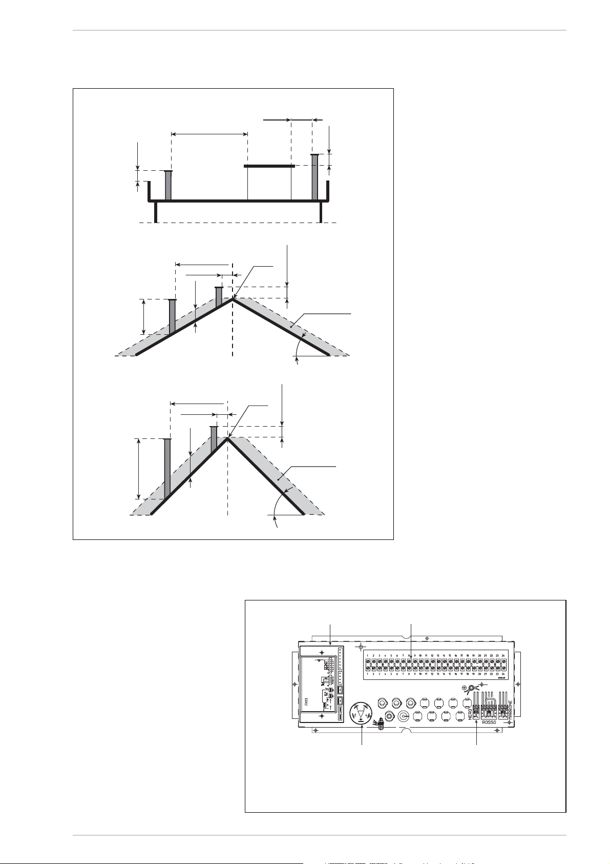
6
Tetto piano
Fig. 4
Fig. 5
LEGENDA
1 Filtro antidisturbo
2 Connettori centralina
(nero/rosso/marrone)
3 Apparecchiatura
4 Morsettiera
0,50 m
Tetto a 30 °
1,20 m min.
Tetto a 45°
> 5 m
> 1,30 m
≤ 1,30 m
0,80 m
Volume
tecnico
Colmo
≤ 5 m
0,50 m
oltre il colmo
30°
0,50 m
Zona di reflusso
> 1,50 m
≤ 1,50 m
1,50 m
2 m min.
Colmo
0,50 m
oltre il colmo
Zona di reflusso
45°
3 4
1
2
Page 7
7
IT
RUS
FR
ENG
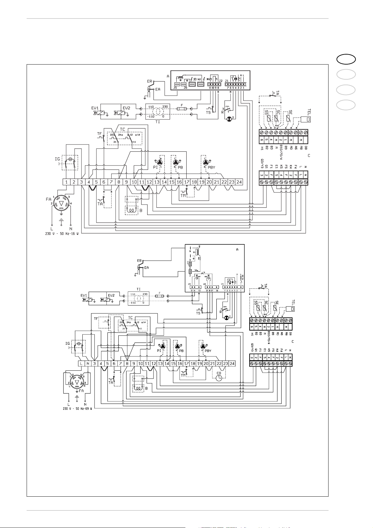
2.6.2 Schema elettrico
vers. “1.80 - 1.99”
vers. “1.110”
CODICI RICAMBI
CONNETTORI:
J1 cod. 6278669
J2 cod. 6278670
CODICI RICAMBI
CONNETTORI:
J1 cod. 6293511
J3 cod. 6293512
J4 cod. 6293510
Fig. 6
LEGENDA
IG Interruttore generale
TC Termostato reg. a gradino
EA Elettrodo accensione
EV2 Bobina valvola gas
EV1 Bobina valvola gas
TA Termostato ambiente
R Sblocco apparecchiatura
B Gruppo bobina
ER Elettrodo rivelazione
TS Termostato sicurezza
A Apparecchiatura
TF Dispositivo sicurezza fumi
FA Filtro antidisturbo
PI Pompa impianto (non di fornitura)
PB Pompa bollitore (non di fornitura)
TEL Unità ambiente QAA70 (optional)
SE Sonda temperatura esterna (optional)
SC Sonda immersione caldaia QAZ21 (optional)
SS Sonda immersione bollitore QAZ21 (optional)
C Connettori centralina RVA 43.222
(nero - rosso - marrone)
F Fusibile (T 200mA)
PBY Pompa di ricircolo
TI Trasformatore d’isolamento
(solo per FR/NL)
TM Termostato di temperatura minima
NOTA:
Quando non si utilizza la centralina per collegare il TA togliere il ponte tra i morsetti 6-7.
Collegando la centralina rimuovere i ponti 45 e 11-12. Effettuare il collegamento delle
pompe (PB-PI) come riporta lo schema solo
nel caso si utilizzi la centralina RVA 43.222.
Page 8
3.1 APPARECCHIATURA
ELETTRONICA
La “Slim HPS” ad accensione automatica
(senza fiamma pilota) dispone di una apparecchiatura elettronica di comando e protezione tipo FM 11 o DTM 12, con trasformatore incorporato, posta all’interno della scatola di protezione del pannello strumentato.
L'accensione e rivelazione di fiamma è controllata da un gruppo elettrodi posto sul
bruciatore in grado di garantire la massima
sicurezza, con tempi di intervento per spegnimenti accidentali o mancanza gas,
rispettivamente di 8 e 4 secondi (fig. 8).
8
3 CARATTERISTICHE
Fig. 8
LEGENDA
1 Supporto elettrodi
2 Gruppo elettrodi
3 Cavo elettrodo accensione
4 Cavo elettrodo rivelazione
2.7 CENTRALINA RVA43.222
(optional)
Tutte le funzioni della caldaia possono essere gestite dalla centralina cod. 8096303,
fornita con sonda temperatura esterna
(SE) e sonda immersione caldaia (SC) (fig.
7). La centralina prevede il collegamento di
una ulteriore serie di connettori a bassa
tensione per il collegamento delle sonde e
dell’unità ambiente (i connettori si trovano
in un sacchetto all’interno del quadro
comandi). Il bulbo della sonda dell’eventuale
bollitore esterno (SS), optional cod.
6277110, deve essere inserito nella guaina
del bollitore e quello della sonda caldaia
(SC) nella guaina di caldaia.
Per il montaggio della sonda temperatura
esterna (SE) seguire le istruzioni riportate
nell’imballo della sonda stessa.
Per effettuare i collegamenti elettrici fare
riferimento allo schema di fig. 6.
ATTENZIONE: Per garantire il corretto
funzionamento della cantrale porre il termostato di regolazione della caldaia al
massimo.
2.7.1 Caratteristiche e funzioni
“RVA43” è realizzato come regolatore di
singola caldaia mono e bi-stadio o come
regolatore di cascata per gestire fino a
sedici caldaie.
Economia di esercizio
–
Abilitazione o non della produzione calore
in presenza di integrazione con accumulo.
– Gestione climatica della temperatura di
caldaia con possibilità di compensazione
ambiente.
– Gestione di un circuito di riscaldamento
diretto (con pompa) per ogni regolatore.
– Funzione di autoadattamento della curva
climatica in base all’inerzia termica dell’edificio ed alla presenza di “calore gratuito” (con compensazione ambiente).
– Funzione di ottimizzazione all’accensione
ed allo spegnimento (riscaldamento
accellerato e prespegnimento).
– Funzione di economia giornaliera calcola-
to sulla base delle caratteristiche dinamiche delle strutture.
–
Commutazione estate/inverno automatica
.
Funzioni di protezione
– Temperatura minima e massima di man-
data tarabili.
– Protezione antigelo differenziata di cal-
daia, accumulo acqua calda sanitaria ed
impianto.
– Protezione al surriscaldamento della cal-
daia.
– Protezione antigrippaggio delle pompe.
– Protezione del bruciatore con tempo
minimo di funzionamento.
Funzioni operative
– Messa in funzione semplificata.
– Tutte le tarature sono effettuabili sul
regolatore.
– Standard per la programmazione setti-
manale.
– Tutte le tarature e regimi di funziona-
mento riscontrabili tramite display e leds
luminosi.
– Test dei relais e delle sonde.
Produzione acqua sanitaria
– Programmazione orari giornalieri.
– Possibilità di impostare la temperatura
minima di consegna acqua calda sanitaria per il periodo di riduzione.
– Possibilità comando pompa di carico
accumulo.
–
Priorità del circuito sanitario selezionabile.
Altre caratteristiche tecniche
– Facile connessione con un’unità ambien-
te di tipo digitale (QAA70).
Fig. 7
LEGENDA
1 Copriforo in plastica
2 Centralina (optional)
1
2
Page 9
3.1.1 Ciclo di funzionamento
Prima di accendere la caldaia accertarsi
con un voltmetro che il collegamento elettrico alla morsettiera sia stato fatto in modo
corretto rispettando le posizioni di fase e
neutro come previsto dallo schema.
Premere l'interruttore generale posto sul
quadro comandi rilevando presenza di tensione con l'accensione della lampada spia.
La caldaia a questo punto si metterà in funzione inviando, attraverso il programmatore, una corrente di scarica sull'elettrodo di
accensione ed aprendo contemporaneamente la valvola gas.
L'accensione del bruciatore normalmente si
ha nel tempo di 2 o 3 secondi.
Si potranno comunque manifestare mancate accensioni con conseguente attivazione
del segnale di blocco dell'apparecchiatura
che possiamo così riassumere:
– Mancanza di gas
L'apparecchiatura effettua regolarmente il ciclo inviando tensione sull'elettrodo
di accensione che persiste nella scarica
per 8 o 4 sec. max, non verificandosi
l'accensione del bruciatore l’apparecchiatura va in blocco.
Si può manifestare alla prima accensione o dopo lunghi periodi di inattività con
presenza d'aria nella tubazione. Può essere causata dal rubinetto gas chiuso o
da una delle bobine della valvola che presenta l'avvolgimento interrotto non consentendone l'apertura.
– L'elettrodo di accensione non emette
la scarica
Nella caldaia si nota solamente l'apertura del gas al bruciatore, trascorsi 8 o 4
sec. l'apparecchiatura va in blocco.
Può essere causato dal cavo dell'elettrodo che risulta interrotto o non è ben fissato al morsetto dell’apparecchiatura;
oppure l'apparecchiatura ha il trasformatore bruciato.
– Non c'è rivelazione di fiamma
Dal momento dell'accensione si nota la
scarica continua dell'elettrodo nonostante il bruciatore risulti acceso. Trascorsi 8 o 4 sec. cessa la scarica, si spegne il bruciatore e si accende la spia di
blocco dell'apparecchiatura.
Si manifesta nel caso in cui non è stata
rispettata la posizione di fase e neutro
sulla morsettiera. Il cavo dell'elettrodo di
rivelazione è interrotto o l'elettrodo stesso è a massa; l'elettrodo è fortemente
usurato, necessita sostituirlo.
L’apparecchiatura è difettosa.
Per mancanza improvvisa di tensione si ha
l'arresto immediato del bruciatore, al ripristino della tensione la caldaia si rimetterà
automaticamente in funzione.
3.1.2 Circuito di ionizzazione
Il controllo del circuito di ionizzazione si effettua con un microamperometro del tipo a
quadrante o meglio ancora se di tipo a lettura digitale con scala da 0 a 50 µA. I terminali del microamperometro dovranno essere collegati elettricamente in serie al cavo
dell'elettrodo di rivelazione. In funzionamento normale il valore oscilla intorno ai 6÷10
µA. Il valore minimo di corrente di ionizzazione per il quale l'apparecchiatura può entrare in blocco oscilla intorno ai 1 µA. In tal caso, occorrerà accertarsi che vi sia un buon
contatto elettrico e verificare il grado di usura dell'elettrodo di rilevazione.
3.2 TERMOSTATO REGOLAZIONE
A GRADINO
La caldaia è fornita con termostato di regolazione a doppio contatto di scambio a taratura differenziata (6 fig. 2) che consente di
ottenere, prima dello spegnimento totale
del bruciatore, una riduzione di potenza
attraverso il gruppo bobina montato sul
regolatore della valvola gas. Questo sistema di modulazione a gradino permette di
ottenere i seguenti vantaggi:
– Un più elevato rendimento globale della
caldaia.
– Contenere entro valori accettabili l'au-
mento di temperatura che si manifesta
nel corpo ghisa (inerzia termica) allo
spegnimento del bruciatore.
3.3 DISPOSITIVO
SICUREZZA FUMI
È una sicurezza contro il reflusso dei fumi in
ambiente per inefficienza od otturazione parziale della canna fumaria (8 fig. 2).
Interviene bloccando il funzionamento della
valvola gas quando il rigetto dei fumi in
ambiente è continuo, e in quantità tali da renderlo pericoloso.
Per poter consentire la ripartenza della caldaia sarà necessario svitare la copertura del
termostato e riarmare il pulsante sottostante. Prima di effettuare questa operazione
accertarsi che sia stata tolta tensione al
quadro comando.
Qualora il dispositivo dovesse intervenire in
continuazione, sarà necessario effettuare un
attento controllo alla canna fumaria, apportando tutte le modifiche e gli accorgimenti
necessari perché possa risultare efficiente.
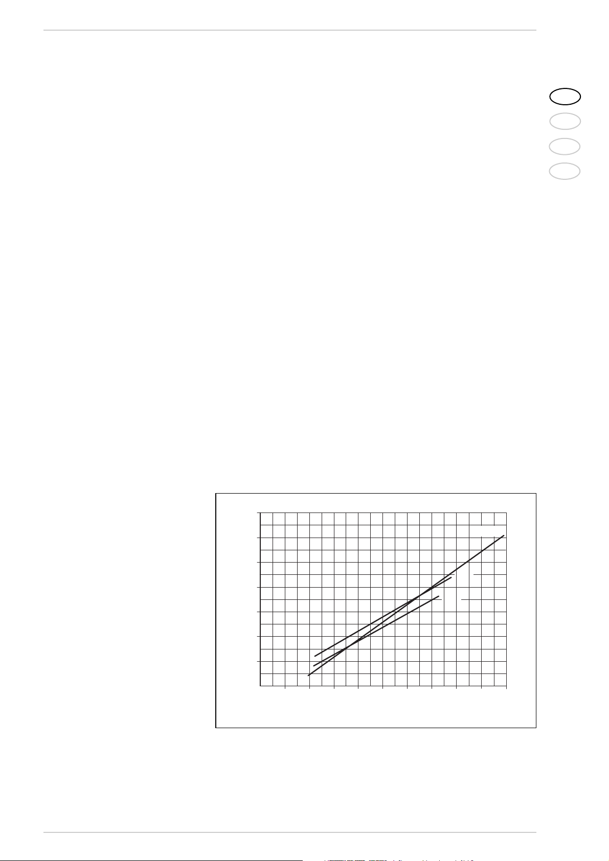
3.4 PERDITE DI CARICO
CIRCUITO CALDAIA
Le perdite di carico sono rappresentate
dal grafico di fig. 9.
9
IT
RUS
FR
ENG
Fig. 9
14 0
12 0
10 0
80
60
40
PERDITA DI CARICO (mbar)
20
1.110
1.99
1.80
0
2.000
5.000
4.0003.000
PO RTATA (l/h)
8.0007.0006.000
9.000
10.000
11.000
Page 10
10
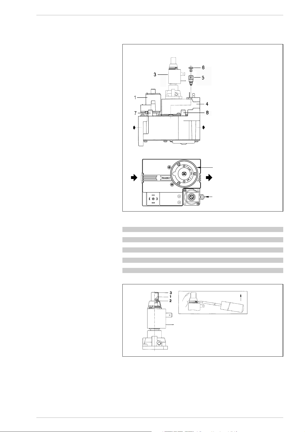
4.1 VALVOLA GAS (fig. 10)
La “Slim HPS” è prodotta di serie con valvole gas HONEYWELL VR 4605 CB (vers.
“1.80 - 1.99”) e VR 420 PB (vers. “1.110”).
Alla prima accensione della caldaia è sempre consigliabile effettuare lo spurgo della
tubazione agendo sulla presa pressione a
monte della valvola gas (7 fig. 10 - 9 fig. 2).
4.2 REGOLAZIONE VALVOLA GAS
La taratura delle pressioni di lavoro della
valvola gas viene eseguita dalla BAXI in linea
di produzione; se ne sconsiglia pertanto la
variazione. Solo in caso di passaggio da un
tipo di gas d'alimentazione (metano) ad un
altro (butano o propano) sarà consentita la
variazione delle pressioni.
Tale operazione dovrà necessariamente
essere eseguita da personale autorizzato,
pena la decadenza della garanzia.
Effettuata la variazione delle pressioni di
lavoro sigillare i regolatori.
Nel procedere alla taratura delle pressioni è
necessario seguire un ordine prestabilito
regolando prima la pressione massima e
poi la minima.
4.2.1 Regolazione pressione
massima (fig. 11)
Collegare il manometro alla presa di pressione posta sul collettore bruciatori, accendere la caldaia ed aspettare finché la pressione letta sul manometro si è stabilizzata.
Confrontare questa lettura con le pressioni
di Tabella 1.
Se é necessaria una correzione utilizzare
una chiave da 8 mm sul dado di regolazione
pressione max (1): ruotare in senso orario
per incrementare la pressione ed in senso
antiorario per diminuirla.
4.2.2 Regolazione pressione
minima (fig. 11)
Spegnere la caldaia e togliere alimentazione
alla bobina. Accendere la caldaia ed aspettare finché la pressione letta sul manometro si è stabilizzata. Confrontare questa lettura con le pressioni di Tabella 1. Se è
necessaria una correzione utilizzare un cacciavite ad intaglio per ruotare la vite di regolazione della pressione minima (2); ruotare
in senso orario per incrementare la pressione ed in senso antiorario per diminuirla.
Completate le regolazioni reinserire l’alimentazione elettrica alla bobina e rimettere
la copertura.
4.4 TRASFORMAZIONE
AD ALTRO GAS
Per effettuare la trasformazione a gas butano (G30) o propano (G31) è necessario
sostituire gli ugelli principali forniti nel kit a
richiesta, il regolatore di pressione montato
sulla valvola gas (3...20 mbar) con quello
V4336A (4...37 mbar) e, per evitare che la
caldaia vada in blocco nelle partenze a freddo, montare sulla valvola gas delle vers.
“1.80 - 1.99” l’adattatore cod. 6248303 (5
fig. 10). Per regolare la potenza riscaldamento fare riferimento al punto 4.2.
Effettuata la variazione delle pressioni di
lavoro sigillare i regolatori.
Ad operazioni ultimate applicare sul pannello del mantello l’etichetta indicante la predisposizione gas, fornita sempre a corredo
nel kit.
NOTA: Dopo il montaggio tutte le connessioni gas devono essere collaudate a tenu-
4 USO E MANUTENZIONE
LEGENDA
1 Bobina EV1
3 Regolatore di
pressione 3...20 mbar
4 Bobina EV2
5 Adattatore GPL
6 Tappo in plastica
7 Presa pressione a monte
8 Presa pressione a valle
9 Bobina EV1-EV2
Fig. 10
Slim HPS 1.80 1.99 1.110
Metano (G20)
Pressione max. bruc. mbar 9,1 9,3 9,3
Pressione min. bruc. mbar 4,6 4,7 4,6
Butano (G30)
Pressione max. bruc. mbar 25,4 25,1 25,6
Pressione min. bruc. mbar 12,3 12,5 12,6
Propano (G31)
Pressione max. bruc. mbar 30,2 32,7 34,3
Pressione min. bruc. mbar 16,1 16,6 16,6
TABELLA 1
HONEYWELL VR 4605 CB
HONEYWELL VR 420 PB
LEGENDA
1 Dado regolazione pressione max
2 Vite regolazione pressione minima
3 Copertura
Fig. 11
9
3
1
2
Page 11

ta, usando acqua saponata o appositi prodotti, evitando l’uso di fiamme libere.
La trasformazione deve essere effettuata
solo da personale autorizzato.
4.5 SMONTAGGIO MANTELLO
Per procedere allo smontaggio del mantello
eseguire le seguenti operazioni (fig. 12):
– Togliere la porta (1) del mantello fissata
con piolini a pressione.
– Per togliere il coperchio (3) svitare le
due viti che lo fissano alla camera fumo
e sollevarlo.
– Togliere il pannello anteriore superiore
(2) appoggiandolo alla camera fumo.
– Smontare il fianco sinistro (4) svitando i
dadi che lo fissano ai tiranti.
– La stessa operazione si esegue per lo
smontaggio del fianco destro (5).
– Togliere la parete interna (6) tirandola in
avanti.
– Svitare i dadi che bloccano la parete po-
steriore (7) per toglierla dai tiranti.
4.6 MANUTENZIONE
Per garantire la funzionalità e l’efficienza dell’apparecchio è necessario, nel
rispetto delle disposizioni legislative
vigenti, sottoporlo a controlli periodici;
la frequenza dei controlli dipende dalla
tipologia dell’apparecchio e dalle condizioni di installazione e d’uso.
E’ comunque opportuno far eseguire un
controllo annuale da Personale Autorizzato.
Per effettuare la pulizia del generatore
procedere nel seguente modo:
– Togliere tensione alla caldaia e chiudere
il rubinetto di alimentazione gas.
– Togliere la porta e il coperchio mantello.
– Togliere il pannello superiore della came-
ra fumo fissato alla stessa con viti auto-
filettanti.
– Togliere il gruppo gas.
– Con apposito scovolo entrare nelle file di
piolini dello scambiatore ghisa dalla par-
te superiore e, con movimento verticale,
rimuovere le incrostazioni esistenti.
– Togliere il bruciatore dal collettore porta
ugelli ed indirizzare un getto d'aria verso
l'interno dei bruciatori in modo da far
uscire l'eventuale polvere accumulatasi.
Assicurarsi che la parte superiore fora-
ta dei bruciatori sia libera da incrostazio-
ni (fig. 13).
– Togliere dal fondo della caldaia le incro-
stazioni accumulatesi e rimontare i par-
ticolari tolti controllando la posizione del-
le guarnizioni.
– Controllare il camino assicurandosi che
la canna fumaria sia pulita.
– Controllare il funzionamento delle appa-
recchiature.
– Dopo il montaggio tutte le connessioni
gas devono essere collaudate a tenuta,
usando acqua saponata o appositi pro-
dotti, evitando l’impiego di fiamme libere.
4.7 INCONVENIENTI DI
FUNZIONAMENTO
Il bruciatore principale non si accende.
– È intervenuto il dispositivo sicurezza fumi
(vedere punto 3.3).
– Controllare che arrivi tensione alla valvo-
la gas.
– Sostituire l'operatore elettrico della val-
vola.
– Sostituire la valvola.
La caldaia arriva in temperatura ma i
radiatori non si riscaldano.
– Controllare che non vi siano bolle d'aria
nell'impianto, eventualmente spurgare
dagli appositi sfoghi.
– Il regolatore climatico è regolato troppo
basso o necessita sostituirlo in quanto
difettoso.
– I collegamenti elettrici del regolatore cli-
matico non sono esatti (verificare che i
cavetti siano posti ai morsetti 6 e 7 della morsettiera caldaia).
La caldaia lavora solamente alla pressione
nominale e non effettua la riduzione di
pressione.
– Controllare se ai capi della bobina c'è
tensione.
– La bobina ha l'avvolgimento interrotto,
necessita sostituirla.
– La scheda raddrizzatrice che alimenta la
bobina è interrotta, occorre sostituirla.
– Non c'è differenziale sulla taratura dei
due contatti del termostato di regolazione, occorre sostituirlo.
–
Controllare la taratura della vite regolazione pressione minima del gruppo bobina.
La caldaia si sporca facilmente provocando
lo sfogliamento del corpo ghisa e ripetuti
interventi del termostato sicurezza fumi.
– Controllare che la fiamma del bruciatore
principale sia ben regolata e che il consumo del gas sia proporzionale alla potenza della caldaia.
– Scarsa aerazione dell'ambiente ove è in-
stallata.
–
Canna fumaria con tiraggio insufficiente
o non corrispondente ai requisiti previsti.
– La caldaia lavora a temperature troppo
basse, regolare il termostato caldaia a
temperature più elevate.
Il termostato riaccende con scarto di temperatura troppo elevato.
– Sostituire il termostato di regolazione
perché starato.
11
IT
RUS
FR
ENG
Fig. 12
LEGENDA
1 Corpo caldaia
2 Bruciatore
3 Ugello principale
4 Rondella in alluminio
5 Collettore bruciatori
Fig. 13
Page 12
12
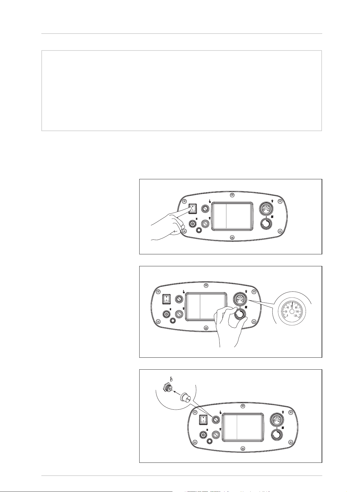
ACCENSIONE CALDAIA
Aprire il rubinetto del condotto di alimentazione gas e per effettuare l’accensione della
“Slim HPS” premere il tasto dell’interruttore generale perché la caldaia si metta a funzionare automaticamente (fig. 14).
REGOLAZIONE TEMPERATURA
La regolazione della temperatura riscaldamento si effettua agendo sulla manopola del
termostato con campo di regolazione da 40
a 85°C. Il valore di temperatura impostata
si controlla sul termometro. Per garantire
un rendimento sempre ottimale del generatore si consiglia di non scendere al di sotto
di una temperatura minima di lavoro di
60°C; si eviteranno così le possibili formazioni di condensa che possono produrre nel
tempo il deterioramento del corpo ghisa
(fig. 15).
TERMOSTATO SICUREZZA
Il termostato di sicurezza a riarmo manuale
interviene, provocando l'immediato spegnimento del bruciatore principale, quando la
temperatura in caldaia supera i 95°C.
Per poter ripristinare il funzionamento della
caldaia é necessario svitare la copertura
nera e premere il pulsantino sottostante
(fig. 16).
Se il fenomeno si verifica frequentemente
richiedere l’intervento di Personale
Tecnico Autorizzato per un controllo.
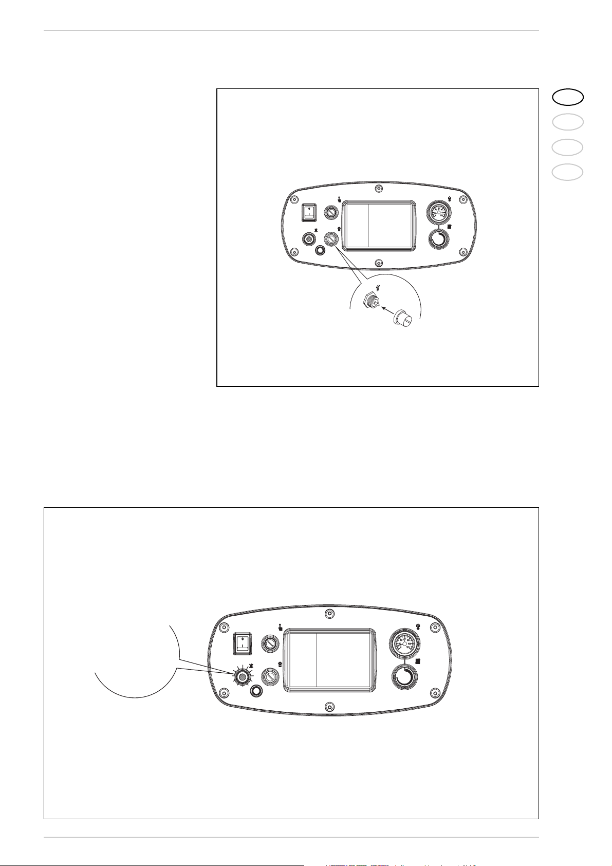
DISPOSITIVO SICUREZZA FUMI
È una sicurezza contro il reflusso dei fumi in
ambiente per inefficienza od otturazione
parziale della canna fumaria. Interviene
bloccando il funzionamento della valvola gas
quando il rigetto dei fumi in ambiente è continuo, e in quantità tali da renderlo pericoloso. Per poter ripristinare il funzionamento
AVVERTENZE
– In caso di guasto e/o cattivo funzionamento dell’apparecchio, disattivarlo, astenendosi da qualsiasi tentativo di ripa-
razione o d’intervento diretto. Rivolgersi esclusivamente a Personale Autorizzato.
– L’installazione della caldaia e qualsiasi altro intervento di assistenza e di manutenzione devono essere eseguiti da per-
sonale qualificato in conformità alle norme UNI-CIG 7129, UNI-CIG 7131 e CEI 64-8. E’ assolutamente vietato manomettere i dispositivi sigillati dal costruttore.
– E’ assolutamente vietato ostruire le griglie di aspirazione e l’apertura di aerazione del locale dove è installato l’appa-
recchio.
ACCENSIONE E FUNZIONAMENTO
Fig. 14
Fig. 15
Fig. 16
PER L’UTENTE
Page 13
13
IT
RUS
FR
ENG
della caldaia è necessario svitare la copertura del termostato e premere il pulsantino
sottostante (fig. 17).
Qualora dovesse ripertersi il blocco della
caldaia sarà necessario richiedere l’intervento di Personale Tecnico Autorizzato.
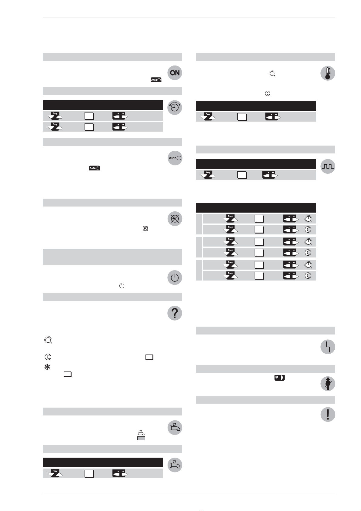
SBLOCCO APPARECCHIATURA
ELETTRONICA
Nel caso di mancata accensione del bruciatore si accenderà la spia rossa del pulsante
di sblocco. Premere il pulsante perchè la
caldaia si rimetta automaticamente in funzione (fig. 18).
Se si dovesse verificare nuovamente il
blocco della caldaia, richiedere l’intervento del Personale Tecnico Autorizzato per
un controllo.
SPEGNIMENTO CALDAIA
Per spegnere completamente la caldaia
togliere tensione premendo il tasto dell'interruttore generale (fig. 14). Nel caso di un
prolungato periodo di non utilizzo della caldaia si consiglia di togliere tensione elettrica, chiudere il rubinetto del gas e se sono
previste basse temperature, svuotare la
caldaia e l’impianto idraulico per evitare la
rottura delle tubazioni a causa del congelamento dell’acqua.
TRASFORMAZIONE AD ALTRO GAS
Nel caso si renda necessaria la trasformazio-
ne ad un gas diverso da quello per il quale la
caldaia è stata prodotta, rivolgersi esclusivamente al personale tecnico autorizzato SIME.
MANUTENZIONE
E’ opportuno programmare per tempo la
manutenzione annuale dell’apparecchio,
richiedendola a Personale Autorizzato.
Fig. 17
Fig. 18
ACCENSIONE
SPIA ROSSA
PULSANTE
DI SBLOCCO
Page 14
PER ACCENDERE IL RISCALDAMENTO
– Accendere l’interruttore di rete.
– Impostare l’ora esatta del giorno e data della settimana.
– Selezionare il modo automatico tramite il pulsante .
PER IMPOSTARE L’ORA
PER UTILIZZARE IL MODO AUTOMATICO
Nel modo automatico la temperatura del locale è regolata
in base ai periodi di riscaldamento selezionati.
– Premere il pulsante .
NOTA: Selezionare i periodi di riscaldamento a seconda
delle proprie esigenze quotidiane; in questo modo sarà
possibile ottenere un notevole risparmio energetico.
PER ATTIVARE IL RISCALDAMENTO CONTINUO
Il modo riscaldamento continuo mantiene la temperatura del
locale al livello impostato mediante la manopola di regolazione.
– Premere il pulsante “Funzionamento continuo” .
– Regolare la temperatura del locale mediante la manopo-
la di regolazione.
PER PREDISPORRE IL MODO ATTESA
(qualora l’utente sia assente per un più lungo periodo di tempo)
Il modo attesa mantiene la temperatura del locale al livello
di protezione antigelo.
– Premere il pulsante “Modo attesa” .
SIGNIFICATO DEI SIMBOLI
Sopra il display alcuni simboli indicano lo stato di funzionamento attuale. La comparsa di una barra sotto uno di questi simboli segnalerà che il corrispondente stato di funzionamento è “attivo”.
Riscaldamento alla temperatura nominale
(manopola di regolazione)
Riscaldamento alla temperatura ridotta (riga ).
Riscaldamento alla temperatura di protezione antigelo
(riga ).
NOTA: Per ulteriori informazioni sui simboli e gli stati di
funzionamento si rinvia alla documentazione dettagliata
dell’impianto di riscaldamento.
PER VARIARE LA PRODUZIONE DI ACQUA CALDA SANITARIA
La produzione di acqua calda sanitaria può essere abilitata
o disabilitata premendo un pulsante.
– Premere il pulsante “Acqua calda sanitaria” .
SE L’ACQUA SANITARIA È TROPPO CALDA O TROPPO FREDDA
SE I LOCALI SONO TROPPO CALDI O TROPPO FREDDI
– Verificare l’attuale stato di funzionamento sul display.
– In caso di temperatura nominale .
Aumentare o ridurre la temperatura del locale utilizzando
la manopola di regolazione.
– In caso di temperatura ridotta .
NOTA: Dopo ogni regolazione attendere almeno due ore
affinché la nuova temperatura si diffonda nel locale.
PER VARIARE I PERIODI DI RISCALDAMENTO
Con riferimento al giorno selezionato impostare le
variazioni come segue:
NOTE: I periodi di riscaldamento si ripetono automaticamente su base settimanale. A questo scopo selezionare il
modo automatico.
È possibile ripristinare il programma standard sulla riga
23 premendo contemporaneamente i tasti + e –.
SE IL RISCALDAMENTO NON FUNZIONA CORRETTAMENTE
– Fare riferimento alla documentazione dettagliata dell’im-
pianto di riscaldamento, seguendo le istruzioni per la soluzione dei problemi.
PER MISURARE I GAS DI COMBUSTIONE
– Premere il pulsante “spazzacamino” .
Il riscaldamento funzionerà secondo il livello richiesto.
PER RISPARMIARE ENERGIA SENZA RINUNCIARE AL COMFORT
– Nei locali abitato si consiglia una temperatura di 21°C
circa. Ogni grado in più aumenterà i costi di riscaldamento del 6-7%.
– Aerare i locali soltanto per breve tempo, aprendo com-
pletamente le finestre.
– Nei locali non occupati predisporre le valvole di regolazio-
ne in posizione antigelo.
– Lasciare libera l’area antistante i radiatori (rimuovere
mobili, tende...).
– Chiudere le imposte e le tapparelle per ridurre la disper-
sione di calore.
Selezionare Visualizzare Effettuare la regolazione
la riga tramite i pulsanti
ora del giorno
giorno della
settimana
1
2
14
15
Selezionare Visualizzare Preselezionare il blocco
la riga
settimanale o il singolo giorno
1-7 = settimana
1 = Lu/7 = Do
5
Periodo Premere Visualizzare Impostare Per
richiesto pulsante l’ora °C
Inizio
Fine
Inizio
Fine
Inizio
Fine
6
7
8
9
10
11
Selezionare Visualizzare
Correggere la temperatura
la riga mediante i pulsanti
°C
14
Periodo 1
Periodo 2
Periodo 3
13
Selezionare Visualizzare Impostare la
la riga temperatura desiderata
°C
14
CENTRALINA
Per sfruttare appieno tutte le potenzialità del regolatore “RVA 43.222” seguire le istruzioni di seguito riportate:
Page 15

ИНСТРУКЦИИ ПО УСТАНОВКЕ
ОГЛАВЛЕНИЕ
1 ОПИСАНИЕ ОБОРУДОВАНИЯ . . . . . . . . . . . . . . . . . . . . . . . . . . . . . . . . . . . . . . . . . . . . . . . . . . . . . . . . . . стр. 16
2 УСТАНОВКА . . . . . . . . . . . . . . . . . . . . . . . . . . . . . . . . . . . . . . . . . . . . . . . . . . . . . . . . . . . . . . . . . . . . . . . . . стр. 17
3 ТЕХНИЧЕСКИЕ ХАРАКТЕРИСТИКИ . . . . . . . . . . . . . . . . . . . . . . . . . . . . . . . . . . . . . . . . . . . . . . . . . . . . . стр. 21
4 ИСПОЛЬЗОВАНИЕ И УХОД . . . . . . . . . . . . . . . . . . . . . . . . . . . . . . . . . . . . . . . . . . . . . . . . . . . . . . . . . . . . стр. 23
ВАЖНО
В момент произведения первого запуска оборудования по правилу следует
провести следующие проверки:
- Убедиться в том, что в непосредственной близи от котла не находятся
жидкости и воспламеняющиеся вещества.
- Проконтролировать правильность электрического соединения и качество
устройства заземления, к которому присоединяется провод заземления.
- Открыть газ и проверить прочность соединений, включая соединение
горелки.
- Убедиться, что котел запрограммирован на работу с подаваемым типом
газа.
- Подтвердить проходимость трубы для выброса отработанных газов.
- Оставить соответствующие вентиля открытыми.
- Убедиться в том, что котел наполнен водой и оставшийся газ выведен.
- Выдуть воздух, остающийся в газовых трубах, используя штуцер газового
клапана.
SLIM HPS - РУССКИЙ
Page 16

16
1.1 ВВЕДЕНИЕ
Котлы “Slim HPS” являются генераторами
горячей воды и относятся к установкам
средней мощности. Генераторы
спроектированы в согласии с директивами
европейского союза 2009/142/CEE,
2004/108/CEE, 2006/95/CEE и 92/42/CEE.
Котлы могут работать как на природном
газе и на бутане (G 30), так и на пропане
(G 31). Для правильной установки и
отличного функционирования
оборудования следует придерживаться
инструкций, приведенных в этом
руководстве.
1 ОПИСАНИЕ ОБОРУДОВАНИЯ
1.2 РАЗМЕРЫ
Чертеж 1
R Диаметр возвратной трубы 11/2”
M
Диаметр поставляющей трубы
11/2”
G Диаметр газовой трубы 1”
S Слив бойлера 3/4”
LDPA
мм ø мм мм мм
1. 8 0 940 180 645 415
1. 9 9 1140 225 645 415
1. 110 1240 250 670 400
1.3 ТЕХНИЧЕСКИЕ ХАРАКТЕРИСТИКИ
Slim HPS 1.80 1.99 1.110
Номинальная тепловая мощность кВт 56,0-78,7 69,9-98,6 74,7-107,9
Теплоотдача кВт 62,2-87,4 77,7-109,5 85,5-120,5
Количество чугунных секций n° 9 11 12
Потребляемая энергия Вт 16 16 69
Максимальное рабочее давление Бар 4 4 4
Давление при пробных испытаниях Бар 6 6 6
Объем воды л28 34 37
Категория II2H3+ II2H3+ II2H3+
Ти п B11BS B11BS B11
Температура дыма °C 160 144 140
Выброс дыма кг/час 180 287 330
Максимальная температура °C 95 95 95
Диапазон регулировки нагрева °C 40÷85 40÷85 40÷85
Основные газовые сопла
Количество n° 8 10 11
Метан ø мм 2,95 2,95 2,95
G30 - G31 ø мм 1,70 1,70 1,70
Расход газа*
Метан м
3
/час 9,2 11,6 12,7
Бутан (G30) кг/час 6,8 8,5 9,3
Пропан (G31) кг/час 6,7 8,3 9,1
Давление газа в горелках
Метан мБар 4,6 - 9,1 4,7 - 9,3 4,6-9,3
Бутан (G30) мБар 12,3 - 25,4 12,5 - 25,1 12,6-25,6
Пропан (G31) мБар 16,1 - 30,2 16,6 - 32,7 16,6-34,3
Давление подачи газа
Метан мБар 20 20 20
Бутан (G30) мБар 30 30 30
Пропан(G31) мБар 37 37 37
Вес кг 266 322 350
* Расход газа предполагается в стандартных условиях при тепломощности 15°С-1013 мБар.
Page 17
17
IT
FR
RUS
ENG
Установка котла предполагается
стационарной и должна обязательно
осуществляться специализированной
фирмой, как это указано в законе 46/90,
следуя всем инструкциям и предписаниям
данного руководства. Кроме того следует
придерживаться предписаний пожарной
охраны и газовой инспекции, как указано
в законе 10/91 о городском регламенте и в
DPR 412/93.
2.1 КОТЕЛЬНАЯ
Котлы “Slim HPS” мощностью выше 35
кВт должны быть размещены в
техническом помещении по размерам и
характеристикам следующем норме DM
12/04/96 № 74 "Противопожарные правила
для проектирования, постройки и
использования теплового оборудования с
газовым питанием". Высота помещения
котельной должна соответствовать
приведенной на Чертеже 3, ее изменения
зависят от общей тепловой мощности
котла. Минимальное расстояние между
стенами помещения и внешними панелями
котла (правая, левая и задняя сторона) не
может быть менее 0,60 м. Разрешено
размещение нескольких аппаратов в
одном помещении при условии, что
приборы контроля и безопасности легко
доступны. Для свободной циркуляции
воздуха в помещении необходимо создать
на внешних стенах вентиляционные
отверстия общей площадью не менее
3000 см2, а в случае плотности газа более
0.8 – 5000 см2(расчеты должны
соответствовать требованиям пункта 4.1.2
DM).
2.1.1 Установка оборудования
После доставки котла к месту монтажа и
после его распаковки, установку следует
производить в следующем порядке
(Чертеж 3/а):
- убрать внешнюю панель;
- присоединить две монтажные скобы
(установленные на задней части
котла), фиксируя их прилагающимися
винтами;
- в специальные отверстия в скобах
вставить две трубы 3/4”, осторожно
поднять котел и осуществить
установку.
2.2 СБОРКА ОБОРУДОВАНИЯ
Перед началом сборки котла необходимо
пропустить воду по трубам, таким образом
очищая трубопровод от возможных
загрязнений, которые могут негативно
повлиять на качество работы аппарата.
Для сборки оборудования следует
использовать жесткие штуцера.
Рекомендуется использовать резьбовые и
фланцевые соединения легко
рассоединяемые с помощью патрубка. На
нагнетательные и обратные трубы
необходимо устанавливать задвижки.
1.4 ОСНОВНЫЕ СОСТАВЛЯЮЩИЕ
ПЕРЕЧЕНЬ
1Газовый клапан
2 Кожух 1/2”
3 Предохранительный термостат
4 Кнопка разблокирования аппарата
5 Общий выключатель
6 Ступенчатый регулирующий термостат
7 Термометр
8 Дымовой термостат
9 Отвод давления 1/8” (модели “1.110”)
10 Отвод давления 1/8”
11 Коллектор горелок
2 УСТАНОВКА
Высота (Н) в зависимости от общей
тепловой мощности котла:
– не более 116 кВт: 2,00 м
– от 116 кВт до 350 кВт: 2,30 м
– от 350 кВт до 580 кВт: 2,60 м
– свыше 580 кВт: 2,90 м
Чертеж 2
Чертеж 3
Page 18
Чтобы получить хорошее распределение
воды в чугунном корпусе, подающая и
обратная трубы должны быть
подсоединены с одной и той же стороны
котла. В стандартном комплекте котел
оснащен креплениями на левой стороне,
однако при желании можно перенести их
на правую сторону. В таком случае нужно
переместить на ту же сторону как
распределитель воды, установленный на
коллекторе обратного хода, так и баллоны
термостатов, установленные на кожухе.
Рекомендуется следить за тепловыми
перепадами между подающей и обратной
трубами, перепады температуры не
должны превышать 20°C. В связи с этим
полезно установить смесительный клапан.
ВНИМАНИЕ: Необходимо, чтобы
циркуляционный насос (или
несколько) были подключены
одновременно с включением котла.
Для этого следует использовать
автоматическую систему
последовательности включения.
Подсоединение газа должно быть
осуществлено с помощью стальных
оцинкованных труб без сварки (типа
Маннесманн) с резьбой и футеровкой.
Следует исключать тройниковые
соединения, они возможны только в
начале и конце трубы. В пересечении со
стенами трубы должны быть уложены в
подготовленный кожух. При выборе
диаметра газовых труб, проходящих от
счетчика к котлу, необходимо учитывать
объем расхода газа (м
3
/час) и его
плотность.
Сечение труб, являющихся частью
оборудования, должно гарантировать
подачу максимально запрошенного
количества газа, ограничивая потери
давления при установке счетчика и
любого другого устройства не более, чем:
– 1,0 мБар для натурального газа
– 2.0 мБар для бутана или пропана.
На внутренней части верхней панели
наклеена табличка, на которой написаны
технические характеристики и тип газа,
который используется данным котлом.
2.3 ТРЕБОВАНИЯ К ВОДЕ
Вода-теплоноситель должна
соответствовать нормам UNI-CTI 8065.
Следует напомнить, что даже
накипеобразования в несколько
миллиметров толщиной вызывают в
следствие их низкой теплопроводности
значительное перегревание панелей
котла, приводящее к нежелательным
последствиями.
Обязательной является обработка воды в
следующих случаях:
– Крупные системы (с большим объёмом
воды).
– Высокая цикличность подачи
использованной воды.
– После частичного или полного
опоражнивания оборудования.
2.3.1 Фильтр на газовой трубе
В стандартном комплекте котла газовый
клапан снабжен фильтром на входе,
который, в любом случае, не гарантирует
полное очищение от грязи, содержащейся
в газе и в трубопроводе. Во избежании
неполадок в работе клапана, а в
некоторых случаях полного его
отключения, рекомендуется установить
на вход газового трубопровода котла
дополнительный фильтр.
2.4 ЗАПОЛНЕНИЕ
ОБОРУДОВАНИЯ
Наполнение водой должно происходить
медленно, что позволит выпустить воздух
из системы через соответствующие
отверстия, установленные на
оборудовании обогрева. Давление
загрузки при холодном котле и давление
перед закачкой бака должны
соответствовать или, как минимум, не
должны быть ниже высоты статической
колонны оборудования (Например, для
пятиметровой колонны давление перед
загрузкой бака и давление котла должно,
как минимум, соответствовать 0,5 Бар).
2.5 ДЫМОХОД
Дымоход, предназначенный для выброса
отработанных газов естественной тягой,
должен соответствовать следующим
требованиям:
– дымовая труба должна обеспечивать
герметичное соединение котла с
дымоходом;
– дымовая труба должна быть
изготовлена из материалов, которые в
течение долгого периода способны
выдерживать высокие температуры,
возникающие при сжигании,
соответствующие конденсаты и
механические нагрузки;
– должен быть вертикальным и не иметь
никаких сужений по всей своей длине;
– рекомендуется изолирование трубы во
избежании образования конденсата
или охлаждения дыма, особенно, если
труба проходит вне помещения или в
необогреваемых местах;
– должен быть установлен с воздушной
прослойкой или подходящими
изоляторами на безопасном
расстоянии от
легковоспламеняющихся материалов;
– под патрубком присоединения котла к
дымовому каналу должен иметь
камеру сбора твердых материалов
(сажи) и возможных конденсатов
высотой не менее 500 мм. Доступ к
данной камере должен быть
гарантирован через открывающееся
отверстие с металической
воздухонепроницаемой дверцей;
– внутренняя секция должна иметь
круглую, квадратную или
прямоугольную форму. В последних
двух случаях углы должны быть
закруглены под углом не менее 20 мм.
Разрешены также гидравлически
эквивалентные сечения;
– выступающая часть дымохода должна
быть выведена в соблюдении
минимальных высот, указанных на
Чертеже 4. Вывод должен быть вне так
18
Чертеж 3/a
Page 19

19
IT
FR
RUS
ENG
называемой зоны отражения для
избежания проблем при растворении в
атмосфере продуктов сгорания.
– на трубу нельзя устанавливать
механические средства вытяжки;
– в трубах, проходящих через жилые
помещения или прислоненных к
таковым, должна быть устранена
возможность сверхдавления.
2.5.1 Размеры дымохода
Правильный выбор размера дымохода
является основным условием хорошего
функционирования котла.
Для расчета полезного сечения дымовой
трубы необходимо обратиться к норме UNI
9615 -90.
Основными факторами, которые нужно
иметь в виду для расчетов сечения,
являются теплоотдача, тип топлива,
процентный состав CO2, максимальный
выброс дыма при номинальной нагрузке,
температура дыма, состояние внутренней
поверхности трубы, влияние на давление
тяги параметров внешней температуры и
высоты, расположения объекта.
2.6 ЭЛЕКТРИЧЕСКОЕ
ПОДКЛЮЧЕНИЕ
В комплекте с котлом находится
питающий кабель, который в случае
повреждения должен быть приобретен у
BAXI. Питание должно быть осуществлено
от однофазной электросети 230 В – 50 Гц
через общий выключатель с плавким
предохранителем, расстояние между
контактами не менее 3 мм. Используемый
термостат помещения должен быть II
класса, как это предписано нормой EN
607301 (чистый электрический контакт).
ПРИМЕЧАНИЕ: Аппарат должен быть
заземлен.
BAXI снимает с себя всякую
ответственость за нанесение вреда
людям в следствие отсутствия
заземления котла.
Прежде чем начать любую операцию на
электропанели, необходимо отключить
электропитание.
2.6.1 Электрическое подсоединение
RVA43.222 (опция)
В электросхеме предвидится серия
контактов, выделенных красным, черным
и коричневым цветами, для установки
опциональной подстанции (Чертеж 5).
Поляризация этих контактов не
допускает ошибок в последовательности.
Для того, чтобы установить подстанцию,
нужно подсоединить контакты и убрать из
клеммной коробки мосты 4-5 и 11-12
(указанные жирным шрифтом на Чертеже
6). Подстанция позволяет использование
зонда (пробного электрода) и зонда
состояния окружающей среды, чьи
соединители, поляризованные и
отмеченные цветами, находятся в
упаковке внутри командной панели.
ПЕРЕЧЕНЬ
1 Помехоподавляющий фильтр
2 Соединители подстанции
(черный/красный/коричневый)
3 Устройство
4 Клеммная коробка
Плоская крыша
Техническ
ий объем
Крыша с наклоном в 30°
Крыша с наклоном в 45°
Область отражения
Область отражения
За гребнем крыши
За гребнем крыши
Конек
Конек
Чертеж 4
Чертеж 5
Tetto piano
> 5 m
0,50 m
Tetto a 30 °
> 1,30 m
≤ 1,30 m
0,80 m
1,20 m min.
Tetto a 45°
> 1,50 m
≤ 1,50 m
1,50 m
2 m min.
≤ 5 m
0,50 m
Volume
tecnico
Colmo
0,50 m
oltre il colmo
Zona di reflusso
30°
Colmo
0,50 m
oltre il colmo
Zona di reflusso
45°
3 4
1
2
Page 20

20
2.6.2 Электросхема
Модели “1.80-1.99”
Модели “1.110”
Коды запасных
частей соединений:
J1 код 6278669
J2 код 6278670
Коды запасных
частей соединений:
J1 код 6293511
J3 код 6293512
J4 код 6293510
ПЕРЕЧЕНЬ
IG Общий выключатель
TC Ступенчатый регулирующий
термостат
EA Пусковой электрод
EV2 Катушка газового клапана
EV1 Катушка газового клапана
TA Наружный термостат
R Разблокирование аппаратуры
B Группа катушек
ER Электрод обнаружения
TS Предохранительный термостат
А Устройство
TF Дымовой термостат
FA Помехоподавляющий фильтр
PI Насос оборудования (не входит в комплект)
PB Насос бойлера (не входит в комплект)
TEL Единица окружающей среды QAA70 (опция)
SE Зонд внешней температуры (опция)
SC Зонд иммерсии котла QAZ21 (опция)
SS Зонд иммерсии бойлера QAZ21 (опция)
C Соединители подстанции
(черный-красный-коричневый)
F Плавкий предохранитель (Т 200 мА)
TI Трансформатор изоляции
(только для FR/NL)
PBY Рециркуляционный насос
TM Термостат минимальной температуры
ПРИМЕЧАНИЕ:
При подсоединении наружного термостата
(ТА) необходимо снять мост с зажимов (6-
7). Подсоединяя подстанцию, снять мосты
4-5 и 11-12.
Чертеж 6
Page 21

21
IT
FR
RUS
ENG
3.1 ЭЛЕКТРОННЫЕ УСТРОЙСТВА
“Slim HPS” с автоматическим
включением (без искры зажигания)
обладает электронным пультом
управления и защитой типа FM11 или DTM
12 с внутренним трансформатором и
установленной внутри ящика защиты
приборной панелью. Включение и
выявление пламени контролируется
группой электродов, установленных на
горелке, которые способны гарантировать
безопасность, с периодами
вмешательства для аварийного
выключения (8 секунд) или выключения в
случае отсутствия газа (4 секунды)
(Чертеж 8).
3
ТЕХНИЧЕСКИЕ ХАРАКТЕРИСТИКИ
ПЕРЕЧЕНЬ:
1 Держатель электродов
2 Группа электродов
3 Шнур пускового электрода
4 Шнур электрода обнаружения
2.7 ПОДСТАНЦИЯ RVA 43.222
(опция)
Всеми функциями котла может управлять
подстанция код 8096303, обеспеченная
зондом внешней температуры (SE) и
зондом иммерсии котла (SC) (Чертеж 7).
Подстанция предусматривает добавление
серии последующих соединений под
низким напряжением для подвода зондов
атмосферного состояния (соединения
находятся в упаковке внутри командной
панели).
Ртутный шарик зонда соответствующего
внешнего бойлера (SS), опция код
6277110, должен быть вставлен в кожух
бойлера, а ртутный шарик зонда котла
(SC) в кожух котла.
Для установки зонда внешней
температуры (SE) достаточно следовать
интрукциям, приведенным на упаковке
самого зонда.
Для осуществления электрических
соединений следует обратиться к схеме,
приведенной на Чертеже 6.
ВНИМАНИЕ: Для обеспечения
правильного функционирования
централи следует установить
термостат регулировки котла на
максимум.
2.7.1 Характеристики
и функции
Модель “RVA43” продумана как регулятор
единичных генераторов первой и второй
ступени или как регулятор
последовательного соединения для
управления до шестнадцати котлов.
Экономичность использования:
– Включение или выключение обогрева
с возможной функцией накопления.
– Управление температурой котла с
возможностью стабилизации ее
распределения в помещении.
– Управление прямым обменом тепла
(насосом) для каждого регулятора.
– Функция самопозиционирования
климатического угла, зависящего от
тепловой инерции здания и от
присутствия "бесплатного тепла" (с
компенсацией условий среды).
– Функция оптимизации при включении
и выключении (ускоренная подача
тепла и предварительное
выключение).
– Функция ежедневной экономии,
расчитанной на основе динамичных
особенностей структуры.
– Автоматическое переключение
лето/зима.
Предохранительные функции:
– Регулировка минимальной и
максимальной температуры подачи.
– Дифференцированная защита
антифриз котла, накопление бытовой
горячей воды.
– Защита от перегрева котла.
– Защита против заедания насосов.
– Защита горелки установленным
минимальным периодом включения.
Оперативные функции:
– Упрощенный запуск.
– Все регулировки могут быть
установлены на регуляторе.
– Стандартное недельное
программирование.
– Дисплей и светящиеся подсказки
предоставляют информацию об
установках и о режимах работы.
– Тестирование relais и зондов.
Производство бытовой воды:
– Программирование дневных
расписаний.
– Возможность установки минимальной
температуры подачи горячей бытовой
воды в режиме экономного расхода.
– Возможность подачи команды загрузки
насосу накопления.
– Возможность выбора
первоочередности цикла бытовой воды.
Дополнительные технические
характеристики:
– Просто осуществляемое соединение с
единицей состояния окружающей
среды цифрового типа (QAA70).
ПЕРЕЧЕНЬ:
1 Пластиковое покрытие
2 Подстанция (опция)
Чертеж 7
Чертеж 8
1
2
Page 22

22
3.1.1 Рабочий цикл
Перед включением котла следует
проконтролировать вольтомметром, что
электрическое соединение в контактной
панели осуществлено правильно,
учитывая позиции фаз и нейтрали, как это
отмечено на схеме.
Нажать на основной выключатель,
установленный на пульте управления,
сигнальная лампа выявит, таким образом,
наличие напряжения.
В этот момент котел запущен, через
программирующее устройство пусковому
электроду посылается разрядный ток, и
одновременно открывается газовый
клапан.
Запуск горелки обычно занимает от двух
до трех секунд.
Вероятны также случаи, когда включение
не происходит, и, в следствие этого,
срабатывают сигналы блокирования
устройств. Эти случаи могут быть
следующими:
– Отсутствие газа
Электронное оборудование регулярно
осуществляет цикл, подавая
напряжение на пусковой электрод,
который пробует включить котел в
течение максимум восьми, четырех
секунд. В случае невключения гарелки,
устройство блокируется.
Это может случиться при первом
запуске или после долгого периода
простоя котла, в связи с появлением
воздушных мешков в трубе. Данная
ситуация может быть спровоцирована
закрытым газовым краном или
прерванной катушечной обмоткой
клапана, не позволяющей ему
открытие.
– Пусковой электрод не подает
разряда
В котле отмечается только поступление
газа в горелку, по истечении восьми,
четырех секунд устройство
блокируется.
Причиной может быть повреждение
провода электрода или плохое
закрепление зажима; или же сгорел
трансформатор.
– Отсутствие искры
С момента включения отмечается
постоянный разряд электрода,
несмотря на то, что горелка является
включенной. По истечении восьми,
четырех секунд прекращается разряд,
выключается горелка и зажигается
сигнальная лампа блокирования.
Эта проблема возникает в случае
ошибки подключения фаз и
нейтрального положения в контактном
зажиме. Шнур электрода обнаружения
неисправен или сам электрод не
заземлен; электрод нуждается в
замене, поскольку сильно изношен.
Устройство неисправно.
В случае внезапного прекращения
подачи электроэнергии происходит
немедленная остановка горелки, в
момент подключения энергии котел
запускается автоматически.
3.1.2 Система ионизации
Контроль системы ионизации
осуществляется с помощью
микроамперметра лучше цифрового со
шкалой от 0 до 50 µА. Концы
микроамперметра должны быть
присоединены последовательным
соединением к электропроводу электрода
обнаружения. В ходе нормального
функционирования прибор должен
показывать 6÷10 µА. Минимальный
показатель ионизированного тока, при
котором оборудование блокируется, около 1 µА. В таком случае необходимо
проверить качество электрического
контакта и степень износа электрода
обнаружения.
3.2 СТУПЕНЧАТЫЙ
РЕГУЛИРУЮЩИЙ ТЕРМОСТАТ
Котел обеспечен регулирующим
термостатом с двойным контактом обмена
и дифференцированным градуированием
(6 Чертеж 2), который производит, прежде
чем произойдет полное отключение
горелки, понижение мощности с помощью
группы катушек, установленных на
регуляторе газового клапана. эта система
ступенчатой модуляции позволяет
получить следующие преимущества:
– Более высокий КПД котла.
– Повышение температуры (в пределах
допустимых параметров) в чугунном
корпусе (тепловая инерция) в момент
выключения горелки.
3.3 ДЫМОВОЙ ТЕРМОСТАТ
Данное устройство является
предохранением от выброса обратного
потока дыма в помещение по причине
неисправности или частичного засорения
дымохода (8 Чертеж 2).
Устройство вмешивается, блокируя работу
газового клапана, в случаях, когда
происходит продолжительный выброс
дыма в опасном количестве в помещение.
Для того, чтобы снова запустить котел,
необходимо снять крышку термостата и
нажать на находящуюся под ней кнопку.
Перед проведением этой операции
следует удостовериться в том, что от
пульта управления отключено
электропитание.
Если устройство продолжает
срабатывать, следует провести
внимательную проверку дымохода,
реализуя необходимые изменения и
прибегая к технике безопасности с целью
восстановления правильного
функционирования устройства.
3.4 ПОНИЖЕНИЕ НАПОРА В ЦИКЛЕ
РАБОТЫ КОТЛА
Понижение напора представлено на
графике Чертеж 9.
ПОНИЖЕНИЕ НАПОРА (мБар)
Расход (л/час)
Чертеж 9
14 0
12 0
10 0
80
60
40
PERDITA DI CARICO (mbar)
20
0
2.000
1.110
1.99
1.80
5.000
4.0003.000
PO R TATA (l/h)
8.0007.0006.000
9.000
10.000
11.000
Page 23

23
IT
FR
RUS
ENG
4.1 ГАЗОВЫЙ КЛАПАН (Чертеж 10)
В стандартный комплект “Slim HPS”
включен газовый клапан HONEYWELL VR
4605 CB (модели "1.80-1.99") и VR 420 PB
(модели "1.110").
В момент первого запуска котла следует
провести продувку газовой трубы,
используя для этого отбор давления на
входе (7 Чертеж 10 – 9 Чертеж 2).
4.2 РЕГУЛИРОВКА ГАЗОВОГО
КЛАПАНА
Градуальное изменение рабочего
давления газового клапана,
установленного на моделях “Slim HPS”,
проводится фирмой BAXI во время
производства оборудования, и поэтому ее
изменение не рекомендуется.
Изменять параметры давления
разрешено только в тех случаях, когда
происходит переход от одного вида
топлива (газ метан) к другому (газ бутан
или пропан).
Данная операция обязательно должна
быть проведена специально
подготовленным персоналом, в случае
невыполнения этого условия будет
потеряно право на гарантийное
обслуживание. Как только будет
окончена регулировка давления,
следует опечатать регуляторы.
В ходе градуального изменения давления
необходимо следовать предписанному
порядку, регулируя сначала максимальное
давление, затем минимальное.
4.2.1 Установка максимального
давления (Чертеж 11)
Присоединить манометр к отборнику,
установленному на коллекторе горелок,
включить котел и дождаться
стабилизации давления, отмеченного на
манометре. Сравнить полученные данные
с показателями давления таблицы 1.
Если необходимо внести изменения,
ключом 8мм нужно повернуть гайку
регулировки максимального давления в
направлении по часовой стрелке для
повышения давления, в направлении
против часовой стрелки для понижения
давления.
4.2.2 Установка минимального
давления (Чертеж 11)
Выключить котел и отключить подачу
питания на катушку. Включить котел и
дождаться стабилизации давления,
отмеченного на манометре. Сравнить
полученные данные с показателями
давления таблицы 1.
Если необходимо внести изменения,
используя плоскую отвертку нужно
повернуть винт регулировки
минимального давления в направлении по
4 ИСПОЛЬЗОВАНИЕ И УХОД
ПЕРЕЧЕНЬ:
1 Катушка EV1
3 Регулятор
давления 3...20 Бар
4 Катушка EV2
5 Адаптор GPL
6 Колпачок
7 Отвод давления на входе
8 Отвод давления на выходе
9 Катушка EV1- EV2
Slim HPS 1.80 1.90 1.110
Метан (G20)
Макс. давление горелки мбар 9,1 9,3 9,3
Мин. давление горелки мбар 4,6 4,7 4,6
Бутан (G30)
Макс. давление горелки мбар 25,4 25,1 25,6
Мин. давление горелки мбар 12,3 12,5 12,6
Пропан (G31)
Макс. давление горелки мбар 30,2 32,7 34,3
Мин. давление горелки мбар 16,1 16,6 16,6
ТАБЛИЦА 1
HONEYWELL VR 4605 CB
HONEYWELL VR 420 PB
9
3
Чертеж 10
ПЕРЕЧЕНЬ:
1Гайка регулировки максимального давления
2 Винт регулировки минимального давления
3 Колпачок
Чертеж 11
1
2
Page 24

часовой стрелке для повышения
давления, в направлении против часовой
стрелки для понижения давления.
По окончании установки нужно включить
подачу питания на катушку и установить
колпачок на прибор.
4.4 ПЕРЕХОД НА
ДРУГОЕ ТОПЛИВО
(ДРУГОЙ ГАЗ)
Для того, чтобы перейти на бутан (G30)
или пропан (G31) необходимо заменить
сопла главной горелки на комплект других
сопел (комплект поставляется только по
заказу клиента), pегулятор давления
3...20 Бар c pегулятор давления 4...37 Бар,
во избежании блокировки котла при
неразогретом запуске, на модели “1.80-
1.99” следует установить на клапан
адаптор код 6248303 (5 Чертеж 10).
В моделях "1.110" необходимо заменить
также регулятор давления.
Для регулировки отопительной мощности
следует обратиться к пунктам 4.2
настоящего пособия.
Как только будет окончена
регулировка давления, следует
опечатать регуляторы.
При окончании операции рекомендуется
наклеить на внешнее покрытие котла
этикетку с указанием действующего газа
(этикетка поставляется в специально
запрашиваемом комплекте).
ПРИМЕЧАНИЕ:
После сборки все газовые соединения
должны быть испытаны на
герметичность, для этого можно
использовать мыльный раствор или
специальные вещества. Необходимо
избегать открытого огня.
Переход на другой газ должен быть
осуществлен специально
подготовленным персоналом.
4.5 РАЗБОР
ВНЕШНЕГО
ПОКРЫТИЯ
Для демонтирования котла нужно
осуществить следующие операции (Чертеж
12):
– Снять переднюю панель (1), нажав на
уголки.
– Для снятия крышки (3) следует
отвинтить два винта, присоединяющих
ее к дымоходу.
– Убрать панель контроля (3).
– Снять левую боковую панель (4),
отвинтив гайки, которые прикрепляют
ее к тягам.
– Та же операция должна быть
проведена для снятия правой боковой
панели (5).
– Убрать внутреннюю панель (6),
потянув ее на себя.
– Отвинтить гайки, удерживающие
заднюю панель (7).
24
ПЕРЕЧЕНЬ:
1 Корпус котла
2Горелка
3 Основное сопло
4 Алюминиевая шайба
5 Форсунка
Чертеж 13
Чертеж 12
Page 25

25
IT
FR
RUS
ENG
4.6 ЧИСТКА И УХОД
Чистка и общий контроль котла
обязательно должны быть проведена по
окончании каждого отопительного сезона.
Для этого следует:
– Выключить газ и электропитание.
– Снять дверцу и крышку.
– Убрать панель контроля с
самозакручивающих винтов.
– Вынуть газовый блок.
– Специально предназначенной щеткой
вертикальным движением убрать
возникшие накипеобразования из
газоходов теплообменника.
– Снять горелку с коллектора и сильной
струей воздуха, направленной во
внутрь, прочистить, удалив все
загрязнения. Убедиться в том, что
поверхность форсунки очищена
полностью (Чертеж 13).
– Очистить дно котла от возникшей
накипи и установить снятые детали,
обращая внимание на прокладки и
уплотнения.
– Проверить дымоход, убедиться, что
соединительная дымовая труба чиста.
– Проконтролировать
функционирование аппаратуры.
– После сборки все газовые соединения
должны быть испытаны на
герметичность, для этого можно
использовать мыльный раствор или
специальные вещества. Избегать
открытого огня.
Обслуживание и контроль
функционирования аппаратуры и
систем безопасности должны быть
осуществлены специализированной
сервисно-технической службой
согласно DPR от 26 августа 1993 г. №
412.
4.7 НЕИСПРАВНОСТИ
Не запускается основная горелка.
– Сработала блокировка термостата
дыма (см. пункт 3.3).
– Не включено питание на газовый
клапан.
– Нужно заменить электрооператор
газового клапана.
– Заменить газовый клапан.
Котел доходит до необходимой
температуры, но радиаторы не
нагреваются.
– Проверить, завоздушенность труб
системы, продуть аппарат, используя
соответствующие клапана.
– Термостат помещения установлен на
слишком низкую температуру либо
нуждается в замене.
– Электрические соединения
термостата помещения неактивны
(убедиться, что проводки
подсоединены к клемам 6 и 7
контактной панели котла).
Котел работает на номинальном
давлении и не понижает его.
– Проверить наличие тока на сторонах
катушки.
– Прервана катушечная обмотка,
необходимо заменить ее.
– Правящая схема катушки, питающая
катушку, прервана, необходимо
заменить ее.
– Нет дифференциала в установке двух
контактов регулирующего термостата,
необходимо заменить его.
– Необходимо проверить установку
винта регулировки минимального
давления у группы катушек.
Page 26

26
ЗАПУСК КОТЛА
Открыть кран трубы подачи газа, и для
запуска модели “Slim HPS” нажать на
основной выключатель, котел
запускается автоматически (Чертеж 14).
РЕГУЛИРОВКА ТЕМПЕРАТУРЫ
Установка температуры от 40°С до 85°С
осуществляется с помощью ручки
регулировки термостата. Установленную
температуру можно увидеть на
термометре. Для оптимальной
теплоотдачи рекомендуется не
устанавливать температуру менее 60°С;
это позволит избежать образования
конденсата, который со временем
приводит к износу чугунного корпуса
котла (Чертеж 15).
ПРЕДОХРАНИТЕЛЬНЫЙ ТЕРМОСТАТ
Предохранительный термостат
моментально блокирует работу котла,
если температура воды достигает 95°С.
Для восстановления рабочего режима
генератора, необходимо отвинтить черный
колпачок и нажать на находящуюся под
ним кнопку (Чертеж 16).
Если аварийное выключение повторяется
часто, следует обратиться для проверки к
сервисно-технической службе.
УСТРОЙСТВО
БЕЗОПАСНОСТИ ДЫМА
Дымовой термостат обеспечивает
безопасность в случае утечки дыма по
причине неисправности или частичного
засорения дымовой трубы. Устройство
вмешивается, блокируя работу газового
клапана, в случаях, когда происходит
продолжительный выброс дыма в опасном
количестве в помещение. Для того, чтобы
запустить вновь котел, необходимо
ПРЕДУПРЕЖДЕНИЯ
–
В случае неисправности и/или неточной работы аппарата, следует выключить его, избегая любых
попыток самостоятельного прямого вмешательства. Необходимо обращаться только к
уполномоченной сервисно-технической службе,находящейся в Вашей зоне.
–
Установка котла и любое другое вмешательство по уходу и обслуживанию должны быть проведены
уполномоченным персоналом согласно закону 05/03/90 №46. Строго запрещен доступ к устройствам
опечатанным производителем.
–
Строго запрещено засорение воздухозаборной решетки и вентиляционных отверстий в помещении,
где установлен котел.
ЗАПУСК И РАБОТА МЕХАНИЗМА
Чертеж 14
Чертеж 15
Чертеж 16
ИНСТРУКЦИИ ПО ИСПОЛЬЗОВАНИЮ
Page 27

27
IT
FR
RUS
ENG
отвинтить крышку и нажать на
находящуюся под ней кнопку (Чертеж 17).
Как только повторно произойдет
аварийное выключение котла, будет
необходимо обратиться за помощью в
сервисно-техническую службу.
РАЗБЛОКИРОВАНИЕ ЭЛЕКТРОННОЙ
АППАРАТУРЫ
В случае неудавшегося запуска горелки
зажигается сигнальная лампа кнопки
разблокирования. Достаточно нажать на
эту кнопку, и произойдет автоматический
запуск котла (Чертеж 18).
Как только повторно произойдет
аварийное выключение котла, будет
необходимо обратиться за помощью в
сервисно-техническую службу.
ВЫКЛЮЧЕНИЕ КОТЛА
Для полного отключения котла нужно
отсоединить электрическое питание,
нажав общий выключатель (Чертеж 14). В
случае предполагаемого долгого периода
простоя аппарата рекомендуется
отключить электроток, закрыть кран
подачи газа и, если предвидятся низкие
температуры, спустить воду,
находящуюся в котле и в водопроводной
системе во избежании вреда, которое
может нанести трубопроводу ее
замерзание.
ПЕРЕХОД НА ДРУГОЙ ТИП ГАЗА
В случае необходимости перехода на газ,
отличный от того, для которого был
спроектирован котел, необходимо
обратиться за помощью к техническому
персоналу, уполномоченному BAXI.
ЧИСТКА И УХОД
Согласно DPR от 26 августа 1993 г. № 412
чистка и контроль котла обязательно
должны быть проведены по окончании
каждого отопительного сезона.
ВКЛЮЧЕНИЕ
КРАСНОЙ
СИГНАЛЬНОЙ
ЛАМПЫ
Чертеж 17
Чертеж 18
Page 28

ДЛЯ ВКЛЮЧЕНИЯ ОТОПЛЕНИЯ
– Включить сетевой включатель.
– Установить точное время и день недели.
– Выбрать автоматический режим, используя кнопку .
ДЛЯ УСТАНОВКИ ВРЕМЕНИ
ИСПОЛЬЗОВАНИЕ АВТОМАТИЧЕСКОГО РЕЖИМА
В автоматическом режиме температура помещения
регулируется, исходя из заданных периодов отопления.
– Следует нажать кнопку .
ПРИМЕЧАНИЕ: В выборе периодов отопления
отталкивайтесь от ваших обыденных ситуаций; это позволит
получить значительную экономию электроэнергии.
ДЛЯ ВКЛЮЧЕНИЯ ПОСТОЯННОГО ОТОПЛЕНИЯ
Режим постоянного отопления поддерживает в помещении
заданную регулировочной ручкой температуру.
– Нажать на кнопку
"Постоянное функционирование"
.
– Установить температуру помещения, используя
регулировочную ручку.
ДЛЯ УСТАНОВКИ РЕЖИМА ОЖИДАНИЯ
(В СЛУЧАЕ ДОЛГОГО ОТСУТСТВИЯ ПОЛЬЗОВАТЕЛЯ)
В режиме ожидания в помещении поддерживается
температура уровня антифриз.
– Нажать на кнопку "Режим ожидания".
ЗНАЧЕНИЯ ЗНАКОВ
Некоторые расположенные над экраном символы указывают
на фактическое состояние оборудования. Возникающие под
зканами полосы отмечают включение функций.
Номинальная температура отопления
(регулировочная ручка)
Пониженное отопление (черта ).
Отопление в режиме антифриз (черта ).
ПРИМЕЧАНИЕ: Для более детальной информации о
символах и о состояниях работы оборудования следует
обратиться к детальной информации, приведенной в
документах об оборудовании.
ДЛЯ ИЗМЕНЕНИЯ ПРОИЗВОДСТВА КОЛИЧЕСТВА
ГОРЯЧЕЙ БЫТОВОЙ ВОДЫ
Производство горячей бытовой воды может быть
установлено или же отключено с помощью кнопки.
– Нажать на кнопку "Горячая бытовая вода".
БЫТОВАЯ ВОДА СЛИШКОМ ГОРЯЧАЯ ИЛИ СЛИШКОМ ХОЛОДНАЯ
ЕСЛИ ПОМЕЩЕНИЕ ПЕРЕГРЕВАЕТСЯ ИЛИ НЕДОГРЕВАЕТСЯ
– Проверить на экране действующее состояние работы
оборудования.
– В случае номинальной температуры .
Повысить или понизить температуру в помещении,
используя регулировочную ручку.
– В случае пониженной температуры .
ПРИМЕЧАНИЕ: После проведения регулировки для нагрева
помещения до заданной температуры потребуются
несколько часов.
ДЛЯ УСТАНОВКИ ПЕРИОДИЧНОСТИ ОТОПЛЕНИЯ
По отношении к выбранному дню установить
следующие параметры:
ПРИМЕЧАНИЕ: Периоды отопления понедельно
повторяются автоматически. Для установки этой
функции следует выбрать автоматический режим. Ряд 23
позволяет вернуться к начальным установкам, для этого
нужно одновременно нажать кнопки + и –.
НЕИСПРАВНОСТИ В ПОДАЧЕ ТЕПЛА
– Необходимо обратиться к подробной документации
оборудования, следуя инструкциям по разрешению
проблем.
ДЛЯ ИЗМЕРЕНИЯ ВЫБРОСОВ ГАЗА
– Следует нажать на кнопку "очистка дымохода".
Отопление будет произведено на заданном уровне.
ЭКОНОМИЯ ЭНЕРГИИ БЕЗ НЕУДОБСТВ
– В жилых помещениях советуется поддерживать
температуру около 21°С. Повышая ее на один градус,
повышаете затраты на 6-7%.
– Рекомендуется проветривать помещения, полностью
открывая окна, но на краткие периоды.
– В необитаемых помещениях стоит установить
регулировочный клапан в позицию против залединения.
– Предусмотреть свободное пространство рядом с
радиаторами (убрать мебель, шторы...).
– Не забывать закрывать жалюзи и ставни, чтобы избежать
потери тепла.
Выбрать ряд Выявить Отрегулировать
стрелками
время
день
недели
1
2
14
15
Выбрать ряд Выявить Установить понедельную или
дневную остановку работы котла
1-7 = неделя
1 = пон./7 = воскр.
5
Период Нажать на Выявить Установить °C
кнопку время
Начало
Конец
Начало
Конец
Начало
Конец
6
7
8
9
10
11
Выбрать ряд Выявить
Отрегулировать
температуру
°C
14
Период 1
Период 2
Период
3
13
Выбрать ряд Выявить Выбрать желаемую
температуру
°C
28
ПОДСТАНЦИЯ
Для полноценного использования возможностей регулятора “RVA 43.222” рекомендуется следовать нижеприведенным инструкциям:
Page 29

IMPORTANT
Au moment de mettre la chaudière en marche pour la première fois, il convient de procéder aux contrôles suivants:
–
Contrôler qu’aucun liquide ni matériau inflammables ne se trouvent à proximité immédiate de la chaudière.
–
S’assurer que le raccordement électrique a été effectué correctement et que le câble
de terre est relié à une bonne installation de terre.
–
Ouvrir le robinet du gaz et vérifier la tenue des raccords y compris celui du brûleur.
–
S’assurer que la chaudière est prédisposée pour le fonctionnement avec le type de gaz
distribué.
–
Vérifier que le conduit d’évacuation des produits de la combustion est libre.
–
S’assurer que les vannes éventuelles sont ouvertes.
–
S’assurer que l’appareil a été rempli d’eau et qu’il est bien purgé.
–
Evacuer l’air résiduel dans le tuyau du gaz en actionnant la vanne de prise de pression
située sur l’arrivée de la vanne du gaz.
POUR L’INSTALLATEUR
INDEX
1 DESCRIPTION DE LA CHAUDIERE . . . . . . . . . . . . . . . . . . . . . . . . . . . . . . . . . . . . . . . . . . . . . . . . . . . . . . . . . . . . page 30
2 INSTALLATION . . . . . . . . . . . . . . . . . . . . . . . . . . . . . . . . . . . . . . . . . . . . . . . . . . . . . . . . . . . . . . . . . . . . . . . . . . . . . page 31
3 CARACTERISTIQUES . . . . . . . . . . . . . . . . . . . . . . . . . . . . . . . . . . . . . . . . . . . . . . . . . . . . . . . . . . . . . . . . . . . . . . . . page 36
4 UTILISATION ET ENTRETIEN . . . . . . . . . . . . . . . . . . . . . . . . . . . . . . . . . . . . . . . . . . . . . . . . . . . . . . . . . . . . . . . . . page 37
SLIM HPS - FRANÇAIS
Page 30

30
1.1 INTRODUCTION
Les "Slim HPS" sont des générateurs à
eau chaude conçus pour des appareils
de chauffage de potentialité moyenne. Ils
sont conformes aux directives européennes 2009/142/CEE, 2004/108/CEE,
2006/95/CEE et 92/42/CEE.
Ils peuvent être alimentés au gaz naturel (G20) et au gaz butane (G30) ou
propane (G31). Le présent manuel contient toutes les instructions pour l’emploi et l’entretien indispensables au
fonctionnement correct et à la longue
durée de vie de la chaudière.
1 DESCRIPTION DE LA CHAUDIERE
1.2 DIMENSIONS
Fig. 1
1.3 DONNEES TECHNIQUES
Slim HPS 1.80 1.99 1.110
Puissance utile kW 56,0-78,7 69,9-98,6 74,7-107,9
Débit calorifique kW 62,2-87,4 77,7-109,5 85,5-120,5
Eléments n° 9 11 12
Puissance eléctrique W161669
Pression maxi de service bar 4 4 4
Pression de vérification bar 6 6 6
Contenance eau l283437
Catégorie
II2H3+ II2H3+ II2H3+
Typ e B11BS B11BS B11
Température fumées °C 160 144 140
Débit fumées kg/h 180 287 330
Température maxi de service °C 95 95 95
Plage de régulation chauffage °C 40÷85 40÷85 40÷85
Injecteurs gaz principal
Quantité n° 8 10 11
G20 ø mm 2,95 2,95 2,95
G30 - G31 ø mm 1,70 1,70 1,70
Débit gaz *
Gaz naturel (G20) m
3
st/h 9,2 11,6 12,7
Gaz liquide (G30) kg/h 6,8 8,5 9,3
Gaz liquide (G31) kg/h 6,7 8,3 9,1
Pression brûleur
Gaz naturel (G20) mbar 4,6 - 9,1 4,7 - 9,3 4,6 - 9,3
Gaz liquide (G30) mbar 12,3 - 25,4 12,5 - 25,1 12,6 - 25,6
Gaz liquide (G31) mbar 16,1 - 30,2 16,6 - 32,7 16,6 - 34,3
Pression d’alimentation gaz
Gaz naturel (G20) mbar 20 20 20
Gaz liquide (G30) mbar 30 30 30
Gaz liquide (G31) mbar 37 37 37
Poids kg 266 322 350
* Les débits de gaz se rapportent au pouvoir calorifique inférieur dans des conditions standard à 15°C - 1013 mbar.
R Retour chauffage 1
1
/
2
”
M Départ chauffage 1
1
/
2
”
G Alimentation gaz 1”
S Vidange chaudière 3/4”
LDPA
mm ø mm mm mm
1.80 940 180 645 415
1.99 1140 225 645 415
1.110 1240 250 670 400
Page 31

L’installation doit être considérée
comme fixe et devra être réalisée
exclusivement par les soins d’entreprises spécialisées et qualifiées en
conformité avec les instructions et
les dispositions figurant dans le présent manuel. En outre, l’installation
devra être effectuée dans le respect
des normes et des règlements
actuellement en vigueur.
2.1 LOCAL DE LA CHAUDIERE
Les chaudières "Slim HPS" de potentialité supérieure à 35 kW doivent
disposer d'un local technique aux
dimensions et aux caractéristiques
conformes aux normes de sécurités
en vigueur. La hauteur minimum du
local de la chaudière doit correspondre
à celle indiquée dans la figure 3, en
fonction du débit thermique total.
La
distance minimum entre les murs du
local et les points externes de la
chaudière (côtés droit, gauche et
arrière) ne doit pas être inférieure à
0,60 m.
Il est possible de placer plusieurs appareils à proximité l’un de l’autre, à condition que tous les dispositifs
de sécurité et de contrôle puissent
être facilement atteints.
En outre, il est nécessaire, pour permettre l'afflux de l'air dans le local, de
ménager sur les parois externes des
ouvertures d'aération dont la surface
ne doit en aucun cas être inférieure à
3.000 cm
2
et, si le gaz utilisé est plus
dense, de 0,8 à 5.000 cm
2
.
2.1.1 Manutention
Une fois que la chaudière a été introduite dans le local prévu à cet effet,
que l’emballage a été retiré, on procède à la manutention de la manière suivante (fig. 3/a):
– retirer le couvercle de la jaquette;
– accrocher les deux étriers de soulè-
vement (placées sur la partie postérieure de la chaudière) en les bloquant avec les vis fournies comme
accessoires;
– introduire deux tuyaux 3/4 “dans les
ouvertures prévues sur les étriers,
soulever la chaudière avec prudence
et procéder à la manutention.
2.2
BRANCHEMENT INSTALLATION
Avant de procéder au raccordement
de la chaudière, il convient de faire circuler l’eau dans les tuyaux pour éliminer les éventuels corps étrangers qui
pourraient compromettre le bon fonctionnement de l’appareil. Le raccordement de l’installation doit être effectué
avec des raccords rigides qui ne doivent provoquer aucun type de sollicitations à l’appareil. Il est recommandé de
faire en sorte que les connexions
soient facilement débranchables à l'aide d'embouts à raccords pivotants. Il
est toujours conseillé de monter des
31
FR
IT
RUS
ENG
1.4 APPAREILLAGE PRINCIPAL
Fig. 3
H en fonction du débit
thermique total:
– supérieur à 116 kW: 2,00 m
– supérieur à 116 kW jusqu'à
350 kW: 2,30 m
– supérieur à 350 kW jusqu'à
580 kW: 2,60 m
– supérieur à 580 kW: 2,90 m
2 INSTALLATION
Fig. 2
LEGENDE
1 Vanne gaz avec groupe bobine
2 Douille 1/2”
3 Aquastat de sécurité
4 Bouton de réarmement
5 Interrupteur général
6 Aquastat de réglage à double contact
7 Thermomètre
8 Thermostat fumées
9 Prise de pression 1/8” (modèles “1.110”)
10 Prise de pression 1/8”
11 Collecteur brûleurs
Page 32

vannes d'interception sur les tuyaux de
refoulement et de retour de l'appareil.
Pour une bonne distribution de l'eau à
l'intérieur du corps en fonte, les
tuyaux de refoulement et de retour
doivent être connectés du même
côté de la chaudière. La chaudière
est fournie de série avec les raccordements du côté gauche mais elle est
prédisposée pour les recevoir également du côté droit. Dans ce cas,
déplacer du même côté le distributeur d'eau, placé sur le collecteur de
retour, et les bulbes des thermostats
situés dans la gaine.
Il est conseillé de maintenir l'écart
thermique entre le tuyau de refoulement et le retour à l'appareil en deçà
de 20°C. Pour ce faire, installer une
soupape mélangeuse.
ATTENTION: il faut que la pompe ou
les pompes de circulation de l'appareil soient enclenchées en même
temps que l'allumage de la chaudière.
A ce propos, il est conseillé d'utiliser
un système automatique de priorité.
Le branchement du gaz doit être réalisé
avec des tuyaux d’acier sans soudure
(type Mannesmann), zingués, avec des
jonctions filetées et garnies; ne pas utiliser de raccords en trois morceaux sauf
pour les raccordements initiaux et
finaux. Lorsqu’elle traverse les murs, la
tuyauterie doit être protégée par une
gaine appropriée. Lors du dimensionnement des tuyaux du gaz, du compteur à
la chaudière, il faudra tenir compte
aussi bien du débit en volumes (consommations) en m
3
/h que de la densité
relative du gaz pris en considération.
Les sections des tuyaux constitutifs de
l’appareil doivent être en mesure de
garantir une fourniture de gaz suffisante pour couvrir la demande maximale,
en limitant la perte de pression à travers le compteur et tout appareil d’utilisation non supérieure de:
–
1,0 mbar pour les gaz de la seconde
famille (gaz naturel)
–
2,0 mbar pour les gaz de la troisième famille (butane ou propane).
A l’intérieur de la jaquette se trouve
une plaquette adhésive sur laquelle
figurent les données techniques d’identification et le type de gaz pour lequel la
chaudière est prédisposée.
2.3 CARACTERISTIQUES DE
L’EAU D’ALIMENTATION
Le traitement de l’eau utilisée dans l’in-
stallation de chauffage est absolument
indispensable dans les cas suivants:
–
Installations très étendues (contenu
en eau élevé).
–
Introductions fréquentes d’eau de
réintégration dans les installations.
–
S’il faut vider l’installation, partiellement ou complètement.
2.3.1 Filtre sur le tuyau du gaz
La vanne de gaz est équipée de série
d’un filtre d’entrée qui n’est toutefois
pas en mesure de retenir toutes les
impuretés contenues dans le gaz et
dans la tuyauterie du réseau.
Pour éviter le mouvais fonctionnement
de la vanne, voire dans certains cas
pour éviter l’exclusion de la sécurité
dont elle est équipée, il est conseillé de
monter sur le tuyau du gaz un filtre
approprié.
2.4
REMPLISSAGE INSTALLATION
Le remplissage doit être effectué lentement pour permettre aux bulles d'air
de s'échapper à travers les évents prévus à cet effet situés sur l'appareil de
chauffage. La pression de chargement
à froid de l'installation et la pression de
prégonflage du vase à expansion
devront correspondre ou du moins ne
pas être inférieures à la hauteur de la
colonne statique de l'appareil (exemple:
pour une colonne statique de 5
mètres, la pression de préchargement
du vase et la pression de chargement
de l'installation devront correspondre
au moins à la valeur de 0,5 bar).
2.5 RACCORDEMENT
DU CARNEAU
Le carneau d’évacuation dans l’atmosphère des produits de la combustion
d’appareils à tirage naturel devra
répondre aux critères suivants:
–
être étanche aux produits de la combustion, imperméable et isolé thermiquement;
–
être réalisé dans des matériaux
aptes à résister dans le temps aux
sollicitations mécaniques normales,
à la chaleur et à l’action des produits
de la combustion et de leurs éventuelles condensations;
–
avoir une progression verticale et
être dépourvu de tout étranglement
sur toute sa longueur;
–
être correctement calorifugé pour
éviter des phénomènes de condensation ou de refroidissement des
fumées, notamment si le carneau
est installé à l’extérieur de l’édifice
ou dans des locaux non chauffés;
–
être suffisamment éloigné, au
moyen d’une gaine d’air ou d’isolants
appropriés, des matériaux combustibles et facilement inflammables;
–
avoir sous l’embouchure du premier
canal de fumée une chambre de
recueil des matériaux solides et de
condensations éventuelles, d’une
hauteur d’au moins 500 mm.
L’accès à cette chambre doit être
assuré par une ouverture munie
d’un portillon métallique de fermeture étanche à l’air;
–
avoir une section interne de forme
circulaire, carrée ou rectangulaire:
dans ces deux derniers cas, les
angles devront être arrondis avec
32
Fig. 3/a
Page 33

un rayon non inférieur à 20 mm;
toutefois, les sections hydrauliquement équivalentes sont également
admises;
–
être équipé au sommet d’une cheminée débouchant hors de la zone
dite de reflux afin d’éviter la formation de contre-pressions empêchant
la libre évacuation dans l’atmosphère des produits de combustion.
Il est donc nécessaire de respecter
les hauteurs minimum indiquées
en fig. 4;
–
être privé de moyens mécaniques
d’aspiration situés au sommet du
conduit;
–
il ne doit exister aucune surpression dans une cheminée qui traverse ou est adossée à des non locaux
habités.
– avoir un tronçon de cheminée verti-
cal minimum de 1 m avant de se
relier au carneau.
2.5.1 Dimensionnement du carneau
Le dimensionnement correct du carneau est une condition essentielle au
bon fonctionnement de la chaudière.
Les principaux facteurs intervenant
dans le calcul de la section sont: le débit
thermique de la chaudière, le type de
combustible, la valeur en pourcentage
de CO
2
, le débit en masse des fumées
en charge nominale, la température des
fumées, la rugosité de la paroi interne
et l'effet de la gravité sur la pression de
tirage qui devra tenir compte de la
température externe et de l'altitude.
2.6
RACCORDEMENT ELECTRIQUE
La chaudière est livrée avec un câble
électrique d’alimentation qui, en cas de
remplacement, doit être commandé à
BAXI. L’alimentation doit être effectuée
avec une tension monophasée 230V 50Hz au moyen d’un interrupteur
général protégé par des fusibles étant
distants des contacts d’au moins 3
mm. Le thermostat à utiliser doit
appartenir à la classe II conformément
à la norme EN 60730.1 (contact électrique propre).
NOTE: L’appareil doit être relié à une
installation de mise à la terre efficace. BAXI décline toute responsabilité
en cas de dégâts matériels ou de
dommages causés aux personnes
suite à la non-exécution de la mise à
terre de la chaudière.
Avant de procéder à toute opération
sur le tableau électrique, débrancher
l’alimentation électrique.
2.6.1 Raccordement régulation
électronique optionnelle
On a prévu, dans le circuit électrique,
une série de connecteurs permettant
l’installation d’une régulation électronique optionnelle, ceux-ci se distinguant
par différentes couleurs: noir, rouge et
brun (fig. 5). Les connecteurs sont
polarisés de manière qu’il ne soit pas
possible d’en intervertir l’ordre. Pour
installer la régulation électronique, il
est nécessaire de relier ces connecteurs et de retirer de la boîte à
bornes les ponts 4-5 et 11-12 (marqués en caractères gras dans le schéma de la fig. 6). La régulation électronique permet en outre l’utilisation de
sondes et d’unités de milieu ambiant
dont les connecteurs, polarisés et colorés, se trouvent dans un sachet à l’intérieur du tableau de commande.
33
FR
IT
RUS
ENG
Toit plat
Toit à 30°
Toit à 45°
Fig. 4
Fig. 5
LEGENDE
1
Filtre antiparasites
2
Connecteurs régulation
électronique
(noir - rouge - brun)
3
Appareillage
4
Boîte à bornes
Tetto piano
> 5 m
0,50 m
Tetto a 30 °
1,20 m min.
Tetto a 45°
2 m min.
> 1,30 m
≤ 1,30 m
0,80 m
> 1,50 m
≤ 1,50 m
1,50 m
3 4
1
≤ 5 m
0,50 m
Volume
tecnico
Colmo
0,50 m
oltre il colmo
Zona di reflusso
30°
Colmo
0,50 m
oltre il colmo
Zona di reflusso
45°
2
Page 34

34
Fig. 6
2.6.2 Schéma électrique
Modèles “1.80-1.99”
Modèles “1.110”
LEGENDE
IG Interrupteur général
TC Aquastat de réglage
à double contact
EA Electrode d’allumage
EV2 Bobine vanne gaz
EV1 Bobine vanne gaz
TA Thermostat ambiant
R Bouton de réarmement
B Groupe bobine
ER Electrode de détection
TS Aquastat de sécurité
A Appareillage
TF Thermostat fumées
FA Filtre antiparasites
PI Pompe installation
PB Pompe ballon
TEL Unité ambiant type QAA70 (optionnelle)
SE Sonde température externe (optionnelle)
SC Sonde immersion chaudière
type QAZ21 (optionnelle)
SS Sonde immersion ballon
type QAZ21 (optionnelle)
C Connecteurs pour régulation
électronique RVA 43.222 (noir - rouge - brun)
F Fusible (T315mA)
TI Transformateur d’isolement
(seulement pour FR/NL)
PBY Circulateur by-pass
TM Aquastat temperature minimale
NOTE:
Quand on n’utilise pas la centrale
pour relier le TA, il faut retirer le cavalier
des bornes
6-7. En reliant la régulation
électronique, retirer les ponts 4-5 et 11-
12.
Procéder au branchement des pompes (PB-PI) conformément à ce qui figure
dans le schéma uniquement dans le cas
où on utilise la centrale RVA 43.222.
Page 35

35
2.7 REGULATION ELECTRONIQUE
RVA43.222 (optionnelle)
Toutes les fonctions de la chaudière
peuvent être gérées par la régulation
électronique optionnelle code
8096303, fournie avec la sonde de
température externe (SE), sonde
immersion chaudière (SC) (fig. 7). La
régulation électronique prévoit le
branchement d’une autre série de connecteurs à basse tension pour le
branchement des sondes et de l’unité
milieu ambiant (les connecteurs se
trouvent dans un sachet à l’intérieur
du tableau de commande).
Le bulbe de la sonde de bouilleur
extérieure éventuelle (SS), optional
cod. 6277110, doit être introduit dans
la gaine du ballon et celui de la sonde
chaudière (SC) dans la gaine de la
chaudière. Pour le montage de la
sonde de température externe (SE),
respecter les instructions figurant sur
l’emballage de la sonde elle-même.
Pour procéder au branchement électrique, se référer au schéma de la figure 6.
ATTENTION: Pour garantir le fonctionements correct de la centrale, mettre le thermostat de régulation de la
chaudière à la limite.
2.7.1 Caractéristiques et fonction
“RVA 43” est réalisé comme régolateur
de chaudière mono et bi-stade ou
comme régolateur de cascade pour
gérer jusqu’à les 16 chaudières.
Economie de fonctionnement
– Activation ou non de la production
de chaleur en présence d’une intégration avec accumulation
– Gestion climatique de la températu-
re de la chaudière, avec possibilité
de compensation milieu ambiant.
– Gestion d’un circuit de chauffage
direct (avec pompe) pour chaque
régulateur.
– Fonction d’adaptation automatique
de la courbe climatique sur la base
de l’inertie thermique de l’édifice et
en présence de “chaleur gratuite”
(avec compensation milieu ambiant).
– Fonction d’optimisation à l’allumage
et à l’extinction (chauffage accéléré
et pré-extinction).
– Fonction d’économie quotidienne
calculée sur la base des caractéristiques dynamiques des structures.
– Commutation été/hiver automati-
que.
Fonctions de protection
– Température minimale et maximale
de refoulement pouvant être calibrée.
– Protection antigel différenciée de la
chaudière, accumulation de l’eau
chaude sanitaire et de l’eau de l’installation.
– Protection contre une surchauffe
de la chaudière.
– Protection contre le grippage de la
pompe.
– Protection du brûleur avec délai
minimum de fonctionnement.
Fonctions opérationnelles
– Mise en fonction simplifiée.
– Tous les calibrages peuvent être
réalisés sur le régulateur
– Standard pour la programmation
quotidienne.
– Tous les calibrages âge et les régi-
mes de fonctionnement peuvent
être vérifiés par le biais d’un afficheur et de Dels lumineuses.
– Test des relais et des sondes
Production eau sanitaire
– Programmation des horaires quoti-
diens
– Possibilité de prédisposer la tempé-
rature minimum de livraison de l’eau
chaude sanitaire pour la période de
réduction.
– Possibilité de commande de la
pompe de chargement accumulation
– Priorité du circuit sanitaire suscepti-
ble d’être sélectionnée.
Autres caractéristiques techniques
– Connexion aisée avec une unité
milieu ambiant de type numérique
(QAA70).
FR
IT
RUS
ENG
Fig. 7
LEGENDE
1 Couvre-ouverture
en plastique
2 Centrale
1
2
Page 36

3.1
APPAREILLAGE ELECTRONIQUE
Les “Slim HPS” à allumage automati-
que (sans flamme pilote) dispose d’un
appareillage électronique de commande et de protection du type FM 11 ou
DTM 12, avec transformateur incorporé, situé à l'intérieur du boîtier de
protection du tableau de commande.
L’allumage et la détection de la flamme sont contrôlés par un groupe d'électrodes placées sur le brûleur qui
assurent un maximum de sécurité et
interviennent, en cas d’extinction
accidentelle ou de manque de gaz,
dans un laps de temps de 8 et 4
secondes (fig. 8).
3.1.1 Cycle de fonctionnement
Avant d’allumer la chaudière contrôler
à l’aide d’un voltmètre que la connexion
électrique à la boite à bornes a été
effectuée de façon correcte en respectant les positions de phase et neutre
comme cela est prévu sur le schéma.
Appuyer sur l’interrupteur général
situé sur le tableau de commande en
relevant la présence de tension grâce
à l'éclairage de la lampe témoin.
La chaudière est alors prête à fonctionner en envoyant, au moyen du programmateur, une décharge de courant
sur l’électrode d’allumage et en
ouvrant simultanément la vanne du
gaz. L’allumage du brûleur s’effectue
normalement dans les 2 ou 3 secondes suivantes.
Il peut y avoir des pannes d’allumage
relevées par le signal de blocage de
l’appareillage, qui peuvent être
résumées de la façon suivante:
– Manque de gaz
L’appareillage effectue régulièrement le cycle en envoyant la tension
sur l’électrode d’allumage qui continue à décharger pendant 8 ou 4
secondes max. sans que le brûleur
ne s’allume, l’appareillage se bloque.
Cela peut se produire au premier
allumage ou après une longue période d’inactivité à cause de la présence d’air dans la tuyauterie.
Cet inconvénient peut être également causé par le robinet du gaz qui
est fermé ou par une des bobines de
la vanne dont l’enroulement est
interrompu empêchant ainsi l’ouverture de cette dernière.
– L’électrode d’allumage n’émet pas
de décharge
Dans la chaudière on remarque seulement l’ouverture du gaz au brûleur
et au bout de 8 ou 4 secondes l’appareillage se bloque.
Cela peut dépendre du fait que le
câble électrique est interrompu ou
n’est pas convenablement fixé à la
borne de l’appareillage, ou bien que
le transformateur de l’appareillage
est grillé.
– Absence de flamme
Dès l’allumage on remarque la
décharge continue de l’électrode
bien que le brûleur soit allumé.
Au bout de 8 ou 4secondes la
décharge cesse, le brûleur s’éteint
et le voyant lumineux de blocage de
l’appareillage s’allume.
Cet inconvénient se présente si les
positions de phase et du neutre sur
la borne n’ont pas été respectées.
Le câble de l’électrode de détection
est interrompu ou l’électrode est à
la masse: l’électrode est gravement
détériorée, il faut la remplacer.
L’appareillage est défectueux.
En cas de manque de tension subit, le
brûleur s’arrête immédiatement; dès que
la tension est rétablie, la chaudière se
remettra automatiquement en marche.
3.1.2 Circuit ionisation
Le contrôle du circuit d’ionisation se
fait à l’aide d’un micro-ampèremetre à
cadran ou mieux encore à lecture digitale avec échelle de 0 à 50 µA.
Les bornes du micro-ampèremètre
doivent être branchées électriquement en série au câble de l’électrode
de détection.
En phase de fonctionnement normal,
la valeur est comprise entre 6 - 10 µA.
La valeur minimale de courant d’ionisa-
tion est d’environ 1 µA, en-dessous de
cette valeur la chaudière se bloque.
Dans ce cas, vérifiez qu’il y ait un bon
contact électrique, contrôlez l’état d’usure de la partie finale et de la protection en céramique de l’électrode.
3.2 AQUASTAT DE REGLAGE
A DOUBLE CONTACT
La chaudière est livrée avec un thermostat de réglage à double contact
d'échange à tarage différencié (6 fig.
2) qui permet d'obtenir, avant l'extinc-
tion totale du brûleur, une réduction
de puissance à travers le groupe
bobine monté sur le régulateur de la
vanne du gaz.
Ce système de modulation graduelle
permet de bénéficier des avantages
suivants:
– meilleur rendement global de la
chaudière,
– maintien dans des valeurs accepta-
bles de l'augmentation de température qui se manifeste dans le corps
en fonte (inertie thermique) lors de
l'extinction du brûleur.
3.3 DISPOSITIF FUMEES
C’est une sécurité contre le reflux des
fumées dans la pièce à cause d’un
manque d’efficacité ou de l’obturation
partielle du carneau (8 fig. 2).
Il bloque le fonctionnement de la vanne
du gaz lorsque le reflux des fumées
dans la pièce est continu et en quantités telles qu’il devient dangereux.
Pour permettre à la chaudière de redémarrer, dévisser le couvercle du thermostat et réarmer le bouton qui se
trouve dessous.
Avant d'effectuer cette opération, s'assurer que le tableau de commande
n'est plus sous tension.
Si la chaudière se bloque continuelle-
36
3 CARACTERISTIQUES
Fig. 8
LEGENDE
1 Support électrodes
2 Groupe électrodes
3 Câble électrode allumage
4 Câble électrode détection
Page 37

ment, il faudra contrôler minutieusement le carneau, en effectuant des
modifications et en prenant les précautions nécessaires afin de lui rendre
son efficacité.
3.4 DEPRESSION
DISPONIBLE POUR
L’INSTALLATION
La dépression résiduelle est représentée sur le graphique de la fig. 9.
37
FR
IT
RUS
ENG
4.1 VANNE DU GAZ (fig. 10)
La chaudière “Slim HPS” est produite
en série avec la vanne gaz
HONEYWELL VR 4605 CB (modèles
“1.80 - 1.99”) et VR 420 PB (modèles
“1.110”).
Lors du premier allumage de la chaudière, il est toujours conseillé de purger la tuyauterie en actionnant la prise
de pression en amont de la vanne (7
fig. 10 - 9 fig. 2).
4.2 REGLAGE DE LA VANNE GAZ
L'étalonnage de les pressions de travail
est réalisé par BAXI dans l'atelier de
production: il est donc déconseillé de le
modifier. C'est seulement en cas de passage à un autre type de gaz d'alimentation (méthane) ou autre (butane ou propane) qu'il est autorisé de modifier les
pressions de travail.
Cette opération doit impérativement
être effectuée par un personnel
agréé. Une fois la modification des
pressions de travail effectuée, sceller
les régulateurs.
Lors de l'étalonnage des pressions, il
est nécessaire de suivre un ordre préétabli en réglant d'abord la pression
maximale puis la pression minimale.
4.2.1 Réglage de la
pression nominale (fig. 11)
Connecter le manomètre à la prise de
pression montée sur le collecteur des
brûleurs, allumée la chaudière et attendre jusqu'à ce que la pression lue sur le
Slim HPS 1.80 1.99 1.110
Gaz naturel - G20
Pression max. brûleur mbar 9,1 9,3 9,3
Pression min. brûleur mbar 4,6 4,7 4,6
Gaz liquide - G30
Pression max. brûleur mbar 25,4 25,1 25,6
Pression min. brûleur mbar 12,3 12,5 12,6
Gaz liquide - G31
Pression max. brûleur mbar 30,2 32,7 34,3
Pression min. brûleur mbar 16,1 16,6 16,6
TABLEAU 1
HONEYWELL VR 4605 CB
HONEYWELL VR 420 PB
Fig. 10
LEGENDE
1 Bobine EV1
3 Régulateur
de pression 3...20 mbar
4 Bobine EV2
5 Adaptateur GPL
6 Capuchon en plastique
7 Prise de pression
en amont
8 Prise de pression
en aval
9 Bobine EV1-EV2
4 UTILISATION ET ENTRETIEN
Fig. 9
Débit en l/h
Dépression résiduelle (mbar)
9
3
140
120
100
80
60
40
PERDITA DI CARICO (mbar)
20
0
2.000
1.110
1.99
1.80
5.000
4.0003.000
PO RTATA (l/h)
8.0007.0006.000
9.000
10.000
11.000
1
2
Page 38

manomètre est stabilisée. Comparer
cette lecture avec les pressions du
Tableau 1. Si une correction est nécessaire, utiliser une clé de 8 mm en agissant sur l'écrou de réglage de la pression
maximum [1]: tourner dans le sens horaire pour augmenter la pression et dans le
sens anti-horaire pour la diminuer.
4.2.2 Réglage de la
pression minimum (fig. 11)
Eteindre la chaudière et couper l'alimentation sur la bobine.
Allumer la chaudière et attendre
jusqu'à ce que la pression lue sur un
tournevis à fente pour tourner la vis de
réglage de la pression minimum [2]:
tourner dans le sens horaire pour augmenter la pression et dans le sens
anti-horaire pour la diminuer. Quand les
réglages sont achevés, remettre la
bobine sous tension et remonter le
couvercle.
4.4 TRANSFORMATION POUR
L'UTILISATION D'UN
AUTRE GAZ
Pour effectuer la transformation au
gaz butane (G30) ou propane (G31), il
faut remplacer les injecteurs principales livrés en kit sur demande, les régulateur de pression (3...20 mbar) avec
les régulateur de pression (4...37
mbar) et, pour éviter que la chaudière
se bloque lors des démarrages à froid,
appliquer lors des vers. “1.80-1.99” l’a-
daptateur code 6248303 sur la vanne
gaz (5 fig. 10). Pour régler la puissance
du chauffage, se conformer aux
instructions du point 4.2.
Après avoir modifié les pressions de
travail, sceller les régulateurs.
Une fois ces opérations terminées, appliquer sur le panneau de la jaquette l'étiquette livrée avec le kit de transformation indiquant la prédisposition du gaz.
NOTE: Après le montage, l'étanchéité
de toutes les connexions gaz doit être
testée au moyen d'eau savonneuse ou
38
LEGENDE
1 Ecrou pression maximum
2 Vis pression minimum
3 Capuchon en plastique
Fig. 11
Page 39

de produits spéciaux, en évitant d'employer des flammes libres.
La transformation ne doit être effectuée que par un personnel agréé.
4.5 DEMONTAGE DE
LA JAQUETTE
Pour démonter la jaquette, effectuer
les opérations suivantes (fig. 12):
– Retirer la porte (1) de la jaquette
fixée par des tétons à pression.
– Pour ôter le couvercle (3), dévisser
les deux vis qui le fixent à la chambre
des fumées et le soulever.
– Retirer le panneau avant supérieur
(2) et l'appuyer à la chambre des
fumées.
– Démonter le flanc gauche (4) en
dévissant les écrous qui le fixent aux
tirants.
– Répéter cette opération pour
démonter le flanc droit (5).
– Oter la paroi interne (6) en la tirant
vers l'avant.
–
Dévisser les écrous qui bloquent la paroi
arrière (7) pour la retirer des tirants.
4.6 NETTOYAGE ET ENTRETIEN
Il est obligatoire d’effectuer, à la fin de
la saison de chauffage, le nettoyage
ainsi que le contrôle de la chaudière en
opérant de la manière suivante:
–
couper la tension à la chaudière et fermer le robinet d’alimentation du gaz.
– Enlever la porte et le couvercle de la
jaquette.
– Oter le panneau supérieur de la
chambre des fumées fixé par des vis
auto-fileteuses.
– Enlever le groupe du gaz.
– A l'aide de l'écouvillon approprié,
entrer dans les files de tétons de l'é-
changeur en fonte du côté supérieur
et, d'un mouvement vertical, éliminer
les incrustations présentes.
– Enlever le brûleur du collecteur
porte-buses et diriger un jet d'air
vers l'intérieur des brûleurs de
manière à faire sortir la poussière
qui a pu s'y accumuler. S'assurer que
la partie supérieure perforée des
brûleurs est exempte d'incrustations (fig. 13).
– Eliminer les incrustations au fond de
la chaudière et remonter les pièces
enlevées en veillant à placer les garnitures correctement.
–
Vérifier la cheminée en s’assurant
de la propreté du carneau.
–
Contrôler le fonctionnement de l’appareillage.
–
Après le montage, vérifier l’étanchéité de toutes les connexions de
gaz au moyen d’eau savonneuse ou
de produits appropriés et en évitant
d’utiliser des flammes libres.
L’entretien préventif et le contrôle du
bon fonctionnement des appareillages
39
FR
IT
RUS
ENG
Fig. 12
Page 40

et des systèmes de sécurité devront
être effectués à la fin de chaque saison
exclusivement par un personnel agréé.
4.7 ANOMALIES DE
FONCTIONNEMENT
Le brûleur principal ne s’allume pas.
– Le thermostat de sécurité fumées
est intervenu (ver point 3.3).
– Contrôlez qu’il y ait tension à la vanne
à gaz.
– Remplacez l’opérateur électrique de
la vanne.
– Remplacez la vanne gaz.
La chaudière atteint la juste température mais les radiateurs restent froids.
– Air dans l’installation, éventuelle-
ment, purgez.
– Le thermostat d’ambiance est mal
réglé ou défectueux.
– Les branchements électriques du
thermostat ambiance ne sont pas
corrects (vérifiez que les cables
soient reliés aux bornes 6 et 7 du
bornier de la chaudière).
La chaudière travaille uniquement en
pression nominale et n'effectue pas
de réduction de pression.
– Vérifier que les extrémités de la bobi-
ne sont sous tension.
– L'enroulement de la bobine est inter-
rompu; il faut le changer.
– La fiche de redressement qui ali-
mente la bobine est interrompue; il
faut la changer.
– Il n'y a pas de différentiel sur le tara-
ge des deux contacts du thermostat
de réglage; il faut le changer.
–
Vérifier le tarage de la vis de réglage
de pression réduite du groupe bobine.
La chaudière se salit facilement
endommageant le corps en fonte et
provoquant l’intervention fréquente du
thermostat de sécurité des fumées.
– Contrôlez que la flamme du brûleur
principal soit bien réglée et la consommation de gaz proportionnelle à
la puissance de la chaudière.
– Aération insuffisante du lieu où se
trouve la chaudière.
– Tirage insuffisant du carneau ou tira-
ge n’ayant pas les qualités requises.
– La chaudière fonctionne à des
températures trop basses, réglez
l’aquastat chaudière à des températures plus élevées.
L’aquastat se rallume avec un écart
de température trop élevé.
– Remplacez l’aquastat de réglage
parce que son étalonnage est altéré.
40
LEGENDE
1 Corps de chauffe
2 Brûleur
3 Injecteur principal
4 Rondelle en aluminium
5 Collecteur brûleurs
Fig. 13
Page 41

41
FR
IT
RUS
ENG
ALLUMAGE DE LA CHAUDIERE
Ouvrir le robinet du conduit d'alimentation du gaz et, pour allumer la "Slim
HPS", appuyer sur la touche de l'interrupteur général pour que la chaudière
se mette en marche automatiquement
(fig. 14).
REGLAGE DES TEMPERATURES
Le réglage de la température de chauffage s’effectue en actionnant la poignée de chauffage qui possède une
amplitude de 40° à 85°C.
Vous pouvez contrôler la valeur de
température choisie en consultant le
thermomètre.
Pour garantir le rendement optimal du
générateur, il est conseillé de ne pas
descendre au-dessous d’une température minimale de travail de 60°C; on
évitera ainsi la formation éventuelle de
condensation qui peut, avec le temps,
détériorer le corps en fonte (fig. 15).
AQUASTAT DE SECURITE
L’aquastat de sécurité à réarmement
manuel se déclenche automatiquement, provocant ainsi l’extinction
immédiate du brûleur principal, lorsque
la température dépasse 95°C.
Pour pouvoir faire repartir la chaudière, il faut dévisser le capuchon noir et
appuyer sur le petit bouton qui se trouve dessous (fig. 16).
MISES EN GARDE
– En cas de panne et/ou de dysfonctionnement de l'appareil, le désactiver et s'abstenir de toute tentative de répara-
tion ou d'intervention directe. S'adresser exclusivement au Service Après-Vente le plus proche.
– L’installation de la chaudière ainsi que toute autre intervention d’assistance et d’entretien devront être effectuées
par un personnel qualifié. Il est strictement interdit d’altérer les dispositifs scellés par le constructeur.
– Il est formellement interdit d'obstruer les grilles d'aspiration et l'ouverture d'aération du local où est installé l'appareil.
ALLUMAGE ET FONCTIONNEMENT
Fig. 14
Fig. 15
POUR L’USAGER
Page 42

42
Si ce phénomène se reproduit fréquemment, il convient de faire contrôler l’appareil par un personnel
technique agréé.
DISPOSITIFS DES FUMEES
Il s’agit d’une sécurité contre le reflux
des fumées dans le local dû à l’inefficacité ou à l’obturation partielle du carneau. Elle se déclenche pour bloquer le
fonctionnement de la vanne du gaz lorsque le rejet des fumées dans le local
est continu et en quantité telle qu’il
représente un danger.
Pour rétablir le fonctionnement de la
chaudière, dévisser le couvercle du
thermostat et appuyer sur le petit bouton qui se trouve dessous (fig. 17).
Si le blocage de la chaudière devait se
répéter, il sera nécessaire de faire
appel au personnel technique agréé.
DEBLOCAGE DE L’APPAREILLAGE
ELECTRONIQUE
Si le brûleur ne se déclenche pas, le
voyant rouge du bouton de blocage
s’allume.
Appuyer sur le bouton pour que la
chaudière se remette automatique-
Fig. 16
Fig. 17
Page 43

ment en fonction (fig. 18).
Si la chaudière devait se bloquer de
nouveau, faire appel au personnel
technique agréé.
EXTINCTION DE LA CHAUDIERE
Pour éteindre la chaudière, il suffit
d’appuyer sur le bouton de l’interrupteur général (fig. 14).
En cas de longue période d’inactivité de
la chaudière, nous conseillons de la
mettre hors tension, de fermer le robinet du gaz et si des basses températures sont prévues, videz la chaudière
et l’installation hydraulique afin d’éviter
la rupture des tuyauteries par effet de
la congélation de l’eau.
TRANSFORMATION DU GAZ
S’il devait être nécessaire de transformer la chaudière pour la faire fonctionner avec un gaz différent de celui pour
lequel elle a été conçue, s’adresser
exclusivement au personnel technique
agréé.
NETTOYAGE ET ENTRETIEN
Il est obligatoire d’effectuer le nettoyage et le contrôle de la chaudière à la fin
de la saison de chauffage.
L’entretien préventif et le contrôle du
bon fonctionnement des appareillages et des systèmes de sécurité
devront être effectués à la fin de chaque saison exclusivement par un personnel agréé.
43
FR
IT
RUS
ENG
Fig. 18
ALLUMAGE DU
VOYANT ROUGE
DU BOUTON DE
BLOCAGE
Page 44

POUR ALLUMER LE CHAUFFAGE
– Allumer l’interrupteur de réseau.
– Prédisposer l’heure exacte de la journée et la date de la
semaine.
– Sélectionner le mode automatique par le biais du
bouton .
POUR PREDISPOSER L’HEURE
POUR UTILISER LE MODE AUTOMATIQUE
En mode automatique, la température du local est réglée
sur la base des périodes de chauffage sélectionnées
– Appuyer sur le bouton .
NOTE: Sélectionner les périodes de chauffage selon les exigences quotidiennes personnelles; de cette manière, il sera
possible d’obtenir des économies d’énergie considérables
POUR ACTIVER LE CHAUFFAGE EN MODE CONTINU
Le mode chauffage continu maintient la température du
local au niveau prédisposé par le biais du bouton de réglage.
– Appuyer sur le bouton “Fonctionnement continu” .
– Régler la température du local par le biais du bouton de
réglage.
POUR PREDISPOSER LE MODE VEILLE (au cas où
l’utilisateur serait absent pendant un long laps de temps)
Le mode veille maintient la température du local au niveau
d’une protection antigel.
– Appuyer sur le bouton “mode veille” .
SIGNIFICATION DES SYMBOLES
Au-dessus de l’afficheur, certains symboles indiquent l’état
actuel du fonctionnement. L’apparition d’une barre sous un
de ces symboles sert à signaler que l’état de fonctionnement correspondant est “actif”.
Chauffage à la température nominale
(bouton de réglage)
Chauffage à température réduite (ligne ).
Chauffage à la température de protection antigel
(ligne ).
NOTE: Pour de plus amples informations sur les symboles
et les états de fonctionnement, on renvoie à la documentation détaillée concernant l’installation de chauffage.
POUR FAIRE VARIER LA PRODUCTION D’EAU CHAUDE SANITAIRE
La production de l’eau chaude sanitaire peut être activée ou
désactivée en appuyant sur un bouton.
– Appuyer sur le bouton “Eau chaude sanitaire” .
SI L’EAU SANITAIRE EST TROP CHAUDE OU TROP FROIDE
SI LES LOCAUX SONT TROP CHAUDS OU TROP FROIDS
– Vérifier l’état de fonctionnement actuel sur l’afficheur.
– En cas de température nominale .
Augmenter ou réduire la température du local, en utilisant le bouton de réglage.
– En cas de température réduite .
NOTE: Après chaque réglage, il faut attendre au moins
deux heures afin que la nouvelle température se propage
dans le local.
POUR MODIFIER LES PERIODES DE CHAUFFAGE
En se référant au jour sélectionné, prédisposer les
variations comme suit:
NOTE: Les périodes de chauffage se répètent de manière
automatique sur une base hebdomadaire. Pour ce faire, il
faut sélectionner le mode automatique. Il est possible de
rétablir le programme standard sur la ligne 23 en
appuyant simultanément sur les touches + et –.
SI LE CHAUFFAGE NE FONCTIONNE PAS CORRECTEMENT
– Consulter la documentation détaillée concernant l’instal-
lation de chauffage, en suivant les instructions pour la
résolution des problèmes.
POUR MESURER LES GAZ DE COMBUSTION
– Appuyer sur le bouton “ramoneur” .
Le chauffage fonctionnera sur la base du niveau exigé.
POUR ECONOMISER DE L’ENERGIE SANS RENONCER AU CONFORT
– Dans les locaux occupés, on conseille de maintenir une
température de 21° C environ. Chaque degré en plus
augmentera les coûts de chauffage de 6 - 7%.
– N’aérer les locaux que pendant de bref laps de temps, en
ouvrant complètement les fenêtres.
– Dans les locaux qui ne sont pas occupés, placer les van-
nes de réglage en position antigel.
– Ménager une zone bien dégagée autour des radiateurs
(retirer les meubles, les tentures ...).
– Fermer les persiennes et les volets afin de limiter le plus
possible la dispersion de chaleur.
Sélectionner Visualiser Procéder au réglage
la ligne par le biais des boutons
heure de la journée
jour de la semaine
1
2
14
15
Sélectionner Visualiser
Présélectionner le bloc
la ligne
hebdomadair e ou le jour singulier
1-7 = semaine
1 = Lu/7 = Do
5
Période Appuyer Visualiser Prédisposer Pour
demandée bouton l’heure °C
Début
Fin
Début
Fin
Début
Fin
6
7
8
9
10
11
Sélectionner Visualiser Corriger la température
la ligne par le biais des boutons
°C
14
Période 1
Période 2
Période 3
13
Sélectionner Visualiser Prédisposer la
la ligne température souhaitée
°C
44
CENTRALE
Pour exploiter au mieux toutes les potentialités du régulateur “RVA 43.222”, se conformer aux instructions figurant ci-dessous:
Page 45

INSTALLER INSTRUCTIONS
CONTENTS
1 DESCRIPTION OF THE BOILER . . . . . . . . . . . . . . . . . . . . . . . . . . . . . . . . . . . . . . . . . . . . . . . . . . . . . . . . . . . . . . . . . pag. 46
2 INSTALLATION . . . . . . . . . . . . . . . . . . . . . . . . . . . . . . . . . . . . . . . . . . . . . . . . . . . . . . . . . . . . . . . . . . . . . . . . . . . . . . . pag. 47
3 CHARACTERISTICS . . . . . . . . . . . . . . . . . . . . . . . . . . . . . . . . . . . . . . . . . . . . . . . . . . . . . . . . . . . . . . . . . . . . . . . . . . . pag. 51
4 USE AND MAINTENANCE . . . . . . . . . . . . . . . . . . . . . . . . . . . . . . . . . . . . . . . . . . . . . . . . . . . . . . . . . . . . . . . . . . . . . pag. 53
IMPORTANT
When carrying out commissioning of the boiler, you are highly recommended to perform the
following checks:
– Make sure that there are no liquids or inflammable materials in the immediate vicinity of
the boiler.
– Make sure that the electrical connections have been made correctly and that the earth
wire is connected to a good earthing system.
– Open the gas tap and check the soundness of the connections, including that of the burner.
– Make sure that the boiler is set for operation for the type of gas supplied.
– Check that the flue pipe for the outlet of the products of the combustion is unobstructed.
– Make sure that any shutoff valves are open.
– Make sure that the system is charged with water and is thoroughly vented.
–
Purge the system, bleeding off the air present in the gas pipe by operating the pressu-
re relief valve on the gas valve inlet.
CHARACTERISTICS OF THE SYSTEM SAFETY VALVE: calibration pressure: 4 bar; maximum generator power: 205.8 Kw, 1/2” x 3/4” fixtures (see Caleffi catalogue, code
527440).
SLIM HPS - ENGLISH
Page 46

46
1.1 INTRODUCTION
The “Slim HPS” are hot water generators
designed for medium-sized heating plants.
Are designed and built in accordance with
the european directives 2009/142/CEE,
2004/108/CEE, 2006/95/CEE and
92/42/CEE.
These appliances can be fired by natural
gas (methane) and butane gas (G30) or
propane gas (G31).
The instructions given in this manual are
provided to ensure proper installation and
perfect operation of the appliance.
1 DESCRIPTION OF THE BOILER
1.2 DIMENSIONS
Fig. 1
R C.H. return 1
1
/2”
M C.H. flow 11/2”
G Gas connection 1”
S Boiler/filling drain 3/4”
LDPA
mm ø mm mm mm
1.80 940 180 645 415
1.99 1140 225 645 415
1.110 1240 250 670 400
1.3 TECHNICAL FEATURES
Slim HPS 1.80 1.99 1.110
Heat output kW 56.0-78.7 69.9-98.6 74.7-107.9
Heat input kW 62.2-87.4 77.7-109.5 85.5-120.5
Sections n° 9 11 12
Power consumption W161669
Maximum water head bar 4 4 4
Test pressure bar 6 6 6
Water content l283437
Category II2H3+ II2H3+ II2H3+
Type B11BS B11BS B11
Smokes temperature °C 160 144 140
Smokes flow kg/h 180 287 330
Maximum temperature °C 95 95 95
C.H. setting range °C 40÷85 40÷85 40÷85
Main burner nozzles
Quantity n° 8 10 11
Natural gas ø mm 2.95 2.95 2.95
G30 - G31 ø mm 1.70 1.70 1.70
Gas consumption *
Natural gas m3st/h 9.2 11.6 12.7
Butane (G30) kg/h 6.8 8.5 9.3
Propane (G31) kg/h 6.7 8.3 9.1
Burner gas pressure
Natural gas mbar 4.6 - 9.1 4.7 - 9.3 4.6 - 9.3
Butane (G30) mbar 12.3 - 25.4 12.5 - 25.1 12.6 - 25.6
Propane (G31) mbar 16.1 - 30.2 16.6 - 32.7 16.6 - 34.3
Gas supply pressure
Natural gas mbar 20 20 20
Butane (G30) mbar 30 30 30
Propane (G31) mbar 37 37 37
Weight kg 266 322 350
* The gas consumptions refer to the calorific value at standard conditions at 15°C - 1013 mbar.
Page 47

The boiler must be installed in a fixed location and only by specialized and qualified
firms in compliance with all instructions
contained in this manual.
Furthermore, the installation must be in
accordance with current standards and
regulations.
2.1 BOILER ROOM
The “Slim HPS” boilers with a rating of
more than 35 kW must be equipped with a
technical room whose dimensions and
requirements correspond to the current
safety standards.
The minimum height of the boiler room
must comply with what is indicated in fig. 3
in relation to the overall thermal capacity.
The minimum distance between the walls of
the room and the external points of the boiler (right, left side, rear) must not be less
than 0.60 m.
It is possible to place a number of appara-
tus next to each other, on condition that all
the safety and control devices can be
easily reached. In addition, to circulate air
in the room, air vents must be made on
the outside walls for which the surface
area must never be less than 3,000 cm
2
and 5,000 cm2for gas with a density
greater than 0.8.
2.1.1 Handling
Once the boiler is in its place of installation
and the packaging has been removed, proceed as follows if it must be moved (fig. 3/a):
– remove the casing cover;
– attach the lifting brackets (located on the
rear of the boiler) and fasten it in place
1.4 MAIN COMPONENTS
Fig. 2
KEY
1 Gas valve with coil assembly
2 1/2” bulb holder
3 Safety stat
4 Lock out reset button
5 Main switch
6 Regulation sta with double contact
7 Thermometer
8 Smoke stat
9 1/8” pressure test point (“1.110” models)
10 1/8” pressure test point
11 Burner manifold
2 INSTALLATION
Fig. 3
H in relation to the overall
thermal capacity:
– not greater than 116 kW: 2.00 m
– greater than 116 kW and less
than 350 kW: 2.30 m
– greater than 350 kW and less
580 kW: 2.60 m
– greater than 580 kW: 2.90 m
47
FR
IT
RUS
ENG
Page 48

with the screws provided;
– insert two 3/4” pipes in the holes in the
brackets, lift the boiler carefully and place
into position.
2.2 CONNECTING
UP SYSTEM
Before proceeding to connect up the boiler, you are recommended to make the
water circulating in the piping in order to
eliminate any foreign bodies that might be
detrimental to the operating efficiency of
the appliance.
The unit must be connected up with rigid
pipe fittings which will not subject it to
stress of any kind.
The connections should be easy to disconnect using pipe unions with orientable connections. You are recommended to install
suitable shutoff valves on the system flow
and return pipes.
In order to achieve a good water distribution inside the cast-iron body, the system
flow and return pipes should be connected to the same side of the boiler.
The boiler comes supplied standard with
the attachments on the right-hand side,
with the possibility of them being transferred to the left-hand side.
In that case, move the water distributor,
located on the return header, and the
thermostat bulbs located in the sheathe,
to the same side.
The thermal jump between the system flow
and return pipes should not exceed 20°C.
For this purpose, it is advisable to install a
mixer valve with corresponding anti-condensation pump.
CAUTION: The system circulation pump or
pumps must go into action at the time of
boiler ignition.
For this purpose, you are recommended
to use an automatic system of precedence.
The gas connection must be made using
seamless steel pipe (Mannesmann type),
galvanized and with threaded joints provided with gaskets, excluding three-piece connections, except for initial and end connections. Where the piping has to pass through
walls, a suitable insulating sleeve must be
provided.
When sizing gas piping, from the meter to
the boiler, take into account both the volume
flow rates (consumption) in m3/h and the
relative density of the gas in question. The
sections of the piping making up the system
must be such as to guarantee a supply of
gas sufficient to cover the maximum
demand, limiting pressure loss between the
gas meter and any apparatus being used to
not greater than:
– 1.0 mbar for family II gases (natural gas);
– 2.0 mbar for family III gases (butane or
propane).
An adhesive data plate is sticked inside the
front panel; it contains all the technical data
identifying the boiler and the type of gas for
which the boiler is arranged.
2.3 CHARACTERISTICS
OF FEEDWATER
It is absolutely essential that the water used
for the central heating system should be
treated in the following cases:
– Very extensive systems (with high con-
tents of feedwater).
– Frequent addition of makeup water into
the system.
– Should it be necessary to empty the
system either partially or totally.
2.3.1 Filter on the gas pipe
The gas valve is supplied ex factory with an
inlet filter, which, however, is not adequate
to entrap all the impurities in the gas or in
gas main pipes.
To prevent malfunctioning of the valve, or in
certain cases even to cut out the safety
device with which the valve is equipped,
install an adequate filter on the gas pipe.
2.4 SYSTEM FILLING
Filling must be done slowly so as to allow
any air bubbles to be bled off through the air
vents provided on the heating system.
The pressure of cold charging of the
system, and the pressure of pre-pressurization of the expansion vessel, must correspond, or in any case must not be less than,
the height of the static column of the
system (e.g., for a static column of 5 m, the
pre-pressurization pressure of the expansion vessel and the charging pressure must
correspond to at least 0.5 bar).
2.5 CONNECTING
UP FLUE
The flue for the atmospherical expulsion of
the combustion products from natural
draught appliances must meet the following
requirements:
– Be gas-tight to the combustion products,
waterproof and thermally insulated.
– Be built of materials suitable for keep
resisting to normal mechanical stresses,
heat, and the action of combustion products and their possible condensates.
– Follow a vertical path and not present
any throttling throughout its entire
length.
– Be adequately insulated to prevent phe-
nomena of condensation or smokes cooling, in particular if located outside the
building or in unheated ambiences.
– Be set at an adequate distance from
combustible or easily inflammable material by means of an air gap or suitable
insulating material.
– Have beneath the mouth of the first
smoke duct a chamber for collecting
solid material and any condensate; the
height of the chamber must be at least
500 mm.
Access to the chamber must be guaranteed by means of an opening provided
with an air-tight metal door.
– Have a circular, square, or rectangular
internal cross section; in the case of
square or rectangular sections, the corners must be rounded off with a radius
of not less than 20 mm. However,
hydraulically equivalent cross sections
are allowed.
– Be equipped with a chimney-pot at the
top, which must be outside the so-called
back-flow zone, so as to prevent the formation of back-flow, which prevents free
discharge of the products of combustion
into the atmosphere.
Therefore, conform to the minimum heights indicated in fig. 4.
– Be devoid of mechanical means of suc-
48
Fig. 3/a
Page 49

49
tion located at the top of the pipe.
– No overpressure should be present in a
chimney that passes within or close up
to inhabited rooms.
2.5.1 Sizing of flue
The correct sizing of the flue is an essential
condition for efficient boiler operation.
The main factors to be taken into consideration for calculating the section are the
heat input of the boiler, the type of fuel, the
percentage of CO2, the mass flow of smoke
at nominal load, the temperature of the
smoke, the roughness of the internal wall,
and the effect of gravity on the draught
pressure, which must take into account the
external temperature and the altitude.
2.6 ELECTRICAL
CONNECTION
The boiler is supplied with an electric cable.
Should this require replacement, it must be
purchased exclusively from BAXI. The electric power supply to the boiler must be
230V-50Hz single-phase through a fused
main switch, with at least 3 mm spacing
between contacts.
The room stat must be class II as specified
by standard EN 60730.1 (clean contact).
NOTE: Device must be connected to an
efficient earthing system.
BAXI declines all responsibility for injury
or damage to persons, animals or things,
resulting from the failure to provide for
proper earthing of the appliance.
Always turn off the power supply before
doing any work on the electrical panel.
2.6.1 Control system
connection (optional)
In the electrical circuit a series of connectors are provided for the installation of an
optional control system, marked by different colours black, red and brown (fig. 5).
The connectors are polarised in such a way
that the order cannot be inverted. To install
the control system these connectors must
be connected and jumpers 4-5 and 11-12
must be removed from the terminal board
(marked in bold in fig. 6).
The control sustem allows for the use of
sensors and environment units whose connectors, polarised and coloured, are found
in a bag inside the control board.
Tetto piano
Fig. 4
Fig. 5
KEY
1
EMC filter
2
Control system connectors (black- red- brown)
3
Control box
4
Terminal board
FR
IT
RUS
ENG
Flat roof
30° roof
45° roof
0,50 m
> 5 m
Volume
tecnico
≤ 5 m
0,50 m
Tetto a 30 °
> 1,30 m
≤ 1,30 m
0,80 m
1,20 m min.
Tetto a 45°
> 1,50 m
≤ 1,50 m
1,50 m
2 m min.
Colmo
0,50 m
oltre il colmo
Zona di reflusso
30°
Colmo
0,50 m
oltre il colmo
Zona di reflusso
45°
3 4
1
2
Page 50

50
2.6.2 Wiring diagram
“1.80-1.99” models
“1.110” models
CONNECTOR SPARE PART CODES:
J1 code 6278669
J2 code 6278670
CONNECTOR SPARE PART CODES:
J1 code 6293511
J3 code 6293512
J4 code 6293510
KEY
IG Main switch
TC Regulation stat with
double contact
EA Ignition electrode
EV2 Gas valve coil
EV1 Gas valve coil
TA Room stat
R Lock out reset button
B Coil assembly
ER Sensing electrode
TS Safety stat
A Control box
TF Smoke stat
FA EMC filter
PI C.H. pump
PB D.H.W. pump
TEL Environment unit QAA70 type (optional)
SE External temperarure sensor (option)
SC Boiler immersion sensor QAZ21 type (optional)
SS D.H.W. tank immersion
sensor QAZ21 type (optional)
C RVA.222 control system connectors
(black - red - brown)
F Fuse (T 200mA)
TI Isolated transformer
(only for FR/NL)
PBY By-pass pump
TM Minimum temperature stat
NOTE: When not using the unit to connect up the
TA, remove the jumper from terminals 6-7.
When connecting the control system remove jumpers 4-5 and 11-12.
Connect up the pumps (PB-PI) as shown in the diagram only if using the RVA 43.222 unit.
Fig. 6
Page 51

3.1 CONTROL BOX
The “Slim HPS” boilers are provided with
automatic ignition (without pilot burner).
They are therefore equipped with FM 11
and DTM 12 electronic control and protection, with a built-in transformer, located inside the instrument panel protection box.
Ignition and flame detection is controlled by
two electrodes located on the burner.
These guarantee maximum safety with
intervention times, for accidental switching
off or gas failure, within 8 and 4 seconds
(fig. 8).
3 CHARACTERISTICS
Fig. 8
KEY
1 Electrode support
2 Electrode unit
3 Electrode ignition cable
4 Electrode detection cable
2.7 CONTROL SYSTEM
RVA43.222 (optional)
All the boiler functions can be operated by
the optional control system code
8096303, supplied with external temperature sensor (SE), boiler immersion sensor
(SC) (fig. 7). Another series of low tension
connectors may be connected to the control system, these are used for the connection of the sensors and the environment
unit (the connectors are to be found in a
bag inside the control board). The bulb of
the sensor of the external D.H.W. tank (SS),
optional code 6277110, must be inserted
in the hot water sheath and the boiler probe
(SC) in the boiler sheath. To assemble the
external temperature sensor (SE) follow the
instructions given on the packaging of the
sensor.
For the electrical connection refer to the
diagram in fig. 6.
WARNING: to grant the correct operation of the plant set the boiler thermostat
at the maximum value.
2.7.1 Characteristics and functions
“RVA 43” is realized as regulator of one boi-
ler mono or bi-stadium or regulator of
cascade connections to manage 16 boilers
maximum.
Operating Efficiency
– Qualification or not of the heat produc-
tion in the presence of integration with
storage.
– Climatic control of the temperature of
the boiler, with the possibility of room
compensation.
– Operation of a direct heating circuit (with
pump) for each regulator.
– Auto-adjusting function of the climatic
curve on the basis of the thermal inertia
of the building and the presence of “free
heat” (with compensation).
– Optimising function of the ignition and
turning off (speeded up heating and turning off before time).
– Saving function calculated on a daily
basis according to the dynamic characteristics of the structures.
– Automatic summer/winter switching
Safety Functions
– Minimum and maximum adjustable tem-
perature of return
– Differentiated antifreeze protection, hot
water storage and plant.
–
Protection from overheating of the boiler.
– Antiscuff protection of the pumps.
– Protection of the burner with minimum
operating time.
Operating functions
– Simplified starting procedure.
– All the settings may be carried out on
the regulator.
– Standard for weekly programming.
– All the settings and operating regimes
available on display and lit up leds.
– Relay and sensor test.
Hot water production
– Programming of day hours.
– Possibility of setting the minimum tempe-
rature for the hot water during the
reduction period.
– Possibility of controlling the storage loa-
ding pump.
– Hot water circuit priority can be selec-
ted.
Other technical characteristics
– Easy connection with a digital environ-
ment unit (QAA70).
Fig. 7
KEY
1
Plastic hole cover
2 Control system
51
FR
IT
RUS
ENG
1
2
Page 52

52
3.1.1 Operating cycle
Before igniting the boiler, use a voltmeter to
make sure that the electrical connection to
the terminal block has been made properly,
respecting the position of live and neutral,
as shown in the diagram. Then press the
switch on the control panel detecting voltage and lighting the led lamp.
The boiler is now ready to start working; a
discharge current is sent to the ignition
electrode through the programmer, and the
gas valve opens at the same time.
Burner ignition normally takes place within
2 or 3 seconds. However, it is possible for
ignition failures to occur, with consequent
activation of signal indicating that the equipment has “locked out”.
Failures may be due to one of the following
causes:
– Gas failure
The control box runs through the cycle
normally sending electric power to the
ignition electrode. The electrode continues spark discharge for a maximum of
8 and 4 sec. If the burner does not ignite, the control box “locks out”.
This may occur upon first ignition or
after long periods of boiler lay-off when
there is air in the pipes. It may be caused
by the failure of the gas valve to open
owing to a break in the electric coil.
.
– Ignition electrode fails to spark
In the boiler, only opening of gas to the
burner is seen to occur. After 8 and 4
sec. the control cox “locks out”.
This may be due to there being a break
in the wire of the electrode or the wire
not being properly fastened to the terminal of the control box; or else, the transformer has burnt out.
– No detection of flame
The continuous spark discharge of the
electrode is noted starting from ignition
even though the burner is lit.
After 8 and 4 seconds have elapsed, the
sparks cease, the burner goes out, and
the warning lamp indicating equipment
“lock-out” lights up.
This occurs when the position of live and
neutral has not been respected on the
terminal block. There is a break in the
wire of the sensing electrode or the electrode itself is earthed: the electrode is
worn out and needs replacing.
The control box is falty
When there is a sudden voltage failure, the
burner shuts out immediately; when power
supply returns, the boiler will start up again
automatically.
3.1.2 Ionization circuit
The ionization circuit is to be checked using
a dial-type micro-ammeter, or preferably a
digital micro-ammeter with a 0 to 50 µA
scale.
The micro-ammeter terminals must be
series-connected to the wire of the sensing
electrode. Under normal operating conditions, the value oscillates between 6 - 10
µA.
The minimum value of the ionization current
for which the equipment can “lock out” is
about 1 µA.
In this case, make sure that there is a good
electrical contact and check the degree of
wear of the end part of the electrode and
the corresponding ceramic protection.
3.2 REGULATION THERMOSTAT
“Slim Power” boilers are equipped with a
regulating thermostat with a double contact having differentiated setting (6 fig. 2).
This makes it possible to obtain a reduction
of heat output before the burner goes out
completely, by means of the coil assembly
installed on the gas valve regulator.
This step-modulation system affords the following advantages:
– higher overall boiler efficiency;
– containment within acceptable values of
the increase in temperature that takes
place in the cast-iron body (heat inertia)
when the burner goes out.
3.3 SMOKE SAFETY DEVICE
This is a safety device against possible
smoke emission into the ambience (8 fig. 2).
The safety device goes into action by
blocking operation of the gas valve when the
return of the smoke into the ambience is
continuous and in quantities that might constitute a danger.
To restart the boiler, the cover of the thermostat must be unscrewed and reset the
underlying button.
Make sure the control panel is disconnected before carrying out this operation.
Should the boiler continue to “lock out”, it will
be necessary to make a careful check on
the flue pipe, making all the necessary modifications and amendments so that it can
work properly.
3.5 SYSTEM AVAILABLE HEAD
The head available is shown in graph in fig. 9.
Fig. 9
FLOW RATE (l/h)
HEAD AVAILABLE
(mbar)
14 0
12 0
10 0
80
60
40
PERDITA DI CARICO (mbar)
20
0
2.000
5.000
4.0003.000
1.110
1.99
1.80
PO R TATA (l/h)
8.0007.0006.000
9.000
10.000
11.000
Page 53

4.1 GAS VALVE (fig. 10)
“Slim HPS” boilers come equipped stan-
dard with a HONEYWELL VR 4605 CB gas
valve (for “1.80 - 1.99” models) and VR 420
PB gas valve (for “1.110” models).
When the boiler is ignited the first time, it is
always recommended to bleed the piping by
using the pressure outlet upstream from
the valve (7 fig. 10 - 9 fig. 2).
4.2 GAS VALVE ADJUSTMENT
Calibration of the operating pressures is
done by BAXI in the factory. Consequently
they should not be altered. Only when you
switch to another type of gas (butane or
propane) is it permitted to alter the operating pressures.
It is essential that this operation be carried out exclusively by authorized technical staff.
When the working pressures have been
adjusted, reseal the regulators.
When the gas pressures are to be reset,
this must be done following a set order: first
the maximum pressure and then the minimum.
4.2.1 Nominal pressure
adjustment (fig. 11)
Connect the manometer to the pressure
test point located on the burner manifold,
turn boiler ON, and wait until a steady reading on the manometer is obtained. Compare
this reading with that shown in Table 1. If any
correction is required, use an 8mm spanner
on the high pressure adjuster (1) turning
clockwise to increase, counter-clockwise to
decrease the pressure.
4.2.2 Reduced pressure
adjustment (fig. 11)
Turn the boiler OFF, and remove the plug
from the High - Low Coil. Turn the boiler ON
and wait until a steady reading on the
manometer is obtained. Compare this reading with that shown in Table 1.
If any correction is required, use a 3.5 mm
flat blade screwdriver to rotate the low
adjust screw (2), turning clockwise to
increase and counter-clockwise to decrease
the pressure. When all adjustments are
completed, replace the plug on the coil, and
the cap over the adjustment screws.
4.4 GAS CONVERSION
To convert to butane gas (G30) or propane
gas (G31), the main nozzles must be replaced with another supplied in the boiler gas
conversion kit,
pressure regulator (3...20
mbar) with pressure regulator (4...37
mbar)
and apply the LPG adaptor code
6248303 onto the gas valve (5 fig. 10) for
4 USE AND MAINTENANCE
KEY
1 EV1 coil
3 Pressure regulator 3...20 mbar
4 EV2 coil
5 LPG adaptor
6 Plastic cap
7 Pressure inlet upstream
8 Pressure inlet
downstream
9 EV1- EV2 coil
Fig. 10
Slim HPS 1.80 1.99 1.110
Methane - G20
Burner max. pressure mbar 9.1 9.3 9.3
Burner min. pressure mbar 4.6 4.7 4.6
Butane - G30
Burner max. pressure mbar 25.4 25.1 25.6
Burner min. pressure mbar 12.3 12.5 12.6
Propane - G31
Burner max. pressure mbar 30.2 32.7 34.3
Burner min. pressure mbar 16.1 16.6 16.6
TABLE 1
HONEYWELL VR 4605 CB
HONEYWELL VR 420 PB
9
3
53
FR
IT
RUS
ENG
KEY
1 Maximum pressure adjusting nut
2 Minimum pressure adjusting screws
3 Plastic cap
Fig. 11
1
2
Page 54

“1.80 - 1.99” models.
To adjust the opera-
ting pressures, refer to section 4.2.
When the working pressures have been
adjusted, reseal the regulators.
After have ultimated the conversion of the
boiler, please stick onto the casing panel
the plate showing the relevant feeding gas
which is included into the conversion kit.
NOTE: After assembling all the gas connections, a test for gas tightness must be
carried out using soapy water or special
products. Do not use naked flames. The
conversion to different gas must be carried out exclusively by authorized technical personnel.
4.5 SHELL DISASSEMBLY
Follow the steps described below to disassemble the shell (fig. 12):
– Remove the shell door (1) which is atta-
ched with pressure fit pins.
– To remove the cover (3) loosen the two
screws that attach it to the flue gas
chamber and lift.
– Remove the top front panel (2) placing it
against the flue gas chamber.
– Disassemble the left side (4) unscrewing
the nuts that attach it to the tie rods.
– Do the same operation to disassemble
the right side (5).
– Remove the inner wall (6) by pulling it
forward.
– Unscrew the nuts that secure the rear
wall (7) to remove it from the tie rods.
4.6 CLEANING AND
MAINTENANCE
At the end of each heating season, it is
essential to have the boiler thoroughly
checked and cleaned out.
Proceed as follows:
– Turn the main switch off to stop electric
power reaching the boiler and close the
gas feed cock.
– Remove the shell door and cover.
– Remove the top panel of the flue gas
chamber attached to it with self-threa-
ding screws.
– Remove the gas unit.
– Insert a special brush from the top into
the rows of pins in the cast iron exchan-
ger and move the brush up and down to
remove the scales.
– Remove the burner from the nozzle hea-
der and aim a jet of air toward the inside
of the burners to remove any dust. Make
sure that there are no scales on the top
drilled part of the burners (fig. 13).
– Remove any scales from the bottom of
the boiler and replace the items that
were removed, checking the position of
the gaskets.
– Check the chimney to make sure that
the flue is clean.
– Check operation of the equipment and
the main burner.
– After assembly of all the gas connec-
tions, these must be tested for soundness, using soapy water or appropriate
products. DO NOT USE NAKED FLAMES.
Preventive maintenance and checking of
efficient operation of equipment and
safety devices must be carried out exclusively by authorized technical personnel.
4.7 FAULT FINDING
The main burner does not ignite.
– This means that the flue smoke stat has
tripped off (point 3.3).
– Make sure power arrives to the gas
valve.
– Replace the electric operator of the
valve.
54
Fig. 12
KEY
1 Boiler body
2 Burner
3 Main nozzle
4 Aluminium washer
5 Burner manifold
Fig. 13
Page 55

55
– Replace the valve.
The boiler reaches the set temperature,
but the radiators do not heat up.
– Make sure there are no air bubbles in the
system, if so purge from appropriate air
vents.
– The room stat is too low or must be
replaced if faulty.
– The connections of the room stat are not
correct (make sure the cables are placed
on terminals 6 and 7 of the boiler terminal board).
Boiler operates only at nominal pressure
and does not reduce pressure.
– Check whether there is voltage at both
ends of coil.
–
The coil has a break in the winding; replace.
– The rectifier card that supplies the coil is
interrupted; replace.
– There is no differential on setting of the
two contacts of the regulating thermostat; replace.
– Check calibration of reduced pressure
adjusting screw of coil assembly.
The boiler gets dirty easily causing scaling
of cast iron exchanger and cutting off of
smoke stat.
– Check that the flame of the main burner
is well regulated and that gas consumption is proportional to boiler output.
– Poor ventilation of premises where boiler
is installed.
– Flue with insufficient draught or not mee-
ting requirements.
– The boiler works at too low temperatu-
res. Adjust the boiler thermostat to
higher temperatures.
Thermostat switches boiler back on with
too high temperature difference.
– Replace regulating thermostat since it is
out of calibration.
FR
IT
RUS
ENG
Page 56

56
BOILER IGNITION
Open the gas valve and press the main switch to ignite the “Slim HPS” boiler (fig. 14).
TEMPERATURE ADJUSTMENT
The heating temperature can be adjusted
by turning the knob of the thermostat,
which has a range of between 40°C and
85°C.
The temperature setting can be checked on
the thermometer. To ensure optimal boiler
efficiency at all times, we recommend not to
drop below a minimum working temperature of 60°C. In this way, any formation of condensate that might cause deterioration of
the cast-iron body over time will be avoided
(fig. 15).
SAFETY THERMOSTAT
The safety thermostat is of the manually
resetting type and opens, causing the main
burner to turn off immediately, whenever
the temperature of 95°C is exceeded in the
boiler. To restore boiler operation, unscrew
the black cap and reset the button (fig. 16).
Should the appliance again “lock out”,
please approach the authorized technical
staff.
SMOKE SAFETY DEVICE
This is a safety device against possible
smoke emission into the ambience.
The safety device switches off the gas valve
when the return of the smokes into the
ambience is continuous and then dangerous.To restart the boiler, the cover of the
thermostat must be unscrewed and then
press the underlying button (fig. 17).
Should the boiler “lock out” again, you
must call the authorized technical staff.
WARNINGS
– In case of fault and/or incorrect equipment operation, deactivate it, without making any repairs or taking any direct
action. Contact the nearest Authorised Technical Service Centre.
– The installation of the boiler and any servicing or maintenance job must be carried out by qualified personnel. Under
no circumstances, the devices sealed by the manufacturer can be tampered with.
– It is absolutely prohibited to block the intake grilles and the aeration opening of the room where the equipment is
installed.
LIGHTING AND OPERATION
Fig. 14
Fig. 15
Fig. 16
USER INSTRUCTIONS
Page 57

LOCK OUT RESET OF
THE CONTROL BOX
If the burner does not ignite, the red led on
the reset button will turn on. Press the button to restart the boiler automatically (fig.
18).
Should the boiler “lock out” again, you
must call the authorized technical staff.
TURNING OFF BOILER
To turn off the “Slim HPS” boiler completely,
cut off electricity supply to the equipment by
operating the main switch (fig. 14).
If the boiler is not going to be used for a
lengthy period it is advised to turn off the
electricity supply, close the gas cock, and if
low temperatures are foreseen, empty the
boiler and the hydraulic system to avoid
breakage in the tubes due to the freezing of
the water.
GAS CONVERSION
Should it be necessary to convert the
appliance to a different gas from the one
for which the boiler has been equipped,
approach the technical staff.
CLEANING AND MAINTENANCE
At the end of each heating season, it is
essential to have the boiler thoroughly
checked and cleaned out.
Preventive maintenance and checking of
the efficient operation of the equipment
and safety devices must be carried out
exclusively by the authorized technical
staff. The boiler is supplied with an electric cable. Should this require replacement, contact exclusively with the authorized technical staff.
Fig. 17
Fig. 18
RESET
BUTTON
RED LED LIT
57
FR
IT
RUS
ENG
Page 58

TO TURN ON THE HEATING
– Turn on the main switch.
– Set the correct hour of the day and the day of the week.
– Place in automatic mode with the button .
TO SET THE HOUR
HOW TO USE THE AUTOMATIC MODE
In the automatic mode the temperature of the room is regulated on the basis of the periods of heating chosen.
– Push the button .
NOTE: Select the heating periods according to one’s daily
requirements; in this way it is possible to significantly
save on energy.
TO ACTIVATE CONTINUOUS HEATING
The continuous heating mode keeps the temperature of the
room at the set level via the regulating knob.
– Push the “Continuous Operation” button .
– Regulate the room temperature with the
regulating knob.
TO SET THE STANDBY MODE
(when the user is away for a long period of time)
The standby mode keeps the temperature of the room at
the level of antifreeze protection.
– Push the “Standby mode” button .
MEANING OF THE SYMBOLS
On the display a few of the symbols indicate the current operating state. The appearance of a line under one of these
symbols signals that the corresponding operating state is
“active”.
Heating at the nominal temperature
(regulating knob)
Heating at reduced temperature (line ).
Heating at antifrost protection temperature
(line ).
NOTE: For further information on the symbols and the
operating state refer to the detailed description of the
heating plant.
TO VARY THE HOT WATER PRODUCTION
The production of hot water can be activated or deactivated
by the push of a button.
– Push the button “Hot water” .
IF THE HOT WATER IS TOO HOT OR TOO COLD
IF THE ROOMS ARE TOO HOT OR TOO COLD
– Check that current operating state on the display.
– In the case of nominal temperature .
Increase or reduce the temperature of the room with the
regulating knob.
– In the case of reduced temperature .
NOTE: After each regulation wait at least two hours for
the new temperature to expand through the room.
TO CHANGE THE HEATING PERIODS
With reference to the day chosen set the changes
as following:
NOTE: The heating periods automatically repeat on a
weekly basis.
To this end select the automatic mode.
It is possible to reset the standard programme on line 23
by pushing the buttons + and – at the same time.
IF THE HEATING DOES NOT WORK PROPERLY
– Refer to the detailed documentation
on the heating system, following the fault finding
instructions.
TO MEASURE GAS COMBUSTION
– Push the “chimneysweep” button .
The heating will work according to the level requested.
HOW TO SAVE ENERGY WITHOUT FOREGOING ON COMFORT
– A temperature of around 21°C is advised in the rooms
that are used. Every degree above this will increase heating costs by 6–7%.
– Aerate the rooms only for a brief period, opening the win-
dows completely.
– In the rooms that are not used place the regulating valve
in the antifreeze position.
– Leave the space in front of the radiators free from
obstructions (remove furniture, curtains...).
– Close windows and blinds to reduce
dispersion of heat.
Select the Display Set the regulation
line with the buttons
hour of the day
day of the week
1
2
14
15
Select the Display Pre-select the weekly block
line or the single day
1-7 = week
1 = Lu/7 = Do
5
Period Push Display Set For
requested button hour °C
Start
End
Start
End
Start
End
6
7
8
9
10
11
Select the Display Change the temperature
line with the buttons
°C
14
Period 1Period 2
Period 3
13
Select the Display Set the desired
line temperature
°C
58
CONTROL SYSTEM
In order to get the highest potential out of the “RVA 43.222” regulator follow the instructions given below:
Page 59

Page 60

codice 6100015Ediz. 1 - 08/2013
BAXI S.p.A.
36061 BASSANO DEL GRAPPA (VI) ITALIA
Via Trozzetti, 20
Servizio clienti:Tel. 0424 - 517800 -Telefax 0424/38089
www.baxi.it
 Loading...