

Baxi Sirius FS 90, Sirius FS 105, Sirius FS 130, Sirius FS 160 Installation, Operation & Maintenance Manual
Working towards
a cleaner future
Sirius FS
90-105-130-160
Floor Standing Condensing Gas Boilers
Installation, Operation & Maintenance Manual
To be kept by the user October 2010
heating specialists
2
912.823.1 - GB
INSTRUCTIONS PERTAINING TO THE USER
Dear Customer,
We are sure your new boiler will comply with all your requirements.
Do not dispose of this booklet. This manual contains the information, which will help you to
run your boiler correctly and efciently.
POTTERTON COMMERCIAL boilers bear the CE mark in compliance with the basic
requirements as laid down in the following Directives:
- Gas Directive 90/396/EEC
- Efciency Directive 92/42/EEC
- Electromagnetic Compatibility Directive 2004/108/EEC
- Low Voltage Directive 2006/95/EC
Do not leave any parts of the packaging (plastic bags, polystyrene, etc.) within children’s reach as they are a
potential source of danger.
ATTENTION
This boiler can only be installed and operate
in permanently, ventilated rooms in accordance with
BS6644

3
912.823.1 - GB
INSTRUCTIONS PERTAINING TO THE USER
1. Instructions prior to installation 4
2. Instructions prior to commissioning 4
3. Commissioning of the boiler 5
4. Filling the boiler 12
5. Switching the boiler off 12
6. Prolonged standstill of the system. Frost protection 12
7. Servicing instructions and gas change 12
8. General information 13
9. Instructions prior to installation 13
10. Boiler installation and dimensions 14
11. Chimney ue connection 21
12. Connecting the mains supply 23
13. Adjusting the gas valves and gas change 29
14. Setting the boiler parameters 33
15. Control and operation devices 34
16. Positioning of the ignition and ame sensing electrode 35
17. Check of combustion parameters 35
18. Activating the chimney-sweep function 36
19. Annual service 36
20. Boiler schematic 37
21. Illustrated wiring diagram 38-39
22. Technical data 40
CONTENTS
INSTRUCTIONS PERTAINING TO THE USER
INSTRUCTIONS PERTAINING TO THE INSTALLER

4
912.823.1 - GB
INSTRUCTIONS PERTAINING TO THE USER
This boiler is designed to heat water at a lower than boiling temperature at atmospheric pressure. The boiler must be
connected to a central heating system and/or to a domestic hot water supply system in compliance with its performances
and output power.
The boiler must be installed by a Qualied Service Engineer and ensure the following operations are carried out:
a) Check that the boiler is t for operation with the type of gas available. For more details see the notice on the packaging
and the label on the appliance itself.
b) Careful checking that the ue terminal draft is appropriate; that the terminal is not obstructed and that no other appliance
exhaust gases are expelled through the same ue duct, unless the ue is especially designed to collect the exhaust gas
coming from more than one appliance, in conformity with the standards and regulations in force.
c) Careful checking that, in case the ue has been connected to pre-existing ue ducts, thorough cleaning has been carried
out in that residual combustion products may come off during operation of the boiler and obstruct the ue duct.
d) To ensure correct operation of the appliance and avoid invalidating the warranty, observe the following precautions:
1. Heating circuit
1.1. New system
Before proceeding with installation of the boiler, the system must be cleaned and ushed out thoroughly to eliminate
residual thread-cutting swarf, solder and solvents if any, using suitable proprietary products.
To avoid damaging metal, plastic and rubber parts, use only neutral cleaners, i.e. non-acid and non alkaline. The
recommended products for cleaning are:
SENTINEL X300 or X400 and FERNOX heating circuit restore. The use of this product must be strictly in accordance
with the maker’s directions. Finally the system must be dosed with a suitable inhibitor at 1% system volume.
1.2. Existing system
Before proceeding with installation of the boiler, the system must be cleaned and ushed out to remove sludge and
contaminants, using suitable proprietary products as described in section 1.1.
To avoid damaging metal, plastic and rubber parts, use only neutral cleaners, i.e. non-acid and non-alkaline such
us SENTINEL X100 and FERNOX heating circuit protective. To use this product proceed strictly in accordance with
the maker’s directions. Dose with inhibitor.
Remember that the presence of foreign matter in the heating system can adversely affect the operation of the boiler
(e.g. overheating and noisy operation of the heat exchanger).
Failure to observe the above will render the warranty null and void.
1. INSTRUCTIONS PRIOR TO INSTALLATION
Initial lighting of the boiler must be carried out by a qualied service engineer. Ensure the following operations are carried
out:
a) compliance of boiler parameters with (electricity, water, gas) supply systems settings.
b) compliance of installation with the standards and regulations in force.
c) appropriate connection to the power supply and earthing of the appliance.
Failure to observe the above will render the warranty null and void.
The instructions shall state the substance of the following:
This appliance is not intended for use by persons (including children) with reduced physical, sensory or mental
capabilities, or lack of experience and knowledge, unless they have been given supervision or instruction concerning use of the appliance by a person responsible for their safety.
Children should be supervised to ensure that they do not play with the appliance.
2. INSTRUCTIONS PRIOR TO COMMISSIONING
5
912.823.1 - GB
INSTRUCTIONS PERTAINING TO THE USER
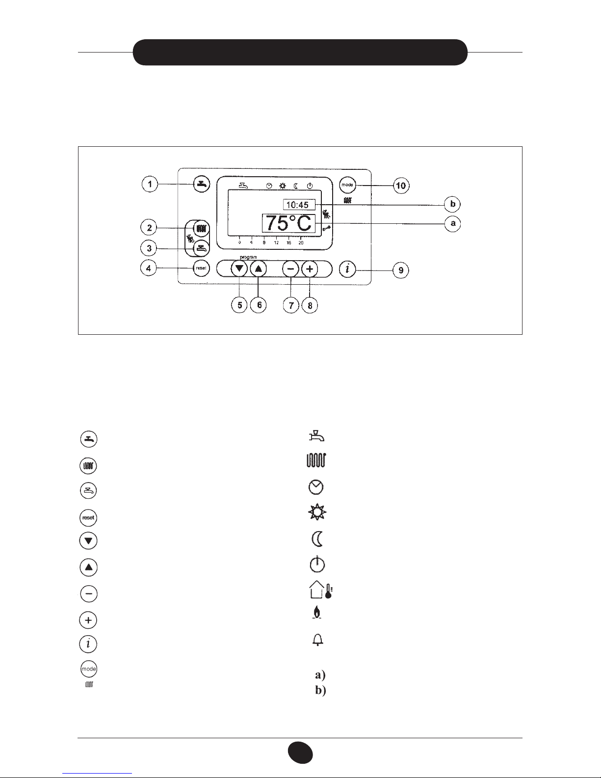
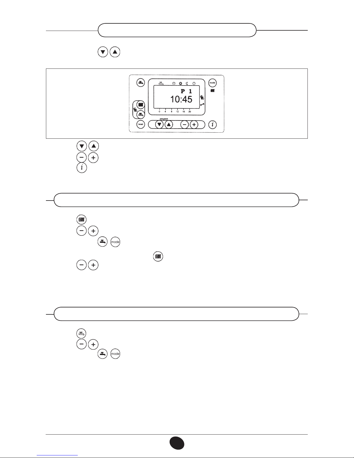
KEYS DISPLAY SYMBOLS
Central heating mode setting key
Data display reset key
Parameter setting key (increase value)
Parameter setting key (decrease value)
Program access and scroll key
Program access and scroll keys
Reset key
Domestic hot water temperature setting key
Central heating water temperature setting key
Domestic hot water on/off key
Resettable alarm warning
MAIN display
SECONDARY display
Flame present (on)
Outdoor temperature
Standby (off)
Operation in manual mode at minimum temperature
Operation in manual mode at the maximum
temperature set
Operation in automatic mode
Operation in central heating mode
Operation in domestic hot water mode
020503_1100
Figure 1
IMPORTANT: Domestic Hot Water (D.H.W.) instructions discribed here, are to be taken into account only
if the boiler is connected to a D.H.W. production system.
To correctly light the burner proceed as follows:
1) Provide power supply to the boiler;
2) Open the gas cock;
3) Follow the directions given below regarding the adjustments to be made at the boiler control panel.
3. COMMISSIONING OF THE BOILER
6
912.823.1 - GB
INSTRUCTIONS PERTAINING TO THE USER
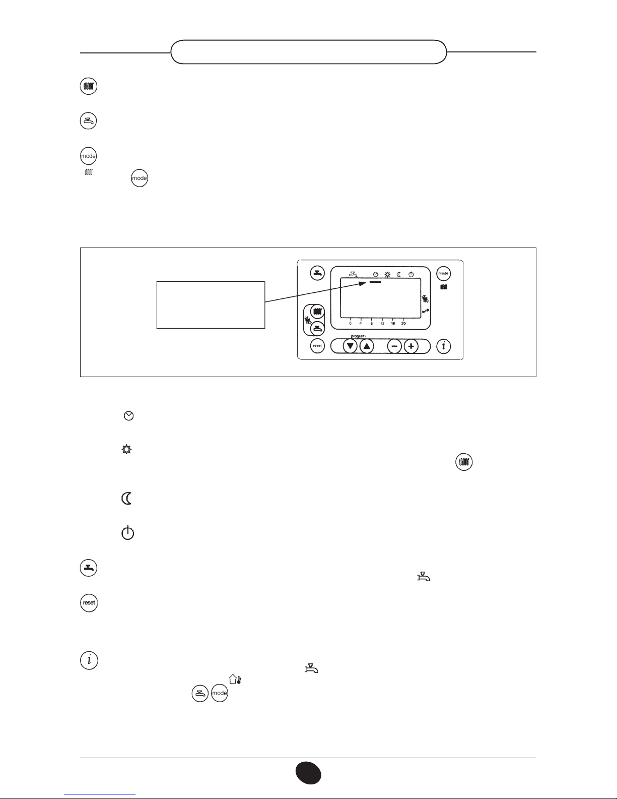
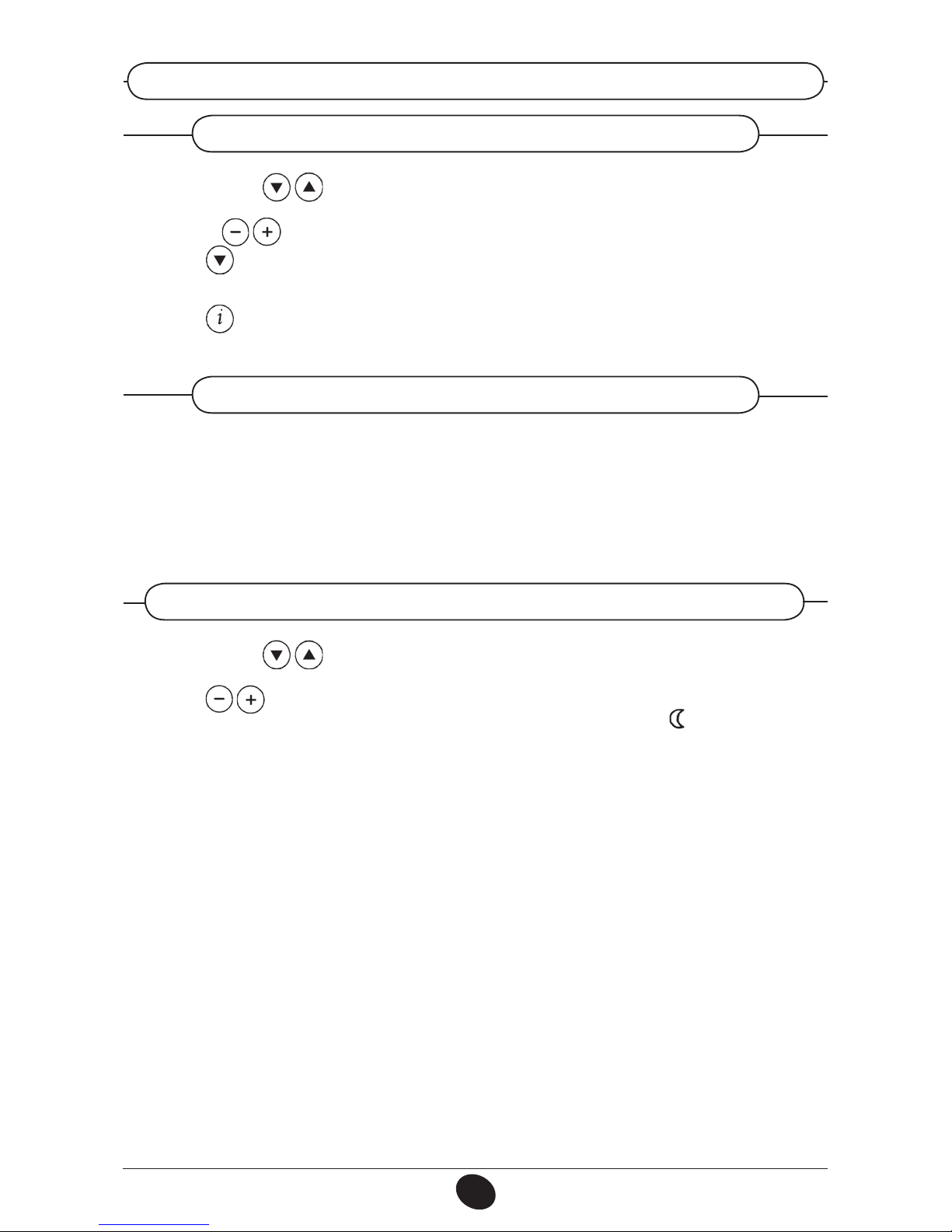
020503_0800
Figure 2
•
Automatic operation. Operation of the boiler is controlled by the timed program as described
in point 3-5.1 “Daily timed program for operation of the central heating system”;
•
Manual operation at the maximum temperature set. The boiler comes into operation regardless
of the timed program set. The operating temperature is that set using the key (point 3-3:
“Setting the maximum central heating temperature”);
•
Manual operation at minimum temperature. The operating temperature is that set in point
3-6: “setting the minimum central heating temperature”.
•
Standby. The boiler does not work in central heating mode, although the antifreeze function is
still enabled.
(1) Domestic hot water on/off key: This key can be pressed to activate or deactivate this function,
which is identied on the display by a black cursor line under the symbol .
(4) Reset key. In case of a fault, referred to in point 3-7 “Faults and resetting the boiler”, the boiler can
be restarted by pressing this key for at least two seconds (see 3-8).
If this key is pressed with no fault present, the display will show the message “E153”, and the same key
has to be pressed again (for at least two seconds) to restart the boiler.
(9) Data key. This key can be pressed repeatedly to display the following information:
- Temperature (°C) of the domestic hot water ( );
- outdoor temperature (°C) ( ); only provided with the outdoor temperature sensor probe connected.
Press either of the keys to return to the main menu.
Dash
“Automatic mode”
active
(2)
Central heating water temperature setting key.
This key can be pressed to set the central heating
water output temperature as described in point 3-3.
(3) Domestic hot water temperature setting key. This key can be pressed to set the domestic hot
water temperature as described in point 3-4.
(10) Central heating mode operating key
.
The key can be pressed to activate four boiler central heating operating modes; these modes are
identied by a black cursor line underneath the relative symbol on the display, and are as follows:
3.1 DESCRIPTION OF KEYS
7
912.823.1 - GB
INSTRUCTIONS PERTAINING TO THE USER
•
Press either of the keys to access the programming function;
the display will show the letter P followed by a number (program line);
•
Press the keys until the display shows P1, referring to the time to be set;
•
Press the keys to set the time; on the display, the letter P will start to ash;
•
Press the key to save and exit the programming function;
020503_0700
Figure 3
3.2 SETTING THE TIME
- Press the key (2-gure 1) to set the central heating water temperature;
- Press the keys to set the temperature required;
- Press either of the keys (1 or 10 - gure 1) to save and return to the main menu.
N.B – With the outdoor sensor connected, the key (2 - gure 1) can be used to shift the central heating curve.
Press the keys to decrease or increase the room temperature in the premises to be heated.
3.3 SETTING THE MAXIMUM CENTRAL HEATING TEMPERATURE
- Press the key (3-gure 1) to set the maximum domestic hot water temperature;
- Press the keys to set the temperature required;
- Press either of the keys (1 or 10 - gure 1) to save and return to the main menu.
3.4 SETTING THE MAXIMUM DOMESTIC HOT WATER TEMPERATURE
8
912.823.1 - GB
INSTRUCTIONS PERTAINING TO THE USER
- Press either of the keys to access the programming function;
a) press these keys until the display shows P11, referring to the program start time;
b) press the keys to set the time;
- Press the key; the display will show P12, referring to the program end time;
- Repeat the operations described in points a and b until the third and last cycle is reached (program line
P16);
- Press the key to save and exit from the programming function.
3.5 SETTING THE DAILY PROGRAM FOR OPERATION IN CENTRAL HEATING AND DOMESTIC HOT WATER MODES
3.5.1 Setting the daily times for central heating mode operation
3.5.2 Setting the daily times for domestic hot water mode operation
- Factory setting of D.H.W. function is enable (ON) while is disabled D.H.W. daily times program. To enable
D.H.W. daily times program see section 14 (parameter H91).
Setting the daily times for domestic hot water mode operation-Carry out the operations described in section
3.5.1 for program lines 31 to 36.
3.6 SETTING THE MINIMUM CENTRAL HEATING TEMPERATURE
- Press either of the keys to access the programming function;
- Press these keys until the display shows P5, referring to the temperature to be set;
- Press the keys to set the temperature required.
This operating mode is enabled when minimum temperature central heating mode “ ” is activated or when
the daily central heating program does not require heat.
N.B – With the outdoor sensor connected, parameter P5 can be used to set the minimum room temperature in the premises to be heated (night set-back).
9
912.823.1 - GB
INSTRUCTIONS PERTAINING TO THE USER
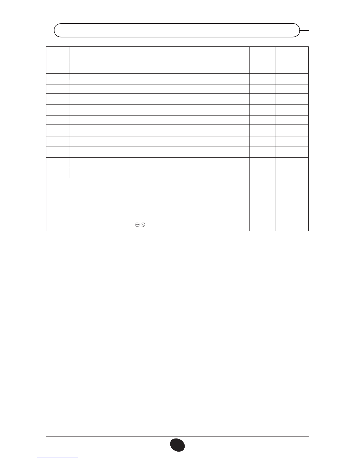
Range
0…23:59
25..80
00:00…24:00
00:00…24:00
00:00…24:00
00:00…24:00
00:00…24:00
00:00…24:00
00:00…24:00
00:00…24:00
00:00…24:00
00:00…24:00
00:00…24:00
00:00…24:00
0...1
Factory
setting
———-
25
6:00
22:00
0:00
0:00
0:00
0:00
0:00
24:00
0:00
0:00
0:00
0:00
0
Parameter description
Time of day setting
Minimum central heating temperature setting (°C)
Start of rst daily period of automatic central heating
End of rst daily period of automatic central heating
Start of second daily period of automatic central heating
End of second daily period of automatic central heating
Start of third daily period of automatic heating
End of third daily period of automatic central heating
Start of rst daily period of domestic hot water production
End of rst daily period of domestic hot water production
Start of second daily period of domestic hot water production
End of second daily period of domestic hot water production
Start of third daily period of domestic hot water production
Fine End of third daily period of domestic hot water production
Reset of daily central heating and domestic hot water production programs (factory settings).
Press the - + keys together for about 3 seconds; the number 1 appears on the display.
Conrm by pressing either of the keys
Parameter
N.
P1
P5
P11
P12
P13
P14
P15
P16
*
P31
*
P32
*
P33
*
P34
*
P35
*
P36
P45
*
Parameters for program lines P31 to P36 are displayed only if Domestic Hot Water (D.H.W.) program (parameter H91 see section 14) is activated.
3.7 TABLE FOR USER-SETTABLE PARAMETERS
10
912.823.1 - GB
INSTRUCTIONS PERTAINING TO THE USER
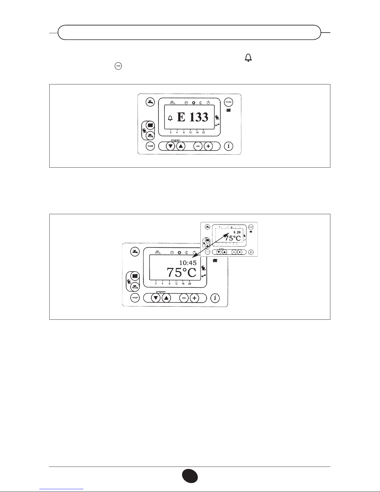
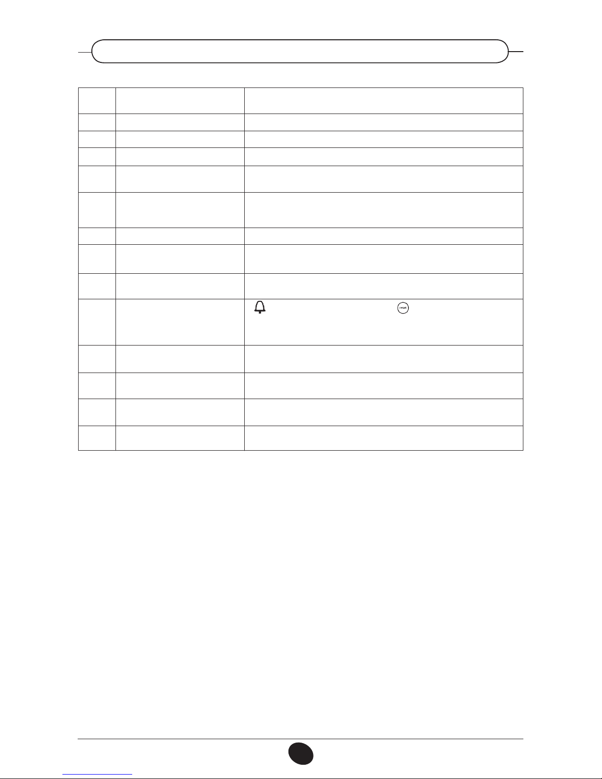
If a fault occurs, a ashing warning code appears on the display.
The fault warnings appear on the main display (gure 1 a) together with the symbol (Figure 4).
To reset, press the reset button for at least two seconds.
020503_0500
Figure 4
020503_0600
Figure 4.1
Fault warnings appear on the secondary display (gure 1 b) alternating with the time, both of them ashing
(gure 4.1). It is not possible to reset malfunction warnings which appear on the secondary display as the cause
of the alarm has rst to be removed.
3.8 FAULT WARNINGS AND RESETTING THE BOILER
11
912.823.1 - GB
INSTRUCTIONS PERTAINING TO THE USER
(*) Auotoreset when fault disappears.
All the faults are displayed in order of importance; if several faults occur simultaneously, the rst to be displayed
is the one with highest priority. After the cause of the rst fault has been removed, the second one will be
displayed, and so on.
If any given fault occurs frequently, contact the authorised Service Centre.
3.9 TABLE OF FAULTS AND ERROR MESSAGES
Corrective action
Call an authorised service centre (*).
Call an authorised service centre (*).
Call an authorised service centre (*).
Press the reset key (for about 2 seconds: if this device is triggered repeatedly, call
the authorised service centre)
Call an authorised service centre.
Call an authorised service centre.
Call an authorised service centre to check the gas pressure.
Press the reset key (for about 2 seconds); if the fault persists, call the authorised
service centre to check polarity of ignition electrodes, ionisation current.
If symbol is displayed, press the reset button otherwise switch off the
electricity supply to the boiler for at least 10 seconds; if the fault persists, call the
authorised service centre.
Check the positioning of the ignition and ame sensing electrode (see section 16).
Press the key again (about 2 seconds)
Press and hold reset button (2 seconds approx.) then press again when warning
E153 appears
Call an authorised service centre.
Check that the system is at the rated pressure. (Refer to the section on lling the
system). If the fault persists, call the authorised service centre.
Description of fault
Outdoor temperature sensor fault
NTC output sensor failure
Hot water NTC sensor failure
Safety or ue gas thermostat tripped
Loss of ame during operation (the
ionization current has fallen below
the limit)
Minimum fan speed limit not reached
Gas pressure switch tripped / external
thermostat tripped
No ame detected
Boiler circuit board error
The reset key h as been pressed
inappropriately
Internal error on boiler circuit module
Fan speed threshold not reached
Low water pressure
Error
code
E10
E20
E50
E110
E128
E129
E132
E133
E151
E153
E154
E160
E164

12
912.823.1 - GB
INSTRUCTIONS PERTAINING TO THE USER
To shut down the boiler switch off the electrical supply to the appliance.
IMPORTANT: Regularly check that the pressure displayed by the pressure gauge is 1 ÷ 4 bar when the central
heating system is cold. Open the boiler drain cock to reduce pressure if it is too high. Open the lling cock to
increase pressure if it is too low.
Always open the lling cock very slowly to allow any air to bleed off.
If the pressure in the system drops frequently, contact an authorised service centre to have the system checked.
We recommend you avoid draining the whole system as raw water makeup will lead to harmful limestone deposits inside the boiler and on the heating elements.
In case the boiler is not operated during wintertime and is therefore exposed to danger of frost we suggest you
add some specic-purpose anti-freeze to the water contained in the system (e.g.: propylene glycole coupled
with corrosion and scaling inhibitors).
The electronic management of the boilers includes a “frost protection” function in the central heating system
which operates the burner to reach a heating ow temperature of 30° C when the system heating ow temperature drops below 5°C.
The frost protection function is enabled if:
* electrical supply to the boiler is on;
* the gas service cock is open;
* the system pressure is as required;
* the boiler is not isolated.
To maintain efcient and safe operation of your boiler have it checked by a Qualied Service Engineer at the
end of every heating season.
Careful servicing will ensure economical operation of the system.
Do not clean the outer casing of the appliance with abrasive, aggressive and/or easily ammable cleaners
(i.e.: gasoline, alcohol, and so on). Always isolate the electrical supply to the appliance before cleaning it (see
section 5 Turning off the boiler).
These boilers are produced for natural gas and can be converted to work with LPG (G 31).
Any gas change must be effected by a Qualified Service Engineer.
4. FILLING THE SYSTEM
5. SWITCHING THE BOILER OFF
6. PROLONGED STANDSTILL OF THE SYSTEM. FROST PROTECTION
7. SERVICING INSTRUCTIONS AND GAS CHANGE

13
912.823.1 - GB
INSTRUCTIONS PERTAINING TO THE INSTALLER
This boiler is designed to heat water at a lower than boiling temperature at atmospheric pressure. The boiler
must be connected to a central heating system and/or to a domestic hot water supply system in compliance
with its performances and output power.
IMPORTANT! The following components are not installed in the boiler as supplied. It is the installer’s
responsibility to provide them:
• Expansion vessel;
• Pressure safety valve;
• Circulation pump;
• Filling system cock.
Before connecting the boiler ensure the following operations have been completed:
a) Check that the boiler is t for operation with the type of gas available. For more details see the notice on the
packaging and the label on the appliance itself.
b) Check that the ue terminal draft is appropriate; that the terminal is not obstructed and that no other applian-
ce exhaust gases are expelled through the same ue duct, unless the ue is especially designed to collect
the exhaust gas coming from more than one appliance, in conformity with the standards and regulations in
force.
c) Check that, in case the ue has been connected to pre-existing ue ducts, thorough cleaning has been carried
out in that residual combustion products may come off during operation of the boiler and obstruct the ue
duct.
The following remarks and instructions are addressed to Service Engineers to help them carry out a faultless
installation. Instructions regarding lighting and operation of the boiler are contained in the ‘Instructions pertaining to the user’ section.
Note that installation, maintenance and operation of the gas appliances must be performed exclusively by
qualied personnel in compliance with current standards.
Please note the following:
• Install the boiler in a permanent ventilated central heating boiler room.
• This boiler can be connected to any type of convector plates, radiators, thermoconvectors. Design the system
sections as usual though taking into account the available output / pump head performances, as shown in
chapter 10.4.
• Do not leave any packaging components (plastic bags, polystyrene, etc.) within children’s reach as they are
a potential source of danger.
• Initial lighting of the boiler must be effected by a Qualied Service Engineer.
• Make sure that the room where the boiler is installed has a sufcient supply of air to ensure complete combu-
stion of the gas consumed by the appliance. Install unblockable ventilation grilles as necessary in accordance
with the Rules in force.
• Connect the boiler directly to an efcient ue to vent all fumes and combustion gases outdoors. Make sure
that the pipe connecting the boiler to the ue is not smaller in diameter than the boiler’s ue outlet. Make
sure that the ue is in good condition and free from holes or cracks that could reduce draw.
Failure to observe the above will render the warranty null and void.
8. GENERAL INFORMATION
9. INSTRUCTIONS PRIOR TO INSTALLATION

14
912.823.1 - GB
INSTRUCTIONS PERTAINING TO THE INSTALLER
10. BOILER INSTALLATION AND DIMENSIONS
Install the boiler in a position that ensures easy maintenance. You must be able to fully open the front access
door and have adequate access to the rear of the boiler.
If possible, install the boiler on a raised base of 200 mm in height to facilitate drainage of ue condensate.
When calculating the weight of the boiler on the oor, bear in mind the weight of the water in the heat exchanger
(see table 1).
Adjust the levelling feet to compensate for any unevenness in the oor.
Install the necessary utility connections starting from the water and gas connections on the rear of the boiler
(see table 1 for tting type and size).
These appliances do not have any circulation pump, expansion tank or safety valve. These devices
must therefore be provided elsewhere in the system, and must be sized to suit the system’s thermal
capacity.
Connect the ue condensate drain pipe to a suitable water drain, ensuring an adequate slope.
To drain the boiler, use the drain tap at the rear.
To ensure correct operation of the appliance and avoid invalidating the warranty, observe the following
precautions:
1. Heating circuit
1.1. New system
Before proceeding with installation of the boiler, the system must be cleaned and ushed out thoroughly to
eliminate residual thread-cutting swarf, solder and solvents if any, using suitable proprietary products.
To avoid damaging metal, plastic and rubber parts, use only neutral cleaners, i.e. non-acid and non
alkaline. The recommended products for cleaning are:
SENTINEL X300 or X400 and FERNOX heating circuit restore. The use of this product must be strictly
in accordance with the maker’s directions. Finally the system must be dosed with a suitable inhibitor at
1% system volume.
1.2. Existing system
Before proceeding with installation of the boiler, the system must be cleaned and ushed out to remove
sludge and contaminants, using suitable proprietary products as described in section 1.1.
To avoid damaging metal, plastic and rubber parts, use only neutral cleaners, i.e. non-acid and non-
alkaline such us SENTINEL X100 and FERNOX heating circuit protective. To use this product proceeding
strictly in accordance with the maker’s directions.
Remember that the presence of foreign matter in the heating system can adversely affect the operation
of the boiler (e.g. overheating and noisy operation of the heat exchanger). Dose with inhibitor.
Failure to observe the above will render the warranty null and void.
 Loading...