

Baxi QAC34 Installation, Commissioning And User Instructions

en
United Kingdom
These instructions should be read in conjunction with the
Boiler Installation and Service Manual and left with the User when completed.
Please keep these instructions in a safe place.
If you move house please hand them over to the next occupier.
Part No. 7703233
Suitable for Combination boilers ONLY
Installation & Commissioning and User Instructions
On Wall Outdoor Sensor Kit - Combi (QAC34)
Multifit

7703237-01 (3/18)
Outdoor Sensor Kit (QAC34)
Regulation EU811/2013, supplementing Ecodesign and
Energy Labelling Directives 2010/30EU
Part
Number
This Thermostatic
Control Device is rated
Correction Factor
(Contribution to system
energy efficiency)
7703233
Class ‘II’ 2 %
ErP Information
The Outdoor Sensor is suitable for use with the
following boilers:-
BOILER GROUP ‘A’
Baxi Duo-tec Combi range
Baxi Platinum Combi range
Main Eco Elite Combi range
Potterton Promax Combi range
Potterton Gold Combi range
Potterton Titanium Combi range
BOILER GROUP ‘B’
Baxi 100 Combi range
Potterton Promax Ultra Combi range
BOILER GROUP ‘C’
Baxi EcoBlue + Combi & Advance Combi ranges
BOILER GROUP ‘D’
Baxi 200 Combi range
Baxi 400 Combi range
BOILER GROUP ‘E’
Baxi 600 Combi range
Potterton Assure Combi range
Refer to the Installation & Service Manual supplied with the
appliance if the boiler being installed is not on the above list.
Contents
Section Page
1.0 Legislation 2
2.0 Introduction 3
3.0 Contents of pack 3
4.0 Fitting the outdoor sensor 4
5.0 Connecting the outdoor sensor
boiler group ‘A’ 5
6.0 Setting the outdoor sensor curve
boiler group ‘A’ 6
7.0 Connecting the outdoor sensor
& setting the curve boiler group ‘B’ 7
8.0 Connecting the outdoor sensor
boiler group ‘C’ 8
9.0 Setting the outdoor sensor parameters
boiler group ‘C’ 8
10.0 Operating instructions outdoor sensor
boiler group ‘C’ 9
11.0 Fault finding boiler group ‘C’ 10
12.0 Connecting the outdoor sensor & setting
the slope boiler group ‘D’ 11
13.0 Connecting the outdoor sensor & setting
the curve boiler group ‘E’ 12
14.0 Notes 13
15.0 User Information 15
1.0 Legislation
NOTES: This kit is suitable only for installation in GB and IE and should be installed in accordance with the rules in force.
In GB, the installation must be carried out by a Gas Safe Registered Installer. It must be carried out in accordance with
the relevant requirements of the:
• Gas Safety (Installation & Use) Regulations.
• The appropriate Building Regulations either:The Building Regulations,The Building Regulations
(Scotland), Building Regulations (Northern Ireland).
• The Water Fittings Regulations or Water Byelaws in Scotland.
• The Current I.E.E.Wiring Regulations.
Where no specific instructions are given, reference should be made to the relevant British Standard Code of Practice.
In IE, the installation must be carried out by a competent Person and installed in accordance with the current edition of
I.S. 813 'Domestic Gas Installations', the current Building Regulations and reference should be made to the current ETCI
rules for electrical installation.
2
7703237-01 (3/18)
2
.0 Introduction
1. The Outdoor Sensor kit positions a temperature sensor on a
suitable outside wall. Installation of this kit permits the
c
ustomer to gain the efficiency benefits of outdoor weather
temperature compensation control. The sensor allows the
outdoor temperature to be taken into consideration and the
b
oiler flow temperature regulated accordingly to provide
required comfort levels.
2
. The curve determining boiler flow temperature should be set
as low as possible but still maintaining required comfort levels.
The selected curve must be noted on the identifying label to be
a
ffixed to the boiler.
3. The addition of anything that may interfere with the
n
ormal operation of the appliance without express written
permission from the manufacturer could invalidate this kit and
the appliance warranty. In GB this could also infringe the Gas
Safety (Installation and use) Regulations.
4. This kit is only suitable for use with the boiler ranges listed
by group on page 2.
Conventional Controls: Standard mains voltage ON/OFF
controls do not affect the method of setting the curve or
boiler operation when the outdoor sensor is fitted.
Conventional controls in conjunction with an outdoor sensor
represent the simplest solution.
OpenTherm Controls: If an OpenTherm control is also to
be connected to the boiler this must be taken into
consideration as some devices affect the operation of the
boiler control knobs or buttons. Depending on the device
used it is possible that the OpenTherm control will assume
the role of “master”, rendering the boiler controls
inoperative or altering their function.
It is recommended that the outdoor sensor is fitted and set
prior to connecting any OpenTherm device. Consult the
instructions supplied with such devices before setting the
curve. The Baxi uSense device is recommended for this
type of control application.
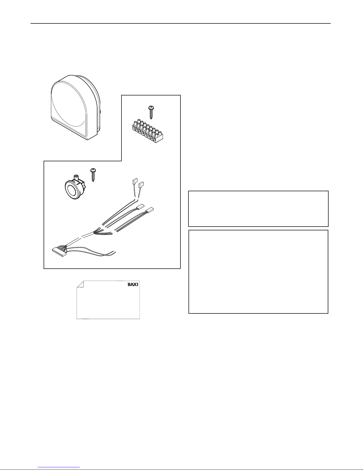
3.0 Contents of Pack
Description
(i) Outdoor Sensor (QAC34)
(ii) M2 Terminal Strip & Screw (for boilers in Group ‘A’ only)
(iii) Replacement Harness (for boilers in Group ‘A’ only)
(iv) Grommet & Screw (for boilers in Group ‘A’ only)
(v) Identifying Label
(i)
(ii)
(iii)
(iv)
(v)
For boilers in
Group ‘A’ ONLY
For boilers in
Group ‘A’ ONLY
I
FO
S
ErP
C
l
a
ss
I
I
“I c
erti
fy
that thi
s
boi
l
er i
s
c
onnec
te
d to a w
eather c
om
pens
ati
on
tem
perature s
ens
or w
hi
c
h i
s
c
om
p
ati
bl
e w
i
th the boi
l
er &
prov
i
des
w
eather c
om
pens
ati
on c
ontrol
tha
t has
been perm
anentl
y
enabl
ed.
The boi
l
er has
been c
om
m
i
s
s
i
oned i
n ac
c
ordanc
e w
i
th
M
anufac
turer i
ns
truc
ti
ons
w
hi
c
h h
av
e been s
uppl
i
ed to the
H
ous
ehol
der
.
The C
entral
H
eati
ng c
ontrol
s
houl
d be s
et s
o that a
v
al
ue of _____________ i
s
di
s
pl
ay
e
d or i
n the _______ pos
i
ti
on.”
S
i
gned: __________________ D
a
te: ________
B
a
x
i
,
B
r
o
o
k
s
H
o
u
s
e
,
C
o
v
e
n
t
r
y
R
o
a
d
,
Wa
r
w
i
c
k
,
C
V
3
4
4
L
L
B
a
x
i
C
u
s
t
o
m
e
r
S
u
p
p
o
r
t
0
3
4
4
8
7
1
1
5
4
5
7
6
8
7
8
0
1
-
0
1
(
2
/
1
8
)
Outdoor Sensor Kit (QAC34)
3
4
7703237-01 (3/18)
Outdoor Sensor Kit (QAC34)
4
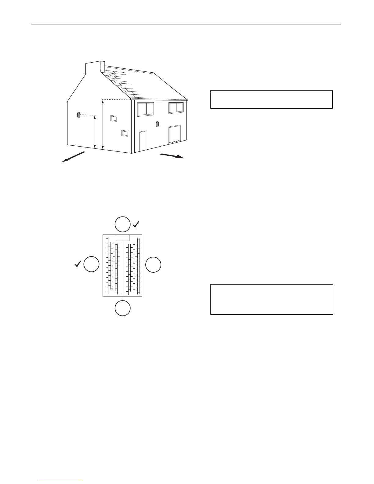
.0 Fitting the Outdoor Sensor - All
Models
1. The Sensor must be fixed to an external wall
surface.
2. The Sensor should be positioned on a north to
west facing wall (Figs. 1 & 2) .
NOTE: DO NOT position it on a south facing wall
in direct sunlight !
3. The Sensor should be positioned approximately
half the height of the living space of the property, and
a minimum of 2.5m above ground level (Fig. 1).
4. It must be positioned away from any sources of
heat or cooling (e.g. flue terminal) to ensure accurate
operation. Siting the Sensor above doors and
windows, adjacent to vents and close to eaves
should be avoided.
5. Once the position has been determined, prise the
cover off the sensor and mark through the sensor
body the two fixing holes and the larger hole for the
wiring.
6. Drill & plug the two fixing holes (plugs and screws
are supplied with the Sensor). Also drill the hole for
the sensor wiring cable.
7. Insert the sensor wiring cable through the hole in
the wall, leaving sufficient length outside to allow
connection. Seal the hole. Note: 0.5mm 2 core
cable is recommended (the Sensor is a low voltage
device). This wiring cable is NOT supplied in the kit.
NOTE: If it is not possible to pass the wiring cable
through the wall directly behind, remove the
circular ‘knock-out’ panel in the sensor base to
allow connection.
8. Using the screws provided fit the body to the wall.
Insert the wires in the two-way terminal block and
secure them. Replace the Sensor cover.
Fig. 1
Fig. 2
North
West
1/2 H
2.5m Min
H
N
S
WE
X
X
7703237-01 (3/18)
5
Outdoor Sensor Kit (QAC34)
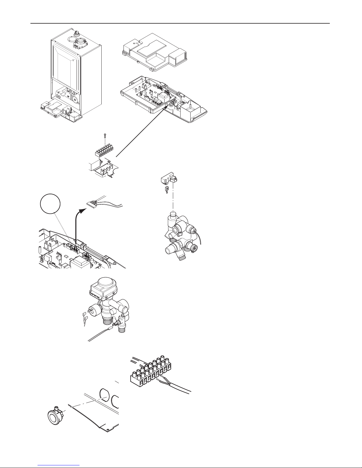
5
.0 Connecting the Sensor - boiler
Group ‘A’
1. Ensure that the electrical supply to the boiler is
isolated. Undo the screws securing the facia and lift
off the front panel. Allow the facia to drop down (Fig.
3).
2. Undo the screws securing the cover and release
the cover retaining barbs from their slots. Disengage
the rear of the cover from the facia hinge pin and lift
the cover away (Fig. 4).
3. Do not touch the PCB unnecessarily, and take
care when removing and fitting connectors.
4. Engage the M2 low voltage 8 way terminal strip
over the vertical flanges and secure with the screw
supplied (Fig. 5).
5. Disconnect the harness connector from position
X400 on the PCB (Fig. 6).
6. Disconnect the wiring from the Hall Effect Sensor,
DHW NTC and Water Pressure Switch (Figs. 7 & 8).
Retain the Hall Effect Sensor.
7. Connect the new harness supplied to position
X400 on the PCB.
8. Connect the harness terminals to the Hall Effect
Sensor, DHW NTC and Water Pressure Switch (see
Figs. 7 & 8). Refit the Hall Effect Sensor.
9. Connect the two brown wires on the new harness
to 4 & 5 on the M2 low voltage 8 way terminal strip
(Fig. 9).
10. Route
the cable from the Outdoor Sensor to the
boiler, and using the cable grommet supplied pass it
through the hydraulic panel at the lower right (Fig. 10).
10. Connect the Outdoor Sensor cable to 4 & 5 on
the M2 low voltage 8 way terminal strip (Fig. 9).
There is no polarity.
11. Refit the cover, resecure the facia and door
panel.
Fig. 6
Fig. 7
Fig. 8
Fig. 9
X400
Fig. 10
Combi Hall
Effect Sensor
Combi Water
Pressure Switch &
DHW NTC
M2 low voltage
terminal strip
br
b
r
1
2
3
4
5
6
7
8
br
br
Sensor Cable
Brown Wires from
New Harness
(X400)
Fig. 3
Fig. 4
Fig. 5
 Loading...