

Page 1
Italy
en
User Guide
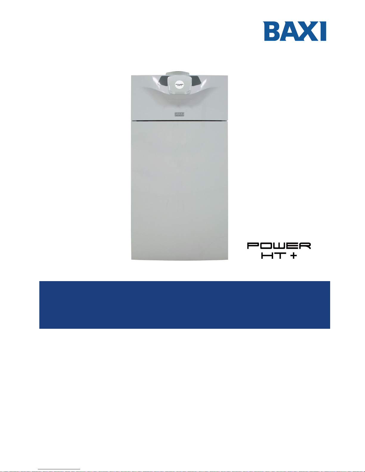
Gas fired floor-standing condensing boiler
POWER HT+ 1.50
POWER HT+ 1.70
POWER HT+ 1.90
POWER HT+ 1.110
Page 2

Dear customer,
Thank you for purchasing this appliance.
Please read this manual carefully before using the product and keep it in a safe place for future reference.
In order to ensure continued safe and efficient operation we recommend that the product is regularly maintained. Our Service
and After Sales organization can assist with this.
We hope you will receive many years of satisfactory service.
Page 3

Contents
1 Safety . . . . . . . . . . . . . . . . . . . . . . . . . . . . . . . . . . . . . . . . . . . . . . . . . . . . . . . . . . . . . . . . . . . . . . . . . . 5
1.1 General safety instructions . . . . . . . . . . . . . . . . . . . . . . . . . . . . . . . . . . . . . . . . . . . . . . . . . . . . . . 5
1.2 Recommendations . . . . . . . . . . . . . . . . . . . . . . . . . . . . . . . . . . . . . . . . . . . . . . . . . . . . . . . . . . . . 6
1.3 Liabilities . . . . . . . . . . . . . . . . . . . . . . . . . . . . . . . . . . . . . . . . . . . . . . . . . . . . . . . . . . . . . . . . . . . . 7
1.3.1 User's liability . . . . . . . . . . . . . . . . . . . . . . . . . . . . . . . . . . . . . . . . . . . . . . . . . . . . . . . . . . 7
1.3.2 Installer's liability . . . . . . . . . . . . . . . . . . . . . . . . . . . . . . . . . . . . . . . . . . . . . . . . . . . . . . . .8
1.3.3 Manufacturer's liability . . . . . . . . . . . . . . . . . . . . . . . . . . . . . . . . . . . . . . . . . . . . . . . . . . . 8
2 About this manual . . . . . . . . . . . . . . . . . . . . . . . . . . . . . . . . . . . . . . . . . . . . . . . . . . . . . . . . . . . . . . . . . . . . . . . . . . . . . . . . . . . 9
2.1 General . . . . . . . . . . . . . . . . . . . . . . . . . . . . . . . . . . . . . . . . . . . . . . . . . . . . . . . . . . . . . . . . . . . . . . . . . . . . . . . . . . . . . . 9
2.2 Symbols used . . . . . . . . . . . . . . . . . . . . . . . . . . . . . . . . . . . . . . . . . . . . . . . . . . . . . . . . . . . . . . . . . . . . . . . . . . . . . . . . . 9
2.2.1 Symbols used in the manual . . . . . . . . . . . . . . . . . . . . . . . . . . . . . . . . . . . . . . . . . . . . . . . . . . . . . . . . . . . . . . 9
2.2.2 Symbols used on the appliance . . . . . . . . . . . . . . . . . . . . . . . . . . . . . . . . . . . . . . . . . . . . . . . . . . . . . . . . . . . .9
3 Technical specifications . . . . . . . . . . . . . . . . . . . . . . . . . . . . . . . . . . . . . . . . . . . . . . . . . . . . . . . . . . . . . . . . . . . . . . . . . . . . . 10
3.1 Homologations . . . . . . . . . . . . . . . . . . . . . . . . . . . . . . . . . . . . . . . . . . . . . . . . . . . . . . . . . . . . . . . . . . . . . . . . . . . . . . . 10
3.1.1 Ecodesign Directive . . . . . . . . . . . . . . . . . . . . . . . . . . . . . . . . . . . . . . . . . . . . . . . . . . . . . . . . . . . . . . . . . . . 10
3.1.2 Certifications . . . . . . . . . . . . . . . . . . . . . . . . . . . . . . . . . . . . . . . . . . . . . . . . . . . . . . . . . . . . . . . . . . . . . . . . . 10
3.2 Technical data . . . . . . . . . . . . . . . . . . . . . . . . . . . . . . . . . . . . . . . . . . . . . . . . . . . . . . . . . . . . . . . . . . . . . . . . . . . . . . . .10
3.2.1 Other technical parameters . . . . . . . . . . . . . . . . . . . . . . . . . . . . . . . . . . . . . . . . . . . . . . . . . . . . . . . . . . . . . . 11
3.2.2 Sensor specifications . . . . . . . . . . . . . . . . . . . . . . . . . . . . . . . . . . . . . . . . . . . . . . . . . . . . . . . . . . . . . . . . . . .12
4 Description of the product . . . . . . . . . . . . . . . . . . . . . . . . . . . . . . . . . . . . . . . . . . . . . . . . . . . . . . . . . . . . . . . . . . . . . . . . . . . . 13
4.1 General description . . . . . . . . . . . . . . . . . . . . . . . . . . . . . . . . . . . . . . . . . . . . . . . . . . . . . . . . . . . . . . . . . . . . . . . . . . . .13
4.2 Operating principle . . . . . . . . . . . . . . . . . . . . . . . . . . . . . . . . . . . . . . . . . . . . . . . . . . . . . . . . . . . . . . . . . . . . . . . . . . . . 13
4.2.1 Circulation pump . . . . . . . . . . . . . . . . . . . . . . . . . . . . . . . . . . . . . . . . . . . . . . . . . . . . . . . . . . . . . . . . . . . . . . 13
4.2.2 Gas/air setting . . . . . . . . . . . . . . . . . . . . . . . . . . . . . . . . . . . . . . . . . . . . . . . . . . . . . . . . . . . . . . . . . . . . . . . . 13
4.2.3 Low-loss header (accessory) . . . . . . . . . . . . . . . . . . . . . . . . . . . . . . . . . . . . . . . . . . . . . . . . . . . . . . . . . . . . .13
4.2.4 System in cascade . . . . . . . . . . . . . . . . . . . . . . . . . . . . . . . . . . . . . . . . . . . . . . . . . . . . . . . . . . . . . . . . . . . . .14
4.2.5 Settings and safety devices . . . . . . . . . . . . . . . . . . . . . . . . . . . . . . . . . . . . . . . . . . . . . . . . . . . . . . . . . . . . . .15
4.3 Main components . . . . . . . . . . . . . . . . . . . . . . . . . . . . . . . . . . . . . . . . . . . . . . . . . . . . . . . . . . . . . . . . . . . . . . . . . . . . . 16
4.4 Control panel description . . . . . . . . . . . . . . . . . . . . . . . . . . . . . . . . . . . . . . . . . . . . . . . . . . . . . . . . . . . . . . . . . . . . . . . 17
4.4.1 Description of the keys . . . . . . . . . . . . . . . . . . . . . . . . . . . . . . . . . . . . . . . . . . . . . . . . . . . . . . . . . . . . . . . . . 17
4.4.2 Description of the symbols . . . . . . . . . . . . . . . . . . . . . . . . . . . . . . . . . . . . . . . . . . . . . . . . . . . . . . . . . . . . . . .17
5 Operation . . . . . . . . . . . . . . . . . . . . . . . . . . . . . . . . . . . . . . . . . . . . . . . . . . . . . . . . . . . . . . . . . . . . . . . . . . . . . . . . . . . . . . . . .18
5.1 Use of the control panel . . . . . . . . . . . . . . . . . . . . . . . . . . . . . . . . . . . . . . . . . . . . . . . . . . . . . . . . . . . . . . . . . . . . . . . . 18
5.1.1 Modifying the user parameters . . . . . . . . . . . . . . . . . . . . . . . . . . . . . . . . . . . . . . . . . . . . . . . . . . . . . . . . . . . 18
5.2 Starting up the boiler . . . . . . . . . . . . . . . . . . . . . . . . . . . . . . . . . . . . . . . . . . . . . . . . . . . . . . . . . . . . . . . . . . . . . . . . . . .18
5.3 Stopping the boiler . . . . . . . . . . . . . . . . . . . . . . . . . . . . . . . . . . . . . . . . . . . . . . . . . . . . . . . . . . . . . . . . . . . . . . . . . . . . 18
5.3.1 Putting the boiler in Standby mode . . . . . . . . . . . . . . . . . . . . . . . . . . . . . . . . . . . . . . . . . . . . . . . . . . . . . . . . 18
5.4 Frost Protection . . . . . . . . . . . . . . . . . . . . . . . . . . . . . . . . . . . . . . . . . . . . . . . . . . . . . . . . . . . . . . . . . . . . . . . . . . . . . . .18
5.4.1 Activating the Off . . . . . . . . . . . . . . . . . . . . . . . . . . . . . . . . . . . . . . . . . . . . . . . . . . . . . . . . . . . . . . . . . . . . . . 19
6 Settings . . . . . . . . . . . . . . . . . . . . . . . . . . . . . . . . . . . . . . . . . . . . . . . . . . . . . . . . . . . . . . . . . . . . . . . . . . . . . . . . . . . . . . . . . . 20
6.1 List of parameters . . . . . . . . . . . . . . . . . . . . . . . . . . . . . . . . . . . . . . . . . . . . . . . . . . . . . . . . . . . . . . . . . . . . . . . . . . . . . 20
6.1.1 Shortcuts menu . . . . . . . . . . . . . . . . . . . . . . . . . . . . . . . . . . . . . . . . . . . . . . . . . . . . . . . . . . . . . . . . . . . . . . . 20
6.1.2 Information menu . . . . . . . . . . . . . . . . . . . . . . . . . . . . . . . . . . . . . . . . . . . . . . . . . . . . . . . . . . . . . . . . . . . . . .20
6.1.3 List of user parameters . . . . . . . . . . . . . . . . . . . . . . . . . . . . . . . . . . . . . . . . . . . . . . . . . . . . . . . . . . . . . . . . . 21
6.2 Setting the parameters . . . . . . . . . . . . . . . . . . . . . . . . . . . . . . . . . . . . . . . . . . . . . . . . . . . . . . . . . . . . . . . . . . . . . . . . . 23
6.2.1 Setting the date and time . . . . . . . . . . . . . . . . . . . . . . . . . . . . . . . . . . . . . . . . . . . . . . . . . . . . . . . . . . . . . . . .23
6.2.2 Language Selection . . . . . . . . . . . . . . . . . . . . . . . . . . . . . . . . . . . . . . . . . . . . . . . . . . . . . . . . . . . . . . . . . . . .24
6.2.3 Setting a temporary heating flow temperature . . . . . . . . . . . . . . . . . . . . . . . . . . . . . . . . . . . . . . . . . . . . . . . .25
6.2.4 Changing the operating mode . . . . . . . . . . . . . . . . . . . . . . . . . . . . . . . . . . . . . . . . . . . . . . . . . . . . . . . . . . . 25
6.2.5 Forcing domestic hot water production . . . . . . . . . . . . . . . . . . . . . . . . . . . . . . . . . . . . . . . . . . . . . . . . . . . . . 26
6.2.6 Setting the room temperature set point (Onmode) . . . . . . . . . . . . . . . . . . . . . . . . . . . . . . . . . . . . . . . . . . . . 26
6.2.7 Modifying the domestic hot water production mode . . . . . . . . . . . . . . . . . . . . . . . . . . . . . . . . . . . . . . . . . . . 27
6.2.8 Setting the domestic hot water temperature set point . . . . . . . . . . . . . . . . . . . . . . . . . . . . . . . . . . . . . . . . . . 27
6.2.9 Setting the room temperature set point (Reduced mode) . . . . . . . . . . . . . . . . . . . . . . . . . . . . . . . . . . . . . . . 28
6.2.10 Programming a Holiday period . . . . . . . . . . . . . . . . . . . . . . . . . . . . . . . . . . . . . . . . . . . . . . . . . . . . . . . . . . . 29
6.2.11 Selecting a heating circuit . . . . . . . . . . . . . . . . . . . . . . . . . . . . . . . . . . . . . . . . . . . . . . . . . . . . . . . . . . . . . . . 32
6.3 Accessing the information menu . . . . . . . . . . . . . . . . . . . . . . . . . . . . . . . . . . . . . . . . . . . . . . . . . . . . . . . . . . . . . . . . . .32
Contents
7609475 - v04 - 15072015 POWER HT + 3
Page 4

7 Maintenance . . . . . . . . . . . . . . . . . . . . . . . . . . . . . . . . . . . . . . . . . . . . . . . . . . . . . . . . . . . . . . . . . . . . . . . . . . . . . . . . . . . . . . 33
7.1 General . . . . . . . . . . . . . . . . . . . . . . . . . . . . . . . . . . . . . . . . . . . . . . . . . . . . . . . . . . . . . . . . . . . . . . . . . . . . . . . . . . . . . 33
8 Troubleshooting . . . . . . . . . . . . . . . . . . . . . . . . . . . . . . . . . . . . . . . . . . . . . . . . . . . . . . . . . . . . . . . . . . . . . . . . . . . . . . . . . . . .34
8.1 Error codes . . . . . . . . . . . . . . . . . . . . . . . . . . . . . . . . . . . . . . . . . . . . . . . . . . . . . . . . . . . . . . . . . . . . . . . . . . . . . . . . . . 34
8.1.1 Automatic error code clearing . . . . . . . . . . . . . . . . . . . . . . . . . . . . . . . . . . . . . . . . . . . . . . . . . . . . . . . . . . . . 34
8.1.2 Clearing error codes . . . . . . . . . . . . . . . . . . . . . . . . . . . . . . . . . . . . . . . . . . . . . . . . . . . . . . . . . . . . . . . . . . . 34
9 Environmental . . . . . . . . . . . . . . . . . . . . . . . . . . . . . . . . . . . . . . . . . . . . . . . . . . . . . . . . . . . . . . . . . . . . . . . . . . . . . . . . . . . . . 35
9.1 Energy savings . . . . . . . . . . . . . . . . . . . . . . . . . . . . . . . . . . . . . . . . . . . . . . . . . . . . . . . . . . . . . . . . . . . . . . . . . . . . . . . 35
9.2 Room thermostat and settings . . . . . . . . . . . . . . . . . . . . . . . . . . . . . . . . . . . . . . . . . . . . . . . . . . . . . . . . . . . . . . . . . . . 35
10 Disposal . . . . . . . . . . . . . . . . . . . . . . . . . . . . . . . . . . . . . . . . . . . . . . . . . . . . . . . . . . . . . . . . . . . . . . . . . . . . . . . . . . . . . . . . . .36
10.1 Disposal and Recycling . . . . . . . . . . . . . . . . . . . . . . . . . . . . . . . . . . . . . . . . . . . . . . . . . . . . . . . . . . . . . . . . . . . . . . . . .36
11 Warranty . . . . . . . . . . . . . . . . . . . . . . . . . . . . . . . . . . . . . . . . . . . . . . . . . . . . . . . . . . . . . . . . . . . . . . . . . . . . . . . . . . . . . . . . . 37
11.1 General . . . . . . . . . . . . . . . . . . . . . . . . . . . . . . . . . . . . . . . . . . . . . . . . . . . . . . . . . . . . . . . . . . . . . . . . . . . . . . . . . . . . . 37
11.2 Terms of warranty . . . . . . . . . . . . . . . . . . . . . . . . . . . . . . . . . . . . . . . . . . . . . . . . . . . . . . . . . . . . . . . . . . . . . . . . . . . . . 37
12 Appendix . . . . . . . . . . . . . . . . . . . . . . . . . . . . . . . . . . . . . . . . . . . . . . . . . . . . . . . . . . . . . . . . . . . . . . . . . . . . . . . . . . . . . . . . . 38
12.1 Product fiche - Boiler space heaters . . . . . . . . . . . . . . . . . . . . . . . . . . . . . . . . . . . . . . . . . . . . . . . . . . . . . . . . . . . . . . . 38
12.2 Product fiche - Temperature Controls . . . . . . . . . . . . . . . . . . . . . . . . . . . . . . . . . . . . . . . . . . . . . . . . . . . . . . . . . . . . . .38
12.3 Package fiche . . . . . . . . . . . . . . . . . . . . . . . . . . . . . . . . . . . . . . . . . . . . . . . . . . . . . . . . . . . . . . . . . . . . . . . . . . . . . . . . 39
Contents
4 POWER HT + 7609475 - v04 - 15072015
Page 5
1 Safety
1.1 General safety instructions
Danger
This appliance can be used by children aged from 8
years and above and persons with reduced physical,
sensory or mental capabilities or lack of experience
and knowledge if they have been given supervision or
instruction concerning use of the appliance in a safe
way and understand the hazards involved. Children
shall not play with the appliance. Cleaning and user
maintenance shall not be made by children without
supervision.
Danger
If you smell gas:
1. Do not use a naked flame, do not smoke, do not
operate electrical contacts or switches (doorbell,
light, motor, lift, etc.).
2. Shut off the gas supply.
3. Open the windows.
4. Trace possible leaks and seal them immediately.
5. If the gas leak is before the gas meter, contact the
gas supplier.
Danger
If you smell flue gases:
1. Switch off the appliance.
2. Open the windows.
3. Trace possible leaks and seal them immediately.
Warning
Do not touch the flue gas pipes. Depending on the
boiler settings, the temperature of the flue gas pipes
may exceed 60°C.
Warning
Do not touch the radiators for long periods. Depending
on the boiler settings, the temperature of the radiators
may exceed 60°C.
Warning
Take precautions with the domestic hot water. De
pending on the boiler settings, the domestic hot water
temperature may exceed 65°C.
Danger of electric shock
Before any work, switch off the mains supply to the
boiler.
1 Safety
7609475 - v04 - 15072015 POWER HT + 5
Page 6
1.2
Recommendations
Note
Keep this document close to the place where the ap
pliance is installed.
Note
Never remove or cover labels and data plates affixed
to the appliances. Labels and data plates must be
legible throughout the entire lifetime of the appliance.
Immediately replace damaged or illegible instructions
and warning stickers.
Caution
The appliance should be on Summer or Antifreeze
mode rather than switched off to guarantee the follow
ing functions:
Anti-blocking of pumps
Frost Protection
Caution
If the home is unoccupied for a long period and there
is a risk of frost, drain the boiler and the heating sys
tem.
Caution
To enjoy warranty cover, no modifications must be
made to the appliance.
Caution
The frost protection does not work if the boiler is
switched off.
Caution
The integrated protection system only protects the
boiler, not the heating installation
Caution
Remove the boiler casing only to perform mainte
nance and repair work. Always put the casing back in
place after such work.
Warning
Only qualified professionals are authorised to work on
the boiler and the heating installation.
Note
Keep the boiler accessible at all times.
Caution
Installation of the boiler must be done by a qualified
professional in accordance with prevailing local and
national regulations.
Caution
Install the boiler in a frost-free location.
1 Safety
6 POWER HT + 7609475 - v04 - 15072015
Page 7
Caution
Do not stock chloride or fluoride compounds close to
the boiler. They are particularly corrosive and may
contaminate the combustive air. Chloride and fluoride
compounds are present in aerosol sprays, paints, sol
vents, cleaning products, washing products, deter
gents, glues, snow clearing salts.
Caution
Do not neglect to service the boiler. Contact a quali
fied professional or subscribe to a maintenance con
tract for the annual servicing of the boiler.
Note
Regularly check the presence of water and pressure
in the heating installation.
Caution
Maintenance work must be carried out by a qualified
professional.
Caution
Only a qualified professional is authorised to clean the
inside of the boiler.
Caution
Only genuine spare parts may be used.
Caution
After maintenance or repair work, check the entire
heating installation to ensure that there are no leaks.
Warning
Ensure correct earthing.
Install the appliance on a solid, stable structure able
to bear its weight.
Warning
Removal and disposal of the boiler must be carried
out by a qualified installer in accordance with local
and national regulations
Caution
If the power cord is damaged, it must be replaced by
the manufacturer, its after sales service or persons
with similar qualifications in order to obviate any dan
ger.
1.3
Liabilities
1.3.1 User's liability
To guarantee optimum operation of the system, you must
abide by the following instructions:
Read and follow the instructions given in the manuals pro
vided with the appliance.
1 Safety
7609475 - v04 - 15072015 POWER HT + 7
Page 8

Call on a qualified professional to carry out installation and
initial commissioning.
Get your installer to explain your installation to you.
Have the required inspections and maintenance carried out
by a qualified installer.
Keep the instruction manuals in good condition close to the
appliance.
1.3.2
Installer's liability
The installer is responsible for the installation and initial com
missioning of the appliance. The installer must abide by the
following instructions:
Read and follow the instructions given in the manuals pro
vided with the appliance.
Install the appliance in compliance with prevailing legisla
tion and standards.
Carry out initial commissioning and any checks necessary.
Explain the installation to the user.
If maintenance is necessary, warn the user of the obliga
tion to check the appliance and keep it in good working or
der.
Give all the instruction manuals to the user.
1.3.3 Manufacturer's liability
Our products are manufactured in compliance with the re
quirements of the various Directives applicable. They are
therefore delivered with the
marking and any documents
necessary. In the interests of the quality of our products, we
strive constantly to improve them. We therefore reserve the
right to modify the specifications given in this document.
Our liability as manufacturer may not be invoked in the fol
lowing cases:
Failure to abide by the instructions on installing the appli
ance.
Failure to abide by the instructions on using the appliance.
Faulty or insufficient maintenance of the appliance.
1 Safety
8 POWER HT + 7609475 - v04 - 15072015
Page 9
2 About this manual
2.1 General
This manual is intended for the user of a POWER HT + heat pump. This
manual can also be found on our internet site.
2.2
Symbols used
2.2.1 Symbols used in the manual
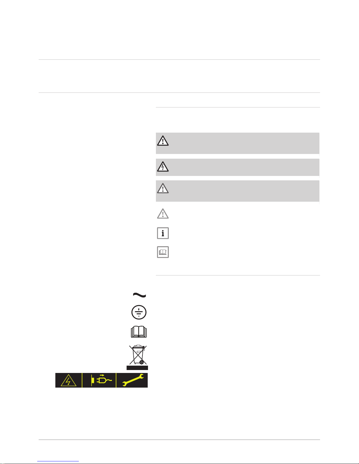
This manual uses various danger levels to draw attention to special in
structions. We do this to improve user safety, to prevent problems and to
guarantee correct operation of the appliance.
Danger
Risk of dangerous situations that may result in serious personal
injury.
Danger of electric shock
Risk of electric shock.
Warning
Risk of dangerous situations that may result in minor personal in
jury.
Caution
Risk of material damage.
Note
Please note: important information.
See
Reference to other manuals or pages in this manual.
2.2.2 Symbols used on the appliance
1 Alternating current.
2 Protective earthing.
3 Before installing and commissioning the appliance, carefully read
the instruction manuals provided.
4 Dispose of used products through an appropriate recovery and re
cycling structure.
5 Caution: danger of electric shock, live parts. Disconnect the mains
power prior to carrying out any work.
Fig.1 Symbols used on the appliance
1 2
MW-2000068-1
1
2
3
4
5
2 About this manual
7609475 - v04 - 15072015 POWER HT + 9
Page 10
3 Technical specifications
3.1 Homologations
3.1.1 Ecodesign Directive
This product conforms to the requirements of European Directive
2009/125/EC on the ecodesign of energy-related products.
3.1.2 Certifications
We hereby certify that the series of appliances specified below complies
with the standard model described in the CE declaration of conformity.
CE number CE-0085CP0089
NOx class Class 5
Type of flue gas connection B23 – B
23P
C
13
C
33
C
43
C
53
C
63
C
83
3.2
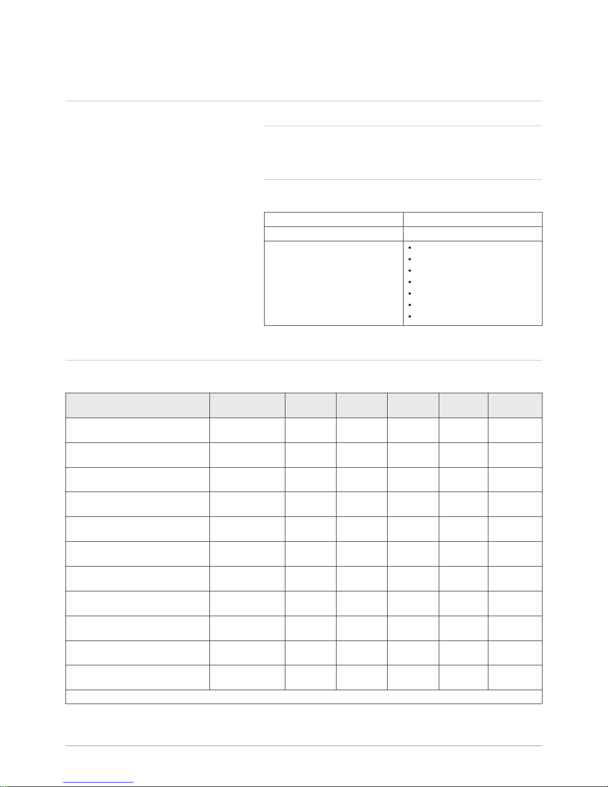
Technical data
Tab.1 General
Boiler speed Unit
POWER
HT+ 1.50
POWER
HT+ 1.70
POWER
HT+ 1.90
POWER HT
+ 1.110
Useful heat output at 80/60°C
Heating mode
Minimum kW 5.0 7.2 9.4 11.4
Useful heat output at 80/60°C
Heating mode
Maximum kW 45 65 85 102
Useful heat output at 50/30 °C
Heating mode
Minimum kW 5.4 7.8 10.2 12.3
Useful heat output at 50/30 °C
Heating mode
Maximum kW 48.6 70.2 91.8 110.2
Heat input Heating mode
Minimum kW 5.1 7.4
9.7
(1)
11.7
Heat input Heating mode
Maximum kW 46.3 66.9 87.4 104.9
Heat input Heating mode
Minimum kW 5.6 8.2 10.7 12.9
Heat input Heating mode
Maximum kW 51.4 74.2 97.0 116.4
Efficiency at 80/60 °C Heating mode under full load
Maximum % 97.4 97.2 97.3 97.2
Efficiency at 50/30 °C -
Heating mode un
der full load
% 105.0 105.0 105.5 105.1
Efficiency - - Return temperature
30°C
Heating mode un
der part load
% 108.4 108.1 108.2 108.1
(1) The heat input with G31 gas is different and is 12.5 kW
3 Technical specifications
10 POWER HT + 7609475 - v04 - 15072015
Page 11
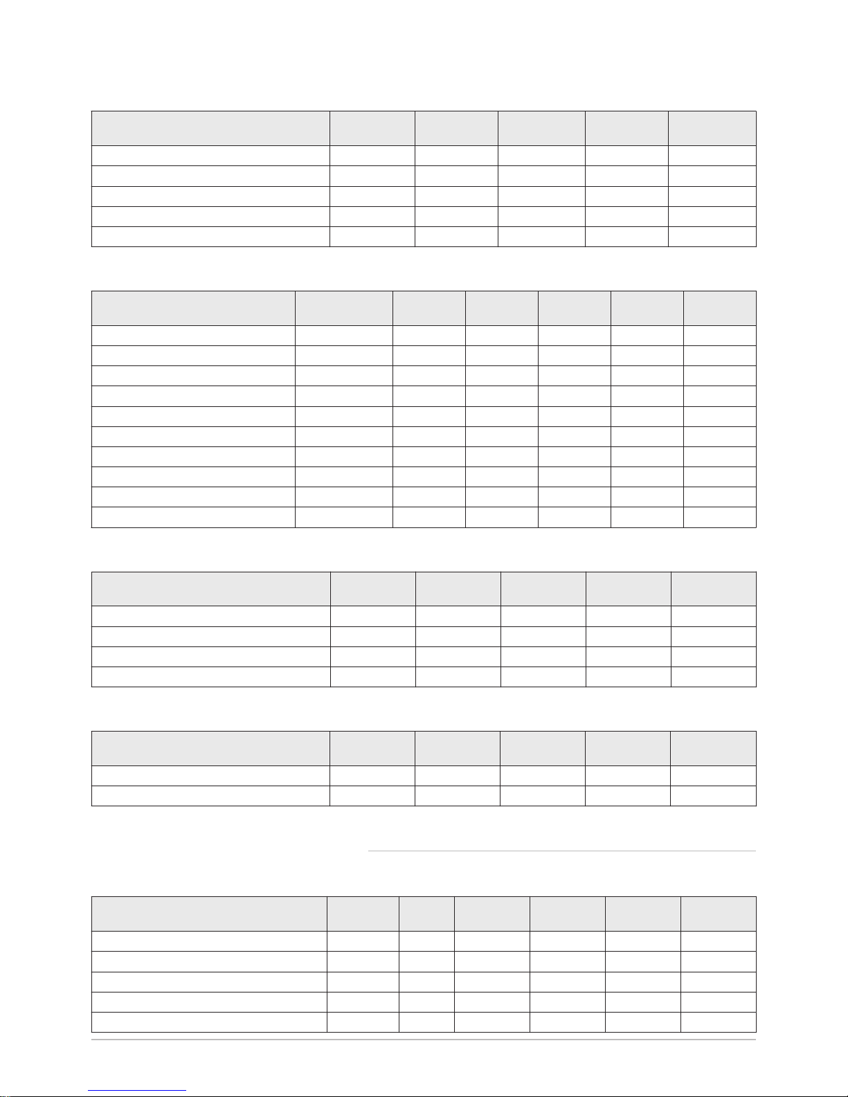
Tab.2 Characteristics of the heating circuit
Unit
POWER HT+
1.50
POWER HT+
1.70
POWER HT+
1.90
POWER HT+
1.110
Water content (excluding expansion vessel) litre 2.81 4.98 8.34 9.83
Minimum operating pressure MPa (bar) 0.05 (0.5) 0.05 (0.5) 0.05 (0.5) 0.05 (0.5)
Maximum operating pressure (MOP) MPa (bar) 0.38 (3.8) 0.38 (3.8) 0.38 (3.8) 0.38 (3.8)
Maximum water temperature °C 85 85 85 85
Maximum operating temperature °C 80 80 80 80
Tab.3 Data on the gases and combustion gases
For gas flow rates at 15°C and
1013.25 hPA
Boiler speed Unit POWER HT
+ 1.50
POWER HT
+ 1.70
POWER HT
+ 1.90
POWER HT
+ 1.110
Consumption of natural gas (G20) Minimum m³/h 0.54 0.78 1.03 1.24
Consumption of natural gas (G20) Maximum m³/h 4.90 7.07 9.25 11.10
Consumption of natural gas (G25) Minimum m³/h 0.63 0.91 1.19 1.44
Consumption of natural gas (G25) Maximum m³/h 5.69 8.22 10.75 12.91
Consumption of Propane (G31) Minimum kg/h 0.40 0.57 0.97 0.91
Consumption of Propane (G31) Maximum kg/h 3.59 5.19 6.79 8.15
NOx emission according to EN297A3 Class 5 mg/kWh 29.8 34.8 39.5 24.7
Flue gas mass flow rate (G20) Minimum kg/h 7.2 14.4 18 18
Flue gas mass flow rate (G20) Maximum kg/h 75.6 111.6 144 169.2
Maximum flue gas temperature Minimum °C 92 76 70 70
Tab.4 Electrical characteristics
Unit POWER HT+
1.50
POWER HT+
1.70
POWER HT+
1.90
POWER HT+
1.110
Power supply voltage VAC 230V 50Hz 230V 50Hz 230V 50Hz 230V 50Hz
Maximum absorbed power - Full load W 100 117 146 185
Maximum absorbed power - Part load W 24 24 24 24
Maximum absorbed power - Stand-by W 2.7 3 3 3
Tab.5 Other characteristics
Unit POWER HT+
1.50
POWER HT+
1.70
POWER HT+
1.90
POWER HT+
1.110
Ingress protection rating IP21 IP21 IP21 IP21
Weight empty kg 60 70 104 109
3.2.1 Other technical parameters
Tab.6 Technical parameters for boiler space heaters
Product name POWER HT
+ 1.50
POWER HT
+ 1.70
POWER HT
+ 1.90
POWER HT
+ 1.110
Condensing boiler Yes Yes Yes Yes
Low-temperature boiler
(1)
No No No No
B1 boiler No No No No
Cogeneration space heater No No No No
Combination heater No No No No
3 Technical specifications
7609475 - v04 - 15072015 POWER HT + 11
Page 12
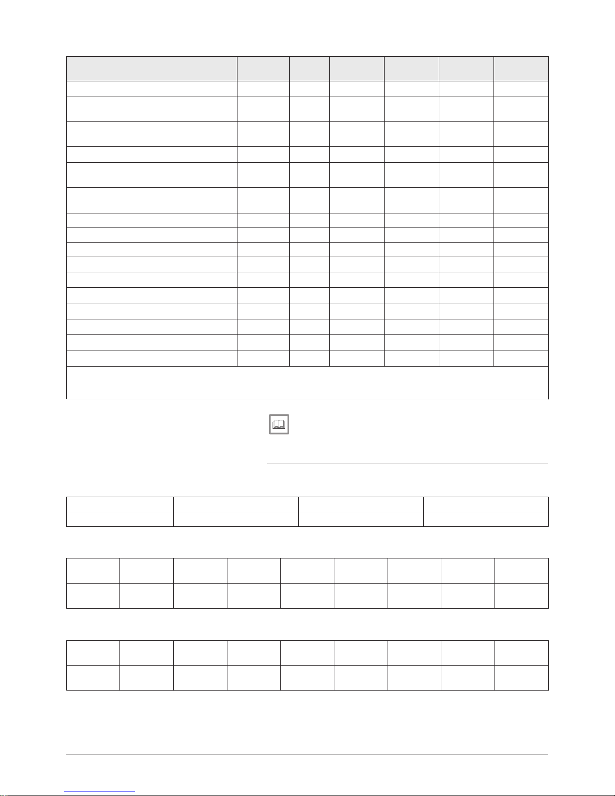
Product name POWER HT
+ 1.50
POWER HT
+ 1.70
POWER HT
+ 1.90
POWER HT
+ 1.110
Rated heat output
Prated
kW 45 65 85 102
Useful heat output at rated heat output
and high temperature regime
(2)
P
4
kW 45.0 65.0 85.0 102.0
Useful heat output at 30% of rated heat
output and low temperature regime
(1)
P
1
kW 15.0 21.7 28.3 34.0
Seasonal space heating energy efficiency
ƞ
s
% 93 93 - -
Useful efficiency at rated heat output and
high temperature regime
(2)
ƞ
4
% 87.7 87.6 87.7 87.6
Useful efficiency at 30% of rated heat
output and low temperature regime
(1)
ƞ
1
% 97.7 97.4 97.5 97.4
Auxiliary electricity consumption
Full load
elmax
kW 0.100 0.117 0.146 0.185
Part load
elmin
kW 0.023 0.024 0.024 0.024
Stand-by
P
SB
kW 0.003 0.003 0.003 0.003
Other characteristics
Standby heat loss
P
stby
kW 0.055 0.059 0.066 0.070
Ignition burner power consumption
P
ign
kW - - - -
Annual energy consumption
Q
HE
GJ 139 201 - -
Sound power level, indoors
L
WA
dB 61 64 - -
Emissions of nitrogen oxides NO
X
mg/kWh 27 31 36 22
(1) Low temperature means for condensing boilers 30°C, for low temperature boilers 37°C and for other heaters 50°C return temperature (at
heater inlet).
(2) High temperature regime means 60°C return temperature at heater inlet and 80°C feed temperature at heater outlet.
See
The back cover for contact details.
3.2.2 Sensor specifications
Tab.7 Heating flow sensor and return sensor
Temperature (in °C) 30 65 85
Resistance (in ohms) 8059 2084 1070
Tab.8 Flue gas sensor
Tempera
ture (in °C)
-50 -10 0 40 100 200 250 300
Resistance
(in ohms)
1 755765 117521 67650 10569 1377 145 65 34
Tab.9 Outside sensor
Tempera
ture (in °C)
-30 -15 -5 0 10 20 30 50
Resistance
(in ohms)
13034 5861 3600 2857 1840 1218 827 407
3 Technical specifications
12 POWER HT + 7609475 - v04 - 15072015
Page 13
4 Description of the product
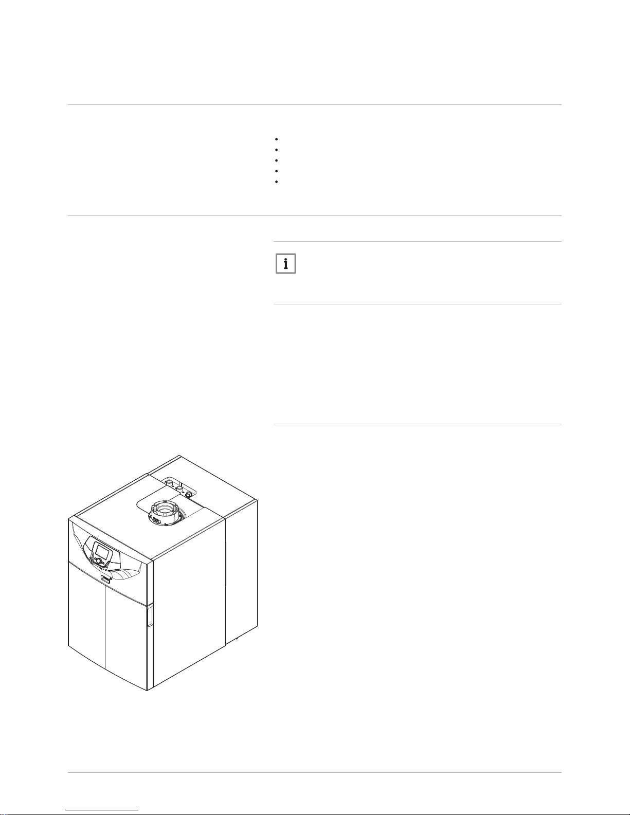
4.1 General description
POWER HT + floor-standing condensing gas boilers have the following
characteristics:
Low pollutant emissions
High efficiency heating
Electronic control panel
Flue gas discharge by a forced flue, chimney or bi-flow type connection.
Perfectly suitable for cascade systems with several boilers.
4.2
Operating principle
4.2.1
Circulation pump
Note
The benchmark for the most efficient circulators is EEI ≤ 0.20.
4.2.2 Gas/air setting
The casing fitted to the boiler is also used as an air box. Air is drawn in by
the fan and gas injected into the Venturi by the fan intake. The fan speed
is modulated according to the settings, the heat demand and the actual
temperatures measured by the temperature sensors. The gas and air are
mixed in the Venturi. The gas/air ratio command function accurately ad
justs the quantities of gas and air required. This provides optimum com
bustion over the entire output range. The gas/air mixture is sent to the
burner, located upstream of the heat exchanger.
4.2.3 Low-loss header (accessory)
The low-loss header is used to prevent interaction between the dynamic
pressures within the boiler and the heating circuits. The low-loss header
considerably reduces the variations in pressure and flow rate caused by
the use of several circulating pumps in an installation and is used to man
age flows in the installation and to control temperatures.
Fig.2 Boiler equipped with the low-loss
header kit
MW-3000144-02
4 Description of the product
7609475 - v04 - 15072015 POWER HT + 13
Page 14
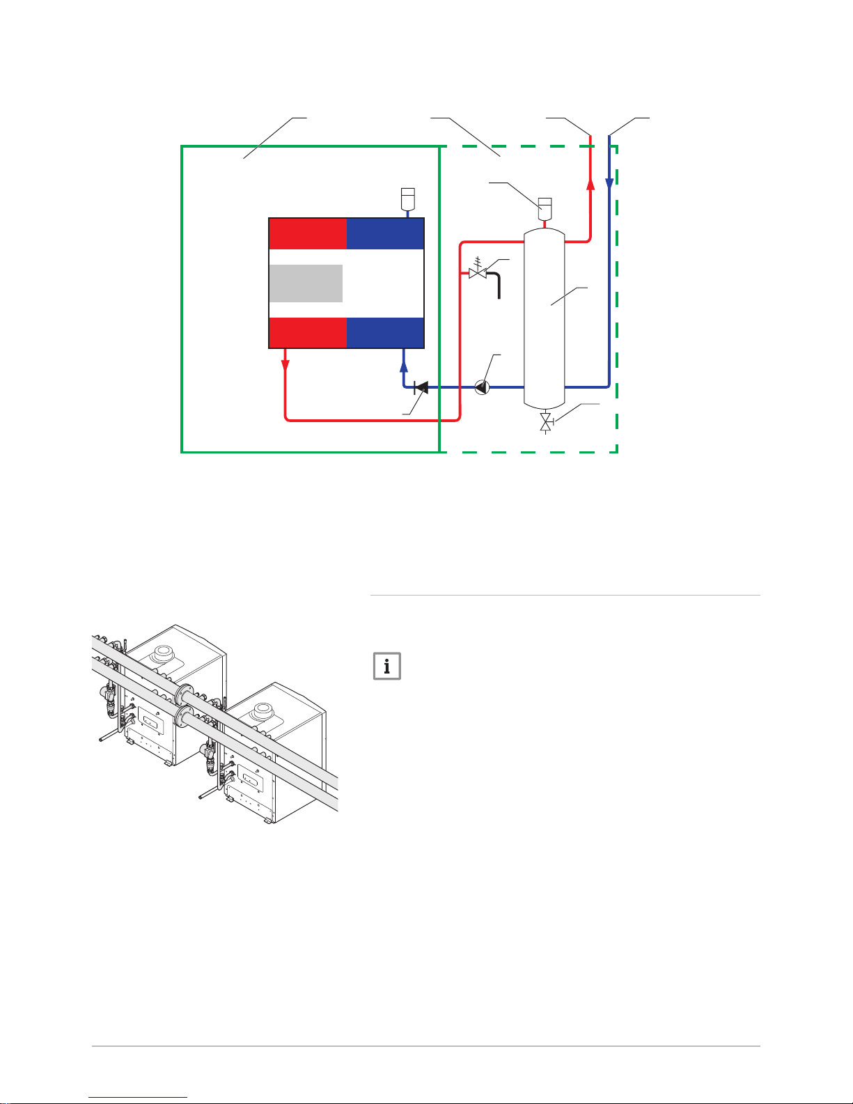
Fig.3 Functional diagram of a boiler with a low-loss header
MW-1000021-06
3
71
5
9
8
62
4
10
1 Boiler
2 Low-loss header kit
3 Low-loss header (accessory)
4 Air vent
5 Drain valve
6 Heating circuit flow
7 Heating circuit return
8 Safety valve
9 Modulating circulating pump
10 Non-return valve
4.2.4 System in cascade
The boiler is ideally suited for a cascade system configuration. Use a boil
er/cascade connection kit to connect boilers in cascade.
Note
Please contact the After Sales Service for further information.
Fig.4 Boilers in cascade
MW-3000145-01
4 Description of the product
14 POWER HT + 7609475 - v04 - 15072015
Page 15
4.2.5 Settings and safety devices
Note
The settings and safety devices are only operational if the boiler is
powered up.
Tab.10 Description of the safety devices
Device Description
Safety thermostats The safety thermostats suspend the supply of gas to the burner if the water in the pri
mary circuit overheats. To resume normal operation of the boiler, eliminate the cause of
this interruption.
Caution
The safety thermostats must in no circumstances be switched off or
disconnected.
NTC flue gas sensor The control panel blocks the gas supply to the burner in the event of overheating. To
resume normal operation of the boiler, switch off the boiler and switch it back on again
with the ON/OFF switch.
Flame detector by ionisation The boiler is put into safety shut-down in the event of gas shortage or incomplete inter
ignition on the burner.
Hydraulic pressure switch Thanks to this device, the burner can only operate if the system pressure is higher than
0.5 bar (0.05 MPa).
When the pressure switch detects a pressure lower than 0.8 bar (0.08 MPa), a warning
message is displayed, without stopping the circulating pump.
Post-circulating pump After the burner stops, depending on the room thermostat setting and if in heating
mode, the circulating pump runs for a further 3 minutes.
Frost protection device When the flow temperature is lower than 5°C, the burner starts up and runs until the
flow temperature reaches 15°C. This device runs under the following conditions:
The boiler is switched on
The gas supply is working
The pressure in the system is higher than 0.5 bar (0,05 MPa)
Anti-blocking of the pump If there are no heating or domestic hot water requirements for 24 consecutive hours, the
pumps start up automatically and run for 10 seconds.
The pumps connected directly to the appliance's terminal blocks are started up every
Friday at 10:00 a.m. and run for 30 seconds.
Anticipatory start-up of the circulat
ing pumps
In heating mode only, the appliance can start up the circulating pumps before burner ig
nition. The duration and activation of anticipatory start-up depends on the conditions of
installation and the operating temperatures. The duration of anticipatory start-up of the
circulating pumps therefore varies from a few seconds to several minutes.
4 Description of the product
7609475 - v04 - 15072015 POWER HT + 15
Page 16
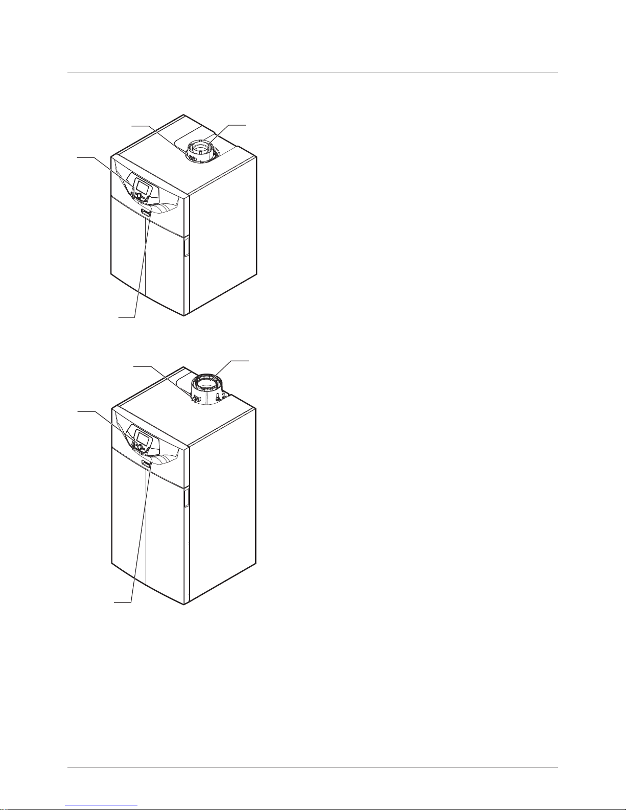
4.3 Main components
1 Control panel
2 Flue gas measuring point
3 Flue gas connection
4 On/Off button
1 Control panel
2 Flue gas measuring point
3 Flue gas connection
4 On/Off button
Fig.5 POWER HT+ 1.50 and POWER HT+
1.70
MW-3000177-01
1
2
3
4
Fig.6 POWER HT+ 1.90 and POWER HT+
1.110
MW-3000178-01
1
2
3
4
4 Description of the product
16 POWER HT + 7609475 - v04 - 15072015
Page 17
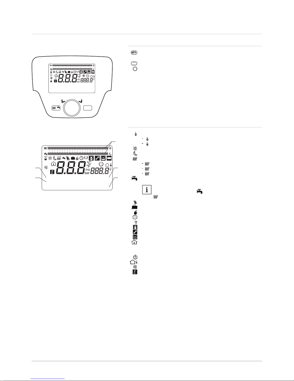
4.4 Control panel description
4.4.1 Description of the keys
Operating mode key
This key is used to access the shortcuts menu
MENU
Menu key
Rotary selection and confirmation button
4.4.2 Description of the symbols
1
2
Burner lit
1
2
(1): Output < 70%
1
2
(2): Output > 70%
Operating mode: Comfort room temperature
Operating mode: Reduced room temperature
1 2 3
Operating mode: Heating
1 2 3
(1): Zone 1 active
1 2 3
(2): Zone 2 active
1 2 3
(3): Zone 3 active
Operating mode: Domestic hot water activated
Note
The domestic hot water can be activated. The heating
1 2 3
is then deactivated.
Sweep Function activated
Holidays program function activated
Operating mode: Manual
Operating mode: Automatic
Data transmission: only when the wireless device is connected.
Error: the burner cannot start up
Error: After Sales Service intervention required
Hydraulic pressure too low
Room temperature (°C)
°C, °F,
bar, PSI
Temperature and hydraulic pressure units: international system or
imperial system.
Protection Mode active: the boiler's frost protection is activated.
Outside temperature (°C)
Solar integration available
Generic error
1 Date: day, month, year
2 Day of the week
3 Boiler / heating circuit pressure
4 Clock: hours and minutes
5 Comfort period indicators over 24 hours in Domestic Hot Water
mode and Heating mode
Fig.7 Control panel keys
MW-3000005
MENU
87654321 9 10 11 12 13 14 15 16 17 18 19 20 21 22 23 24
Fig.8 Symbols on the control panel
4
87654321 9 10 11 12 13 14 15 16 17 18 19 20 21 22 23 24
14:13
1.5 bar
18. February 2014
Tuesday
1
2
3
MW-3000006-GB-05
5
4 Description of the product
7609475 - v04 - 15072015 POWER HT + 17
Page 18
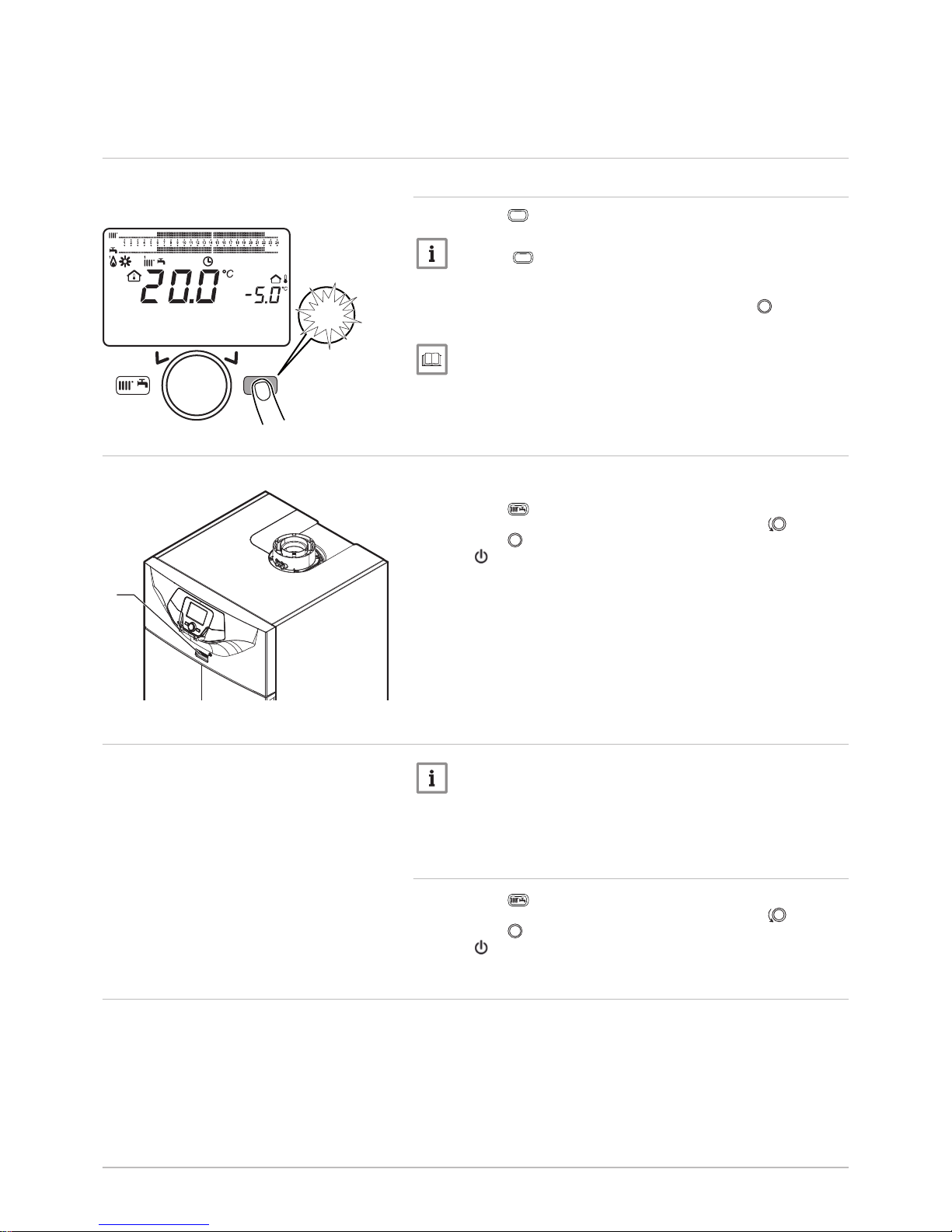
5 Operation
5.1 Use of the control panel
5.1.1 Modifying the user parameters
1. Press the
MENU
key to access the parameters.
Note
Press the
MENU
key to return to the main display.
The user parameters can now be accessed. Use the button to se
lect and modify them.
For more information, see
List of parameters, page 20
5.2
Starting up the boiler
1. Start up the boiler by pressing the ON/OFF switch.
2. Open the gas cock.
3. Press the key to access the shortcuts menu.
4. Select the Standby/operation parameter by turning the button.
5. Press the button to start up the boiler.
The symbol disappears.
5.3 Stopping the boiler
Note
Choose the operating mode Off or Standby.
1. Switch off the boiler by pressing the ON/OFF switch.
2. Close the gas cock.
5.3.1 Putting the boiler in Standby mode
1. Press the key to access the shortcuts menu.
2. Select the Standby/operation parameter by turning the button.
3. Press the button to put the boiler in standby.
The symbol is displayed.
5.4
Frost Protection
The electronic management system of the boiler includes protection
against frost. If the water temperature falls below 5°C, the burner starts up
in order to provide a water temperature of 30°C.
This function only works if the boiler is turned on, the gas supply open and
the hydraulic pressure correct.
Fig.9 Accessing the User parameters
MW-3000052-EN-02
MENU
14:13
1.5 ba
r
18. February 2014
Tuesda
y
MENU
Fig.10 Putting the boiler into operation
MW-3000050
1
5 Operation
18 POWER HT + 7609475 - v04 - 15072015
Page 19

5.4.1 Activating the Off
1. Press the key to access the shortcuts menu.
2. Select the parameter Central heating mode CH1 by turning the
button.
3. Confirm the selection by pressing the button.
4. Select the parameter Off by turning the button.
5. Confirm the selection by pressing the button.
The symbol is displayed.
Note
When the operating mode Off is activated:
The electrical circuits continue to be powered up.
The frost protection function is activated.
Fig.11 Shortcuts menu
MW-3000051-EN-02
Hot water boost
Central heating mode CH1
Room temperature CH1
MENU
5 Operation
7609475 - v04 - 15072015 POWER HT + 19
Page 20
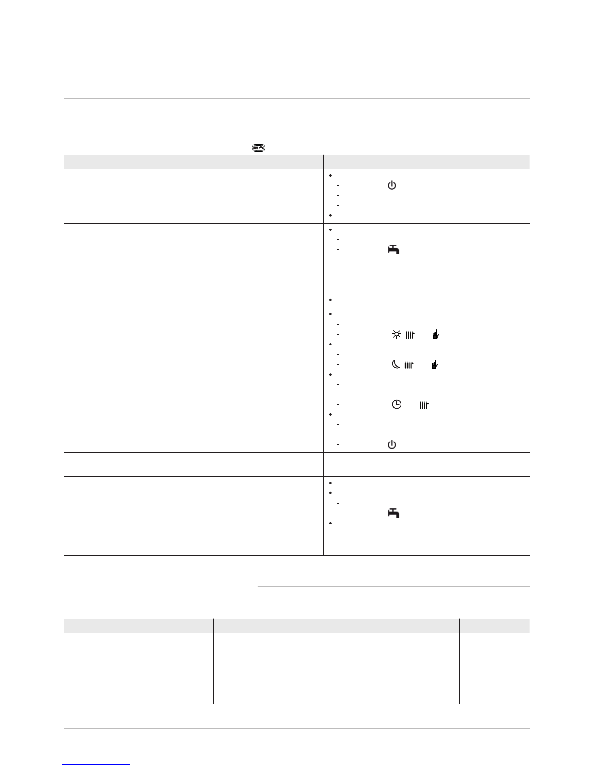
6 Settings
6.1 List of parameters
6.1.1 Shortcuts menu
Tab.11 Functions accessible with the shortcut key
Parameter Description Adjustment range
Standby/operation Boiler standby / start-up Standby : Boiler put on standby.
The symbol is displayed.
The boiler's operating modes are deactivated.
The frost protection function is activated.
On : Putting the boiler into operation
316:Hot water boost Forcing domestic hot water pro
duction.
On :
Activates forcing of domestic hot water.
The symbol is displayed.
If a domestic hot water tank is connected to the
boiler circuit, the boiler will give priority to forcing
heating of the DHW tank, independently of the
other parameters.
Off : Deactivates forcing of domestic hot water.
Central heating mode CH1 Boiler operating mode. On :
Heating is always activated.
The symbols ,
1 2 3
and are displayed.
Reduced :
Heating is deactivated.
The symbols ,
1 2 3
and are displayed.
Timed :
Heating is dependent on the time range program
med.
The symbols and
1 2 3
are displayed.
Off :
The boiler is shut down and frost protection is ac
tive.
The symbol is displayed.
Room temperature CH1 Room temperature set point in
comfort mode.
Hot water heating Setting domestic hot water pro
duction.
On : Enables domestic hot water production.
Off :
Disables domestic hot water production.
The symbol disappears from the display.
Eco : Not used.
Hot water temp setpoint Domestic hot water temperature
set point.
6.1.2 Information menu
Tab.12 Menu Information
Information Description Value
Room temperature Is displayed if the control system unit is configured as a room
temperature appliance
Room temperature min
Room temperature max
Boiler temperature Boiler flow temperature °C
Outside temp Outside temperature °C
6 Settings
20 POWER HT + 7609475 - v04 - 15072015
Page 21
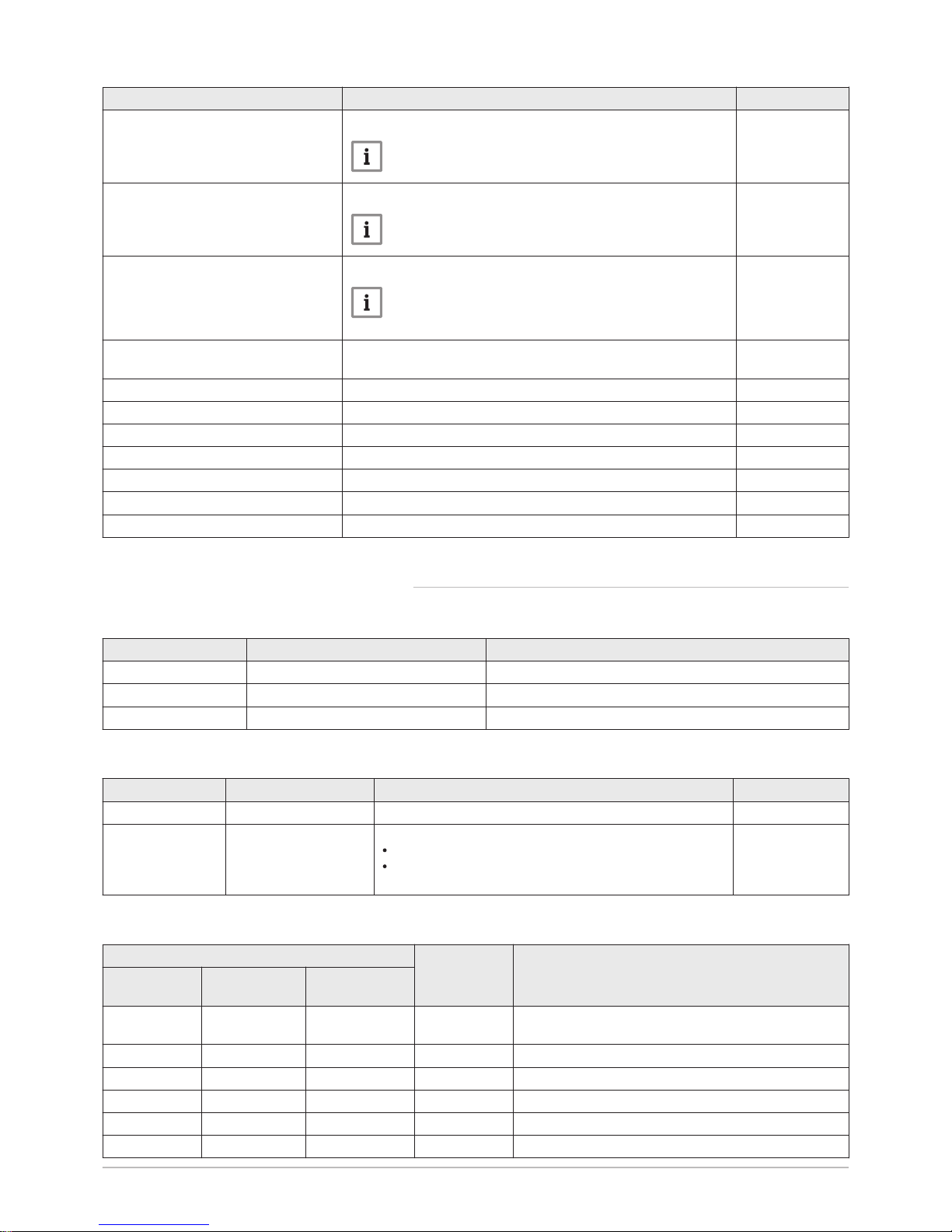
Information Description Value
Outside temp min
Minimum outside temperature value memorised
Note
The outside sensor must be connected.
°C
Outside temp max
Maximum outside temperature value memorised
Note
The outside sensor must be connected.
°C
Hot water temp 1 Domestic hot water temperature
Note
The value displayed comes from the sensor on the
boiler's domestic hot water circuit.
°C
Collector temp 1 Instantaneous temperature of the solar panel sensor (when asso
ciated to a solar system)
°C
State central heating CH1 Operating mode of heating circuit 1
State central heating CH2 Operating mode of heating circuit 2
State central heating CH3 Operating mode of heating circuit 3
State hot water Domestic hot water circuit operating mode
State boiler Boiler operating mode
State solar Indicates solar running (when associated to a solar system) -
Telephone customer service Telephone number of the After Sales Service No.
6.1.3 List of user parameters
Tab.13 Menu Set time and date
Parameter number Parameter Description
1 Hours / minutes Setting the time
2 Day / month Setting the day and the month
3 Year Setting the year
Tab.14 Menu Operator section
Parameter number Parameter Description Factory setting
20 Change Language Setting the interface language English
27 Programming lock Setting the programming lock
Off : the parameters can be displayed and modified
On : the parameters can be displayed but cannot be
modified
Off
Tab.15 Menu Time program
Parameter number Parameter Description
Heating circuit 1Heating circuit 2 Heating circuit 3
500 520 540
Select days
Selecting the days or group of days for the timer pro
gram.
514 534 554 Mon-Sun Selecting a default timer program.
501 521 541 1st Time ON Start of timer period 1.
502 522 542 1st Time OFF End of timer period 1.
503 523 543 2nd Time ON Start of timer period 2.
504 524 544 2nd Time OFF End of timer period 2.
6 Settings
7609475 - v04 - 15072015 POWER HT + 21
Page 22
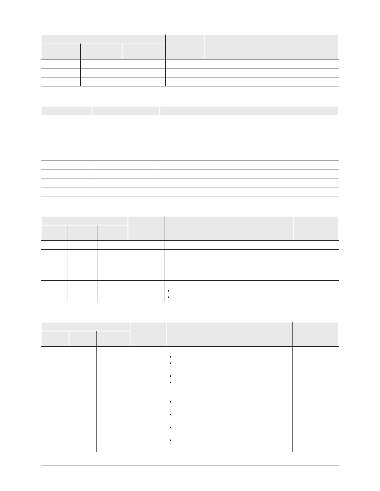
Parameter number Parameter Description
Heating circuit 1Heating circuit 2 Heating circuit 3
505 525 545 3rd Time ON Start of timer period 3.
506 526 546 3rd Time OFF End of timer period 3.
516 536 556 Default values Reset the timer programming parameters (Yes / No)
Tab.16 Menu Time hot water
Parameter number Parameter Description
560 Select days Selecting the days or group of days for the timer program.
574 Mon-Sun Selecting a default timer program.
561 1st Time ON Start of timer period 1.
562 1st Time OFF End of timer period 1.
563 2nd Time ON Start of timer period 2.
564 2nd Time OFF End of timer period 2.
565 3rd Time ON Start of timer period 3.
566 3rd Time OFF End of timer period 3.
576 Default values Reset the timer programming parameters (Yes / No).
Tab.17 Menu Holiday Settings
Parameter number Parameter Description Factory setting
Heating
circuit 1
Heating
circuit 2
Heating cir
cuit 3
641 651 661 Select Selecting the holiday period Period 1
642 652 662
Start
Selecting the day and month of the start of the current
holiday period.
643 653 663
End
Selecting the day and month of the end of the current
holiday period.
648 658 668
Operating
level
Boiler operating mode during the holiday period.
Off
Reduced
Off
Tab.18 Menu Temps / mode CH1 – Temps / mode CH2 – Temps / mode CH3
Parameter number Parameter Description Factory setting
Heating
circuit 1
Heating
circuit 2
Heating cir
cuit 3
700 1000 1300
Operating
mode
The control unit is installed on the boiler:
Off : heating is deactivated.
Timed : heating is dependent on the timer pro
gram.
Reduced : heating is in permanent reduced mode.
On : heating is in permanent comfort mode.
The control unit is installed as a room temperature
control system:
Off : the boiler starts up when the room tempera
ture falls below the frost protection set point.
Timed : heating is dependent on the timer pro
gram.
Reduced : the room temperature set point is the
reduced set point (parameters 712, 1010, 1310)
On : the room temperature set point is the comfort
set point (parameters 710, 1010, 1310)
On
6 Settings
22 POWER HT + 7609475 - v04 - 15072015
Page 23
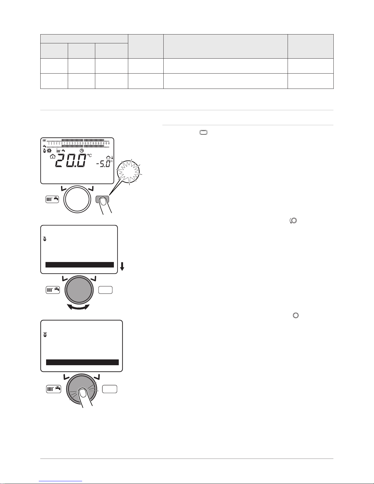
Parameter number Parameter Description Factory setting
Heating
circuit 1
Heating
circuit 2
Heating cir
cuit 3
710 1010 1310 Comfort
setpoint
20°C
712 1012 1310 Reduced
temp setpoint
16°C
6.2
Setting the parameters
6.2.1 Setting the date and time
1. Press the
MENU
key to access the parameters.
2. Select the Set time and date menu by turning the button.
3. Confirm the menu selection by pressing the button .
The parameter Hours / minutes appears.
Fig.12 Access to parameters
MW-3000052-EN-02
MENU
14:13
1.5 ba
r
18. February 2014
Tuesda
y
MENU
Fig.13 Menu selection
MENU
---------------------------------------------------
-
Information
Set time and date
MW-3000053-EN-02
Fig.14 Time / Date parameter
MENU
Information
Set time and date
Operator section
MW-3000054-EN-02
6 Settings
7609475 - v04 - 15072015 POWER HT + 23
Page 24
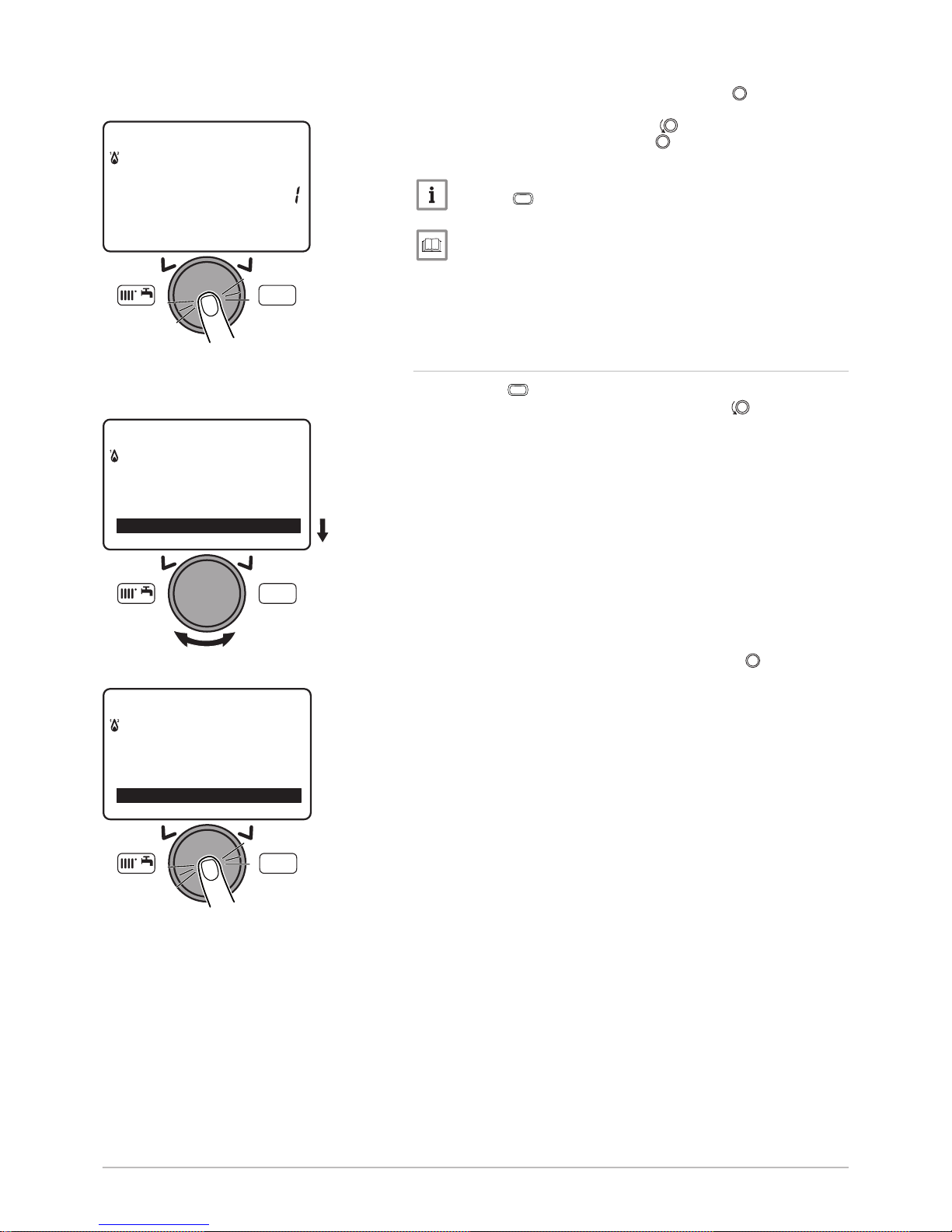
4. Confirm the parameter selection by pressing the button.
The parameter flashes, it can be modified.
5. Modify the parameter by turning the button.
6. Confirm the setting by pressing the button.
7. Set the other settings parameters if necessary.
Note
Press the
MENU
key to return to the main display.
For more information, see
List of user parameters, page 21
6.2.2
Language Selection
1. Press the
MENU
key to access the parameters.
2. Select the Operator section menu by turning the button.
3. Confirm the menu selection by pressing the button .
The Change Language parameter appears.
Fig.15 Modification possible prior to confir
mation
MENU
12:00Hours / minutes
Set time and date
MW-3000055-EN-02
Fig.16 Selecting the Info Menu
MW-3000056-EN-02
MENU
---------------------------------------------------
-
Information
Set time and date
Fig.17 Selecting the User Interface parame
ter
MW-3000057-EN-02
MENU
Set time and date
Operator section
Time central heating CH1
6 Settings
24 POWER HT + 7609475 - v04 - 15072015
Page 25
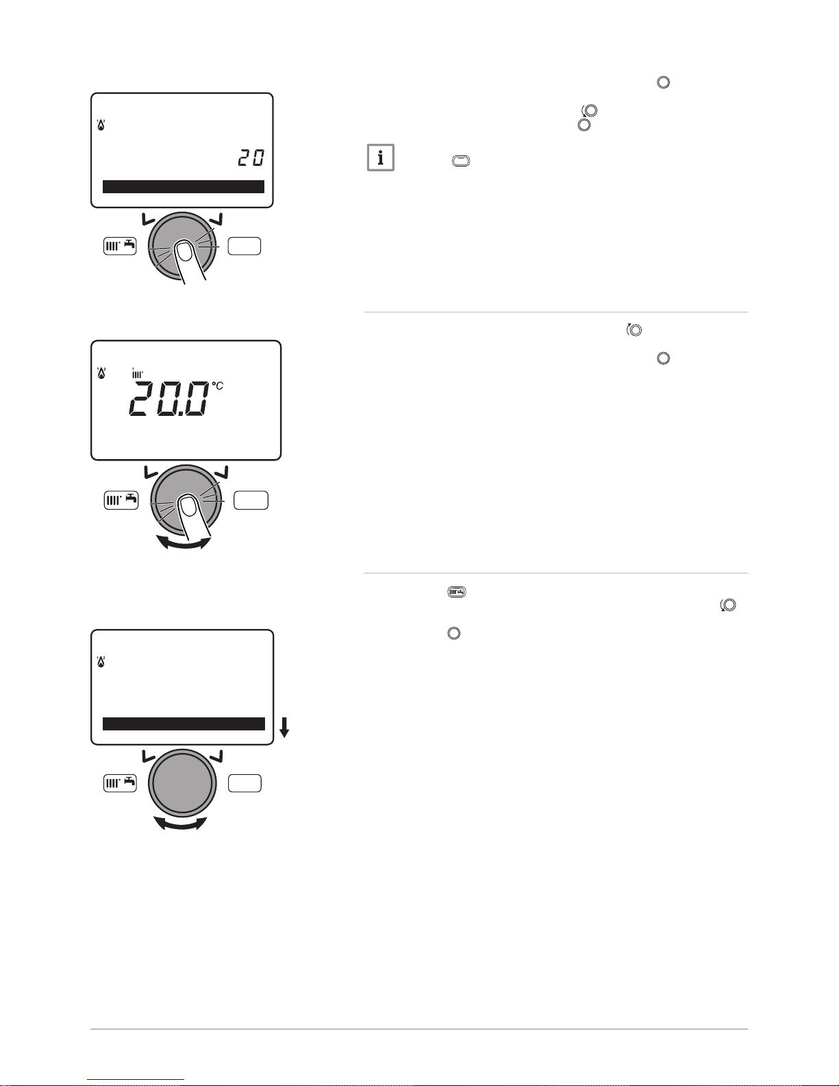
4. Confirm the menu selection by pressing the button .
The language currently used flashes.
5. Modify the parameter by turning the button.
6. Confirm the setting by pressing the button.
Note
Press the
MENU
key to return to the main display.
6.2.3 Setting a temporary heating flow temperature
1. From the control panel main screen, turn the button to increase
or reduce the temperature value.
2. Confirm the menu selection by pressing the button .
6.2.4 Changing the operating mode
1. Press the key to access the shortcuts menu.
2. Select the parameter Central heating mode CH1 by turning the
button.
3. Press the button to confirm.
Fig.18 Selecting the Language parameter
MW-3000058-EN-02
MENU
English
O
p
erator section
Change language
Fig.19 Confirming the selected temperature
MW-3000143-EN-02
MENU
Temporary setpoin
t
Fig.20 Selecting the Regime CH1 parame
ter
MW-3000059-EN-02
MENU
---------------------------------------------------
-
Standby/operation
Hot water boost
6 Settings
7609475 - v04 - 15072015 POWER HT + 25
Page 26
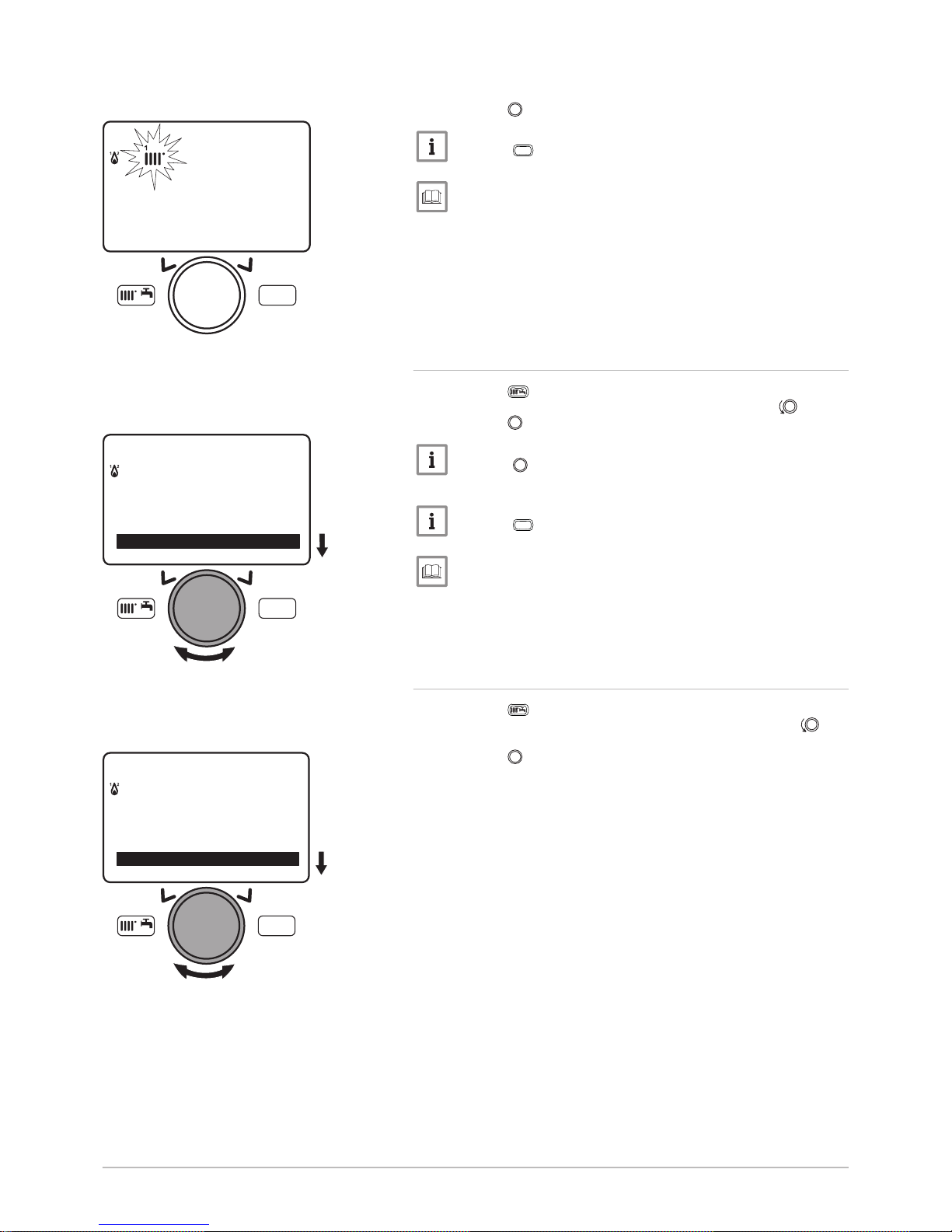
4. Select the appropriate operating mode.
5. Press the button to confirm.
Note
Press the
MENU
key to return to the main display.
For more information, see
Shortcuts menu, page 20
6.2.5 Forcing domestic hot water production
1. Press the key to access the shortcuts menu.
2. Select the parameter 316:Hot water boost by turning the button.
3. Press the button to start forcing domestic hot water.
Note
Press the button a second time to stop forcing domestic hot
water.
Note
Press the
MENU
key to return to the main display.
For more information, see
Shortcuts menu, page 20
6.2.6 Setting the room temperature set point (Onmode)
1. Press the key to access the shortcuts menu.
2. Select the parameter Room temperature CH1 by turning the but
ton.
3. Press the button to confirm.
Fig.21 Confirming the operating mode se
lected
MW-3000060-EN-02
MENU
Timed
Central heatin
g mode CH1
Settin
g NOT confirmed
Fig.22 Parameter selection 316:Hot water
boost
MW-3000061-EN-02
MENU
---------------------------------------------------
-
Standby/operation
Hot water boost
Fig.23 Selecting the parameter Room
temperature CH1
MW-3000062-EN-02
MENU
---------------------------------------------------
-
Standby/operation
Hot water boost
6 Settings
26 POWER HT + 7609475 - v04 - 15072015
Page 27
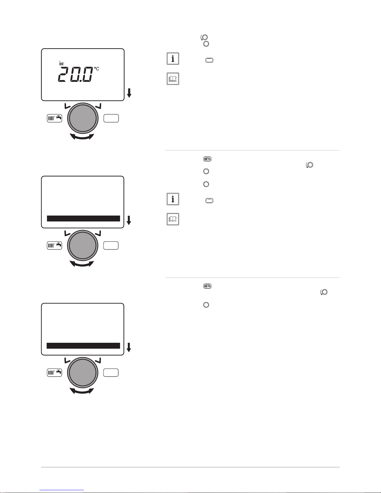
4. Turn the button to modify the temperature set point.
5. Press the button to confirm.
Note
Press the
MENU
key to return to the main display.
For more information, see
Shortcuts menu, page 20
6.2.7
Modifying the domestic hot water production mode
1. Press the key to access the shortcuts menu.
2. Select the parameter Hot water heating by turning the button.
3. Press the button to confirm.
4. Select the appropriate operating mode.
5. Press the button to confirm.
Note
Press the
MENU
key to return to the main display.
For more information, see
Shortcuts menu, page 20
6.2.8
Setting the domestic hot water temperature set point
1. Press the key to access the shortcuts menu.
2. Select the parameter Hot water temp setpoint by turning the but
ton.
3. Press the button to confirm.
Fig.24 Modification of the temperature set
point
MW-3000063-EN-02
MENU
Room temperature CH1
Fig.25 Selecting the parameter Hot water
heating
MW-3000064-EN-02
MENU
Room temperature CH3
Hot water mode
Hot water temp setpoint
Fig.26 Selecting the parameter Hot water
temp setpoint
MW-3000066-EN-02
MENU
Hot water mode
Hot water temp setpoint
---------------------------------------------------
-
6 Settings
7609475 - v04 - 15072015 POWER HT + 27
Page 28
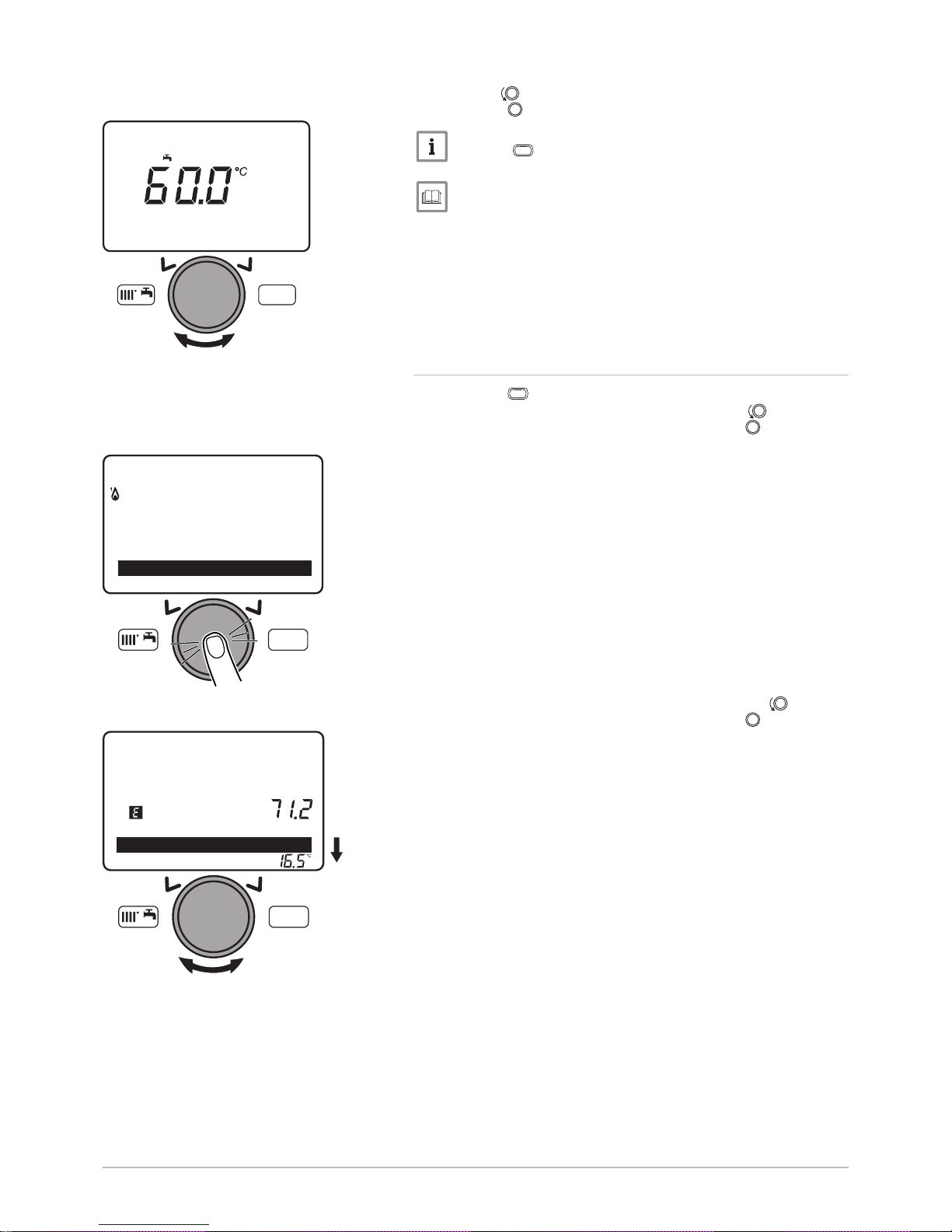
4. Turn the button to modify the temperature set point.
5. Press the button to confirm.
Note
Press the
MENU
key to return to the main display.
For more information, see
Shortcuts menu, page 20
6.2.9
Setting the room temperature set point (Reduced mode)
1. Press the
MENU
key to access the parameters.
2. Select the Temps / mode CH1 menu by turning the button.
3. Confirm the menu selection by pressing the button .
The parameter Operating mode appears.
4. Select the Reduced temp setpoint menu by turning the button.
5. Confirm the menu selection by pressing the button .
The room temperature set point (Reducedmode) flashes.
Fig.27 Modification of the temperature set
point
MW-3000067-EN-02
MENU
Hot water temp setpoint
Fig.28 Selecting the menu Temps / mode
CH1
MW-3000068-EN-03
MENU
Holiday heating CH1
Temps / mode CH1
---------------------------------------------------
-
Fig.29 Selecting the menu Reduced temp
setpoint
MW-3000129-EN-02
MENU
Temps / mode CH1
Reduced temp setpoint
6 Settings
28 POWER HT + 7609475 - v04 - 15072015
Page 29
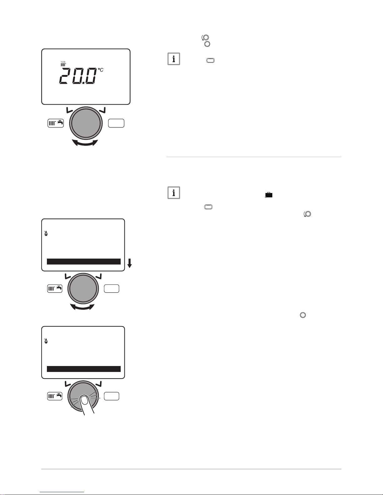
6. Turn the button to modify the temperature set point.
7. Press the button to confirm.
Note
Press the
MENU
key to return to the main display.
6.2.10
Programming a Holiday period
This series of functions is used to program the boiler's behaviour in holiday
periods or during prolonged absences. The various parameters are used
to program one of eight Holiday periods.
Note
When the function is activated, the symbol is displayed.
1. Press the
MENU
key to access the parameters.
2. Select the Holiday heating CH1 menu by turning the button.
3. Confirm the menu selection by pressing the button .
The Select parameter appears.
Fig.30 Modification of the temperature set
point
MW-3000070-EN-03
MENU
Reduced temp setpoint
Fig.31 Menu selection Holiday heating CH1
MW-3000071-EN-02
MENU
---------------------------------------------------
-
Information
Set time and date
Fig.32 Confirming the menu Holiday heating
CH1
MW-3000072-EN-02
MENU
Time hot water
Holiday heating CH1
Temps / mode CH1
6 Settings
7609475 - v04 - 15072015 POWER HT + 29
Page 30
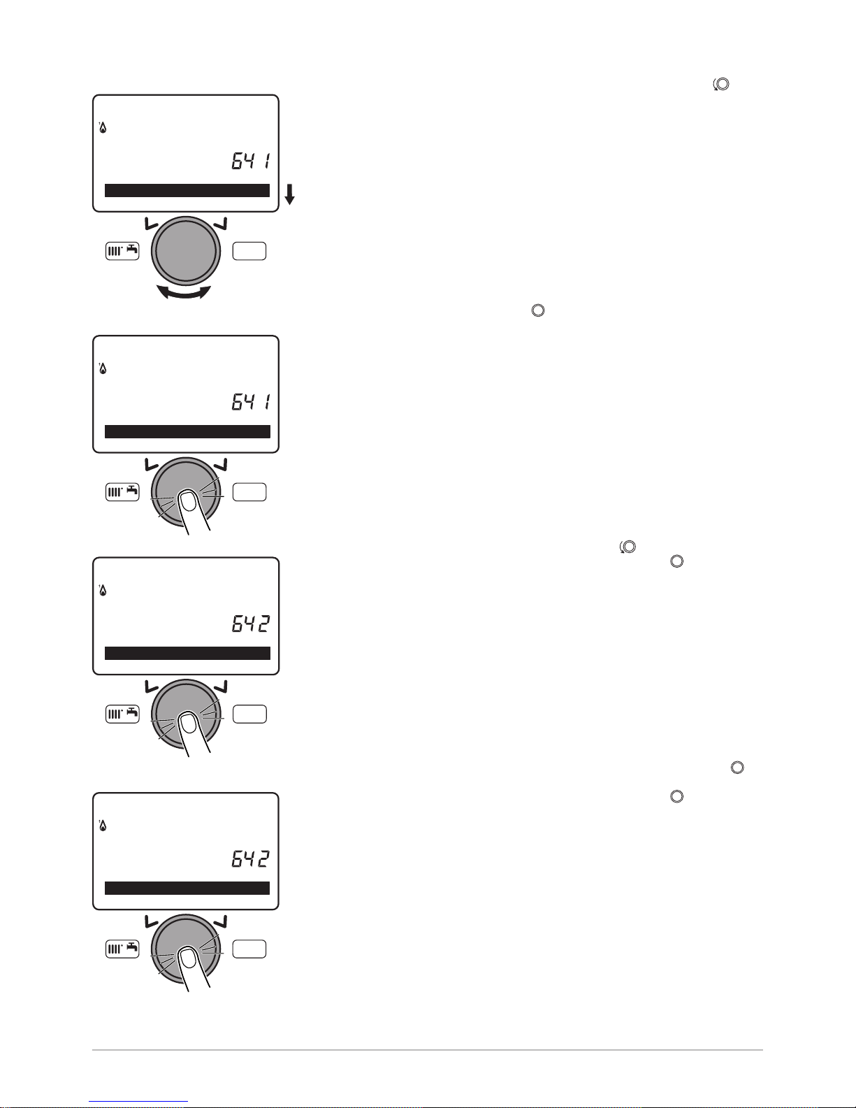
4. Select the Holiday period to be programmed by turning the but
ton.
5. Confirm by pressing the button.
6. Select the Start parameter by turning the button.
7. Confirm the menu selection by pressing the button .
8. Select and confirm the start date of the holiday period with the
button.
9. Confirm the menu selection by pressing the button .
Fig.33 Selecting the holiday period
MW-3000073-EN-02
MENU
Period 1
Holida
y
heating CH1
Preselection
Fig.34 Confirming the holiday period selec
ted
MW-3000074-EN-02
MENU
Period 1
Holida
y
heating CH1
Preselection
Fig.35 Confirming the period selected
MW-3000075-EN-02
MENU
- - / - -Day / month
Holida
y
heating CH1
Period 1: Start
Fig.36 Confirming the start date of the holi
day period
MW-3000076-EN-02
MENU
- - / - -Day / month
Holida
y
heating CH1
Period 1: Start
6 Settings
30 POWER HT + 7609475 - v04 - 15072015
Page 31
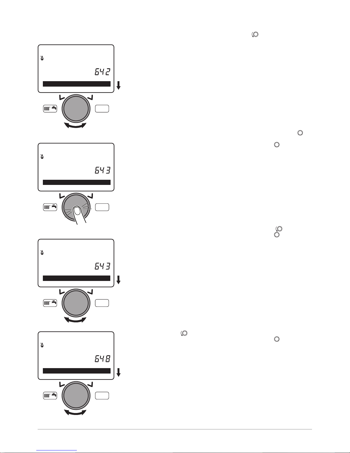
10. Select the End parameter by turning the button.
11. Select and confirm the end date of the holiday period with the
button.
12. Confirm the menu selection by pressing the button .
13. Select the Operating level parameter by turning the button.
14. Confirm the menu selection by pressing the button .
15. Select the boiler's operating mode during the holiday period by turn
ing the button.
16. Confirm the menu selection by pressing the button .
Fig.37 Selecting the end date of the holiday
period
MW-3000077-EN-02
MENU
25/06Day / month
Holida
y
heating CH1
Period 1: Start
Fig.38 Confirming the end date of the holi
day period
MW-3000078-EN-02
MENU
- - / - -Day / month
Holida
y
heating CH1
Period 1: End
Fig.39 Selecting the parameter Operating
level
MW-3000079-EN-02
MENU
15/08Day / month
Holida
y
heating CH1
Period 1: End
Fig.40 Selecting the operating mode
MW-3000080-EN-02
MENU
Of
f
Holiday heating CH1
Operating level
6 Settings
7609475 - v04 - 15072015 POWER HT + 31
Page 32
For more information, see
Setting the room temperature set point (Onmode), page 26
Setting the room temperature set point (Reduced mode), page 28
Activating the Off, page 19
6.2.11 Selecting a heating circuit
The control panel can manage up to three different heating circuits.
1. From the home screen, turn the button to select one of the three
heating circuits available.
2. Press the button to confirm.
3. Turn the button to temporarily modify the temperature set point
on the selected heating circuit.
4. Press the button to confirm.
The selected heating circuit is active.
6.3
Accessing the information menu
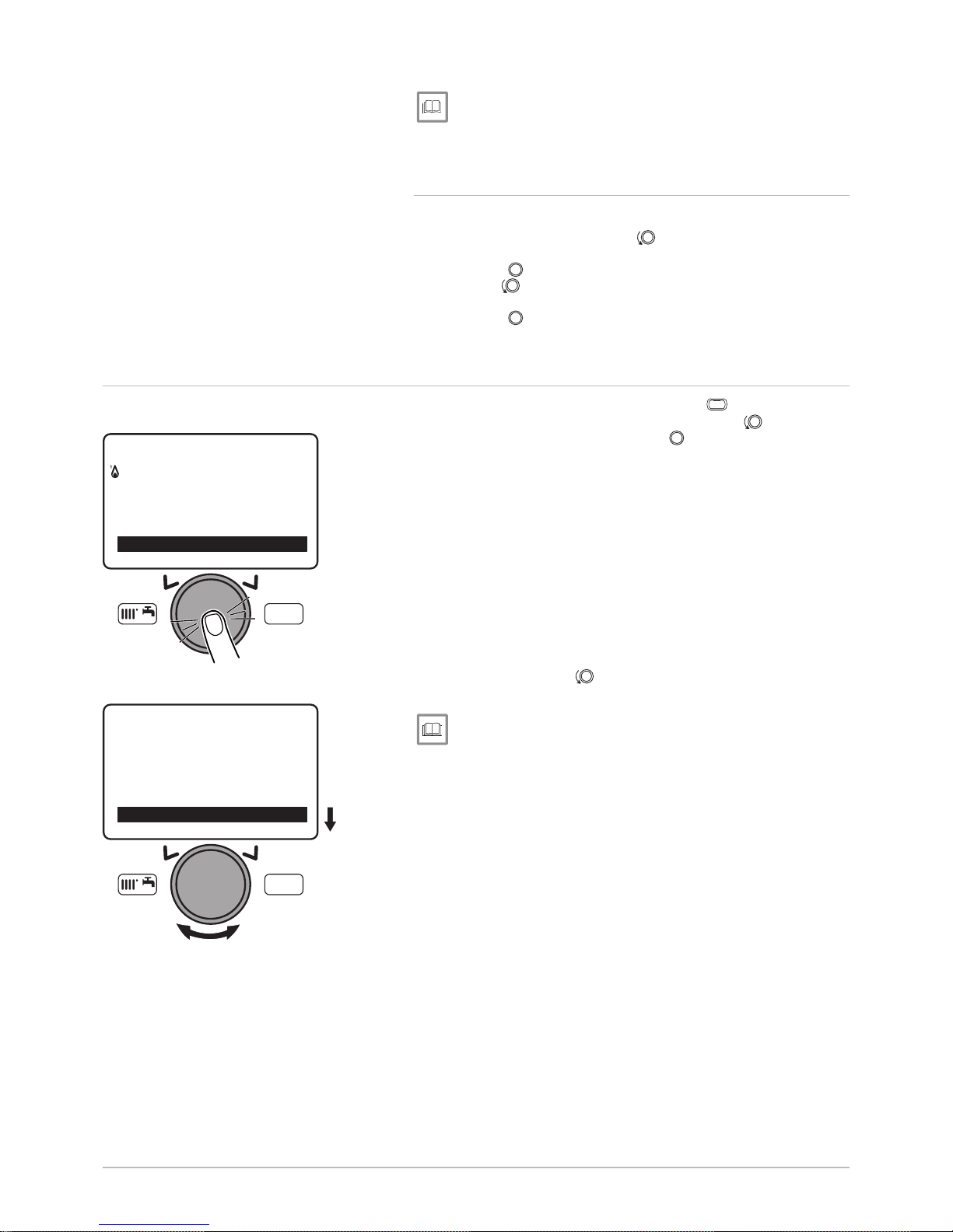
1. Go to the parameters menu by pressing the
MENU
key.
2. Select the Information menu with the rotary button .
3. Confirm by pressing the rotary button .
4. Use the rotary button to scroll through the various items of infor
mation.
For more information, see
Information menu, page 20
Fig.41 Selecting the menu Information
MW-3000098-EN-02
MENU
---------------------------------------------------
-
Information
Set time and date
Fig.42 Selecting the various items of infor
mation
MW-3000099-EN-02
MENU
49.0 °C
Information
Boiler temperature
6 Settings
32 POWER HT + 7609475 - v04 - 15072015
Page 33

7 Maintenance
7.1 General
We recommend having the boiler inspected and serviced at regular inter
vals.
Boiler maintenance and cleaning must be carried out at least once a
year by a qualified professional.
Have an inspection carried out and the flues swept at least once a year
or more, depending on the regulations in force in your country.
Caution
Failure to service the appliance voids the warranty.
Caution
Maintenance work must be carried out by a qualified professional.
Caution
Only genuine spare parts may be used.
7 Maintenance
7609475 - v04 - 15072015 POWER HT + 33
Page 34
8 Troubleshooting
8.1 Error codes
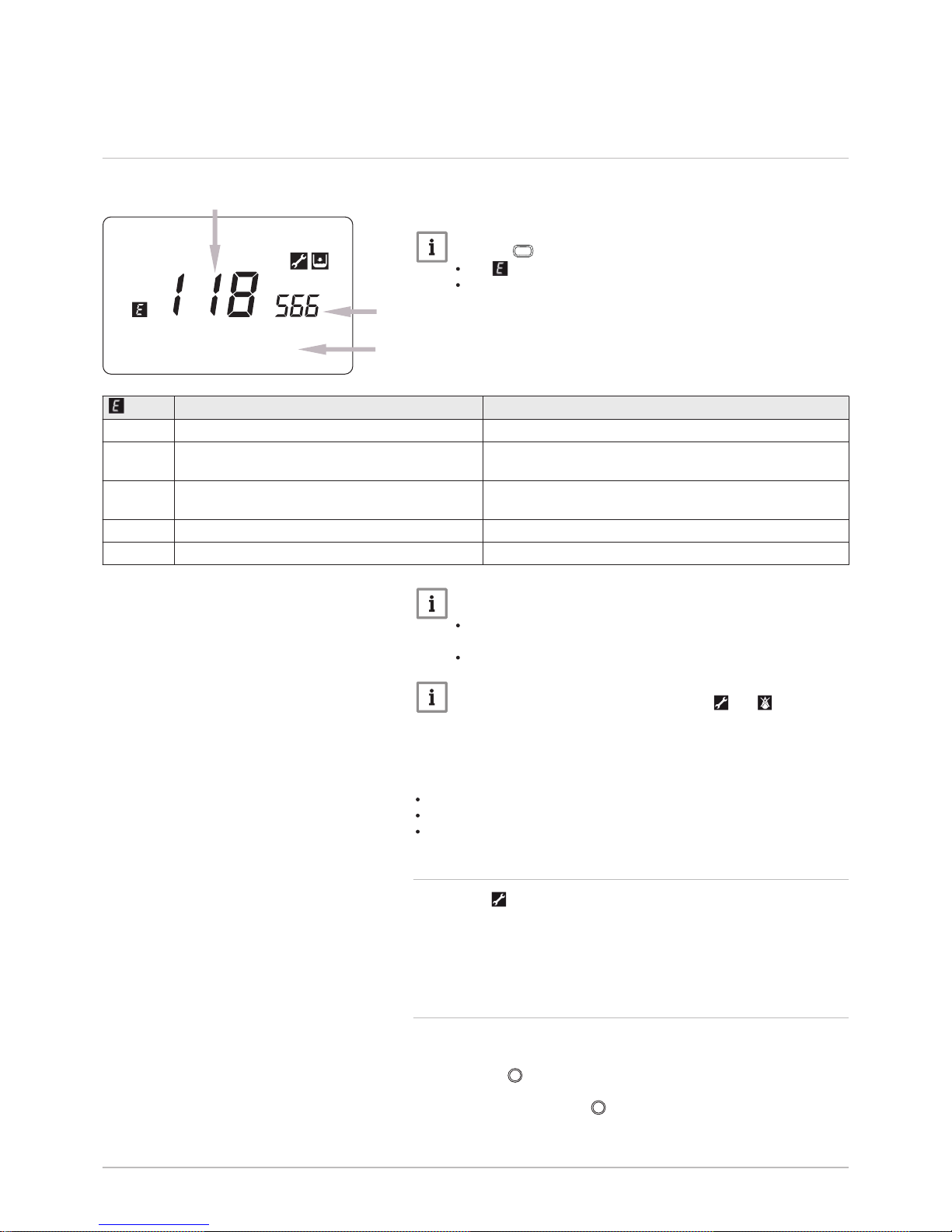
A Error code
B Secondary error code
C Description of the error
Note
Press the
MENU
key to return to the main display.
The symbol continues to be displayed on the control panel.
If the error is not resolved after one minute, the error code is
displayed on the control panel a second time.
Tab.19 List of error codes
Display Description of the error
10 10:Outside sensor Outside temperature sensor.
50 50:HW sensor 1 Domestic hot water sensor (only for heating only models with
domestic hot water tank).
110 110:Lockout SLT Safety thermostat cut-off for overheating (pump blocked or
air in the heating circuit).
111 111:Shutdown limit thermost Safety thermostat cut-off for overheating.
133 133:Safety time exceeded Ignition error (4 attempts).
Note
Contact the installer:
If an error code different from the ones described is displayed
on the screen
If an error code is displayed on a regular basis
Note
If the error code simultaneously displays the and symbols,
contact the accredited technical assistance service.
Code E110
The code E110 is displayed when overheating occurs due to a breach in
the insulation:
Remove the heat exchanger.
Replace the insulation behind the burner bracket.
Replace the safety thermofuse behind the heat exchanger.
8.1.1 Automatic error code clearing
If the symbol is displayed at the same time as the error code, the error
code is automatically cleared when the cause that prompted it stops.
A flow or return temperature in excess of the critical value prompts an er
ror code. The error code is automatically cleared when the temperature
drops below the critical value.
8.1.2 Clearing error codes
If the probable cause of an error code is resolved but the error code con
tinues to be displayed, proceed as follows to clear the error code:
1. Press the button.
The command Reset? Yes is displayed on the control panel.
2. Confirm by pressing the button.
The error code disappears after a few seconds.
Fig.43 Error code
Error
118: Water pressure too low
0,4 bar
BM-0000026-GB-03
A
B
C
8 Troubleshooting
34 POWER HT + 7609475 - v04 - 15072015
Page 35

9 Environmental
9.1 Energy savings
Tips on saving energy:
Keep the room in which the boiler is installed well ventilated.
Do not block ventilation outlets.
Do not cover the radiators. Do not hang curtains in front of the radiators.
Install reflective panels behind the radiators to prevent heat losses.
Insulate the pipes in rooms that are not heated (cellars and lofts).
Turn off the radiators in rooms not being used.
Do not run hot (or cold) water pointlessly.
Install a water-saving shower head to save up to 40% energy.
Take showers rather than baths. A bath consumes twice as much water
and energy.
9.2
Room thermostat and settings
Various models of room thermostat are available. The type of thermostat
used and the parameter selected impact total energy consumption.
A modulating regulator, which may be combined with thermostatic
valves, is eco-friendly in terms of energy and offers an excellent level of
comfort. This combination allows you to set the temperature separately
for each room. However, do not install thermostatic radiator valves in the
room in which the room thermostat is located.
Complete opening and closing of the thermostatic radiator valves cau
ses undesirable variations in temperature. Therefore, these must be
opened/closed progressively.
Set the room thermostat to a temperature of approximately 20°C to re
duce heating costs and energy consumption.
Lower the thermostat setting to approximately 16°C at night or when you
are not at home. This reduces heating costs and energy consumption.
Lower the thermostat setting well before airing the rooms.
Set the water temperature to a lower level in summer than in winter (e.g.
60°C and 80°C respectively) when an ON/OFF thermostat
is used.
When clock thermostats and programmable thermostats are to be set,
do not forget to take any holidays and days when no one is at home into
account.
9 Environmental
7609475 - v04 - 15072015 POWER HT + 35
Page 36

10 Disposal
10.1 Disposal and Recycling
Warning
Removal and disposal of the boiler must be carried out by a quali
fied installer in accordance with local and national regulations.
If you need to remove the boiler, proceed as follows:
1. Switch off the boiler.
2. Cut the electrical power to the boiler.
3. Close the main gas valve.
4. Close the water mains.
5. Close the gas valve on the boiler.
6. Drain the installation.
7. Remove the air vent hose above the siphon.
8. Remove the siphon.
9. Remove the air/flue gas pipes.
10. Disconnect all pipes on the underside of the boiler.
11. Dismantle the boiler.
Fig.44 Recycling
MW-3000179-03
10 Disposal
36 POWER HT + 7609475 - v04 - 15072015
Page 37

11 Warranty
11.1 General
We would like to thank you for buying one of our appliances and for your
trust in our product.
In order to ensure continued safe and efficient operation we recommend
that the product is regularly inspected and maintained.
Your installer and our service department can assist with this.
11.2
Terms of warranty
The following provisions do not affect the application, in favour of the buy
er, of the legal provisions with regard to hidden defects that are applicable
in the buyer's country.
This appliance comes with a warranty that covers all manufacturing faults;
the warranty period will commence on the date of purchase stated on the
installer's invoice.
The duration of our warranty is shown on the certificate delivered with the
appliance.
The warranty period is stated in our price list.
As a manufacturer, we can by no means be held liable if the appliance is
used incorrectly, is poorly maintained or not maintained at all, or is not in
stalled correctly (it is your responsibility to ensure that installation is carried
out by a qualified installer).
In particular, we cannot be held liable for material damage, intangible los
ses or physical injury resulting from an installation that does not comply
with:
Legal or regulatory requirements or provisions laid down by the local au
thorities,
National or local regulations and special provisions relating to the instal
lation,
Our manuals and installation instructions, in particular in terms of regular
maintenance of the appliances,
Our warranty is limited to the replacement or repair of the parts found to
be defective by our technical services team, excluding labour, transfer and
transport costs.
Our warranty does not cover replacement or repair costs for parts that may
become defective due to normal wear, incorrect usage, the intervention of
unqualified third parties, inadequate or insufficient supervision or mainte
nance, a mains supply that is not appropriate or the use of unsuitable or
poor quality fuel.
Smaller parts, such as motors, pumps, electrical valves etc., are guaran
teed only if these parts have never been dismantled.
The rights established in European Directive 99/44/EEC, implemented by
legal decree No. 24 of 2 February 2002 and published in Official Journal
No. 57 of 8 March 2002, remain in force.
11 Warranty
7609475 - v04 - 15072015 POWER HT + 37
Page 38
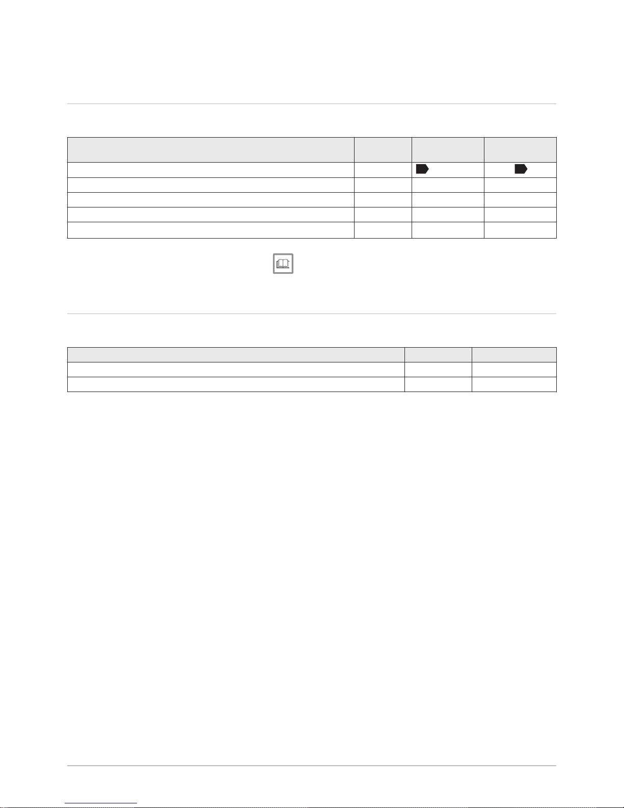
12 Appendix
12.1 Product fiche - Boiler space heaters
Tab.20 Product fiche for boiler space heaters
Brand name - Product name POWER HT+
1.50
POWER HT+
1.70
Seasonal space heating energy efficiency class
A
A
Rated heat output
(Prated or Psup)
kW 45 65
Seasonal space heating energy efficiency % 93 93
Annual energy consumption GJ 139 201
Sound power level LWA indoors dB 61 64
See
For specific precautions on assembly, installation and mainte
nance: see the chapter on Safety Instructions.
12.2
Product fiche - Temperature Controls
Tab.21 Product fiche for temperature controls
Baxi - POWER HT + HMI text
Class II
Contribution to space heating energy efficiency % 2
12 Appendix
38 POWER HT + 7609475 - v04 - 15072015
Page 39
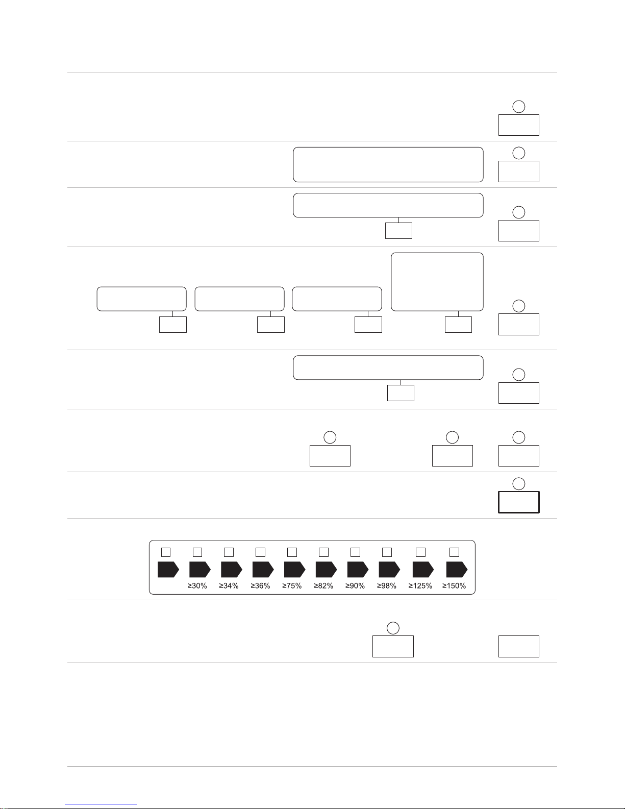
12.3 Package fiche
Fig.45 Package fiche for boilers indicating the space heating energy efficiency of the package
AD-3000743-01
%
1
‘I’
2
%+
3
%( - ‘I’ ) x 0.1 = ±
4
%(‘III’ x + ‘IV’ x ) x 0.9 x ( /100) x = +
(1)
A* = 0.95, A = 0.91,
B = 0.86, C = 0.83,
D - G = 0.81
5
%( - ‘I’ ) x ‘II’ = +
6
%0.5 x 0.5 x = -
54
<30%
G F E D C B A A
+
A
++
A
+++
%+ (50 x ‘II’) =
7
7
%
from fi che of solar device
Solar contribution AND Supplementary heat pump
Solar contribution
The energy effi ciency of the package of products provided for in this fi che may not correspond to its actual energy effi ciency once installed
in a building, as this effi ciency is infl uenced by further factors such as heat loss in the distribution system and the dimensioning of the
products in relation to building size and characteristics.
Boiler and supplementary heat pump installed with low temperature heat emitters at 35°C ?
Seasonal space heating energy effi ciency class of package
Seasonal space heating energy effi ciency of package
OR
Seasonal space heating energy effi ciency (in %)
Supplementary heat pump
Tank rating
Collector effi ciency (in
%)
Tank volume (in m³) Collector size (in m²)
Seasonal space heating energy effi ciency (in %)
Supplementary boiler
Class I = 1%, Class II = 2%, Class III = 1.5%,
Class IV = 2%, Class V = 3%, Class VI = 4%,
Class VII = 3.5%, Class VIII = 5%
Temperature control
Seasonal space heating energy effi ciency of boiler
(1) If tank rating is above A, use 0.95
select smaller value
from fi che of heat pump
from fi che of heat pump
from fi che of boiler
from fi che of temperature control
I The value of the seasonal space heating energy efficiency of the
preferential space heater, expressed in %.
12 Appendix
7609475 - v04 - 15072015 POWER HT + 39
Page 40
II The factor for weighting the heat output of preferential and supple
mentary heaters of a package as set out in the following table.
III The value of the mathematical expression: 294/(11 · Prated),
whereby ‘Prated’ is related to the preferential space heater.
IV The value of the mathematical expression 115/(11 · Prated),
whereby ‘Prated’ is related to the preferential space heater.
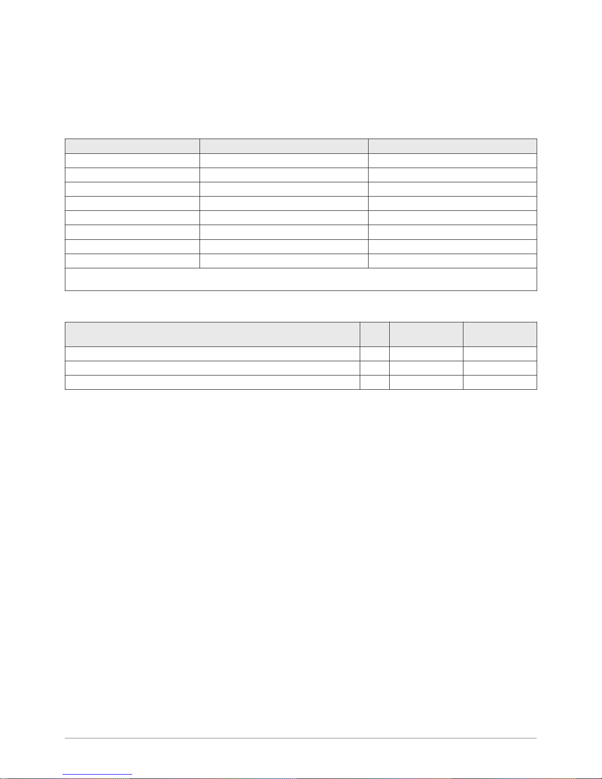
Tab.22 Weighting of boilers
Psup / (Prated + Psup)
(1)(2)
II, package without hot water storage tank II, package with hot water storage tank
0 0 0
0.1 0.3 0.37
0.2 0.55 0.70
0.3 0.75 0.85
0.4 0.85 0.94
0.5 0.95 0.98
0.6 0.98 1.00
≥ 0.7 1.00 1.00
(1) The intermediate values are calculated by linear interpolation between the two adjacent values.
(2) Prated is related to the preferential space heater or combination heater.
Tab.23 Package efficiency
Baxi - POWER HT + POWER HT+
1.50
POWER HT+
1.70
Seasonal space heating energy efficiency of boiler % 93 93
Temperature control % 2 2
Seasonal space heating energy efficiency of package % 95 95
12 Appendix
40 POWER HT + 7609475 - v04 - 15072015
Page 41

12 Appendix
7609475 - v04 - 15072015 POWER HT + 41
Page 42

12 Appendix
42 POWER HT + 7609475 - v04 - 15072015
Page 43

© Copyright
All technical and technological information contained in these technical instructions, as well as any drawings and technical de
scriptions supplied, remain our property and shall not be multiplied without our prior consent in writing. Subject to alterations.
Page 44

36061 BASSANO DEL GRAPPA (V I) - ITALY
Via Trozzetti, 20
Servizio clienti: Tel +39 0424 517800 - Fax +39 0424 38089
www.baxi.it
7609475 - v04 - 15072015
7609475-001-04
 Loading...